creep properties of steel p92 - tangerkonsys-t.tanger.cz/files/proceedings/metal_10/lists/...1....
TRANSCRIPT

18. ‐ 20. 5. 2010, Roznov pod Radhostem, Czech Republic, EU
CREEP PROPERTIES OF STEEL P92
Tomáš VLASÁK1, Jan HAKL1, Josef KASL2 a Josef ČMAKAL3
1SVÚM a.s., Podnikatelská 595, 190 11 Praha 9 <[email protected]> 2Škoda výzkum, Tylova 57, 316 00 Plzeň <[email protected]>
3UJP a.s., Nad Kamínkou 1343, 156 10 Praha 5 <[email protected]>
Abstract
Within the previous few years it is possible to observe an application of steel P91 and P92 in energy. Steel P92 was developed in Japan. It is alloyed by 9%Cr-1,8%W and further by little additions of Mo, V, Nb, B and N. Our contribution deals with the creep properties of this material in dependence on way of taking samples.
1. INTRODUCTION
Martensitic steels P91 and P92 are beginning to play a steadily more important role in power engineering in the last years. The steel P91 originates from the USA and contains 9Cr-1Mo (V,Nb,N). It was developed at the end of the seventies in the past century. The steel P92 with a higher resistance to heat was developed later in Japan and its alloying consists of 9Cr-1,8W (Mo,V,B,Nb,N). Our contribution deals with a thick wall tube from the steel P92 and concerns creep properties in dependence on the manner of taking samples.
2. EXPERIMENTAL MATERIAL
A seamless tube from the P92 steal with the tube outside diameter of 350 mm and the wall thickness of 39 mm was used for studying creep properties. The length of the tube that was available was 139 mm. The tube was made in Productos Tubulares, s.a.u., in Spain under the melt designation 60074. The chemical composition of the material according to [1] and the Spain certificate is indicated in Table I. The material was processed thermally using the 1050°C/60min+780°C/140min procedure. Its properties given in the acceptance report are in Table II. It is obvious from Table I and II that the material complies.
Tab.I. Chemical composition (% wt).
C Mn Si P S Cr Ni Mo V B Nb Al N W min max
0.07 0.13
0.3 0.6
0.5
0.02
0.01
8.5 9.5
0.4
0.3 0.6
0.15 0.25
0.001 0.006
0.04 0.09
0.04
0.03 0.07
1.5 2.0
Heat 60074 0.11 0.48 0.37 0.013 0.005 8.58 0.09 0.33 0.227 0.0015 0.058 0.017 0.0368 1.62
For understanding the creep properties, the tube was divided so that it was possible to observe the creep resistance on the surface, in the middle and on the inner tube part. The intake of samples whose specific sizes were Ø5x25 mm is illustrated in Fig.1.
A sample was also taken from the tube on which it was possible to measure the HV10 hardness in the direction from the outer surface toward the inner surface.
Tab.II. Mechanical properties Mechanical properties
RP0,2 (MPa) Rm (MPa) A (%) HB min max
440 620 20 250
Heat 60074 555 737 23.7 218

18. ‐ 20. 5. 2010, Roznov pod Radhostem, Czech Republic, EU
r175 r141
r170
r155,5
39
3. THE EFFECT OF THICKNESS ON THE MATERIAL PROPERTIES
The creep properties were determined at temperatures 575 to 650°C and in the range of stress from 120 to 220 MPa. The duration of the longest finished tests was approximately 6,500 hours. Tests are continuing further. The results of the creep tests are illustrated graphically in Fig.2. It is obvious that the area near the tube surface has the highest resistance against creep, the area at the inner surface has the lowest resistance. The properties in the centre of the tube bearing cross section are definitely minimal. This is reviewed in Fig.3.
Fig.2 Creep strength in different places of wall Fig.3 Creep strength in different places of wall
The course of hardness is analogous. Although the HV10 results are affected by the errors of measurements, we can conclude by fitting them mathematically that the first maximum of the curve is near the outer surface. This is obvious from Fig 4. The minimum is approximately in the middle of the bearing part. The second maximum, a little bit lower than the first one, is at the inner rim of the tube.
The course of HV10 thus corresponds to the results of heat resistance. The minimum of creep resistance is at the hardness minimum.
Fig.4 Hardness profile of tube wall
y = 1E-05x5 - 0,0014x4 + 0,0575x3 - 0,9702x2 + 5,7481x + 226,53
215
220
225
230
235
240
245
250
0 5 10 15 20 25 30 35 40Distance from outer surface [mm]
Har
dnes
s H
V10
[-]
Fig.1 Scheme of tube sampling
2
2,1
2,2
2,3
2,4
36500 37000 37500 38000 38500 39000 39500
PLM=T.(logtr+40), T[K], tr[h]
log
stre
ss ([
MPa
])
inner
outer
central
10
100
1000
10000
90 110 130 150 170 190 210 230
Stress [MPa]
Tim
e to
rupt
ure
[h]
Outer
Central
Inner
650°C 575°C600°C625°C

18. ‐ 20. 5. 2010, Roznov pod Radhostem, Czech Republic, EU 4. METALLOGRAPHY
In relation to these creep results and hardness measurements, metallographic investigation was carried in the areas with maximum and minimum properties. Samples represented the material in the initial state, i.e. before creep. Analyses were carried out with a magnification of 100 to 1 000, after etching the surface with agent Kalling No.2. However, optical metallography did not bring any result. Structures representing surfaces at the outer and inner rim and the central part are illustrated in Fig. 5 with a magnification of 400. Structures are formed by tempered martensite and do not exhibit observable differences.
a b
Magnitude 400x
Fig.5 Structure of outer (a), central (b) and inner part of wall thickness
c
For this reason a scanning electron microscope was used making it possible to observe structures with a higher magnification. Samples were observed in a state etched by agent Villela-Bain with a magnification of 1 000 to 20 000. The structure of the tube is displayed in Fig. 6 in the same manner as in Fig. 5 at a magnification of 3 000 to 10 000. The occurrence of an increased number of coarse particles was found in the sample from the central area in comparison with the samples from the tube rim. The M23C6 carbides are coarser, but according to the morphology of the coarsest particles, one can also consider the presence of a Laves phase. This was not possible to prove by ED microanalysis due to the subtle character of the particles, but the study continues by observing the carbon extraction replicas.

18. ‐ 20. 5. 2010, Roznov pod Radhostem, Czech Republic, EU
REM Ph.No. 4173 magnitude 3 000x REM Ph.No. 4174 magnitude 10 000x
a) outer part of wall thickness
REM Ph.No. 4186 magnitude 3 000x REM Ph.No. 4189 magnitude 10 000x SEI
b) central part of wall thickness
REM Ph.No. 4176 magnitude 3 000x REM Ph.No. 4179 magnitude 10 000x SEI
c) inner part of wall thickness
Fig.6 Microstructures of outer (a), central (b) and inner part of wall thickness in magnitudes 3000x and 10000x
18. ‐ 20. 5. 2010, Roznov pod Radhostem, Czech Republic, EU 5. DISCUSSION
In our opinion, the differences in the properties of steel are caused by imperfect thermal processing. The reason may be that the material was heated during homogenization for a shorter time than was necessary for heating the inner part of the tube. However, this finding is surprising, because no such effect has been found so far in any (8-12)%Cr steel. The common fact is that the thicknesses of the walls of products may also be significantly larger. We have not even found in the available literature that the dependence of the properties on the wall thickness differences would be mentioned.
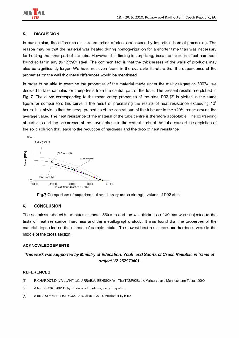
In order to be able to examine the properties of the material made under the melt designation 60074, we decided to take samples for creep tests from the central part of the tube. The present results are plotted in Fig. 7. The curve corresponding to the mean creep properties of the steel P92 [3] is plotted in the same figure for comparison; this curve is the result of processing the results of heat resistance exceeding 105 hours. It is obvious that the creep properties of the central part of the tube are in the ±20% range around the average value. The heat resistance of the material of the tube centre is therefore acceptable. The coarsening of carbides and the occurrence of the Laves phase in the central parts of the tube caused the depletion of the solid solution that leads to the reduction of hardness and the drop of heat resistance.
Fig.7 Comparison of experimental and literary creep strength values of P92 steel
6. CONCLUSION
The seamless tube with the outer diameter 350 mm and the wall thickness of 39 mm was subjected to the tests of heat resistance, hardness and the metallographic study. It was found that the properties of the material depended on the manner of sample intake. The lowest heat resistance and hardness were in the middle of the cross section.
ACKNOWLEDGEMENTS
This work was supported by Ministry of Education, Youth and Sports of Czech Republic in frame of project VZ 257970001.
REFERENCES
[1] RICHARDOT,D.-VAILLANT,J.C.-ARBAB,A.-BENDICK,W.: The T92/P92Book. Vallourec and Mannesmann Tubes, 2000.
[2] Attest No 3320700112 by Productos Tubulares, s.a.u., Espaňa.
[3] Steel ASTM Grade 92. ECCC Data Sheets 2005. Published by ETD.
100
1000
33000 35000 37000 39000 41000PLM=T.(log(tr)+40), T[K], tr[h]
Stre
ss [M
Pa]
P92 mean [3]
P92 + 20% [3]
P92 - 20% [3]
Experiments