creep characteristics of austenitic stainless steel...
TRANSCRIPT
1
CREEP CHARACTERISTICS OF AUSTENITIC STAINLESS STEEL FOILS
UNDER OXIDATIVE AND NON-OXIDATIVE ENVIRONMENT
FATIMAH MOHAMMED KADHIM
UNIVERSITI TEKNOLOGI MALAYSIA

4
CREEP CHARACTERISTICS OF AUSTENITIC STAINLESS STEEL FOILS
UNDER OXIDATIVE AND NON-OXIDATIVE ENVIRONMENT
FATIMAH MOHAMMED KADHIM
A project report submitted in partial fulfilment of the
requirements for the award of the degree of
Master of Engineering (Mechanical)
Faculty of Mechanical Engineering
Universiti Teknologi Malaysia
JANUARY 2015

iii
Dedicated to
My dearest country IRAQ
My parents, Mohammed Kadhim (Late) and Hekma Attallah,
My respected supervisor Professor Dr Mohd Nasir Tamin
All my family and friends for their immeasurable support and love throughout my
journey for education.
iv
ACKNOWLEDGEMENT
In the name of ALLAH, the most gracious and the most merciful, Who has
taught man what he did not know. The completion of this research was not possible
without His help and mercy. HE is the one who knows the hardships and HE is the
one I seek HIS satisfaction and ask HIS acceptance.
I would like to express my deepest gratitude towards my supervisor,
Professor Dr. Mohd Nasir Tamin for his guidance, encouragement and valuable
comments during the research and writing of this thesis. His attention and technical
expertise was key elements to my success. I am satisfied in gaining an in depth
knowledge from him.
I wish to express my appreciation to my Computational and Solid Mechanics
(CSM) - lab members for their generous cooperation, hospitality, time and insight on
related matters during this research. Also thank you to Ali Farokhi Nejad for helping
and assisting in running the experiment. The experimental work would not have
been possible without the help from you.
Special thank goes to my parents, Mohammed Kadhim and Hekma Attallah
and family members for their patience and sacrifice during my academic career.
Their concern, encouragement, moral and financial support over the years has always
been a source of motivation that enables me to achieve this degree.
Last but not the least, Thank Allah until you are satisfied and after
satisfaction first and foremost.
v
ABSTRACT
Compact and high efficiency recuperator with thin foil corrugated air cell as
the primary surface is employed in clean and efficient microturbine system (100
kW). Current primary surface recuperators are made of AISI 347 austenitic stainless
steel foils that operate at gas inlet temperature of less than 650 °C and attain
approximately 30 percent of efficiency. Efficiency of greater than 40 percent is
possible with the increase in turbine inlet temperature to 1230 °C, and as a result
recuperator inlet temperature increase to 843 °C. This study establishes base line
creep rupture behaviour of AISI 347 austenitic stainless steel foils at operating
temperature of 700 °C and applied stresses of 150,182 and 221 MPa in air as
oxidation environment, and in inert gas (Argon gas) as non-oxidation environment.
Creep behaviour of the foil shows that the primary creep stage is short and creep life
of the foil is dominated by secondary and tertiary creep deformation. The time to
rupture for the foil specimen is 78 hours with the corresponding rupture strain of
18.42 percent in air and 102 hours with the corresponding rupture strain of 15
percent in Argon gas for the applied stresses of 150,182 and 221 MPa at 700 °C.
Creep curves for AISI 347 austenitic stainless steel foil at 700 °C and at 150,182 and
221 MPa are well represented by the modified Theta-Projection concept model with
hardening and softening terms. The creep coefficients, θ1 and θ3, and the exponent
α are 0.0355, 0.04645 and 1.39 respectively in air and 0.0035, 0.048 and 1.3
respectively in Ar gas environment. Theta-Projection parameter values of the creep
curves at temperature of 700 °C and applied stress of range 150,182 and 221 MPa
shows a sudden gradient change at applied stress of 150 MPa possibly due to
different mechanism of dislocation movements and microstructure changes. the creep
curves for AISI 347 austenitic stainless steel foil at 700 °C and at 150,182 and 221
MPa in inert gas are represented by the power-law model and parameters of this
model A, n and Q are 7.947(1010) , 1.73 and 556.4KJ/mol., respectively. Two
different creep failure mechanisms for austenitic stainless steel foils are possible
since the creep failure data falls very close to the boundary of dislocation and
diffusion creep regions in the creep mechanism map for bulk material.morphology of
fractured foil surface revealed intergranular fracture with shallow network of faceted
voids. The formation of creep cavities is significant. Post test phase analysis
indicates the formation of carbides, namely Cr23C6, NbC and Fe3Nb3 C.
vi
ABSTRAK
Pemulih padat serta berkecekapan tinggi dengan kerajang tipis sel udara
beralun sebagai permukaan utama digunakan dalam sistem mikroturbin bersih dan
cekap (100 kW). Pemulih permukaan utama semasa diperbuat daripada AISI 347
kerajang austenit keluli tahan karat yang beroperasi pada suhu gas masuk kurang
daripada 650 °C serta mencapai kira-kira 30 peratus kecekapan. Kecekapan yang
lebih besar daripada 40 peratus adalah mungkin dengan peningkatan suhu masuk
turbin hingga 1230 °C, dan hasilnya suhu masuk pemulih meningkat hingga 843 °C.
Kajian ini menetapkan garis asas kelakuan rayapan pecah AISI 347 austenit kerajang
keluli tahan karat pada suhu operasi pada 700 °C dan tekanan yang digunakan adalah
150.182 dan 221 MPa dalam udara persekitaran pengoksidaan dan dalam gas lengai
(gas Argon) sebagai persekitaran bukan-pengoksidaan. Kelakuan rayapan kerajang
menunjukkan bahawa peringkat rayapan utama adalah pendek dan jangka hayat
rayapan kerajang dikuasai oleh pengubahbentuk rayapan sekunder dan tertier. Masa
untuk pecah bagi spesimen kerajang adalah 78 jam dengan ketegangan kepecahan
yang sepadan sebanyak 18.42 peratus di udara dan 102 jam dengan ketegangan
kepecahan yang sepadan sebanyak 15 peratus dalam gas Argon. Lengkung rayapan
bagi kerajang austenit keluli tahan karat AISI 347 pada 700 °C, 150,182 dan 221
MPa diwakili dengan menggunakan model konsep Unjuran Theta yang diubah suai
daripada segi pengerasan dan pelembutan. Pekali rayapan, θ1 dan θ3, dan α
eksponen adalah 0,0355, 0,04645 dan 1.39 masing-masing di udara dan 0,0035,
0,048 dan 1.3 masing-masing dalam gas lengai. Nilai parameter-parameter Unjuran
Theta rayapan eksperimen pada suhu 700 °C dan tekanan digunakan daripada julat
150,182 dan 221 MPa menunjukkan perubahan secara tiba-tiba pada kecerunan
tekanan gunaan pada 150 MPa mungkin disebabkan oleh mekanisma yang berbeza
daripada pergerakan kehelan dan perubahan-perubahan mikrostruktur dan juga
lengkuk rayapan bagi kerajang austenit keluli tahan karat AISI 347 pada 700 °C,
150,182 dan 221 MPa dalam gas lengai diwakili oleh model kuasa-hukum dan
parameter-parameter model ini adalah A, n dan Q iaitu masing-masing〖7,947 * 10
〗 ^ 10, 1.73 dan 556.4KJ/mol. Dua mekanisme kegagalan rayapan yang berbeza
bagi austenit kerajang keluli tahan karat adalah mungkin kerana data kegagalan
rayapan berada sangat dekat dengan sempadan kehelan dan kawasan resapan rayapan
dalam peta mekanisme rayapan untuk bahan pukal.
vii
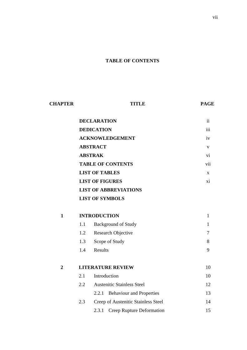
TABLE OF CONTENTS
CHAPTER TITLE PAGE
DECLARATION ii
DEDICATION iii
ACKNOWLEDGEMENT iv
ABSTRACT v
ABSTRAK vi
TABLE OF CONTENTS vii
LIST OF TABLES x
LIST OF FIGURES xi
LIST OF ABBREVIATIONS
LIST OF SYMBOLS
1 INTRODUCTION 1
1.1 Background of Study 1
1.2 Research Objective 7
1.3 Scope of Study 8
1.4 Results 9
2 LITERATURE REVIEW 10
2.1 Introduction 10
2.2 Austenitic Stainless Steel 12
2.2.1 Behaviour and Properties 13
2.3 Creep of Austenitic Stainless Steel 14
2.3.1 Creep Rupture Deformation 15
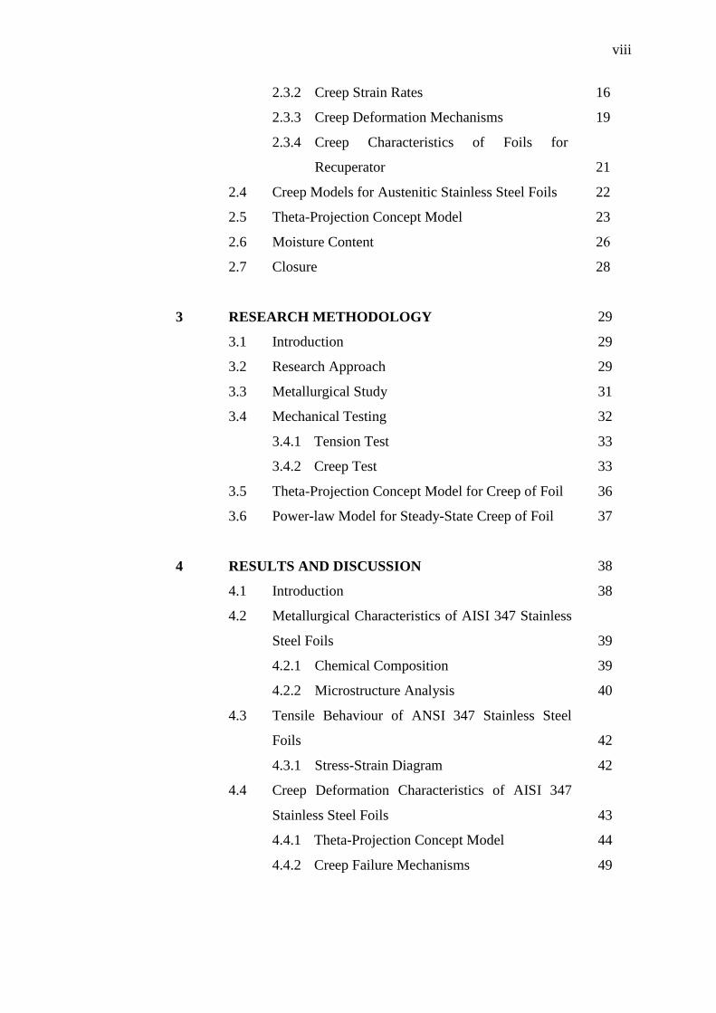
viii
2.3.2 Creep Strain Rates 16
2.3.3 Creep Deformation Mechanisms 19
2.3.4 Creep Characteristics of Foils for
Recuperator 21
2.4 Creep Models for Austenitic Stainless Steel Foils 22
2.5 Theta-Projection Concept Model 23
2.6 Moisture Content 26
2.7 Closure 28
3 RESEARCH METHODOLOGY 29
3.1 Introduction 29
3.2 Research Approach 29
3.3 Metallurgical Study 31
3.4 Mechanical Testing 32
3.4.1 Tension Test 33
3.4.2 Creep Test 33
3.5 Theta-Projection Concept Model for Creep of Foil 36
3.6 Power-law Model for Steady-State Creep of Foil 37
4 RESULTS AND DISCUSSION 38
4.1 Introduction 38
4.2 Metallurgical Characteristics of AISI 347 Stainless
Steel Foils 39
4.2.1 Chemical Composition 39
4.2.2 Microstructure Analysis 40
4.3 Tensile Behaviour of ANSI 347 Stainless Steel
Foils 42
4.3.1 Stress-Strain Diagram 42
4.4 Creep Deformation Characteristics of AISI 347
Stainless Steel Foils 43
4.4.1 Theta-Projection Concept Model 44
4.4.2 Creep Failure Mechanisms 49

ix
5 CONCLUSIONS AND RECOMMENDATIONS 55
5.1 Conclusions 55
5.2 Recommendations 56
REFERENCES 57
x
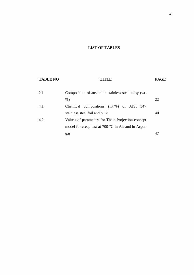
LIST OF TABLES
TABLE NO TITLE PAGE
2.1 Composition of austenitic stainless steel alloy (wt.
%) 22
4.1 Chemical compositions (wt.%) of AISI 347
stainless steel foil and bulk 40
4.2 Values of parameters for Theta-Projection concept
model for creep test at 700 °C in Air and in Argon
gas 47

xi
LIST OF FIGURES
FIGURE NO TITLE PAGE
1.1 Microturbine based CHP System [5] 2
1.2 Microturbine Generation (MTG) Components [8] 3
1.3 Schematic of corrugated air-cell in thin foils
primary surface Recuperator [7] 4
1.4 Efficiency as a Fucntion of profile [4] 5
1.5 Microturbine Efficiency as a Function of
Recuperator Effectiveness 6
2.1 Illustration of the effect of temperature and stress on
creep behavior of alloy 16
2.2 Typical shape of creep curve [27]. 17
2.3 (a) Steady state creep rate as a function of applied
stress at constant temperature (b) as a function of
temperature at constant stress [28] 19
2.4 Deformation mechanism map for AISI 304. [29] 20
2.5 Schematic diagrams of viscoelasticity
demonstration on creep [11] 27
3.1 Research framework 30
3.2 Geometry of creep test specimen. Dimensions in
mm 32
3.3 INSTRON Universal Testing Machine used for
tension test 33
3.4 Creep test set up in air for thin foil specimen 34
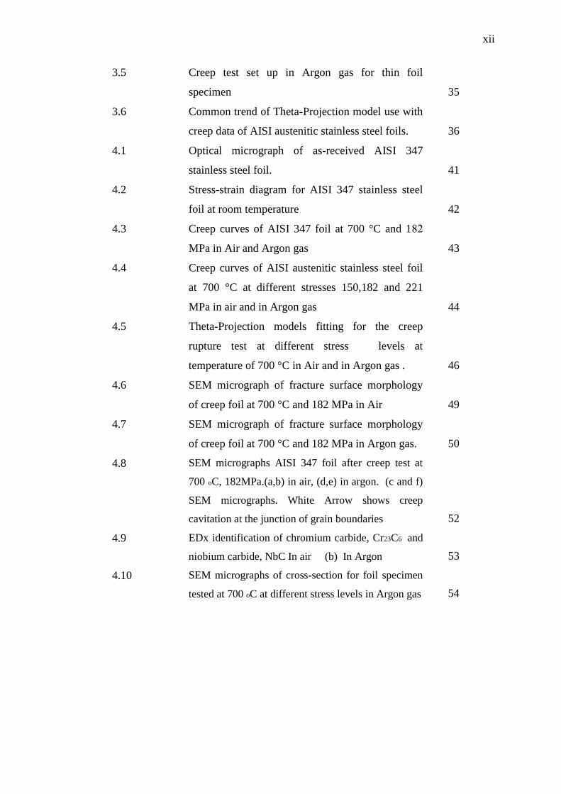
xii
3.5 Creep test set up in Argon gas for thin foil
specimen 35
3.6 Common trend of Theta-Projection model use with
creep data of AISI austenitic stainless steel foils. 36
4.1 Optical micrograph of as-received AISI 347
stainless steel foil. 41
4.2 Stress-strain diagram for AISI 347 stainless steel
foil at room temperature 42
4.3 Creep curves of AISI 347 foil at 700 °C and 128
MPa in Air and Argon gas 43
4.4 Creep curves of AISI austenitic stainless steel foil
at 700 °C at different stresses 150,182 and 221
MPa in air and in Argon gas 44
4.5 Theta-Projection models fitting for the creep
rupture test at different stress levels at
temperature of 700 °C in Air and in Argon gas . 46
4.6 SEM micrograph of fracture surface morphology
of creep foil at 700 °C and 182 MPa in Air 49
4.7 SEM micrograph of fracture surface morphology
of creep foil at 700 °C and 182 MPa in Argon gas. 50
4.8 SEM micrographs AISI 347 foil after creep test at
700 oC, 182MPa.(a,b) in air, (d,e) in argon. (c and f)
SEM micrographs. White Arrow shows creep
cavitation at the junction of grain boundaries 52
4.9 EDx identification of chromium carbide, Cr23C6 and
niobium carbide, NbC In air (b) In Argon 53
4.10 SEM micrographs of cross-section for foil specimen
tested at 700 oC at different stress levels in Argon gas 54
xiii
LIST OF ABBREVIATIONS
AISI - American Iron and Steel Institute
ASME - American Society of Mechanical Engineers
ASTM - American Society for Testing and Materials
CHP - Combined Heat and Power
DG - Distributed Generation
EDX - Energy Dispersive X-ray Spectroscopy
FESEM - Field Emission Scanning Electron Microscope
HHV - Higher Heating Value
LVDT - Linear Variable Differential Transformer
MTG - Microturbine Generation
PID - Proportional-Integral-Derivative
xiv
LIST OF SYMBOLS
𝜀0 - Instantaneous strain
𝜀𝑐𝑟 - Creep strain
𝜀𝑝𝑟𝑖𝑚𝑎𝑟𝑦 - Primary creep
𝜀𝑡 - Total strain
𝜀𝑡𝑒𝑟𝑡𝑖𝑎𝑟𝑦 - Tertiary creep
ε𝑠𝑠∙
- Strain rate
t - time
T - Operating temperature
𝑇𝑚 - Melting temperature
wt. % - Weight percentage
α - Rate constant
𝜃1 , 𝜃3 - Parameters describing the primary and tertiary stages
𝜃2 , 𝜃4 - Rate parameters characterize the curvature of the primary and
tertiary stages
n - Creep exponent
A - Creep coefficient
Q - The activation energy for creep
R - The gas constant, R = 8.314 J/mol.K
1
CHAPTER 1
INTRODUCTION
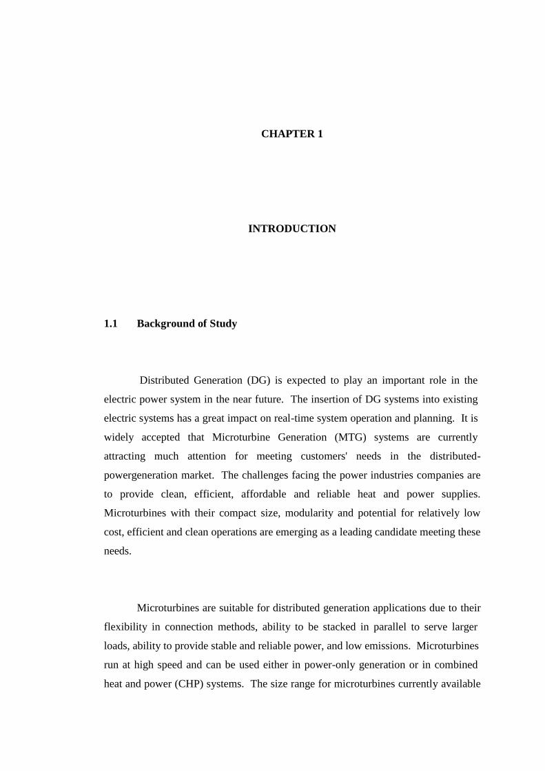
1.1 Background of Study
Distributed Generation (DG) is expected to play an important role in the
electric power system in the near future. The insertion of DG systems into existing
electric systems has a great impact on real-time system operation and planning. It is
widely accepted that Microturbine Generation (MTG) systems are currently
attracting much attention for meeting customers' needs in the distributed-
powergeneration market. The challenges facing the power industries companies are
to provide clean, efficient, affordable and reliable heat and power supplies.
Microturbines with their compact size, modularity and potential for relatively low
cost, efficient and clean operations are emerging as a leading candidate meeting these
needs.
Microturbines are suitable for distributed generation applications due to their
flexibility in connection methods, ability to be stacked in parallel to serve larger
loads, ability to provide stable and reliable power, and low emissions. Microturbines
run at high speed and can be used either in power-only generation or in combined
heat and power (CHP) systems. The size range for microturbines currently available
2
and in development is from 30 to 250 kilowatts (kW), while conventional gas turbine
sizes range from 500 kW to 250 megawatts (MW) [1].
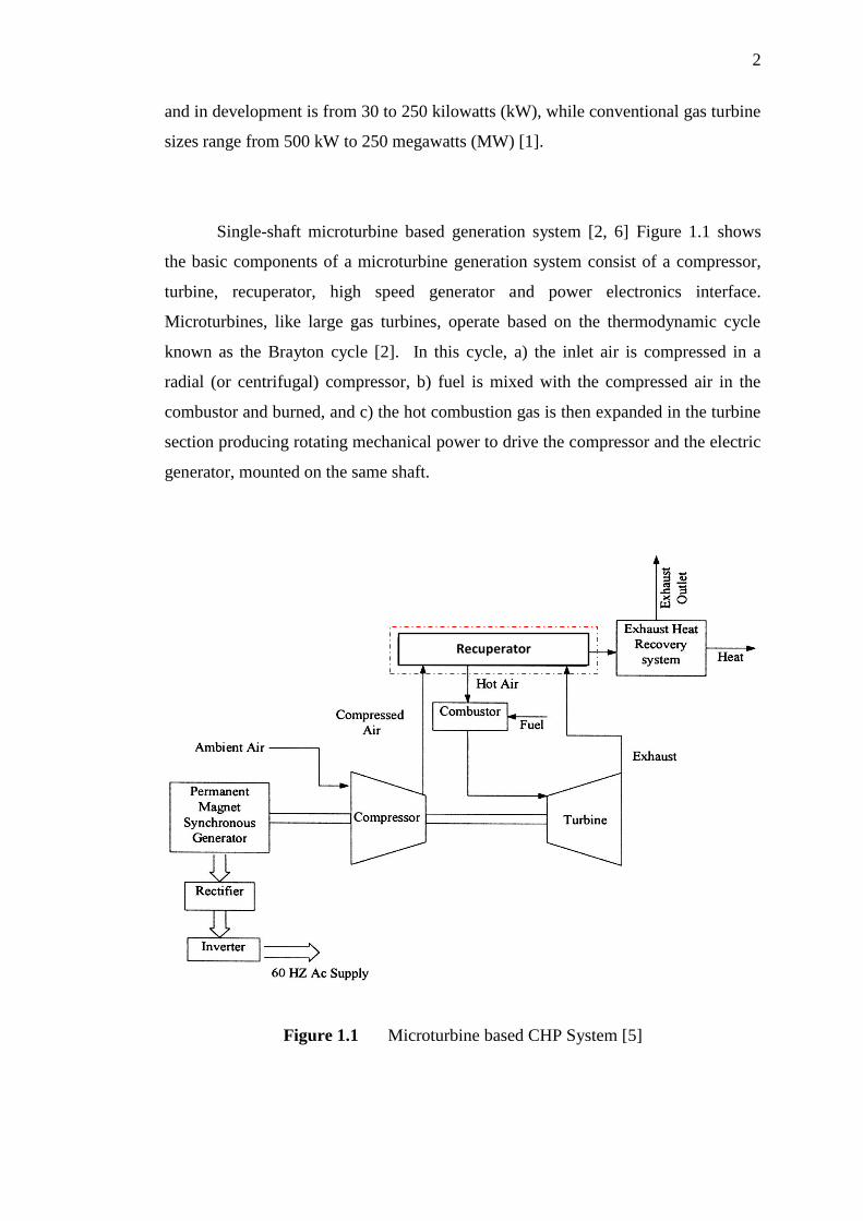
Single-shaft microturbine based generation system [2, 6] Figure 1.1 shows
the basic components of a microturbine generation system consist of a compressor,
turbine, recuperator, high speed generator and power electronics interface.
Microturbines, like large gas turbines, operate based on the thermodynamic cycle
known as the Brayton cycle [2]. In this cycle, a) the inlet air is compressed in a
radial (or centrifugal) compressor, b) fuel is mixed with the compressed air in the
combustor and burned, and c) the hot combustion gas is then expanded in the turbine
section producing rotating mechanical power to drive the compressor and the electric
generator, mounted on the same shaft.
Figure 1.1 Microturbine based CHP System [5]
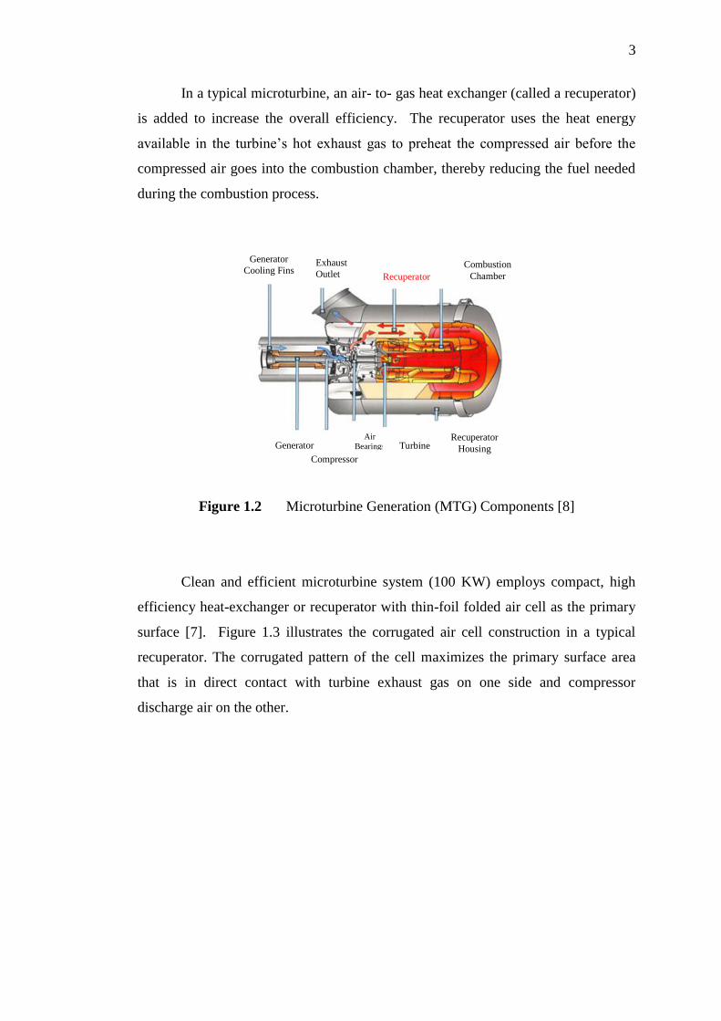
Recuperator
3
In a typical microturbine, an air- to- gas heat exchanger (called a recuperator)
is added to increase the overall efficiency. The recuperator uses the heat energy
available in the turbine’s hot exhaust gas to preheat the compressed air before the
compressed air goes into the combustion chamber, thereby reducing the fuel needed
during the combustion process.
Figure 1.2 Microturbine Generation (MTG) Components [8]
Clean and efficient microturbine system (100 KW) employs compact, high
efficiency heat-exchanger or recuperator with thin-foil folded air cell as the primary
surface [7]. Figure 1.3 illustrates the corrugated air cell construction in a typical
recuperator. The corrugated pattern of the cell maximizes the primary surface area
that is in direct contact with turbine exhaust gas on one side and compressor
discharge air on the other.
Generator
Cooling Fins Exhaust
Outlet Recuperator
Combustion
Chamber
Generator Compressor
Air
Bearings Turbine Recuperator
Housing
4
Figure 1.3 Schematic of corrugated air-cell in thin foils primary surface
recuperator [7]
Combined heat and power system efficiency of a microturbine is a function
of the exhaust heat temperature. Recuperator effectiveness strongly influenced by
the microturbine exhaust temperature. Effectiveness in heat exchanger industry is
for ratio of the actual heat transferred to the maximum achievable. Most
microturbines include built in recuperator. The inclusion of a high effectiveness (90
percent) recuperator essentially doubles the efficiency of a microturbine with a
pressure ratio of 3.2, from about 14 percent to about 29 percent depending on
component details [1]. With the addition of the recuperator, a microturbine can be
suitable for intermediate duty or price-sensitive base load service.
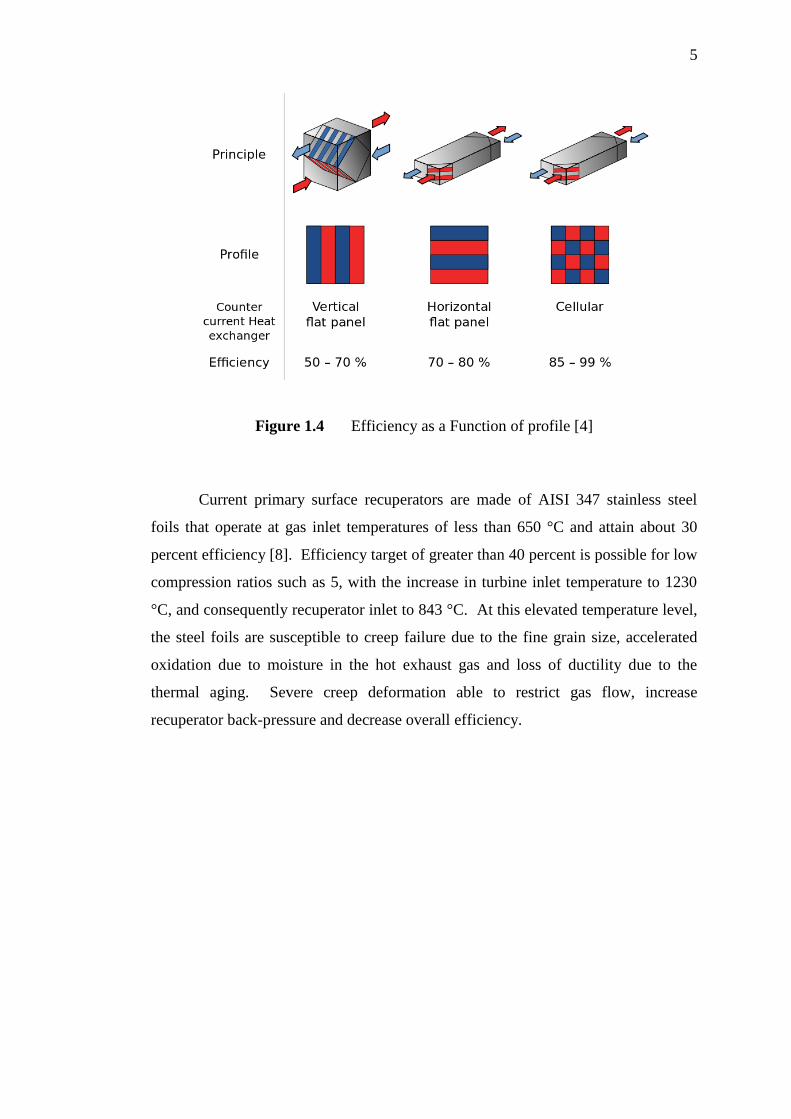
The efficiency of heat exchanger or recuperator depends on arranging and
profile since the efficiency increase with increase surface area that clear in figure 1.4.
Ai
r
Gas
Primary
Sheet A
Primary
Sheet B
Contact only-
not permanently
bonded
5
Figure 1.4 Efficiency as a Function of profile [4]
Current primary surface recuperators are made of AISI 347 stainless steel
foils that operate at gas inlet temperatures of less than 650 °C and attain about 30
percent efficiency [8]. Efficiency target of greater than 40 percent is possible for low
compression ratios such as 5, with the increase in turbine inlet temperature to 1230
°C, and consequently recuperator inlet to 843 °C. At this elevated temperature level,
the steel foils are susceptible to creep failure due to the fine grain size, accelerated
oxidation due to moisture in the hot exhaust gas and loss of ductility due to the
thermal aging. Severe creep deformation able to restrict gas flow, increase
recuperator back-pressure and decrease overall efficiency.

6
Recuperator Effectiveness (percent)
Figure 1.5 Microturbine Efficiency as a Function of Recuperator Effectiveness
Creep deformation is mutually accommodated by a combination of elastic
deformation, localized plastic deformation, non-uniform creep, grain boundary
sliding and diffusion flow through the grains, along grain and free surfaces [8]. The
second phase particles are also responsible for cavity production which leads to
intergranular failures [9]. The most important and major step in developing
recuperators with upgraded performance is to characterize the current technology.
combination of oxidation and corrosion behaviour, and tensile and creep strengths
determine the upper temperature and useful lifetime limits. In this respect, creep
tests on commercial AISI Type 347 steel recuperator stock has been conducted [6].
Aging effects on the steel up to 30,000 hours above 700 °C has been established in
terms of detrimental sigma phase formation [7].
Properties and behavior of AISI 347 steel is generally known for processing
and fabrication into high-temperature components such as heat-exchanger piping and
gas turbine parts. However, information on these alloys fabricated into thin foils (0.1
– 0.25 mm-thick) for use in primary surface recuperators is limited or nonexistent.
7
Austenitic stainless steels are among the most widely used alloys for components
operating in high temperature environment, in heat exchanger or recuperator and
nuclear reactors. It is characterized by a minimum of 10.5 wt % Cr in order to form a
passive Cr2O3 layer which protects the metal from further corrosion. Austenitic
stainless steels also have additions of Ni to stabilize the austenite phase with a face
centered cubic (FCC) crystal structure.
The combination of high temperature air and significant water vapor is
common in energy generation devices such as, for example, gas turbines, steam
turbines, and fuel cells, and in heat exchangers and recuperators handling the gas
streams used or generated by such energy generation devices, as well as in
equipment for treating, processing, or extracting chemicals or minerals at high
temperatures. Accordingly, parts of such devices subjected to these conditions have
been fabricated from a variety of austenitic stainless steels.
1.2 Research Objectives
The main objective of this study is to establish baseline creep characteristic
and deformation mechanisms of AISI 347 austenitic stainless steel foils in air and in
inert gas (Argon gas) at elevated stress (150,182 and 221 MPa) and 700ᵒC through
the following tasks:
a) To establish tensile stress-strain diagram of the foil at room temperature.
b) To establish creep curve of foil at 700ᵒC and (150,182 and 221 MPa).
c) To determine creep model for the foil based on Theta projection concept and
power-law model.
d) To identify creep mechanism of the foil.
8
1.3 Scope of Study
The study covers for AISI 347 austenitic stainless steel foils with thickness of
0.25 mm. Microstructure and chemical composition analysis are performed on the
as-received foil. Tension tests of the foil are conducted at room temperature. Creep
tests are performed in laboratory air environment at isothermal temperature of 700
°C and non-oxidation environment (inert gas) at isothermal temperature of 700 °C.
The applied stress are (150,182 and 221) MPa. Fractographic study is carried out on
the fractured foil specimen. Theta projection concept model and power law creep
model are executed for describing the long-term creep deformation behaviour of the
foils.
1.4 Results
(Creep curves and models) set the baseline creep response of austenitic
stainless steel foils at elevated temperatures and stresses can be used to advance the
alloy for higher temperature applied with new composition metallurgy.
High efficiency heat exchangers are being developed for new distributed
power technology systems particularly microturbines system. Recuperator is the part
of microturbines that is responsible for a significant fraction of overall efficiency.
Recuperators often require thin-section of austenitic stainless steels operating at
elevated temperature ranges up to 800 °C. Most of the recuperators used austenitic
stainless steel of Type 347 because of its oxidation resistance properties and
competitive cost. At high temperatures which above 650 °C with the presence of
moisture environment of the turbine exhaust gas, the material is susceptible to creep
and oxidation. These will cause fouling and structural deterioration and leaks,
rapidly reducing the effectiveness and life of the recuperator. Therefore the study is

9
to establish creep characteristics and deformation mechanisms of AISI Type 347
austenitic stainless steel foils at 700 °C and (150,182 and 221) MPa in air and inert
gas.
57
REFERENCES
1. Shah, R.K. Compact Heat Exchangers for Microturbines. in Micro
GasTurbines. 2005. Neuilly-sur-Seine, France: RTO.
2. Goldstein L., Hedman B., Knowles D., Freedman S. I., Woods R., and
Schweizer T. 2003. Gasfired Distributed Energy Resource Technology
Characterizations. National Renewable Energy Laboratory, NREL/TP-620-
34783.
3. Lasseter R. 2001. Dynamic Models for Micro-Turbines and Fuel Cells. Proc.
IEEE PES Summer Meeting, Vancouver, BC, Canada, vol. 2, pp. 761–766.
4. Puttgen H. B., Macgregor P. R., and Lambert F. C. 2003. Distributed
Generation: Semantic Hype or the Dawn of A New Era. IEEE Power and
Energy Magazine, vol. 1, no. 1, pp. 22–29.
5. Malmquist A. 1999. Analysis of a Gas Turbine Driven Hybrid Drive System for
Heavy Vehicles, Ph.D. Dissertation, School of Electrical Engineering and
Information Technology, KTH, Stockholm, Sweden.
6. Malmquist A., Aglen O., Keller E., Suter M., and Wickstrom J. 2000.
Microturbines: Speeding the Shift to Distributed Heat and Power. ABB Review,
no. 3, pp. 22–30.
7. Aquaro, D. and M. Pieve, 2007. Compact Heat Exchangers Optimization
Developing a Model for the Thermal-Fluid Dynamic Sizing. Heat Technology
25: p. 9-18.
8. Edgar Lara-Curzio R. T. K. M. P. M. a. B. 2004. Screening and Evaluation of
Materials for Microturbine Recuperators. in Proceedings of ASME Turbo Expo
2004 Power for Land, Sea and Air, Vienna, Austria,.
58
9. McDonald C.F. 1996. Heat Recovery Exchanger Technology for Very Small
Gas Turbines. International Journal of Turbo and jet Engines, vol. 13, pp. 239-
261.
10. Karen, Pavel; McArdle, Patrick; Takats, Josef. 2014. Toward a Comprehensive
Definition of Oxidation State (IUPAC Technical Report). Pure and Applied
Chemistry. 86
11. Mahmoud Sayed-Ahmed, Khaled Sennah, Effect of Temperature and Relative
Humidity on Creep Deflection for Permanent Wood Foundation Panels,
Department of Civil Engineering, Ryerson University, Toronto, Ontario,
Canada.
12. Michael P. Brady, Bruce A. Pint, Knoxville, Philip J. Maziasz, Yukinori
Yamamoto,Zhao P. Lu, Oxidation Resistant High Creep Strength Austenitic
Stainless Steel Oak Ridge, TN (US).
13. Osman H., Creep Rupture Behavior of AISI 347 Austenitic Stainless Steel Foils
at Different Temperature and Stress Levels, Universiti Teknologi Malaysia,
Johor, Malaysia, 2011.
14. McDonald, C.F., 2003. Recuperator Considerations for Future Higher
Efficiency Microturbines. Applied Thermal Engineering, 23(12): p. 1463-1487.
15. Massardo, A.F., C.F. McDonald, and T. Korakianitis. 2002. Microturbine/Fuel-
Cel Coupling for High-Efficiency Electrical-Power Generation. Journal of
Engineering for Gas Turbines and Power, 124(1): p. 110-116.
16. Ward, M.E., Primary Surface Recuperator Durability and Applications, in
Turbomachinery Technology Seminar 1995: San Diego, CA. p. 395.
17. Young, R. and P. Lovell, Introduction to Polymers. Cheltenham. 1991,
Cheltenham, UK: Stanley Thornes (Publishers) Ltd.
18. C.F.McDonald, 1996. Heat Recovery Exchanger Technology for Very Small
Gas Turbines. International Journal of Turbo and jet Engines, vol. 13, pp. 239-
261.
19. Curzio L. 2004. Screening and Evaluation of Materials for Microturbine
Recuperators. in Power for Land, Sea and Air, Proceedings of ASME Turbo
Expo Vienna, Austria, 2004.
20. Was G. S. 2007. Fundamental of Materials Science for Metals and Alloy,
Nuclear Engineering and Radiological Sciences, University of Michigan:
Springer Berlin Heidelberg New York, 2007.
59
21. Metals, A.S. and T.S. Department. 2008. The Atlas Specialty Metals Technical
Handbook of Stainless Steels Australia: Atlas Specialty Metals Technical
Services Department.
22. Li, J. and Dasgupta A., 1993. Failure-mechanism Models for Creep and Creep
Rupture. Reliability, IEEE Transactions on, 42(3): p. 339-353.
23. Dasgupta, A. and Hu J.M. 1992. Failure Mechanism Models for Plastic
Deformation. Reliability, IEEE Transactions on, 41(2): p. 168-174.
24. M.J.Collins, "Creep Strength in Steel and High Temperature Alloys," in
Proceeding of Meeting in University of Sheffield, London, UK, 1972.
25. Intrater, J. and Machlin E.S., Journal Institute of Metals 1959. 88: p. 305.
26. Honeycombe, R.W.K., Plastic Deformation of Metals. 1984: Hodder Arnold.
27. Dieter G.E., Mechanical Metallurgy, McGraw Hill, 1988.
28. Dieter G.E., Mechanical Metallurgy. SI Metric Edition ed. 1988: McGraw Hill.
29. Ashby, M.F., Gandihi C., and Taplin D.M.R. 1979. Fracture Mechanism Maps
and their Construction for F.C.C Metals and Alloys. Acta Metallurgica. 27: p.
699 - 729.
30. Maziasz, P.J. and Swindeman R. 2000. Advanced Microturbine Systems –
Program Plan for Fiscal Years 2000 – 2006. 2000, Office of Power
Technologies, Office of Energy Efficiency and Renewable Energy, U.S.
Department of Energy: Washington, D.C.
31. Holdsworth, S.R., et al., Factors Influencing Creep Model Equation Selection.
International Journal of Pressure Vessels and Piping. 85(1-2): p. 80-88.
32. Norton, F.H. 1929. The Creep of Steels at High Temperatures. New York:
McGraw-Hill.
33. Wilshire R. B. 1985 Creep of Metals and Alloys. IMM North American
Publication Center, vol. 5, p. 320.
34. H.Oikawa K. 1987. An Extrapolation Procedure of Creep Data. Journal of
Pressure Vessel Technology, vol. 109, no. 1, pp. 142-146.
35. Lan C. a. I.L. 2004. Fatigue Behavior of AISI 347 Stainless Steel in Various
Environments. Journal of Materials Science, vol. 39, no. 23, pp. 6901-6908.
36. Stinner, C. 2003. Processing to Improve Creep and Stress Rupture Properties
of Alloy T347 Foil. Allegheny Ludlum Technical Center Internal Report:
Brackenridge.
60
37. Laha, K., et al. 2005. Improved Creep Strength and Creep Ductility of Type
347 Austenitic Stainless Steel through the Self-Healing Effect of Boron for
Creep Cavitation. Metallurgical and Materials Transactions A. 36(2): p. 399-
409.
38. Minami, Y., Kimura H., and Tanimura M. 1985. Creep Rupture Properties of
18 Pct Cr-8 Pct Ni-Ti-Nb and Type 347H Austenitic Stainless Steels. Journal
of Materials for Energy Systems. 7(1): p. 45-54.
39. Sasmal, B. 1997. Mechanism of the Formation of M23C6 Plates Around
Undissolved NbC Particles in a Saustenitic Stainless Steel. Journal of
Materials Science. 32(20): p. 5439-5444.
40. Lewis, M.H. and Hattersley B. 1965. Precipitation of M23C6 in Austenitic
Steels. Acta Metallurgica. 13(11): p. 1159-1168.