creep behaviour of geosynthetics for sustainable construction · · 2014-02-06creep behaviour of...
TRANSCRIPT
RJCES Volume 1 [5] December 2013 www.aelsindia.com 34 | P a g e
Creep Behaviour of Geosynthetics for Sustainable Construction
Rajesh Kumar Jain Bharat Group of Colleges, Punjab, India
ABSTRACT
The load strain with-time behaviour (creep) of the reinforcement geosynthetic is a significant design consideration, particularly because these materials are called upon to perform for such long periods. Stepped Isothermal Method (SIM) has been used to standardized and evaluate the creep behavior of different types of geosynthetics as an alternative testing method. In addition, time-temperature-stress superposition (TTSS) is used to predict the creep behavior of polymeric materials by adding a stress factor to TTS. Three replicate tests were performed to evaluate the repeatability of the SIM test at the inclined condition of 1-to-4 under 20% σc. In both tensile and compressive SIM tests, a good agreement with the results from the conventional test method was observed. The reduction factors and the creep strains of the PET geosyntherics are much lower than those of HDPE (High Density Polyethylene) and PP (Poly Propylene) geosyntherics at the same percentage of ultimate working tensile strength. As a result, the HDPE and PP geosyn -therics is more sensitive to creep than the PET (Poly Ethylene Terephthalate) geosyntherics. The compressive strength decreased as the test temperature increases . The average ultimate tensile strengths (UTS) are 1.68 kN/strap (± 0.062) and 1.70 kN/rib (± 0.045) for the PET and HDPE geogrids, respectively. The creep strains of PET and HDPE geogrids reveal that the PET geogrid strained much less than the HDPE geogrid at the same percentage of UTS. At high applied loads (50% to 70% UTS for PET and 40% to 60% UTS for HDPE), the PET geogrid was dominated by the linear primary creep stage prior to the rupture. The confinement of the RAP sample significantly increased the strength of the sample and the stiffness values of single geocell-confined and embedded RAP and multi geocell-confined and embedded RAP bases were increased by 1.2 and 1.6 times compared to those of the unreinforced confined RAP bases respectively. Keywords: Geosynthetic, RAP, Polyethylene Polymer, Compaction, Creep. Received 17/08/2013 Accepted 22/10/2013 © 2013 AELS, India INTRODUCTION We shape our buildings and our buildings shape us. Buildings are our personal environments, products in which we are constantly immersed. The use of geosynthetics in civil engineering applications is often found to provide financial benefits through the reduced cost of imported materials, reduced cost of wastage, and generally more efficient use of resources compared with traditional solutions using soil, concrete, or steel. In addition, environmental benefits are also often found where, for example, the use of geosynthetic barriers can significantly improve the performance of natural materials as barrier layers. Geosynthetics are now a regular part of every infrastructure project specifications. Geosynthetics as reinforcement may require enduring exposure to both high tensile stresses for long periods of time typically 75-plus years as well short life. The load strain with-time behaviour (creep) of the reinforcement geosynthetic is a significant design consideration, particularly because these materials are called upon to perform for such long periods. Newly introduced polymeric systems include High Density Polyethylene (HDPE) or Polypropylene (PP) modular chambers with 95 to 98% void space.Worldwide demand for geosynthetics is projected to rise 5.3 percent annually to 4.7 billion square meters in 2013.India, China, Russia and other countries with large-scale infrastructure developments planned, and evolving environmental protection regulations and building construction codes are expected to register the strongest advances. Geo-synthetics are especially useful in an environment of increasing land scarcity, increased awareness of seismic hazards, and need more stringent environmental regulations especially in the context of India. Tremendous potential exists in Indian market .The use of 100% recycled aggregate with geosynthetic is a sustainable solution. As awareness of the potential environmental impacts of building construction has grown, efforts are being made to avoid these adverse effects and to work towards impact mitigation[1].There is a growing consensus that appropriate strategies and actions are needed to make buildings and construction activities more sustainable [2,3,4,5,6].Understanding the
Research Journal of Chemical and Environmental Sciences Res. J. Chem. Env. Sci., Volume 1 Issue 5 December 2013: 34-46 Online ISSN 2321-1040 CODEN: RJCEA2 [CAS, USA] Available Online http://www.aelsindia.com ©2013 AELS, India
ORIGINAL ARTICLE
RJCES Volume 1 [5] December 2013 www.aelsindia.com 35 | P a g e
environmental issues surrounding the extraction of raw materials, the manufacture of construction materials, and their effects in use, is important to ensure sustainability [7,1]. In the design of geosynthetics, one of the major issues, in absence of knowledge is to apply the appropriate creep reduction factors. Contrary, higher activation energies were resulted from the short-term accelerated tests in comparison to the long-term tests for geosyntherics. This creep reduction factor is either calculated by performing creep test or reduction factor calculated based on previous research worked. The reduction factors and the creep strains of the PET geosyntherics are much lower than those of HDPE (high density polyethylene) and PP (polypropylene) geosyntherics at the same percentage of ultimate working tensile strength. As a result, the HDPE and PP geosyntherics is more sensitive to creep than the PET (polyethylene terephthalate) geosyntherics. It has been shown that geosynthetic reinforcement materials made of polymers, typically polyester (PET), polypropylene (PP), and polyethylene (PE), are all susceptible to creep to some extent [8,9,10,11]. The mechanical behaviour of geosynthetics depends on a number of factors, such as the type of polymer, polymer structure, manufacturing process, loading conditions, and soil environment [8,12,13,14,15,16]. Generally, the creep rate of PE is greater than that of PP, which is greater than that of PET [13]. The stress-strain behaviour of a geosynthetic is also the function of strain rates [17,18,19,20,21] and ambient temperature [22,10,15,23,24]. The main advantage of SIM method is to avoid material variability by using a single test specimen [23]. The applicability of SIM to assess tensile creep behavior of geotextiles and geogrids has been investigated by many researchers [23,,25,26,27,28]. Recently, the compressive creep behavior of a geonet was also evaluated using SIM [29,30,31]. TTSS (Time-Temperature-Stress Superposition) utilizes not only temperatures but also stress to accelerate the creep, since both factors affect the creep deformation based on time-temperature and time-stress equivalences [32]. The method can be very useful for materials that cannot be exposed to higher elevated temperatures due to unexpectedly large amount or rate of creep induced by natural of the material i.e., low melting points [33]. Aims and Objectives The aim of this research is, therefore, to develop and verify the technical viability of using geosynthetics in construction. The need to evaluate the creep compatibility and life time of geosynthetic materials made of polyester, other than polypropylene has been evident in recent years. The objective of this paper is to review current progress and establish need to revise criteria for permissible creep in design of reinforced earth fill and reliable test house of repute. MATERIAL AND METHOD Stepped Isothermal Method (SIM) has been used to standardized and evaluate the creep behavior of different types of geosynthetics as an alternative testing method. In SIM, a sequence of creep responses on a single test specimen under a constant load is generated using a series of elevated temperature steps. The resulting creep responses at elevated temperatures are shifted along the log-time scale to a lower reference temperature to generate a creep master curve. In addition, time-temperature-stress superposition (TTSS) is used to predict the creep behavior of polymeric materials by adding a stress factor to TTS . Methods of life prediction Direct measurements on exhumed material, extrapolated in time (so far information has only been available for short durations) , results of simple (index) tests, which can be performed within a reasonable time. However, as with steel reinforcements, strength characteristics must be adjusted to account for potential degradation in the specific environmental conditions, even in relatively neutral soils. The formula for the straight line and its gradient b can be evaluated using standard regression analysis as:
y = ymean + b (x – xmean) where ymean and xmean are the means of all values of y and x respectively, and
b = Sxy/Sxx Sxx = Σ (x – xmean)²
Sxy = Σ (x – xmean) (y – ymean). The upper confidence limit of the Arrhenius line, corresponding to the maximum rate of degradation, is calculated from the formula:
y = ymean + b (x - xmean) + tn-2 σ0√[1 + 1/n + (x - xmean)²/Sxx] tn-2 is the value of Student’s t corresponding to n – 2 degrees of freedom and the required level of probability. Suppose that the confidence level required is a 95% probability that the predicted lifetime will be less than the confidence limit shown. As a check that the right criterion has been chosen, note that as n tends to infinity Student’s t tends to 1.64.
- σ0 = √[(Syy - Sxy2/ Sxx)/(n – 2)] n = number of measurements
Rajesh Kumar Jain
RJCES Volume 1 [5] December 2013 www.aelsindia.com 36 | P a g e
The value of Y extrapolated to the service conditions for the geosynthetic is denoted as the lifetime parameter Design aspects and characteristic material aspects The design aspects in relation to the functions of the geosynthetic. The design aspects are divided into material characteristics or properties. The relevant EN[34]standards and some relevant ASTM[35]standards are mentioned. There are also other standards which are used to determine the characteristic design aspects CUR[36]Building & Infrastructure . The RAP base was compacted at 5.5% moisture content to achieve 95% of the maximum dry density. Subgrade was prepared artificially by river sand . The sand used in this study was a poorly-graded sub-rounded river sand having a mean particle size (d50) = 0.54 mm.Cyclic plate loading tests were conducted in a large geotechnical test box system designed and fabricated for the geotechnical laboratory.These tests were conducted on unreinforced RAP bases (15 and 30 cm thick) and reinforced bases (15, 23, and 30 cm thick) using a servo hydraulic MTS loading system. Properties of Geosynthetics Used Three types of geosynthetics are used in this study .These are: (a) geogrid; (b) woven geotextile; and (c) geocomposite, a combination of geogrid and non-woven geotextile bonded together. Standards used in geosynthetics are ASTM Standards [35] ,ISO [37] standards (ISO/TC221) , AASHTO [38] standards . The aims of these standard are Interchangeability, Variety Control, Fitness for Purpose ,Compatibility and safety . Unit Weights: Dry unit weight for compaction control. The unit weight value of should be consis -tent with the design angle of internal friction.
Table 1 – Selected physical properties of the HDPE(High Density Polyethylene) and PET (PolyEthylene Terephthalate) geogrids
Property Test standard HDPE PET Unit weight (g/m2) ASTM D 5261 818 1054.9±12.2 Density (kg/m3) ASTM D 792 936 1357 Aperture size (mm) MD XD
Direct measurement 111±2 5 to 13 (oval)
30.4±0.5 32.5±0.7
The range of the ultimate tensile strength is standard laboratory tests yield ultimate values. The ultimate value is converted to allowable value by use of reduction factors (RF). The ultimate tensile strength (Tult) is converted to allowable (Tall) as follows: Tensile Creep Behavior Based on the tensile creep properties obtained by various methods, the creep reduction factors can be calculated to acquire the factor of safety (FS) for the design application under the tensile load as followed by Equations [15]
Tallow = Tult ( 1 / RFID x RFCR x RFCD x RFCBD ) FS = Tallow / Treqd
where, Tallow = allowable tensile strength, Tult = ultimate tensile strength, Treqd =required tensile strength RFID = reduction factor for installation damage(~ 1.1–3.0 for geotextiles, 1.1–1.6 for geogrids) RFCR = reduction factor for creep to account for long-term behavior(~1.0–4.0 for geotextiles, 1.5–3.0 for geogrids) RFCD =Chemical Degradation (~ 1.0–2.0 for geotextiles,1.0–1.6 for geogrids) RFCBD = reduction factor for chemical and biological degradation(for geotextiles, 1.0–1.2 for geogrids). Tall may thus be as low as half to one tenth of Tult. The tensile creep reduction factor is determined by GRI GG4 as expressed in equation
RFCR = TST/TLT where, RFCR = reduction factor of creep, TLT = 105 (or 106) hour-design life strength of the geo synthetics, and TST = short-term strength of the geosynthetics in ASTM D 4595[39]. For the design of reinforced earth retaining structures, the most important properties to emphasize are: polymer type / selection of raw materials, tensile strength, tensile modulus, creep, durability, permittivity and transmissivity, soil-geosynthetic interaction and susceptibility to environment. In fact, the creep behavior occurs as a result of a thermal activation process [40,41]. The rate of molecular mobility can be
Rajesh Kumar Jain

RJCES Volume 1 [5] December 2013 www.aelsindia.com 37 | P a g e
used to examine the creep mechanism. The rate is represented by the Arrhenius type equation, which consists of stress , temperature, and activation energy in Equation
ε˙ss =Aσn exp(-Q /RT) where ε˙ss = steady-state creep strain rate (%/sec), σ = applied stress (kN/m2), n =stress exponent, Q = activation energy (J/mol), R = gas constant = 8.314 J/mol·K, T = absolute temperature (K). RESULT AND DISCUSSION Traditionally, the creep behavior of geosynthetics has been evaluated using a method that requires a minimum testing time of 104 hours (i.e., ~ 1.14 years) to generate data at the laboratory ambient condition. Data showed the uncertainty of the extrapolation increases with time. The conventional method certainly is the most reliable test to evaluate the creep behavior within a testing time but this method can not predict the long-term creep behavior too far beyond the test duration. Alternatively, the creep properties of polymeric materials can be predicted using time-temperature superposition (TTS) principle. The creep mechanism based on the TTS method can be investigated using activation energy, which is associated with molecular bonds, in the Arrhenius equation. Three replicate tests were performed to evaluate the repeatability of the SIM test at the inclined condition of 1-to-4 under 20% σc. In both tensile and compressive SIM tests, a good agreement with the results from the conventional test method was observed. Table 2 – Statistical significance of the SIM (Stepped Isothermal Method) test on the geonet
Time (hours)
Retained thickness (%)
Average (%) Standard deviation (%)
Test 1 Test 2 Test 3 101 86.2 85.3 87.1 86.2 0.41 103 83.7 81.9 82.4 82.6 0.56 105 72.1 64.9 67.1 68.3 1.5
Data (Table-2) indicate a good consistency among the three SIM tests. The average retained thickness of geonet are 86.2, 82.6 and 68.3% against 101, 103 and 105 hours respectively. The percent retained thickness decreases with increasing time and applied stress, and it also decreases as inclined angle increases under the same applied stress.However, the decrease in retained thickness becomes non-linear, with a transition at 101, 103, and 105 hours at inclined conditions respectively. Similarly, a transition at 103 hours is observed in the decrease of retained thickness . Additionally, at inclined conditions consist of two transitions: from a linear to a rapid decrease in the retained thickness, and then slowing in the decrease of thickness. This indicates the geonet undergoing a primary creep deformation. For other three inclined conditions, a secondary creep stage is observed, as indicated by the constant creep strain rate. The tertiary tensile creep stage represents rapid increase in strain rate, leading to rupture. However, creep rupture does not take place in compression. The three different creep stages observed in this geonet are believed due to the cross sectional change in the geonet .
Table 3 – Comparing creep reduction factors between geonet and geocomposite at 104 hours Inclined condition
20% stress 30% stress Geonet Geocomposite Geonet Geocomposite
Horizontal (0.0°)
1.10 1.12 1.21 N/A
1-to-4 (14.0°) 1.47 1.39 3.42 1.39 Table 3 shows the creep reduction factors at 104 hours (~ 1.14 years) for the geonet and the geocomposite. At the horizontal condition under 20% σc, their reduction factors are relatively similar. However, the geonet yields a much greater reduction factor than the geocomposite at 1 to 4 under 30% σc, since the tertiary creep stage has occurred in the geonet. The compressive strength decreased as inclined angle increases while the compressive strain increased (Table 3). The creep behavior resulted from SIM varied greatly with applied stress and inclined angles. The primary creep stage was obtained at
Rajesh Kumar Jain
RJCES Volume 1 [5] December 2013 www.aelsindia.com 38 | P a g e
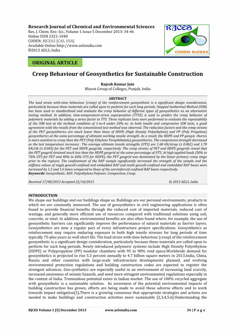
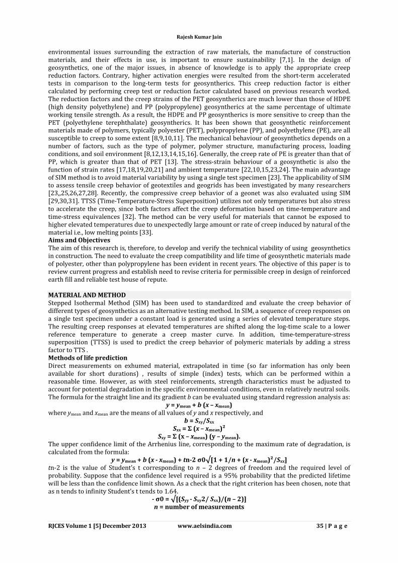
low inclined angle and applied stress ,whereas the secondary and tertiary creep stages were detected at high inclined angle and/or applied stress. The onset of the secondary creep stages was induced by the roll-over of upper ribs of the geonet. Thus, the geometry of the geonet, particularly the ribs, has a strong influence to the creep behavior (Figure 1 and 2).
Figure-1-Single geocell-confined and embedded
Figure-2-Multi geocell-confined and embedded
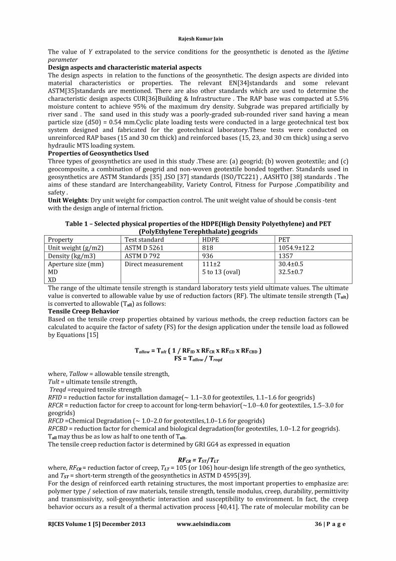
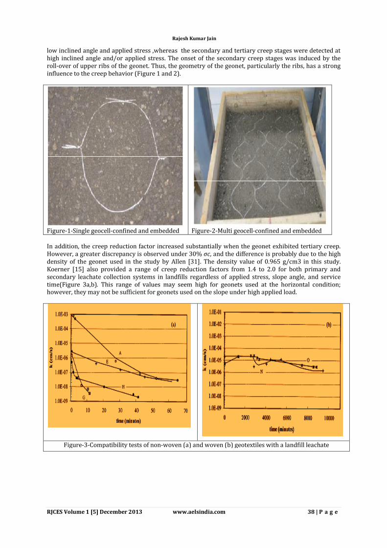
In addition, the creep reduction factor increased substantially when the geonet exhibited tertiary creep. However, a greater discrepancy is observed under 30% σc, and the difference is probably due to the high density of the geonet used in the study by Allen [31]. The density value of 0.965 g/cm3 in this study. Koerner [15] also provided a range of creep reduction factors from 1.4 to 2.0 for both primary and secondary leachate collection systems in landfills regardless of applied stress, slope angle, and service time(Figure 3a,b). This range of values may seem high for geonets used at the horizontal condition; however, they may not be sufficient for geonets used on the slope under high applied load.
Figure-3-Compatibility tests of non-woven (a) and woven (b) geotextiles with a landfill leachate
Rajesh Kumar Jain
RJCES Volume 1 [5] December 2013 www.aelsindia.com 39 | P a g e
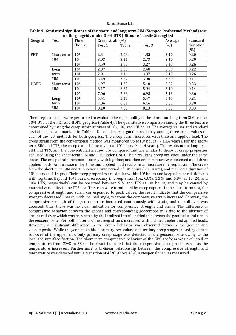
Table 4– Statistical significance of the short- and long-term SIM (Stepped Isothermal Method) test on the geogrids under 30% UTS (Ultimate Tensile Strengths)
Geogrid Test Time (hours)
Creep strain (%) Average (%)
Standard deviation (%)
Test 1 Test 2 Test 3
PET Short term SIM
101 2.31 2.08 1.85 2.10 0.20 103 3.03 3.11 2.73 3.10 0.20 105 3.59 3.87 3.27 3.43 0.26
Long term SIM
101 2.07 2.29 2.48 2.30 0.22 103 2.91 3.16 3.37 3.19 0.26 105 3.49 3.67 3.90 3.69 0.17
HDPE Short term SIM
101 4.97 4.73 5.10 5.02 0.23 103 6.17 6.31 5.94 6.19 0.14 105 7.06 7.89 6.98 7.13 0.36
Long term SIM
101 5.41 5.17 5.47 5.45 0.21 103 7.06 6.61 6.46 6.61 0.30 105 8.10 7.68 8.13 8.03 0.33
Three replicate tests were performed to evaluate the repeatability of the short- and long-term SIM tests at 30% UTS of the PET and HDPE geogrids (Table 4). The quantitative comparison among the three test are determined by using the creep strain at times of 101, 103, and 105 hours. The average values and standard deviations are summarized in Table 4. Data indicates a good consistency among three creep values on each of the test methods for both geogrids. The creep strain increases with time and applied load. The creep strain from the conventional method was monitored up to104 hours (~ 1.14 years). For the short-term SIM and TTS, the creep extends linearly up to 106 hours (~ 114 years). The results of the long-term SIM and TTS, and the conventional method are compared and are similar to those of creep properties acquired using the short-term SIM and TTS under HALs. Their resulting creep are close under the same stress. The creep strain increases linearly with log time; and then creep rupture was detected at all three applied loads. An increase in log time and applied load results in an increase in creep strain. The creep from the short-term SIM and TTS cover a time period of 106 hours (~ 114 yrs), and reached a duration of 104 hours (~ 1.14 yrs). Their creep properties are similar within 104 hours and keep a linear relationship with log time. Beyond 104 hours, discrepancy in creep strain (i.e., 0.8%, 1.3%, and 0.8% at 10, 20, and 30% UTS, respectively) can be observed between SIM and TTS at 106 hours, and may be caused by material variability in the TTS test. The tests were terminated by creep rupture. In the short-term test, the compressive strength and strain corresponded to peak values, the result indicate that the compressive strength decreased linearly with inclined angle, whereas the compressive strain increased. Contrary, the compressive strength of the geocomposite increased continuously with strain, and no roll-over was detected; thus, there was no clear indication for compressive strength and strain. The difference of compressive behavior between the geonet and corresponding geocomposite is due to the absence of abrupt roll-over which was prevented by the localized interface friction between the geotextile and ribs in the geocomposite. For both materials, the creep strains increased with inclined angles and applied loads. However, a significant difference in the creep behavior was observed between the geonet and geocomposite. While the geonet exhibited primary, secondary, and tertiary creep stages caused by abrupt roll-over of the upper ribs, only primary creep stage was detected in the geocomposite owing to the localized interface friction. The short-term compressive behavior of the EPS geofoam was evaluated at temperatures from 23oC to 58oC. The result indicated that the compressive strength decreased as the temperature increases. Furthermore, a bi-linear relationship between the compressive strength and temperature was detected with a transition at 43oC. Above 43oC, a steeper slope was measured.
Rajesh Kumar Jain
RJCES Volume 1 [5] December 2013 www.aelsindia.com 40 | P a g e
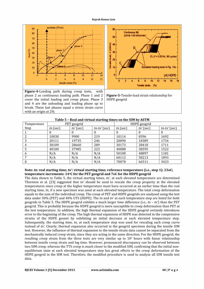
Figure-4-Loading path during creep tests, with phase 2 as continuous loading path. Phase 1 and 2 cover the initial loading and creep phase. Phase 3 and 4 are the unloading and loading phase up to break. These last phases equal a stress strain curve with an origin at 2%
Figure-5-Tensile-load strain relationship for HDPE geogrid
Table 5 – Real and virtual starting times on the SIM by ASTM
Temperature Step
PET geogrid HDPE geogrid tn (sec) tn’ (sec) tn-tn’ (sec) tn (sec) tn’ (sec) tn-tn’ (sec)
1 0 0 0 0 0 0 2 10030 9900 219 10114 8396 1692 3 20111 19735 246 20090 18389 1734 4 30109 28660 289 30173 28418 1711 5 40100 37985 223 40088 38595 1522 6 N/A N/A N/A 50108 48897 1181 7 N/A N/A N/A 60112 58213 1893 8 N/A N/A N/A 70078 66511 3423 Note: tn: real starting time; tn’: virtual starting time; reference temperature (i.e., step 1): 23oC; temperature increments: 14oC for the PET geogrid and 7oC for the HDPE geogrid The data shown in Table 5, the virtual starting times, tn’, at each elevated temperature are determined Thornton et al. [23] suggested that tn’ should be used to rescale the creep property at the elevated temperatures since creep at the higher temperature must have occurred at an earlier time than the real starting time, tn, if a new specimen was used at each elevated temperature. The total creep deformation equals to the sum of the individual creep. The creep of PET and HDPE geogrids are analysed using the test data under 50% (PET) and 40% UTS (HDPE). The tn and tn’ at each temperature step are listed for both geogrids in Table 5. The HDPE geogrid exhibits a much larger time difference (i.e., tn – tn’) than the PET geogrid. This is probably because the HDPE geogrid is more susceptible to creep deformation than PET at the test temperature. In addition, the high thermal expansion of the HDPE geogrid certainly introduces error to the beginning of the creep. The high thermal expansion of HDPE was detected in the compressive strains of the HDPE geonet by exhibiting an initial decrease at each elevated temperature step. Subsequently, the starting time, tn, at each temperature step was used for rescaling each creep curve instead of tn’. Clearly, thermal expansion also occurred in the geogrid specimen during the tensile SIM test. However, the influence of thermal expansion to the tensile strain data cannot be separated from the mechanically induced creep strain, since they are acting in the same direction. For the HDPE geogrid, the resulting creep strain from the three tests are very similar up to 103 hours with linear relationship between tensile creep strain and log time. However, pronounced discrepancy can be observed between two SIM creep, whereas the TTS creep is much closer to the modified SIM, confirming that the initial non-equilibrium state at each elevated temperature step has great effects to the creep deformation of the HDPE geogrid in the SIM test. Therefore, the modified procedure is used to analyze all SIM tensile test data.
Rajesh Kumar Jain
RJCES Volume 1 [5] December 2013 www.aelsindia.com 41 | P a g e
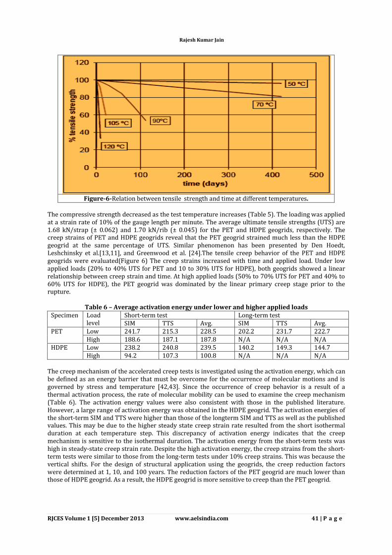
Figure-6-Relation between tensile strength and time at different temperatures.
The compressive strength decreased as the test temperature increases (Table 5). The loading was applied at a strain rate of 10% of the gauge length per minute. The average ultimate tensile strengths (UTS) are 1.68 kN/strap (± 0.062) and 1.70 kN/rib (± 0.045) for the PET and HDPE geogrids, respectively. The creep strains of PET and HDPE geogrids reveal that the PET geogrid strained much less than the HDPE geogrid at the same percentage of UTS. Similar phenomenon has been presented by Den Hoedt, Leshchinsky et al.[13,11], and Greenwood et al. [24].The tensile creep behavior of the PET and HDPE geogrids were evaluated(Figure 6) The creep strains increased with time and applied load. Under low applied loads (20% to 40% UTS for PET and 10 to 30% UTS for HDPE), both geogrids showed a linear relationship between creep strain and time. At high applied loads (50% to 70% UTS for PET and 40% to 60% UTS for HDPE), the PET geogrid was dominated by the linear primary creep stage prior to the rupture.
Table 6 – Average activation energy under lower and higher applied loads Specimen Load
level Short-term test Long-term test SIM TTS Avg. SIM TTS Avg.
PET Low 241.7 215.3 228.5 202.2 231.7 222.7 High 188.6 187.1 187.8 N/A N/A N/A
HDPE Low 238.2 240.8 239.5 140.2 149.3 144.7 High 94.2 107.3 100.8 N/A N/A N/A
The creep mechanism of the accelerated creep tests is investigated using the activation energy, which can be defined as an energy barrier that must be overcome for the occurrence of molecular motions and is governed by stress and temperature [42,43]. Since the occurrence of creep behavior is a result of a thermal activation process, the rate of molecular mobility can be used to examine the creep mechanism (Table 6). The activation energy values were also consistent with those in the published literature. However, a large range of activation energy was obtained in the HDPE geogrid. The activation energies of the short-term SIM and TTS were higher than those of the longterm SIM and TTS as well as the published values. This may be due to the higher steady state creep strain rate resulted from the short isothermal duration at each temperature step. This discrepancy of activation energy indicates that the creep mechanism is sensitive to the isothermal duration. The activation energy from the short-term tests was high in steady-state creep strain rate. Despite the high activation energy, the creep strains from the short-term tests were similar to those from the long-term tests under 10% creep strains. This was because the vertical shifts. For the design of structural application using the geogrids, the creep reduction factors were determined at 1, 10, and 100 years. The reduction factors of the PET geogrid are much lower than those of HDPE geogrid. As a result, the HDPE geogrid is more sensitive to creep than the PET geogrid.
Rajesh Kumar Jain
RJCES Volume 1 [5] December 2013 www.aelsindia.com 42 | P a g e
Table 7– Creep reduction factors of this study for the PET and HDPE geogrids Time (years)
Study (2012) PET HDPE
10% strain Rupture SIM TTS SIM TTS SIM TTS
1 1.41 1.35 3.29 3.49 2.18 2.05 11 1.74 1.57 4.18 4.42 2.49 2.27 114 2.08 1.81 5.44 6.04 2.90 2.55
The creep reduction factors are calculated and summarized in Table 7. The creep reduction factors obtained from the short-term SIM and TTS tests are relatively similar for both geogrids. However, as design time increases, the discrepancy of the creep reduction factor between this study and published values increases. For the HDPE geonet and geocomposite, the reduction factors increased with inclined angle, applied stress, and creep time. Their reduction factors were close at lower inclined angles and/or load conditions. Contrary, the reduction factor of geonet was much greater than that of geocomposite at higher inclined angles and/or load conditions due to the occurrence of tertiary creep stage in the geonet(Figure 7 and 8). For the PET and HDPE geogrids, the reduction factors increased with creep time. The HDPE geogrid yielded much greater reduction factor than the PET geogrid. Based on the results of creep tests, the creep reduction factors were obtained for the design applications. For the HDPE geonet and geocomposite, the reduction factors increased with inclined angle, applied stress, and creep time. Their reduction factors were close at lower inclined angles and/or load conditions. Contrary, the reduction factor of geonet was much greater than that of geocomposite at higher inclined angles and/or load conditions due to the occurrence of tertiary creep stage in the geonet. For the PET and HDPE geogrids, the reduction factors increased with creep time. The HDPE geogrid yielded much greater reduction factor than the PET geogrid.
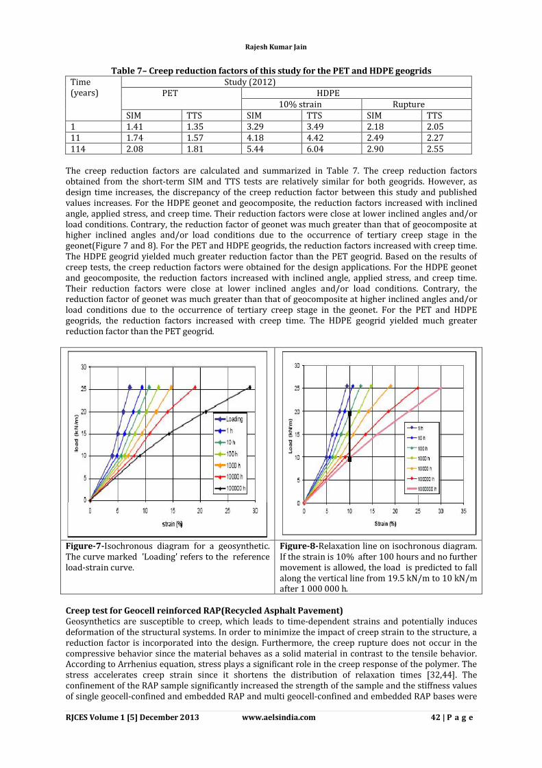
Figure-7-Isochronous diagram for a geosynthetic. The curve marked 'Loading' refers to the reference load-strain curve.
Figure-8-Relaxation line on isochronous diagram. If the strain is 10% after 100 hours and no further movement is allowed, the load is predicted to fall along the vertical line from 19.5 kN/m to 10 kN/m after 1 000 000 h.
Creep test for Geocell reinforced RAP(Recycled Asphalt Pavement) Geosynthetics are susceptible to creep, which leads to time-dependent strains and potentially induces deformation of the structural systems. In order to minimize the impact of creep strain to the structure, a reduction factor is incorporated into the design. Furthermore, the creep rupture does not occur in the compressive behavior since the material behaves as a solid material in contrast to the tensile behavior. According to Arrhenius equation, stress plays a significant role in the creep response of the polymer. The stress accelerates creep strain since it shortens the distribution of relaxation times [32,44]. The confinement of the RAP sample significantly increased the strength of the sample and the stiffness values of single geocell-confined and embedded RAP and multi geocell-confined and embedded RAP bases were
Rajesh Kumar Jain
RJCES Volume 1 [5] December 2013 www.aelsindia.com 43 | P a g e
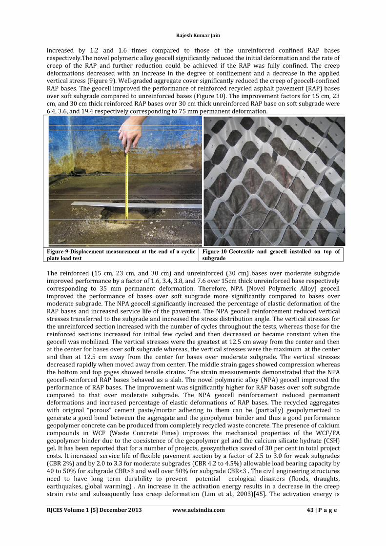
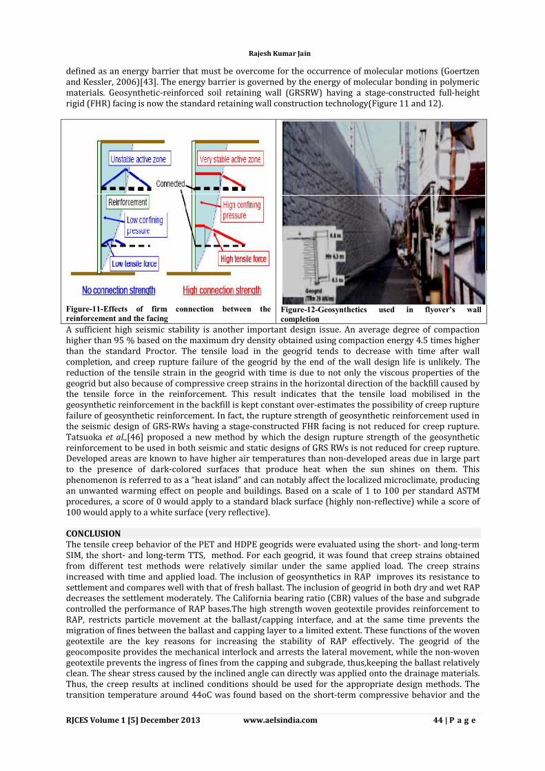
increased by 1.2 and 1.6 times compared to those of the unreinforced confined RAP bases respectively.The novel polymeric alloy geocell significantly reduced the initial deformation and the rate of creep of the RAP and further reduction could be achieved if the RAP was fully confined. The creep deformations decreased with an increase in the degree of confinement and a decrease in the applied vertical stress (Figure 9). Well-graded aggregate cover significantly reduced the creep of geocell-confined RAP bases. The geocell improved the performance of reinforced recycled asphalt pavement (RAP) bases over soft subgrade compared to unreinforced bases (Figure 10). The improvement factors for 15 cm, 23 cm, and 30 cm thick reinforced RAP bases over 30 cm thick unreinforced RAP base on soft subgrade were 6.4, 3.6, and 19.4 respectively corresponding to 75 mm permanent deformation.
Figure-9-Displacement measurement at the end of a cyclic plate load test
Figure-10-Geotextile and geocell installed on top of subgrade
The reinforced (15 cm, 23 cm, and 30 cm) and unreinforced (30 cm) bases over moderate subgrade improved performance by a factor of 1.6, 3.4, 3.8, and 7.6 over 15cm thick unreinforced base respectively corresponding to 35 mm permanent deformation. Therefore, NPA (Novel Polymeric Alloy) geocell improved the performance of bases over soft subgrade more significantly compared to bases over moderate subgrade. The NPA geocell significantly increased the percentage of elastic deformation of the RAP bases and increased service life of the pavement. The NPA geocell reinforcement reduced vertical stresses transferred to the subgrade and increased the stress distribution angle. The vertical stresses for the unreinforced section increased with the number of cycles throughout the tests, whereas those for the reinforced sections increased for initial few cycled and then decreased or became constant when the geocell was mobilized. The vertical stresses were the greatest at 12.5 cm away from the center and then at the center for bases over soft subgrade whereas, the vertical stresses were the maximum at the center and then at 12.5 cm away from the center for bases over moderate subgrade. The vertical stresses decreased rapidly when moved away from center. The middle strain gages showed compression whereas the bottom and top gages showed tensile strains. The strain measurements demonstrated that the NPA geocell-reinforced RAP bases behaved as a slab. The novel polymeric alloy (NPA) geocell improved the performance of RAP bases. The improvement was significantly higher for RAP bases over soft subgrade compared to that over moderate subgrade. The NPA geocell reinforcement reduced permanent deformations and increased percentage of elastic deformations of RAP bases. The recycled aggregates with original “porous” cement paste/mortar adhering to them can be (partially) geopolymerized to generate a good bond between the aggregate and the geopolymer binder and thus a good performance geopolymer concrete can be produced from completely recycled waste concrete. The presence of calcium compounds in WCF (Waste Concrete Fines) improves the mechanical properties of the WCF/FA geopolymer binder due to the coexistence of the geopolymer gel and the calcium silicate hydrate (CSH) gel. It has been reported that for a number of projects, geosynthetics saved of 30 per cent in total project costs. It increased service life of flexible pavement section by a factor of 2.5 to 3.0 for weak subgrades (CBR 2%) and by 2.0 to 3.3 for moderate subgrades (CBR 4.2 to 4.5%) allowable load bearing capacity by 40 to 50% for subgrade CBR>3 and well over 50% for subgrade CBR<3 . The civil engineering structures need to have long term durability to prevent potential ecological disasters (floods, draughts, earthquakes, global warming) . An increase in the activation energy results in a decrease in the creep strain rate and subsequently less creep deformation (Lim et al., 2003)[45]. The activation energy is
Rajesh Kumar Jain
RJCES Volume 1 [5] December 2013 www.aelsindia.com 44 | P a g e
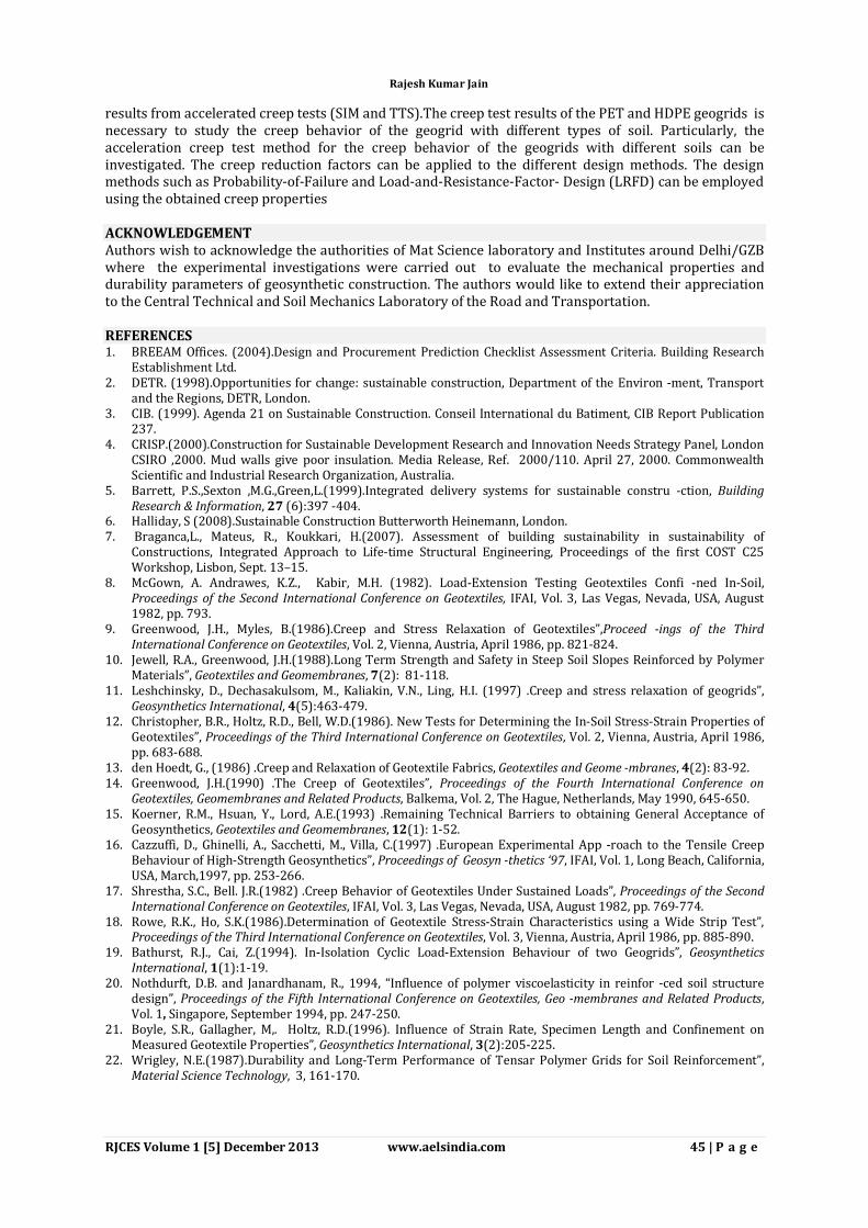
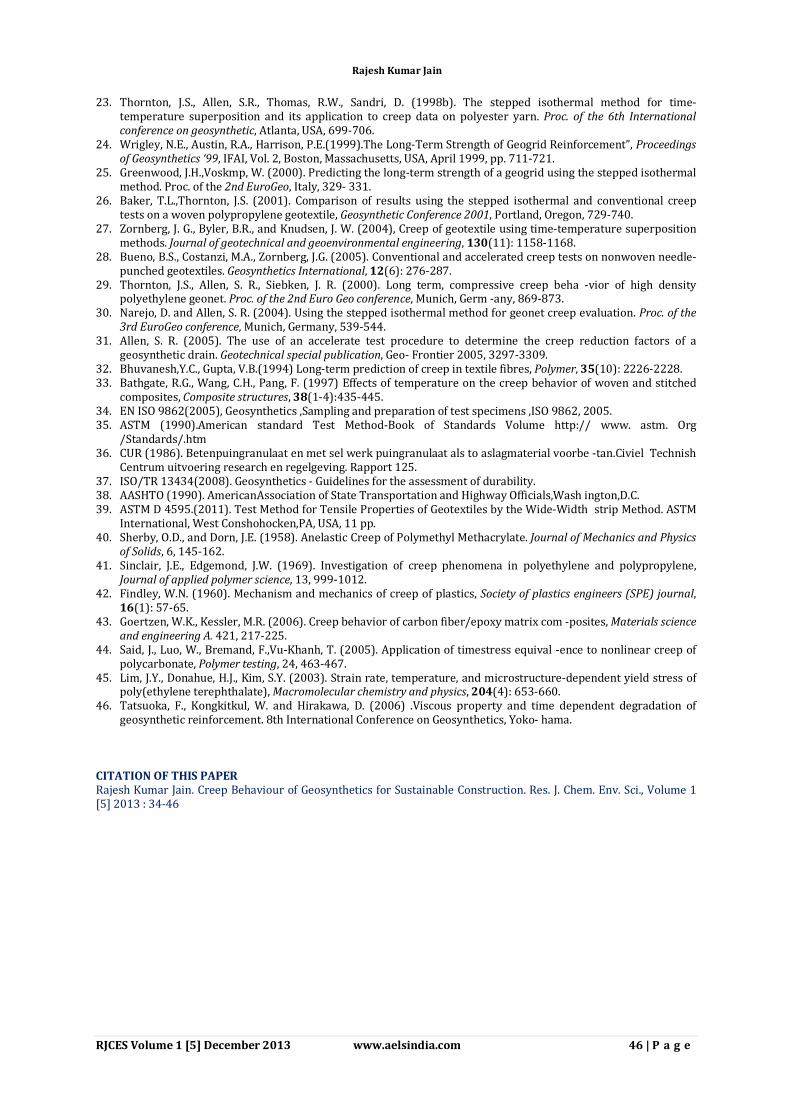
defined as an energy barrier that must be overcome for the occurrence of molecular motions (Goertzen and Kessler, 2006)[43]. The energy barrier is governed by the energy of molecular bonding in polymeric materials. Geosynthetic-reinforced soil retaining wall (GRSRW) having a stage-constructed full-height rigid (FHR) facing is now the standard retaining wall construction technology(Figure 11 and 12).
Figure-11-Effects of firm connection between the reinforcement and the facing
Figure-12-Geosynthetics used in flyover's wall completion
A sufficient high seismic stability is another important design issue. An average degree of compaction higher than 95 % based on the maximum dry density obtained using compaction energy 4.5 times higher than the standard Proctor. The tensile load in the geogrid tends to decrease with time after wall completion, and creep rupture failure of the geogrid by the end of the wall design life is unlikely. The reduction of the tensile strain in the geogrid with time is due to not only the viscous properties of the geogrid but also because of compressive creep strains in the horizontal direction of the backfill caused by the tensile force in the reinforcement. This result indicates that the tensile load mobilised in the geosynthetic reinforcement in the backfill is kept constant over-estimates the possibility of creep rupture failure of geosynthetic reinforcement. In fact, the rupture strength of geosynthetic reinforcement used in the seismic design of GRS-RWs having a stage-constructed FHR facing is not reduced for creep rupture. Tatsuoka et al.,[46] proposed a new method by which the design rupture strength of the geosynthetic reinforcement to be used in both seismic and static designs of GRS RWs is not reduced for creep rupture. Developed areas are known to have higher air temperatures than non-developed areas due in large part to the presence of dark-colored surfaces that produce heat when the sun shines on them. This phenomenon is referred to as a “heat island” and can notably affect the localized microclimate, producing an unwanted warming effect on people and buildings. Based on a scale of 1 to 100 per standard ASTM procedures, a score of 0 would apply to a standard black surface (highly non-reflective) while a score of 100 would apply to a white surface (very reflective). CONCLUSION The tensile creep behavior of the PET and HDPE geogrids were evaluated using the short- and long-term SIM, the short- and long-term TTS, method. For each geogrid, it was found that creep strains obtained from different test methods were relatively similar under the same applied load. The creep strains increased with time and applied load. The inclusion of geosynthetics in RAP improves its resistance to settlement and compares well with that of fresh ballast. The inclusion of geogrid in both dry and wet RAP decreases the settlement moderately. The California bearing ratio (CBR) values of the base and subgrade controlled the performance of RAP bases.The high strength woven geotextile provides reinforcement to RAP, restricts particle movement at the ballast/capping interface, and at the same time prevents the migration of fines between the ballast and capping layer to a limited extent. These functions of the woven geotextile are the key reasons for increasing the stability of RAP effectively. The geogrid of the geocomposite provides the mechanical interlock and arrests the lateral movement, while the non-woven geotextile prevents the ingress of fines from the capping and subgrade, thus,keeping the ballast relatively clean. The shear stress caused by the inclined angle can directly was applied onto the drainage materials. Thus, the creep results at inclined conditions should be used for the appropriate design methods. The transition temperature around 44oC was found based on the short-term compressive behavior and the
Rajesh Kumar Jain
RJCES Volume 1 [5] December 2013 www.aelsindia.com 45 | P a g e
results from accelerated creep tests (SIM and TTS).The creep test results of the PET and HDPE geogrids is necessary to study the creep behavior of the geogrid with different types of soil. Particularly, the acceleration creep test method for the creep behavior of the geogrids with different soils can be investigated. The creep reduction factors can be applied to the different design methods. The design methods such as Probability-of-Failure and Load-and-Resistance-Factor- Design (LRFD) can be employed using the obtained creep properties ACKNOWLEDGEMENT Authors wish to acknowledge the authorities of Mat Science laboratory and Institutes around Delhi/GZB where the experimental investigations were carried out to evaluate the mechanical properties and durability parameters of geosynthetic construction. The authors would like to extend their appreciation to the Central Technical and Soil Mechanics Laboratory of the Road and Transportation. REFERENCES 1. BREEAM Offices. (2004).Design and Procurement Prediction Checklist Assessment Criteria. Building Research
Establishment Ltd. 2. DETR. (1998).Opportunities for change: sustainable construction, Department of the Environ -ment, Transport
and the Regions, DETR, London. 3. CIB. (1999). Agenda 21 on Sustainable Construction. Conseil International du Batiment, CIB Report Publication
237. 4. CRISP.(2000).Construction for Sustainable Development Research and Innovation Needs Strategy Panel, London
CSIRO ,2000. Mud walls give poor insulation. Media Release, Ref. 2000/110. April 27, 2000. Commonwealth Scientific and Industrial Research Organization, Australia.
5. Barrett, P.S.,Sexton ,M.G.,Green,L.(1999).Integrated delivery systems for sustainable constru -ction, Building Research & Information, 27 (6):397 -404.
6. Halliday, S (2008).Sustainable Construction Butterworth Heinemann, London. 7. Braganca,L., Mateus, R., Koukkari, H.(2007). Assessment of building sustainability in sustainability of
Constructions, Integrated Approach to Life-time Structural Engineering, Proceedings of the first COST C25 Workshop, Lisbon, Sept. 13–15.
8. McGown, A. Andrawes, K.Z., Kabir, M.H. (1982). Load-Extension Testing Geotextiles Confi -ned In-Soil, Proceedings of the Second International Conference on Geotextiles, IFAI, Vol. 3, Las Vegas, Nevada, USA, August 1982, pp. 793.
9. Greenwood, J.H., Myles, B.(1986).Creep and Stress Relaxation of Geotextiles”,Proceed -ings of the Third International Conference on Geotextiles, Vol. 2, Vienna, Austria, April 1986, pp. 821-824.
10. Jewell, R.A., Greenwood, J.H.(1988).Long Term Strength and Safety in Steep Soil Slopes Reinforced by Polymer Materials”, Geotextiles and Geomembranes, 7(2): 81-118.
11. Leshchinsky, D., Dechasakulsom, M., Kaliakin, V.N., Ling, H.I. (1997) .Creep and stress relaxation of geogrids”, Geosynthetics International, 4(5):463-479.
12. Christopher, B.R., Holtz, R.D., Bell, W.D.(1986). New Tests for Determining the In-Soil Stress-Strain Properties of Geotextiles”, Proceedings of the Third International Conference on Geotextiles, Vol. 2, Vienna, Austria, April 1986, pp. 683-688.
13. den Hoedt, G., (1986) .Creep and Relaxation of Geotextile Fabrics, Geotextiles and Geome -mbranes, 4(2): 83-92. 14. Greenwood, J.H.(1990) .The Creep of Geotextiles”, Proceedings of the Fourth International Conference on
Geotextiles, Geomembranes and Related Products, Balkema, Vol. 2, The Hague, Netherlands, May 1990, 645-650. 15. Koerner, R.M., Hsuan, Y., Lord, A.E.(1993) .Remaining Technical Barriers to obtaining General Acceptance of
Geosynthetics, Geotextiles and Geomembranes, 12(1): 1-52. 16. Cazzuffi, D., Ghinelli, A., Sacchetti, M., Villa, C.(1997) .European Experimental App -roach to the Tensile Creep
Behaviour of High-Strength Geosynthetics”, Proceedings of Geosyn -thetics ‘97, IFAI, Vol. 1, Long Beach, California, USA, March,1997, pp. 253-266.
17. Shrestha, S.C., Bell. J.R.(1982) .Creep Behavior of Geotextiles Under Sustained Loads”, Proceedings of the Second International Conference on Geotextiles, IFAI, Vol. 3, Las Vegas, Nevada, USA, August 1982, pp. 769-774.
18. Rowe, R.K., Ho, S.K.(1986).Determination of Geotextile Stress-Strain Characteristics using a Wide Strip Test”, Proceedings of the Third International Conference on Geotextiles, Vol. 3, Vienna, Austria, April 1986, pp. 885-890.
19. Bathurst, R.J., Cai, Z.(1994). In-Isolation Cyclic Load-Extension Behaviour of two Geogrids”, Geosynthetics International, 1(1):1-19.
20. Nothdurft, D.B. and Janardhanam, R., 1994, “Influence of polymer viscoelasticity in reinfor -ced soil structure design”, Proceedings of the Fifth International Conference on Geotextiles, Geo -membranes and Related Products, Vol. 1, Singapore, September 1994, pp. 247-250.
21. Boyle, S.R., Gallagher, M,. Holtz, R.D.(1996). Influence of Strain Rate, Specimen Length and Confinement on Measured Geotextile Properties”, Geosynthetics International, 3(2):205-225.
22. Wrigley, N.E.(1987).Durability and Long-Term Performance of Tensar Polymer Grids for Soil Reinforcement”, Material Science Technology, 3, 161-170.
Rajesh Kumar Jain
RJCES Volume 1 [5] December 2013 www.aelsindia.com 46 | P a g e
23. Thornton, J.S., Allen, S.R., Thomas, R.W., Sandri, D. (1998b). The stepped isothermal method for time-temperature superposition and its application to creep data on polyester yarn. Proc. of the 6th International conference on geosynthetic, Atlanta, USA, 699-706.
24. Wrigley, N.E., Austin, R.A., Harrison, P.E.(1999).The Long-Term Strength of Geogrid Reinforcement”, Proceedings of Geosynthetics ‘99, IFAI, Vol. 2, Boston, Massachusetts, USA, April 1999, pp. 711-721.
25. Greenwood, J.H.,Voskmp, W. (2000). Predicting the long-term strength of a geogrid using the stepped isothermal method. Proc. of the 2nd EuroGeo, Italy, 329- 331.
26. Baker, T.L.,Thornton, J.S. (2001). Comparison of results using the stepped isothermal and conventional creep tests on a woven polypropylene geotextile, Geosynthetic Conference 2001, Portland, Oregon, 729-740.
27. Zornberg, J. G., Byler, B.R., and Knudsen, J. W. (2004), Creep of geotextile using time-temperature superposition methods. Journal of geotechnical and geoenvironmental engineering, 130(11): 1158-1168.
28. Bueno, B.S., Costanzi, M.A., Zornberg, J.G. (2005). Conventional and accelerated creep tests on nonwoven needle-punched geotextiles. Geosynthetics International, 12(6): 276-287.
29. Thornton, J.S., Allen, S. R., Siebken, J. R. (2000). Long term, compressive creep beha -vior of high density polyethylene geonet. Proc. of the 2nd Euro Geo conference, Munich, Germ -any, 869-873.
30. Narejo, D. and Allen, S. R. (2004). Using the stepped isothermal method for geonet creep evaluation. Proc. of the 3rd EuroGeo conference, Munich, Germany, 539-544.
31. Allen, S. R. (2005). The use of an accelerate test procedure to determine the creep reduction factors of a geosynthetic drain. Geotechnical special publication, Geo- Frontier 2005, 3297-3309.
32. Bhuvanesh,Y.C., Gupta, V.B.(1994) Long-term prediction of creep in textile fibres, Polymer, 35(10): 2226-2228. 33. Bathgate, R.G., Wang, C.H., Pang, F. (1997) Effects of temperature on the creep behavior of woven and stitched
composites, Composite structures, 38(1-4):435-445. 34. EN ISO 9862(2005), Geosynthetics ,Sampling and preparation of test specimens ,ISO 9862, 2005. 35. ASTM (1990).American standard Test Method-Book of Standards Volume http:// www. astm. Org
/Standards/.htm 36. CUR (1986). Betenpuingranulaat en met sel werk puingranulaat als to aslagmaterial voorbe -tan.Civiel Technish
Centrum uitvoering research en regelgeving. Rapport 125. 37. ISO/TR 13434(2008). Geosynthetics - Guidelines for the assessment of durability. 38. AASHTO (1990). AmericanAssociation of State Transportation and Highway Officials,Wash ington,D.C. 39. ASTM D 4595.(2011). Test Method for Tensile Properties of Geotextiles by the Wide-Width strip Method. ASTM
International, West Conshohocken,PA, USA, 11 pp. 40. Sherby, O.D., and Dorn, J.E. (1958). Anelastic Creep of Polymethyl Methacrylate. Journal of Mechanics and Physics
of Solids, 6, 145-162. 41. Sinclair, J.E., Edgemond, J.W. (1969). Investigation of creep phenomena in polyethylene and polypropylene,
Journal of applied polymer science, 13, 999-1012. 42. Findley, W.N. (1960). Mechanism and mechanics of creep of plastics, Society of plastics engineers (SPE) journal,
16(1): 57-65. 43. Goertzen, W.K., Kessler, M.R. (2006). Creep behavior of carbon fiber/epoxy matrix com -posites, Materials science
and engineering A. 421, 217-225. 44. Said, J., Luo, W., Bremand, F.,Vu-Khanh, T. (2005). Application of timestress equival -ence to nonlinear creep of
polycarbonate, Polymer testing, 24, 463-467. 45. Lim, J.Y., Donahue, H.J., Kim, S.Y. (2003). Strain rate, temperature, and microstructure-dependent yield stress of
poly(ethylene terephthalate), Macromolecular chemistry and physics, 204(4): 653-660. 46. Tatsuoka, F., Kongkitkul, W. and Hirakawa, D. (2006) .Viscous property and time dependent degradation of
geosynthetic reinforcement. 8th International Conference on Geosynthetics, Yoko- hama.
CITATION OF THIS PAPER Rajesh Kumar Jain. Creep Behaviour of Geosynthetics for Sustainable Construction. Res. J. Chem. Env. Sci., Volume 1 [5] 2013 : 34-46
Rajesh Kumar Jain