cree xlamp xm-l color led data sheet · of each led die within the xlamp xm-l color led ......
TRANSCRIPT
Product family data sheet
Copyright © 2012-2018 Cree, Inc. All rights reserved. The information in this document is subject to change without notice. Cree® and XLamp® are registered trademarks and the Cree logo and XM-L™ are trademarks of Cree, Inc. UL® and the UR logo are registered trademarks of UL LLC.
Cree, Inc.4600 Silicon Drive
Durham, NC 27703USA Tel: +1.919.313.5300
ww
w.C
Ree.
Co
M/X
LAM
pC
LD-D
S58 Rev
5D
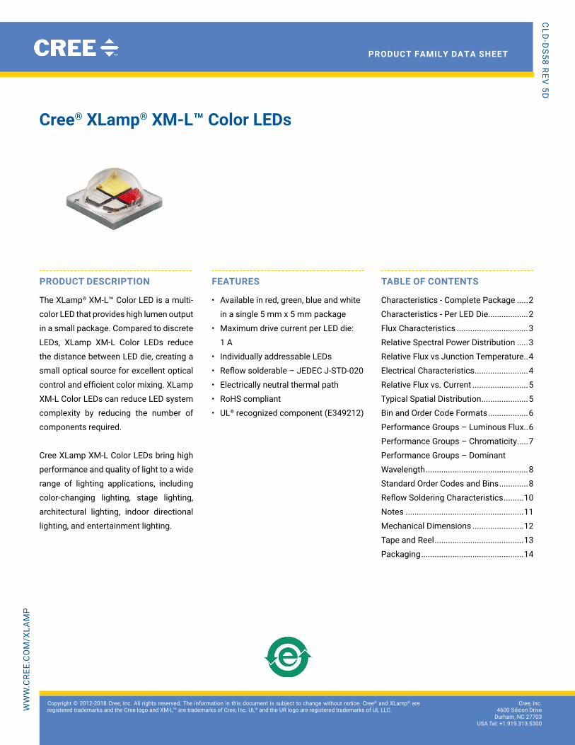
Cree® XLamp® XM-L™ Color LEDs
ProDuCt DEsCriPtion
The XLamp® XM-L™ Color LeD is a multi-
color LeD that provides high lumen output
in a small package. Compared to discrete
LeDs, XLamp XM-L Color LeDs reduce
the distance between LeD die, creating a
small optical source for excellent optical
control and efficient color mixing. XLamp
XM-L Color LeDs can reduce LeD system
complexity by reducing the number of
components required.
Cree XLamp XM-L Color LeDs bring high
performance and quality of light to a wide
range of lighting applications, including
color-changing lighting, stage lighting,
architectural lighting, indoor directional
lighting, and entertainment lighting.
FEAturEs
• Available in red, green, blue and white
in a single 5 mm x 5 mm package
• Maximum drive current per LeD die:
1 A
• Individually addressable LeDs
• Reflow solderable – JEDEC J-STD-020
• electrically neutral thermal path
• RoHS compliant
• UL® recognized component (E349212)
tAbLE oF ContEnts
Characteristics - Complete Package .....2
Characteristics - Per LeD Die..................2
Flux Characteristics ................................3
Relative Spectral Power Distribution .....3
Relative Flux vs Junction Temperature ..4
electrical Characteristics ........................4
Relative Flux vs. Current .........................5
Typical Spatial Distribution .....................5
Bin and Order Code Formats ..................6
Performance Groups – Luminous Flux..6
Performance Groups – Chromaticity .....7
Performance Groups – Dominant
Wavelength ..............................................8
Standard Order Codes and Bins .............8
Reflow Soldering Characteristics .........10
Notes .....................................................11
Mechanical Dimensions .......................12
Tape and Reel ........................................13
Packaging ..............................................14
Copyright © 2012-2018 Cree, Inc. All rights reserved. The information in this document is subject to change without notice. Cree® and XLamp® are registered trademarks and the Cree logo and XM-L™ are trademarks of Cree, Inc. UL® and the UR logo are registered trademarks of UL LLC.
2
XLamp® Xm-L™ CoLor LED
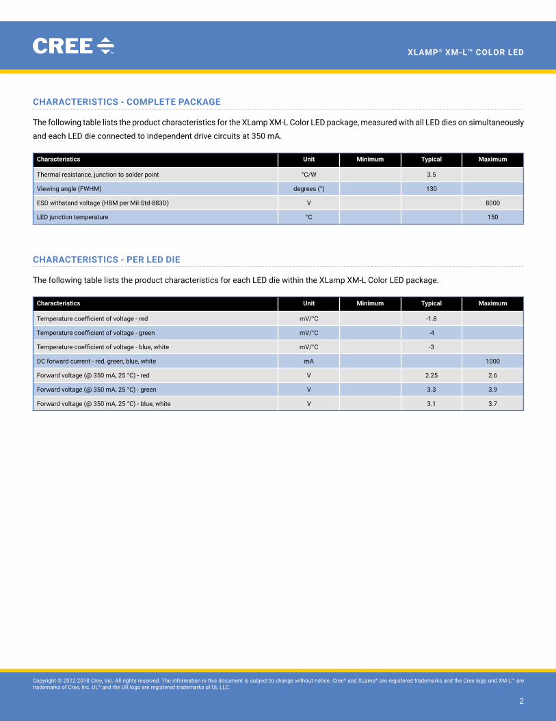
ChArACtEristiCs - CoMPLEtE PACkAgE
The following table lists the product characteristics for the XLamp XM-L Color LeD package, measured with all LeD dies on simultaneously
and each LED die connected to independent drive circuits at 350 mA.
Characteristics unit Minimum typical Maximum
Thermal resistance, junction to solder point °C/W 3.5
Viewing angle (FWHM) degrees (°) 130
ESD withstand voltage (HBM per Mil-Std-883D) v 8000
LeD junction temperature °C 150
ChArACtEristiCs - PEr LED DiE
The following table lists the product characteristics for each LeD die within the XLamp XM-L Color LeD package.
Characteristics unit Minimum typical Maximum
Temperature coefficient of voltage - red mv/°C -1.8
Temperature coefficient of voltage - green mv/°C -4
Temperature coefficient of voltage - blue, white mv/°C -3
DC forward current - red, green, blue, white mA 1000
Forward voltage (@ 350 mA, 25 °C) - red v 2.25 2.6
Forward voltage (@ 350 mA, 25 °C) - green v 3.3 3.9
Forward voltage (@ 350 mA, 25 °C) - blue, white v 3.1 3.7

Copyright © 2012-2018 Cree, Inc. All rights reserved. The information in this document is subject to change without notice. Cree® and XLamp® are registered trademarks and the Cree logo and XM-L™ are trademarks of Cree, Inc. UL® and the UR logo are registered trademarks of UL LLC.
3
XLamp® Xm-L™ CoLor LED
FLuX ChArACtEristiCs, (tJ = 25 °C)
The following tables provide several base order codes for XM-L Color LeDs. For a complete description of the order code nomenclature,
please refer to the Bin and Order Code Formats section (page 6).
ColorCCt / Dominant Wavelength range Minimum Luminous Flux
@ 350 mA order CodeMinimum Maximum group Flux (lm)
Color + Cool White
Red 620 nm 630 nm
C3
45.7
XMLCTW-A0-0000-00C3AAAA1Green 520 nm 535 nm 87.4
Blue 450 nm 465 nm 13.9
Cool White 5700 K 8000 K 100
Color + Neutral White
Red 620 nm 630 nm
C2
45.7
XMLCTW-A0-0000-00C2AAAB1Green 520 nm 535 nm 87.4
Blue 450 nm 465 nm 13.9
Neutral White 3700 K 4300 K 80
Color + Warm White
Red 620 nm 630 nm
C2
45.7
XMLCTW-A0-0000-00C2AAAC1Green 520 nm 535 nm 87.4
Blue 450 nm 465 nm 13.9
Warm White 2700 K 3700 K 80
Notes:• Cree maintains a tolerance of ±7% on flux and power measurements, ±0.005 on chromaticity (CCx, CCy) measurements and ±1 nm
on dominant wavelength measurements. See the Measurements section (page 11).• Flux and chromaticity are measured with each LED die connected to independent drive circuits at 350 mA. The flux and chromaticity
of each LeD die within the XLamp XM-L Color LeD package are measured individually.
rELAtivE sPECtrAL PoWEr Distribution (iF = 350 mA per LeD Die, 25 °C)
The following graph represents typical spectral output of the XLamp XM-L Color LeD with each LeD die on independently.
Relative Spectral Power Distribution (If = 350 mA per LED)The following graph represents typical spectral output of the XM-L RGBW Color LED with each LED on independently.White 3000 K data from XP-G3 (XPGD_Datasheet_160320.2nd-roboto.xlsx)
0%
20%
40%
60%
80%
100%
380 430 480 530 580 630 680 730 780
Rela
tive
Radi
ant P
ower
Wavelength (nm)
Red
Green
Blue
White 3000 K
White 4000 K
White 6000 K
Copyright © 2012-2018 Cree, Inc. All rights reserved. The information in this document is subject to change without notice. Cree® and XLamp® are registered trademarks and the Cree logo and XM-L™ are trademarks of Cree, Inc. UL® and the UR logo are registered trademarks of UL LLC.
4
XLamp® Xm-L™ CoLor LED
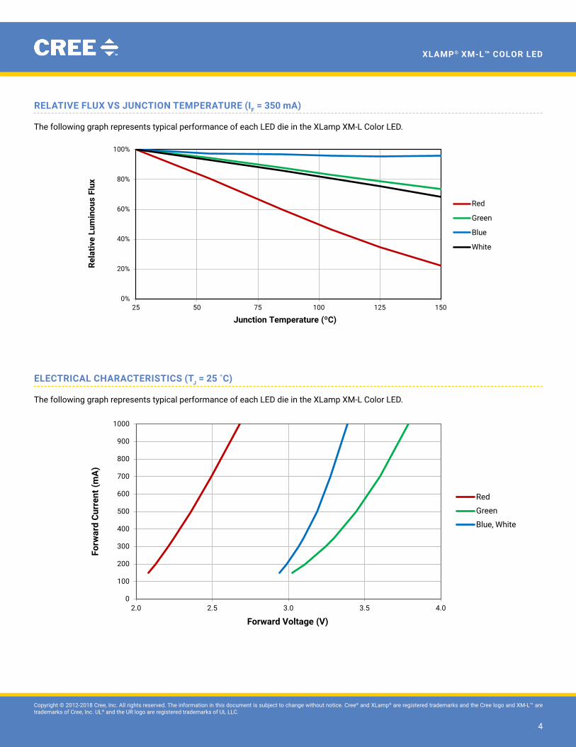
rELAtivE FLuX vs JunCtion tEMPErAturE (iF = 350 mA)
The following graph represents typical performance of each LeD die in the XLamp XM-L Color LeD.
ELECtriCAL ChArACtEristiCs (tJ = 25 ˚C)
The following graph represents typical performance of each LeD die in the XLamp XM-L Color LeD.
Relative Flux Output vs. Junction Temperature (If = 350 mA)The following graph represents typical performance of each LED die in the XM-L RGBW LED
0%
20%
40%
60%
80%
100%
25 50 75 100 125 150
Rela
tive
Lum
inou
s Fl
ux
Junction Temperature (ºC)
Red
Green
Blue
White
Electrical Characteristics (Tj = 25ºC)The following graph represents typical performance of each LED die in the XM-L RGBW LED
0
100
200
300
400
500
600
700
800
900
1000
2.0 2.5 3.0 3.5 4.0
Forw
ard
Curr
ent (
mA
)
Forward Voltage (V)
Red
Green
Blue, White
Copyright © 2012-2018 Cree, Inc. All rights reserved. The information in this document is subject to change without notice. Cree® and XLamp® are registered trademarks and the Cree logo and XM-L™ are trademarks of Cree, Inc. UL® and the UR logo are registered trademarks of UL LLC.
5
XLamp® Xm-L™ CoLor LED
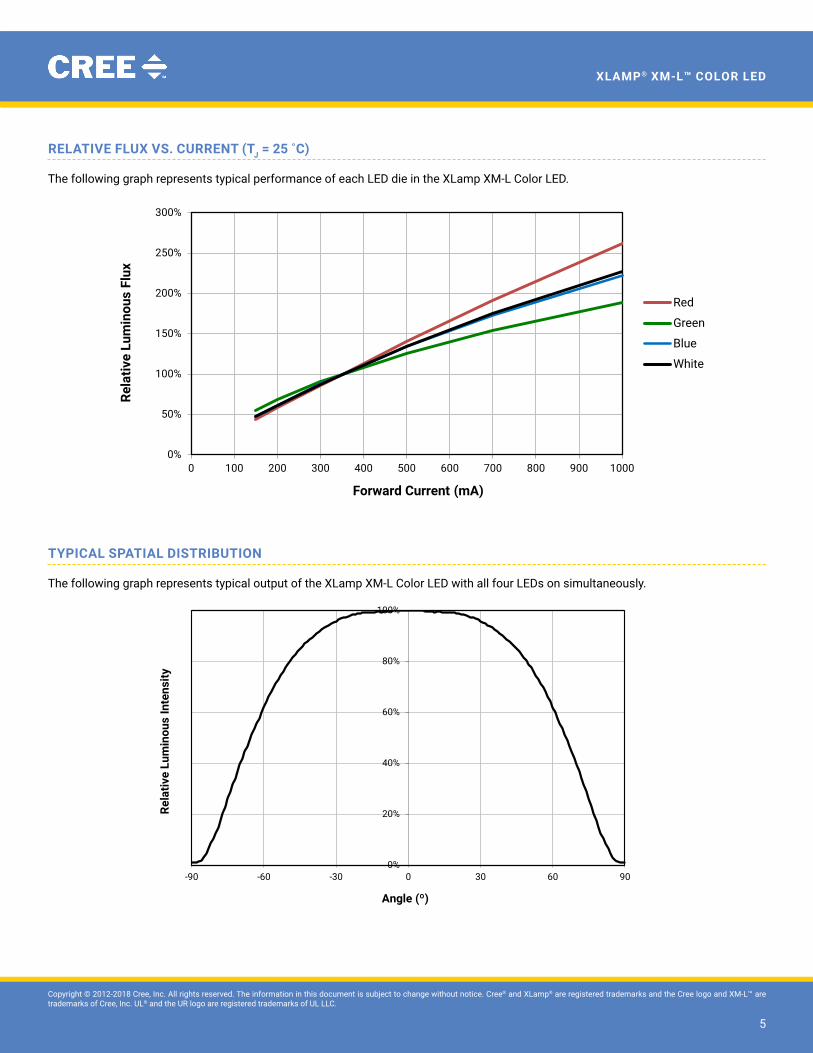
rELAtivE FLuX vs. CurrEnt (tJ = 25 ˚C)
The following graph represents typical performance of each LeD die in the XLamp XM-L Color LeD.
tyPiCAL sPAtiAL Distribution
The following graph represents typical output of the XLamp XM-L Color LeD with all four LeDs on simultaneously.
Relative Intensity vs. Current (Tj = 25ºC)
0%
50%
100%
150%
200%
250%
300%
0 100 200 300 400 500 600 700 800 900 1000
Rela
tive
Lum
inou
s Fl
ux
Forward Current (mA)
Red
Green
Blue
White
Typical Spatial Radiation PatternThe following graph represents typical spectral output of the XLamp MC-E LED with all four LEDs on simultaneously.
0%
20%
40%
60%
80%
100%
-90 -60 -30 0 30 60 90
Rela
tive
Lum
inou
s In
tens
ity
Angle (º)
Copyright © 2012-2018 Cree, Inc. All rights reserved. The information in this document is subject to change without notice. Cree® and XLamp® are registered trademarks and the Cree logo and XM-L™ are trademarks of Cree, Inc. UL® and the UR logo are registered trademarks of UL LLC.
6
XLamp® Xm-L™ CoLor LED
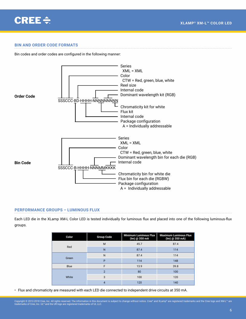
bin AnD orDEr CoDE ForMAts
Bin codes and order codes are configured in the following manner:
order Code
bin Code
PErForMAnCE grouPs – LuMinous FLuX
Each LED die in the XLamp XM-L Color LED is tested individually for luminous flux and placed into one of the following luminous-flux
groups.
Color group Code Minimum Luminous Flux (lm) @ 350 mA
Maximum Luminous Flux (lm) @ 350 mA)
RedM 45.7 87.4
N 87.4 114
GreenN 87.4 114
P 114 148
Blue F 13.9 39.8
White
2 80 100
3 100 120
4 120 140
• Flux and chromaticity are measured with each LED die connected to independent drive circuits at 350 mA.
SSSCCC-BD-HHHH-NNNNNNNNN
Series XML = XMLColor CTW = Red, green, blue, whiteReel sizeInternal codeDominant wavelength kit (RGB)
Chromaticity kit for whiteFlux kitInternal codePackage configuration A = Individually addressable
SSSCCC-B-HHHH-NNNMMKKKKChromaticity bin for white dieFlux bin for each die (RGBW)Package configuration A = Individually addressable
Series XML = XMLColor CTW = Red, green, blue, whiteDominant wavelength bin for each die (RGB)Internal code
Copyright © 2012-2018 Cree, Inc. All rights reserved. The information in this document is subject to change without notice. Cree® and XLamp® are registered trademarks and the Cree logo and XM-L™ are trademarks of Cree, Inc. UL® and the UR logo are registered trademarks of UL LLC.
7
XLamp® Xm-L™ CoLor LED
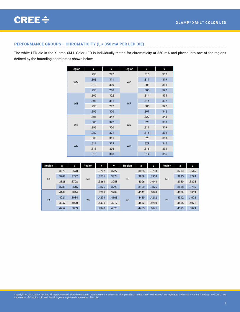
PErForMAnCE grouPs – ChroMAtiCity (iF = 350 mA per LeD Die)
The white LED die in the XLamp XM-L Color LED is individually tested for chromaticity at 350 mA and placed into one of the regions
defined by the bounding coordinates shown below.
region x y region x y
WM
.295 .297
WC
.316 .332
.308 .311 .317 .319
.310 .300 .308 .311
.298 .288 .306 .322
WB
.306 .322
WF
.314 .355
.308 .311 .316 .332
.295 .297 .306 .322
.292 .306 .301 .342
We
.301 .342
WD
.329 .345
.306 .322 .329 .330
.292 .306 .317 .319
.287 .321 .316 .332
WN
.308 .311
WG
.329 .369
.317 .319 .329 .345
.318 .308 .316 .332
.310 .300 .314 .355
region x y region x y region x y region x y
5A
.3670 .3578
5B
.3702 .3722
5C
.3825 .3798
5D
.3783 .3646
.3702 .3722 .3736 .3874 .3869 .3958 .3825 .3798
.3825 .3798 .3869 .3958 .4006 .4044 .3950 .3875
.3783 .3646 .3825 .3798 .3950 .3875 .3898 .3716
7A
.4147 .3814
7B
.4221 .3984
7C
.4342 .4028
7D
.4259 .3853
.4221 .3984 .4299 .4165 .4430 .4212 .4342 .4028
.4342 .4028 .4430 .4212 .4562 .4260 .4465 .4071
.4259 .3853 .4342 .4028 .4465 .4071 .4373 .3893
Copyright © 2012-2018 Cree, Inc. All rights reserved. The information in this document is subject to change without notice. Cree® and XLamp® are registered trademarks and the Cree logo and XM-L™ are trademarks of Cree, Inc. UL® and the UR logo are registered trademarks of UL LLC.
8
XLamp® Xm-L™ CoLor LED
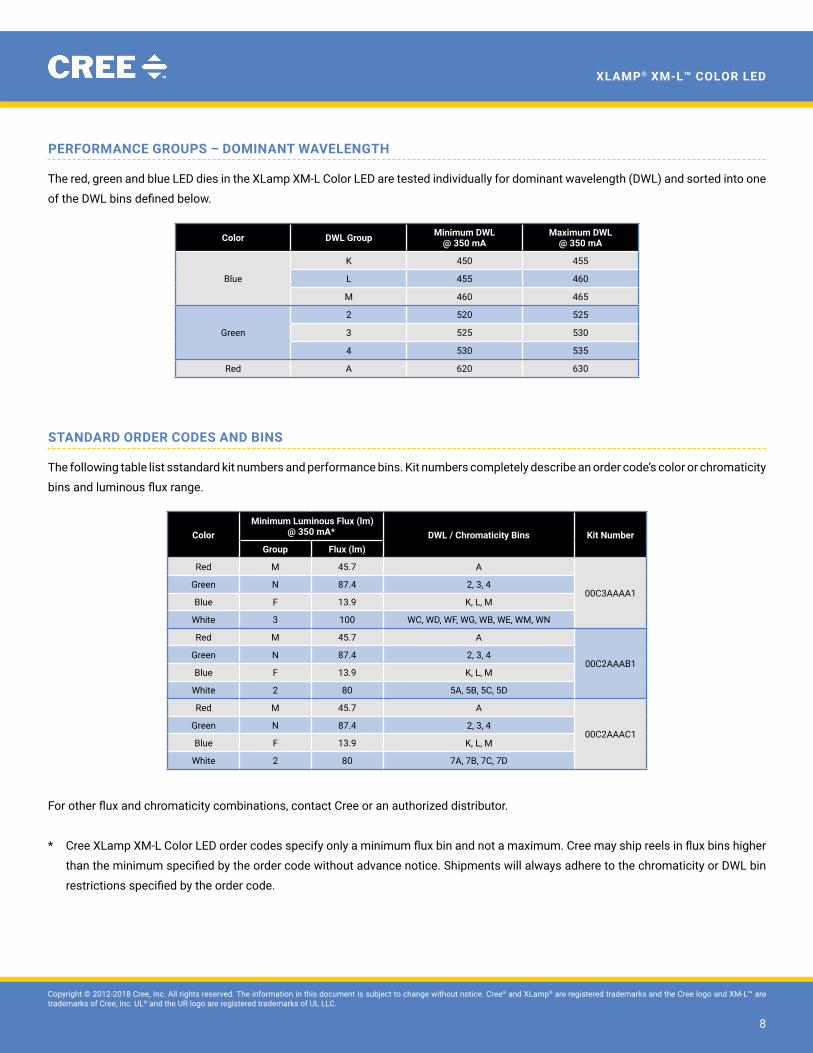
PErForMAnCE grouPs – DoMinAnt WAvELEngth
The red, green and blue LED dies in the XLamp XM-L Color LED are tested individually for dominant wavelength (DWL) and sorted into one
of the DWL bins defined below.
Color DWL group Minimum DWL@ 350 mA
Maximum DWL@ 350 mA
Blue
K 450 455
L 455 460
M 460 465
Green
2 520 525
3 525 530
4 530 535
Red A 620 630
stAnDArD orDEr CoDEs AnD bins
The following table list sstandard kit numbers and performance bins. Kit numbers completely describe an order code’s color or chromaticity
bins and luminous flux range.
Color Minimum Luminous Flux (lm)
@ 350 mA* DWL / Chromaticity bins kit numbergroup Flux (lm)
Red M 45.7 A
00C3AAAA1Green N 87.4 2, 3, 4
Blue F 13.9 K, L, M
White 3 100 WC, WD, WF, WG, WB, We, WM, WN
Red M 45.7 A
00C2AAAB1Green N 87.4 2, 3, 4
Blue F 13.9 K, L, M
White 2 80 5A, 5B, 5C, 5D
Red M 45.7 A
00C2AAAC1Green N 87.4 2, 3, 4
Blue F 13.9 K, L, M
White 2 80 7A, 7B, 7C, 7D
For other flux and chromaticity combinations, contact Cree or an authorized distributor.
* Cree XLamp XM-L Color LED order codes specify only a minimum flux bin and not a maximum. Cree may ship reels in flux bins higher
than the minimum specified by the order code without advance notice. Shipments will always adhere to the chromaticity or DWL bin
restrictions specified by the order code.
Copyright © 2012-2018 Cree, Inc. All rights reserved. The information in this document is subject to change without notice. Cree® and XLamp® are registered trademarks and the Cree logo and XM-L™ are trademarks of Cree, Inc. UL® and the UR logo are registered trademarks of UL LLC.
9
XLamp® Xm-L™ CoLor LED
2700 K3000 K
3500 K
4000 K4500 K
5000 K
5700 K
6500 K
8000 K
10000 K
WA
WB
WC
WD
WE
WF
WG
WH
WJ
WK
WM
WN
WP
3A
3B3C
3D4A
4B4C
4D5A
5B5C
5D6A
6B6C
6D7A
7B7C
7D 8A
8B 8C
8D
0.27
0.28
0.29
0.30
0.31
0.32
0.33
0.34
0.35
0.36
0.37
0.38
0.39
0.40
0.41
0.42
0.43
0.44
0.45
0.26
0.27
0.28
0.29
0.30
0.31
0.32
0.33
0.34
0.35
0.36
0.37
0.38
0.39
0.40
0.41
0.42
0.43
0.44
0.45
0.46
0.47
0.48
0.49
0.50
CCy
CCx
A1
B1
C1
stAnDArD orDEr CoDEs AnD bins - ContnuED
Copyright © 2012-2018 Cree, Inc. All rights reserved. The information in this document is subject to change without notice. Cree® and XLamp® are registered trademarks and the Cree logo and XM-L™ are trademarks of Cree, Inc. UL® and the UR logo are registered trademarks of UL LLC.
10
XLamp® Xm-L™ CoLor LED
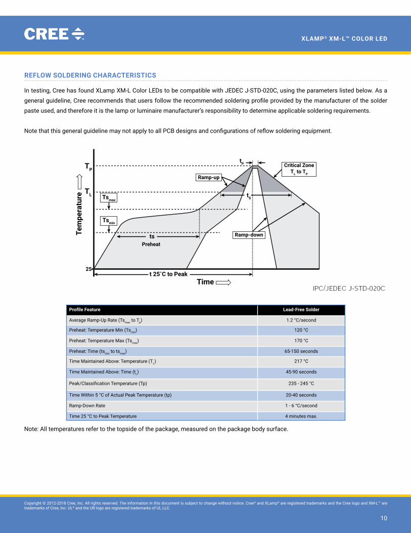
rEFLoW soLDEring ChArACtEristiCs
In testing, Cree has found XLamp XM-L Color LEDs to be compatible with JEDEC J-STD-020C, using the parameters listed below. As a
general guideline, Cree recommends that users follow the recommended soldering profile provided by the manufacturer of the solder
paste used, and therefore it is the lamp or luminaire manufacturer’s responsibility to determine applicable soldering requirements.
Note that this general guideline may not apply to all PCB designs and configurations of reflow soldering equipment.
Profile Feature Lead-Free solder
Average Ramp-Up Rate (Tsmax to Tp) 1.2 °C/second
Preheat: Temperature Min (Tsmin) 120 °C
Preheat: Temperature Max (Tsmax) 170 °C
Preheat: Time (tsmin to tsmax) 65-150 seconds
Time Maintained Above: Temperature (TL) 217 °C
Time Maintained Above: Time (tL) 45-90 seconds
Peak/Classification Temperature (Tp) 235 - 245 °C
Time Within 5 °C of Actual Peak Temperature (tp) 20-40 seconds
Ramp-Down Rate 1 - 6 °C/second
Time 25 °C to Peak Temperature 4 minutes max.
Note: All temperatures refer to the topside of the package, measured on the package body surface.
TP
TL
Tem
pera
ture
Timet 25˚C to Peak
Preheatts
tS
tP
25
Ramp-down
Ramp-up
Critical ZoneTL to TP
Tsmax
Tsmin
Copyright © 2012-2018 Cree, Inc. All rights reserved. The information in this document is subject to change without notice. Cree® and XLamp® are registered trademarks and the Cree logo and XM-L™ are trademarks of Cree, Inc. UL® and the UR logo are registered trademarks of UL LLC.
11
XLamp® Xm-L™ CoLor LED
notEs
MeasurementsThe luminous flux, radiant power, chromaticity, forward voltage and CRI measurements in this document are binning specifications only
and solely represent product measurements as of the date of shipment. These measurements will change over time based on a number
of factors that are not within Cree’s control and are not intended or provided as operational specifications for the products. Calculated
values are provided for informational purposes only and are not intended or provided as specifications.
pre‑release Qualification TestingPlease read the LeD Reliability Overview for details of the qualification process Cree applies to ensure long-term reliability for XLamp
LEDs and details of Cree’s pre-release qualification testing for XLamp LEDs.
rohs ComplianceThe levels of RoHS restricted materials in this product are below the maximum concentration values (also referred to as the threshold
limits) permitted for such substances, or are used in an exempted application, in accordance with EU Directive 2011/65/EC (RoHS2), as
implemented January 2, 2013. RoHS Declarations for this product can be obtained from your Cree representative or from the Product
ecology section of the Cree website.
uL® recognized ComponentThis product meets the requirements to be considered a UL Recognized Component with Level 4 enclosure consideration. The LeD
package or a portion thereof has been investigated as a fire and electrical enclosure per ANSI/UL 8750.
Copyright © 2012-2018 Cree, Inc. All rights reserved. The information in this document is subject to change without notice. Cree® and XLamp® are registered trademarks and the Cree logo and XM-L™ are trademarks of Cree, Inc. UL® and the UR logo are registered trademarks of UL LLC.
12
XLamp® Xm-L™ CoLor LED
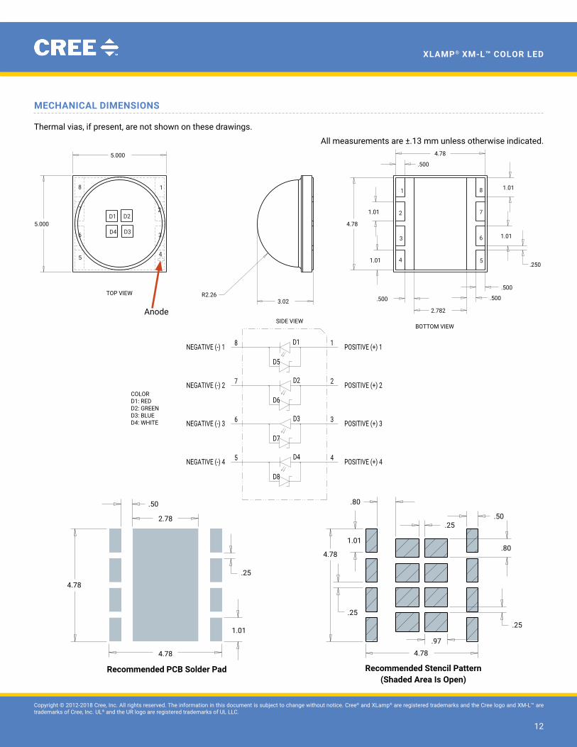
MEChAniCAL DiMEnsions
Thermal vias, if present, are not shown on these drawings.
All measurements are ±.13 mm unless otherwise indicated.
SIZE
TITLE
OF
REV.
SHEETC
DRAWING NO.
DATE
DATE
DATE
CHECK
FINAL PROTECTIVE FINISH
MATERIAL
APPROVED
DRAWN BY
THIRD ANGLE PROJECTION
SCALE
A
B
C
D
123456
6 5 4 3 2 1
A
B
C
D
Phone (919) 313-5300Fax (919) 313-5558
4600 Silicon DriveDurham, N.C 27703
UNAUTHORIZED PERSON WITHOUT THE WRITTEN CONSENTMAY NOT BE COPIED, REPRODUCED OR DISCLOSED TO ANY CONFIDENTIAL INFORMATION OF CREE, INC. THIS PLOT CONTAINED WITHIN ARE THE PROPRIETARY ANDCREE CONFIDENTIAL. THIS PLOT AND THE INFORMATION
OF CREE INC.
NOTICE
X° ± .5°.XXX ± .010.XX ± .03.X ± .06
FOR SHEET METAL PARTS ONLY
.XX ± .01
.XXX ± .005X° ± .5°
UNLESS OTHERWISE SPECIFIEDDIMENSIONS ARE IN INCHES
AND AFTER FINISH.TOLERANCE UNLESS SPECIFIED:
SURFACE FINISH: 63
5.000
5.000
3.02R2.26
4.78
1.01
1.01
1.01
1.01
.250
4.78
.500
2.782
.500 .500
.500
1/116.000B2500-00185 MARKETING
XML TW MARKETING SPEC
8/29/12 D. CRONIN
REVISONSREV DESCRIPTION BY DATE APP'D A INITIAL RELEASE DC 08/29/12 CK B ADDED ANODE SIGN TO ISO METRIC DC 10/4/12 CK C CORRECTED DOME RADIUS DC 11/15/12
COLORD1: REDD2: GREEND3: BLUED4: WHITE
SIDE VIEW
TOP VIEW
1
2
3
4 5
6
7
8
BOTTOM VIEW
D1
TOP VIEW
D2
D4 D3
1
2
3
45
6
7
8
D8
D7
D6
D5
D4
D3
D2
D1
NEGATIVE (-) 4 5 4 POSITIVE (+) 4
NEGATIVE (-) 3 6 3 POSITIVE (+) 3
NEGATIVE (-) 2 7 2 POSITIVE (+) 2
8 1NEGATIVE (-) 1 POSITIVE (+) 1
Anode
recommended PCb solder Pad recommended stencil Pattern(Shaded Area is Open)
.50
.25
.25
.25
.25.50
.80
.80
.97
1.01
1.01
4.78
4.784.78
4.78
2.78
.50
.25
.25
.25
.25.50
.80
.80
.97
1.01
1.01
4.78
4.784.78
4.78
2.78
Copyright © 2012-2018 Cree, Inc. All rights reserved. The information in this document is subject to change without notice. Cree® and XLamp® are registered trademarks and the Cree logo and XM-L™ are trademarks of Cree, Inc. UL® and the UR logo are registered trademarks of UL LLC.
13
XLamp® Xm-L™ CoLor LED
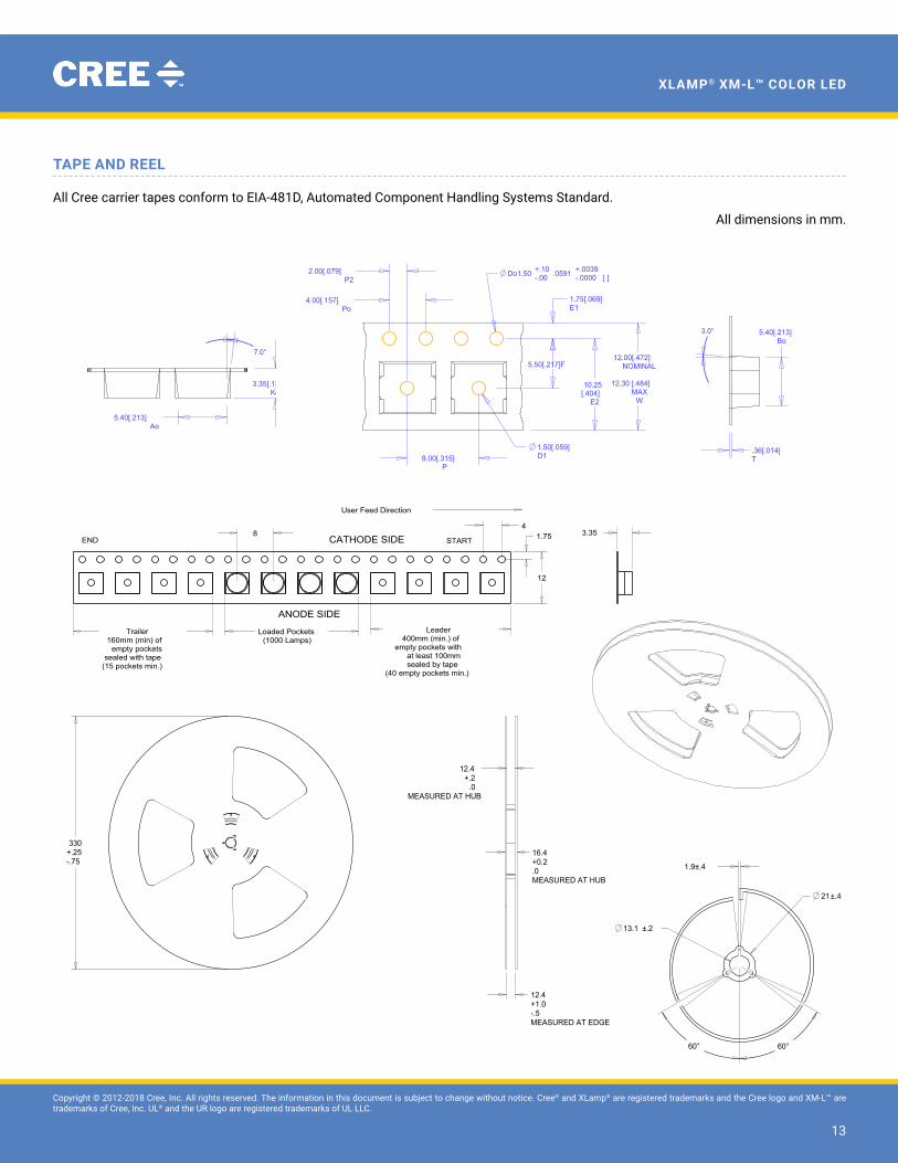
tAPE AnD rEEL
All Cree carrier tapes conform to eIA-481D, Automated Component Handling Systems Standard.
All dimensions in mm.
SIZE
TITLE
OF
REV.
SHEET
CDRAWING NO.
DATE
DATE
DATE
CHECK
FINAL PROTECTIVE FINISH
MATERIAL
APPROVED
DRAWN BY
THIRD ANGLE PROJECTION
X° ± .5 °.XXX ± .010.XX ± .03.X ± .06
FOR SHEET METAL PARTS ONLY
.XX ± .01
.XXX ± .005X° ± .5 °
UNLESS OTHERWISE SPECIFIEDDIMENSIONS ARE IN INCHES
AND AFTER FINISH.TOLERANCE UNLESS SPECIFIED:
SCALE
A
B
C
D
123456
6 5 4 3 2 1
A
B
C
D
Phone (919) 313-5300Fax (919) 313-5558
4600 Silicon DriveDurham, N.C 27703
UNAUTHORIZED PERSON WITHOUT THE WRITTEN CONSENTMAY NOT BE COPIED, REPRODUCED OR DISCLOSED TO ANYCONFIDENTIAL INFORMATION OF CREE, INC. THIS PLOTCONTANED WITHIN ARE THE PROPRIETARY ANDCREE CONFIDENTIAL. THIS PLOT AND THE INFORMATION
OF CREE INC.
NOTICE
SURFACE FINISH: 63
330+.25-.75
12.4+1.0-.5MEASURED AT EDGE
16.4+0.2.0MEASURED AT HUB
12.4+.2
.0MEASURED AT HUB
±.213.1
1.9±.4
±.421
60° 60°
1/10.500
A2400-00009
REEL, 13" X 12MM, 3 PIECE SNAP
-
ANTI-STATIC HIPS
----
----
09/29/09D. CRONIN
2400-00009INDEX QTY ITEM COMMENTS
1 1 2400-00009-CORE2 2 2400-00009-REEL
REVISONS
REV DESCRIPTION BY DATE APP'D
SIZE
TITLE
OF
REV.
SHEET
CDRAWING NO.
DATE
DATE
DATE
CHECK
FINAL PROTECTIVE FINISH
MATERIAL
APPROVED
DRAWN BY
THIRD ANGLE PROJECTION
SCALE
A
B
C
D
123456
6 5 4 3 2 1
A
B
C
D
Phone (919) 313-5300Fax (919) 313-5558
4600 Silicon DriveDurham, N.C 27703
UNAUTHORIZED PERSON WITHOUT THE WRITTEN CONSENTMAY NOT BE COPIED, REPRODUCED OR DISCLOSED TO ANY CONFIDENTIAL INFORMATION OF CREE, INC. THIS PLOT CONTAINED WITHIN ARE THE PROPRIETARY ANDCREE CONFIDENTIAL. THIS PLOT AND THE INFORMATION
OF CREE INC.
NOTICE
X° ± .5 °.XXX ± .25.XX ± .75.X ± 1.5
FOR SHEET METAL PARTS ONLY
.XX ± .25
.XXX ± .125X° ± .5 °
UNLESS OTHERWISE SPECIFIEDDIMENSIONS ARE IN
MILLIMETERS AND AFTER FINISH.TOLERANCE UNLESS SPECIFIED:
SURFACE FINISH: 1.6
Trailer160mm (min) of
empty pocketssealed with tape
(15 pockets min.)
Loaded Pockets(1000 Lamps)
Leader400mm (min.) of
empty pockets with at least 100mmsealed by tape
(40 empty pockets min.)
12
1.754
8 3.35
1/13.000
B2402-00012
XM LOADING SPEC
--
--
----
----
06/08/10D. CRONIN
REVISONS
REV DESCRIPTION BY DATE APP'D
A Loaded pocket count was 750 DDS 11/8/10 BS
B MADE CATHODE AND ANODE NOTE LARGER DC 2/26/12
END START
User Feed Direction
CATHODE SIDE
ANODE SIDE
12346 5
D
C
B
A
APP'DDATEBY
REVISIONS
REV DESCRIPTION
SIZE
TITLE
OF
REV.
SHEET
ADRAWING NO.
DATE
DATE
DATE
CHECK
FINAL PROTECTIVE FINISH
MATERIAL
APPROVED
DRAWN BY
THIRD ANGLE PROJECTION
SCALE
A
B
C
D
123456
4600 Silicon Drive
Fax (919) 313-5558
Durham, N.C 27703Phone (919) 313-5300
UNAUTHORIZED PERSON WITHOUT THE WRITTEN CONSENTMAY NOT BE COPIED, REPRODUCED OR DISCLOSED TO ANY CONFIDENTIAL INFORMATION OF CREE, INC. THIS PLOT CONTAINED WITHIN ARE THE PROPRIETARY ANDCREE CONFIDENTIAL. THIS PLOT AND THE INFORMATION
OF CREE INC.
NOTICE
X° ± .5 °.XXX ± .010.XX ± .03.X ± .06
FOR SHEET METAL PARTS ONLY
.XX ± .01
.XXX ± .005X° ± .5 °
UNLESS OTHERWISE SPECIFIEDDIMENSIONS ARE IN INCHES
AND AFTER FINISH.TOLERANCE UNLESS SPECIFIED:
SURFACE FINISH: 63 1/1DRAWING SCALE
A 2402-00011
XM 5050 CARRIER TAPE
4/23/10 D. CRONIN
CREE REFERENCE DRAWING FOR TEK-PAK DRAWING 018275
.36[.014]T
5.40[.213]Ao
3.35[.132]Ko
3.0° 5.40[.213]Bo
2.00[.079]P2
4.00[.157]Po
Do1.50 +.10-.00 .0591 +.0039
-.0000 [ ]
10.25[.404]
E2
7.0°
12.00[.472]NOMINAL
12.30 [.484]
MAXW
1.75[.069]E1
5.50[.217]F
1.50[.059] D18.00[.315]
P
POCKET SIZEAo - 5.40mm [.213"]Bo - 5.40mm [.213"]Ko - 3.35mm [.132"]
Copyright © 2012-2018 Cree, Inc. All rights reserved. The information in this document is subject to change without notice. Cree® and XLamp® are registered trademarks and the Cree logo and XM-L™ are trademarks of Cree, Inc. UL® and the UR logo are registered trademarks of UL LLC.
14
XLamp® Xm-L™ CoLor LED
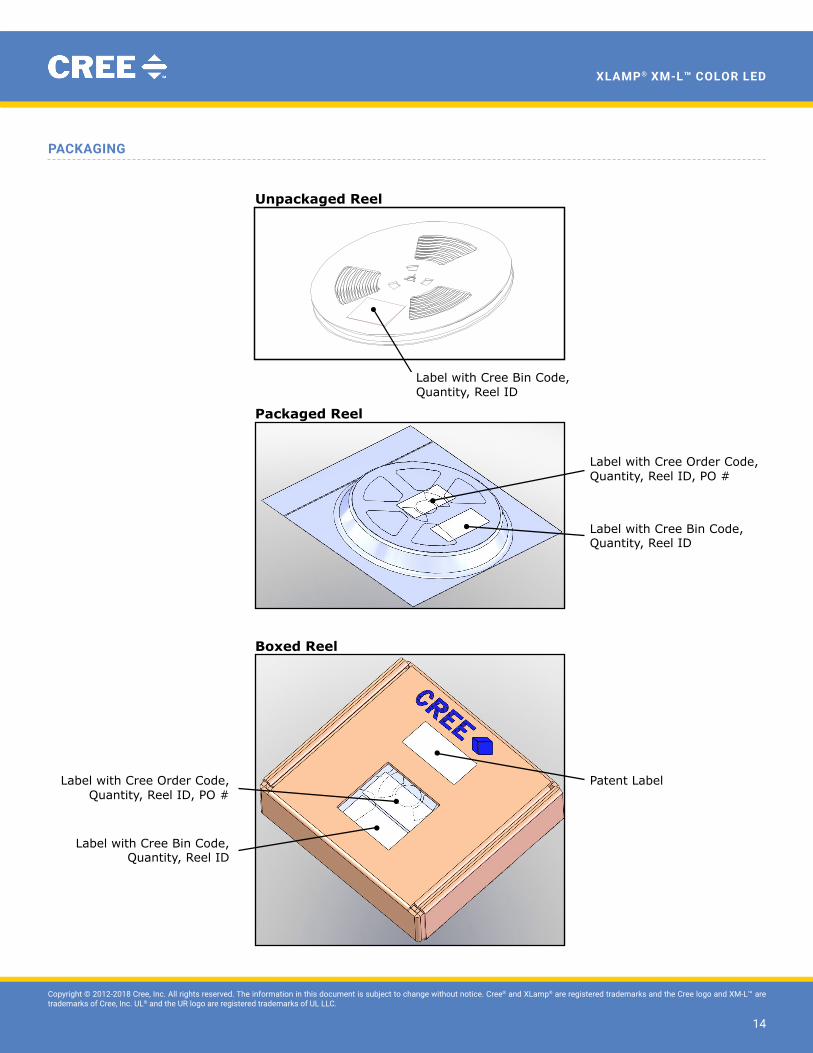
PACkAging
Label with Cree Bin Code, Qty, Lot #
Label with Cree Bin Code, Qty, Lot #
Vacuum-Sealed Moisture Barrier Bag
Dessicant (inside bag)
Humidity Indicator Card (inside bag)
Patent Label
Label with Customer Order Code, Qty, Reel ID, PO #
Patent Label
Label with Cree Bin Code, Quantity, Reel ID
Label with Cree Bin Code, Quantity, Reel ID
Label with Cree Order Code, Quantity, Reel ID, PO #
Label with Cree Order Code, Quantity, Reel ID, PO #
Label with Cree Bin Code, Quantity, Reel ID
Unpackaged Reel
Packaged Reel
Boxed Reel