crane incident handbook - warren forensics · crane incident handbook. ... common in mobile cranes...
TRANSCRIPT
Crane Incident Handbook
The Warren Group, Inc.R. John Phillips, P.E.

Table of Contents
IntroductionCrane Balancing ActRequirements and Standards Applicable to Most CranesLoad Chart AnalysisLoad Moment Indicator (LMI) SystemsTypical Crane IncidentsCrane Incident Site Initial StepsMeasure Lift RadiusBoom ConfigurationLoad DeterminationOther Site DocumentationOutriggers and Soil ConditionsCounterweightsEnvironmental ConditionsCrane Swing MechanismEquipment Integrity

Introduction
Cranes are powerful lifting devices that we see everyday in construction areas, shipping terminals, and industrial sites. They are so common that we often pass by them with little thought.
Cranes, however, can easily become involved in incidents that injure people or damage equipment. Cranes that are improperly sized for a job, improperly operated, or inadequately maintained will fall or drop their load despite their size and powerful appearance.
Computerized systems have been added to modern cranes that reduce the chance of operator error, but can increase the chance of overconfidence of operators and their supervisors, and also can be improperly operated themselves in a manner that can lead to accidents.
This handbook provides the basics of crane operation and safety requirements as well as guidelines for the initial investigation of crane incidents, including observations to be made at the site as well as questions to be asked during interviews of site personnel.
3

Crane Balancing Act
The operation of most cranes is a balancing act — one very similar to the childhood experience of using a playground seesaw. When the equipment isn’t properly balanced, the crane may succumb to the tipping force and fall to one side. Such a tipover is much more common in mobile cranes rather than gantry cranes or fixed-tower cranes that are secured to a building structure while it is being erected.
A Battle of ForcesIn many crane tipover incidents the weight of the lifted load and boom causes the crane to tip over in the direction of the load and boom. To overcome such a scenario, a crane employs a counterweight to offset the tipping force. However, if the counterweight is too heavy compared to the load and boom forces, the crane can tip over in the opposite direction toward the counterweight side. Cranes also have ground supports such as outriggers, wheels or a concrete foundation that must be able to resist the combined weights and tipping forces of the load, boom, counterweight, and crane superstructure.

A Balanced BoomThe tipping force applied through the crane boom depends on the load weight, boom length, and boom angle. The counterweight of most cranes is at a fixed distance from the crane point of balance and has limited capacity for adjustment for a specific load and boom angle. The crane ground support can provide increased resistance to tipping as its width and weight distribution increase beyond being a simple hinged seesaw point, but the effectiveness of the ground support can be limited by the area where the crane is located or must traverse. In many circumstances, a mobile crane equipped with full counterweights can tip over in the direction of the counterweights if the boom is raised to a high angle with an insufficient load applied to the boom.
Achieving Strength and StabilityCrane manufacturers must follow the American Society of Mechanical Engineers (ASME) B.30 series safety standards as required by the Code of Federal Regulations (CFR) regarding crane stability and strength. These standards require certain design and testing elements as well as the publication of crane load charts that are posted in sight of the operator. The crane load charts state the safe working loads for certain loads, boom angles, crane configurations, and counterweights.

This simple diagram shows the loads that contribute to the stability of a mobile truck crane

• Many modern cranes are equipped with computerized load moment indicators (LMI) that warn the operator as tipping forces are approached and even limit the crane movements that can cause a tipover. The LMI systems do not sense every tipping force applied to the crane such as inadequate ground support, the number of counterweights on the crane, and the boom and boom rigging configuration. These systems still must rely on the operator to properly position the crane and input the crane lifting conditions in order to prevent a tipover.
• With the equipment in proper alignment, the crane remains stable and upright, ready to move large, heavy loads. The crane — and people and industries that rely on it — can go about their tasks, safely and securely.

Common Crane Types
• Friction (Older, use systems of clutches and brakes driven by crane engine and gearbox, sometimes this type of crane is mandated by construction documents)
• Hydraulic (Most modern mobile cranes, motive and lifting functions powered by hydraulic pump(s) driven by crane engine, controls are electronic or hydraulic)
• Hybrid (Construction cranes that are driven by hydraulic power with pneumatic controls, often seen at roadway and bridge construction sites)
• Electric (Powered by either engine driven generator or festooned cables, often maintain constant electrical load by sending power to resistor banks or regenerative loading to power source)

ASME B30.5 Definitions For Mobile Cranes

10

Requirements and Standards Applicable to Most Cranes
• Code of Federal Regulations
• CFR 1910.180 (OSHA)
• CFR 1917.46 (Marine Terminals)
• ASME B.30 Standard Series
• SAE Standards
• Crane Manual!!!

Load Chart Analysis• Every crane is required to have a load chart specific to the crane in the operator’s cab as
well as the operator’s manual• In general, the load chart for a mobile crane will be split by a dark line showing the
maximum load for structural capacity above the line and the 85% tipping capacity below the line. Neither capacity should be exceeded because they allow for the added dynamic loads anticipated during a crane lift.
• The crane operator must know the lift weight as well as the radius before attempting a lift. With a standard load chart the lift weight must be determined by documentation or a reasonable estimate provided by the lift director, and the lift radius determined by a tape measure from the crane centerline or a boom angle indicator.
• The crane manual provides further definition to the crane load chart as to what adds to the total lift weight. This usually includes the boom configuration, the crane hook, and extensions stowed on the boom.
• Crane load charts often have different capacities based on outrigger and boom positions.• Rigging equipment must be included in the lift weight.• Side loading of the crane boom is not included in the load chart. Crane booms normally
have no designed capacity for side loading and side loading should not be attempted.

A typical load chart

Load Moment Indicator Systems (LMI)
• LMI systems are computerized equipment provided on most newer cranes to inform the operator of the load weight and radius, as well as any approaching overload conditions.
• LMI systems will shut down the lift as any overload conditions are approached and will force the operator to return to a safe crane loading.
• Most LMI systems do not sense all crane functions and require operator input as to boom length, any boom extensions, boom reeving, crane outrigger positions, etc. at crane startup. The newer systems require the operator to input this information at each crane startup.
• LMI systems depend on correct operator inputs prior to crane lifts.• LMI systems cannot detect or account for soil conditions, wind conditions, or other
environmental conditions. Those conditions remain the responsibility of the crane lift director.
• LMI systems usually have override keys that will allow continued crane operation beyond LMI limits. These overrides are sometimes needed to recover from lifts where the LMI locks out the crane functions due to overload, but are sometimes improperly used by crane operators to bypass the LMI. The override keys are sometimes prohibited to be in the possession of the crane operator or even at the job site.

A Grove PAT LMI (Load Moment Indicator)

A Grove SLI LMI System
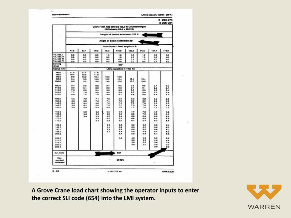
A Grove Crane load chart showing the operator inputs to enter the correct SLI code (654) into the LMI system.

Excessive lift radius for load capacity
Lack of proper taglines to control load
Inadequate ground support
Boom side loading, particularly in pile driving or removal
Inaccurate load estimate
Improper LMI system setup or operator override
Operator inattention
Inadequate counterweight
Improper load handling/rigging
Excessive winds
Improper operation of crane swing mechanism
Mechanical damage/equipment failure
Typical Crane Incidents

• How long before the equipment is moved? Is there time to photograph and measure the scene? If there is not enough time to measure the scene, paint marks or flags will help in further investigation.
• What was the intended lift? (load, lift, radius, boom configuration, outrigger position)
• What happened?
• Who witnessed the incident? Interview participants, many will be moved to other job sites or other employment a short time after the incident
• Who was the lift director?
• Request power up of LMI system, if in place, to determine settings. The crane batteries often lose power a few days after a tipover so this data could be lost.
Crane Incident Site Initial Steps

• Identify crane manufacturer, model number, serial number, load chart number
• Obtain or photograph the crane manual and load charts!!
• The crane manual and charts are required to be in the operator’s cab but are often confiscated by regulating authorities soon after an incident.
• The answer is (almost) always in the manual and charts.
• Manuals and charts are specific to individual cranes.If you don’t get them at the initial site inspection, you may never get them!
• If the crane manuals and load charts are not released, photograph the applicable parts of the manual and load charts
• Nomenclature specific to the crane is often contained in the manual and charts
Crane Incident Site Initial Steps, Continued

Identify Parties
Crane ownership
Bare rental or with operator
Lift director
Relationship among entities at site
Who maintains the crane
Operator’s employer
Operator’s experience/qualification
Rigger/ironworker’s employer
Load owner
Rigging equipment supplier
Load manufacturer’s lift instructions

A typical crane label identifying the manufacturer, model number, and serial number.

A certification label showing that a crane was recently inspected.

Measure Intended and Actual Lift Radius
• Both are based on the load radius from the crane centerline pivot pin
• The actual lift radius when a crane tipped or a boom collapsed can be difficult to determine because the load may swing away from the crane as it falls

A wall framing section that is being lifted beyond its intended lift radius and beyond the crane capacity after the wall section rotated because its orientation was not properly controlled by taglines to ground personnel.
Excessive Load Radius

The crane boom after it buckled due to overload because of excessive lift radius.

Boom Configuration and Attachments
• Inspect/measure/document
• Mounted attachments not in use can effect lift capacity
• Mounted attachments can include boom extensions that are not in use as well as boom transportation materials such as wood protective cribbing

A diagram from a crane manual showing the different boom configurations that can be used.

Load Determination
• Not just item being lifted
• Everything between boom and load
• Boom attachments

A crane hook block that must be considered as part of the total crane load. The hook block weight is stamped on a metal plate.
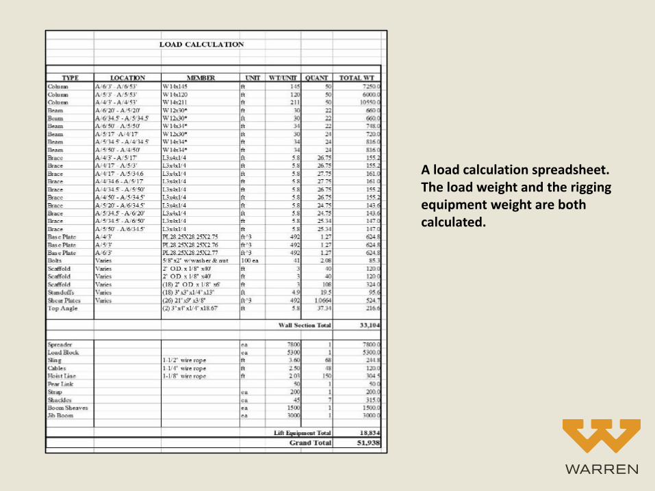
A load calculation spreadsheet. The load weight and the rigging equipment weight are both calculated.

Other Site Documentation
• Load final position
• Boom final position
• Tagline usage
• Rigging equipment
• Site landmarks
• Soil slope
• Equalizer position, wraps on boom drum

Outriggers and Soil Conditions
• Was the crane level?
• What was the outrigger use and position for mobile cranes?
• What crane mats and cribbing were used?
• What was the soil firmness?
• What soil impressions were left?
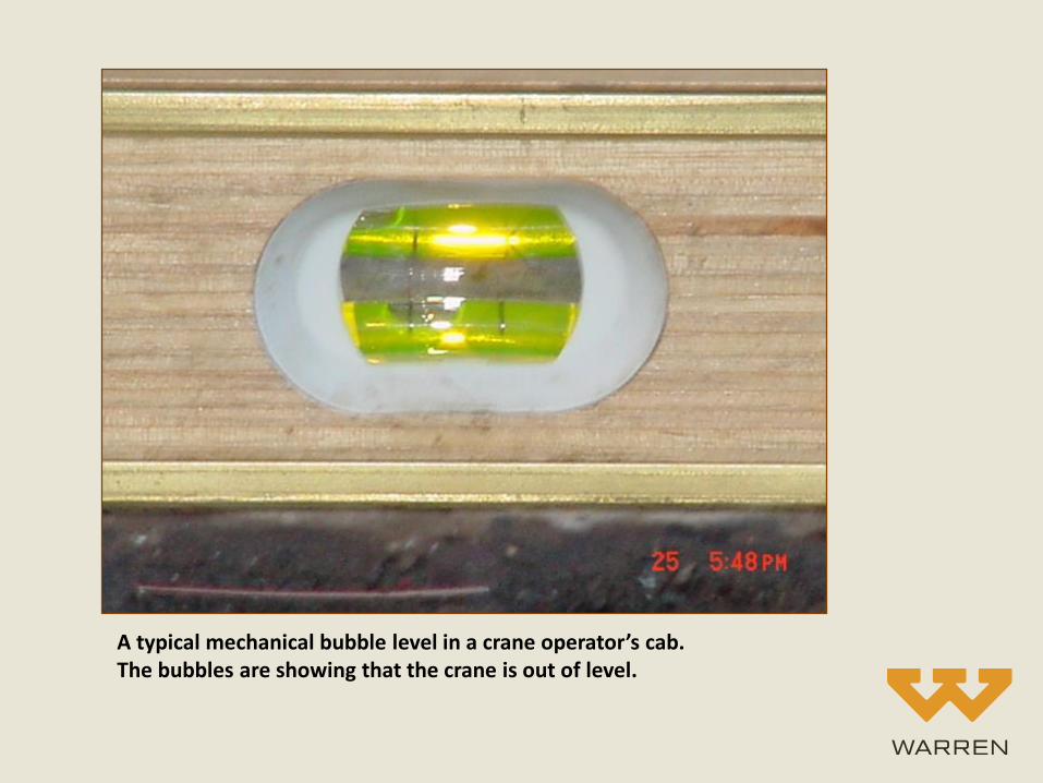
A typical mechanical bubble level in a crane operator’s cab. The bubbles are showing that the crane is out of level.

Outriggers and Soil Conditions
• Mobile cranes depend on stability through their outriggers. These are the four “legs” that are deployed onto soil or other working surfaces adjacent to the crane. When a mobile crane is set up at a site, the outriggers are deployed by a hydraulic mechanism that extends the four outriggers beyond the crane body and then jack the crane free of its wheels so that it is supported by the outriggers only.
• The ability of the crane to be supported to its rated loads is sometimes governed by the bearing capacity of the working surface to resist the loads applied by the crane outriggers. The outriggers are equipped with pads to distribute those loads, but the ability of the working surface under the pads to withstand those loads is often unknown.
• Detailed soil testing and evaluation is sometimes done to determine the ability of the working surface to withstand crane loads, however that is often impracticable at sites where the crane is used for only one lift or is moved frequently around a site. Instead, it is common to use a visual examination as well as crane mats to further distribute the outrigger loads. The mats provide a strong surface with a larger bearing area than provided by the outrigger pads on a crane. These mats have traditionally consisted of wood cribbing or wood pads made by the crane owner. More recently, companies have begun selling crane mats constructed of steel or other materials that are more portable and longer lasting than traditional mats.

Any investigation of a mobile crane turnover involves an evaluation of the working surface supporting the crane outriggers. This is not always an easy evaluation because the outriggers often dig in to the surface as the crane tips. It must be determined whether any damage to the working surface under the outriggers was the cause or result of the crane tipping.
A view of a wood crane mat that helps distribute the crane applied load. This wood mat appears simple but actually reduces the crane applied load to the working surface by about 400 percent when calculated in pounds per square foot.

Impressions showing good soil support of a crawler crane after an overload incident

Counterweights
• How many were in place? Counterweights are often removable for mobile crane transport to reduce highway loads. The removable counterweights generally require additional tractor trailers for transport in addition to an assist crane and additional crew members to install them.
• Superstructure and carbody counterweights. In addition to the readily visible superstructure counterweights there are often less visible carbody counterweights.
• Counterweight position. Some cranes have the ability to retract and extend counterweights as needed for transport and lifting operations.
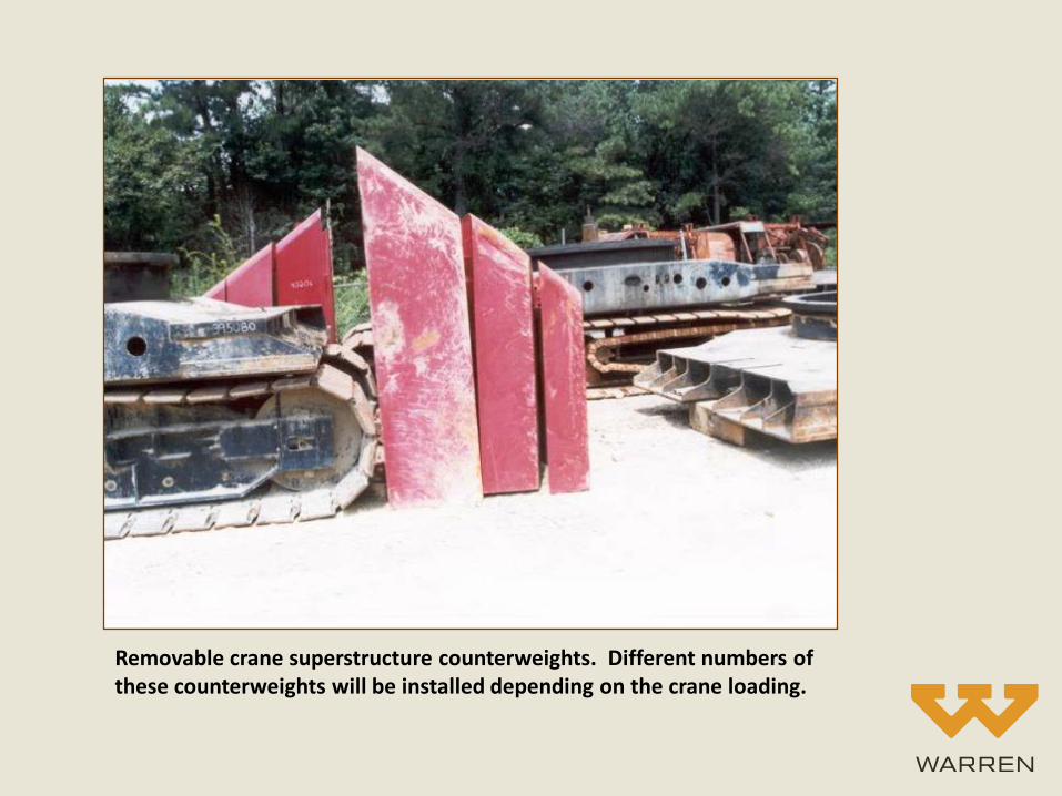
Removable crane superstructure counterweights. Different numbers of these counterweights will be installed depending on the crane loading.

A crane with an extendable counterweight. The operator left the counterweight in the retracted position while extending the boom at a low angle.
The crane tipped under the force of the boom alone because the counterweight was not positioned to resist the boom load. There was no load attached to the boom other than the hook block.

Environmental Conditions
• Wind effect on boom and load
• Rain effect on supporting soils
• Ground slope during a pick and carry operation
Crane Swing Mechanism
• Is it intact?
• Is the swing brake operable and in good condition?
• Was the swing lock (house lock) operable and engaged? The swing lock should always be engaged except when intentionally rotating the crane superstructure.

A rough terrain crane that swung unexpectedly while operating on a slope, damaging the crane boom.

The swing motor and the swing lock on the crane shown in the previous photograph. The swing brake is built into the cylindrical swing motor. The swing lock is to the right of the swing motor.

The swing brake controls of the crane previously shown.
The swing brake is set by the pedal on the left, which is self-locking similar to the parking brake of a car, and is released by the knob above the pedal.
The swing lock is separately operated.

Equipment Integrity
• Check boom, main, and auxiliary hoist integrities
• Check automatic and auxiliary brake condition and adjustment
• Check hoist clutch adjustments if applicable
• Check boom locking pawl operation. The locking pawl, if provided, must always be engaged except when intentionally changing the boom angle
• Check wire ropes for type of failure mechanisms
• Check rigging equipment for adequate design and condition
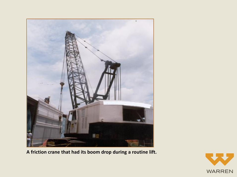
A friction crane that had its boom drop during a routine lift.

Brake adjustment measurement on the friction crane in the previous photograph.

Boom hoist drive clutch measurement on the same friction crane.

Boom hoist gearbox inspection.

A boom hoist auxiliary brake handle that had been made inoperable by the wire near the center of the photograph. The crane operator had installed the wire to lift the handle out of his way.

Prior Boom Damage
• Corroded fracture surfaces
• Overall corrosion
• Poor weld quality
• Mismatched repairs

Lattice boom parts after a boom collapse. It is normal to find multiple parts that separated during a boom collapse. All of the parts need to be inspected to see if any were defective in a manner that reduced the boom capacity.

Lattice boom fracture surfaces that were caused by a boom overload.
John Phillips, senior consulting engineer at Warren, has more than 30 years of crane and heavy equipment experience and more than 19 years of experience in forensic engineering. A licensed professional engineer in South Carolina, North Carolina, Georgia, Louisiana and Ohio, he’s NCEES registered both as a model engineer and with The United States Council for International Engineering Practice, USCIEP.
John has designed crane systems, supervised installation, tested and certified lifting equipment even serving as a project engineer for maintenance and certification of nuclear weapon lifting and handling systems.
For more information on this Crane Incident Handbook or if you have questions about the material contained in this publication, please contact John at [email protected].