craftsman dovetail jig l0807067
TRANSCRIPT
8/18/2019 Craftsman Dovetail Jig L0807067
http://slidepdf.com/reader/full/craftsman-dovetail-jig-l0807067 1/48
ModelNo,
171.25450
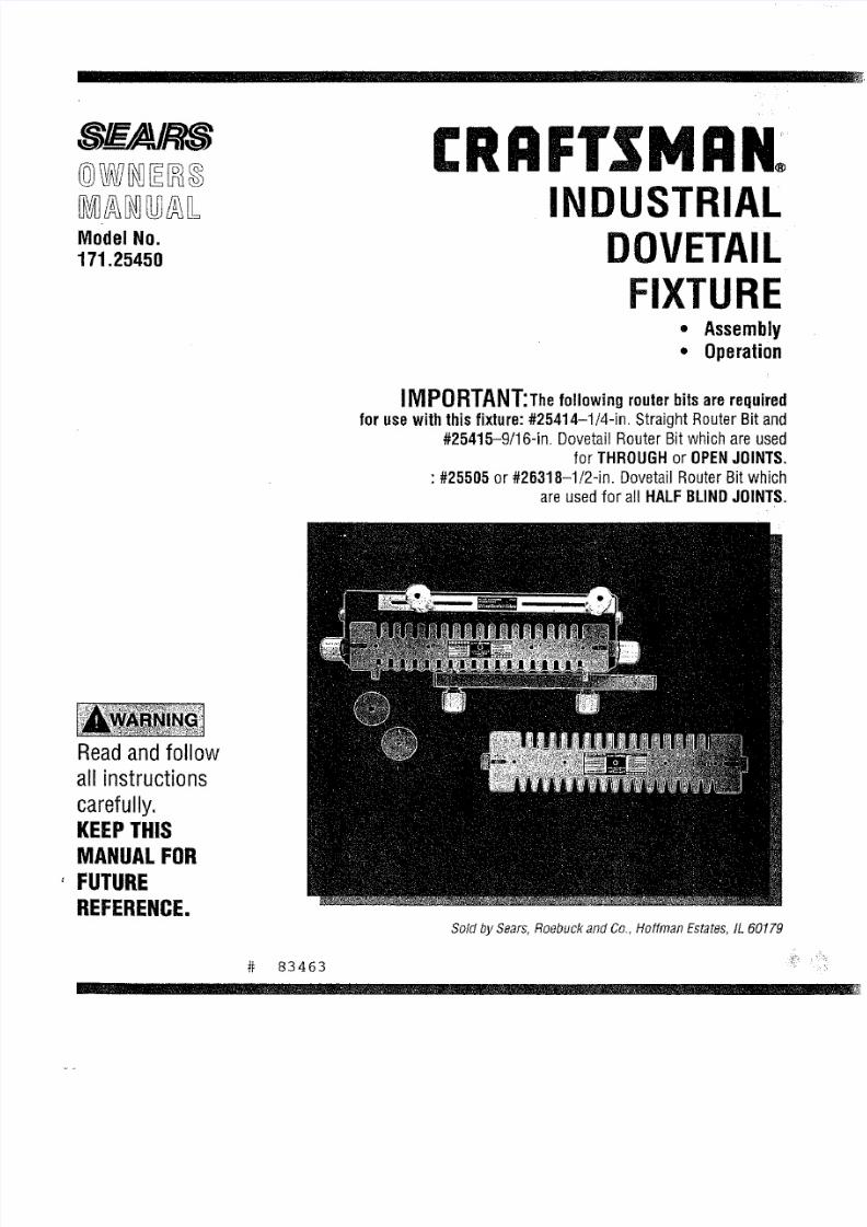
CRAFT$1VlAK
INDUSTRIAL
DOVETAIL
FIXTURE
• Assembly
• Operation
iMPORTANT;Thefollowingrouterbitsarerequired
for
usewith this fixture: 25414-1/4-in.
Straight Router Bit and
#25415-9/16-in. Dovetail Router Bit which are used
for
THROUGH
or OPEN
JOINTS.
: #25505 or #26318-1/2-in. DovetailRouterBit which
are usedfor a l HALFBLINDJOINTS.
Readandfollow
all instructions
carefully.
KEEPTHIS
MANUALFOR
'
FUTURE
REFERENCE,
Sold bySears,Roebuckand Co,,Hoffman Estates,IL 60179
83463

8/18/2019 Craftsman Dovetail Jig L0807067
http://slidepdf.com/reader/full/craftsman-dovetail-jig-l0807067 2/48
, i i
FAILURETOHEEDALLSAFETYAND
OPERATING
NSTRUCTIONS
ANDWARNINGSREGARDINGUSEOFTHISPRODUCTCANRESULT
IN SERIOUSBODILYINJURY
1)
KNOWYOURPOWERTOOL
Read
he
owner'smanualcarefully.Learn
its
applicationsand
Iimitatlonsaswell asthespecificpotentialhazardsarticularto
thistool.
2) GROUNDALLTOOLSUNLESSDOUBLENSULATED)
If tool is equippedwithanapproved3-conductorcordand a3-
pronggroundingtypeplug,it shouldbepluggedinto athreehole
electricalreceptaute.t adapters usedtoaccommodate two-
prongreceptacle,he adapterwire mustbeattachedo known
ground,(usuallythescrewsecuringreceptaclecoverplate).
Neverremovehird prong.Neverconnectgreengroundwireto a
terminal.
3) KEEPGUARDSNPLACE
--in workingorder,and
in
properadjustmentandalignment.
4) REMOVEADJUSTINGEYSANDWRENCHES
Forma habitof checkingo seethatkeysandadjustingwrenches
areremovedromtool beforeturningit on.
5) KEEPWORKAREACLEAN
Clutteredareasandbenchesnviteaccidents.Floormustnotbe
slipperydoeto waxor sawdust.
6} AVOIDDANGEROUSNVIRONMENT
Donot usepowertools
in
damporwet
locationsr
exposehornto
rain.Keepwork areawelI lighted.Provideadequatesurrounding
workspace.
7) KEEPCHILDRENWAY
All visitorsshooktbekeptata safedistancefromworkarea.
B) MAKEWORKSHOPHILD-PROOF
--with padlocks,masterswitches,or by removingstarterkeys.
9) DONOTFORCETOOL
It will dothejob betterandsaferattherateforwhichit was
designed.
10)
USEAPPROPRIATEOOL
Donotforcetool or attachmento doajob forwhich
it
wasnot
designed.
11)WEARAPPROPRIATEPPAREL
Donotwearlooseclothing,gloves,necktiesor jewelry(rings,
wristwatches)ogetcaughtin movingparts.Nonslipfootwearis
recommended.Wearprotectivehaircoveringo containlonghair.
Roll longsleevesel;Dyeheelbow.
12)
USESAFETYGOGGLESHeadProtection)
WearSafetyGogglesmustcomptywith ANSIZ87.1 at all times.
Also,usefaceordustmaskif cuttingoperations dusty,andear
protectors(plugsor muffs)duringextendedperiodsofoperation.
13)SECUREWORK
Useclampsora viseto holdworkwhenpractical,it's saferthan
usingyourhandandfreesbothhandsto operateool.
14)
DO
NOT
OVERREACH
Keep
proper
ootingandbalanceat all times.
15)MAINTAINOOLSWITHCARE
Keepools sharpandc]eanfor bestandsafestperformance.Follow
instructionsfor lubricatingandchangingaccessories.
16)
DISCONNECTOOLSBEFOREERVICING
-when changingaccessoriessuchas blades,bits,cutters,etc.
17)AVOIDACCIDENTALTARTING
Makesureswitch
is
in OFFpositionbefore
pluggingn.
18)USERECOMMENDEDCCESSORIES
Consulttheowner'smanualfor recommendedccessories.Follow
the instructionsthataccompanyheaccessories.Theuseof
improperaccessoriesmaycausehazards.
19)NEVER
STANDONTOOL
Serious
injury
couldoccur ;fthetool Istipped
or
thecuttingtool is
accidentallycontacted.0o notstorematerialsaboveor nearthe tool
thatwouldmakeit necessaryo standon thetoolto reachthem.
20)CHECKDAMAGEDARTS
Beforeurtheruseof thetooI,a guardor other
part
hatis damaged
shouldbecarefullycheckedto ensurethatit will operateproperly
andperformits
intended
unction.Checkforalignmentof racy(rig
parts,bindingof movingparts,breakageof parts,mounting,andany
otherconditionsthat mayaffectits operation.Aguardorotherpart
that
is
damagedshouldbeproperlyrepairedorreplaced.
21)DIRECTIONFFEED
Feedworkintoabladeor cutteronly againstthedirectionof rotation
of thebladeor cutter.
22)NEVERLEAVETOOLRUNNINGUNA'n'ENDED
Turnpoweroff.Do notleavetooluntilit comesto a completestop.
23)KEEPHANDSAWAYFROMCUT(1NGAREA
24)STORE
DLE
TOOLS
Whennot in use,toolsshouldbestoredindry,highor Iocked-up
place---outof reachofchildren.
25)O0
HOT
ABUSECORD
Keepcordawayfrom heat,oil, andsharpedges.
28)OUTDOORXTENSIONORDS
Whentoo
is
usedoutdoors,useonlyextensioncordssuitableor
useoutdoors,andso marked.
27)NEVER
USE
IN
ANEXPLOSIVETMOSPHERE
Normalsparkingof the motorcouldignitefumes,flarnmab;eiquids,
or combustibletems.
28)DRUGS,ALCOHOL,MEDICATION
Do notoperateool while underthe influenceof drags,alcohol,or
anymedication.
READ
ANDUNDERSTANDHISCOMPLETENSTRUCTIONBOOK
BEFOREUSINGTHISPRODUCT
2

8/18/2019 Craftsman Dovetail Jig L0807067
http://slidepdf.com/reader/full/craftsman-dovetail-jig-l0807067 3/48
ADDITIONALSAFETYNSTRUCTIONSORYOUR
INDUSTRIALDOVETAILFIXTURE
1) Alwaysweareyeprotectionhatcomplieswith currentANSI
StandardZ78A.
2) Noiselevelsvarywidely.Toavoidpossiblehearingdamage,wear
earpIugsor muffswhenusingtheDovetailFixtureor hoursata
time.
3) Wearadust maskalongwiththesafetygoggles.
4) Donot usethis DovetailFixturewith routerbitsor guide
bushingsotherthanthosespecifiedorthecuts beingmade.
5) FollowtheinstructionsinyourRouterOwnersManual.
6) Vibrationscausedbytherouterduringusecancauseasteners
to becomeoose.Beforeuseandperiodicallyduringusecheckall
fastenerso makesurethat theyareagtightandsecure.
7) Donot usethis productuntilall assemblynstallationstepshave
beencompleted,andyouhavereadandunderstandnit safetyand
operationalnstructionsn this manual,andtheRouterOwners
ManuaL
8) Makesurethattherouterbit is properlypositionedn therouter
so thatit doesnotcontacthe guidebushingorthetemplatewhen
cutting.
9) TheDovetailFixturemustbe securelymountedto aworkbench
or otherstablesurfacewhenin use.Thefrontof the baseshould
overhanghefrontof theworkbenchbynomerethan1/4" to provide
clearancewhenclampingworkpieceso theDovetailFixture.
10) DonotusetheDovetailFixtureas aworksurface.Doingsomay
causedamageo theDovetailFixture,whichcancauseit to beunsafe
to use.Aworkbenchshouldbeusedfor thispurpose.
11)Thisproductis designedocut
flat
workpieces.
Donotcutor
attemptocutworkpieceshat
are
notflat
or
thatareirregularly
shaped.
12)Thisproductis to beusedforcuttingwoodworkpiecesonly.
Do
not
usethisproductocutmetaloranyothernon-woadmaterial.
13)Thisproducthasbeendesignedo cutworkpieceshaving
thicknessesof 3/8"to 1".Donot useforworkpiecesof anyother
thicknesses.
14)Donotclampanyworkpieceso the DovetailFixtureor makeany
adjustmentso theDovetailFixtureunlessthe routerhasbeenurned
off, therouterbit is notturning,andtheRouterhasbeen
disconnectedromtheelectricaloutlet.
15)Whensetting"lhe-dopth-ot-cut"of the routerbit,makesurethat
theworkplaces clampedothe DovetailFixturen sucha.manner
that
therouterbitdoesnotcut
into the
Dovetailbasecausing
damageoit orpassibleseriousnjurytoyou.
16) ALWAYSNPLUGHEROUTERFROMTHE
ELECTRICALUTLETBEFORENSTALLINGRREMOVINGOUTER
BITSFROMTHEROUTERNDWHENADJUSTINGHECUTTING
DEPTHOFTHEROUTERBIT;ORWHENINSTALLINGRCHANGING
GUIDEBUSHINGS,
17)NEVERLiFTTHEROUTERUPWARDSWHENTHEROUTERS
"ON",THEROUTERIT
IS
ROTATING,NDTHEGUIDEBUSHINGS
NEARORTOUCHINGHETEMPLATE,ECAUSEHISWILLCAUSE
THEROUTERBITTOCUTINTOTHETEMPLATENDDAMAGET.
INTRODUCTION
o Your Sears/Craftsmanindustrial DovetailFixtureis an accessory used with your Routerto allow you to makedrawers, chests, and the like
where dovetail joints are used to join the front, back,and sides of the workpiece.
The Dovetail Fixturewig allow you to make1" spacedflush and flush offset and 318"rabbetedhaif-bfind dovetail joints, in addition you can
make1" spaced (or open) dovetail joints.
• Workplace widths up to 16"can beaccommodated.
Workplacethicknesses between318"and1" can beaccommodated,
The Dovetail Basehas six pockets moldedinto its front which are gaugesto aid you in setting the "depth-of-cut" for commonly used
depths: 3/8", 1/2", 5/8", 3/4'1,7/8", and 1".
The Dovetail Fixturecomes with two templates andtwo guide bushings for making bait-blind and through or openjoints.
Sears/Craftsman router bits,#25414 and#25415, WHICH MUSTBE PURCHASEDSEPARATELY,are requiredto makethe THROUGHor
OPENjoints.
Sears/Craftsman router bit, #25505 or #26318, WHICH MUST BE PURCHASEDSEPARATELY,s required for making the haIf-bIind joints.
• Eachtemplate has a label, describingthe joint that can becut, along with set up information, the bit and guide bushing required, and the
stop block setting for a particular joint.
The Dovetail Fixture can be used with al Sears/Craftsman Routers.
With a separately purchasedSears/Craftsman#25326, UniversalRouter Adapter,the DovetagFixture can be usedwith many non-
Craftsman Routers, such as, Black & Decker,Makita, and SkiL
UNPACKINGNDCHECKINGCONTENTS
in order to simplify handIing and to minimizeany damagethat may occur during shipping, your Industrial Dovetail Fixtureis packaged
unassembled,
Separate all parts from the packing materials and check eachonewith the igustrations and list of parts at the endof this manuaIto make
sure that ag partsare present beforediscarding any packagingmaterial.
• If any parts are missing or cannot beaccounted for, do not attempt to assemble,install, or usethe industrial DovetailFixture
until the missing parts havebeenobtainedand the product has beenassembled correctly.
Contact your localSearsRetail Outletfor a repIacement product or for the missing parts.
3
8/18/2019 Craftsman Dovetail Jig L0807067
http://slidepdf.com/reader/full/craftsman-dovetail-jig-l0807067 4/48
ASSEMBLYNSTRUCTIONS
Thefollowingoolsare requiredorassembly:
1)
Amediumsized
Phillips
crewdriver,
2) Asmallor mediumsizedadjustablewrench.
ASSEMBLYOFTHERIGHTSIDETEMPLATESUPPORTTOTHEDOVETAILBASE
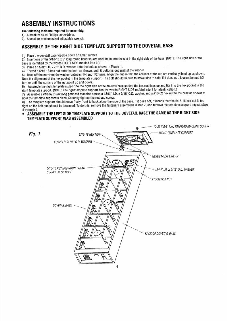
1). Placehe dovetailbaseopsidedownona flat surface.
2) insertoneof the5/16-18x 2" longroundheadsquareneckboltsinto thes ot inthe right
side
of thebase.(NOTE:Therightsideof the
bases identifiedbythewordsRIGHTSIDEmoldedintoit.)
3) Placea11/32"I.D_x 7/8"O.D.washerontotheboltasshownin Figure1,
4) Threada5/16-18hexnutontothe bolt,asshown,until it bottomsout againsthe washer,
5) Backoffthe nutfromthe washerbetween1/4and1/2turns.Nigh thenutsothatthecornersof thenutareverticallYineduPasshown.
Notethe alignmentof the hexpocket
in
thetemplatesupport.Theboltshouldbefreeto movesidetoside;if it doesnot, loosenthenut1/3
turn or untilthecornersof thenutpointupanddown.
8) Assembleherighttemplatesupportto therightsideof thedovetailbaseso thatthe hexoutlinesupandf ts into thehexpocketinthe
right templatesupport,(NOTE:Therighttemplatesupport
has
thewords RIGHTSIDEmoldedinto it for identification.)
7) Assemblea #10-32x 5/8°ongpanheadmachinescrew,a 13/64" .D.x 9/16"O.D.washer,anda#10"32hexnutt° thebaseassh°wn t°
holdthetemplatesupportin place.Securelyightenthe nut andscrew_
8)
The
templatesupportshouldmovefreelyfrontto backalongthe sideof thebase,If it doesnot,it meanshatthe 5/16-18hexnut is too
tight onthebolt andshould
be
loosened.Todo this, removethefastenersassemblednstepT,andremovethetemplatesupport;repeatsteps
4 through7.
•
ASSEMBLETHE LEFT SIDE TEMPLATESUPPORT TOTHE DOVETAIL BASETHE SAMEAS THE RIGHT SIDE
TEMPLATE SUPPORT WAS ASSEMBLED
Fig. 1
"/8"ongPANHEADACHINECREW
11/32"LO.XT/8"O.D.WASHER
MUSTLINEUP
5/16-18X2"ongROUNDEAD
SQUAREECKBOLT
?HEXNUT
_.D.WASHER
DOVETAILASE
_ BACKOFDOVETAILASE
8/18/2019 Craftsman Dovetail Jig L0807067
http://slidepdf.com/reader/full/craftsman-dovetail-jig-l0807067 5/48
ASSEMBLYOFTHETOPCLAMPINGBARTOTHEDOVETAILBASE
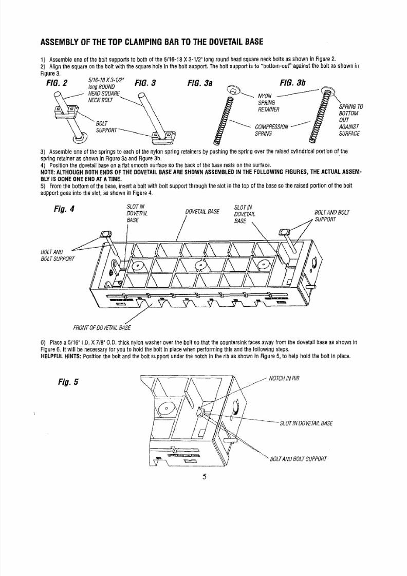
1)
Assemble
neof theboltsupportsto bothofthe 5/16-18
X3-1/2 long
round
head
squareneckboltsas shown
inFigure2.
2) Alignthe
square
onthebolt
with
the squareholein the boltsupport.Theboltsupport
is
to =bottom-out"againstthe boltasshown
in
Figure3.
FIG.2 5/16-18X3-1/2"IG.3
longROUND
HEADSQUARE _-x
,o,,
FIG. 3a
3) Assembleoneofthespringsto eachof thenylonspring retainersby pushingthespringovertheraisedcylindricalportionof the
springretaineras shownin Figure3aandFigure3b,
4) Positionthedovetailbaseonafiat smoothsurfaceso the backofthe baserestsonthesurface.
NOTE:ALTHOUGHOTHENDSOFTHEDOVETAILASEARESHOWNASSEMBLEDNTHEFOLLOWINGIGURES,THEACTUALASSEM-
BLYSDONEONEENDATATIME.
5) Fromthe bottomofthe base,inserta boltwithbolt supportthroughtheslotin thetopof thebasesothe raisedportionof thebolt
supportgoesinto theslot,asshownin Figure4,
Fig, 4 SLOTN SLOTN
DOVETAIL DOVETAILASE DOVETAIL BOLTANDOLT
EASE / BASE
BOLTAND
BOLTSUPPORT
FRONTOFDOVETAILASE
6) Placea5/16" I.D.X 7/8"O.D.thick nylonwasheroverthe boltso that thecountersinkacesawayfromthedovetailbaseas shownin
Figure6. It will benecessaryor youto holdthebolt in placewhenperforminghis andthe followingsteps.
HELPFULHINTS:Positionhe bolt andtheboltsupportunderthenotchin theribas shownin Figure5, to helpholdthebolt in place,
Fig. 5 _ NOTCHNRIB
SLOTINDOVETAILASE
BOLTANDOLTSUPPORT
8/18/2019 Craftsman Dovetail Jig L0807067
http://slidepdf.com/reader/full/craftsman-dovetail-jig-l0807067 6/48
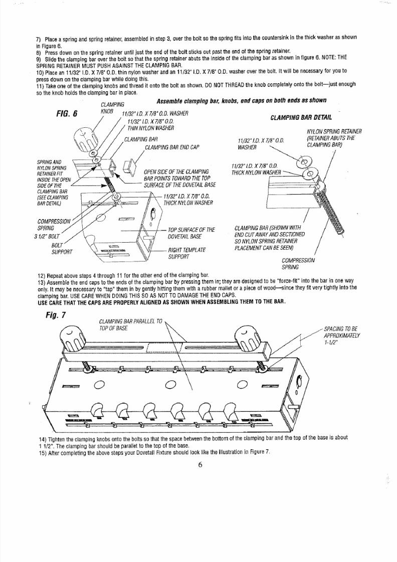
7)
Placeaspringandspringretainer,assembled
n
step3, overthebolt so
the
springfits
into
the
countersink
n
the
thick
washer
asshown
In Figure6.
8) Pressdownonthespringretaineruntiljust the
end
of theboltsticksoutpasttheendofthe springretainer.
9) Slidethe clampingbaroverthe boltsothatthespringetainerabutstheinsideof theclampingbarasshownin figure6. NOTE:THE
SPRING
RETAINER
MUST
PUSHAGAINSTTHECLAMPNGBAR.
10)Placean11/32"I.D.X 7/8"
O.D.
thin nylon
washer
andan 11/3Z I.D.X7/8"O.D.washerover thebolt.It will benecessaryor youto
pressdownonthe dampingbar whiledoingthis.
11) Takeone
of
the
clamping
nobsandthread
it
ontotheboltasshown.DONOT
THREAD
he knobcompletelyontothe bolt--just
enough
so
theknob
holds
he clampingbarin place.
SPRINGND
NYLONSPRING
RETAINERIT
INSIDEHEOPEN
SIDEOFTHE
CLAMPINGAR
(SEECLAMPING
BARDETAIL)
\
CLAMPING
Assembleclampingbar,knobs,endcapson bothends asshown
t f/32"LD.X 7/B"O.D.WASHER
11/32"LD.X T/8"O.D.
THINNYLONWASHER
SPRING
31/2 BOLT
BOLl
SUPPORT
FIG. 6
KNOB
CLAMPINGAR
CLAMPINGARENDCAP
OPENIDEOFTHECLAMPING
BARPOINTSOWARDHETOP
SURFACEFTHEDOVETAILASE
11/32"LD.X 7/8"O,D.
t THICKNYLONASHER
/ TOPSURFACEFTHE
DOVETAILASE
-- RIGHTTEMPLATE
SUPPORT
CLAMPINGBARDETAIL
NYLONSPRINGETAINER
11/32"LD.X7/8"O.D. (RETAINERBUTSTHE
WASHER LAMPING SAR)
/
CLAMPING
AR
(SHOWNWITH
/
ENDCUTAWAYANDSECT ONED /
SONYLONSPRINGETAINER /
PLACEMENTANBESEEN) /
COMPRESSION
SPRING
12)Repeatabovesteps4 through11for theotherendof the clampingbar.
13)Assembleheendcapstothe endsof theclampingbarby pressinghemin; theyaredesignedo be"force-fit"intothe barin oneway
only.It maybenecessaryo "tap"themin by gentlyhittingthemwitha rubbermatletora pieceof wood--sincetheyfit verytightly intothe
clampingar,SECARE WHEN DOINGTHISSOAS NOT
TO
DAMAGETHEEND
CAPS,
USECARETHATTHECAPSAREPROPERLYALIGNEDASSHOWN WHEN ASSEMBLINGTHEM TO THEBAR.
fig.
CLAMPINGARPARALLELO
TOPOFBASE
J SPACINGOBE
APPROXIMATELY
1-1/2"
0 0 0
14)Tightenheclampingknobsontotheboltssothatthespacebetweenhebottomof theclampingbarandthetop of thebaseis about
1 1/2".Theciampingbarshouldbeparalletothe topof thebase.
15)Aftercompletinghe abovestepsyourDovetailFixtureshouldlooklikethe illustrationn Figure7.
6
8/18/2019 Craftsman Dovetail Jig L0807067
http://slidepdf.com/reader/full/craftsman-dovetail-jig-l0807067 7/48
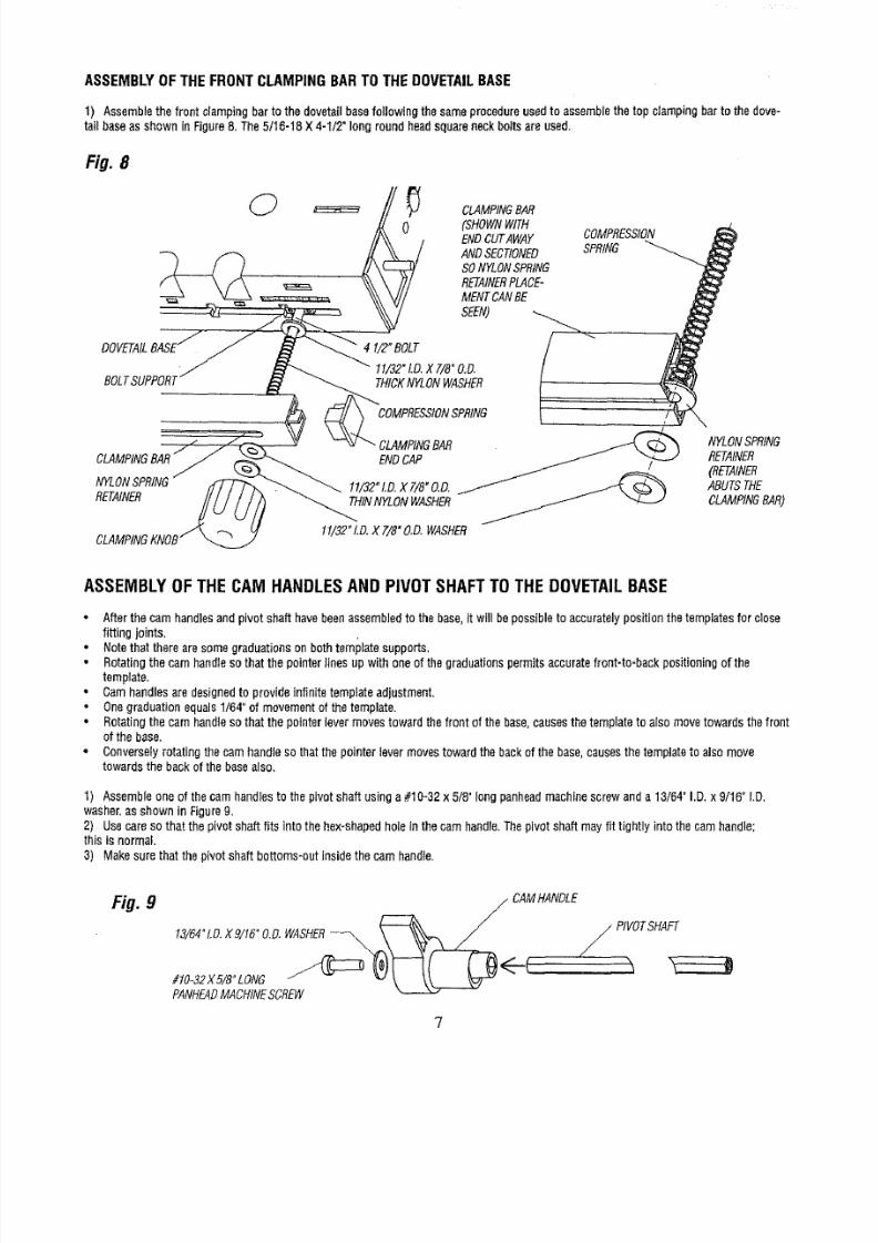
ASSEMBLYOFTHEFRONTCLAMPINGBARTOTHEDOVETAILBASE
1) Assemblehe front clampingbarto thedovetailbasefollowingthesameprocedureusedto assemblehetop clampingbar tothedove-
tail baseas shownin Figure8. The5/16-18X4-1/2"longroundheadsquareneckboltsareused,
Fig. 8
BOLT
0
4 I/2" BOLT / ""
11/32"1.D.7/8"O.D,
THICKNYLONWASHER
COMPRESSIONPRING
CLAMPINGAR
ENDCAP
1 /32"LD.X7/B"O.D,
RETAINER THINNYLONWASHER
CLAMPINGAR
(SHOWNWITH
ENDCUTAWAY
ANDSECTIONED
SONYLONPRING
RETAINERLACE-
MENTCANBE
SEEN)
COMPRESSION
SPRING
NYLONSPRING
RETAINER
(RETAINER
ABUTSTHE
CLAMPINGAR)
11/32".D.X 7/8"O.D.WASHER
ASSEMBLYOFTHECAMHANDLESANDPIVOTSHAFTTOTHEDOVETAILBASE
Afterthecamhandlesandpivotshafthavebeenassembledo thebase,it will be
possible
o accuratelypositionthetemplatesor close
fitting
joints,
Notethat therearesomegraduationsonbothtemplatesupports.
• Rotatinghecamhandlesothat the
pointer
inesup withone of thegraduationspermitsaccurateront-to-backpositioningof the
template.
• Camhandlesaredesignedo provideinfinitetemplateadjustment.
Onegraduationequals1/64"of movementof thetemplate.
• Rotatinghecamhandlesothat thepointer
lever
movestowardthefrontof thebase.causesthetemplateto alsomovetowardsthefront
of thebase.
• Converselyotatingthecamhandlesothat thepointerlevermovestowardthebackof the base,causesthetemplateto alsomove
towardsthebackof thebasealso.
1) Assembleoneof thecamhandlesto thepivotshaftusinga #10-32x 5/8 longpanheadmachinescrewanda 13/64"I.D.x9/16"LD.
washer,asshowninFigure9,
2) Usecaresothatthe pivotshaftfits
into
thehex-shapedholein thecamhandle.Thepivotshaftmayfit tightly intothecamhandle;
this isnormal.
3) Makesurethatthepivotshaftbottoms*outnsidethecamhandle.
Fig. 9
/ CAMHANDLE
13/64".D.X9/16°0.O,WASHER-_,,,,_ _ PIVOTSHAFT
7
8/18/2019 Craftsman Dovetail Jig L0807067
http://slidepdf.com/reader/full/craftsman-dovetail-jig-l0807067 8/48
8/18/2019 Craftsman Dovetail Jig L0807067
http://slidepdf.com/reader/full/craftsman-dovetail-jig-l0807067 9/48
8/18/2019 Craftsman Dovetail Jig L0807067
http://slidepdf.com/reader/full/craftsman-dovetail-jig-l0807067 10/48
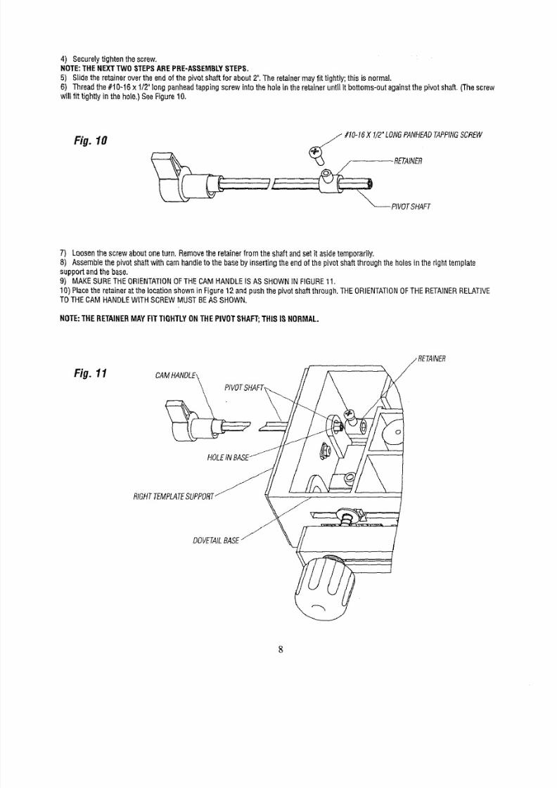
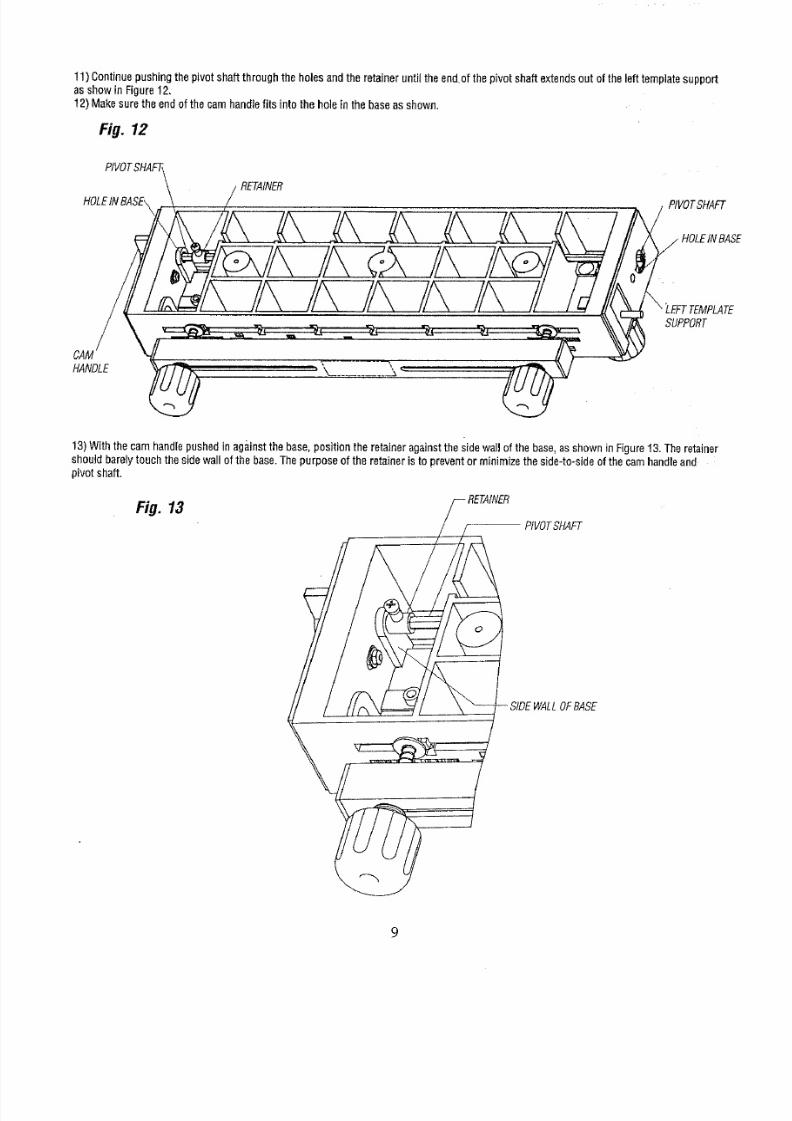
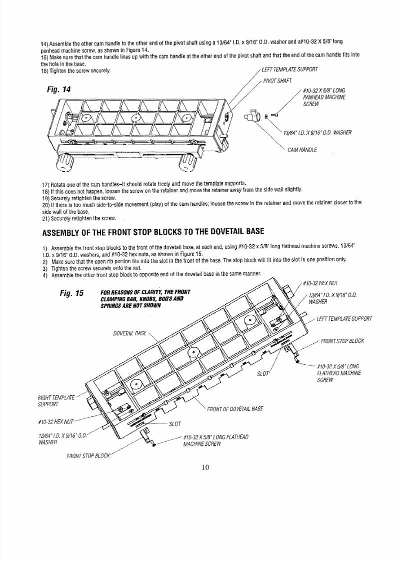
14)Assemblehe othercamhandleo theotherendof thepivotshaftusinga 13/64"I,D.x 9/16"O.D,washeranda#10-32X 5/8"long
penheadmachinescrew,asshownin Figure14.
15)Makesurethat thecamhandlelinesupwiththecamhandleat theotherendofthe pivotshaftandthat theendofthe camhandlefitsinto
theholein thebase.
16)Tightenthe screwsecurely, LEFTTEMPLATEUPPORT
Fig. 14
/_ #10-32X5/8"LONG
PANHEADACHINE
SCREW
_" DAMHANDLE
17)Rotateoneof thecamhandtes-ltshoutdrotatefreelyand movethetemplatesupports,
18)If this doesnot happen,oosenthescrewon the retainerandmovetheretainerawayfrom thesidewall slightly,
19)Securelyretightenthescrew.
20)If thereis toomuchside-to-sidemovement(play)of thecamhandles;oosenthescrewin theretainerandmovetheretainerc/oserto the
sidewaltof thebase.
21)Securelyretightenthescrew,
ASSEMBLYOFTHEFRONTSTOPBLOCKSTOTHEDOVETAILBASE
1) Aseemblehefrontstopblocksothefront of thedovetailbase,at eachend,using#10-32x 5/8 long flatheadmachinescrews,13/64_
I.D.x 9/16"O.D.washers,and# 0-32 hexnuts,as shownin Figure15.
2) Makesurethattheopenrib portionfits intothe slotin thefrontof thebase.Thestopblockwglfit intothe slotin onepositiononly,
3) Tightenhescrewsecurelyontothenut.
4) Assembleheotherfrontstopblockto oppositeendo1thedovetagbaseinthesamemanner.
Fig. 15
FORREASONSFCLARITY,THEFRONT
CLAMPINGAR,KNOBS,BOLTSND
SPRINGSRENOTSHOWN
WASHER
DOVETAILASE
SLOT
#10_32XB/8OLONG
FLATHEADMACHINE
SCREW
SUPPORT
#10-32HEX
13/64LD.X9/16°O.D/
WASHER J
FRONTTOPBLOCI_
_ FRONTOFDOVETAtLASE
5/8"LONGFLATHEAD
MACHINESCREW
10
8/18/2019 Craftsman Dovetail Jig L0807067
http://slidepdf.com/reader/full/craftsman-dovetail-jig-l0807067 11/48
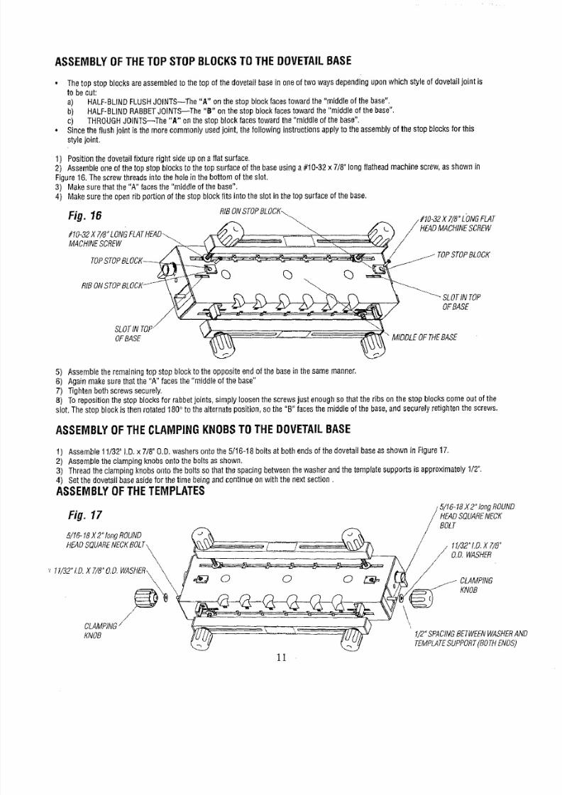
ASSEMBLYOFTHETOPSTOPBLOCKSTOTHEDOVETAILBASE
•
Thetopstopblocksareassembledothetop of thedovetailbasein oneoftwowaysdependinguponwhichstyleofdovetailjointis
to becut:
a) HALF-BLINDLUSHJOINTS--TheA" onthestopblockfacestowardthe"middleof thebase".
b) HALF-BUNDRABBETOINTS_The B onthestopblockfacestowardthe"middleof thebase".
c) THROUGHOINTS--The"A" onthestopblockfacestowardthe"middleof thebase".
• Sincetheflushjoint is themorecommonlyusedjoint,thefollowinginstructionsapplyto theassemblyof thestopblocksfor this
stylejoint.
1) Positionthedovetailfixturerightsideupon aflat surface.
2) Assembleoneof thetop stopblocksto thetop surfaceof thebaseusinga#10-32x 7/8"longflatheadmachinescrew,as shownin
Figure16.Thescrewthreadsintotheholeinthe bottomofthesIot.
3) Makesurethatthe "A" facesthe "middleof thebase".
4) Makesuretheopenribportionof thestopblockfits intotheslot in thetop surfaceof thebase.
Fig.
16
RfBONSTOPLOCK_
#10_32X 7/8_LONG \
MACHINECREW
#t0-32X7/8"L'ONGLAT
HEADMACHINECREW
TOPSTOPBLOCK
SLOTNTOP
OFBASE
SLOTIN TOP
OFBASE
MIDDLEOFTHEBASE
5) Assembleheremainingtopstopblockto theoppositeendof thebaseinthesamemanner.
6) Againmakesurethatthe "A" facesthe"middleof thebase"
7) Tightenbothscrewssecurely.
8) Torepositionthestopblocksfor rabbetoints,simplyloosenthescrewsjustenoughso thattheribson the stopblockscomeout of the
slot,Thestopblockisthenrotated180°to thealternateposition,sothe
B
facesthe middleofthebase,andsecurelyretightenhe screws.
ASSEMBLYOFTHECLAMPINGKNOBSTOTHEDOVETAILBASE
1) Assemb_e1_/32D.x 7/8"____was_ers_ntot_e_/1_-18b_itsat b_thends_f t_ed__etai_aseassh__n in Figure17_
2) AssembleheclampingknobsontotheboItsasshown.
3) Threadtheclampingknobsontothe boltsso that thespacingbetweenhewasherandthetemplatesupportsis approximately1/2".
4) Setthedovetailbaseasidefor thetimebeingandcontinueon withthe nextsection.
ASSEMBLYOFTHETEMPLATES
/ 5/16-18X2" longROUND
Fig. 17 / HEADQUARENEC
BOLT
5/t6- t8 X2°tongROUND
HEADSQUAREECKBOLT\
\
11/32".D.XT/8"
// O.D,WASHER
KNOB
CLAMPING
KNOB
11
/2"SPACINGETWEFNASHERND
TEMPLATEUPPORTBOTHENOS)
8/18/2019 Craftsman Dovetail Jig L0807067
http://slidepdf.com/reader/full/craftsman-dovetail-jig-l0807067 12/48
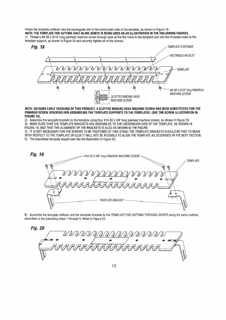
•Placethetemplatestiffenerinto therectangularslotin theunderneathideof thetemplate,asshowninFigure18.
NOTE:THETEMPLATEORCUTTINGALF-BLINDOINTSSBEINGUSEDASANILLUSTRATIONNTHEFOLLOWIHGIGURES.
1) Threada #8-36x 3/16"longpanheadmachinescrewthrougheachof the fiveholesin thetemplateandinto thethreadedholesin the
templatesupport,asshowninFigure24andsecurelyightenallof thescrews.
Fig.
18 _ TEMPLATETIFFENER
\ _ _ _ J jRECTANGULARSLOT
TEMPLATE
_ _ MACHINESCREwSLOTTEDINDINGEAD_ _ MA#&3gX3 6"t°ngPANHEADCREW
NOTE:ONSOMEEARLYERSIONSOFTHIS
PRODUCT,
SLOTTEDINDINGHEADMACHINESCREWHASBEENSUBSTITUTEDORTHE
PANHEADCREWSPECIFIEDORASSEMBLINGHETEMPLATEUPPORTSOTHETEMPLATES.SEETHESCREWLLUSTRATIONN
FIGURE18),
2) Assemblehetemplatebracketso thetemplateusingfour #10-32x 3/8°longpanheadmachinescrews_as shownin Figure19.
3) MAKESURETHATTHETEMPLATEBRACKETSREASSEMBLEDOTHEUNDERNEATHIDEOFTHETEMPLATE,SSHOWNN
FIGURE19,ANDTHATTHEAL]GNMENTOFTHEBRACKETSS ALSOASSHOWNNTHEFIGURE.
4) IT IS NOTNECESSARYORTHESCREWSOBETIGHTENEDTTHISSTAGE;HETEMPLATERACKETSHOULDBEFREETOMOVE
WITHRESPECTOTHETEMPLATERELSETWILLNOTBEPOSSIBLEOALIGNTHETEMPLATESDESCRIBEDNTHENEXTSECTION.
5) Theassembledemplateshouldlookliketheillustrationin Figure20.
Fig. 19
#10-32X3/8"tongPANHEADACHINECREW
TEMPLATE
'\
_- TEMPLATERACKET...
6) Assemblehetemplatestiffenerandthetemplatebracketso the TEMPLATEORCUTTINGHROUGHOINTSusingthesamemethod
describednthe precedingsteps1through5, Refero Figure20.
Fig. 20
lg
8/18/2019 Craftsman Dovetail Jig L0807067
http://slidepdf.com/reader/full/craftsman-dovetail-jig-l0807067 13/48
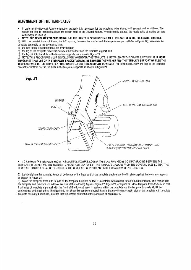
ALIGNMENTOFTHETEMPLATES
Inorderfor theDovetailFixtureto functionproperly,it is necessaryor thetemplateso bealignedwithrespectto dovetailbase.The
reasonfor this, isthatdovetailcutsareatboth endsof theDovetailFixture.Whenproperlyaligned,he resultbeingall matingcorners
willalwaysbelinedup.
NOTE:THETEMPLATEORCUTTINGHALF-BLINDOINTSSBEINGUSEDASANILLUSTRATIONNTHEFOLLOWINGIGURES,
1) Withthe dovetailbasesti l havingthe 1/2"spacingbetweenhewasherandthetemplatesupports(Referto Figure17),assemblehe
templateassemblyo thedovetailsothat:
a) theslotin thetemplatebracketfits overthebolt,
b) thelegof the templatebrackets betweenhewasherandthetemplatesupport,and
c) thelegsfit intotheslotsinthetemplatesupports,asshownin Figure21.
d) NOTE:THISPROCEDUREUSTBEFOLLOWEDWHENEVERHETEMPLATESINSTALLEDONTHEDOVETAILIXTURE.TISMOST
IMPORTANTHATLEGOFTHETEMPLATERACKETLWAYSEBETWEENHEWASHERNDTHETEMPLATEUPPORTORELSETHE
TEMPLATEWILLNOTBEPROPERLYOSITIONEDORCUTTINGACCURATEOVETAILS.orinitialsetup,Allowthelegsofthe template
bracketto "bottomout" inthe slotsinthe tempiatesupportsasshownin Figure21.
Fig. 21
WASHER
BOLT_
TEMPLATERACKET
SLOTN THETEMPLATERACKET
_ RtGHTTEMPLATEUPPORT
j SLOTINTHETEMPLATESUPPORT
0
"_TEMPLATERACKETBOTTOMS-OUT"AGAINSTHIS
SURFACEBOTHNDSOFDOVETAILASE)
TOREMOVEHETEMPLATEROMTHEDOVETAILIXTURE,LOOSENHECLAMPINGKNOBSSOTHATSPACINGETWEENHE
TEMPLATEBRACKETNDTHEWASHERSABOUT1/2";GENTLYLiFTTHETEMPLATEPWARDFROMTHEDOVETAILASESOTHATTHE
TEMPLATERACKETCLEARSHESLOTSINTHETEMPLATESUPPORTNDSTORENACONVENIENTOCATION,
2) LightIytightentheclampingknobsat bothendsof the baseso that thetemplatebracketsareheldin placeagainstthetemplatesupports
asshowninFigure21.
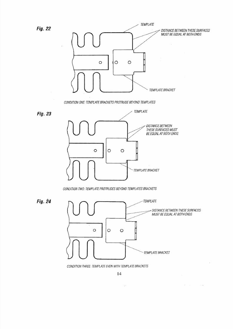
3) Movethetemplatefrom sideto sideonthe templatebracketsso that it is centeredwith respecto the templatebrackets,Thismeanshat
thetemplateandbracketsshouldlookIikeoneof the followingfigures:Figure22,Figure23,or Figure24,Movetemplateront-to-backsothat
front edgeof templateis parallelwith thefront of the dovetailbase.In eachconditionhetemplateandthetemplatebracketsMUSTbe
symmetricalwith eachother.Thefiguresdonot showthe completedovetailixture,butonly theunderneathsideof thetemplatewithtemplate
bracketscorrectlypositioned,n orderthat thecorrectpositionsof the partscanbeseenclearly.
]3
8/18/2019 Craftsman Dovetail Jig L0807067
http://slidepdf.com/reader/full/craftsman-dovetail-jig-l0807067 14/48
Fig. 22
I
TEMPLATE
_"DISTANCEETWEENHESEURFACES
MUSTBEEQUALTBOTHENDS
TEMPLATERACKET
CONDITIONONE."EMPLATERACKETSROTRUDEEYONDTEMPLATES
Fig. 23
o
j TEMPLATE
J
F
THESEURFACESUST
BEEQUALTBOTHENDS
_0 0 TEMPLATERACKET
CONDITIONWO;TEMPLATEROTRUDESEYONDTEMPLATESRACKETS
.24
o 0
0
MUSTBEEQUALTBOTHENDS
TEMPLATERACKET
CONDITIONTHREE.TEMPLATEVENWITHTEMPLATERACKETS
14
8/18/2019 Craftsman Dovetail Jig L0807067
http://slidepdf.com/reader/full/craftsman-dovetail-jig-l0807067 15/48
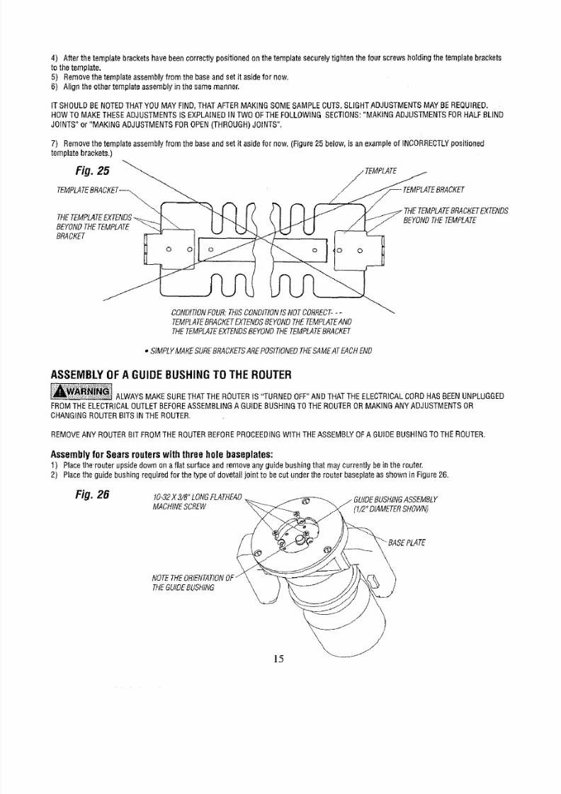
4) After thetemplatebracketshavebeencorrectlypositionedonthe templatesecurelytightenthefourscrewsholdingthetemptatebrackets
to thetemplate.
5) Removehetemplateassemblyromthebaseandsetit asidefornow.
6) Aligntheothertemplateassemblyn thesamemanner,
ITSHOULDBENOTEDTHATYOUMAYFIND,THATAFTERMAKINGSOMESAMPLECUTS,SLIGHTADJUSTMENTSAYBEREQUIRED.
HOWTOMAKETHESEADJUSTMENTSS EXPLAINEDNTWOOFTHEFOLLOWINGSECTIONS:MAKINGADJUSTMENTSORHALFBLIND
JOINTS"or "MAKINGADJUSTMENTSOROPENTHROUGH)OINTS".
7) Removehetemplateassemblyromthebaseandset it asidefornow.(Figure25 below,is anexampleof INCORRECTLYositioned
templatebrackets,)
CKET
BEYONDHETEMPLATE
BRACKET
0
o
o 0
THETEMPLATERACKETXTENDS
tEMPLATE
CONDITIONOUR:THISCONDITIONSNOTCORRECT--
TEMPLATERACKETXTENDSEYONDHETEMPLATEND
THETEMPLATEXTENDSEYONDHETEMPLATERACKET
• StMPLYMAKESUREBRACKETSREPOSITIONEDHESAMEATACHEND
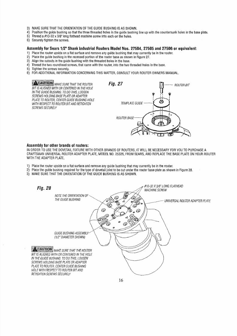
ASSEMBLY
OF
AGUIDEBUSHINGTOTHEROUTER
ALWAYSMAKESURETHATTHEROUTERS "TURNEDOFF"ANDTHATTHEELECTRICALORDHASBEENUNPLUGGED
FROMTHEELECTRICALUTLETBEFORESSEMBLING GUIDEBUSHINGOTHEROUTERORMAKINGANYADJUSTMENTSR
CHANGINGROUTERBITSINTHEROUTER.
REMOVEANYROUTERBITFROMTHEROUTERBEFOREPROCEEDINGITHTHEASSEMBLYOFA GUIDEBUSHINGOTHEROUTER.
Assembly for Sears routers with three hole baseplates:
1) Placethe'routerupsidedawnonaflat surfaceandremoveanyguidebushingthatmaycurrentlybein the router,
2) Placetheguidebushingrequiredfor thetypeof dovetagoint to becutundertherouterbaseplateasshownin Figure26.
Fig
26
10-32X 3/8°LONGFLATHEAD
MACHINECREW
(1/2"DIAMETERHOWN)
NOTETHEORIENTATIONF"
THEGUIDEUSHING
8/18/2019 Craftsman Dovetail Jig L0807067
http://slidepdf.com/reader/full/craftsman-dovetail-jig-l0807067 16/48
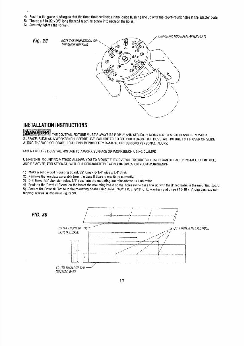
3) MAKESURETHATTHEORIENTATIONFTHEGUIDEBUSHINGS ASSHOWN,
4) Positiontheguidebushingsothatthethreethreadedholesinthe guidebushingineup withthe countersunkholesinthe baseplate.
5) Threada#10-32x 3/8"longflatheadmachinescrewinte eachonthe holes.
6) SecureIyightenthescrews.
Assembly
for Soars 1/2 Shank Industrial Routers Modal Nos.
27504,
27505 and 27506 or
equivalent:
1) Placeherouterupsideona flatsurfaceandremoveanyguidebushingthat maycurrentlybeinthe router.
2) Placeheguidebushingnthe recessedportionof therouterbaseasshownin Figure27.
3) Alignthecutoutsintheguidebushingwiththe threadedhoIesinthe base.
4) Threadthetwo roundheadcrews,thatcamewiththe router,intothetwo threadedholesinthe base.
5) Tightenthescrewssecurdy.
B) FORADDITIONALNFORMATIONONCERNINGHISMATTER,CONSULTOURROUTEROWNERSMANUAL.
MAKESURETHATTHEROUTER
BITISALIGNEDWITHORCENTEREDN THEHOLE
IN THEGUIDEBUSHING.TODOTHIS,LOOSEN
SCREWSHOLDINGBASEPLATEORADAPTER
PLATETOROUTER,CENTERGUIDEBUSHINGHOLE
WITHRESPECTOROUTERITANDRETIGHTEN
SCREWSSECURELY
Fig, 27 _ - ROUTERBIT
I i I
@
I
TEMPLATEUIDE-
ROUTERA_
Assembly for other brands of routers:
IN
ORDERTOUSETHEDOVETAILIXTUREWiTHOTHERBRANDSOFROUTERS,TWILL BENECESSARYORYOUTOPURCHASE
CRAFTSMANNIVERSALOUTERADAPTERLATE,MODELNO.25326,FROMSEARS,ANDREPLACEHEBASEPLATEONYOURROUTER
WITHTHEADAPTERPLATE.
1) Placethe routerupsideon aflatsurfaceandremoveanyguidebushingthatmaycurrentlybeinthe router,
2) Placetheguidebushingrequiredor thetypeof dovetailjointto becut undertherouterbaseplateas showninFigure2&
3) MAKESURETHATTHERIENTATIONFTHEGUIDEBUSHINGS ASSHOWN,
Fig. 28
NOTETHEORIENTATIONF
THEGUIDEUSHING
MACHINESCREW
(t/2"DIAMETERIlOWN)
MAKESURETHATTHEROUTER
BITtSALIGNEDWITHORCENTEREDNTHEHOLE
IN THEGUIDEBUSHING.TODOTHIS,LOOSEN
SCREWSHOLDINGBASEPLATEORADAPTER
PLATETOROUTER,CENTERGUIDEBUSHING
HOLEWITHRESPECTOROUTERITAND
RETIGHTENCREWSSECURELY
16
8/18/2019 Craftsman Dovetail Jig L0807067
http://slidepdf.com/reader/full/craftsman-dovetail-jig-l0807067 17/48

8/18/2019 Craftsman Dovetail Jig L0807067
http://slidepdf.com/reader/full/craftsman-dovetail-jig-l0807067 18/48
9) Applying smallamountofsoaptothe screwthreadswill makeit easierto threadthescrewsintothe holes.
10)Lineupthefront of themountingboardwiththe frontof a workbenchor othersturdysurface,
11)Usingtwo clamps,suchasC-clamps,irmly clampthe DovetailFixtureo theworkbenchbyclampingonthe mountingboardasshownIn
Figure31andFigure31A.
12)Makesurethatthemountingboardinesupwiththe frontof theworkbench.
Fig. 31
CLAMPHERE
\
k
• FRONTURFACEF
THEMOUNTtNG
BOARD
;URFACEF
THEWORKBENCH
FRONTURFACEFTHEBASE
Fig. 31,4
FRONTURFACEF -]
THEBASE
FRONTURFACEFTHE
MOUNTINGOARD
FRONTURFACEF/
THEWORKBENCH
USINGTHEDOVETAILFIXTURE
STYLES OF DOVETAILJOINTS
Fourdifferentstylesofdovetadointscanbemadewiththe DovetailFixtureusingyourrouter.
• Thesejointsaredescribednthefollowingsections.
Half Blind Flush Joint:
• TheHalfBlindFlushJointis usedwhentheheightof boththedrawerront andthedrawerbackisthe sameheightasthedrawersides;
andthe lengthof boththedrawerfrontandthedrawerbackis thesameasthewidthofthedrawer.
SeeFigure32.
18
8/18/2019 Craftsman Dovetail Jig L0807067
http://slidepdf.com/reader/full/craftsman-dovetail-jig-l0807067 19/48
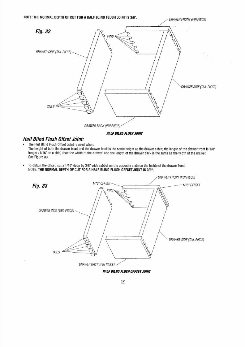
NOTE:THENORMALDEPTHOFCUTFORAHALFBLINDFLUSHJOINT
IS
3/8 .
_ DRAWERFRONT(PtNPtECE
Fig. 32
DRAWERIDE(TAILIECE)
J
DRAWERACKPiNPIECE)
SIDETAILPIECE)
HALFBILHDFLUSHOINT
HalfBlindFlushOffsetJoint:
TheHaftBlindFlushOffsetJoint is usedwhen:
Theheightof boththedrawerfrontandthedrawerbackisthesameheightasthe drawersides;the tengthof thedrawerfrontis 1/8"
longer(1/16"onaside)thanthewidth of thedrawer;andthe lengthof thedrawerbackis thesameasthewidth of thedrawer.
SeeFigure33.
Toobtaintheoffset,cuta 1t16"deepby 3/8"widerabbetontheoppositeendsonthe insideofthedrawerfront.
NOTE:THENORMALDEPTHOFCUTFORAHALFBLINDFLUSHOFFSETOINTS 3/8 ,
Fig. 33
_ DRAWERRONTPINPIECE)
DRAWERIDETAILPIECE)
DRAWERStDE(TAILPIECE)
TAILS
J
DRAWERACKPINPIECE)_
HALFBILNDFLUSHOFFSETOINT
19
8/18/2019 Craftsman Dovetail Jig L0807067
http://slidepdf.com/reader/full/craftsman-dovetail-jig-l0807067 20/48
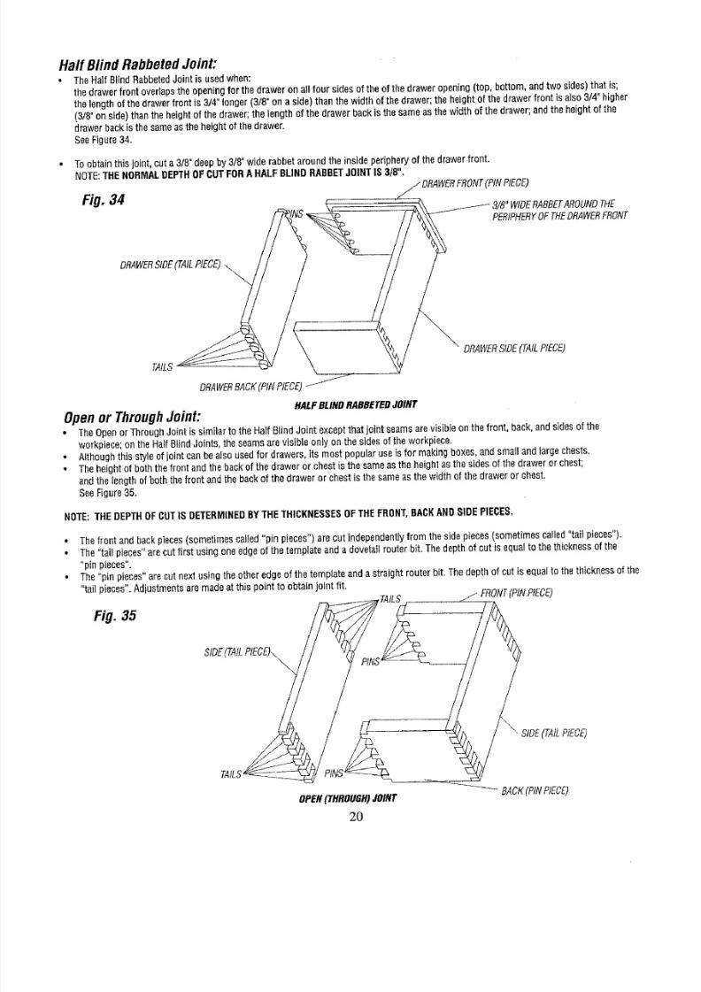
HalfBlindRabbetedJoint:
TheHalfBlindRabbetedointis usedwhen:
thedrawerfrontoverlapsheopeningor thedraweron allfour sidesof the
of
thedraweropening(top bottom andtwosides)thatis;
thelengthof thedrawerfrontis3/4 longer(3/8"on aside)thanthewidthof thedrawer;theheightof thedrawerfrontis also3/4"higher
(3/8°onside)thantheheightofthe drawer;he tengthof thedrawerbackisthesameas thewidthof thedrawer;andtheheightof the
drawerbackisthesameasthe heightof thedrawer
See
Figure
34
Toobtainthis
joint
cuta3/8"deepby3/8"wide rabbetaroundthe
inside
peripheryof
the
drawerfront
NOTE:
THENORMALDEPTHOFCUTFORAHALFBLINDRABBETOINTIS3/8 ,
/DRAWERFRONTPiNPIECE)
Fig. 4
"WIDERABBETAROUNDHE
PERIPHERYFTHEDRAWERRONT
DRAWERIDETAILPIECE)
\
DRAWERSIDE(TAILPIECE)
TAILS
DRAWERACKPINPIECE)
HALFBLINDRABBETEDOINT
Openor ThroughJoint:
• TheOpenorThroughJointis similar to theHalfB{indJoint exceptthatjointseamsarevisibieonthe front, back,andsidesof the
workpiece;on theHalfBlindJoints,theseamsarevisibleonlyonthesidesof theworkpiece,
•
Althoughthisstyleof
joint
canbealsousedfor drawersits mostpopularuseis for makingboxes,andsmallandfargochests
•
Theheightof boththefrontandthe backof thedraweror chestis thesameastheheightasthesidesof thedraweror chest;
andthe lengthof boththefrontandthebackof thedraweror chestIsthesameasthe widthof thedrawerorchest
SeeFigure35
NOTE:THEDEPTH
OF
CUTISDETERMINED
Y
THETHICKNESSES
F
THEFRONT,BACK
AND
SIDEPIECES,
• Thefrontandbackpieces(sometimescalledpin pieces")arecut independentlyrom thesidepieces(sometimescalledtail pieces)
• The'tail piecesarecutfirst usingoneedgeofthetemplateanda dovetailrouterbit Thedepthof cutis equalto thethicknessof the
pin pieces
The'pin pieces'arecutnextusingtheotheredgeof thetemplateanda straightrouterbit Thedepthof cutis equa{o the thicknessof the
taiI pieces Adjustmentsaremadeat thispoint toobtainjoint fit
Fig.
35 _ TAILS ii FRONTPtNPtECE)
TAILS --____ I \ RIDETAILPIECE)
OPENTHROUGH)OINT
_-_-_ BACKPtNPIECE)
2O
8/18/2019 Craftsman Dovetail Jig L0807067
http://slidepdf.com/reader/full/craftsman-dovetail-jig-l0807067 21/48
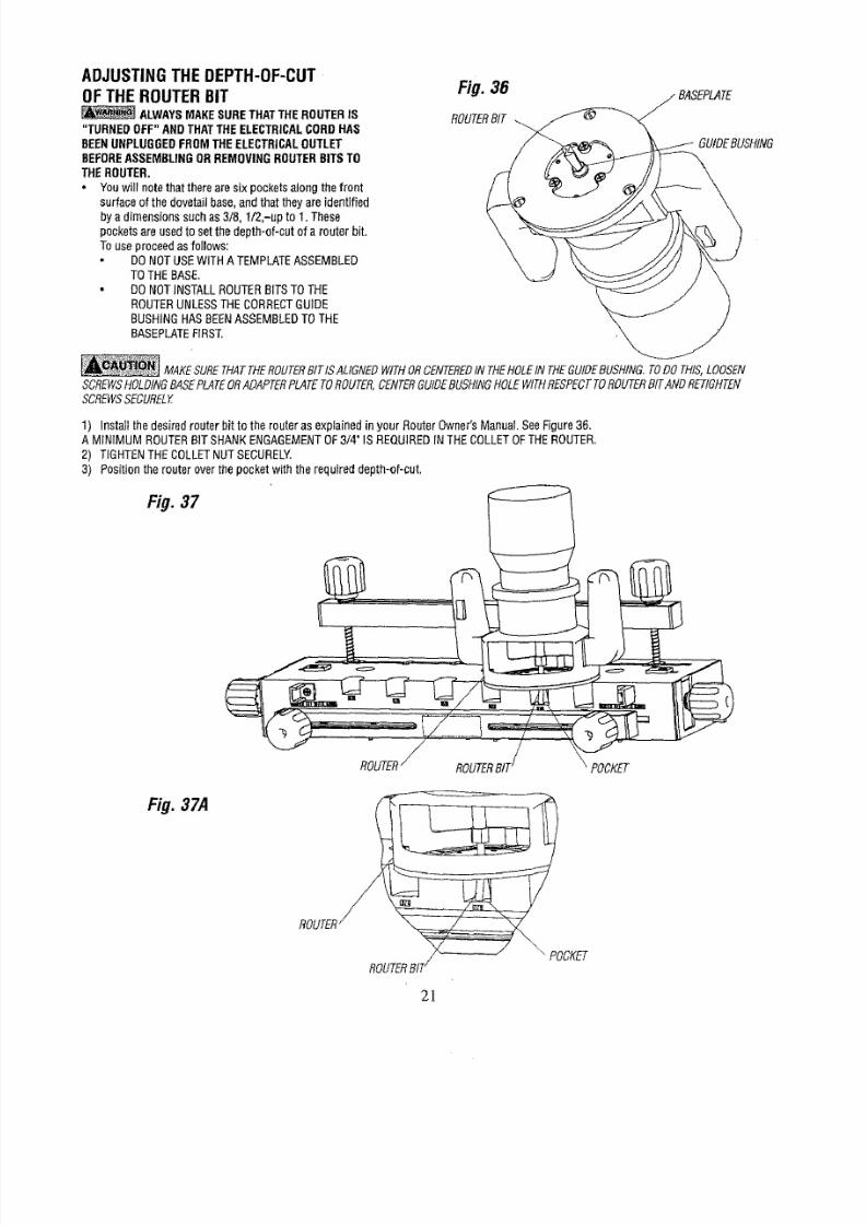
ADJUSTINGTHEDEPTH-OF-CUT
OFTHEROUTERBIT
ALWAYSMAKESURETHATTHEROUTERS
"TURNED
OFF ANDTHATTHEELECTRICALORDHAS
BEENUNPLUGGEDROMTHEELECTRICALUTLET
BEFORESSEMBLINGRREMOVINGOUTERBITSTO
THEROUTER,
• Youwill notethattherearesix pocketsalongthefront
surfaceof thedovetailbase,andthat theyareidentified
bya dimensionssuchas3/8, I/2,-up to1.These
pocketsareusedtosetthe depth-of-cutof a routerbit.
Touseproceedasfollows:
DONOTUSEWITHATEMPLATESSEMBLED
TOTHEBASE.
• DONOT
NSTALL
ROUTERBITSTOTHE
ROUTERUNLESSTHECORRECTUIDE
BUSHINGHASBEENASSEMBLEDOTHE
BASEPLATEIRST.
Fig. 36
ROUTERIT
GUIDEBUSHING
_ MAKESUREHATTHEROUTERITISALIGNEDWITHORCENTEREDNTHEHOLENTHEGUIDEUSHING.ODOTHIS,LOOSEN
SCREWSOLDINGASEPLATEORADAPTERLATEOROUTER,ENTERUIDEUSHINGOLEWITHlESPECTOROUTERITANDRETIGHTEN
SCREWSECUREDf
1) InstaIIthe desiredrouterbit to therouterasexp{ainednyour RouterOwner'sManual SeeFigure3B.
A M{NIMUMROUTERBITSHANKENGAGEMENTF3/4"IS REQUIREDNTHECOLLETOFTHEROUTER,
2) TIGHTENHECOLLETNUTSECURELY.
3) Positionthe routeroverthepocketwiththe requireddepth-of-cut,
Fig. 37
Fig.37A
2]
8/18/2019 Craftsman Dovetail Jig L0807067
http://slidepdf.com/reader/full/craftsman-dovetail-jig-l0807067 22/48
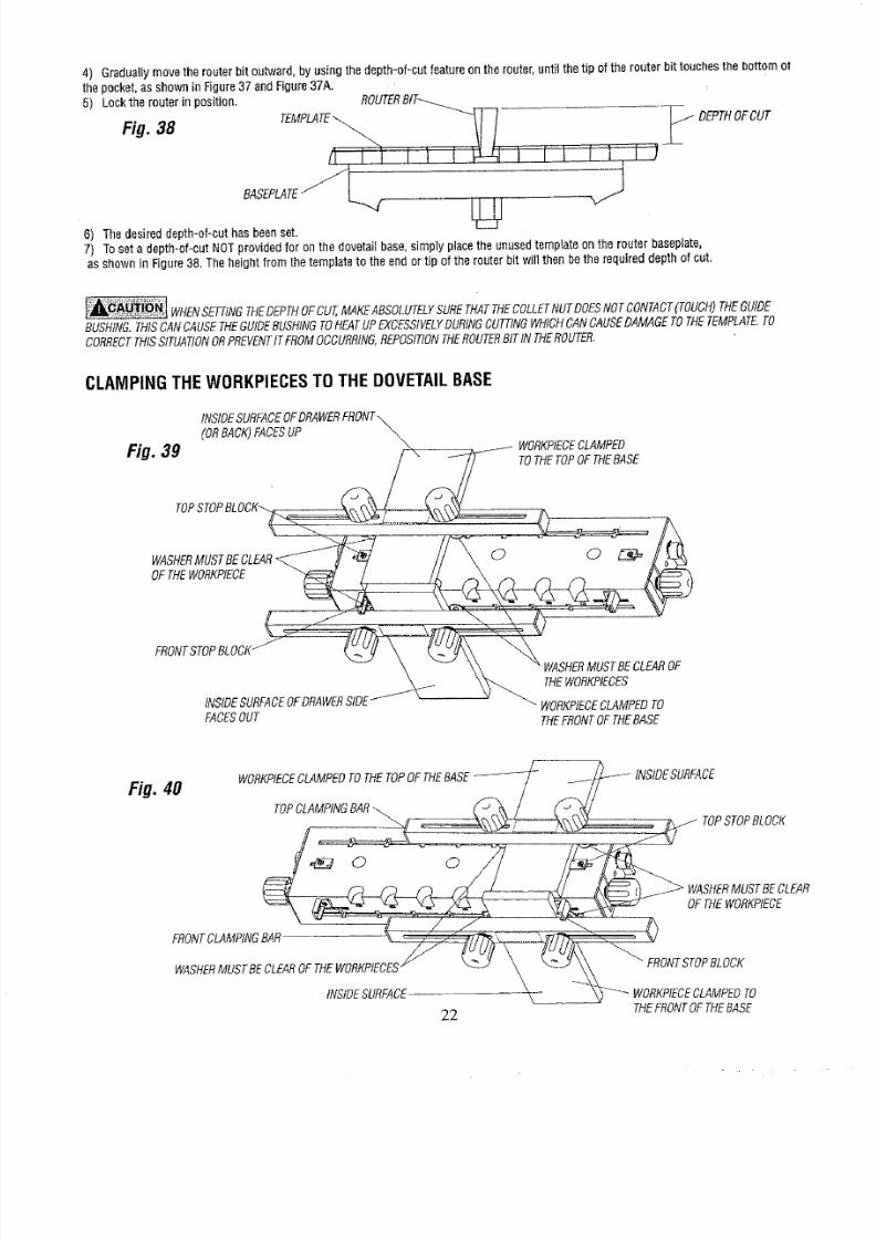
4) Graduallymovethe routerbit outward,by usingthedepth-of-cuteatureonthe router,
until
thetipof the routerbit touchesthebottomot
the pocket,as showninFigure37 andFigure37A.
5) Lockthe routerinposition,
Fig. 38 ?FOOT
6) Thedesireddepth-of-cuthasbeenset.
7) Toseta depth-of-cutNOTprovidedfor onthe dovetailbase,simplypJaceheunusedtemplateenthe routerbaseplate,
asshownin Figure38,Theheightfromthetemplateo theendor tip of therouterbitwill thenbethe requireddepthof cut,
WHENETTINGHEDEPTHOFcuT,MAKEABSOLUTELYUREHATTHECOLLETUTDOESNOTCONTACTTOUCH)HEGUIDE
BUSHING.HISCANCAUSEHEGUIDEUSHINGOHEATUPEXCESSIVELYURINGUTTINGWHICHANCAUSEAMAGEOTHETEMPLATE.O
CORRECTHISSITUATIONRPREVENTTFROMOCCURRING,EPOSITIONHEROUTERITNTHEROUTER.
CLAMPINGTHEWORKPIECESOTHEDOVETAILBASE
(ORBACK)FACESP
Fig. 39
TOTHETOPOFTHEBASE
TOP,
OFTHEWORKPIECB
FRONTTOPBLOCK-
FACESOUT
rBECLEAROF
THEWORKPIECES
WORKPtECELAMPEDO
THEFRONTOFTHEBASE
Fig, 40 WORKPIECELAMPEDOTHETOPOFTHEBASE-_-_-/ __i_-_- INSIDESURFACE
TOPC.MPINGB,
TOPSTOPRLOBK
ERO_TLAMPINGBAR-_
WASHER,_,fUSTBE_ORKP_CES¢\ __J_ "_TSTOPBLOCK
INStOESUREADE
_-
'_-'--WORKPIEOECLAMPEO
2,2, THEFRONTOFTHEBASE
8/18/2019 Craftsman Dovetail Jig L0807067
http://slidepdf.com/reader/full/craftsman-dovetail-jig-l0807067 23/48
• Theclampingarshavebeenspeciallydesignedo allowtheclampingorcestobeappliednextto theworkpiecesormoreefficient
clamping.
his
is
accomplishedbybeingableto positionthe
clamping
nobs
inclose
proximityornextto the
workpieces.
• Figure39 illustratesthepositioningof theclampingarsand theclampingknobswhentheworkpiecesareclampedo the LEFTSIDEof
theDovetailFixture,
Figure40 illustrateshe positioningof theclampingbarsandtheclampingknobswhentheworkpiecesareclampedo the RIGHTSIDEof
the DovetailFixture.
* Notetheclosenessfthe clampingnobsto the workpieces.Whennot inuseclampingknobsandthe supportingboltsandspringsare
freeto bemovedalongthe slotsinthe base,
• CAUTION:WHENCLAMPING,MAKESURETHATTHECLAMPINGKNOBSARENOTPOSITIONEDOCLOSETOTHEWORKPtECESHAT
THEWASHERSBECOMERAPPEDUNDERTHEWORKPIECES.
• FORACCURATEOINTS,THEWORKPIECESUST"Bu]-r-uP" AGAINSTOTHTHETOPANDTHEFRONTSTOPBLOCKSOENSURE
THEEXACTPOSITIONINGFTHEWORKPIECES.
* TOENSUREACCURATEOINTSANDSAFEOPERATION,OODSHAVINGSNDACCUMULATED
UST
MUSTBE
REMOVED
ROMTHE
DOVETAILIXTUREBEFOREACHSETUP,EITHERBYUSINGABRUSHOR BYVACUUMING.
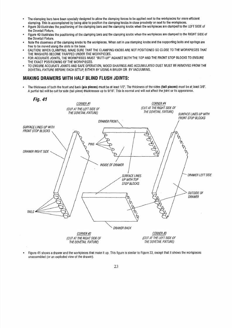
MAKINGDRAWERSWITHHALFBLINDFLUSHJOINTS:
•
The
thicknessof boththe frontandback(pin
pieces)
mustbeat least1/2".
The
thicknessofthe sides(tail
pieces)
mustbeat least3/8".
A partialtailwill becatfor side(tailpiece)thicknessesupto 9/16".Thisisnormalandwill notaffectthejointor its appearance.
Fig. 41
SURFACEINESUPWITH
FRONTTOPBLOCKS
DRAWERIGHTIDE
CORNER1
(CUTATTHELEFTSIDEOF
THEDOVETAILIXTURE)
CORNER4
(CUTATTHERIGHTSIDEOF
THEDOVETAILIXTURE)
DRAWERRONT_
PINS_ /
INSIDEOFDRAWER
STOPBLOCKS
_ DRAWERACK
CORNER2
(CUTATTHERIGHTSIDEOF
THEDOVETAILIXTURE)
CORNER3
(CUTATTHELEFTSIDEOF
THEDOVETAtLIXTURE)
SURFACEINESUPWITH
FRONTTOPBLOCKS
OUTSIDEF
DRAWER
• Figure41 showsa drawerandtheworkpieceshatmaket up.Thisfigureis similartoFigure33,exceptthatit showsthe workpieces
unassembledor anexplodedviewof thedrawer).
23
8/18/2019 Craftsman Dovetail Jig L0807067
http://slidepdf.com/reader/full/craftsman-dovetail-jig-l0807067 24/48
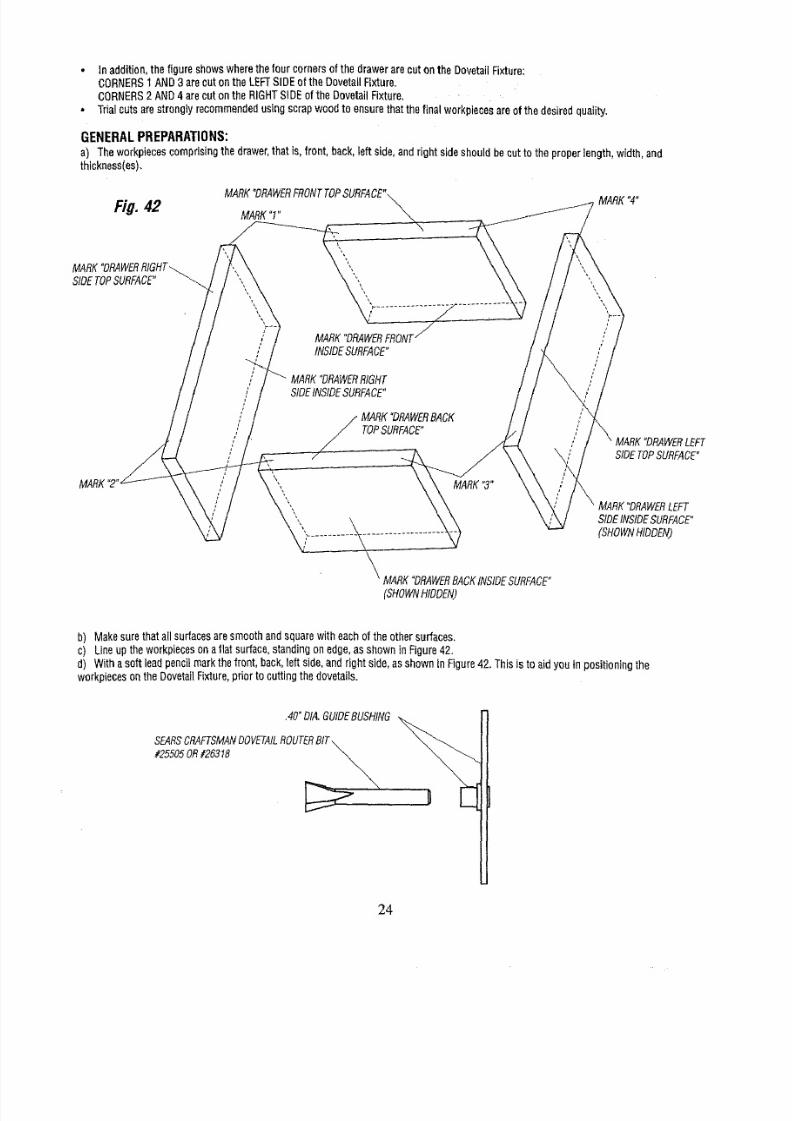
• Inaddition,thefigure showswherethefourcornersof thedrawerarecutonthe DovetailFixture:
CORNERSAND3 arecotontheLEFTSIDEof the DovetailFixture,
CORNERSAND4 areouton theRIGHTSiDEof the DovetailFixture.
• Trialcutsarestronglyrecommendedsingscrapwoodto ensurethat thefinalworkpieceeareofthe desiredquaIity,
GENERALPREPARATIONS:
a) Theworkpiecesomprisingthedrawer,hat is,front,back,left side,andrightsideshouldbeoutto theproperength,width,and
thickness(es),
Ei#. 42
MARK1"
MARK°DRAWERIOHT /_ _",,
_ MARKDRAWERACKNSIDESURFACE"
_HOWN_DDEN)
MARK4"
SIDETOPSURFACE"
MARKDRAWEREFT
SIDENSIDEURFACE"
(SHOWNIDDEN)
b) Makesurethatallsurfacesaresmoothandsquarewith eachoftheothersurfaces,
c) Lineuptheworkpiecesonaflatsurface,standingonedge,asshownin Figure42.
d) Withasoftleadpencilmarkthefront,back,eftside,andrightside,asshownInFigure42.Thisis to aidyou
workpiecesonthe DovetailFixture,priortocuttingthedovetails•
positioningthe
•40"DIA.GUIDEUSHING
SEARSRAFTSMANOVETAILOUTERIT\ _
#25505OR#26318
24
8/18/2019 Craftsman Dovetail Jig L0807067
http://slidepdf.com/reader/full/craftsman-dovetail-jig-l0807067 25/48
e) Assemble
he
.40"guidebushingto therouterbaseplate,asdescribedn aprevioussection.Thisthesmallerof thetwoguidebushings
furnishedwiththis product.
f) _nsta__Searsd_vetai_r_uterbit_#255_5_r#26318_t_ther_uterasdescribed_ny_urR__ter_wner_sManuaLShankengagement
shouldbea minimumof 3/4%
_ MAKESURETHATTHEROUTERITtSALIGNEDWITHORCENTEREDNTHEHOLENTHEGUIDEUSHING.ODOTHIS,OOSEN
SCREWSOLDtNGASEPLATEORADAPTERLATETOROUTER,ENTERUIDEUSHINGOLEWITHRESPECTOROUTERtTANDRETtGHTEN
SCREWSECURELY.
_ WHENETTINGHEDEPTHOFCUT,MAKEABSOLUTELYURETHATHECOLLETUTDOESNOTCONTACTTOUCH)HEGUIDE
BUSHING.HISCANCAUSEHEGUIDEUSHINGOHEATUPEXCESSIVELYURINGUTTINGHICHCANCAUSEAMAGEOTHETEMPLATE,O
CORRECTHISSITUATIONRPREVENTTFROMOCCURRING,EPOStTtONHEROUTERITINTHEROUTER.
Fig. 43
' LEFTTOPSTOPLOCK
/"A"FACESOWARDIDDLE
j OFBASE
RIGHTTOPSTOPLOCK
j POINTERPOINTS
TOCENTER
GRADUATION
LEFTFRONTTOPBLOCK
STOPBLOCK
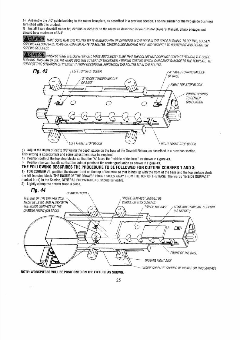
g) Adjust thedepthofcutto 3/8"usingthedepthgaugeonthebaseof theDovetailFixture,asdescribedn a previoussection.
Thissettingis approximateandsomeadjustmentmayberequired.
h) Positionbothof thetopstopbIocksso thatthe"A" facesthe "middleof thebase"asshowninFigure43.
i) Positionthecamhandlesothatthepointerpointsto thecentergraduationasshowninFigure43.
THE FOLLOWING DESCRIBESTHE PROCEDURE
TO
BEFOLLOWEDFORCUTTING CORNERS 1 AND 3:
1) FORCORNER1, positionhe drawerfronton thetopof thebaseso thatit linesupwith thefrontof thebaseandthetop surfaceabuts
the left top stopblock.THEINSIDEOFTHEDRAWERRONTFACESAWAYFROMTHETOPOFTHEBASE.Thewords"INSIDESURFACE"
markedin (d) in theSection,GENERALREPARATIONS,houldbevisible.
2) Lightlyclampthedrawerfront inplace.
Fig. 44
DRAWERRONT
THEENDOFTHEDRAWERIDE
MUSTBELEVELNDF
THENSIDEURFACEFTHE
DRAWERRONTORBACK)
"INSIDESURFACE"HOULDBE
VIStBLEON THISSURFACE
TOPOFTHEBASE _MPLATEUPPORT
(ASNEEDED)
FRONTOF THEBASE
NOTE:WORI(PIECESWILL BEPOSITIONEDONTHEFIXTUREASSHOWN.
"INSIDESURFACE"HOULDBE VISIBLEONTHISSURFACE
25
8/18/2019 Craftsman Dovetail Jig L0807067
http://slidepdf.com/reader/full/craftsman-dovetail-jig-l0807067 26/48
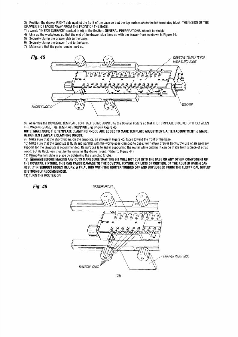
3) PositionthedrawerRIGHTsideagainstthefront ofthe basesothatthe top surfaceabutstheleft frontstopblock.THEINSIDEOFTHE
DRAWERSIDEFACESAWAYFROMTHEFRONTOFTHEBASE.
Thewords "INSIDESURFACE"markedin (d) Inthe Section,GENERALPREPARATIONS,houldbevisible.
4) Lineuptheworkpieeesso thattheendof thedrawersidelinesupwiththedrawerfront asshownin Figure44.
5) Securelyclamphedrawersideto thebase,
6) Securelyclampthedrawerfrontto thebase.
7) Makesurethatthepartsremaingnedup.
Fig. 45
HALFBLINDOINT
SHORTINGERS WASHER
8) AssembLehe DOVETAILEMPLATEORHALFBLINDJOINTSo the DovetagFixturesothatTHETEMPLATERACKETSITBETWEEN
THEWASHERSNDTHETEMPLATEUPPORTSsshownFigure45.
NOTE:MAKESURETHETEMPLATELAMPINGNOBSARELOOSETOMAKETEMPLATEDJUSTMENT,FTERADJUSTMENTSMADE,
RETIGHTENEMPLATELAMPINGNOBS.
9) Makesurethattheshort
fingers
onthetemplate,as shownin Figure45, facestowardthefront of the base.
10)Makesurethat thetemplates flushandparallelwiththe workpiecesclampedo base.Fornarrowdrawerfronts, the useofanauxifiary
supportfor thetemplates recommended.tspurposes to aidin supportingtherouterwhilecutting.It canbemadefroma pieceof scrap
wood;butits thicknessmustbethe sameasthe drawerfront.(Referto Figure44).
1 ) Clamphe templaten placeby tighteningtheclampingknobs.
12) _ BEFDREMAKINGANYCUTSMAKESURETHATTHEBITWILLNOTCUTINTOTHEBASEORANYOTHERCOMPONENTF
THEDOVETAILIXTURE.THISCANCAUSEDAMAGEOTHEDOVETAILIXTURE;ORLOSSOFCONTROLFTHEROUTERWHICHCAN
RESULTNSERIOUSBODILYNJURY.ATRIALRUNWITHTHEROUTERURNEDOFFANDUNPLUGGEDROMTHEELECTRICALUTLET
ISSTRONGLYECOMMENDED,
13)TURNTHEROUTERON,
Fig. 46
j DRAWERRIGHTSIDE
DOVETAILUTS
26
8/18/2019 Craftsman Dovetail Jig L0807067
http://slidepdf.com/reader/full/craftsman-dovetail-jig-l0807067 27/48
14)Cutthedovetailby movingthe routerfromLEFTTORIGHT,with theguidehushingfollowingthetemplate,DONOTFORCENYTHING;
MOVETHEROUTERNSLOWANDSMOOTHFASHION.
15)Toensureasmoothanduniformjoint, retracethe previouscutby movingtherouterfrom RIGHTTOLEFTwith theguidebushingagain
followingthe template.
16)_ NEVERLIFTTHEROUTERUPWARDSWHENTHEROUTERSONANDTHEROUTERBITROTATINGRWHENTHEGUIDE
BUSHINGSNEARTOORTOUCHINGHETEMPLATE.HISCANCAUSEDAMAGEOTHEDOVETAILIXTURE;ORLOSSOFCONTROLOF
THEROUTERWHICHCANRESULTNSERIOUSBODILYNJURY,
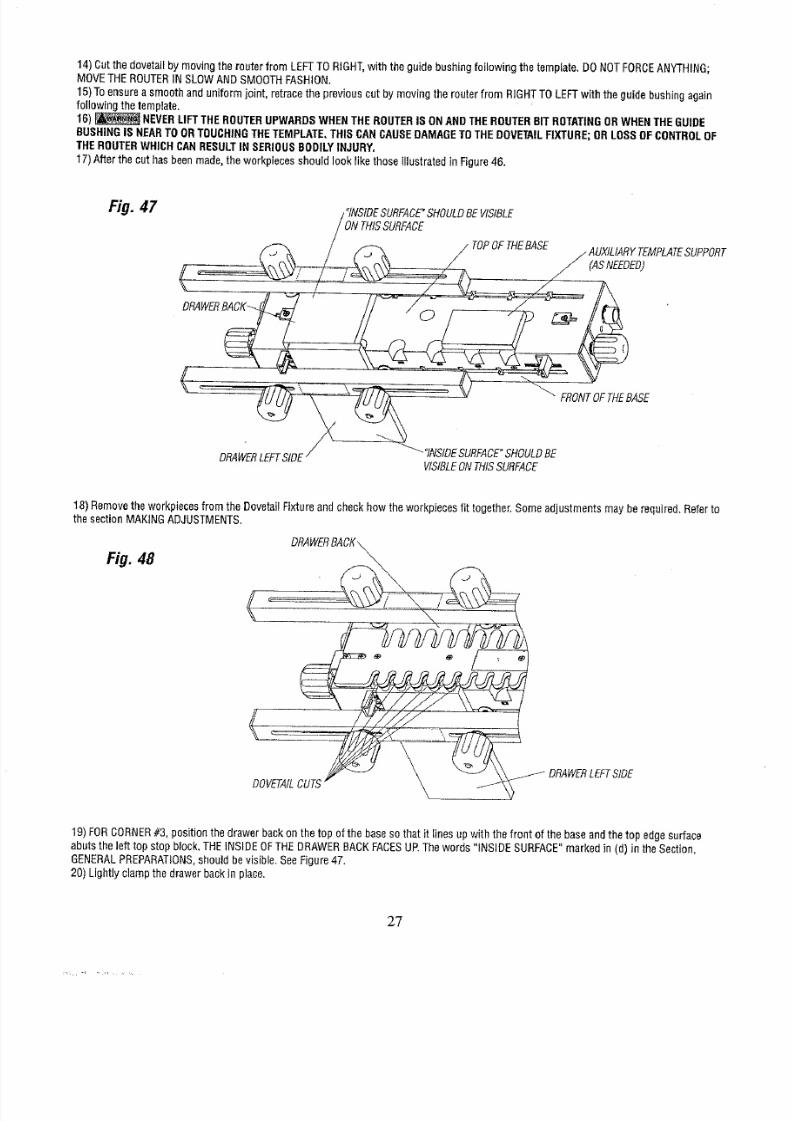
17)Afterthecut hasbeenmade,heworkpiecesshouldlooklikethoseIllustratedn Figue46.
Fig. 47
/"INSIDESURFACE"HOULDEVISIBLE
_/(,_ /ONTHISSURFADE
TOPOFTHEBASE / AUXILIARYEMPLATEUPPORT
(ASNEEDED)
DRAWERACK
-
_ "
SE
VISIBLENTHISSURFACE
18)Removeheworkpiecesromthe DovetailFixtureandcheckhowtheworkpiecesit together.Someadjustmentsmayberequired,Referto
thesectionMAKINGADJUSTMENTS.
Fig. 48
DOV_A£__
DRAWEREFTSIDE
19)FORCORNER3,positionthedrawerbackonthe topofthebaseso thatit linesupwiththe front of thebaseandthetop edgesurface
abutstheleft topstop block.THEINSIDEOFTHEDRAWERBACKFACESUP.Thewords "iNSIDESURFACE"markedin (d) intheSection,
GENERALREPARATIONS,houldbevisible,SeeFigure47.
20)Lightlyclampthedrawerbackin place.
g?

8/18/2019 Craftsman Dovetail Jig L0807067
http://slidepdf.com/reader/full/craftsman-dovetail-jig-l0807067 28/48
21)PositionthedrawerLEFTsideagainstthefront of thebaseso thatthetop surfaceabutsthe leftfront stop block.THEINSIDEOFTHE
DRAWERSIDEFACESUP.Thewords"INSIDESURFACE"markedin (d)in theSection,GENERALREPARATIONS,houIdbevisible.
22)Lineupthe workpiecesso thatthe endof thedrawersidelinesup withthedrawerbackasshownin Figure47.
23)Continueas
in
Steps5 through16above.
24)Afterthe cut hasbeenmade,the workpiecesshould looklike thoseillustratedn Figure48.
25)Removehe workpiecesromthe DovetailFixtureandcheckhowtheworkpiecesit together.Someadjustmentsmayberequired.
Referto the sectionMAKINGADJUSTMENTS.
THEFOLLOWING DESCRIBESTHE PROCEDURE TO 8E FOLLOWEDFOR CUTTING CORNERS 2 AND 4:
CORNERSAND4 arecut in thesamewayas 1and3 excepttheyarepositionedonthe rightsideof theDovetailFixtureas shownFig49.
Fig. 49
AUXtLIARYEMPLATEUPPORT
(ASNEEDED)
tNTHISSURFACE
/
FRONTOFTHEBASE
ORAWERtGHTSIDE
"INSIDEURFACE"HOULDEVISIBLENTHISSURFACE
NOTE:WORKPIECESILLBEPOSITIONEDNTHEFIXTUREASSHOWN.
_BEFORE
MAKINGANYCUTSMAKESURETHATTHEBITWILLNOTCUT
INTO
THEBASEORANYOTHERCOMPONENTFTHE
DOVETAILIXTURE.THISCANCAUSEDAMAGEOTHEDOVETAILIXTURE.
_NEVER
LIFT
THE
ROUTERUPWARDSWHENTHEROUTERSONANDTHE
ROUTER
BITROTATINGRWHENTHEGUIDE
BUSHING
SNEAR
TOORTOUCHINGHETEMPLATE.HISCANCAUSEDAMAGEOTHE
DOVETAIL
IXTURE.
Afterthecut hasbeenmade,theworkpieeesshouldlooklikethoseillustratedn Figure45.
Thefinishedfront, back,andsidesshouldlooklikethose in Figure41.
Beforegluingthefront,back,andsidestogethez;omepmvisienmust
be
madefor installinghebottom,suchasdadoingorcatting
e
groovearoundheinsideofthedrawerparts.
Yourdraweris nowreadyto begluedtogether,
MAKINGDRAWERSWITHHALFBLINDFLUSHOFFSETJOINTS:
GENERALPREPARATIONS:
a) Thelengthof thedrawerfront {s1/8_longerthanthe lengthofthe drawerbeck.
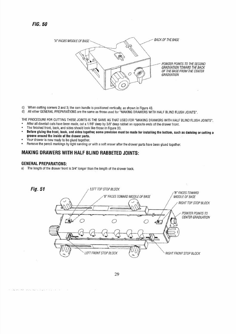
b) Whencuttingcornersl and4;thecam handleis rotatedtwo graduationsowardthebackof thebase,hus movingthe template1/32"
towardthebackof thebase.(Referto Figure50).
NOTE:MAKESURETHETEMPLATELAMPINGKNOBSARELOOSETOMAKETEMPLATEDJUSTMENT.FTERADJUSTMENT
S
MADE,
RETIGHTENEMPLATELAMPINGNOBS.
28
8/18/2019 Craftsman Dovetail Jig L0807067
http://slidepdf.com/reader/full/craftsman-dovetail-jig-l0807067 29/48
FIG.50
°A FACESfDDLEOFEASE
GRADUAtiONOWARDHEBACK
OFTHEBASEFROMTHECENTER
GRADUAtiON
c) Whencuttingcorners2and3;the camhandleis positionedvertically,asshowninFigure4&
d) All otherGENERALPREPARATIONSrethesameasthoseusedfor "MAKINGDRAWERSWITHHALFBLINDFLUSHJOINTS",
THEPROCEDUREORCUTTINGHESEOINTSSTHESAMEASTHATUSEDFOR"MAKINGDRAWERSWITHHALFBLINDFLUSHJOINTS".
Afteralldovetailcutshavebeenmade,cuta 1/16"deepby3/8"deeprabbetonoppositeendsofthedrawerfront.
• Thefinishedfront, back,andsidesshouldlook likethoseinFigure33.
Beforegluingthefront,back,andsidestogethez;omeprovisionmustbemadeforinstallingthebottom,suchasdadoingorcuttinga
groovearoundheinsideofthedrawerpads.
Yourdrawerisnow readyto begluedtogether.
•
Removehe pencilmarkingsby lightsandingor witha softeraserafterthedrawerpartshavebeengluedtogether.
MAKINGDRAWERSWITHHALFBLINDRABBETEDOINTS:
GENERALPREPARATIONS:
a) Thelengthof thedrawerfront is 3/4"longerthanthelengthof thedrawerback.
Fig. 51
LEFTTOPSTOPBLOCK
/_"B" FACESOWARDIDDLEOFBASE
/ POINTEROINTSTO
CENTERRADUAtiON
29
8/18/2019 Craftsman Dovetail Jig L0807067
http://slidepdf.com/reader/full/craftsman-dovetail-jig-l0807067 30/48
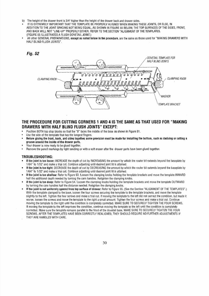
b) Theheightofthe drawer
front
is 3/4"higherthanthe heightof the drawerbackanddrawersides.
IT IS EXTREMELYMPORTANTHATTHETEMPLATEEPROPERLYLIGNEDWHENMAKINGTHESEOINTS,ORELSE,N
ADDITIONTOTHEJOINTSPACINGNOTBEINGEQUAL,ASSHOWNNFIGURE5BELOW,HETOPSURFACESFTHESIDES,FRONT,
ANDBACKWILLNOT"LINE-UP"PROPERLYITHER.REFEROTHESECTIONALIGNMENTOFTHETEMPLATES.
(FIGURE5 ILLUSTRATESFLUSHDOVETAILOINT.)
AgotherGENERALREPARATIONS,xceptasnotedbelowntheprocedure,rethe sameasthoseusedfor "MAKINGDRAWERSWITH
HALFBLINDFLUSHJOINTS".
Fi . 52
/ DOVETAILEMPLATEOR
LFBLINDOINTS
THEPROCEDUREORCUTTINGCORNERS1AND4 IS THESAMEASTHATUSEDFOR
"MAKING
DRAWERSWITH HALFBLINDFLUSHJOINTS EXCEPT:
PositionBOTHop stopblocksso thatthe "B" facesthe middieof thebaseasshownin Figure51,
Usethe sideof thetemplatehathasthelongestfingers,
Beforegluingthe Iront,back,andsidestogethez;omeprovisionmustbemadefor installing thebottom,suchasdadoingor cuttinga
groovearoundheinsideofthedrawerparts.
Yourdrawers nowreadyto begluedtogether.
Removehe pencilmarkingsby light sandingorw tha soft eraserafterthe drawerpartshavebeengluedtogether.
TROUBLESHOOTING:
• If thejoint istooloose: iNCREASEhe depthof cut by INCREASINGheamountbywhichtherouterbit extendsbeyondhe basepiateby
1164"to 1/32"andmakea trialcut.Continueadjustinguntil desiredoint fit is attained,
* Ifthe jointis tootight: DECREASEhedepthof cutby DECREASINGheamountbywhichtherouterbit extendsbeyondhe baseplateby
1/64" to 1/32"andmakeatriaI cut.Continueadjustinguntildesiredointfit isattained.
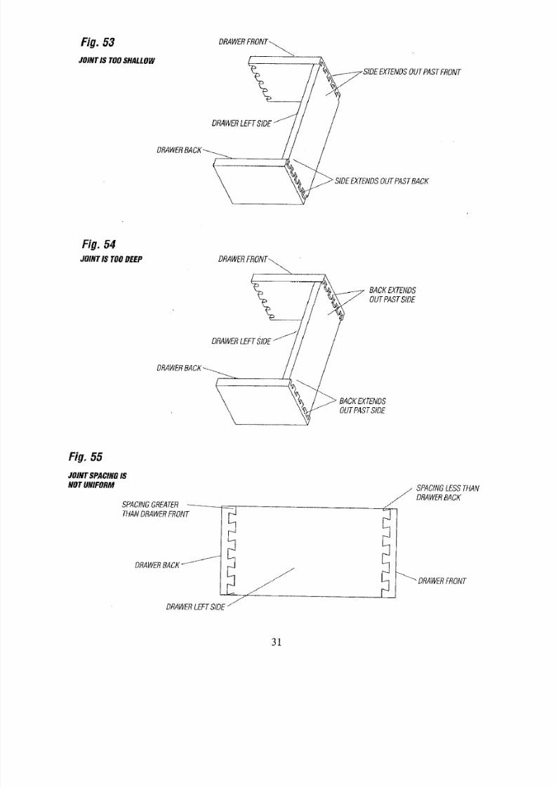
• If the joint is tooshallow:Refero Figure53.LoosenheclampingknobsholdingthetemplatebracketsandmovethetemplateINWARD
halfthe additionaldepthneededby turningthe camhandles.Retightenhe clampingknobs.
• It the joint is toodeep:Refero Figure54.LoosentheclampingknobsholdingthetemplatebracketsandmovethetemplateOUTWARD
by turningthecamhandleshalfthedistanceneeded.Retightenhe dampingknobs.
• If the jnint isnotunilormlyspacedtramtop surfaceofdrawer:Referto Figure55. (Seehe Section"ALIGNMENTOFTHETEMPLATES",)
Withthe templateclampedo the base,loosenthefour screwssecuringhetemplateto thetemplatebrackets,andmovethetemplate
slightlyto the Iuft.Tightenhefourscrewsandmakeatrial cut.If movingthetemplateto the leftdidnotcorrectthecondition,butmadeit
worse,loosenthe screwsandmovethetemplateto the righta smallamount.Tightenthefour screwsandmakeatriai cut.Continue
movingthetemplateto the rightuntilthe conditionis completeIycorrected,MAKESURETOSECURELYIGHTENHEFOURSCREWS.
it movingthe templateo theleft improvesthecondition,continuemovingthe templateo the leftuntiltheconditionis completeiy
corrected.Makesurethetemplateremainsparagelo thefront of thedovetailbase.MAKESURETOSECURELYIGHTENHEFOUR
SCREWS.AFTERTHETEMPLATESAVEBEENCORRECTLYEALIGNED,HEYSHOULDREQUIREOFURTHERDJUSTMENTSF
THEYAREHANDLEDWITHCARE.
3O
8/18/2019 Craftsman Dovetail Jig L0807067
http://slidepdf.com/reader/full/craftsman-dovetail-jig-l0807067 31/48
Fig. 53
JOINTIS TOOSHALLOW
DRAWERRONT_
FRONT
DRAWEREF:
DRAWERA
\
Fig. 54
JOINTIS TOODEEP
BACKEXTENDS
OUTPASTSIDE
DRAWEREFT
DRAWERA
OUTPASTS_E
Fig.55
JOINTSPACINGS
NOTUNIFORM
DRAWERACKz- L_I_
jJ
DRAWEREFTSIDEj_
J
J
_,/ SPACINGESSTHAN
DRAWERACK
31
8/18/2019 Craftsman Dovetail Jig L0807067
http://slidepdf.com/reader/full/craftsman-dovetail-jig-l0807067 32/48
Fig. 58
CORNER#1
PROJECTFRONA_
CORNER#4
SURFACEINES
UPWITHFRONT
STOPBLOCKS
PROJECTRtGHTSIDE_._
_ SURFACE
FRONTTOPBLOCK
OUTSIDEF
PROJECT
TAtL_
CORNER2 "" PROJECTACK
PROJECT
CORNER#3
SIDE
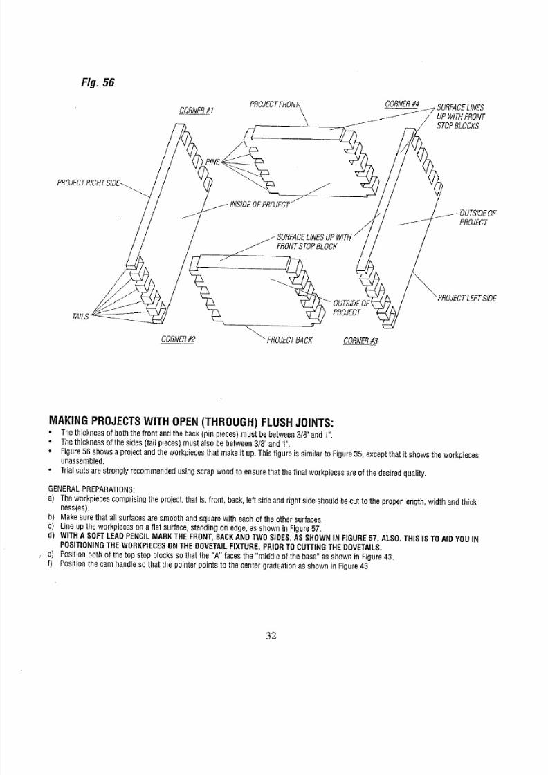
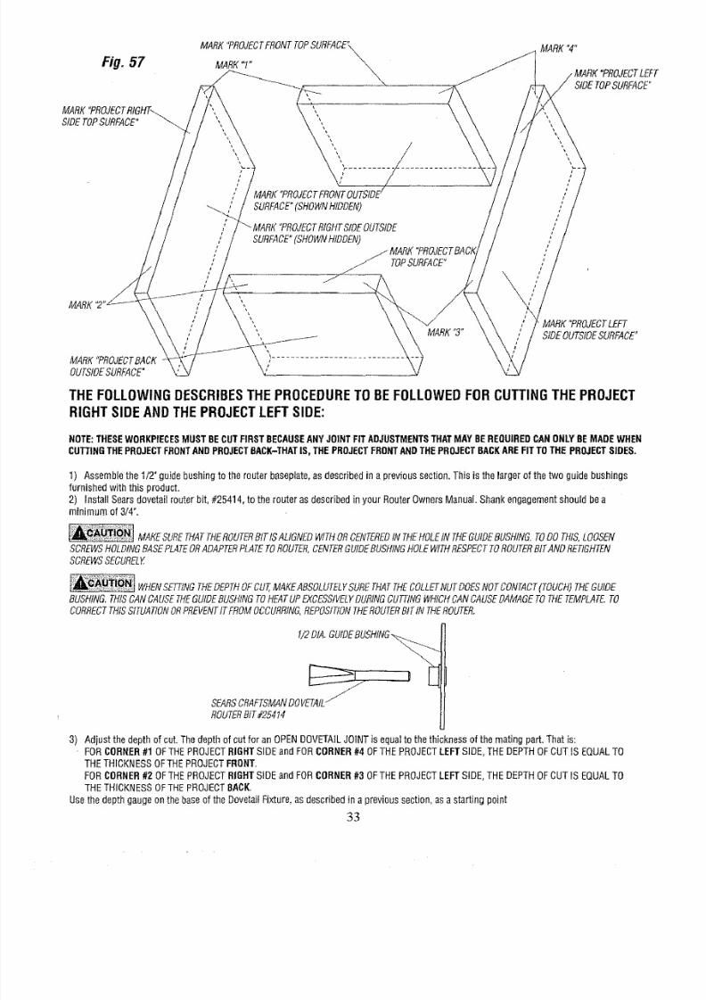
MAKINGPROJECTSWITHOPEN(THROUGH)FLUSHJOINTS:
• Thethicknessof boththefront andtheback(pinpieces)mustbebetween3/8"and1".
Thethicknessof the sides(tail pieces)mustalsobebetween3/8"and1".
Figure56showsa projectandthe workpieceshatmakeit up.Thisfigureissimilar toFigure35,exceptthatit showstheworkpieces
unassembled.
Trialcutsarestronglyrecommendedsingscrapwoodto ensurethatthefinalworkpiecesareof the desiredquality.
GENERALPREPARATIONS:
a) Theworkpiecescomprisingheproject,thatis, front, back,Ieftsideandrightsideshouldbecut to theproperlength,widthandthick
ness(es).
b) Makesurethat allsurfacesaresmoothandsquarewith eachof theothersurfaces.
c) Lineup theworkpiecesona flatsurface,standingon edge,asshownin Figure57,
d)
WITHASOFTLEAD
PENCIL
MARKTHEFRONT,BACKANDTWOSIDES,ASSHOWN
N
FIGURE57, ALSO,THIS
IS
TO
AID
YOU
IN
POSITIONINGHEWORKPIECESNTHEDOVETAILIXTURE,PRIORTOCUTTINGHEDOVETAILS,
e) Positionbothof thetop stopblocksso thatthe "A"facesthe"middleofthe base"asshownin Figure43.
f) Positionthecamhandlesothatthe pointerpointsto thecentergraduationasshownin Figure43.
32
8/18/2019 Craftsman Dovetail Jig L0807067
http://slidepdf.com/reader/full/craftsman-dovetail-jig-l0807067 33/48
Fig. 57
MARKPROJECTIGHT_
SIDETOPSURFACE
MARK"PROJECTRONTTOPSURFACE"\
MARK" " \,,\\
%
l
--_. SURFACE"SHOWNHIDDEN)
SURFACE"SHOWNHIDDEN)
TOPSURFACE"
MARK4"
TLEFT
SIDE
TOP
SURFACE
MARK
MARK"PROJECTACK
OUTSIDEURFACE"
MARK3"
MARK"PROJECTEFT
SIDEOUTSIDEURFACE"
THEFOLLOWINGDESCRIBESHEPROCEDUREOBEFOLLOWEDFORCUTTINGTHEPROJECT
RIGHTSIDEANDTHEPROJECTLEFTSIDE:
NOTE:THESEWORKPIECESMUST BECUTFIRSTBECAUSEANYJOINTFITADJUSTMENTSTHATMAYBEREQUIREDCANONLYBEMADEWHEN
CUTTINGTHEPROJECTFRONTANDPROJECTSACK-THATS, THEPROJECTFRONTANDTHEPROJECTBACKAREFITTOTHE PROJECTSIDES,
1) Assemblehe 1/2_guidebushingtotherouterbaseplate,sdescribedna previoussection,Thiss thelargerof thetwo guidebushings
furnishedwiththis product.
2) InstallSearsdovetailrouterbit,#25414,to the routerasdescribednyourRouterOwnersManual.Shankengagementshouldbea
minimumof 3/4".
MAKESUREHATTHEROUTERITISALIGNEDWITHORCENTEREDNTHEHOLENTHEGUIDEUSHING.ODOTHIS,LOOSEN
SCREWSOLDINGASEPLATERADAPTERLATEOROUTER,ENTERUIDEUSHINGOLEWITHRESPECTOROUTERITANDRETIGHTEN
SCREWSECURELY
WHENSETTINGTHEDEPTHOFCUT,MAKEABSOLUTELYURETHATTHECOLLETNUTDOESNOTCONTAC(TOUCH)THEGUIDE
BUSHING.THISCANCAUSETHEGUIDEBUSHINGTOHEATUPEXCESSIVELYURINGCUTTINGWHICHCANCAUSEDAMAGETOTHETEMPLATE.O
CORRECTHISSITUATIONORPREVENTTFROMOCCURRING,EPOStTIONHEROUTERITIN THEROUTER.
1/2DIA.GUtDEBUSHtNG_
SEARSCRAFTSMANOVETAtL
ROUTERIT#25414
3) Adjust the depth of cut.The depth of cut for an OPENDOVETAILJOINTis equal to the thickness of the mating part, That is:
FORCORNER#1 OFTHE PROJECTRIGHTSIDEand FORCORNER#4 OFTHE PROJECTLEFTSIDE,THE DEPTHOFCUT IS EQUALTO
THETHICKNESSOFTHEPROJECTFRONT.
FORCORNER#2 OFTHE PROJECTRIGHTSIDEand FORCORNER#3 OFTHE PROJECTLEFTSIDE,THE DEPTHOFCUT IS EQUALTO
THETHICKNESSOFTHEPROJECTBACK.
Use the depth gaugeon the baseof the DovetaiIFixture,as described in a previous section, asa starting point
33
8/18/2019 Craftsman Dovetail Jig L0807067
http://slidepdf.com/reader/full/craftsman-dovetail-jig-l0807067 34/48
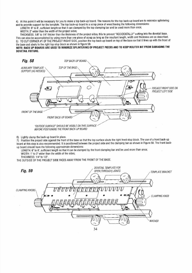
4) Atthis pointit will benecessaryoryou to makeatopback-upboard.Thereasonsor thetopback-upboardareto minimizesplintering
andto providesupportfor thetemplate.Thetopback-upboardis ascrappieceof woodhavingthefollowingdimensions:
LENGTH:6"to 8",sufficientlengthso that it canclampedbythe topclampingbarandbeusedmorethanonce;
WIDTH;2"wider thanthe widthof the projectsides;
THICKNESS:/8"to 1/4"thickerthanthethicknessof theprojectsides;thisto prevent"ACCIDENTALLY"uttinginto thedovetailbase,
Thiscanalsobeaccomplishedby usingmorethan onepieceof scrapas longasthe resultantength,widthandthicknessareasdescribed.
5) TOCUTCORNER10F THEPROJECTIGHTSIDE,positionthetop back-upboardontopofthebasesothatitlinesopwiththe frontof
thebaseandabutstotheright topstopblockasshowninfigure58.
NOTE:BACKUPBOARDSREUSEDTOMINIMIZESPLINTERINGFPROJECTIECESANDTOKEEPROUTERBITFROMDAMAGINGHE
DOVETAILIXTURE,
Fig, 58 TOPBACK-UPOARD
\
AUXILIARYEMPLATE TOPOFTHEBASE\ _ .
SUPPORT(ASNEEDED) _ _ _ _\_ / _ "_','-._
// \ ....\ ,., v
'k ,J
FRONTOFTHEBASE (( _._ .- _ _,L ,
FRONTACK'UPBOARD __
"OUTSIDEURFACE'HOULDEVtSIBLENTHISSURFACE-
BEFOREOSITIONINGHEFRONTACK-UPOARD
6) Lightlyclamptheback-upboardin place,
7) Positionhe projectsideagainsthefront of thebasesothatthetop surfaceabutsthe rightfrontstopblock.Theuseof afrontback'up
boardat thisstepis alsorecommended.t is positionedbetweenheprojectsideandthe clampingbaras shownin Figure58.Thefront back-
upboardshouldhavethefollowingapproximatedimensions:
LENGTH:"to 8",sufficientengthsothatit canbeclampedbythefront clampingbarandbeusedmorethanonce;
WIDTH:1"to 2"widerthanthewidthof thesides;
THICKNESS:/4"to 1/2".
THEOUTSIDEOFTHEPROJECTIDEFACESAWAYFROMTHEFRONTOFTHEBASE.
TEMPLATEOR
Fig. 59 TEMPLATERACKET
CLAMPINGKNOBSI
j CLAMPINGKNOB
\
WASHER
34
8/18/2019 Craftsman Dovetail Jig L0807067
http://slidepdf.com/reader/full/craftsman-dovetail-jig-l0807067 35/48
Thewords "OUTSIDESURFACE"markedin(d) in theSection,GENERALREPARATIONS,houldhavebeenvisiblebeforehefront back-up
boardwasput in place.
8) Lineuptheworkpiecessothat the endof the projectsideandback-upboardsDineupasshownin Figure58.
9) Securelyclampthe projectsideandthe front back-upboardto the frontof thebase.
10)Secureiydampthetopback-upboardto the topof thebase.
11)Makesurethatthe partsremainlinedup.
12)Assemblehe DOVETAILEMPLATEOROPEN(THROUGH)OINTSo theDovetaiIFixtureso thatTHETEMPLATERACKETSIT
BETWEENHEWASHERSNDTHETEMPLATEUPPORTSs shownFigure59; it will benecessaryoloosentheclampingknobsat theends
of thebasetodothis•
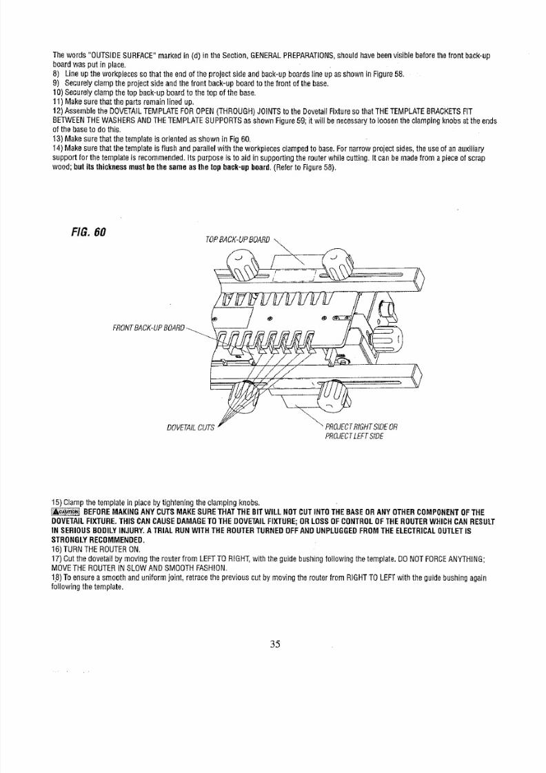
13)Makesurethatthe templates orientedasshownin Fig60.
14)Makesurethatthetemplate
is
flushandparailelwiththe workpiecesclampedo base.Fornarrowprojectsides,the useofanauxiliary
supportforthe templates recommended.tspurposeis toaid insupportinghe routerwhilecutting,Itcanbe madefroma pieceof scrap
wood;
butitsthicknessmustbethesameasthetopback-upboard.
RefertoFigure58).
FIG. 60
TOPB,4CK-UPOARD__
• _
0
FRONTACK-UPOARD
DOVETAILU RIGHTIDEOR
PROJECTEFTSIDE
<>
15)Ciampthetemplateinplaceby tighteninghe clampingknobs.
_ BEFOREMAKINGANYCUTSMAKESURETHATTHEBITWILLNOTCUTINTOTHEBASEORANYOTHERCOMPONENTFTHE
DOVETAILIXTURE.THISCANCAUSEDAMAGEOTHEDOVETAILIXTURE;ORLOSSOFCONTROLFTHEROUTERWHICHCANRESULT
IN SERIOUSBODILYNJURY.ATRIALRUNWITHTHEROUTERURNEDOFFANDUNPLUGGEDROMTHEELECTRICALUTLETS
STRONGLYECOMMENDED,
16)TURNTHEROUTERON.
17)CutthedovetaiIby movingthe routerfrom LEFTTORIGHT,withthe guidebushingoIIowiflgthetemplate.DONOTFORCENYTHING;
MOVETHEROUTERNSLOWANDSMOOTHFASHION.
18)Toensureasmoothanduniformjoint, retracehe previouscutby movingtherouterfromRIGHTTOLEFTwiththeguidebushingagain
followingthetemplate.
35
8/18/2019 Craftsman Dovetail Jig L0807067
http://slidepdf.com/reader/full/craftsman-dovetail-jig-l0807067 36/48
NEVERLIFTTHEROUTERUPWARDSWHENTHEROUTERSONANDTHEROUTER
BIT
ROTATINGRWHENTHEGUIDE
BUSHINGSNEARTOORTOUCHINGHETEMPLATE.HISCANCAUSEDAMAGEOTHEDOVETAILIXTURE;ORLOSSOFCONTROLOF
THEROUTERWHICHCANRESULTN SERIOUSBODILYNJURY.
19)Afterthecut hasbeenmade,he workpiecesshouldlook likethoseillustratedn Figure60.
20)Removeheworkpieceandback-upboardsfromthe DovetailFixture.
21) Theback-upboardscanbereused f thecut portionsof boardsarecut off.AFTERBEINGREUSEDUNTILTHEYNOLONGERSERVE
THEIRNTENDEDUNCTION,EWBACK-UPBOARDSMUSTBEMADE.
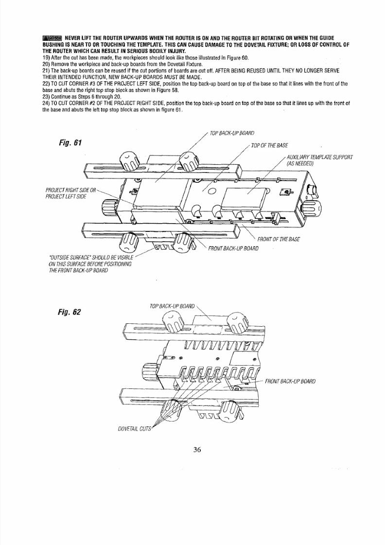
22)TOCUTCORNER3OFTHEPROJECTEFTSIDE,positionthe topback-upboardontop of the basesothat it lineswiththe frontof the
baseandabutsthe righttopstopblockasshowninFigure58.
23)ContinueasSteps6through20.
24)TOCUTCORNER2 OFTHEPROJECTIGHTSIDE,positionthe top back-upboardontopof thebaseso thatit linesupwith thefront of
thebaseandabutsthe lefttop stopblockasshownin figure61.
TOPBACK-UPBOARD
Fig. 61 / / TOPFTHEASE .
f / AU, ,AR TE , T SBR
.....=. ,./ ., V
,RO,
DT ,ETSIDE....
//.-.
--.-./ 7/ --"
t
%
"OUTSIDEURFACESHOULDEVISIBLE
ONTHtSSURFACEEFOREOSITtONING
THEFRONTACK-UPOARD
Fig. 62
TOPBACK-UPOARD,
FRONTACK-UPOARD
DOVETAIL
36
8/18/2019 Craftsman Dovetail Jig L0807067
http://slidepdf.com/reader/full/craftsman-dovetail-jig-l0807067 37/48
25) Lightly clamp the back-up board in place.
26) Posit ion the project side against the front of the baseso that the top surface abuts the left front stop bIock,The useof a front back-up
board atthis step is also recommended. It is
positioned
between the project sideand the cIamping bar asshown in Figure61.The front
back-up board is described in Step 7 above.
27) Continueas in Steps 8 through 19 above.
28) After the cuts havebeen made,the workpieces should look like those illustrated in Figure62.
29) Removethe workpiece andthe back-up boards from the Dovetail Fixture.NOTE:THE BACK-UP BOARDSAREREUSABLE.
30) TOCUTCORNER
#4
OFTHEPROJECTLEFTSIDE, position the top back-up board on top of the baseso that it fines up with the front of
the baseand abuts
the
left top stop block asshown is Figure6 .
31) Continueas Steps27 through
32
above.
32) Atthis stage the project sides should look like those iIfustrated in Figure56,
THEFOLLOWINGDESCRIBESTHEPROCEDURETO BEFOLLOWEDFORCUTTINGTHEPROJECT
FRONTANDBACK:
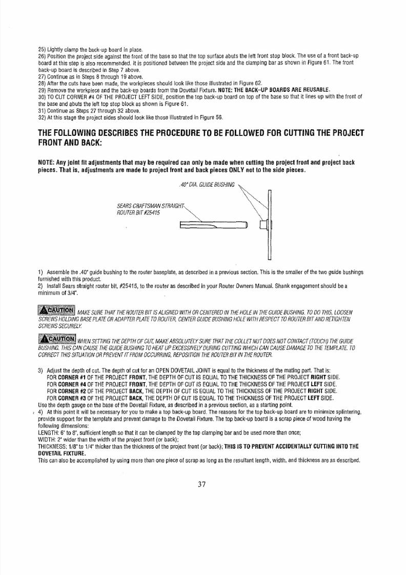
NOTE:Anyjoint fit adjustmentsthatmay be required canonly bemadewhen cuttingthe projectfrontand projectback
pieces. That is, adjustmentsare madeto projectfront endbackpiecesONLYnotto the side pieces,
.40"DIA,GUIDEUSHING
SEARSRAFTSMANTRAIGHT\ _
ROUTERIT#25415 _
1) Assemblehe.40"guidebushingto the routerbaseplate,asdescribedn aprevioussection.Thisis thesmallerof thetwo guidebushings
furnishedwiththis product,
2) InstallSearsstraightrouterbit,#25415,to therouterasdescribedinyourRouterOwnersManualShankengagementhouldbea
minimumof 3/4".
_i MAKESURETHATTHEROUTERITSALIGNEDWITHORCENTEREDNTHEHOLENTHEGUIDEUSHfNG.ODOTHIS,OOSEN
SCREWSOLDINGASEPLATEORADAPTERLATEOROUTER,ENTERUIDEUSHINGOLEWITHRESPECTOROUTERfTANDRETIGHTEN
SCREWSECURELY
_ WHENETTINGHEDEPTHOFCUT,MAKEABSOLTELYURETHATTHECOLLETUTDOESNOTCONTACTTOUCH)HEGUIDE
BUSHING.HISCANCAUSEHEGUIDEUSHtNGOHEATUPEXCESSIVELYURINGUTTINGWHICHCANCAUSEAMAGEOTHETEMPLATE.O
CORRECTHfSSITUATIONRPREVENTTFROMOCCURRING,EPOSITtONHEROUTERITtNTHEROUTER.
3) Adjustthedepthof cut.Thedepthof cutfor anOPENDOVETAILOINTsequaltothethicknessof the matingpart,That
is:
FORCORNER1OFTHEPROJECTRONT,THEDEPTHOFCUTIS EQUALTOTHETHICKNESSFTHEPROJECT IGHTSIDE.
FORCORNER40FTHE PROJECTRONT,THEDEPTHOFCUTIS EQUALTOTHETHICKNESSOFTHEPROJECTEFTSIDE.
FORCORNER2 OFTHEPROJECTACK,THEDEPTHOFCUTIS EQUALTOTHETHICKNESSOFTHEPROJECT IGHTSIDE.
FOR
CORNER
3 OFTHEPROJECTACK,THEDEPTHOFCUTIS EQUALTOTHETHICKNESSOFTHEPROJECTEFTSIDE,
UsethedepthgaugeonthebaseoftheDovetailFixture,as describedn aprevioussection,asa startingpoint.
, 4) Atthisp_intitwi__benecess_ryf_ry_ut_makeat_pb_ck_upb_ard_Thereas_nsf_rthet_pback_upb_ard_ret_minimizesp_intering_
providesupportfor thetemplateandpreventdamageothe DovetailFixlure,Thetop back-upboardis ascrappieceofwood havingthe
followingdimensions:
LENGTH:"to 8",sufficientengthso thatit canbeclampedbythe top clampingbarandbe usedmorethanonce;
WIDTH:2"widerthanthewidthof theprojectfront(or back);
THICKNESS:/8"to 1/# thickerthanthethicknessof the projectfront (orback);THISIS TOPREVENTCCIDENTALLYUTI'INGNTOTHE
DOVETAILIXTURE.
Thiscanalsobeaccomplishedby usingmorethanonepieceof scrapas longasthe resultantength,width,andthicknessareasdescribed,
3?
8/18/2019 Craftsman Dovetail Jig L0807067
http://slidepdf.com/reader/full/craftsman-dovetail-jig-l0807067 38/48
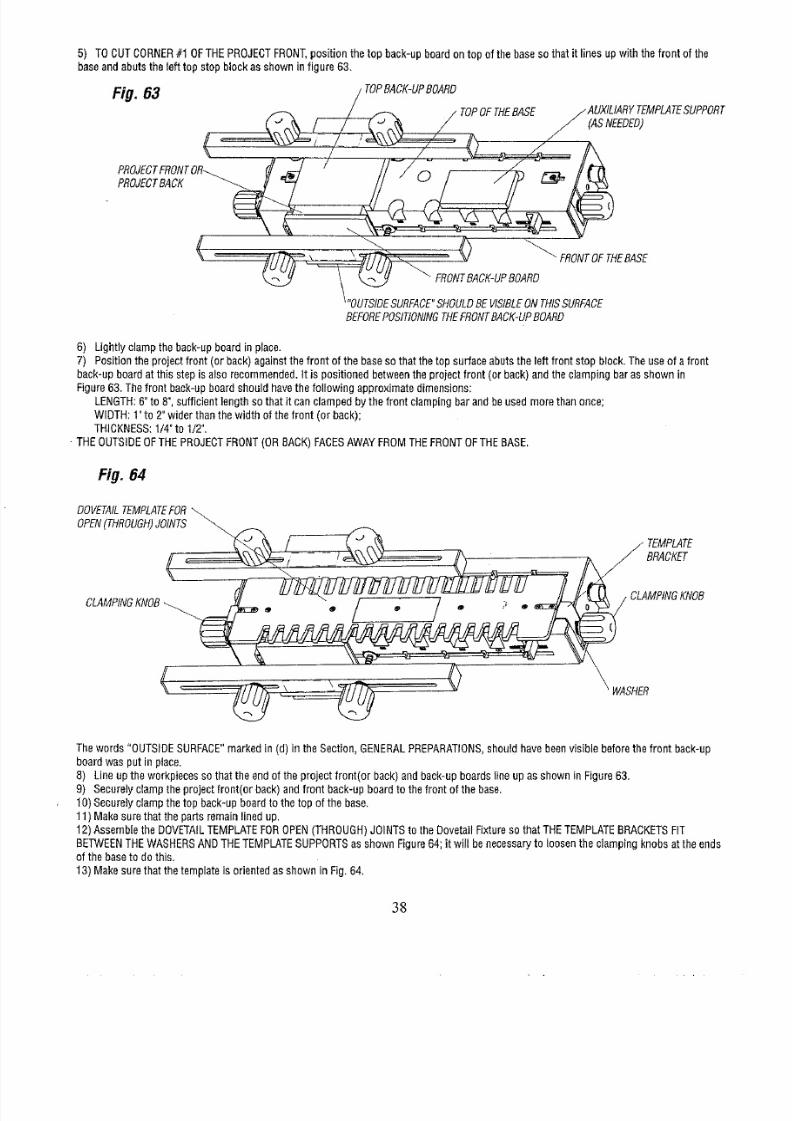
5) TOCUTCORNER1 OFTHEPROJECTRONT,ositionthe topback-upboardontop of thebasesothat it linesupwiththe frontof the
baseandabutsthe lefttopstopblockasshowninfigure 63.
Fig.83 / TOPACKPOARD
_ / TOPOFTHEBASE /'AUXILIARY TEMPLATEUPPORT
/CASNEEOEO
( .... /
PROJECTACK _ __
<>
FRONTOFTNE
BEFOREOSITIONINGHEFRONTACK-UPOARD
6) Lightlyclamptheback-upboardin place.
7) Positiontheprojectfront(or back)againsthe frontof thebaseso thatthetopsurfaceabutsthe leftfrontstop bIock.Theuseof a front
back-upboardat thisstepisaIso recommended.t is positionedbetweenhe projectfront(or back)andthedampingbarasshownin
Figure63.Thefront back-upboardshouldhavethefollowingapproximatedimensions:
LENGTH:"to 8",sufficientlengthsothat it canclampedbythe frontclampingbarandbeusedmorethanonce;
WIDTH:1"to 2"widerthanthewJdthof thefront (orback);
THICKNESS:/4"to 1/2",
-THEOUTSIDEOFTHEPROJECTRONTORBACK)FACESAWAYFROMTHEFRONTOFTHEBASE,
Fig. 84
___( CLATEMPMTE
BRACKET
MPINGKNOB
_ WASHER
Thewords"OUTSIDESURFACE"arkedin (d) in theSection,GENERALREPARATIONS,houldhavebeenvisiblebeforethefront back-up
boardwasput inplace.
8) Lineuptheworkpiecessothattheendof theprojectfront(orback)andback-upboardslineupasshowninFigure63.
9) Securelyclamptheprojectfront(orback)andfrontback-upboardto thefrontof thebase.
10)Securelyclampthetop back-upboardto the topof thebase,
11)Makesurethatthepartsremainlinedup.
12)AssembleheDOVETAILEMPLATEOROPENTHROUGH)OINTSo theDovetailFixtureso that THETEMPLATERACKETSIT
BETWEENHEWASHERSNDTHETEMPLATEUPPORTSsshownFigure64;it will benecessaryo loosentheclampingknobsat theends
of thebaseto dothis.
13)Makesurethatthe templates orientedasshownin Fig,64,
38
8/18/2019 Craftsman Dovetail Jig L0807067
http://slidepdf.com/reader/full/craftsman-dovetail-jig-l0807067 39/48
Fig.65
TOPACK-UPOARD
DOVETAIL
DRAWERACK
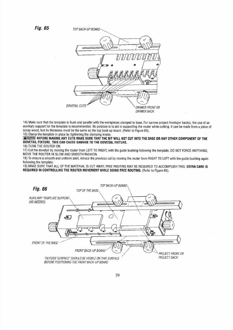
14)Makesurethatthetemplates flushandparallelwiththeworkptecesdampedto base,Fornarrowprojectfronts(orbacks),he useof an
auxiliarysupportfor the templates recommended.ts purposes toaidin supportingherouterwhilecutting,it canbemadefroma pieceof
scrapwood;butits thicknessmustbethe sameasthetop back-upboard,(Refero Figure63).
15)Clampthetemplaten placebytighteninghe clampingknobs.
BEFOREMAKINGANYCUTSMAKESURETHATTHEBITWILLNOTCUTINT0THEBASEORANYOTHERCOMPONENTFTHE
DOVETAILIXTURE.THISCANCAUSEDAMAGEOTHEDOVETAILIXTURE,
16)TURNTHEROUTERON.
17)Cutthedovetailby movingtherouterfrom LEFFTORIGHT,with the guidebushingfollowingthe template.DONOTFORCEANYTHING;
MOVETHEROUTERNSLOWANDSMOOTHFASHION.
18)Toensureasmoothanduniformjoint, retracehe previouscutby movingtherouterfrom RIGHTTOLEFTwiththe guidebushingagain
followingthetemplate.
19) MAKESURETHATALL OFTHEMATERIALSCUTAWAY;FREEROUTINGMAYBEREQUIREDOACCOMPLISHHIS.EXTRACARE18
REQUIRED
N
CONTROLLINGHEROUTERMOVEMENTWHILEDOINGFREEROUTING,
Refero Figure65).
Fig. 66
TOPOFTHEBAsE_PBACK-UPBOARD_/_._
A.XILIARY .PLATEU PORT, \
:ASEEDED , - i -: 0
FRONTOETHEBASE_ / ' \
/ v -_PROJECTFRONTR
/
"OUTSIDEURFACE"HOULDEVISIBLENTHISSURFACE PROJECTACK
BEFOREOSITIONINGHEFRONTACK-UPOARD
39

8/18/2019 Craftsman Dovetail Jig L0807067
http://slidepdf.com/reader/full/craftsman-dovetail-jig-l0807067 40/48
NEVERLIFT THEROUTERUPWARDSWHENTHE ROUTERS ONANDTHEROUTERBITROTATINGORWHEN THEGUIDEBUSH-
ING iS
NEAR
TO
OR
TOUCHING
THE
TEMPLATE.
20) After the cut bas beenmade, the workpiecesshould look like thoseillustrated in Figure65,
21) Removethe workpiece and back-up boards from the Dovetail Fixture.
22) The back-up boardscan bereused if the cut portions of boardsare cut off.AFTERBEINGREUSEDUNTIL THEY NOLONGERSERVE
THEIR INTENDEDFUNCTION,NEW BACK-UPBOARDSMUST BE MADE,
23)TO CUTCORNER#3 OFTHEPROJECTBACK,position the top back-up board on top of the baseso that it lines with the front of the base
and abuts the left top stop block asshown in Figure 63.
24) Continue as Steps 6 through 24.
25) TO CUT CORNER#4 OFTHEPROJECTFRONT,position the top back-up beard on top of the baseso that it lines up with the front of the
baseand abuts the right top stop block asshown infigure 66.
26) Lightly clamp the back-up board in place,
27) Position the project front (or back) againstthe front of the baseso thatthe top surface abuts the right front stop block. The use of a fronl
back-upboardal this step is also recommended,It is positioned betweenthe drawerfront (or back) and the clamping bar asshown in
Figure66. The front back-up board is described in Step7 above,
28) Continue as in Steps 8 through 20 above.
29) After the cuts havemade,the workpieces should Iook like those illustrated in Figure65.
30) Removethe workpiece and the back-up boards from the Dovetail Fixture. NOTE:THEBACK-UPBOARDSAREREUSABLE.
31) TO CUT CORNER#2 OFTHE PROJECTBACK,position the top back-up board on top of the baseso that it lines up with the front of the
baseandabuts the right top stop block as shown is Figure 66.
32) Continue as Steps 28 through 32 above.
33) The finished project front, back,and sides should look like those illustrated in Figure56.
34) Checkhow the workpieces fit together_Some adjustments may be necessary. Referto the Section, MAKINGADJUSTMENTSFOROPEN
(THROUGH)FLUSHJOINTS
Your project is now readyto be gIuedtogether,
Removethe pencil markings by light sanding orwith a soft eraserafter the parts havebeenglued together.
TROUBLESHOOTING:
*
If
thejoint
is too loose:Thisadjustmentcanonlybemadewhencuttingeitherthe front or
the
back(pinpieces).Loosentheclamping
knobsholdingthetemplatebracketsandmovethetemplateOUTWARDyturninghe cam handles,Continueadjustinguntildesiredjoint
fit is attained.Retightenhe clampingknobs.
= tt thejoint is tootight: Thisadjustmentoo canonlybemadewhencuttingeitherthefront ortheback(pin pieces).Loosentheclamping
knobsholdingthetemplatebracketsandmovethetemplateINWARDbyturningthecam handles.Continueadjustingunti desiredoint fit
is attained.Retightenheclampingknobs.
• If the joint
is
too
shallow:
RefertoFigure67,INCREASEhe depthofcutof therouterbit.Thisadjustmentcanbe madewhencuttingthe
front,
the
back,(pin pieces)andthesides(taiI
pieces),
o If t he joint
is
toodeep:Referto Figure68.DECREASEhe depthof cut of therouterbit,Thisadjustmentoocanbemadewhencutting
thefront, theback,(pinpieces)andthesides(tailpieces).
, If the jointisnot uniformlyspacedromtop surfaceof drawer:Referto Figure69.(SeetheSection"ALIGNMENTOFTHETEMPLATES".)
Withthe templateclampedo the base,loosenthefourscrewssecuringhe templateo the templatebrackets,andmovethetemplate
slightlyto theleft. Tightenhe fourscrewsandmakea
trial
cut.If movingthetemplateto the
left
did notcorrectthe condition,butmadet
worse,loosenthe screwsandmovethetemplateto the right aemalIamount.Makesurethetemp[ateremainsparallelto the front of the
dovetailbase.Tightenthefour screwsandmakea trial cut, Continuemovingthetemplateto the right untgthe conditionis completely
corrected.PROPERALIGNMENTOFTHETEMPLATESOTHETEMPLATERACKETSSCRITICALFORJOINTUNIFORMITY.NCETHiS
iSACCOMPLISHEDORRECTLY,TSHOULDNOTNEEDADJUSTMENTSGAIN.MAKESURETOSECURELYIGHTENTHEFOUR
SCREWS.AFTERTHETEMPLATESAVEBEENCORRECTLYEALIGNED,HEYSHOULDREQUIRENOFURTHERDJUSTMENTSF
THEYAREHANDLEDWITHCARE.
4O
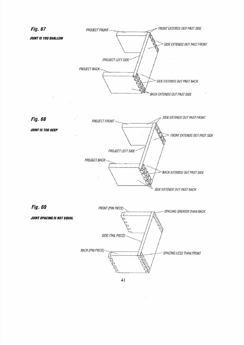
8/18/2019 Craftsman Dovetail Jig L0807067
http://slidepdf.com/reader/full/craftsman-dovetail-jig-l0807067 41/48
Fig. 67
JOINTSTOOSHALLOW
PROJECTRONT__ __.
PROJECTEFTSlOE
PROJECTACI__
/
FRONTXTENDSUTPASTSIDE
_ SIDEEXTENDSUTPASTFRONT
Fi#.68
SIDEEXTENDSUTPASTFRONT
JOINTIS TOODEEP
_ FRONTXTENDSUTPASTSIDE
SIDEEXTENDSOUTPASTBACK
Fig. 69
JOINTSPACINGSNOTEQUAL
FRONTPINPIECE)
SIDETAILPIECE)
BAOK(PINPIECE)
_ SPACtNGREATERHANBACK
SPACINGESSTHANFRONT
41

8/18/2019 Craftsman Dovetail Jig L0807067
http://slidepdf.com/reader/full/craftsman-dovetail-jig-l0807067 42/48
PARTS LIST for #171.25450 INDUSTRIAL DOVETAIL FIXTURE
KEY OTY PART NO.
I I 29LD-879
2 I 29LD-880
3 I 29LD-8BI
4 I 29LD-882
5 I 29LD-883
6 2 29LD-884
7 2 29LD-885
8 2 29LD-886
9 4 29LD-887
I 0 I 29LD-888
I 4 29LD-889
12 6 29LD-890
13 2 29LD-891
14 I 29LD-892
15 4 29LD-895
16 2 29LD-896
17 I 29LD-899
8 I 29LD-900
I9 4
29LD-901
20 I 45A-350
21 I 45A-351
22 I 45A-352
23 I 45A-353
I 49LD-50
I NONE
24 4 29L-469-13
25 8 29L-469-14
26 I0 29L-469-15
27 2 29LD-841 -2
28 2 29LD-841 -3
29 3 29LD-841-4
30
I
29L-684-6
31 3 29L-684-7
32 2 29A-310-15
33 2 29A-310-16
34 2 29A-310-17
35 4 29A-242-12
36 2 29A-242-I3
37 9 29A-306-37
38 8 29A-306-40
39 4 29LD-930
40 4 29LD-969
4 4 29LCN-IO05
DESCRIPTION
DOVETAIL BASE
DOVETAIL TEMPLATE HALF BLIND JOINT
DOVETAIL TEMPLATE OPEN (THROUGH) JOINT
TEMPLATE SUPPORT (RIGHT SIDE)
TEMPLATE SUPPORT (LEFT SIDE)
CAM HANDLE
FRONT STOP BLOCK
TOP STOP BLOCK
CLAMPING BAR END CAP
RETAINER
BOLT SUPPORT
ICLAMPING KNOB
CLAMPING BAR
PIVOT SHAFT
TEMPLATE BRACKET
TEMPLATE STIFFENER
GUIDE BUSHING ASSEMBLY (.40" DIAMETER)
GUIDE BUSHING ASSEMBLY (I12" DIAMETER)
COMPRESSION SPRING
PRODUCT LABEL (CLAMPING BAR)
LABEL (TEMPLATE-BL IND)
LABEL (TEMPLATE-OPEN
WARNING LABEL (CLAMPING BAR)
INSTRUCTION MANUAL
BAGGED FASTENERS-CONSISTING OF :
#10-32 X 518" Ig. PANHEAD MACHINE SCREW
#I0-32 X 318" Ig. PANHEAD MACHINE SCREW
#8-36 X 3/16" Ig. PANHEAD MACHINE SCREW
#I0-32 X 518" Ig. FLAT HEAD MACHINE SCREW
#I0-32 X 7/8" Ig. FLAT HEAD MACHINE SCREW
_10-32 X 3/8" Ig. FLAT HEAD MACHINE SCREW
#IO-16 X I12" Ig. PANHEAD TAPPING SCREW
#I0-16 X I" 19. PANHEAD TAPPING SCREW
5/16-18 X 4-1/2" Ig. ROUND HEAD SQUARE NECK BOLT
5/16-18 X 3-I/2" Ig. ROUND HEAD SQUARE NECK BOLT
,5/16-18
X 2" Ig. ROUND H EAD SQUARE NECK BOLT
#I0-32 HEX MACHINE SCREWNUT
5ll6-18 HEX MACHINE SCREWNUT
3/64"1.D. X 9/I6"0,D. X 3/64"fhick WASHER
1/32"I.D. X 7/8"0,D. X 1/I6"thick WASHER
1/32"I,D. X 7/8"0,D. THIN NYLON WASHER
5/16"I,D, X 7/8"0.D. THICK NYLON WASHER
NYLON SPRING
RETAINER
42
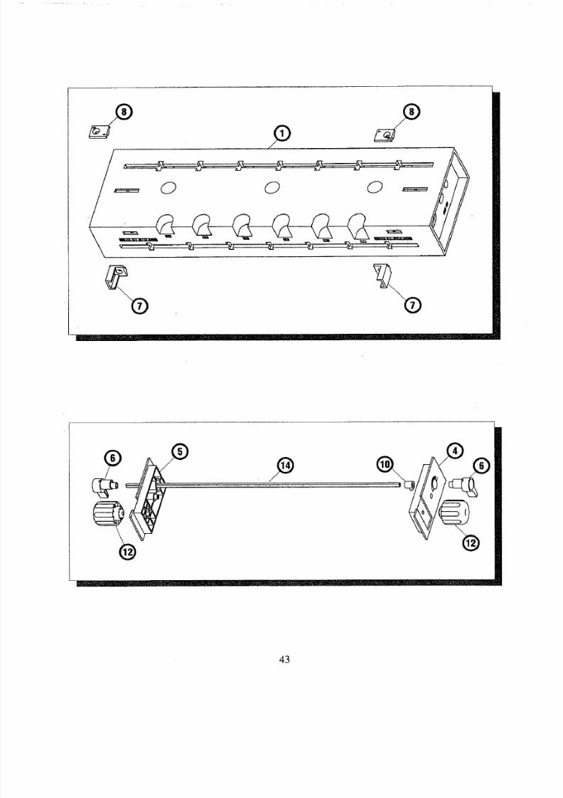
8/18/2019 Craftsman Dovetail Jig L0807067
http://slidepdf.com/reader/full/craftsman-dovetail-jig-l0807067 43/48
43
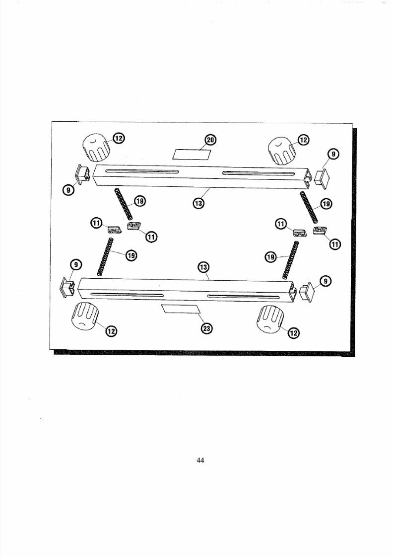
8/18/2019 Craftsman Dovetail Jig L0807067
http://slidepdf.com/reader/full/craftsman-dovetail-jig-l0807067 44/48
44
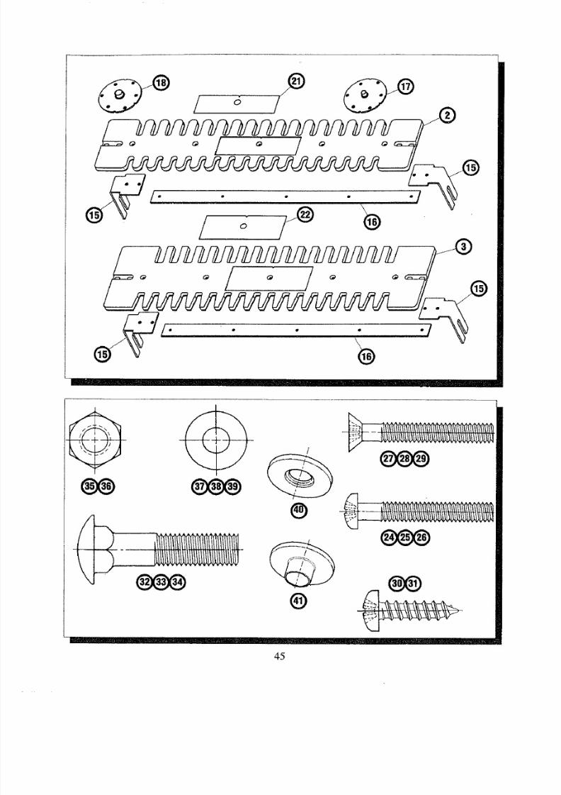
8/18/2019 Craftsman Dovetail Jig L0807067
http://slidepdf.com/reader/full/craftsman-dovetail-jig-l0807067 45/48
1
/ o /_
®
"/
L
. .
®
®
@
45

8/18/2019 Craftsman Dovetail Jig L0807067
http://slidepdf.com/reader/full/craftsman-dovetail-jig-l0807067 46/48
Notes
46

8/18/2019 Craftsman Dovetail Jig L0807067
http://slidepdf.com/reader/full/craftsman-dovetail-jig-l0807067 47/48
Notes
47

8/18/2019 Craftsman Dovetail Jig L0807067
http://slidepdf.com/reader/full/craftsman-dovetail-jig-l0807067 48/48
IIII
I IIit
II
49LD-60
MANUAL
Whencorresponding,alwaysgivethe following
informationas showninthe list.
1. The PARTNUMBER