cracks and crack control in concrete structures - pci · cracks and crack control in concrete...
TRANSCRIPT

Special Report
Cracks and Crack Controlin Concrete Structures
Fritz LeonhardtProfessor EmeritusDr.-Ing. Dr.-Ing. h.c. mull.Consulting EngineerStuttgart, FRG
T he material presented in this paper isbased on more than 30 years of re-
search, observations and experienceconcerning causes, control, and conse-quences of cracking in concrete struc-tures. This extensive background washelpful in the preparation of this paperwhich deals with questions of concretecracking.
The presence of cracking does notnecessarily indicate deficiency instrength or serviceability of concretestructures. While currently available de-sign code provisions lead to reasonablecontrol of cracking, additional controlcan be achieved by understanding thebasic causes and mechanisms of crack-
Note: This paper is a revised and updated version ofan article originally published in the Proceedings ofthe International Association for Bridge and Struc-tural Engineering (1ABSE), Zurich, Switzerland,1987, p. 109.
ing in concrete structures. In this paper,causes of concrete cracking are dis-cussed, including tensile strength ofconcrete, temperature, shrinkage andcreep effects. Recommended crackwidths are presented along with designmethods for sizing reinforcement tocontrol crack widths.
CAUSES OF CRACKINGConcrete can crack due to a number of
causes. Some of the most significantcauses are discussed in detail.
Tensile Strength of ConcreteThe tensile strength of concrete is a
widely scattering quantity. Cracking oc-curs when tensile stresses exceed thetensile strength of concrete. Therefore,to control concrete cracking, the tensilestrength of concrete is of primary im-
124

portance. Laboratory test data con-ducted by H. Busch were analyzedstatistically. As presented in Ref. 1, thisanalysis furnished the following re-lationships for the mean direct tensilestrength, f tm , related to the 28-daycompressive cylinder strength f,' of con-crete:
fcm = 2.1 (fc)z /3 (psi)
fi'm = 0.34 (ff)2"'(N/mm2)
The statistical analysis indicated thatthe coefficient in this equation can bemodified to 1.4 (0.22) and 2.7 (0.45) toobtain the 5 and the 95 percentiles, re-spectively, of the tensile strength, fI.The tensile strength of concrete isslightly higher in flexure. However, it isrecommended that values for direct ten-sion be used in practice. Concretecracks when the tensile strain, € °t , ex-ceeds 0.010 to 0.012 percent. Thislimiting tensile strain is essentially in-dependent of concrete strength.
The 5 percentile of the tensilestrength, f, should be used in design tolocate areas in the structure that arelikely to crack by comparing calculatedstresses with the expected concretestrength. The 95 percentile, f 5 , shouldbe used to obtain conservative values forrestraint forces that might occur beforethe concrete cracks. These restraintforces are used to calculate the amountof reinforcement needed for crack widthcontrol.
Causes of Cracking DuringConcrete Hardening
Concrete cracking can develop duringthe first days after placing and beforeany loads are applied to the structure.Stresses develop due to differentialtemperatures within the concrete.Cracking occurs when these stresses ex-ceed the developing tensile strength, f;,of the concrete as indicated in Figs. 1and 2. Differential temperatures aremainly due to the heat of hydration of
SynopsisSimple design rules are presented
to control cracking in concrete struc-tures. Causes of cracking and its ef-fect on serviceability and durability arediscussed. The paper is primarily ap-plicable to large structures such asbridges. However, general conceptspresented are applicable to any con-crete structure. Prestressing forcesare considered. A numerical exampleshowing application of the methodand use of simple design charts is in-cluded.
cement during concrete hardening. Thiseffect is usually neglected except inmassive structures as indicated in Ref. 2.However, depending on cement contentand type of cement, the temperaturewithin concrete members with dimen-sions of 12 to 36 in. (30 to 91 cm) canincrease approximately 36°F to 108°F(20°C to 60°C) during the first 2 daysafter casting.
If concrete members are allowed tocool quickly, tensile stresses may reachvalues higher than the developing ten-sile strength of the concrete. Even if thisprocess results only in microcracking,the effective tensile strength of thehardened concrete is reduced. How-ever, very often wide cracks appeareven when reinforcement is provided.In addition, the reinforcement may notbe fully effective since bond strength isalso developing and is yet too low. It isnecessary to minimize such early cracksby keeping temperature differentialswithin the concrete as low as possible.This can be done by one or more of thefollowing measures:
1. Choice of cement — A cement withlow initial heat of hydration should beselected. Table 1 shows that there is asignificant variation in heat develop-
PCI JOURNAUJuly-August 1988 125

b concrete
compression
GT+ +G = OT a T Ec
tension
Internal stressesin equilibrium
Fig. 1. Temperature distribution due to heat of hydration andinternal stresses caused by outside cooling in a free standingconcrete block.
ment among different types of cements.The cement content of concrete shouldbe kept as low as possible by goodgrading of the aggregates. Heat de-velopment can also be reduced by ad-ding fly ash or using slag furnace ce-ment.
2. Curing — Evaporation of watermust be prevented by using curingcompounds or by covering the concretewith a membrane. Rapid evaporationcan lead to plastic shrinkage cracking.
3. Curing by thermal insulation -Rapid cooling of the surface must beprevented. The degree of thermal insu-lation depends not only on the climate,but also on the thickness of the concretemember and on the type of cement used.Spraying cold water on warm young
concrete, as it was done years ago, is notrecommended.
4. Precooling — This is a necessity forlarge massive concrete structures suchas dams. For more usual structures, inwhich shortening after cooling can takeplace without creating significant re-straint forces, precooling is expensiveand unnecessary. In this case, thermalinsulation is preferable and it also hasthe benefit of accelerating concretestrength development. An exceptionmay be made in very hot climates sinceprecooling can keep concrete workablefor a longer period of time.
Often shrinkage is considered as acause of early cracking. However, this isnot true under normal climatic condi-tions. Shrinkage needs time to produce a
126

Table 1: Heat of hydration of various types ofcements.*
Type ofcementt
Heat of hydration (Btu/1b)
1 day 3 days 7 days 28 days
I 92 144 157 167
II 76 115 135 148
III 139 184 194 205
IV 50 81 94 117
V 58 88 101 124
*Data obtained from Concrete Manual, U.S. Bureau ofReclamation, 1975, pp. 45-46.t Federal Specifications SS-C-192G, including InterimAmendment 2, classified the live types according to usage asfollows: Type I for use in general concrete construction whenTypes 11, 111, 1V, and V are not required; Type 11 for use inconstruction exposed to moderate sulfate attack; Type III for usewhen high early strength is required; Type IV for use when lowheat of hydration is required; and Type V for use when high sulfateresistance is required.Note: 1.0 Btu/Ib = 2.32 J/g.
shortening as high as the tensile rupturestrain. Only in very hot and dry airshrinkage can cause early cracks inyoung concrete, if measures againstevaporation are not applied.
Causes of Cracking AfterConcrete Hardening
Tensile stresses due to dead and liveloads cause cracking. Normal rein-
cracking due to restraint
tensile strength fit
Internal Stress
5 10 15 20 h
Concrete hardening time, hours
Fig. 2. Development of the tensile strength and stresses due to nonlineartemperature distribution within the concrete.
PCI JOURNAL/July-August 1988 127

Deformed Shape considering Upper Faceof Beam Warmer Than Bottom Face andassuming beam freed from interior Supports^
I I I
I MDTMoment Diagram
VAT
Shear Diagram
Fig. 3. Forces in a concrete beam due to a temperature rise OT atthe upper face of the beam and external restraint provided byinterior supports.
forcement or prestressing should be de-signed to provide required strength andkeep crack widths within permissiblelimits. Tensile stresses due to serviceloads can be controlled by prestressing.The degree of prestressing can be cho-sen based on structural or economicconsiderations. Normally, partial pre-stressing leads to better serviceabilitythan full prestressing.
Cracks can also be initiated by ten-sile stresses due to restrained defor-mations from temperature variations orfrom shrinkage and creep of concrete.Imposed deformations such as differ-ential settlement between foundationscan also cause cracks.
There are two types of restraint whichcause stress in concrete members,namely, internal restraint as shown inFig. 1, and external restraint in indeter-minate structures, as shown in Fig. 3.Restrained deformations caused crack-ing in concrete bridges and it wasprimarily due to temperature differ-ences produced by heating under thesun and cooling during the night. Ex-
treme temperatures that occur at 20 to50-year intervals must be considered. Asindicated in Refs. 3, 4, 5 and 6, temper-atures in bridge structures were mea-sured in several countries. Recently, theU.S. Transportation Research Boardpublished in Ref. 7 temperature data forbridge design.
Temperature differentials should beconsidered along with recommendedmean temperatures, Tm, used for cal-culating maximum and minimumchanges in the lengths of structuralmembers. In Central Europe values forT. are specified for concrete bridges asvarying from +68°F to –22° (+20°C to–30°C).
The temperature distribution over abeam cross section can be subdividedinto three parts as shown in Fig. 4. Theconstant part, 0 T,, causes axial forces ifoverall length changes are restrained.The linear part, AT,, causes restraintforces, M AT and V AT, in indeterminatestructures as shown in Fig. 3 for a threespan continuous beam. The nonlinearpart, AT3i causes stresses, which are in
128

Table 2. Recommended cross section temperaturedifferentials for bridge design in Europe.
Box girder T-beamsType ofcross section Mari- Conti- Mari- Conti-and exposure time nental time nental
Top ofcross sectionwarmer thanbottom (°F) 18 27 14.4 21.6
Bottom ofcross sectionwarmer thantop(F) 9 14.4 7.2 10.8
Note: 1.0 A N' _ (9/5) A°C.
equilibrium over the cross section andproduce no action forces. Thesestresses, which also exist in staticallydeterminate structures, can be calcu-lated by imposing equilibrium condi-tions and considering that:
JcT = AT3aTEc
where a T is equal to 6 x 10 -6 /0 F(10-5/° C), the coefficient of thermal ex-
pansion for concrete. Cooling causestensile stresses in areas near extremitiesof the section.
For bridges in Europe, the AT valuesgiven in Table 2 are recommended. Inaddition to temperature, restrained con-crete creep and shrinkage can causestresses. Shrinkage often leads to cracksbetween connected members of signifi-cantly different sizes. Stress due to re-strained creep and shrinkage can be cal-
rig. 4. uivision of temperature aiagram into its constant, unear ana noniinear parts.
PCI JOURNAL/July-August 1988 129
plan A-A
i i h i i
H
G
compressive Gdue to DL+w LL+ P
'—_–'-- cracks due toAT, AS and ACr
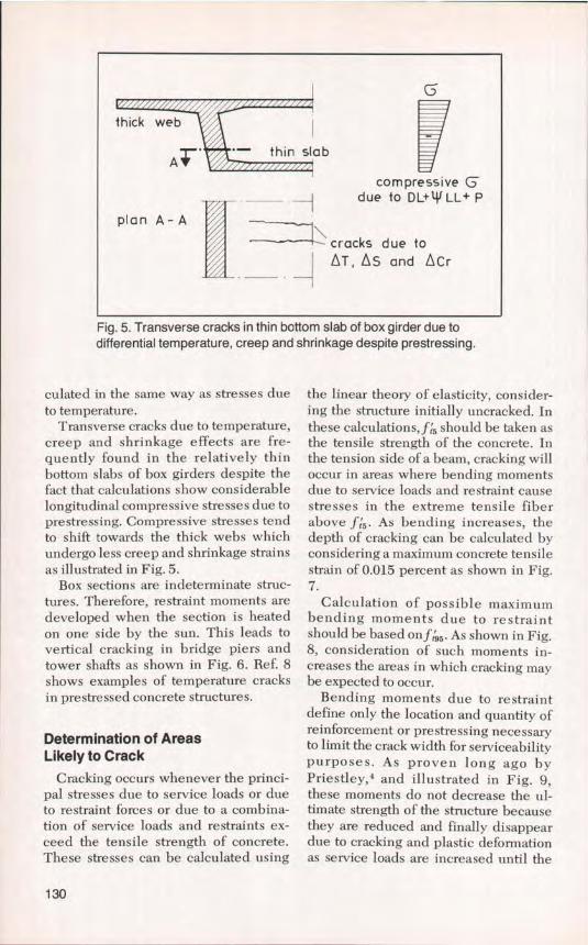
Fig. 5. Transverse cracks in thin bottom slab of box girder due todifferential temperature, creep and shrinkage despite prestressing.
culated in the same way as stresses dueto temperature.
Transverse cracks due to temperature,creep and shrinkage effects are fre-quently found in the relatively thinbottom slabs of box girders despite thefact that calculations show considerablelongitudinal compressive stresses due toprestressing. Compressive stresses tendto shift towards the thick webs whichundergo less creep and shrinkage strainsas illustrated in Fig. 5.
Box sections are indeterminate struc-tures. Therefore, restraint moments aredeveloped when the section is heatedon one side by the sun. This leads tovertical cracking in bridge piers andtower shafts as shown in Fig. 6. Ref. 8shows examples of temperature cracksin prestressed concrete structures.
Determination of AreasLikely to Crack
Cracking occurs whenever the princi-pal stresses due to service loads or dueto restraint forces or due to a combina-tion of service loads and restraints ex-ceed the tensile strength of concrete.These stresses can be calculated using
the linear theory of elasticity, consider-ing the structure initially uncracked. Inthese calculations, f,s should be taken asthe tensile strength of the concrete. Inthe tension side of a beam, cracking willoccur in areas where bending momentsdue to service loads and restraint causestresses in the extreme tensile fiberabove f15 . As bending increases, thedepth of cracking can be calculated byconsidering a maximum concrete tensilestrain of 0.015 percent as shown in Fig.7.
Calculation of possible maximumbending moments due to restraintshould be based on f 5 . As shown in Fig.8, consideration of such moments in-creases the areas in which cracking maybe expected to occur.
Bending moments due to restraintdefine only the location and quantity ofreinforcement or prestressing necessaryto limit the crack width for serviceabilitypurposes. As proven long ago byPriestley, and illustrated in Fig. 9,these moments do not decrease the ul-timate strength of the structure becausethey are reduced and finally disappeardue to cracking and plastic deformationas service loads are increased until the
130

deflection line
vertical cracks
-MAT
II
+ +MOT
+ MAT
Fig. 6. Bridge pier cross section and moments dueto temperature rise on one side of the pier.
-EGXII
-O,015°/.cracked
Zone of web
rLE 7,5db+ill
flange Zone S
Fig. 7. Cracked zones in webs of beams under combined moment dueto dead load, live load and restraint.
limit state is reached. However, thestructure must be checked for possiblebrittle failure of the compression zone ifa relatively high degree of prestressingis used, especially for continuous T-beains. Therefore, to satisfy strength re-quirements, bending moments due torestraint should not be added to mo-
ments due to service loads in sizing ofmain reinforcement. It must, however,be observed that restraint due to pre-stressing does not decrease on the wayup to limit state.
Restraint forces decrease beginningwith the first crack since the stiffness ofthe structure is progressively reduced
PCI JOURNAL/July-August 1988 131

Fig. 8. Increased cracked area due to restraint moment.
with each crack that occurs. Steelstresses due to restraint are highestwhen the first crack occurs and decreasewith each further crack. This tends to re-duce crack widths. Fig. 9 shows the effecton moment due to reduction of restraint.
Evaluation of CracksAs indicated in Fig. 10, crack widths
are greater at the surface and decreasetowards the reinforcement. Long yearsof research reported in Refs. 9 and 10,and experience indicate that crack
service loads ultimate lim. stateM due to load and
restraint forces brittle failureby too high prestress
1,75MDL+LL ductile failure
MAT 1,75 MDL
M DL+ LL effect of AT effect of 1,5T
MDL
0 Curvature 4 D CurvatureOT OT
Fig. 9. Illustration of reduction of restraint forces as the limit state is approached.
132

Ag. 10. Crack width at the surface is used as a measure ofthe effect of cracking on concrete members.
Table 3. Allowable crack widths.
Ambientcondition of w90t Maximum w Crackexposuret (in.) permitted (in.) appearance
Mild 0.012 0.020 Easilyvisible
Moderate 0.008 0.016 Difficult to seewith the naked
Severe 0.004 0.0012 eye
* w90 denotes the 90 percentile of the crack width, w.t Defined as indicated in the CEB-FIP Model Code:Mild exposure— The interiors of buildings for normal habitation or offices.— Conditions where a high level of relative humidity is reached
for a short period only in any one year (for example 60 percentrelative humidity for less than 3 months per year).
Moderate exposure— The interior of buildings where the humidity is high and
where there is a risk for the temporary presence of corrosivevapors.
— Running water.— Inclement weather in rural or urban atmospheric conditions,
without heavy condensation of aggressive gases.— Ordinary soils.Severe exposure— Liquids containing slight amounts of acids, saline or strongly
oxygenated waters.— Corrosive gases or particularly corrosive soils.— Corrosive industrial or maritime atmospheric conditions.
Note: 1 in. = 2.54 cm.
PCI JOURNALJJuly-August 1988 133

widths up to 0.016 in. (0.4 mm) do notsignificantly harm the corrosion protec-tion of the reinforcement furnished bythe concrete, provided the cover is suffi-ciently thick and dense. However, toavoid undue concern by casual observ-ers, crack widths should be limited to0.008 in. (0.2 mm) at surfaces which areoften seen from a short distance.
Polluted air containing CO 2 (whichcauses carbonation), and SO 2 (whichforms acids), or chlorides from deicingsalts, can cause damage to concretestructures. Having cracks or not, con-crete structures must be protectedagainst such attacks.
Despite the evidence that crackwidths up to 0.016 in. (0.4 mm) do notsignificantly affect the corrosion protec-tion of reinforcement, different levels ofenvironmental exposure and different
sensitivity to corrosion of various typesof reinforcement led to different re-quirements for concrete cover. It isprudent to vary crack width limita-tions depending on environmental con-ditions.
For the environmental criteria of CEBand Eurocode No. 2, crack widths can bedefined as presented in Table 3. Thesevalues are valid for a concrete cover, c,of 1.18 in. (30 mm) and for bar diame-ters, db , smaller than c/1.2 but not greaterthan 1 in. (25 mm). For larger cover, theallowable crack width should be in-creased to c130 (c in mm). For covergreater than 2 3/s in. (60 mm) and bar di-ameters of main reinforcement greateror equal to No. 10 (32 mm), small diam-eter and closely spaced reinforcementshould be provided within the cover tocontrol crack widths.
Fig. 11. Stress-strain diagram of a reintorced concrete member under direct tension.
134

DESIGN OFREINFORCEMENT
Reinforcement can be designed tocontrol crack widths using informationpresented in the following sections.
Basic AnalysisThe following presentation follows
the 1978 CEB-FIP Model Code and the1983 CEB Manual. The material isbased on theoretical considerations andexperimental results.
Fig. 11 shows a plot of steel stress ver-sus longitudinal strain over a givenlength, 1, of a reinforced concrete ele-ment in direct tension. As the load in-creases, cracks are assumed to occurwithin this length. The crack spacingand the longitudinal mean strain definethe mean crack width:
Wm = Scan E m (1)
wherewm = mean crack width
= mean crack spacingE m = mean strain = Al/l
As the load increases, reinforcementstress at a potential crack location varieslinearly. When the crack occurs, rein-forcement stress at the crack, o- $ , in-creases suddenly without a significantchange in the mean strain. As the loadcontinues to increase and more cracksappear, the relationship between themean strain, E m , and reinforcementstress at the crack, a-8 , approaches that ofthe reinforcement alone, as indicated inFig. 11. Conditions before cracking willbe referred to as State I and conditionsassuming the reinforcement working ina cracked section will be referred to asState II:
E,n= ES' — AEg (2)
where
E'',' = steel strain in State IIAEs = strain reduction by concrete in
tension between cracks, re-ferred to as tension stiffeningeffect (see Fig. 11)
As indicated in Ref. 9, AE S can be ex-pressed as:
AE 8 = (1/E 3 ) ( o2scr / a ) (3)
where(T ,. = reinforcement stress immedi-
ately after crackingmss' = steel stress in cracked stateEs = Young's modulus for the rein-
forcement
The strains E° and A E S are significantlyaffected by concrete strength and rein-forcement ratio.
The mean crack spacing can be ex-pressed as:
s c ,.m =2(c+s/10) +k,kzdb /pe (4)
wherec = concrete cover in mms = bar spacing in mmkl = 0.4 for deformed reinforcement,
considering bond strengthk2 = 0.125 for bending members,
considering shape of E diagram= 0.25 for members under direct
tension,< 0.125 for combined bending and
compressiondb = bar diameterPe = effective reinforcement ratio,
A s /ACei where A, is the effectiveconcrete area around the bardefined as indicated in Fig. 13.
Using the equations presented, themean crack width, Wm, can be calcu-lated. The 90 percentile of w can be as-sumed to be:
wso = k4 W m (5)
where k4 is given in the Eurocode as 1.3and 1.7 for restraint forces and serviceloads, respectively. The author recom-mends k4 = 1.5 for all cases. The effect ofrepeated loads can be considered by re-ducing the value of A E g in Eq. (2):
PCI JOURNAL/July-August 1988 135

b= 13ocm(5(.2 in.)
(0.6in,) (#4)c=1,5cm db=l4mm
EL i vo °1
r ( ^l I c=2 cm
(0.8 in.)
/i ) E cO M
18cm 3
(a2)db=4.2mmd b 6mm
J1 ( (7 y / 1 \ ` f I s= 15 cm db=26mmJ ` l 1 I1 `l (6in.) (it8)
Fig. 12. Crack pattern on T-beam with large bars near extreme tension fiber and lightreinforcement in the stem.
De s = k5 (1/E 3 ) (crgcr/(Tg')
where k5 varies from 0.4 to 0.8 depend-ing on frequency of load repetition asindicated in Ref. 11.
If the direction of the reinforcement isnot normal to the crack, as in the case ofshear or torsion, the crack width can bemultiplied by a factor k. which can betaken as 1.0 for angles up to 15 degreesfrom the normal with the crack directionand 2.0 for a 45 degree angle. This factorcan be interpolated for angles between15 and 45 degrees.
Fig. 12 shows that the reinforcementcontrols crack width only within a smallarea around the bars. This. area is de-fined in the CEB-FIP Model Code asthe effective area, A Ce , shown in Fig. 13.
Sizing Reinforcement forCrack Control
For practical design, the use of simplecharts is recommended to obtain thenecessary crack control reinforcementarea. Design charts are presented inSection 2.42 of the 1983 CEB Manual.Use of these charts will be explained inthe following sections.
Sizing Reinforcement forDirect Tension
The diagram in Fig. 14 can be used toobtain the required reinfor( ement areafor a given bar diameter, specified crackwidth limit, and given concretestrength. The diagram applies for thecase of axial tension under service loadsor restraint forces. The full lines in Fig.14 refer to a characteristic strength of theconcrete C 20, the dotted lines to C 40.For other strengths, the factor k, must beused.
For crack control one should alwayschoose the concrete class above the onespecified for ultimate strength of thestructure. Bar diameter should be cho-sen for obtaining small bar spacings asindicated in Section 5.5. Fig. 14 alsoshows steel stress at first crack andminimum reinforcement percentage re-quired to avoid reinforcement yieldingwhen first crack occurs. Steel stress atfirst crack is given by:
08CT = .f rm/ Pe = 2.1 (.{x) 2 3/Pe
For reinforcement with a yieldstrength of 60,000 psi (413 N/mm 2 ) and3000 and 5000 psi (21 and 34 N/mml)
136

ii
16 in. (40cm)DirectTension
16 in.
7.5 d b i5ldp dA
S
Fig. 13. Definition of the effective concrete area according to CEB-FIP 1978 Model Code.
concrete strength, the minimum rein-forcement percentage can be calculatedas 0.57 and 0.81 percent, respectively.
Steel stresses at cracking can behigher than allowable stress underworking stress provisions of designcodes. This is acceptable for restraintforces because additional cracking willdecrease stresses. For loads however,such high stresses will not occur if thestructure meets the strength require-ments of applicable codes. Normally,
the reinforcement area obtained tosatisfy strength requirements will besufficient for crack control requirementsin the effective area.
If the load is high, then the steelstresses can rise above 0 cr and cause anadditional crack width Aw. This A wcan be estimated using Eqs. (1) and (2)and obtaining the mean crack spacingfor given d b and Pe from Fig. 15. The A wmust then be subtracted from thespecified w 90 to read the higher Pe from
PCI JOURNAL/July-August 1988 137

II32
109 E 28
^8 a
7N
20-0. 6y
.0
5 16
4 a 123
a8v
4U,4 1,2 1,4 1,6 1,8 2.0
percentage of reinforcement pe_As (ova)
for C 20 (2900psi 1 (6Oksi)(50) I (40) I (30) I I I)2Oksii ACe
Gs420
min i{300 2ó01 150 125
cr 9for C40 (5800psi) ( ksi) (50) (40) (3Oksi)
420 300 200min p
Steel stress at first crack Gs [N/mm2 ] for fctm-2,3 N/mm 2at C 20cr
3,4 N/mm 2 at C 40(334 psi of 2900psi )(493psi at 5800psi)
Fig. 14. Design chart ( Ps — db diagram) for determining direct tension.
138

+N MandM,-N
M
\ASI
^^
1I I As
_ As
\ p bd e/d =M/Nd\1
1 axialtension N,
bendingpure cS
\ s;
^o
a ^
C2p
00900PS!)
^^50 (^2s--20 (2
500(70)-
(60)-400
NE
E (50)-z
300(40),
Ln
a,
(30)20C
a,
° (20)aE.' 10 C
M
Gs,crsmall p
0
largep
}AGscrl
I_-nGcQ)
N Ncr,Mcr N,Mapplied load
Fig. 16. Illustration of jump in steelstress at cracking for differentreinforcement ratios.
0 0,5 1,0 1,5 2,0
percentage of reinforcement p = bd /°
Fig. 17. Diagram to obtain increase of steel stress at cracking under tension, bending orbending with compression for varying eccentricity elh of resultant forf;,n = 1.2 (f,1 )2/3.
PCI JOURNAL/July-August 1988 139

LJ_ XT
L
TLa,
p O
CU O
L V Z
N
3 W o
x AAJ)
a,
(D C^ Xx I
a
L W V
0
Ii)
w
}f L
Cn
c
U
Fig. 18. Illustration of effective areas andassociated strain distributions undercracking moment.
Fig. 14 along a line for (w 90 – Ow).Rough estimates are sufficient in prac-tice.
Sizing Reinforcement for Bendingand Combined Bending andCompression
Members subjected to bending pluscompression require much less rein-forcement for crack control than mem-bers under direct tension. This can beunderstood considering the sharp in-crease in steel stress that occurs atcracking. As indicated in Figs. 16 and17, the increase in steel stress dependson concrete tensile strength, f,, rein-forcement percentage, p, and type ofstress distribution such as produced bydirect tension, or combined bendingand compression. It should be notedthat in Fig. 17 the reinforcement ratiorefers to the concrete area A, = bh.
As can be seen from Fig. 17, there is asignificant difference between the stressincrease for tension compared to the in-crease for bending. For prestressed con-crete structures, the stress increase issignificantly reduced depending on thedegree of prestressing. In Fig. 17 thevalues of e/h = –1.0 and –0.4 corre-spond to moderate and limited pre-stressing levels, respectively, e/h =
–0.17 to full prestressing. Even moderateprestressing leads to low steel stresses atcracking and, therefore, small per-centages are sufficient for crack control.For bending, and combined bendingand compression, the diagram given inFig. 14 can be used to obtain Pe applyingthe correction factor:
k5 = (h – x ")lh
where x" is the depth of the neutral axisfor State II and under the cracking mo-ment considering axial loads from re-straint and prestressing, and includingreinforcement to satisfy strength re-quirements.
For sizing longitudinal crack controlweb reinforcement, the correction factor
140

stresses before crackingcrack pattern due to loads to A T
Gc
neutr. axisstate II-
to i i 5
F G'ct3tcr
Ectcrack width
0,4 to
fe_
w90 ~ 1000
Fig. 19. Cracks and stresses in members without reinforcement.
becomes:
kB = (ha — x°)Ih,,
where h,, is the depth to the reinforce-ment as shown in Fig. 18.
For crack control of members sub-jected to shearing or torsional stress, theequations given in Ref. 11 should beused.
Crack Control WithoutReinforcement
In massive concrete structures or inmoderately prestressed concrete struc-tures subjected to tensile stresses due totemperature, as shown in Figs. 1 and 4,cracks that occur often remain as finecracks having widths below w90 evenwithout reinforcement. Larger cracks donot occur because the tensile strain inthe concrete, E ct , is restrained by theadjoining zone under compression asshown in Fig. 19.
The width, w 90 , of such cracks de-
pends on the possible depth to of thecrack and can be calculated from themaximum tensile strain of concrete ect,,,
0.012 percent with k4 = 1.6. Thus:
w90 = 1.6' 2 tcr' Ect,u 0.4 (10 -3 ) to
In a dry climate, shrinkage of thecracked zone should be taken as A E8h0.01 percent. Thus:
w90 = 1.6•2tcr(Ect,u+ A Esh)0.6 (10 -3 ) to
Forw90 = 0.004 in. (0.1 mm), the depthof the cracks can be as large as 10 in. (25cm). For restrained bending (e.g., un-reinforced but moderately prestressedslabs or beams), the depth should re-main below t cr -- h/5.
Recommendations for Size andSpacing of Reinforcement
Optimal crack control is obtained bychoosing small bar diameters and asmall spacing. Table 4 shows recom-
PCI JOURNAL/July-August 1988 141

Table 4. Recommended upper limits for reinforcing bar spacing.
Allowable crack width, w 90 (in.)
Direct tension
Bending (o = 36,000 psi)*
0.004
4
4
0 .008
6
0.012
8
6 8
Bending (&j= 18,000 psi) 6
4
2
8 12
8Shear (v0 = 290 psi) Stirrups rectangular to axis of member 6
Shear (v0 = 435 psi) Stirrups rectangular to axis of member 4 6
Shear (v 0 = 435 psi) Stirrups at 45 to 60 deg with axis of member 4 8 10
Torsion (t0>290 psi) Ties rectangular to axis of member 2 3 5
Torsion (t 0 > 290 psi) Ties at 45 deg with axis of member 4 8 10
*The steel stress Q'; and the nominal vertical shear and nominal torsional stresses v 0 and t o , respectively,refer to the load specified for the serviceability limit state of crack control.Note: 1.0 in. = 2.54 cm; 1.0 psi = 6.89 x 10 N/mm2.
mended upper limits for the spacing of a. Direct tension:reinforcing bars. p,,,i„ = fps / ff = 2.7 (f) 2 3/f5
b. Bending:
Minimum ReinforcementMinimum reinforcement should meet
the following conditions:(a) Satisfy strength requirements — It
is noted in passing that in most Euro-pean codes not only a maximum con-crete strain but also a maximum steelstrain is specified for strength design.
(b) Prevent sudden failure whencracking occurs — This can occur whenthe force transferred from the concreteto the reinforcement is greater than thestrength of the reinforcement. Crackingcan be due to applied loads or restraintforces. The minimum amount of rein-forcement can be calculated as follows:
Table 5. Minimum reinforcementpercentage for f,, = 60,000 psi.
Concretestrength Relatedf, (psi) 3000 5000 area
Direct tension 0.76 1.08 A, = b h
Bending 0.15 0.22 A,= b h
Note: 1.0 psi = 6.8 x 10 -3 N/mm2.
I',,i iii 0.5 J [95 /J
where Pmin refers to the full cross-sec-tional area, A, = bh and f, is the yieldstrength of the reinforcement. If crack-ing is caused by restraint forces due totemperature, creep, shrinkage or differ-ential settlement, then the A, can belimited to two to three times the effec-tive area as indicated in Fig. 13. Table 5presents minimum reinforcement re-quirements.
(c) Satisfy serviceability requirementsby controlling crack widths — Minimumreinforcement should be used in allareas where in the cracked state con-crete tensile stresses due to loads or re-straint forces exceed ft5 . In these areas,the minimum reinforcement can be ob-tained from Fig. 14 using the kB factoraccording to Fig. 18.
ACKNOWLEDGMENTThe author wishes to express his ap-
preciation to Dr. Walter Dilger andEduardo A. B. Salse for reviewing thepaper and for their helpful suggestions.
142

REFERENCES1. Riisch, H., "Die Ableitung der charak-
teristischen Werte der Beton-zugfestig-keit," Beton, Heft, February 1975.
2. Widmann, R., "Massenbetonproblemebeim Ban der Gewolbemauer Ko1n-brein," Lectures of Betontag, 1977,Deutscher Beton-Verein.
3. Kehlheck, F., "Einfluss der Son-nenstrahlung bei Bruckenbauwerken,"Werner Verlag, Dusseldorf, 1975.
4. Priestley, M. J. N., "Design of ConcreteBridges for Temperature Gradients,"ACI Journal, Proceedings, V. 75, May1978, pp. 209-217.
5. Thurston, S. J., Priestley, M. J. N., andCooke, N., "Influence of Cracking forThermal Response of Reinforced Con-crete Bridges," Concrete International,V. 6, No. 8, August 1984, pp. 36-48.
6. Dilger, W., and Ghali, A., "TemperatureStresses in Composite Box GirderBridges," Journal of Structural En-gineering, ASCE, V. 109, ST6, June 1983,p. 1460.
7. Imbsen, et al., "Thermal Effects in Con-crete Bridge Superstructures," U.S.
Transportation Research Board, Report276, September 1985.
8. Leonhardt, F., "Ri/3schaden an Beton-brucken, Ursachen and Abhilfe,"Beton-und Stahlbetonbau, Heft, Feb-ruary 1979.
9. Schiessl, P., "Admissible Crack Width inReinforced Concrete Structures," Pre-liminary Report, V. 2 of IABSE-FIP-CEB-RILEM-IASS, Colloquium, Liege,June 1975.
10. Beeby, A. W., "Design Considerations,In Debate: Crack Width Cover and Cor-rosion," Concrete International, V. 7,No. 5, May 1985, pp. 24-25.
11. Leonhardt, F., Vorlesungen fiber Mas-sivbau, 4, Teil, Springer Verlag, 1977.
12. Falkner, H., "Zur Frage der Ri/3bildungdurch Eigen-und Zwangs-spannungeninfolge Temperatur in Stahlbeton-bauteilen," Deutscher Ausschu,6 furStahlbeton, Heft, 208.
13. Schlaich, J., and Dieterle, H., "Versuchemit Ferrozement," 15, Forschungskol-loquium des DAfStB in Stuttgart, April1984.
PCI JOURNAL/July-August 1988 143

APPENDIX A - NOTATION
.f;
lm
0'80scr
f.
= gross area of concrete crosssection
= effective area of concrete ten-sile zone surrounding rein-forcing bar
= area of prestressed reinforce-ment
= area of nonprestressed rein-forcement
= width of member= thickness of concrete cover= effective depth of member= bar diameter= Young's modulus of concrete= Young's modulus of steel= eccentricity= tensile stress in concrete= percentile, p, of direct tensile
strength of concrete (per-centile is that value of thequantity below or equal towhich p percent of all mea-surements may be expected tofall)
= strength of concrete in directtension
= mean strength of concrete indirect tension
= steel stress in cracked state= steel stress at first crack im-
mediately after cracking= yield strength of steel rein-
forcement
h = total depth of memberk,...k5 = coefficients in crack width
equationsM = bending momentMc, = cracking momentMDL = moment due to dead loadMLL = moment due to live loadN = normal force (positive if ten-
sion)n = modular ratio = E8/Ees = bar spacingSCr = crack spacingBerm = mean crack spacingT = temperatureAT = temperature changew = crack widthWm = mean crack widthw90 = 90 percentile of crack widthx ° = depth of neutral axis in cracked
sectionsaT = coefficient of thermal expansioneet = tensile strain in concreteem = mean strain over an average
length of cracked concretee° = steel strain in cracked stage
(neglecting tension stiffening)A eg = reduction of steel strain by
tension stiffeningp = reinforcement ratioPc = A 8 /A Ce = inforcement ratio in
effective .2nsion zone of con-crete
P„ to = minimum reinforcement ratio
Ae
Ace
AP,
A,
bCddpEcESe
ft,
NOTE: Discussion of this article is invited. Please submityour comments to PCI Headquarters by April 1, 1989.
144

12'
12°
142.5"
7°
APPENDIX B - DESIGN EXAMPLE
Given: A 12 in. (30.5 cm) square rein-forced concrete section in direct ten-sion.
f = 5800 psi (40 N/mmz)f,= 60,000 psi (413 N/mmz)N = 100 kips (445 N)Cover, c = 2 in. (5 cm)db = 0.875 in. (22 mm)
Required: Check the bar diameter tolimit crack width at crack formation to0.012 in. (0.305 mm).
Solution: Fig. 14 provides a chart relat-ing bar diameter and effective rein-forcement ratio for various limitingcrack widths and concrete strengths.Calculate effective area, Ace:
ACe = 6 x 6 = 36 in. 2 (232 cm2)c= 0.6/36 = 0.0167 or 1.67 percentEntering the chart in Fig. 14 with A=1.67 percent and No. 7 bar size, a crackwidth, w90 , of approximately 0.007 in.
(0.178 mm) is obtained. Since this valueis less than the 0.012 in. (0.305 mm) re-quired crack width limit in this example,the No. 7 bars provided are consideredadequate for crack width control in thiscase. Use of the chart is illustratedbelow.From Fig. 14, a designer can also deter-mine that the steel stress at cracking isapproximately 30 ksi (207 N/mm2).
6 in. 3.5" <7.5db=7.5x7/8=6.6in.(ok)<8 in.(ok) 2.5"
Qy.—J-
6'00
00
*Obtained byinterpolation
N
vm
Pe = 1.6 7 % .Qe
PCI JOURNAL/July-August 1988 145