crack and seat method of pavement...
TRANSCRIPT

TRANSPORTATION RESEARCH RECORD 1215 197
Crack and Seat Method of Pavement Rehabilitation
AMY M. ScHUTZBACH
This paper de cribes a research project that evaluated the effectiveness of the crack and seat method of pavement rehabilitation. The process involves cracking a Portland cement concrete pavement into pieces measuring H lo 2 ft and firmly seating the pieces into lhe subgrade prior to overlaying with a phall concrete. Cracking and seating is designed to reduce or retard reOectivc cracking by minimizing the movements in the underlying concr·ete that ci-eate stress in the overlay. Six construclion sections located throughout lhe state of Dlinois were cracked and eated between 1983 Rnd 1987. The majority of the project were thickened edge pavements constructed SS to 6S years ago, with longitudinal edge bars for reinforcement. One pavement did contain reinforcing mesh. The pavements were cracked with either a spring arm or a guillotine hammer and then seated with a heavy rubber tire roller. The de ired crack pattern con i led of hairUne crack · Utereby maintaining aggregate interlock. Overlay thicknesses ranged from 3 to 7' in. of asphalt concrete. Alter construction the projects were visually surveyed and tested with a Falling Weight Deflectometer biannually. The crack and cat process was beneficial in reducing reflective cracking in overlays on lhickened edge pavements containing only edge bar reinforcement. The crack and scat method of rehabiJitalion is not recommended for use on reinforced pavements. Cracking and eating is possible Utrougb exi ting overlays provided certain precautions arc taken. Guillotine-type hammers arc recommended for U1e cracking process. Ao overlay thickness design procedure based on mcchanjstic concepts wa developed.
The primary system of the ta te of Illinois has many mile. of jointed p.lain and reinforced , Portland cement concre te pavements in need of some form of rehabilitation. Re urfacing with a phalt concrete i the method of rehabilitation most commonly used in lllinois. In time, however, cracks reflect through the a phalt overlay directly over the joint and cracks in the concrete pavement.
Both horizontal and vertical movements in the underlying Portland cement concrete pavement contribute to the reflective cracking in the asphalt concrete overlay. Horizontal movement are caused by the expansion and contraction of the slab in respon e to temperature variation . Traffic produce vertical movement at joints and crack. in the underlying pavement. The e movement create tresses in the overlay that result in reflective cracking.
Maj1Haining overlay with reflective cracking can be a co tly endeavor. Reducing or retarding reflective cracking can extend the ervice life of the overlay and ensure a more profitable
Bureau of Materials and Physical Research, Illinois Department of Transportation, 126 East Ash Street, Springfield, Ill. 62704-4766.
return on the rehabilitation dollar. Cracking and seating Portland cement concrete pavements prior to resurfacing is one method proposed to reduce or retard reflective cracking.
Cracking and seating seeks to minimize the movement in the underlying concrete pavement. Cracking the slab into small piece reduce the horizontal movement due to thermal expan ion and contraction. Seating the pavement minimize vertical movement by restorillg ubgrade upport. Minimizing movement in the underlying concrete pavement hould , theoretically, reduce the amount of reflective cracking in the bituminous overlay.
The main objective of this study was to eva luate the effectiveness of the crack and seat method of pavement rehabilitation. The primary benefits of favorable crack and seat performance included the extension of life of resurfacing projects and the reduction of future maintenance costs. Six projects were constructed and monitored for the study. The subject pavement~ were observed prior to and during construction. The projects were visually in peeled biannually after construction to monitor the occurrence and progres ion of reflective cracking. Since crack survey- were not performed prior to cracking and seating, it was not po ible to determine the actual percentage of crack reflectance, only its occurrence and progression. In addition deflection tests were run biannually after construction with a Falling Weight OeOectometer.
Control sections were defined as ··ections that were not cracked and seated yet received an asphalt overlay. Control sections were monitored in the same manner as the crack and seat sections. Unfortunately, not all the projects had control ections because of lack of input during the design tage.
Among the jobs that contained control sections, the overlay thicknes in the control section was not always the same as the overlay thickness in the crack and seat section. This problem led to some difficulties in accurately assessing the effectiveness of cracking and seating.
GENERAL INFORMATION
Six projects were evaluated for the study. Figure 1 how · tl1e general location of tbe projects. The ame basic step were followed on all of the projects, with only minor changes in equipment and procedures.
Two types of equipment were used to crack the concrete pavements. Five of the six test ections were cracked using a hydraulic-powered, spring-arm ham mer that could be controlled in both the vertical and horizontal directions. Several blows of the spring-arm hammer were required to crack the

ILL. ROUTE IOI
* * ILL. ROUTE 99
* ROCKTON ROAD
* U.S. ROUTE 6
* ILL. ROUTE 97
* LINCOLN TRAIL
FIGURE 1 Project location map.

Schutzbach
full-lane width of the pavement. The remaining test section was cracked with a guillotine hammer, which featured a 12,000-lb, guided free-falling drop weight. The 6-ft guillotine was capable of producing full-lane-width transverse cracking. Neither breaker scattered debris, which made it possible to maintain traffic in the adjacent lane. Since the cracking was not destructive and the test sections were all on two-lane roads, traffic was allowed on the cracked pavement behind the breaker. Some full-depth patching with asphalt concrete was required in soft areas where the breaker broke through the pavement surface.
The size of the cracked pieces ranged from H to 2 ft per side. These dimensions were chosen based on the experience of others (1-3). Hammer drop height and spacing were varied in a test section to produce the required crack dimensions. The desired crack pattern consisted of fine, hairline cracks, thereby maintaining aggregate interlock. Since the cracks were so fine, water was sometimes sprayed on the pavement in the test section to highlight the crack pattern. On one job, cores were taken over cracks to ensure that the cracks ran the full depth of the concrete slab. On those pavements that had an asphalt concrete overlay in place, 50-ft full-lane-width test strips were removed at various locations throughout the project. This was done to verify that full-depth cracking was occurring through the overlay. Pavement widening, where scheduled, was completed prior to cracking and seating. Care was taken to minimize damage to the bituminous widening during the breaking operation. Culverts were marked and breaking stopped at 2 ft on either side of the drainage facility to prevent possible structural damage.
The majority of pavements were seated with two or three passes of a 50-ton rubber tire roller. Roller passes were staggered to ensure full coverage of the pavement. Soft spots and areas of pumping evident after rolling were patched to their full depth with asphalt concrete. Traffic was allowed on the pavements prior to seating, after seating, and prior to overlaying. The contractors were required to maintain the pavements for traffic by sweeping and patching as necessary . Care was taken, however, to ensure that the overlays were placed prior to winter.
Overlay thicknesses ranged from 3 to 7! in. Some overlay thicknesses were basically cost comparisons: if a 2-in. overlay with typical patching quantities cost x dollars, what thickness of overlay could be placed over a cracked and seated pavement with minimal patching for the same x dollars? Other designs assigned a structural coefficient value of 0.28 to the cracked pavement-a value near that of a cement-stabilized aggregate base . During the latter stages of the project, the University of Illinois developed an overlay thickness design procedure in conjunction with a joint Federal Highway Administration (FHW A)/Illinois Department of Transportation (IDOT) study on mechanistic design procedures. This design concept was applied on the sixth experimental section, Illinois Route 99.
PAVEMENT EVALUATION SECTIONS
Original pavement data and crack and seat information on the six sections are summarized in Table 1. A typical pavement cross section is shown in Figure 2.
199
Lincoln Trail Road
Lincoln Trail Road is located in Fairview Heights, Illinois. This two-lane residential street was cracked and seated in 1983. The 1. 73-mile project featured 4,654 ft of cracked and seated pavement with a 4-in. asphalt overlay and 4,500 ft of control section that had a 2-in. asphalt overlay over the patched pavement. Total average daily traffic (ADT) for 1982 was 4,600.
Originally constructed 55 to 65 years ago, Lincoln Trail featured a 9!-7-9! thickened edge design with 1-in.-diameter edge bars . A 1- to 2-in. asphalt overlay placed in the mid-1950s was badly deteriorated. The overlay remained in place during the cracking operation , but soil adjacent to the pavement was removed at several locations to verify full-depth cracking. A spring-arm hammer was used to crack the pavement. After seating the pavement with two to three passes of a 50-ton rubber tire roller, the few soft spots were marked and patched. Traffic was allowed on the pavement prior to placement of a 4-in. asphalt overlay.
Illinois Route 97
Located between the Mason/Menard County line and the town of Atterberry, Illinois, this 4.9-mile stretch was cracked and seated in 1984. Approximately 4.1 miles received a 4-in. asphalt overlay, while the remaining 0.8 mile received a 3-in. overlay. In addition, two control sections were placed. A 3-in. overlay was placed over 0.4 mile of patched, noncracked , and seated pavement, and a 2-in. overlay was placed over 0.5 mile of patched, noncracked, and seated pavement. The 1985 total ADT was 1,850, with 100 multiunit and 100 single-unit trucks .
The original pavement was constructed in 1939. It was a thickened edge pavement of 9-7-9 design with 50-ft joint spacing. This pavement differed from others in the study because it contained 55 lb ofreinforcing steel per 100 sq ft of pavement. Route 97 was bare at the time of cracking and seating, and virtually every joint and the majority of cracks were badly spalled and deteriorated. Cracking was accomplished with a spring-arm hammer and rolling with a 50-ton rubber tire roller. The pavement was watered to check the crack pattern. Rolling produced no soft spots, and therefore no patching was required.
Illinois Route 101
The Illinois Route 101 section is located between the towns of Brooklyn and Littleton. In 1984, 3.2 miles of the section between Illinois Route 99 and Littleton, Illinois, were cracked, seated, and covered with a 4!-in. overlay. A 2-in. asphalt overlay control section was placed through the town of Brooklyn where the pavement was not cracked and seated. Total ADT for 1985 was 700, with approximately 20 multiunit and 50 single-unit trucks.
Illinois Route 101 was built in 1929. It was a 9-6-9 thickened edge pavement with ~-in . -diameter edge bars. A badly deteriorated, 3-in. asphalt overlay put down in 1960 was left in place, but a number of test strips were removed to verify that full-depth cracking had occurred. A spring-arm hammer was used to crack the pavement, and two passes of a 50-ton rubber tire roller were made to seat the pavement. Approx-

TABLE 1 CRACK AND SEAT SUMMARY INFORMATION
YEAR CRACKED AND SEATED
SECTION LENGTH
BREAKING EQUIPMENT
SIZE OF CRACKED PIECES
ROLLER
OVERLAY THICKNESS
CONTROL SECTION
TRAFFIC (ADT)
ORIGINAL PAVEMENT DATA
YEAR CONSTRUCTED
SLAB THICKNESS
RE I NFORC ING
JOINT SPACING
PREVIOUS OVERLAY
CONDITION
YEAR CRACKED AND SEATED
SECTION LENGTH
BREAKING EQUIPMENT
SIZE OF CRACKED PIECES
ROLLER
OVERLAY THICKNESS
CONTROL SEC TI ON
TRAFFIC (ADT)
ORIGINAL PAVEMENT DATA
YEAR CONSTRUCTED
SLAB THICKNESS
REINFORCING
JOINT SPACING
PREVIOUS OVERLAY
CONDITION
LINCOLN TRAIL
1983
4,654'
SPRING ARM HAMMER
l.5'-2.0'/SIDE
50 TON RUBBER TIRE
411
2" OVERLAY
4,600 (1982)
1920'S
9 l/2"-7"-9 l /2"
1" 0 EDGE BARS
CONSTRUCTION JOINTS
1"-2" (1950'S)
BADLY DETERIORATED
ROCKTON ROAD
1984
17,524'
SPRING ARM HAMMER
l.5'-2.0'/SIDE
50 TON RUBBER TIRE
3" 4"
NONE
l,55D with 78 MU'S AND 108 SU'S (1981)
1932
9"-6"-9"
3/4" 0 EDGE BARS
30 I CONTRACT ION' 90 I EXPANSION
YES - WAS REMOVED
VERY POOR - JOINTS DETERIORATED
ILLINOIS ROUTE 97
1984
25,900'
SPRING ARM HAMMER
l.5'-2.0'/SIDE
50 TON RUBBER TIRE
3", 4"
2", 3" OVERLAYS
1,850 WITH 100 MU'S AND 100 SU'S (1985)
1939
9"-7"-9"
55 LB. STEEL MESH/100 FT.2
50'
NONE
POOR-JOINTS AND CRACKS DETERIORATED
U. S. ROUTE 6
1985
6, 150'
SPRING ARM HAMMER
1.5'-2.0'/SIDE
50 TON RUBBER TIRE
3 1 /2"' 4"
NONE
3,300 WITH 75 MU'S AND 75 SU'S (1985)
1924
9"-6"-9"
3/4" ~ EDGE BARS
CONSTRUCTION JOINTS
NONE
ILLINOIS ROUTE 101
1984
17,467'
SPRING ARM HAMMER
l.5'-2.0'/SIDE
50 TON RUBBER TIRE
4 l /2"
2" OVERLAY
700 WITH 20 MU'S AND 100 SU'S (1985)
1929
9"-6"-9"
3/4" 0 EDGE [JARS
CONSTRUCTION JOINTS
3" ( 1960)
POOR-OVERLAY DETERIORATED
ILLINOIS ROUTE 99
1987
16,832'
GUILLOTINE
l.5'-2.0'/SIDE
~5 TON RUBBER TIRE
4 1/2", 5 1/2", 6 1/2", 7 1/2"
4 1/2", 5 1/2", 6 1/2" OVERLAYS
l,985 WITH 238 MU'S AND 119 SU'S (1985)
1933
9"-6"-9"
3/4" 0 EDGE BARS
3" (1970)
CRACKING AND SETTLING BADLY DETERIORATED

Schutzbach 201
BITUMINOUS WIDENING
311
- 712
11 BITUMINOUS OVERLAY
O"- 311
TYPICAL EXISTING BITUMINOUS OVERLAY
TYPICAL EXISTING PCC
6
•• A \''A \'/ \ ;,\'· /1, ,, '
• .0
•
34"_ 111
DIA. EDGE BAR REINFORCING
NOTE: ONE TEST SECTION, ILLINOIS ROUTE 97, CONTAINED 55 POUNDS OF REINFORCING MESH PER 100 SQUARE FEET OF PAVEMENT IN LIEU OF THE EDGE BAR REINFORCEMENT.
FIGURE 2 Crack and seat pavement cross section.
imately 2 percent of the pavement required patching after rolling.
Rockton Road
Located in the far northern portion of the state, this 3.3-mile section west of the town of Rockton, Illinois, was cracked and seated in 1984. Two overlay thicknesses were placed: 2.8 miles of 3-in. asphalt concrete and 0.5 mile of 4-in. asphalt concrete. A geotextile fabric was placed full width over the leveling binder in the 4-in. section because the county superintendent had reported a history of water problems. No control sections were constructed at this site. The 1981 total ADT for this section was 1,550, with 78 multiunit and 108 singleunit trucks.
Originally constructed in 1932, Rockton Road was a 9-6-9 thickened edge pavement with ~-in.-diameter edge bars . Joint spacing was 30 ft, with every third joint an expansion joint and contraction joints between. The existing asphalt overlay was removed prior to cracking and seating, revealing a badly deteriorated pavement in need of patching prior to cracking. This pavement was also cracked with a spring-arm hammer and seated with three passes of a 50-ton rubber tire roller. No pumping or soft spots due to the breaking operation were observed.
U.S. Route 6
Located on the outskirts of Princeton, Illinois, this 1.2-mile section was cracked and seated in 1985. Approximately onehalf of the project received a 34-in. asphalt overlay; the other half had a 4-in. asphalt overlay. A strip of geotextile fabric was placed over the leveling binder on top of the widening joint on both sections as an additional reflective crack control
treatment. No control sections were constructed at this site. The total ADT for 1985 was 3,300, with 75 multiunit and 75 single-unit trucks.
Constructed in 1924, this pavement was a 9-6-9 thickened edge design with i-in.-diameter edge bars. The pavement was bare at the time of cracking and seating and was badly cracked and settled. The pavement was cracked with a spring-arm hammer and seated with one to two passes of a 50-ton rubber tire roller. Soft spots were patched with asphalt concrete prior to overlaying.
Illinois Route 99
The sixth crack and seat project is located on Illinois Route 99 between the towns of Mt. Sterling and Versailles. Approximately 3.2 miles were cracked and seated in 1987. Four overlay thicknesses were placed: 4!, St, 6L and 7! in . A strip of geotextile fabric was placed over the first lift of binder on top of the widening joint in the crack and seat sections as an additional reflective crack control treatment. There were also three control sections: 4!-, 5!-, and 6~-in. overlays over noncracked and seated pavement. The total ADT for 1985 was 1,985, with 238 multiunit and 119 single-unit trucks.
The original pavement was constructed in 1933 and was a 9-6-9 thickened edge pavement with ~ -in.-diameter edge bars. The pavement had been overlaid in 1970 with 3 in. of asphalt concrete. Heavy coal truck traffic had caused serious damage to the pavement. The overlay remained in place, but portions were removed to verify full-depth cracking. Unlike the other sections, this pavement was cracked with a guillotine hammer. The pavement was watered to check the crack pattern. Two passes were made with a 35-ton rubber tire roller to seat the pavement. Rolling produced three soft spots in the 3.2-mile section. The soft areas were removed and patched with asphalt concrete before overlaying.

202
The Illinois Route 99 section was the result of the learning curve developed on the other five projects. Four overlay thicknesses ( 4!, 5!, 6L and 7! in.) were tested and three control sections (4L 5!, and 6! in.) established. Surveys were made prior to construction so that the degree of reflective cracking could be monitored . In addition, this section received the highest level of truck traffic of all the experimental sections. These factors combined to make Illinois Route 99 the most comprehensive test of the cracking and seating process in Illinois .
The overlay design procedure used on Illinois Route 99 was also the product of several years of work . The procedure was developed by Marshall Thompson of the University of Illinois as part of a joint FHW A/IDOT study, "Mechanistic Evaluation of Illinois Flexible Pavement Design Procedures." For a given overlay thickness, the required design inputs are the asphalt concrete modulus (EAc), the resilirnt subgrade modulus (ER;), and the "equivalent modulus" of the cracked and seated concrete (Ecs)· The finite element program ILLl-PA VE was then used to estimate the asphalt concrete bending strain (EAc) for various overlay thicknesses. Transfer functions estimating the number of repetitions to failure for a given bending strain were developed for typical IDOT Class I asphalt concrete mixtures. Failure was defined as cracking in the bottom of the asphalt layer. Figure 3 shows the curve developed for Illinois Route 99 and gives the estimated lives of the four overlay thicknesses that were constructed.
7
U> w I 6 u § CJ')
5 CJ') w z ~ u
TRANSPORTATION RESEARCH RECORD 1215
PERFORMANCE OF SECTIONS
The six projects evaluated in this study have been monitored for 1 to 5 years. Variables such as average transverse crack spacing, cumulative lineal feet of longitudinal cracking, and cumulative lineal feet of widening cracking were calculated and compared. Average transverse crack spacing was defined as follows:
where
S = average transverse crack spacing, feet; L 5 = length of survey section, feet;
(1)
Lr = cumulative total length of transverse cracks, feet; and
W = pavement width, feet.
Tables 2 through 7 detail the progression of cracking observed throughout the study, and the transverse crack spacing results are graphically illustrated in Figures 4 and 5.
Lincoln Trail Road
After 5 years in service, the crack and seat section seems to be performing well. While not directly comparable to the
I 4 OVERLAY THICKNESS ESTIMATED LIFE I-
~ _J a: w > 0
INCHES YEARS
3 4.5 6 . 2
5.5 11.5 6.5 17.5
2 7.5 26.2
QOL-~~..-l.~~~-L2~~~-3l____~~_J,,4~~~~5l____~~---'-6~~~-7..__~~--'6'--~~_..9~~~-IO
ESTIMATED LIFE, 18 KIP ESALS (MILLIONS)
FIGURE 3 Mechanistic overlay thickness design curve for Illinois Route 99.
Schutzbach 203
TABLE 2 LINCOLN TRAIL ROAD-REFLECTED CRACK SURVEY DATA
NUMBER OF MONTHS OVERLAY SINCE CONSTRUCTION
CRACK AND SEAT 19
WITH 4 INCHES 28
(1100 FT. SECTION) 34
43
49
56
CONVENTIONAL 19
WITH 2 INCHES 28
(500 FT. SECTION) 34
43
49
56
DENOTES NONE OBSERVED.
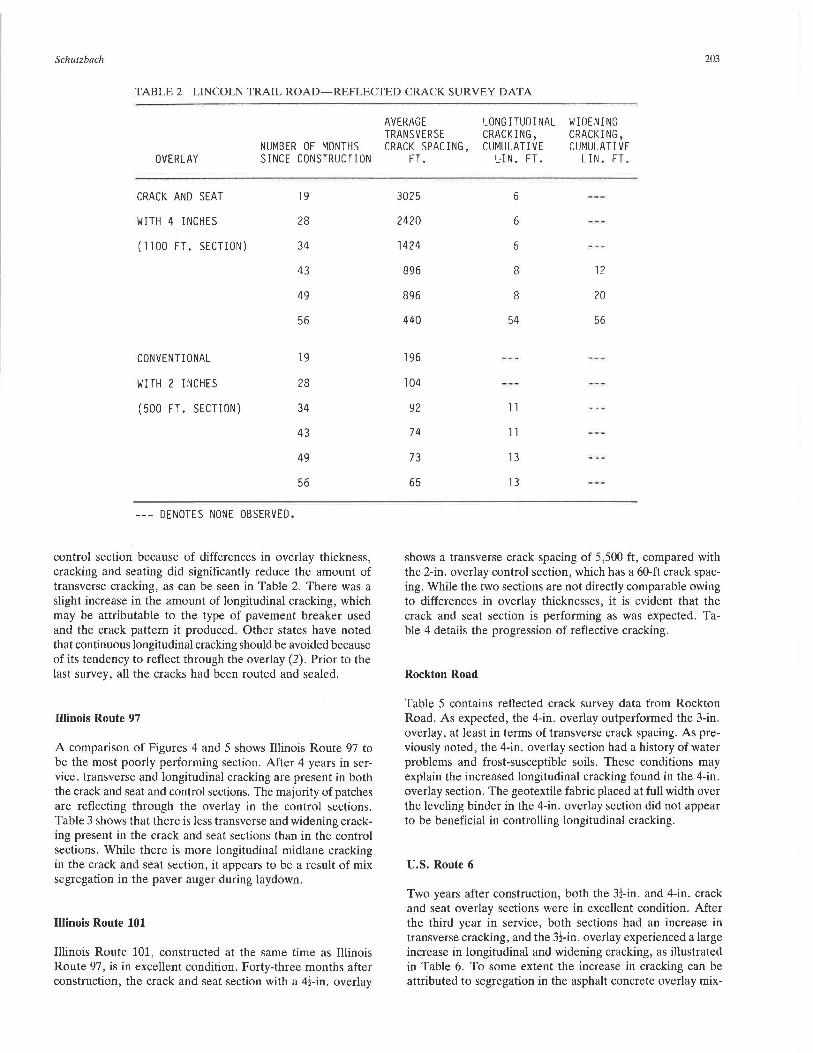
control section because of differences in overlay thickness, cracking and seating did significantly reduce the amount of transverse cracking, as can be seen in Table 2. There was a slight increase in the amount of longitudinal cracking, which may be attributable to the type of pavement breaker used and the crack pattern it produced. Other states have noted that continuous longitudinal cracking should be avoided because of its tendency to reflect through the overlay (2). Prior to the last survey, all the cracks had been routed and sealed.
Illinois Route 97
A comparison of Figures 4 and 5 shows Illinois Route 97 to be the most poorly performing section. After 4 years in service, transverse and longitudinal cracking are present in both the crack and seat and control sections. The majority of patches are reflecting through the overlay in the control sections. Table 3 shows that there is less transverse and widening cracking present in the crack and seat sections than in the control sections. While there is more longitudinal midlane cracking in the crack and seat section, it appears to be a result of mix segregation in the paver auger during laydown.
Illinois Route 101
Illinois Route 101, constructed at the same time as Illinois Route 97, is in excellent condition. Forty-three months after construction, the crack and seat section with a 4!-in. overlay
AVERAGE LONGITUDINAL WIDENING TRANSVERSE CRACKING, CRACKING, CRACK SPACING, CUMULATIVE CUMULATIVE
FT. UN. FT. LIN. FT.
3025 6
2420 6
1424 5
896 8 12
896 8 20
440 54 56
196
104
92 11
74 11
73 13
65 13
shows a transverse crack spacing of 5,500 ft, compared with the 2-in. overlay control section, which has a 60-ft crack spacing. While the two sections are not directly comparable owing to differences in overlay thicknesses, it is evident that the crack and seat section is performing as was expected. Table 4 details the progression of reflective cracking.
Rockton Road
Table 5 contains reflected crack survey data from Rockton Road. As expected, the 4-in. overlay outperformed the 3-in. overlay, at least in terms of transverse crack spacing. As previously noted, the 4-in. overlay section had a history of water problems and frost-susceptible soils. These conditions may explain the increased longitudinal cracking found in the 4-in. overlay section. The geotextile fabric placed at full width over the leveling binder in the 4-in. overlay section did not appear to be beneficial in controlling longitudinal cracking.
U.S. Route 6
Two years after construction, both the 3!-in. and 4-in. crack and seat overlay sections were in excellent condition. After the third year in service, both sections had an increase in transverse cracking, and the 3!-in. overlay experienced a large increase in longitudinal and widening cracking, as illustrated in Table 6. To some extent the increase in cracking can be attributed to segregation in the asphalt concrete overlay mix-

TABLE 3 ILLINOIS ROUTE 97-REFLECTF.D \.RA\.K SURVEY DATA
AVERAGE LONGITUDINAL WIDENING TRANSVERSE CRACKING, CRACKING,
NUMBER OF MONTHS CRACK SPACING, CUMULATIVE CUMULATIVE OVERLAY SINCE CONSTRUCTION FT. LIN. FT. LIN. FT.
CONVENTIONAL 4 36 85
WITH 3 INCHES 10 25 98
(400 FT. SECTION, 16 21 150 12 FT. LANES)
24 20 244
28 19 279
34 18 304
44 17 316
CONVENTIONAL 4 54 21
WITH 2 INCHES 10 36 3 25
(600 FT. SECTION, 16 33 6 37 12 FT. LANES)
24 28 66 64
28 27 95 70
34 26 117 78
44 25 158 94
CRACK AND SEAT 4 889
WITH 4 INCHES 10 333
(1000 FT. SECTION, 12 FT. LANES)
16 238
24 198 99
28 137 357
34 117 396 3
44 77 564 3
CRACK AND SEAT 4 267
WITH 3 INCHES 10 90
(1000 FT. SECTION, 16 56 4 12 FT. LANES)
24 44 6
28 38 4 31
34 35 10 38
44 30 107 82
--- DENOTES NONE OBSERVED.

TABLE 4 ILLINOIS ROUTE 101-REFLECTED CRACK SURVEY DATA
AVERAGE LONGITUDINAL WIDENING TRANSVERSE CRACKING, CRACKING,
NUMBER OF MONTHS CRACK SPACING, CUMULATIVE CUMULATIVE OVERLAY SINCE CONSTRUCTION FT. LIN. FT. LIN. FT.
CRACK AND SEAT 5 co
WITH 4 1/2 INCHES 16 co
(1000 FT. SECTION, 21 co 11 FT. LANES)
27 co
33 co
43 5500
CONVENTIONAL 5 310 28
WITH 2 I NCH ES 16 111 54
(1000 FT. SECTION, 21 86 54 11 FT. LANES)
27 77 54
33 74 54
43 60 58
DENOTES NONE OBSERVED.
TABLE 5 ROCKTON ROAD-REFLECTED CRACK SURVEY DATA
AVERAGE LONGITUDINAL WIDENING TRANSVERSE CRACKING, CRACKING,
NUMBER OF MONTHS CRACK SPACING, CUMULATIVE CUMULATIVE OVERLAY SINCE CONSTRUCTION FT. LIN. FT. LIN. FT.
CRACK AND SEAT 21 558 179
WITH 4 INCHES 26 471 221
(1000 FT. SECTION, 34 381 274 2 12 FT. LANES)
44 115 487 5
CRACK AND SEAT 21 157 59
WITH 3 INCHES 26 110 127
(1000 FT. SECTION, 34 90 150 12 FT. LANES)
44 46 152
--- DENOTES NONE OBSERVED.
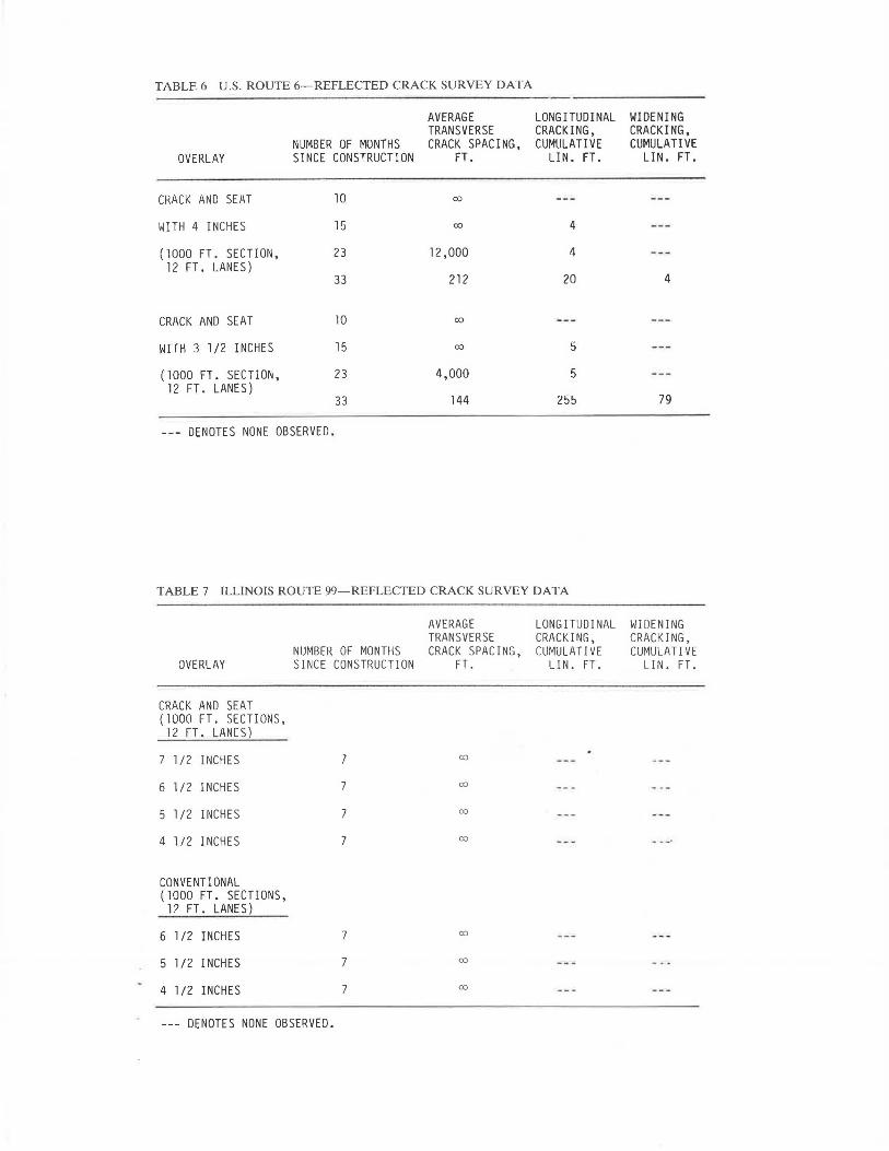
TABLE 6 U.S. ROUTE 6-REFLECTED CRACK SURVEY DATA
AVERAGE LONGITUDINAL WIDENING TRANSVERSE CRACKING, CRACKING,
NUMBER OF MONTHS CRACK SPACING, CUMULATIVE CUMULATIVE OVERLAY SINCE CONSTRUCTION FT. LIN. FT. LIN. FT.
CRACK AND SEAT 10 co
WITH 4 INCHES 15 co 4
{1000 FT. SECTION, 23 12,000 4 12 FT. LANES)
33 212 20 4
CRACK AND SEAT 10 co
WITH 3 1/2 INCHES 15 co 5
(1000 FT. SECTION, 23 4,000 5 12 FT. LANES)
33 144 2!:i!:i 79
--- DENOTES NONE OBSERVED.
TABLE 7 ILLINOIS ROUTE 99-REFLECTED CRACK SURVEY DATA
AVERAGE LONGITUDINAL WIDENING TRANSVERSE CRACKING, CRACKING,
NUMBER OF MONTHS CRACK SPACING, CUMULATIVE CUMULATIVE OVERLAY SINCE CONSTRUCTION FT. LIN. FT. LIN. FT.
CRACK AND SEAT {1000 FT. SECTIONS,
12 FT. LAN[S)
7 1/2 INCHES 7 co
6 1/2 INCHES 7 co
5 1/2 INCHES 7 00
4 1/2 INCHES 7 00
CONVENTIONAL (1000 FT. SECTIONS,
12 FT. LANES)
6 l /2 INCHES 7 00
5 1/2 INCHES 7 00
4 1/2 INCHES 7 00
--- DENOTES NONE OBSERVED.

4000
3600
3200
~
LL.~2800 (!) z 0 ~ (/)
02400 <( 0::: u w (/)
ffi2000 > (/) z <(
0::: t-w 1600 > ti -' :::> ~ 1200 u
800
400
0-0 LINCOLN TRAIL CSS w/4110L
tr -6 LINCOLN TRAIL CONY. w/2110L
D-DU.S. RT. 6 CSS w/411
0L
0-0 U.S. RT. 6 CSS w/3.5110L
~- -- --&----c:r- ---- -6- ----0-----6 00'--~4'--~0'--~~,2~----L,6~__.20~-----'24~-----'2~8~~3~2~-3~6~-4-'-o-·~4~4~-~-g~s
MONTHS SINCE CONSTRUCTION
FIGURE 5 Transverse crack spacing versus time for Lincoln Trail and U.S. Route 6.

Schutzbach
i--: l.J..~ 700 (.!)
~ u ~ (/)
:x:: 600 u <t cc u w (/)
a:: 500 w > (/)
z <t a:: I- 400 w > ~ ...J :::> ~ 300 :::> u
200
100
4
' '
8
' ' \ ' \
\
' \ \
12 16 20 24 28 32 36 40 44 48 52 56 MONTHS SINCE CONSTRUCTION
FIGURE 4 Transverse crack spacing versus time for Illinois Routes 97, 101, and Rockton Road.
207
Schutzbach
ture. The open texture of the mix allowed water infiltration and promoted crack formation. The geotextile fabric strip over the longitudinal widening joint appears to be working, as only minimal cracking is evident 3 years after construction.
Illinois Route 99
After 1 year in service, all of the crack and seat and control sections are in excellent condition with no signs of reflective cracking. Table 7 gives the crack survey data for Illinois Route 99.
DISCUSSION AND CONCLUSIONS
Two factors make it difficult to assess accurately the ability of cracking and seating to reduce reflective cracking: lack of traffic and lack of control sections. Five out of the six test sections receive less than 100 multiunits a day. The sixth section, Illinois Route 99, has 238 multiunit and 119 single-unit trucks per day, for a total of 440, 18-kip equivalent single axle loads (ESALs) per day. More important, because of a lack of comparable control sections, it is difficult to tell what absolute benefits are directly derived from the cracking and seating process and which are attributable to the increased overlay thickness. Of the first five projects constructed, only one features a short control section with an overlay thickness equal to the overlay thickness on a cracked and seated section. Conversely, the recently constructed Illinois Route 99 has three control sections that correspond to crack and seat overlay thicknesses. For these reasons, Illinois Route 99 promises to be the most comprehensive test of cracking and seating in Illinois. This section will continue to be monitored to gain further information on the effectiveness of the crack and seat process.
Although the majority of the projects were constructed without proper control sections and on pavements with relatively low traffic volumes, certain observations can still be made. Illinois Route 97 has both a crack and seat section and a control section with a 3-in. overlay. While the crack and seat sections on Illinois Route 97 are performing poorly, they are still in better condition than the control sections. Table 3
TABLE 8 PROJECT COST INFORMATION
CRACK & SEAT COST, PROJECT $ PER SQUARE YARD
Lincoln Trail l. 70
Illinois Route 97 0.55
I 11 i noi s Route 101 l.00
Rockton Road 0.55
U.S. Route 6 3.00
Illinois Route 99 0. 51
209
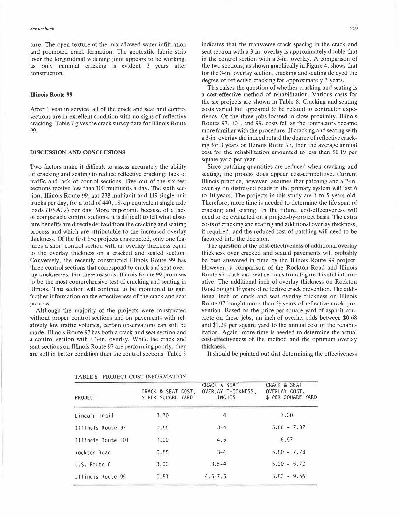
indicates that the transverse crack spacing in the crack and seat section with a 3-in. overlay is approximately double that in the control section with a 3-in. overlay. A comparison of the two sections, as shown graphically in Figure 4, shows that for the 3-in. overlay section, cracking and seating delayed the degree of reflective cracking for approximately 3 years.
This raises the question of whether cracking and seating is a cost-effective method of rehabilitation. Various costs for the six projects are shown in Table 8. Cracking and seating costs varied but appeared to be related to contractor experience . Of the three jobs located in close proximity , Illinois Routes 97, 101, and 99 , costs fell as the contractors became more familiar with the procedure. If cracking and seating with a 3-in. overlay did indeed retard the degree of reflective cracking for 3 years on Illinois Route 97, then the average annual cost for the rehabilitation amounted to less than $0.19 per square yard per year.
Since patching quantities are reduced when cracking and seating, the process does appear cost-competitive. Current Illinois practice, however , assumes that patching and a 2-in. overlay on distressed roads in the primary system will last 6 to 10 years. The projects in this study are 1 to 5 years old . Therefore, more time is needed to determine the life span of cracking and seating. In the future, cost-effectiveness will need to be evaluated on a project-by-project basis. The extra costs of cracking and seating and additional overlay thickness, if required, and the reduced cost of patching will need to be factored into the decision.
The que tion of the cost-effective11css of additional verlay thickness over cracked and seated pavements will probably be best answered in time by the Illinois Route 99 project . However, a comparison of the Rockton Road and Illinois Route 97 crack and seat sections from Figure 4 is still informative . The additional inch of overlay thickness on Rockton Road bought H years of reflective crack prevention. The additional inch of crack and seat overlay thickness on Illinois Route 97 bought more than 2! years of reflective crack prevention . Based on the price per square yard of asphalt concrete on these jobs, an inch of overlay adds between $0.68 and $1.29 per square yard to the annual cost of the rehabilitation. Again, more time is needed to determine the actual cost-effectiveness of the method and the optimum overlay thickne s .
It should be pointed out that determining the effectiveness
CRACK & SEAT CRACK & SEAT OVERLAY THICKNESS, OVERLAY COST,
INCHES $ PER SQUARE YARD
4 7.30
3-4 5.66 - 7.37
4.5 6.57
3-4 5.80 - 7.73
3.5-4 5.00 - 5. 72
4.5-7.5 5.83 - 9.56

210
of geotextile fabrics in preventing reflective cracking over the pavement widening joint was outside the scope of this study The fabric was used on three projects at the district's option . The Illinois Department of Transportation has previously published research on the use of fabrics in pavement rehabilitation ( 4).
Although Illinois Route 97 is the most poorly performing section, it was the only pavement in the study that contained reinforcing steel. Falling Weight Deflectometer tests done on the experimental sections after cracking, seating, and overlaying indicated an average concrete modulus of almost 3,UUU,UUU psi on lllinois Route 97. Concrete moduli values from the other cracked and seated pavements averaged 546,000 psi. These values are listed in Table 9. Such a high modulus value on the Illinois Route 97 project would seem to indicate that the reinforcing steel was not adequately broken during the cracking process. The steel still held the concrete together, and as it expanded and contracted in response to temperature variations, stresses developed in the overlay and resulted in einly reflective cracking. Other studies have confirmed that jointed reinforced pavements are not suited to cracking and seating (5).
Information provided by Marshall Thompson of the University of Illinois also indicated the importance of adequately breaking the concrete . Willard Airport Road in Savoy, Illinois , is under the jurisdiction of the University of Illinois. This 7-in. plain Portland cement concrete pavement was cracked
TRA NSPORTATION RESEARCH RECO RD 1215
and seated in 1984. The pavement was cracked with a spring;irm h;immer on ;i very hot <fay ;inn overlaid with 4 in. of asphalt concrete. Reflective cracking appeared very early. Falling Weight Deflectometer tests performed after cracking, seating, and overlaying indicated an average concrete modulus of 4,050,000 psi, a value similar to that of unbroken concrete. These test data are found in Table 9. The extremely hot conditions put the concrete in compression, and apparently the spring-arm hammer was not able to crack the pavement. Both Illinois Route 97 and Willard Airport Road of the University of Illinois indicate the importance of establishing a test section where the cracking pattern can be varied and full-depth cracking verified.
Both pavements exhibiting early reflective cracking due to insufficient slab cracking were broken with a hydraulic-powered spring-arm hammer. Coring and Falling Weight Deflectometer (FWD) testing on the Illinois Route 99 section, which was cracked with a guillotine hammer, verified full-depth cracking. Based on the results of the FWD testing and the surveys showing early reflective cracking, it appears that a guillotine-type hammer is best suited to provide the desired full-width, full-depth cracking pattern.
The seating process is equally important as the cracked pieces must be firmly seated on the subgrade or they will rock and produce reflective cracking. While both 35-ton and 50-ton rubber tire rollers were used to seat the experimental sections, current practice favors the 35-ton roller , especially
TABLE 9 CRACKED AND SEATED CONCRETE MODULI VALUES
PAVEMENT TEST DATE
LINCOLN TR/\IL SUMMER/FALL 1985 LINCOLN TRAIL SPRING 1986
ILLINOIS 97 - 3 IN. SUMMER/FALL 1985 ILLINOIS 97 - 3 IN. SPRING 1986 ILLINOIS 97 - 4 IN. SUMMER/FALL 1985 ILLINOIS 97 - 4 IN. SPRING 1986
ILLINOIS 101 SUMMER/FALL 1985 ILLINOIS 101 SPRING 1986
ROCKTON ROAD SPRING 1985 ROCKTON ROAD SPRING 1986 ROCKTON ROAD SUMMER/FALL 1986
u. s. 6 - 3.5 IN. SUMMER/FALL 1986 u. s. 6 - 4 IN. SUMMER/FALL 1986
WILLARD AIRPORT RD. SUMMER/FALL 1985 WILLARD AIRPORT RD. SPRING 1986
FALLING WEIGHT DEFLECTOMETER l 9,000 LB. LOAD DEFLECT! ON, MI LS
7. 8 8.4
7.3 7.8 8.7 7.3
14.2 10. l
14.0 13. 7 12.3
14.7 12.2
7.7 5.3
Dynatest 8002 Falling Weight Oeflectometer
CRACKED AND SEATED CONCRETE MODULI,2
KSI
1,080 770
3,250 1,850 4,000 2,400
420 600
150 240 300
680 670
4, 100 4,000+
2 Cracked and seated concrete moduli back-calculated using the finite-element program ILLIPAVE.

Schutzbach
on sections with weak subgrades (5). Steel wheel rollers and vibratory rollers are not recommended because they bridge the pieces and do not adequately seat tJ1em. Determination of adequate seating is somewhat subjective. In Illinois, an upper limit of five one-way passes per lane is used. The resident engineer then makes a visual inspection of the seating operation and a judgment call regarding the number of roller passes. The roller passes are staggered to ensure full-width coverage. Additional research is needed to develop a more objective method of determining if the cracked pieces are adequately seated.
RECOMMENDATIONS
Based on the observations made on the six experimental sections, the following recommendations are offered:
• A 100-ft test section should be designated on each job. The drop height and spacing of the pavement breaker can be varied to obtain the desired crack pattern. Cores should be taken over a crack to verify that full-depth cracking is taking place.
• A light spray of water should be applied to the test section after cracking to highlight the crack pattern.
• Certain precautions must be taken when cracking through an exi ting a phalt overlay. Asphalt concrete overlay test tdps should be removed in SO-f1 lengths to verify that the underlying concrete pavement is being cracked. These test strips should be located along the entire length of the job, as pavement condition and overlay thickness may vary and thus cause the crack pattern to vary.
• Guillotine-type hammers or heavy, guided, free-falling drop weights capable of producing full-width, fu ll-depth cracking are recommended for the cracking process.
• Traffic can safely be maintained adjacent to the pavement breaker. Traffic can also be allowed on the cracked pavement prior to seating and on the cracked and seated pavement prior to overlaying, provided that the pavement is patched and swept a needed . The cracked pavement should be rolled prior to overlaying if it has been open to traffic for a long peri.od of time. Care should be taken to en ure that the cracked pavement is overlaid prior to winter.
• One to five one-way passes per lane with a 35-ton rubber tire roller should be sufficient to seat the cracked pieces onto the subgrade. The passes should overlap to ensure full-lane coverage .
• Use of the crack and seat process on reinforced concrete pavements is not recommended at this time. Thickened edge pavements containing edge bars are suitable for cracking and seating prior to overlaying.
• Overlay thicknesses should be carefully designed on the
211
basis of traffic, subgrade support, and asphalt concrete and cracked and seated concrete moduli values.
A sample specification incorporating these recommendations has been developed. ( 6).
ACKNOWLEDGMENTS
This paper is based on the results of the project, "Evaluation of Crack and Seat Method of Resurfacing," which was sponsored by the Illinois Department of Transportation, Division of Highways, and the U.S. Department of Transportation, Federal Highway Administration.
REFERENCES
I. R. A. Eckroscand W. E. Poston , Jr . Asphalt Overlays on racked and Seated oncrete Pavement . N11tio11nl A plwlt Pnvemelll Association /11for111ntio11 Series 83. National Asphalt Pavement A o· ciation, Riverdale, Md. July 1982, 16 pp.
2. . Crawford. racking and eating of P Pavement Prior to Overlaying with Hot Mix A phah- taU~·Of· the-Arl. Na1io11nl Asphalt Pnve111e111 Association l11/ormatio11 'Jeries 91. National Asphalt Pavement A ciation Riverdnlc, Md., March 1985, 10 pp.
3. Cracking n11d Senting of P P"vemellls Prior to Asp/wit Ove.rlny . Audio-Visual Program . The A phalt Institute College Park. Md. , 1984.
4. I. . Ma cunana. An Eva/11"tio11 of Engineering Fnbric in Pn1111-111e11f Relwbilitnt/011. Phy ical Research Report· 88. llllnois Depart· ment of Tran portation , Bureau of Material and Physical Research ,
pringfield March 1981 , 41 pp. 5. ERES Consultants, Inc. Techniques for P"veme111 Relrabilitntio11 ,
3rd rev. Training Cour:;e. U . . Depa.rtment of Transportation, Federal Hjghway Administration , and National Highway In tilute. Champaign m .. October 1987, pp. 731-760.
6. A. M. Schutzbach. Tire Crack n11d ent Method of Pnveme11f Rehn/Jilillltion . Physical Research Project 104. Illinois Department of Transportation , Bureau of Materials and Phy ical Research , Springfield, July 1988, 50 pp.
The co111e111 of tlu"s pt1p r reflect the vieivs of tire m1thor, ivho is responsible for the [nets fmd accw·ncy of the dnta presented herein. 'n1e comems do 11ot 1iec<!.W1rily reflect the officinl 11iews or policies of 1/ie llli11ois Department of Trn11sportntion or the Federal Hig/11vay Admi11istrntio11. Tliis paper does 11oi consti//.lte a tn11dnrd, specification , or reg11/ntio11 . Tmdemnrks or 111111111fnc111rers' 11<1mes <tppe(Jr in /his repor1 011/y becnuse /hey are considered i!Jsential to the object of 1/1is doc11111e111 nfl(/ do 11ot co11s1itute 011 e11dor.1·cme11t of prod11e1 by 1/ie Fc11Jernl Highway Admi11istrntio11 or Ille ll/i11ois Dep"rt111e111 of Transportation.
Publication of this paper sponsored by Committee on Pavement Relinbilitation.