cr 550 rollingg arag e door opener installation and … · cr 550 rollingg arag e door opener...
TRANSCRIPT

CR550Roll ing Garage Door Opener
Inst allat ion and Operat ing Inst ruction s
www. chamberl aindiy.com.au
Owners Copy: Please keep these instru ct ions for fut ure reference
This manual cont ains IMPORTANT SAFETY informationDO NOT PROCEED WITH THE INSTALLATION BEFORE READING THOROUGHLY
1
CONTENTS PAGESAFETY INSTRUCTIONS . . . . . . . .1CARTON INVENTORY . . . . . . . . . .2TOOLS REQUIRED . . . . . . . . . . . .2DOOR REQUIREMENTS . . . . . . . .2PREPARE & TEST THE DOOR . .3-4INSTALLATION . . . . . . . . . . . . . .5-6CONNECT ELECTRIC POWER . . .7ADJUSTMENT . . . . . . . . . . . . . . .7-8INSTALL THE PROTECTORSYSTEM (IR BEAMS) . . . . . . . . . . .9
WIRELESS PROGRAMMING .10-11SPECIAL FEATURES . . . . . . . . . .12ACCESSORIES . . . . . . . . . . . . . . .12TROUBLESHOOTING . . . . . . . . . .13OPERATION OF YOUR OPENER 14CARE OF YOUR OPENER . . . . . .14MAINTENANCE OF YOUR OPENER 14SPECIFICATIONS . . . . . . . . . . . . .14WARRANTY . . . . . . . . . . . . . . . . .15
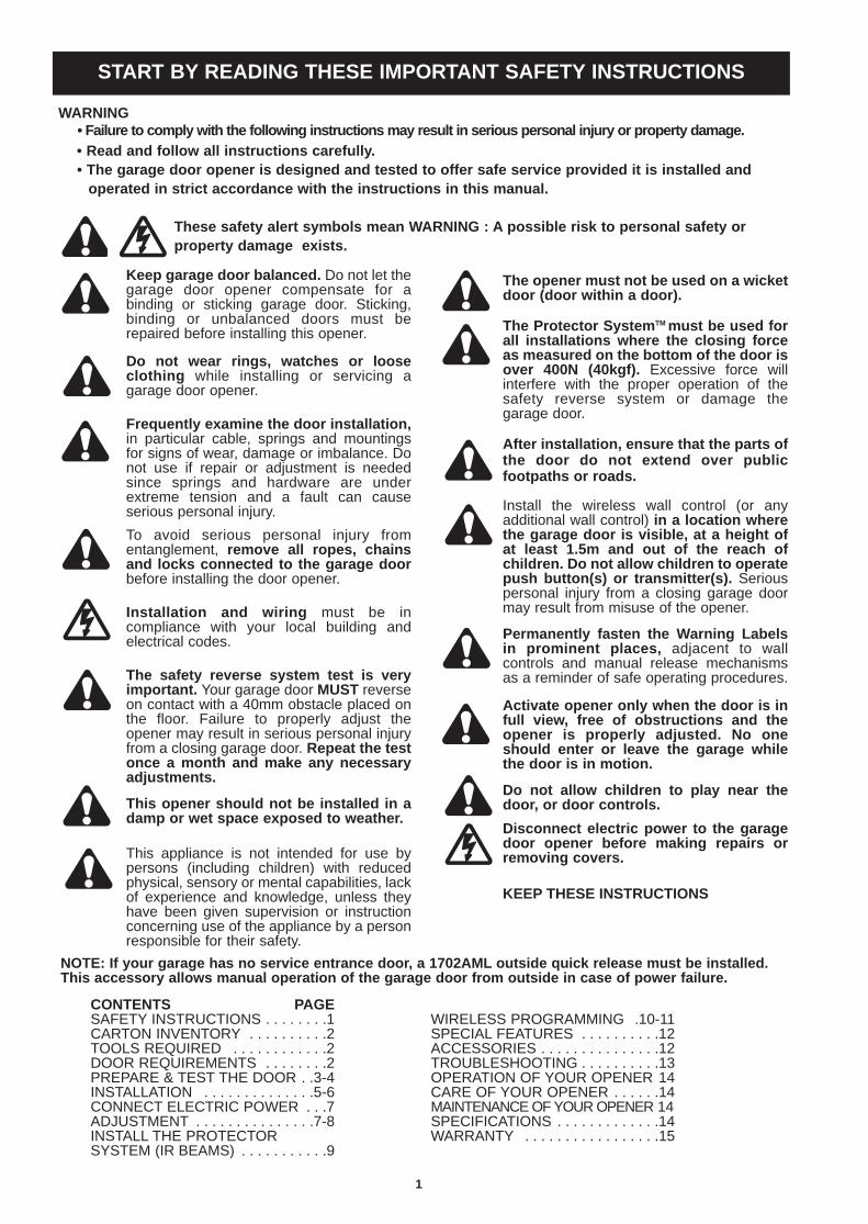
The opener must not be used on a wicketdoor (door within a door) .
The Protector Syst emTMmust be used forall inst allations where the closi ng forceas measure d on the bot tom of the door isover 400N (40kgf ). Excessive force willinterfere with the proper operation of thesafety reverse system or damage thegarage door.
After inst allation, ensur e that the part s ofthe door do no t extend over publicfoot paths or roads.
Install the wireless wall control (or anyadditional wall control) in a locat ion wher ethe garage door is visible, at a height ofat least 1.5m and out of the reach ofchi ldren. Do not allow chi ldren to operat epush but ton(s) or transmi tter(s). Seriouspersonal injury from a closing garage doormay result from misuse of the opener.
Permanent ly fasten the Warni ng Labelsin prominent places, adjacent to wallcontrols and manual release mechanismsas a reminder of safe operating procedures.
Act ivate opener onl y when the door is inful l view, free of obst ruct ions and theopener is pro perly adjusted. No oneshoul d enter or leave the garage whilethe door is in mot ion.
Do not allow chi ldren to play near thedoor , or door cont rol s.
Disconnec t elect ric power to the garagedoor opener befor e making repairs orremovi ng cove rs.
KEEP THESE INSTRUCTIONS
WARNING• Failure to comp ly with the following instructions may result in serious personal injury or property damage.• Read and follow all ins truct ions carefully.• The garage door opener is des igne d and tested to off er safe service provided it is installed andoperated in stric t accor dance wit h the instructions in this manual.
These safety alert symbols mean WARNING : A possible risk to personal safety orproperty damage exist s.
NOTE: If your garage has no servic e entran ce doo r, a 1702AML outside quick release must be installed.This access ory allows manual operation of the garage door from outside in case of power failure.
Keep garage door balanced . Do not let thegarage door opener compensate for abinding or sticking garage door. Sticking,binding or unbalanced doors must berepaired before installing this opener.
Do not wear rings, watches or looseclo th ing while installing or servicing agarage door opener.
Frequentl y examine the door inst allat ion,in particular cable, springs and mountingsfor signs of wear, damage or imbalance. Donot use if repair or adjustment is neededsince springs and hardware are underextreme tension and a fault can causeserious personal injury.
To avoid serious personal injury fromentanglement, remov e all ropes, chainsand loc ks conn ected to the garage doorbefore installing the door opener.
Installatio n and wi ring must be incompliance with your local building andelectrical codes.
The safety reverse syst em test is veryimportant. Your garage door MUST reverseon contact with a 40mm obstacle placed onthe floor. Failure to properly adjust theopener may result in serious personal injuryfrom a closing garage door. Repeat the testonc e a mont h and make any neces saryadjus tments .
This opene r sho uld not be inst alled in adamp or wet space expos ed to weathe r.
This appliance is not intended for use bypersons (including children) with reducedphysical, sensory or mental capabilities, lackof experience and knowledge, unless theyhave been given supervision or instructionconcerning use of the appliance by a personresponsible for their safety.
START BY READING THESE IMPORTANT SAFETY INSTRUCTIONS

2
1. Instruction manual (this document)2. Warning and risk of entrapment labels3. Hardware bag4. Release handle, cord and risk of entrapment card5. 2 x 3 Channel mini transmitter6. Wall or visor mounted transmitter7. Stop collar8. Clamp bracket and plate9. Weight bar
10. 2 x Extension poles & 1 x brace
CARTON INVENTORY1
1 2 3
45
6
7 8
910
TOOLS REQUIRED2
1. Ladder2. Adjustable wrench for U-bolts already installed
on the door3. 8mm socket, 10 mm socket and 13 mm extended
socket and socket wrench4. 300 mm socket extension (for minimum side-room
installations)5. Drill and 5.5 mm drill bit6. Phillips-head screwdriver7. Marker pen8. Door stand or similar device to safely support door
(not shown)
DOOR REQUIREMENTS3
Ensure that there is at least 45mm from the edge of the curtain to the edge of the bracket. If the roller doordrum is on the edge of the curtain or is a smaller diameter, additional clearance may be required.If the drum is more than 60mm from the curtain edge or of a smaller diameter, extens ion pole s may berequired (see section 7).Different drum and bracket types may result in the minimum side room clearance not being possible andextension poles being required. Ensure there is a power point near the opener.
Independent clampi ng method Direct clampin g metho d
The maximum allowable door height is 3.5m with a maximum curtain area of 13.5 m² (door height in metresmultiplied by the width in metres). The door must be spring balanced.The Protector System™ (IR Beams) must be installed if the force at the edge of the closing door exceeds 400N(40kgf). Door axle diameter must not exceed 35mm.
Door areah x w = m2
eg. 2.5 x 3 = 7.5m2
fig A fig B

TESTING THE DOOR
Complete the foll owing test to ensure your door is wellbalan ced, and not stic king or binding:
• Disable all locks and remove any ropes connected tothe garage door.
• Lift the door to about halfway and then release it. Thedoor should remain suspended entirely by its spring.
• Raise and lower the door to determine if there are anysticking or binding points (20 kgf is the absolute maximumallowable to raise or lower the door in any position).
• If your door does not hold in place or it binds or sticks,call a qualified door technician before installing the opener.
Non opener side Opener side• Install stop bracket collar on the opposite end towhere the opener is to be installed.
• Fit the stop bracket hard against the boss of the doordrum. Ensure the U-bolt holding the door axle to thedoor bracket is tightly secured.
INSTALLING THE STOP COLLAR5
INSTALLING THE WEIGHT BAR (PROVIDED)6
SAFETY CHECK!Is stop collar installed?
YESProceed to the next step
NO
Install the stop collarbefore proceeding
4
3
• Place the weight bar in the centre of the door.
• If the door curtain does not have a lifting handle youwill need to drill two 5.5 mm holes through the twomarked positions, then place the weight bar on theinside of the door.
• Use the 5 mm bolts, washers and nuts (provided) tofasten the weight bar in place.
NOTE: If the door has a lift ing handl e, remove thehandle, nuts & bolts . Place weight bar over thehandle hole s, insert extended bol ts through theweight bar & fasten hand le back in place.
4
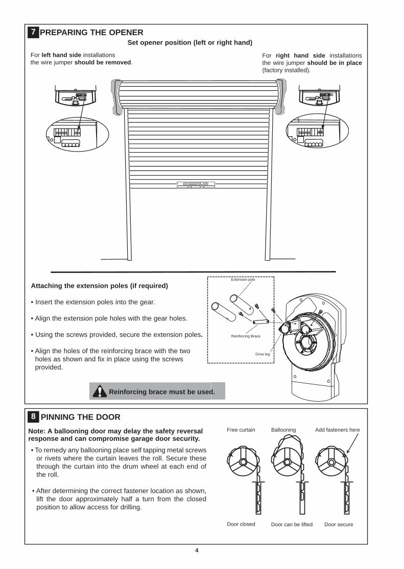
PREPARING THE OPENER7
For left hand side installationsthe wire jumper shoul d be removed.
For right hand side installationsthe wire jumper shou ld be in place(factory installed).
Set opener posit ion (left or right hand)
Extension pole
Reinforcing Brace
Drive leg
Note: A bal looning door may delay the safety reversalresponse and can compr omise garage door secur ity.
• To remedy any ballooning place self tapping metal screwsor rivets where the curtain leaves the roll. Secure thesethrough the curtain into the drum wheel at each end ofthe roll.
• After determining the correct fastener location as shown,lift the door approximately half a turn from the closedposition to allow access for drilling.
8
Free curtain Ballooning Add fasteners here
Door closed Door can be lifted Door secure
PINNING THE DOOR
Atta chin g the extension pole s (if require d)
• Insert the extension poles into the gear.
• Align the extension pole holes with the gear holes.
• Using the screws provided, secure the extension poles.
• Align the holes of the reinforcing brace with the twoholes as shown and fix in place using the screwsprovided.
Reinfor cing brace must be used.
5
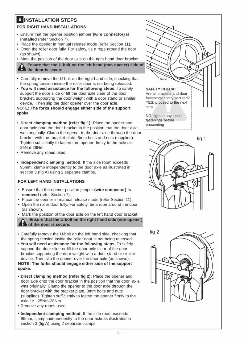
INSTALLATION STEPS9FOR RIGHT HAND INSTALLATION S
• Ensure that the opener position jumper (wi re conne ctor) isinstalled (refer Section 7).
• Place the opener in manual release mode (refer Section 11).• Open the roller door fully. For safety, tie a rope around the door
(as shown).• Mark the position of the door axle on the right hand door bracket.
• Carefully remove the U-bolt on the right hand side, checking thatthe spring tension inside the roller door is not being released.
• You will need assist ance for the following steps . To safelysupport the door slide or lift the door axle clear of the doorbracket, supporting the door weight with a door stand or similardevice. Then slip the door opener over the door axle.
NOTE: The fork s should engage eithe r side of the supportspoke.
• Direct clamping method (refer fig 1): Place the opener anddoor axle onto the door bracket in the position that the door axlewas originally. Clamp the opener to the door axle through the doorbracket with the bracket plate, 8mm bolts and nuts (supplied).Tighten sufficiently to fasten the opener firmly to the axle i.e.25Nm-28Nm.
• Remove any ropes used.
• Independe nt clamping method: If the side room exceeds95mm, clamp independently to the door axle as illustrated insection 3 (fig A) using 2 separate clamps.
FOR LEFT HAND INSTALLATIONS
• Ensure that the opener position jumper (wi re conne ctor) isremoved (refer Section 7).
• Place the opener in manual release mode (refer Section 11).• Open the roller door fully. For safety, tie a rope around the door
(as shown).• Mark the position of the door axle on the left hand door bracket.
• Carefully remove the U-bolt on the left hand side, checking thatthe spring tension inside the roller door is not being released.
• You wil l need assist ance for the following steps . To safelysupport the door slide or lift the door axle clear of the doorbracket supporting the door weight with a door stand or similardevice. Then slip the opener over the door axle (as shown).
NOTE: The fork s should engage eithe r side of the supportspoke.
• Direct clampi ng method (refer fig 2): Place the opener anddoor axle onto the door bracket in the position that the door axlewas originally. Clamp the opener to the door axle through thedoor bracket with the bracket plate, 8mm bolts and nuts(supplied). Tighten sufficiently to fasten the opener firmly to theaxle i.e. 25Nm-28Nm.
• Remove any ropes used.
• Independent clamping method: If the side room exceeds95mm, clamp independently to the door axle as illustrated insection 3 (fig A) using 2 separate clamps.
Ensure that the U-bolt on the left hand (non opener) side ofthe door is secure.
Ensure that the U-bolt on the right hand side (non opener)of the door is secure.
fig 1
Rope
SAFETY CHECK!Are all brackets and doorfastenings tightly secured?YES: proceed to the nextstep
NO: tighten any loosefastenings beforeproceeding
fig 2

10
• Thread one end of the rope through the hole in the top ofthe red handle so “NOTICE” reads right side up asshown.
• Secure with an overhand knot at least 25 mm from theend of the rope to prevent slipping.
• Thread the other end of the rope through the loop of themanual release cable.
• Adjust the rope length so the handle is no higher than1.8 m above the floor. Secure with an overhand knot. Ifthe door is greater than 2.5 m in height the release cordextension kit accessory is required.
NOTE: Final adjustm ent of the handle height should becompleted after the opener is install ed. If it isnecessar y to cut the rope, heat seal the cut end toprevent unrave ll ing.
6
OPERATING THE MANUAL RELEASE
To disengage the opener
Pull the release cord down once until you hear aclicking sound. The door is now in manual mode andmay be opened or closed.
To re-engage the opener
To re-engage the opener, pull the release cord downuntil you hear a clicking sound, the motor is now readyfor operation.
Disable all lock s and remove any rope sconne cted to the garage door . Take care
when opera ting the manual release as an opendoor may fall rapidly due to weak or broke nsprings, or being out of balanc e.
ATTACH THE RELEASE HANDLE AND CORD
11
Release cord
Rope
Manual releaseWarning label
Release handle
Overhand knot
release cord
pull
dow
n

Travel limits regulate the points at which the door willstop when moving UP or DOWN. During the set upprocedure, the motor will run and operate the door.The opener must be fully installed on the door and allinstallation steps completed before proceeding.
PREPARATION:• Position the door about half way and engage the
opener (section 11).• Remove the lens cover from the opener (fig 1).
• Connect the opener to a 240 VAC power point andturn on.
SETTING THE TOP LIMIT:
• Press and hold the black limit button until theorange indicator LED starts flashing slowly, andthen release. The courtesy LEDs will go to lowillumination.
• Press and hold the black limit button, until the doorreaches the desired open position. If set too high,adjust down using the pur ple learn button (makesure there is enough room for your vehicle to passunder).
SETTING THE BOTTOM LIMIT:
• Press and release the green start button, this setsthe UP limit and begins closing the door, once theopener starts to move down, IMMEDIATELY pressand hold the purp le learn button until the doorreaches the desired closed position, then releasebutton. For fine adjustment press and release thepurple learn button to inch down.
SAVE AND TEST:
• Press and release the green start button, this setsthe DOWN position and begins opening the doorto the fully open position.
• Close and open the door 3 or 4 times using thegreen start button to confirm the limit settings.Courtesy LEDs should now be fully illuminated.Repeat the above procedure if necessary.
NOTE:The force must now be set in order tocomplete your ins talla tion (refer section 13).
12
Ensure motor is engaged
Press and hold black button
Flashing orange LEDcourtesy LED dim
Use the black button to adjust up(use purple down to adjust if required)
Press start button located on thebottom of motor, then immediatelypress the purple button.
Press and hold the purple buttonuntil the door is closed.Use the black button to adjust upif required.
Press the green start button toopen the door and save the limits.
Press the green start button toclose the door and complete test.
Orange LED will go out and courtesyLEDs will light up brightly.
CR550
www.chamberlaindiy.com.au
7
The opener will oper ate duri ng thisproce dure. Make sur e the door is clear of
obstructi on. Ensu re you r hands are away fromany moving parts before act ivat ing the door.
SETTING THE LIMITS
fig 1
(refer section 11)

The force, as measured on the closing edge of the door,should not exceed 400 N (40 kg). If the closing force ismeasured to more than 400 N, The Protector SystemTM
(IR Beams) must be installed (refer section 16).
The force setting regulates the amount of powerrequired to open and close the door.
• Door should be close d befor e proceeding.• Press the purple button twice to enter the opener into
force adjustment mode. The indicator LED will flashquickly.
• Press the green start button on the bottom of theopener. The door will travel to the up limit. Press thegreen start button again, the door will travel to thedown limit. The indicator LED will stop flashing whenthe force has been learned.
• The door must travel through a complete cycle, up anddown, in order for the force to be set properly. If theopener cannot open and close your door fully,examine your door to ensure that it is balancedproperly and is not sticking or binding (refer section 4).
Press the purple learn buttontwice
FAST flashing orange LED
Press the green startbutton to open the door.
Press the green startbutton to close the door.
13
Operate the door in the down direction. The door must reverseupon contact with the obstacle. If the door stops on the obstacle,remove obstacle and repeat limit and force setting (sections 12 &13). Repeat testing procedur e of the safety reverse system.
14
8
This test shoul d be repeated monthl y to ensure the safe operati on of your opener.
Once you have completed your installation andsuccessfully carried out the safety reverse systemtest (outlined above), install the warning labelsprovided with your opener as shown.
The risk of entrapm ent label must be installedadjacent to the release handle at a height of less than1.8 m from the floor.
The WARNING label must be installed in a prominentplace near any fixed control.
Any fixed wall control or wireless door control must bemounted at a height of no less than 1.5 m out of thereach of chil dren.
Ensure the instruction card concerning the manualrelease of the door is attached to the rope as detailedin section 10.
Read the safety instructions (page 1) for furtherdetails concerning safety.
15 FIXING WARNING LABELS
The safety reverse system test is import ant. The garagedoor mus t reverse on conta ct with a 40mm obs tacle laid
flat on the floor. Failure to properly adjust the opener mayresult in serious persona l injur y from a closing garage door.
40mm test obstacle
STANDARD INSTALLATION COMPLETE
SETTING THE FORCE
TESTING THE SAFETY REVERSE SYSTEM

NOTE: This accessory must be used for allinstallations where the closing force as measur edon the bottom of the door is over 400 N (40 kgf).
After the opener has been installed and adjusted, theProtecto r System™ (IR Beams) accessory can beinstalled. Instructions are included with this accessory.
The Protec tor Syst em™ (IR Beams) provide s anadditional measure of safety against a small childor animal being trappe d under a garage door. Ituses an infra-red beam, which when broken by anobstruction, causes a closing door to open andprevents an open door from closing and is stronglyrecommen ded for homeow ners with youngchildren.
Installing and adjus ting:• Close the garage door.• Turn the opener off.
• Install the Protector SystemTM (IR Beams) using thebrackets, wires and instructions provided with theproduct.
• Twist the two white (only) wires together andterminate them into the white “safety beam” terminal.Twist the two white/black wires together andterminate them into the grey “safety beam” terminal.
• Ensure the trim pot on the opener is set to 0s.• Turn the opener on.• Allow 5 minutes for the beams to self-learn to the
unit, (do not walk through the beam during this time).• Adjust the trim pot to the desired closing time.
NOTE: The opener will autom atically detect theProtecto r SystemTM (IR Beams) when it is insta lledand opera ting for 5 minutes (during this time thebeams must remain unobstr uct ed). The opene r willnot close unle ss the beams are aligned.
Red LEDMUST BE ON
Red LEDMUST BE ON
IR Beam IR Beam
IR Beams must be installedto detect a 100mm high
obstacle at any point alongthe floor.
16
SAFETY FIRST!Whilst Chamberlain have engineered safety features into your garage door opener, we urge you to consider fittingIR Beams to your new garage door opener. In many countries these devices are compulsory to assist inpreventing serious injury or property damage. For your own peace of mind and the safety of others please installthis inexpensive safety device.
INSTALL THE PROTECTOR SYSTEM™ (IR BEAMS)
greywhite
whitewirestwistedtogether
white/blackwirestwistedtogether
Remove cover: Push cover plate up,then lever out from the button.
9
Door may operate unexpect edly , there fore do not allow anything to stay in the path of the doo r.

10
ADDING trans mitters using the learn button• Press and hold down the transmitter button you wish
to program to the opener.• The orange LED will flash continuously to indicate it is
receiving signal from the transmitter.• Press and release the learn button on the opener.• The courtesy LED will flash once.• Ensure the door is clear of obstruction, then test the
transmitter.
DELETING ALL transm itt er code s
NOTE: This deletes all learned transmitters.
• Press and hold the learn button until theorange indicator light goes out (approximately 9 sec).
17
Activa te the opener only when door is in full view , free of obstruction and proper ly adjusted. Noone should enter or leave garage whilst door is in motion. Do not allow childre n to operate pushbut ton(s) or trans mit ter(s). Do not allow children to play near the door.
Fix any wall cont rol at a height of at least 1.5m and within sight of the door but away from anymoving parts .
NOTE: Your transmitter (s) have already been progr ammed into your opener.
WIRELESS PROGRAMMING (OPTIONAL ACCESSORIES)

Wireless Keypad 8747AML
Using the (purpl e) learn butt on:
1. Press and release the (purple) learn button (1) on theopener (the orange LED will light).
2. Within 30 seconds, enter a four digit personalidentification number (PIN) of your choice on thekeypad (2), then press and hold the ENTER button.
3. Release the button when the opener courtesy LEDsflash once (3) (the code is learned).
Alternat e progra mming method using the multi-function control panel (opt ional accessory):
NOTE: This metho d require s two people if thekeyless entry is already mount ed outside thegarage.
1. Enter a four digit personal identification number (PIN)of your choice on the keypad (then press and holdENTER).
2. While holding the ENTER button, press and hold theLIGHT button on the multi-function control panel.
3. Continue holding the ENTER and LIGHT buttons whileyou press the push bar on the multi-function controlpanel (all three buttons are held).
4. Release buttons when the opener courtesy LEDsflash once.
Acti vate the opener only when the door isin fu ll view, free of obstr uct ion andproperl y adjus ted. No one should enter or
leave garage whilst the door is in motion. Do notallow ch ildr en to operat e push button (s) ortransmitte r(s). Do not allow childre n to play nearthe door .
18
11
KEYLESS DEVICE PROGRAMMING(OPTIONAL ACCESSORIES )
1
2
1
2
3
4
Limits Press the purple(learn) button, orangeLED will light
Orange LED will turn offand courtesy LEDs willflash once
Enter 4 digit PIN atkeypad (within 30s)
LimitsLearn
LimitsLearn
3
Enter 4 digit PIN atkeypad (within 30s)
Press and hold downLIGHT button on themotion detectingcontrol panel
With the LIGHT buttonpressed, press andhold the PUSH BAR onthe motion detectingcontrol panel
Release the button whenthe courtesy LEDs flashonce
LOCKLIGHT
LOCKLIGHT
Learn button programming
Programming via multi-function control panel

12
1 2
LOCKLIGHT
1.Multifuncti on contr ol panelConnect white/red wire to the red “wired wallcontrol” quick connect terminal and the white wireto the white “wired wall control” quick connectterminal.
2.The Prote ctor System™ (IR Beams)Connect both white wires to the white “safety beam”quick connect terminal and both white/black wires tothe grey “safety beam” quick connect terminal.
19
1. Model 84330AML 1 channel transmitter
2. Model 84335AML 3 channel mini transmitter
3. Model 8747AML Keyless entry system
4. Model 845AML Multi-function control panel
5. Model 760AML Outdoor keyswitch
6. Model 1702AML Keyed outdoor emergency release
7. Model 770AML The Protector SystemTM (IR Beams)
ACCESSORIES20
LOCKLIGHT
1 2 3 4
5 6 7
SPECIAL FEATURES
Transmi tter wall mount bracket• Attach bracket to wall using the two flat head screws
provided.
• Slide the transmitter onto bracket.
• Fix the warning against entrapment label near the wall control(refer section 15).
NOTE: Do not over tight en scr ews, allow enough clearance tosl ide transmitte r down onto the brack et.

TROUBLESHOOTING1.The opene r doesn't oper ate from eithe r theGREEN start butto n or the transmitte rs:
• Does the opener have electric power? Plug a lamp intothe outlet. If it doesn't light, check the fuse box.
• Have you disabled all door locks? Review installationinstruction warnings on page 1.
• Is there a build-up of ice or snow under the door? Thedoor may be frozen to the ground. Remove anyrestriction.
• The garage door spring may be broken. Have itreplaced.
2. Opener opera tes from the transmitter , but notfrom the wired wall con trol (opt ional accessor y):
• Is the wall control lit? If not, reverse the two wires. Ifthe opener runs, check for a faulty wire connection atthe wall control, a short under the staples, or a brokenwire.
• Are the wiring connections correct? Refer to wired wallcontrol instructions.
3. The door operates from the GREEN start buttonor wired wall cont rol, but not from the wire lesswal l control or transm it ter :
• If the wired wall control is installed and it is flashing,ensure the lock feature is off.
• Program the opener to match the transmitter code(refer section 17). Repeat with all transmitters.
4. The transmitte r has shor t range:• Change the location of the transmitter in your car.• Check to be sure the antenna on the bottom of the
opener extends fully downward.• Some installations may have shorter range due to a
metal door, foil backed insulation, or metal garagesiding.
5. The garage door opens and clo ses by itself:• Be sure that all transmitter push buttons are off.• If the wired wall control (optional accessory) is
installed, remove the bell wire from the wired wallcontrol terminals and operate from the GREEN startbutton or transmitter. If this solves the problem, thewired wall control is faulty (replace), or there is anintermittent short on the wire between the wired wallcontrol and the opener.
• Clear memory and re-program all wireless wallcontrols and transmitters.
6. The door reverses and stops before openingcomple tely:
• Is something obstructing the door? Is it out of balance,or are the springs broken? Remove the obstruction orrepair the door.
• Repeat the limit and force setting in section 12 & 13,Repeat safety reverse test after adjustments (refersection 14).
7. The door reverses for no apparent reason andopener lights blink for 5 seconds after rever sing:
• Check the Protector SystemTM (IR Beams), ifinstalled. Correct alignment if the red light on the beamis solid.
8. The door opens but won' t close or reverses whileclosing :
• Is something obstructing the door? Pull the manualrelease handle. Operate the door manually. If it isunbalanced or binding, call a trained door systemstechnician.
• Clear any ice or snow from the garage floor area wherethe door closes.
• Repeat the limit and force setting in section 12 & 13.Repeat safety reverse test after adjustments (refersection 14).
• If The Protector SystemTM (IR Beams) is installed checkthe beams, both red LEDs should be on.
9. The opener st rains to operate door:• The door may be out of balance or the springs may be
broken. Close the door and use the manual release todisconnect the door. Open and close the door manually.A properly balanced door will stay in any point of travelwhile being supported entirely by its springs. If it doesnot, disconnect the opener and call a trained doorsystems technician.10. The opener mot or hums bri efly, then won't wor k:• Check that the door is not in manual release mode,refer section 11.
• The garage door springs may be broken. See point 9.• If the problem occurs on the first operation of theopener, the door may be locked. Disable any door locks.11. The opener won' t operate due to power failure:• Use the manual release handle to disconnect the door.The door can be opened and closed manually. Whenpower is restored, re-engage the opener, refer section11.12. Setting the limi ts manual ly :a.Check that the opener position jumper is correct, refer
Section 7.b.Press and hold the BLACK button until the orange
indicator light starts flashing slowly then release.c.Press the BLACK button to move the door UP or thePURPLE button to move the door DOWN until thedoor reaches the desired UP limit. Ensuring there isenough clearance for your vehicle.
d.Press the GREEN start button. This sets the UP limitand begins closing the door. Immediately press eitherthe PURPLE or the BLACK button. The door will stop.Adjust the desired DOWN limit using the BLACK andthe PURPLE buttons. Check to be sure the door is fullyclosed without applying excessive pressure to the doorcurtain. Press the GREEN start button. This sets theDOWN limit and begins opening the door.
NOTE: If nei ther the BLACK or the PURPLE but ton ispres sed, the door will reverse of f the floor and theDOWN travel limi t will be set autom atic ally.
e.Open and close the door with the GREEN start button,transmitter or wall control 2 or 3 times.
• If the door does not stop in the desired UP limit orreverses before the door stops at the DOWN limit,proceed to setting the force, section 13.• If the door still does not stop at the desired limits, issomething obstructing the door? Disengage the opener.Open and close the door manually. If it is unbalancedor binding, call a trained door systems technician.• If the door stops at both the desired UP and DOWNlimits, proceed to setting the force.
13

14
OPERATION OF YOUR OPENERYour opener can be activated by any of the followingdevices:
• The GREEN start butt onHold the button down until door starts to move.
• The wall control , out sid e keyswit ch or keyl essentry sys tem (if you have installed any of theseaccessories).
• The transmit ter or wire less wallcontr ol (84330AML)Hold the push button down until the door starts to move.
When the opener is acti vated by transm itt er, green startbutton or wall contr ol:
• If open, the door will close. If closed, the door will open.• If closing, the door will stop.• If opening, the door will stop (allowing space for entry and
exit of pets and for fresh air).• If the door has been stopped in a partially open or closed
position, it will reverse direction.• If an obstruction is encountered while closing, the door
will reverse.• If an obstruction is encountered while opening, the door
will reverse and stop.• The optional Protector System™ (IR Beams) uses an
invisible beam which, when broken by an obstruction,causes a closing door to open and prevents an open doorfrom closing. It is STRONGLY RECOMMENDED forhomeowners with young children.
Allow a 15 minute cooling period after 4 minutes ofcontinuous operation of the opener.
Opening the door manua lly:
The door can be opened manually by pulling the release corddown firmly.To re-engage door, pull the release cord down firmly (refersection 11).
The opener lig ht will turn on:
• when opener is initially plugged in;• when the power is briefly interrupted;• when the opener is activated.(the light turns off automatically after 2-1/2 minutes).
MAINTENANCE OF YOUR OPENEROnce a Mont h:
• Repeat safety reverse test.Make any necessary adjustments (refer section 12 & 13).
• Manually operate door. If it is unbalanced or binding, callfor professional garage door service.
• Check to be sure door opens and closes fully.Set limits and/or force if necessary.
SPECIFICATIONSInput Voltage: 230-240~, 50Hz, 85W
Rated Load: 15Nm
Max.Pull Force: 450N @ O 300mm
Max. Door Mass 60kg (spring balanced)
Standby Power: 3 watts (nominal)
Drive: DC gearmotorpermanent lubrication
Max. Drum Rotations: 4.5
Memory Registers: 64
Operating Frequency: 433.92MHz
SPECIAL NOTE: Chamber lain str ongly recommends that the Protec tor System TM (IR Beams) be installed on allgarage door openers.
CARE OF YOUR OPENERWhen properly installed, your opener will operate withminimal maintenance. The opener does not require additionallubrication.
Lim it and force set tings: These settings must be checkedand properly set when the opener is installed. Weatherconditions may cause some minor changes in the dooroperation, requiring some re-adjustments, particularly duringthe first year of operation. Refer to limit and force setting insections 12 & 13.
Follo w the instr uction s carefully and repeat the safetyreverse test after any adjus tment.
Transm itter : Additional transmitters can be purchased at anytime. Refer to accessories. Any new transmitters must beprogrammed into the opener.
Transmit ter bat tery: If transmission range decreases,replace the battery .
Door should be fully clo sed if pos sible . Weakor broken spri ngs could allow an open door to
fall rapidly . Prop erty damage or ser ious personalin jur y could result .

15© 2014 The Chamberlain Group, Inc 114B4542D
TM Trademark of The Chamberlain Group, Inc.® Registered Trademark of The Chamberlain Group, Inc.
CCHHAAMMBBEERRLLAAIINN LLIIMMIITTEEDD WWAARRRRAANNTTYYCChhaammbbeerrllaaiinn® CCRR555500 Chamberlain Australia Pty Limited / Chamberlain New Zealand Limited(Chamberlain), the manufacturer of Chamberlain automatic garage dooropeners is committed to manufacturing and supplying high qualitygoods. As part of this commitment, we seek to provide reliable serviceand support for our goods and are pleased to provide you, the originalpurchaser, with this Chamberlain Limited Warranty.
The benefits given to you under this Chamberlain Limited Warranty arein addition to any rights and remedies that you may have underAustralian or New Zealand consumer protection laws. Our goods comewith guarantees that cannot be excluded under the AustralianConsumer Law, or New Zealand Consumer Guarantess Act 1993. Youare entitled to a replacement or refund for a major failure and forcompensation for any other reasonably foreseeable loss or damage.You are also entitled to have the goods repaired or replaced if thegoods fail to be of acceptable quality and the failure does not amount toa major failure.
CChhaammbbeerrllaaiinn’’ss wwaarrrraannttyy WWhhaatt iiss ccoovveerreeddChamberlain warrants to the original purchaser of the: Chamberlain CR550 Roller Door Opener (Unit) that it is free fromdefects in materials and workmanship for a period of 60 months or10,000 cycles (each opening & closing of the garage door equals 1cycle) whichever comes first, from the date of purchase when installedin a residential premise with a residential specified garage door that isdesigned for the sole purpose of a single-family dwelling.
Remote controlled transmitters and accessories included with this Unithave a 12 month warranty from date of purchase. These transmittersand accessories are not covered for damage caused by neglect.
WWhhaatt iiss nnoott ccoovveerreeddBatteries and globes are not covered under this warranty period.
WWaarrrraannttyy ccoonnddiittiioonnssIt is a condition of this warranty that for the operating life of the Unit thegarage door is operable by hand and opens and closes with no morethan a maximum of 20kgs of lifting weight. It is also a condition of theChamberlain Limited Warranty that the Unit is serviced by aprofessional garage door technician during the period 24 to 36 monthsafter the purchase date. This garage door service fee will be at theconsumer’s expense. For assistance with finding your local garage doortechnician call Chamberlain on 1800 665 438.
NB: The Australian Garage Door Association directs attention toconsumers to maintain your garage door in good running order it isimportant your door is serviced by a professional garage door technicianevery 12 months or earlier as conditions may require.
It is also a condition of the Chamberlain Limited Warranty to registeryour warranty by completing the online form atwwwwww..cchhaammbbeerrllaaiinnddiiyy..ccoomm..aauu or wwwwww..cchhaammbbeerrllaaiinnddiiyy..ccoo..nnzz.
MMaakkiinngg aa ccllaaiimmDuring the applicable Chamberlain Limited Warranty period, if you areconcerned that the Unit may be defective, call our Customer ServiceCentre toll free line (AU: 1800 665 438, NZ: 0800 653 667) and aChamberlain technician will provide assistance in fault finding.
If issues can’t be resolved over the phone, you can:• remove and return Unit, and send the Unit freight paid to our Service Centre or:
• return the Unit to the point of purchase for further warrantyassistance.
Once the problem has been diagnosed, subject to your rights under theapplicable Australian and New Zealand consumer protection laws withrespect to major failures, Chamberlain will provide you with, at theirdiscretion:• a replacement Unitor• repairs to the opener, Chamberlain will furnish replacement parts free of charge if non electrical.-
Repairs and replacement parts provided under this Chamberlain LimitedWarranty is provided free of charge and is warranted for the remainingportion of the original warranty period.This Chamberlain Limited Warranty provides benefits which are inaddition to your other rights and remedies as a consumer.
EExxcclluussiioonnss -- wwhhaatt vvooiiddss tthhee wwaarrrraannttyyIf our service centre determines that a warranty claim has been made inrespect of a failure or defect arising under or out of any exclusion detailed below such that the claim is not covered under this Chamberlain LimitedWarranty, we may, subject to your other rights and remedies as a consumer, charge you a fee to repair, replace and/or return the Unit to you.This Chamberlain Limited Warranty does not cover any failure of, or defect in,the Unit due to:1 non-compliance with the instructions regarding specifications, installation, operation, maintenance and testing of the Unit or of any product with which the Unit is used;
2 any attempt by a person other than a Professional Dealer to repair, dismantle, reinstall or move the Unit to another location once it has been installed;
3 tampering, neglect, abuse, wear and tear, accident, electrical storm, excessive use or conditions other than normal domestic use;
4 problems with, or relating to, the garage door or garage door hardware, including but not limited to the door springs, door rollers, door alignment or hinges;
5 problems caused by electrical faults or replacement of batteries or light bulbs, blown fuses, electrical surges, power surges or power strikes, fire, flood, rain, water, lightning or storms;
6 water or moisture ingress that causes corrosion or electrical malfunction;7 corrosion caused by sea air if located near a waterway, beach etc; 8 fitment to a commercial door or in a commercial operating application, installation of a residential garage door opener in a commercial or industrial premises other than a single-family dwelling.
9 lack of proper maintenance, service or care of the door and Unit;10 any unauthorised modification to the Unit; or11 damage caused by insects, pests or other after sale damage caused by events or accidents outside Chamberlain’s reasonable control and not arising under normal and standard operating conditions.
NB: A General Purpose Outlet (GPO) ie: power point must be supplied by theconsumer as this electrical fitting does not form a part of the Unit (opener).If this Chamberlain Limited Warranty does not apply, you may have rightsavailable to you under the Australian and New Zealand consumer protectionlaws.
AAcccceessssoorriieess WWaarrrraannttyy::Accessories supplied with the Unit are warranted for 12 months from the dateof installation.LLiiaabbiilliittyy –– AAuussttrraalliiaa oonnllyyExcept as set out in the Australian Consumer Law (being Schedule 2 of theCompetition and Consumer Act 2010) (as amended, consolidated orreplaced): 1 all other guarantees, warranties and representations in relation to the Unit or its supply are excluded to the extent that Chamberlain canlawfully exclude them; and
2 under no circumstances will Chamberlain be liable for consequential, incidental or special damages arising in connection with the use, or inability to use, the Unit, other than those which were reasonably foreseeable as liable to result from the failure.
LLiiaabbiilliittyy –– NNeeww ZZeeaallaanndd oonnllyyExcept as set out in the Fair Trading Act 1986 and the Consumer GuaranteesAct 1993 (as amended, consolidated or replaced): 1 all other guarantees, warranties and representations in relation to the Unit or its supply are excluded to the extent that Chamberlain can lawfully exclude them; and
2 under no circumstances will Chamberlain be liable for consequential, incidental or special damages arising in connection with the use, or inability to use, the Unit, other than those which were reasonably foreseeable as liable to result from the failure.
NNoottee:: WWee rreeqquueesstt tthhaatt yyoouu rreettaaiinn yyoouurr ssaalleess ddoocckkeett oorr iinnvvooiiccee aass pprrooooff--ooff--ppuurrcchhaassee aanndd aattttaacchh iitt ttoo tthhiiss mmaannuuaall ttoo eennaabbllee yyoouu ttoo eessttaabblliisshh tthheeddaattee ooff ppuurrcchhaassee iinn tthhee uunnlliikkeellyy eevveenntt ooff aa wwaarrrraannttyy sseerrvviiccee bbeeiinnggrreeqquuiirreedd.. CChhaammbbeerrllaaiinn rreesseerrvveess tthhee rriigghhtt ttoo cchhaannggee tthhee ddeessiiggnn aannddssppeecciiffiiccaattiioonnss ooff tthhee UUnniitt wwiitthhoouutt pprriioorr nnoottiiffiiccaattiioonn.. SSoommee ffeeaattuurreess oorraacccceessssoorriieess ooff tthhee UUnniitt mmaayy nnoott bbee aavvaaiillaabbllee iinn cceerrttaaiinn mmaarrkkeettss oorr aarreeaass..PPlleeaassee cchheecckk wwiitthh yyoouurr ddiissttrriibbuuttoorr..
CChhaammbbeerrllaaiinn sseerrvviiccee cceennttrree ccoonnttaacctt ddeettaaiillssAAuussttrraalliiaaPhone toll free 1800 665 438Fax toll free 1800 888 12175 Epping Road, North Ryde NSW Website: www.chamberlaindiy.com.au
EEmmaaiill:: [email protected]