cq-tv 207 - august 2004 · cq-tv 207 issn 1466-6790 a u g u s t 2 0 0 4 atv in space from the...
TRANSCRIPT
ISSN 1466-6790
CQ
-TV
207
A u g u s t2 0 0 4
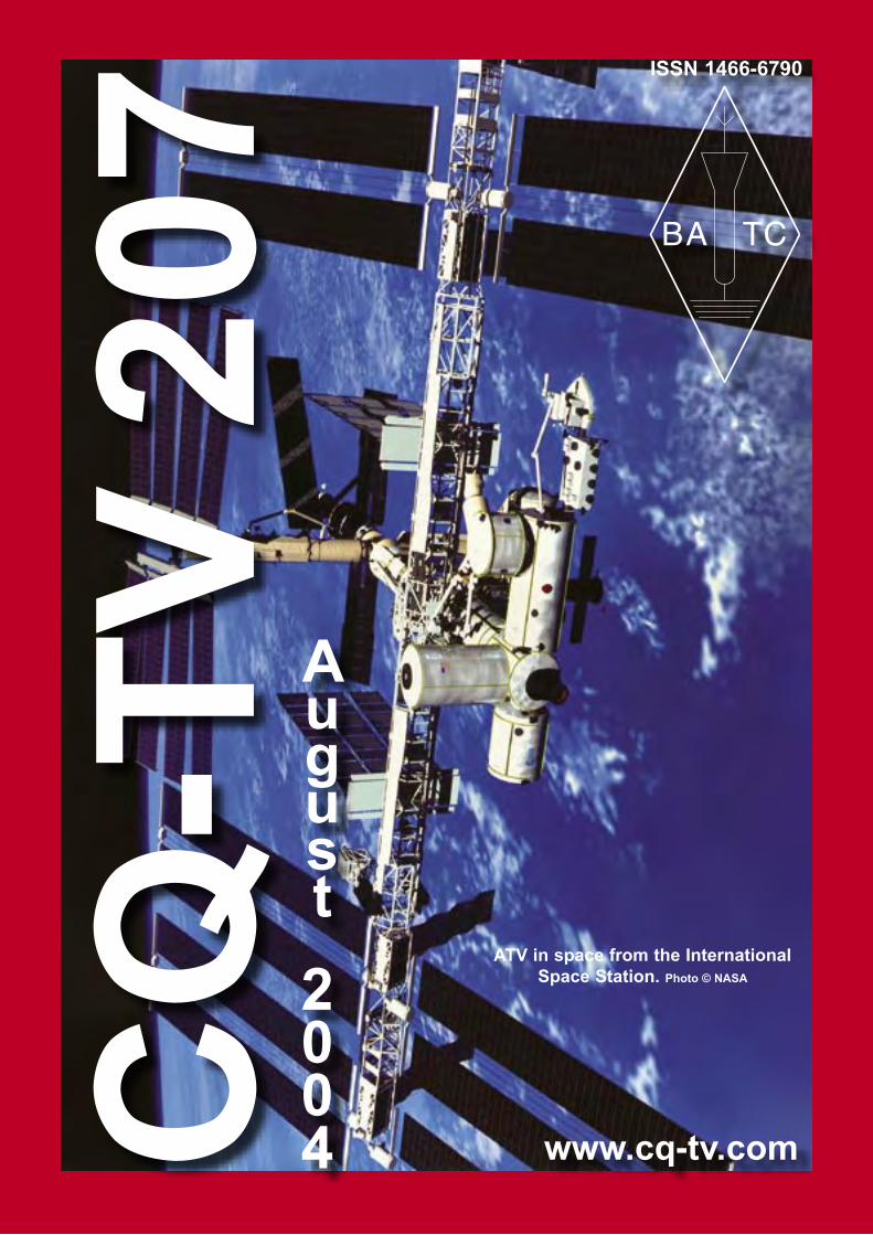
ATV in space from the International Space Station. Photo © NASA
www.cq-tv.com

Page 2 CQ-TV 207 - August 2004 Copyright © by the BATC
BlackBoxCamera™ Company LimitedThe STVKBD unit allows control of the STV5730A’s functionality from a PC keyboard. For full details of the unit’s operation please see the documentation.
This unit features the ability to construct scrolling video text overlays from text typed on each of the units four available screen pages. Each message can be upto 308 characters long. Text, and the scrolling feature, are stored when the unit is switched off and scrolling will restart when power is restored. The unit uses the standard UK keyboard key mapping, see the documentation. There is no facility to change to the keyboard mappings of other countries.
The unit is housed in a smart ABS plastic enclosure with phono connectors for video in / out, a 2.1mm DC power socket and a 9V PP3 battery clip. It is designed to be powered from the same power supply as the camera and so the unit does not have a power switch. Keyboard connection is via a 6-pin mini DIN socket for a PS/2 keyboard.
►Compatible with colour and mono composite video signals. 1Vp-p. PAL or NTSC* ►Dimensions 110 x 65 x 28mm LxWxH ►Power supply 9 - 12dc via on board regulator or 9V PP3 backup battery ►Power consumption 50mA (without keyboard)
*By default the unit will be supplied compatible with the video standard of the country from which you make your order.
If you require further information please contact us: [email protected]
Visit our web site at - www.stv5730a.co.uk
Copyright © by the BATC CQ-TV 207 - August 2004 Page 3
Copyright © by the BATC and contributors.Legal Niceties (the small print)E&OE. Whilst every care is taken in the production of this publication, the editor accepts no legal responsibility for the advice, data and opinions expressed. The BATC neither endorses nor is it responsible for the content of advertisements or the activities of those advertisers. No guarantee of accuracy is implied or given for the material herein. The BATC expressly disclaims all liability to any person in respect of anything and in respect of the consequences of anything done or omitted to be done wholly or partly in reliance upon the whole or any part of this magazine.As the regulations for the operation of radio frequency equipment vary in different countries, readers are advised to check that building or operating any piece of equipment described in CQ-TV will not contravene the rules that apply in their own country.The contents of this publication are covered by international copyright and must not be reproduced without permission, although an exception is made for not-for-profit publications (only) wishing to reprint short extracts or single articles and then only if acknowledgment is given to CQ-TV.Apart from any fair dealing for the purposes of published review, private study or research permitted under applicable copyright legislation, no part of this publication may be repro-duced, stored in a retrieval system or transmitted in any form or by any means, electronic, mechanical, photocopy, recording or otherwise, without the prior permission of the pub-lisher. All copyrights and trademarks mentioned in this publication are acknowledged and no infringement of the intellectual copyright of others is intended. Printed in Great Britain. ISSN 1466-6790
Notice to ContributorsAuthors are alone responsible for the content of their articles, including factual and legal accuracy, and opinions expressed by them may not reflect the editorial stance of the publica-tion. Material submitted to CQ-TV should not infringe the copyright of other writers or bod-ies. Articles remain the copyright of their authors and following publication in CQ-TV, they may also appear on the BATC’s web site and CD-ROMs, also in other not-for-profit amateur publications. Contributions are accepted for publication on this basis alone.
Printed by Clipper Print Ltd., Unit 13, East Goscote Ind. Estate, East Goscote, Leicester, LE7 3XJ, England. Telephone: 0116 260 9909.
An SDI Routing Switcher ......................................................................................8ATV from Space ..................................................................................................32A non-mechanical NBTV monitor - update ........................................................34BATC Publications ..............................................................................................33Chairman’s Column ...............................................................................................5Committee Contacts ...............................................................................................4Constitutional Amendments .................................................................................36Contents .................................................................................................................3Contest News .......................................................................................................36CQ-TV Commercial Advertising Rates ...............................................................46Deadlines ..............................................................................................................46Electronic CQ-TV ................................................................................................46Index of Advertisers .............................................................................................46In the Edit Suite ...................................................................................................20It’s all in Toronto .................................................................................................12Light Reading ......................................................................................................16Members’ Services ...............................................................................................33Minutes of the BATC BGM, 2004 ......................................................................30RF level video inserter .........................................................................................38Subscription Rates ...............................................................................................15The Early Television Foundation’s Annual Convention 2004 ............................26Turning Back the Pages .......................................................................................14TV or not TV? .....................................................................................................44Video Basics ........................................................................................................39What’s wrong with Analogue Satellite Receivers for ATV? ...............................37
Contents
CQ
-TV
207

Page 4 CQ-TV 207 - August 2004 Copyright © by the BATC
President: Mike Cox, CEng., FIEEE-mail: [email protected]
Chairman: Trevor Brown, G8CJSClub affairs, Videotape library, and Technical queries, especially relating to handbook projects. 14 Stairfoot Close, Adel, Leeds, LS16 8JR. Tel: 01132 670115. E-mail: [email protected]
General Secretary: Paul Marshall, G8MJWGeneral club correspondence and business. Library queries relating to the borrowing or donation of written material. Fern House, Church Road, Harby, Notts., NG23 7ED. Tel: 01522 703348. Email [email protected]
Hon. Treasurer: Brian Summers, G8GQSEnquiries regarding club finances, Donations, and constitutional enquiries. 9 Prior Croft Close, Camberley, Surrey, GU15 1DE. Tel: 01276 677879, Mobile077 4029 1191, Email: [email protected]
MembershipAnything to do with membership, including new applications, queries about new and existing membership, non-receipt of CQ-TV, subscriptions, membership records etc. Pat Hellen, The Villa, Plas Panteidal, Aberdyfi, Gwynedd, LL35 0RF, UK. Telephone 01654 767702. E-mail: [email protected]
Club Liaison: - And anything of a political nature, co-ordination of ATV repeater licences. Graham Shirville, G3VZV, The Hill Farm, Potsgrove, Milton Keynes, Bucks., MK17 9HF. Tel: 01525 290343. E-mail [email protected]
Contests: - Richard Parkes, G7MFO, 7 Main Street, Preston, Hull, HU12 8UB. Tel: 01482 898559. Email: [email protected]
CQ-TV Magazine: Editor Ian PawsonAnything for publication in CQ-TV, Articles, Review items, Letters to the editor, and other material except as below. 14 Lilac Avenue, Leicester, LE5 1FN, England. Tel: 0116 276 9425, Email: [email protected]
Photographs for the CQ-TV covers: - Please send any photographs by post, electronic images by email, to the editor at the above addresses.
TV on the Air: - Graham Hankins G8EMX, 17 Cottesbrook Road, Acocks Green, Birmingham, B27 6LE. Tel: 0121 706 7384
Satellite TV News: - Paul Holland G3TZO, Chatterton, Chapel Lane, Threapwood, Nr. Malpas, Cheshire, SY14 7AX. Tel: 01948 770429, Email: [email protected]
CQ-TV Advertising Manager: - Trevor Brown, 14 Stairfoot Close, Adel, Leeds, LS16 8JR. Tel: 01132 670115. Email: [email protected] Members adverts for inclusion in CQ-TV should be sent directly to the editor and the above address, either by post or e-mail.
CQ-TV Awards: - Bob Webb G8VBA, 78 Station Road, Rolleston on Dove, Burton on Trent, Staffs., DE13 9AB. Tel: 01283 814582
ExhibitionsGraham Hankins G8EMX, 17 Cottesbrook Road, Acocks Green, Birmingham, B27 6LE.Tel: 0121 706 7384 Email: [email protected]
Club SalesMembers Services: - PCB’s, components, camera tubes, accessories, etc. (NOT PUBLICATIONS). Peter Delaney, G8KZG, 6 East View Close, Wargrave, Berkshire, RG10 8BJ. Tel: 0118 940 3121. Email: [email protected]
Publications: - Handbooks, Back copies CQ-TV, and anything related to the supply of BATC publications. Paul Marshall, Fern House, Church Road, Harby, Notts., NG23 7ED, England. E-mail: [email protected]
CQ-TV and BATC web mastersAnything to do with the CQ-TV web site Email: [email protected] or for the BATCs web site. E-mail: [email protected]
Committee Contacts
Copyright © by the BATC CQ-TV 207 - August 2004 Page 5
By Trevor Brown
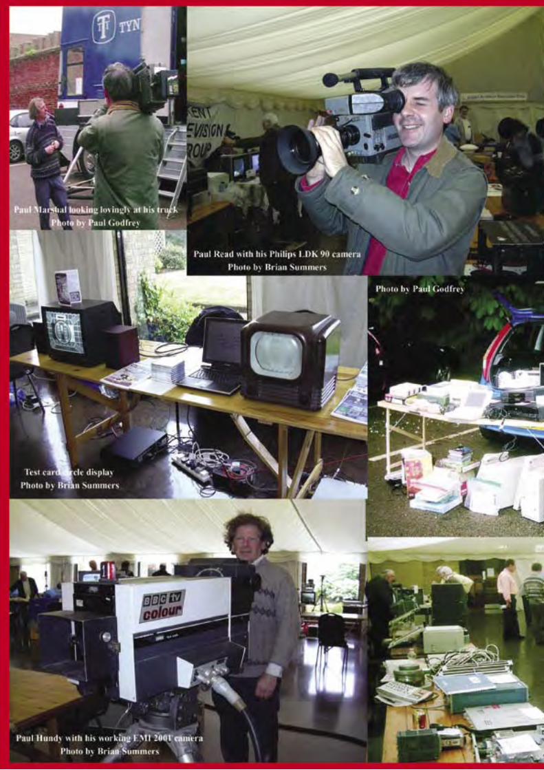
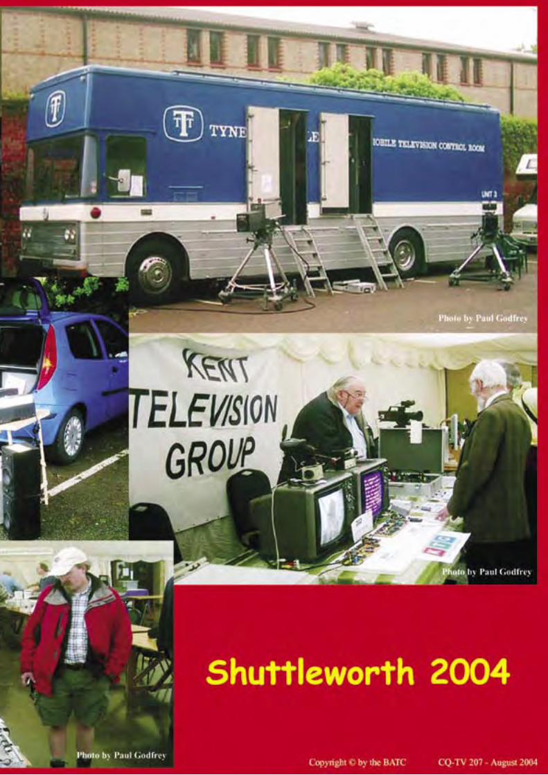
Shuttleworth was again the venue for the BGM. Paul Marshall treated us to a trip around his
latest acquisition, the ex Yorkshire TV scanner, now painted in Tyne Tees colours. Paul Hundy brought along his EMI 2001 camera and Mike Cox set up the completed SDI vision mixer for inspection. The lecture hall was the centre of activity, although I must confess to counting the attendees, and the peak was 51. The lectures covered DATV with practical demonstrations of both commercial kit and the AGAF modules. My thanks to Ian Waters, Noel Matthews and Dave Crump, not forgetting Oliver Crump who helped man one of the video cameras along with Paul Pitts. Graham Shirville took us through a plan for ATV on the ARISS (space station) and Carlos Eavis enlightened us on the politics of post 911 70 cms and the reversal of the decline in MOD activity on this band. Mike Cox weighed in with the history of IBC. It was hoped that this varied lecture programme would appeal to all sections of the club, and the response has cast doubt on the future viability of this venue, which will seat 200+. On the brighter side, Brian Kelly video taped the lectures and I now have a complete set of DVD’s on my desk. Graham’s lecture has already seen the light of day on Ben Jocket’s satellite
transmission. I was hoping to make the DVD’s down loadable from the website, but at the moment the site has its own space problem. It is nothing that can’t be fixed by funding and is a bullet we may soon have to bite.
Ian Pawson was presented with the Grant Dixon award for his contribution to CQ-TV. I don’t think anyone would disagree that Ian has put a lot of effort into the magazine, and without him neither the club or the magazine would be where it is today. Paul Marshall collected the award in Ian’s absence. The BGM lasted for a record two hours - mainly questions on the club’s future. Although this is not really the forum for brain storming, it was pleasant to see this concern over the clubs future.
We have, I believe, reached a point where ‘no change’ is not an option. To this end, I have my own personal view on the direction we should go, and that is a membership cost of around £2 per annum and CQ-TV delivered in colour via the internet. Printing magazines is a big boys game and we are increasingly being bitten by the fixed cost of small print runs. We have already seen the Dutch ATV magazine “Repeater” shut up shop. We would need a circulation of 20,000 plus to produce a full colour magazine at supermarket shelf prices. This is not gong to be possible, and if we adopt the ‘no change’ attitude, then we will see print prices pushing up club subscriptions and the membership numbers falling. An income of £2000 and no printing costs would more than cover the cost of an expanded
website - one that would give us all a BATC domain email address and room to webstream some of our programme library. Our administration cost could be covered, and similarly the BGM or annual meeting.
The AGAF are continuing with their DATV initative. Phase one of the hardware is running and at Friedrichshafen they plan to show what this DATV kit can do - this time from a boat to a hill in Austria on 13 cm and from the hill top to the AGAF booth on 23 cm.
Chairman’s Column
G. Dixon
The Editor.
Page 6 CQ-TV 207 - August 2004 Copyright © by the BATC
Help Needed for Repeater in Ireland
By Mark, EI9IB
Mark EI9IB is working on an Amateur Television repeater for Kildare which is a county
west of Dublin City in the Republic of Ireland. With the 24cm band being only 1240 to 1300Mhz in the republic this means that most repaters have and input around 1249Mhz and outputs around 1275Mhz.
The repeater licence states input on 1249Mhz and output on 1280Mhz. This is only a 31Mhz difference which causes a problem making suitable filters.
Most UK ATV repeaters use 50Mhz or more seperation. A 5 or more pole interdigital filter is needed for correct operation. In other ATV sites in Ireland correct filtering was achieved by greatly seperating the transmit and receive aerials. In one case the aerials are a mile apart on different sites linked by 10GHz. This is not possible at this site.
The repeater is in beacon mode at the moment using the callsign EI4KVR
until suitable filters can be made/bought. Current attempts to make filters of the quality required have failed. If any readers can help by making filters, or know someone who can, please contact Mark EI9IB by email [email protected] or by telephone to 00-353-866013392
Some photos of proposed test card etc for the article are here: http://www.hi2all.com/ei4kvr_24cm_atv_repeater_page.htm
DATV newsJust before Christmas 2003 some first DATV units were completed and tested by hams and students lead by Uwe, DJ8DW, at the Wuppertal University and then delivered to orderers according to the listing. Meanwhile more than 80 sets have reached the “digital elite”. Hans, PA0HKS, performed some contacts with one of the new units in the Netherlands, to Germany and to Belgium, using a prototype up-converter 70/23 cm from Wuppertal and a 30 Watt PA with very linear 2C39 valves.
Earlier the university club station DL0DTV had done an OFDM test (DVB-T) on 23 cm with 4 Watt into a 10 dB omni slot antenna. Receiving unit was a DVB-T Set-Top Box with down converter and loop dipole, pictures were good in spite of strong reflections between the mountains. An additional DATV TX board for OFDM modulation is in preparation, especially advisable for DATV repeater outputs above 1 GHz with multiple reflections in the surrounding area.
(translation Klaus, DL4KCK)
Dicky Howett writes,
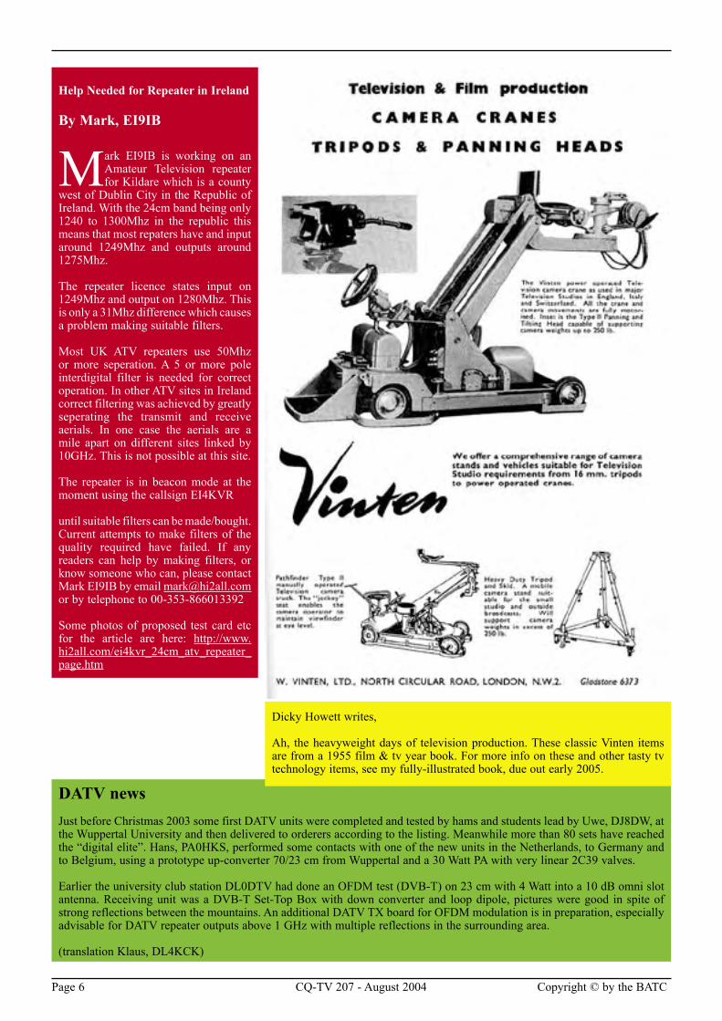
Ah, the heavyweight days of television production. These classic Vinten items are from a 1955 film & tv year book. For more info on these and other tasty tv technology items, see my fully-illustrated book, due out early 2005.
Copyright © by the BATC CQ-TV 207 - August 2004 Page 7
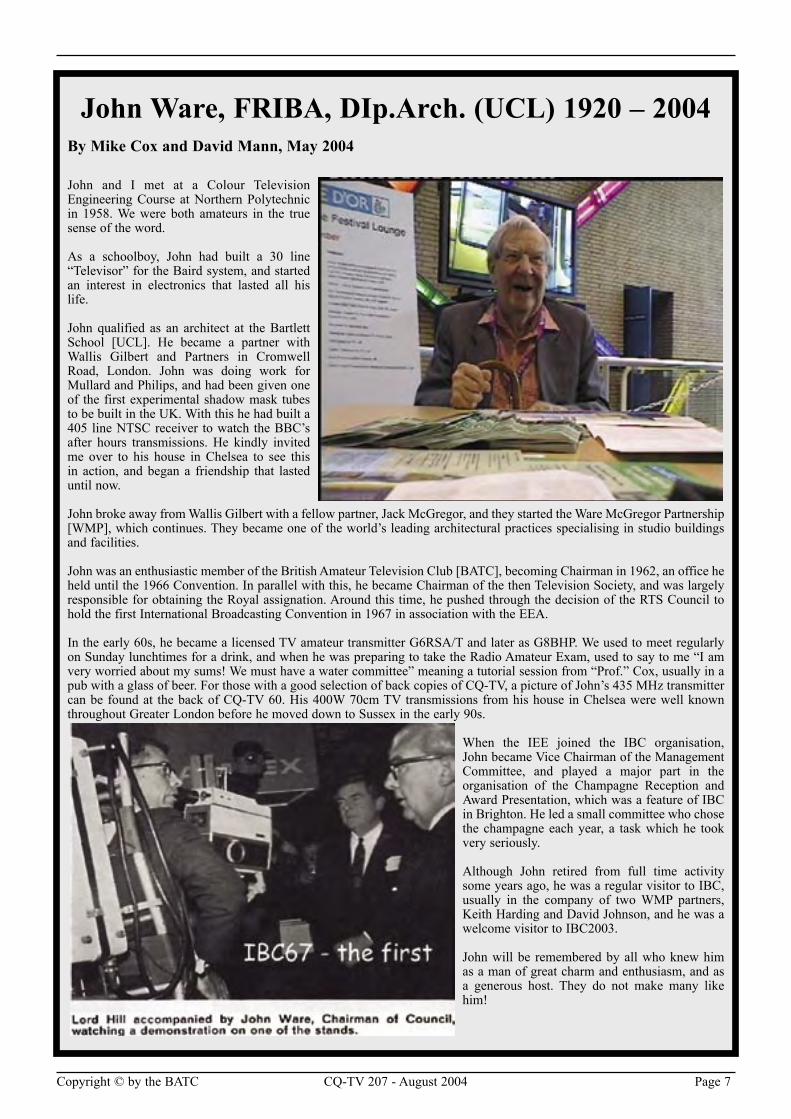
John Ware, FRIBA, DIp.Arch. (UCL) 1920 – 2004By Mike Cox and David Mann, May 2004
John and I met at a Colour Television Engineering Course at Northern Polytechnic in 1958. We were both amateurs in the true sense of the word.
As a schoolboy, John had built a 30 line “Televisor” for the Baird system, and started an interest in electronics that lasted all his life.
John qualified as an architect at the Bartlett School [UCL]. He became a partner with Wallis Gilbert and Partners in Cromwell Road, London. John was doing work for Mullard and Philips, and had been given one of the first experimental shadow mask tubes to be built in the UK. With this he had built a 405 line NTSC receiver to watch the BBC’s after hours transmissions. He kindly invited me over to his house in Chelsea to see this in action, and began a friendship that lasted until now.
John broke away from Wallis Gilbert with a fellow partner, Jack McGregor, and they started the Ware McGregor Partnership [WMP], which continues. They became one of the world’s leading architectural practices specialising in studio buildings and facilities.
John was an enthusiastic member of the British Amateur Television Club [BATC], becoming Chairman in 1962, an office he held until the 1966 Convention. In parallel with this, he became Chairman of the then Television Society, and was largely responsible for obtaining the Royal assignation. Around this time, he pushed through the decision of the RTS Council to hold the first International Broadcasting Convention in 1967 in association with the EEA.
In the early 60s, he became a licensed TV amateur transmitter G6RSA/T and later as G8BHP. We used to meet regularly on Sunday lunchtimes for a drink, and when he was preparing to take the Radio Amateur Exam, used to say to me “I am very worried about my sums! We must have a water committee” meaning a tutorial session from “Prof.” Cox, usually in a pub with a glass of beer. For those with a good selection of back copies of CQ-TV, a picture of John’s 435 MHz transmitter can be found at the back of CQ-TV 60. His 400W 70cm TV transmissions from his house in Chelsea were well known throughout Greater London before he moved down to Sussex in the early 90s.
When the IEE joined the IBC organisation, John became Vice Chairman of the Management Committee, and played a major part in the organisation of the Champagne Reception and Award Presentation, which was a feature of IBC in Brighton. He led a small committee who chose the champagne each year, a task which he took very seriously.
Although John retired from full time activity some years ago, he was a regular visitor to IBC, usually in the company of two WMP partners, Keith Harding and David Johnson, and he was a welcome visitor to IBC2003.
John will be remembered by all who knew him as a man of great charm and enthusiasm, and as a generous host. They do not make many like him!
Page 8 CQ-TV 207 - August 2004 Copyright © by the BATC
By Mike Cox
Introduction
In CQ-TV 205, the problem of losing audio embedded in the SDI stream was mentioned, and was because
of the switching technique used in the 841SDI mixer. You will recall that the input SDI signals were de-serialised as soon as they arrived at the mixer inputs. The consequent switching and processing in the CCIR601 domain effectively removed any ancillary signals such as audio or data.
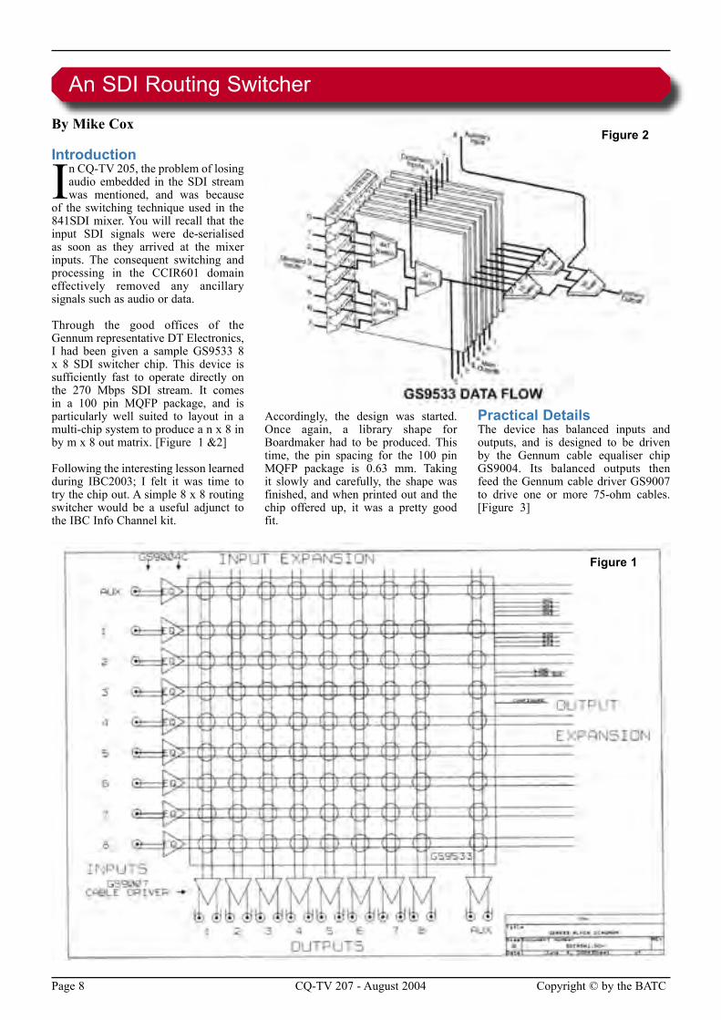
Through the good offices of the Gennum representative DT Electronics, I had been given a sample GS9533 8 x 8 SDI switcher chip. This device is sufficiently fast to operate directly on the 270 Mbps SDI stream. It comes in a 100 pin MQFP package, and is particularly well suited to layout in a multi-chip system to produce a n x 8 in by m x 8 out matrix. [Figure 1 &2]
Following the interesting lesson learned during IBC2003; I felt it was time to try the chip out. A simple 8 x 8 routing switcher would be a useful adjunct to the IBC Info Channel kit.
Accordingly, the design was started. Once again, a library shape for Boardmaker had to be produced. This time, the pin spacing for the 100 pin MQFP package is 0.63 mm. Taking it slowly and carefully, the shape was finished, and when printed out and the chip offered up, it was a pretty good fit.
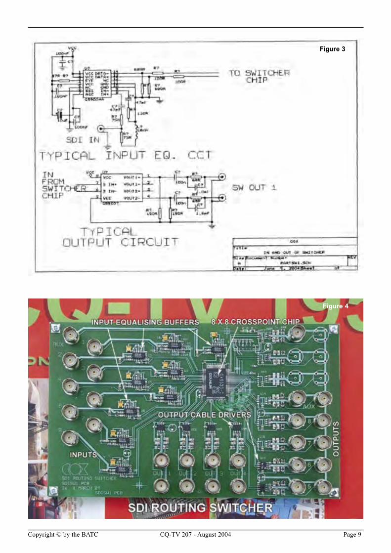
Practical DetailsThe device has balanced inputs and outputs, and is designed to be driven by the Gennum cable equaliser chip GS9004. Its balanced outputs then feed the Gennum cable driver GS9007 to drive one or more 75-ohm cables. [Figure 3]
An SDI Routing Switcher
Figure 2
Figure 1
Copyright © by the BATC CQ-TV 207 - August 2004 Page 9
Figure 3
Figure 4
Page 10 CQ-TV 207 - August 2004 Copyright © by the BATC
As an aside, if you want to make a simple cable equaliser for SDI, connect the output lines of the GS9004 [in Figure 3] to the inputs of the GS9007 and you have an equaliser for up to 300 metres of good quality 75 ohm cable such as PSF1/2, BICC T3205 or Belden 8281 [ or shorter runs of poorer quality cable].
In this case, it was decided that 2 feeds of each output would be sufficient.
It was also decided that the switcher would be built on a pc board with upright BNCs so that it could be mounted directly on a rack panel with next to no depth. The whole unit replicates a patch
panel, and that it how it will be used. [Figure 4]
The GS9533 is specified up to 622 Mbps, so is more than adequate for 270 [or 360 Mbps] Mbps Standard definition SDI. When set for driving 800 mV into the cable driver, it consumes around 150 mA at 5 volts. As it is a small chip, it gets quite warm. The whole switcher consumes just under 1A, so a small switch mode supply will power it.
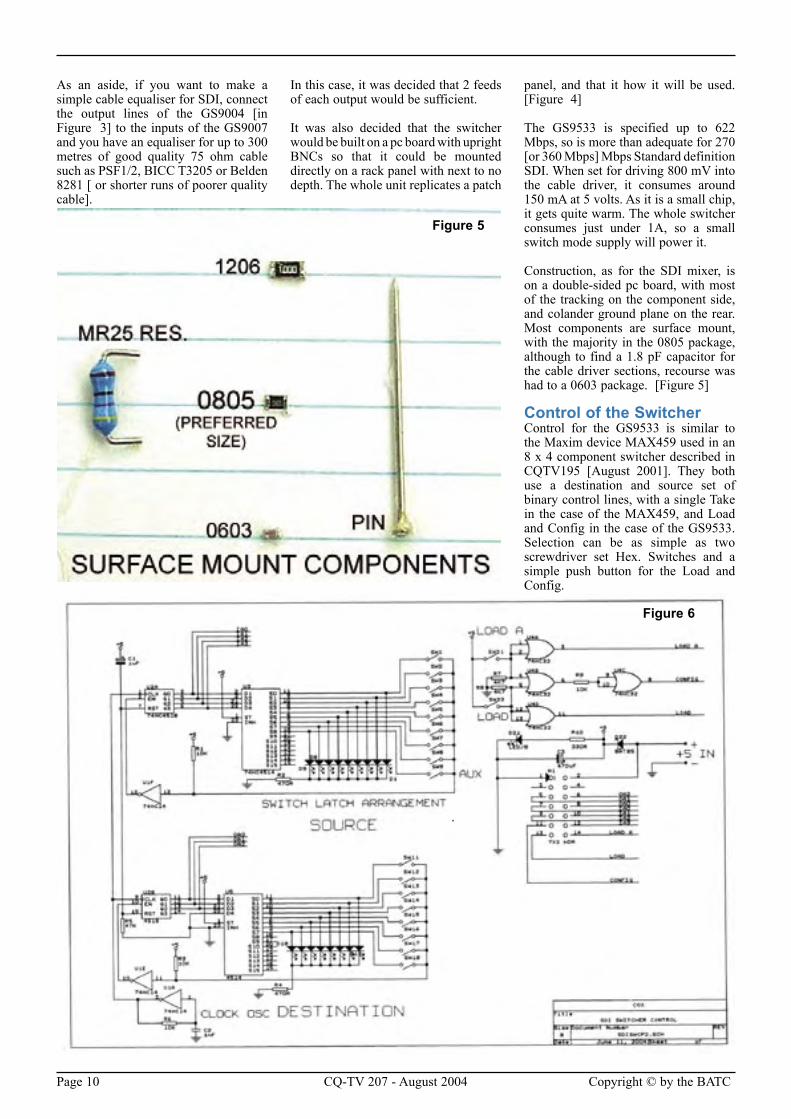
Construction, as for the SDI mixer, is on a double-sided pc board, with most of the tracking on the component side, and colander ground plane on the rear. Most components are surface mount, with the majority in the 0805 package, although to find a 1.8 pF capacitor for the cable driver sections, recourse was had to a 0603 package. [Figure 5]
Control of the SwitcherControl for the GS9533 is similar to the Maxim device MAX459 used in an 8 x 4 component switcher described in CQTV195 [August 2001]. They both use a destination and source set of binary control lines, with a single Take in the case of the MAX459, and Load and Config in the case of the GS9533. Selection can be as simple as two screwdriver set Hex. Switches and a simple push button for the Load and Config.
Figure 5
Figure 6
Copyright © by the BATC CQ-TV 207 - August 2004 Page 11
As the unit is a routing switcher, no account is taken of the vertical interval. Switching occurs in a random manner. However, it would be simple to latch the Load and ConFigure Commands with a vertical interval pulse, if it is needed.
However, as the final device will be rack mountable, push buttons and electronic latches are to be mounted at the right hand side of the panel. [Figure 6]
TestingTesting such a switcher requires a number of feeds and monitoring destinations, otherwise much time will be spent plugging cables in and out to fully explore the 64 or so crosspoints. The input equalisers should be capable of equalising a cable run of around 300 meters. There is a simple way to derive two feeds from a single source – a 75-ohm splitter network. Three 75-ohm resistors in a delta arrangement,
or three 25-ohm resistors in a star arrangement will effectively split a feed into two, with a 6 dB loss to each output. However, the GS9004 input equaliser will cope with this happily.
If no genuine SDI feeds are to hand, an RF generator capable of delivering 0 dBm into 75 ohms can be used to check performance. Up to 50 MHz, the output will look roughly square, with around 800 mV pk – pk output. Note that the oscilloscope used needs a bandwidth of 200+ MHz to give a half way accurate indication of a 50 MHz square wave. At 100 MHz input, my oscilloscope gave a sine wave of around 800 mV, but then its bandwidth is only 100 MHz. Reduce the input level until the output becomes noisy; this gives the clipping threshold. Note that as the input frequency is increased from say 20 MHz to 80 MHz, the clipping threshold gets lower by about 14 dB, demonstrating the equaliser action. This
is roughly the inverse of the cable loss at these frequencies.
Crosstalk in such a switcher shows up as edge jitter. Care has to be taken as in any switcher that return signal currents from cable are routed away from other return paths.
Good RF layout practice is called for.
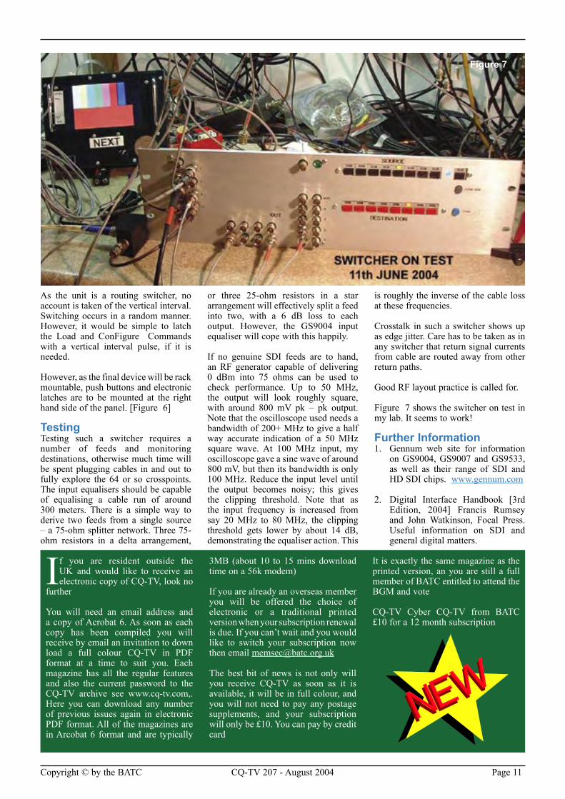
Figure 7 shows the switcher on test in my lab. It seems to work!
Further Information1. Gennum web site for information
on GS9004, GS9007 and GS9533, as well as their range of SDI and HD SDI chips. www.gennum.com
2. Digital Interface Handbook [3rd Edition, 2004] Francis Rumsey and John Watkinson, Focal Press. Useful information on SDI and general digital matters.
Figure 7
If you are resident outside the UK and would like to receive an electronic copy of CQ-TV, look no
further
You will need an email address and a copy of Acrobat 6. As soon as each copy has been compiled you will receive by email an invitation to down load a full colour CQ-TV in PDF format at a time to suit you. Each magazine has all the regular features and also the current password to the CQ-TV archive see www.cq-tv.com,. Here you can download any number of previous issues again in electronic PDF format. All of the magazines are in Arcobat 6 format and are typically
3MB (about 10 to 15 mins download time on a 56k modem)
If you are already an overseas member you will be offered the choice of electronic or a traditional printed version when your subscription renewal is due. If you can’t wait and you would like to switch your subscription now then email [email protected]
The best bit of news is not only will you receive CQ-TV as soon as it is available, it will be in full colour, and you will not need to pay any postage supplements, and your subscription will only be £10. You can pay by credit card
It is exactly the same magazine as the printed version, an you are still a full member of BATC entitled to attend the BGM and vote
CQ-TV Cyber CQ-TV from BATC £10 for a 12 month subscription
Page 12 CQ-TV 207 - August 2004 Copyright © by the BATC
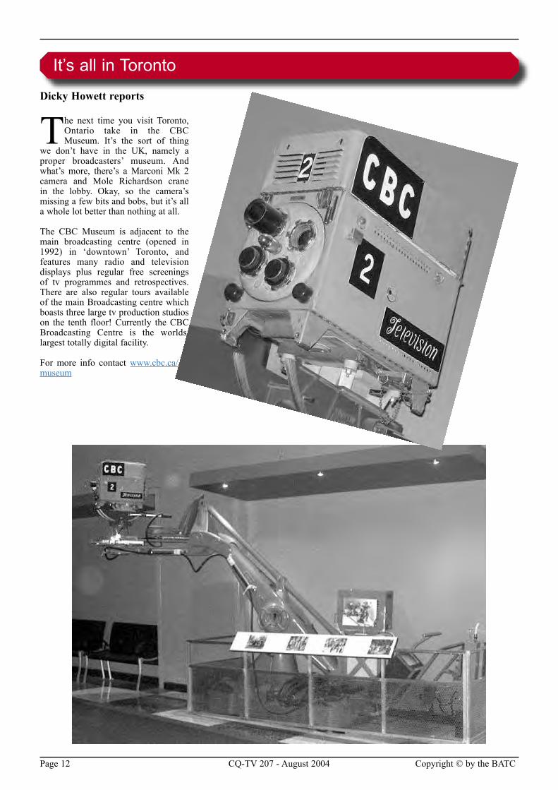
Dicky Howett reports
The next time you visit Toronto, Ontario take in the CBC Museum. It’s the sort of thing
we don’t have in the UK, namely a proper broadcasters’ museum. And what’s more, there’s a Marconi Mk 2 camera and Mole Richardson crane in the lobby. Okay, so the camera’s missing a few bits and bobs, but it’s all a whole lot better than nothing at all.
The CBC Museum is adjacent to the main broadcasting centre (opened in 1992) in ‘downtown’ Toronto, and features many radio and television displays plus regular free screenings of tv programmes and retrospectives. There are also regular tours available of the main Broadcasting centre which boasts three large tv production studios on the tenth floor! Currently the CBC Broadcasting Centre is the worlds largest totally digital facility.
For more info contact www.cbc.ca/museum
It’s all in Toronto

Copyright © by the BATC CQ-TV 207 - August 2004 Page 13
Severnside Television GroupOur 23cms antennas are specifically designed for ATV use although they can be used for other modes as well. Their wideband characteristics mean you only need one antenna to cover repeater input and output channels. Our famous wideband Yagis come fully assembled in two versions:
38-ELEMENT HIGH GAIN: 14db gain, 1.8m long, £28.50 plus P&P
18-ELEMENT STANDARD: 10db gain, 0.9m long, £15.00 plus P&P
Don’t forget our
20-ELEMENT CONVERSION KIT, which converts our 18-element antenna to the full 38-element high-gain specification. £15.00 plus P&P
Our antennas feature an SWR better than 1.5:1 and are supplied with clamps for masts up to 55mm diameter
Connections are by screw terminals in a weather resistant box – mast, cable and connectors are not provided. A more detailed specification can be found on our web site www.stvg.co.uk on the ‘our products’ page.
Postage and packing is £5.00 per item to UK addresses only (unless by prior arrangement).
Sterling Cheques or bankers drafts payable to “Severnside Television Group” should be sent to:
STG (ref. CQ-TV). 3 Beechwood Drive, Penarth, Vale of Glamorgan, CF64 3RB
G6NHG10GHz Horn polyester coated mild steel (20 dB) . . . . . . . . .£2510GHz Horn Stainless Steel (20dB) . . . . . . . . . . . . . . . . . . .£322.4GHz spun aluminium Horn (14dB) with mast mounting bracket. . . . . . . . . . . . . . . . . . . . . . . . . . . . . . . . . . . . . . . . . .£301.3GHz Alford Slot . . . . . . . . . . . . . . . . . . . . . . . . . . . . . . . .£602.4GHz Alford Slot . . . . . . . . . . . . . . . . . . . . . . . . . . . . . . . .£55Weather proof covers for Alford Slots. . . . . . . . . . . . . . . . . .£12SMA to WG16 Feeds. . . . . . . . . . . . . . . . . . . . . . . . . . . . . . .£23WG 16 Flanges . . . . . . . . . . . . . . . . . . . . . . . . . . . . . . . . . . . .£6WG16 to WG17 adapters. . . . . . . . . . . . . . . . . . . . . . . . . . . . .£53cms slot antennas from . . . . . . . . . . . . . . . . . . . . . . . . . . . .£753cms filters from . . . . . . . . . . . . . . . . . . . . . . . . . . . . . . . . . .£60
For further information, contact:-S. Marshall, G6NHG,25 Carlcroft,Stonydelph,Tamworth,Staffs., B77 4DL.
Telephone 01827 897920. 7:30pm - 10pm weekdays.Email: [email protected]
HS Publications7 Epping Close, Derby, DE22 4HR.
Telephone: 01332 38 16 99Email: [email protected]
• DX-TV Converters
• VHF-UHF TV Aerials
• DX-TV Publications and Videos
• Amplifers - Filters - Hardware
• Technical Books
• BBC Test Card music CDs
• TV Clocks and Archive Publications
Send 3 First Class stamps for our latest catalogue Personal callers by prior arrangement only please
Visit our web site - www.cq-tv.com
Page 14 CQ-TV 207 - August 2004 Copyright © by the BATC
By Peter Delaney
A dip into the archives of CQ-TV, looking at the issue of 50 years ago.
CQ-TV 21 - June 1954
The cover took the form of a basic test card.
“This is our 21st edition, and we may be said to have come of age. When the first edition came out in October 1949, no-one, least of all your Editor, thought we would run to 21 editions. It seems we must be filling a long felt want, so we are celebrating with a slightly larger edition than usual; since this is even more expensive, a special word of thanks is due to those members who have generously added something to their subscriptions”.
“Details of the new Amateur Television Transmitting Licence are now available from the Radio and Accommodation Dept, GPO St Martins le Grand, London EC1. The cost is £2 per annum, and abridged details are given below. The licensee is licensed to send (i) Vision signals; (ii) the callsign of the station by cw, mcw or phone; and (iii) to receive signals and messages from other amateur stations by any means.” “ A log, including the subject of transmission, shall be kept, and a receiver must be available on the transmission frequency”. “ Considering one or two
points in detail, it will be seen that no sound channel has been allocated (unless a sound licence is held), and only the callsign may be sent “ soundwise” . Just how this will work in practice remains to be seen ...” . “Present regulations state that the normal G3+3 callsigns will be issued, /T; there is to be no reduction in cost if the sound license is already held, since for some reason A5 and F5 modulation is considered something very special”
“Shorter Notes” on page 3 included “Prize offered for first simple reliable 70cm tv transmitter design using easily obtained and not too expensive valves”, whilst on page 12, members were invited to think about designing “a 70cm tv tx using a minimum number of
easily found valves. Need not be crystal controlled ... Keep the price below £5 if you can”.
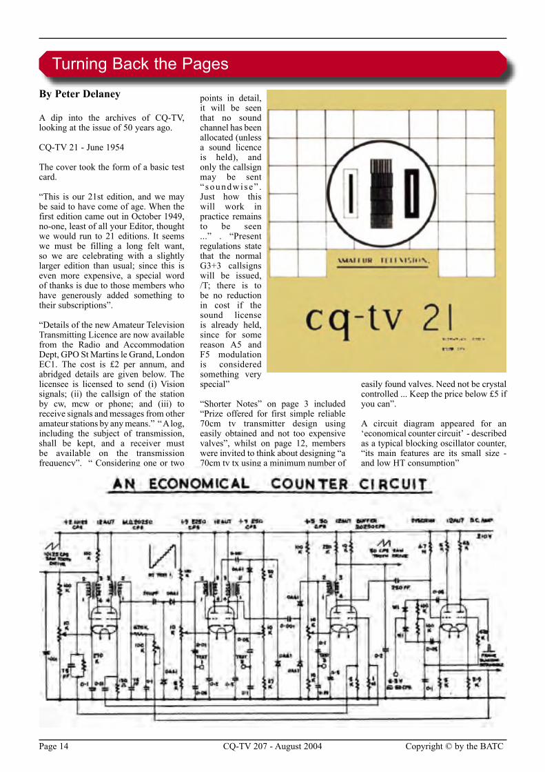
A circuit diagram appeared for an ‘economical counter circuit’ - described as a typical blocking oscillator counter, “its main features are its small size - and low HT consumption”
Turning Back the Pages
Copyright © by the BATC CQ-TV 207 - August 2004 Page 15
Subscription Rates
Years Surface Airmail
One £15.00 £21.00
Two £29.00 £41.00
Three £43.00 £61.00
Cyber £10.00 £10.00
Please note that the surface rate covers postage within the Europe, airmail rate is NOT required
If your subscription is due before the next issue of CQ-TV, you will soon be receiving a letter containg a personalised renewal form.
We hope that you will continue to support the Club and we look forward to receiving your renewal by post or via our web site.
Cyber membership is currently only available to members outside the UK. Cyber member will not receive a paper copy of CQ-TV, but will be able to download the electronic (pdf) version. Please note that these files require the Adobe Acrobat reader version 6 or above.
Page 16 CQ-TV 207 - August 2004 Copyright © by the BATC
By Ron L. Sparks
Recently I was looking at cameras to install for security purposes around my place, and realized
that I had forgotten a lot of what I once knew about light and measurements of light. There is a famous saying that goes something like, “Knowledge (or Education) is what is left after you have forgotten everything you learned.” So it had not really become knowledge for me. By the way, you will often find that quote attributed, with an attached reference to Einstein, most probably incorrectly. The most likely source is William Feather1. But I digress. I went and dug out some old work I did, along with some reference material and began to reinstate the knowledge. After doing that I began thinking about what we generally need to do.
As ATVers we are primarily interested in camera specifications and available lighting. Unfortunately, the measurements for these two items are completely different. It is definitely an “apples and oranges” comparison. I will explain why and what to do about it in a little bit. But first I need to warn you about the specifications themselves. Most of the camera makers have got into a “specifications war” ,much like the power output numbers audio equipment manufacturers put out in the ’70s – purposely confusing measurement methods in order to win the battle of the best specs for the least money. Fortunately the American National Standards Institute (ANSI) has published some standards that help a bit, but even now many of the manufacturers numbers should be considered as rough guidelines only.
From Candela to LuxOne of the first things we have to sort out about light measurements is the amazing array of units. For example, you will find light measured in candelas (and millicandelas), foot-candles, candlepower, lumens, phots, lux, steradians, lamberts, and several others. As if that was not bad enough, when you start trying to convert one to another you will find out that, in some cases, it cannot be done. The reason usually has to do with the nature of light and the ways to measure it. In order to sort things out a bit, let us consider how light can be measured.
First, it can be measured as it is radiated out into space. This is technically called total flux and is analogous to the output power of your transmitter. The second way it can be measured is by the amount of light that strikes a given object. This is called illuminance and is similar to the amount of signal that arrives at your location some distance away from a transmitter. The third way that light is measured is called luminance and is the amount of light that reaches your eye or camera after reflecting off a surface. Since luminance and illuminance are similar words with very different meanings I like to use the term visibility as a synonym to luminance. I also like to use the term intensity in place of total flux. That gives us three ways to measure light: intensity, illuminance, and visibility.
The units you will come across the most often are millicandela, candlepower, lumens, lux, and foot-candles. The first three are measures of intensity and the last two are measures of illuminance. That is why you cannot just convert the millicandela of an IR LED into the number of lux it produces for the camera. But, you can convert units of one type into units of the same type. For example, illuminance units can be converted into other units of illuminance. So since the lux and foot-candle are both illuminance measures
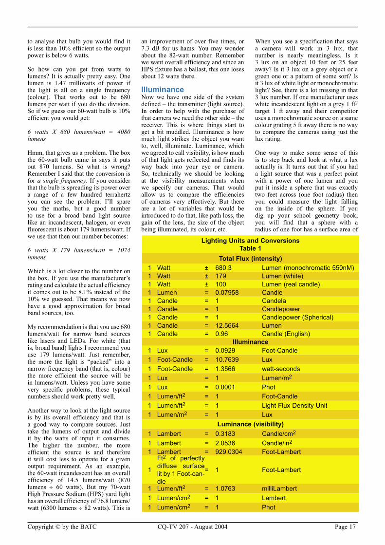
you can convert foot-candles to lux by multiplying by 10.24. I have made table 1 to allow you to perform this type of conversion. But, since we have candelas and lumens as measurements of our sources we need a method to calculate the illuminance they will create. As hams though, we have an advantage because we are used to power and power calculations. And after all, intensity is just a measure of power – right?
IntensityWell, sort of. Light intensity can certainly be measured in watts. Many lasers are specified in milliwatts or watts of output. But most of the time you will find light measured in candlepower or lumens. Why is the usual method more complicated you might wonder? It has to do with the spectrum of light generated. Many light sources are wideband, just as an ATV signal has its power distributed across a wide spectrum. You cannot easily relate the power of an ATV signal to a pure carrier’s power. That is why we generally specify a complex signal in terms of PEP or RMS power. That is exactly why light sources are not usually rated in watts of output. Be careful with that term. When you think about transmitters you automatically think of output power. When you think about a 60-watt bulb, though, you are thinking of input power. If you were
Light Reading
Copyright © by the BATC CQ-TV 207 - August 2004 Page 17
to analyse that bulb you would find it is less than 10% efficient so the output power is below 6 watts.
So how can you get from watts to lumens? It is actually pretty easy. One lumen is 1.47 milliwatts of power if the light is all on a single frequency (colour). That works out to be 680 lumens per watt if you do the division. So if we guess our 60-watt bulb is 10% efficient you would get:
6 watts X 680 lumens/watt = 4080 lumens
Hmm, that gives us a problem. The box the 60-watt bulb came in says it puts out 870 lumens. So what is wrong? Remember I said that the conversion is for a single frequency. If you consider that the bulb is spreading its power over a range of a few hundred terrahertz you can see the problem. I’ll spare you the maths, but a good number to use for a broad band light source like an incandescent, halogen, or even fluorescent is about 179 lumens/watt. If we use that then our number becomes:
6 watts X 179 lumens/watt = 1074 lumens
Which is a lot closer to the number on the box. If you use the manufacturer’s rating and calculate the actual efficiency it comes out to be 8.1% instead of the 10% we guessed. That means we now have a good approximation for broad band sources, too.
My recommendation is that you use 680 lumens/watt for narrow band sources like lasers and LEDs. For white (that is, broad band) lights I recommend you use 179 lumens/watt. Just remember, the more the light is “packed” into a narrow frequency band (that is, colour) the more efficient the source will be in lumens/watt. Unless you have some very specific problems, these typical numbers should work pretty well.
Another way to look at the light source is by its overall efficiency and that is a good way to compare sources. Just take the lumens of output and divide it by the watts of input it consumes. The higher the number, the more efficient the source is and therefore it will cost less to operate for a given output requirement. As an example, the 60-watt incandescent has an overall efficiency of 14.5 lumens/watt (870 lumens ÷ 60 watts). But my 70-watt High Pressure Sodium (HPS) yard light has an overall efficiency of 76.8 lumens/watt (6300 lumens ÷ 82 watts). This is
an improvement of over five times, or 7.3 dB for us hams. You may wonder about the 82-watt number. Remember we want overall efficiency and since an HPS fixture has a ballast, this one loses about 12 watts there.
IlluminanceNow we have one side of the system defined – the transmitter (light source). In order to help with the purchase of that camera we need the other side – the receiver. This is where things start to get a bit muddled. Illuminance is how much light strikes the object you want to, well, illuminate. Luminance, which we agreed to call visibility, is how much of that light gets reflected and finds its way back into your eye or camera. So, technically we should be looking at the visibility measurements when we specify our cameras. That would allow us to compare the efficiencies of cameras very effectively. But there are a lot of variables that would be introduced to do that, like path loss, the gain of the lens, the size of the object being illuminated, its colour, etc.
When you see a specification that says a camera will work in 3 lux, that number is nearly meaningless. Is it 3 lux on an object 10 feet or 25 feet away? Is it 3 lux on a grey object or a green one or a pattern of some sort? Is it 3 lux of white light or monochromatic light? See, there is a lot missing in that 3 lux number. If one manufacturer uses white incandescent light on a grey 1 ft2 target 1 ft away and their competitor uses a monochromatic source on a same colour grating 5 ft away there is no way to compare the cameras using just the lux rating.
One way to make some sense of this is to step back and look at what a lux actually is. It turns out that if you had a light source that was a perfect point with a power of one lumen and you put it inside a sphere that was exactly two feet across (one foot radius) then you could measure the light falling on the inside of the sphere. If you dig up your school geometry book, you will find that a sphere with a radius of one foot has a surface area of
Lighting Units and ConversionsTable 1
Total Flux (intensity)1 Watt ± 680.3 Lumen (monochromatic 550nM)1 Watt ± 179 Lumen (white)1 Watt ± 100 Lumen (real candle)1 Lumen = 0.07958 Candle1 Candle = 1 Candela1 Candle = 1 Candlepower1 Candle = 1 Candlepower (Spherical)1 Candle = 12.5664 Lumen1 Candle = 0.96 Candle (English)
Illuminance1 Lux = 0.0929 Foot-Candle1 Foot-Candle = 10.7639 Lux1 Foot-Candle = 1.3566 watt-seconds1 Lux = 1 Lumen/m2 1 Lux = 0.0001 Phot1 Lumen/ft2 = 1 Foot-Candle1 Lumen/ft2 = 1 Light Flux Density Unit1 Lumen/m2 = 1 Lux
Luminance (visibility)1 Lambert = 0.3183 Candle/cm2 1 Lambert = 2.0536 Candle/in2 1 Lambert = 929.0304 Foot-Lambert
1
Ft2 of perfectly diffuse surface lit by 1 Foot-can-dle
= 1 Foot-Lambert
1 Lumen/ft2 = 1.0763 milliLambert1 Lumen/cm2 = 1 Lambert1 Lumen/cm2 = 1 Phot
Page 18 CQ-TV 207 - August 2004 Copyright © by the BATC
4·π·r2 = 12.56 square feet. If you have worked with light measures much at all you will recognize that number. It is the conversion from candlepower to lumens. That is because the lumen was derived from the older candlepower measurement.
Here is where illuminance gets a little tricky. If you imagine that candle (or 12.56 lumen source) inside a one foot radius sphere the amount of light that falls on one square foot is said to be a certain number of lux. But if you make the sphere 10 foot radius, the same number of photons are covering a surface 100 times larger (radius squared, remember). So the number of lux will be 1/100th what it was in the smaller sphere. This is probably a good place to re-mention that one foot-candle is equal to 10.24 lux. But for many illumination designs you will see that simplified to just 10.
I will not bore you with the engineering, but here is a good rule of thumb. If the length and width of the source is less than one fourth the distance to the object being illuminated you can just use the square of the distance to estimate how much the illuminance changes. For example, if you measure the illumination on the ground 10 feet from your yard light to be 15 foot-candles (150 lux) then at 100 feet it would be:
15 X (102 ÷ 1002) = 0.0015 ft-cd = 0.015 lux
Which is pretty dim. That is just below moonlight and in the range of starlight. If you want to look at typical illumination levels you should go to the library and check out a book by the Illumination Engineering Society (IES). They have the same info on their web site at http://www.iesna.org but you have to be a member to access the good stuff. I have
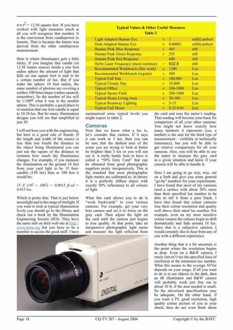
summarized some typical levels you might expect in table 2.
CamerasNow that we know what a lux is, let’s consider that camera. If it says it can work at 3 lux, then you can be sure that the darkest area of the scene you are trying to look at better be brighter than 3 lux or you will not see it. A really handy item to have is called a “50% Grey Card” that can be obtained from good photographic suppliers pretty inexpensively. This is the standard that most photographic light meters are calibrated to. In theory it is a perfectly diffuse object with exactly 50% reflectance to all colours of light.
What this card allows you to do is “work backwards” to your various cameras. For example, get your very best camera and set it to focus on the gray card. Then adjust the light on the card until the camera just begins to lose quality. At that point, take an inexpensive photographic light meter and measure the light reflected from
the card and note the meter’s reading. That reading will become your basis for comparison of all your other cameras. You might not know exactly how many lamberts it represents (yes, a lambert is the unit for the third type of measurement – visibility or technically luminance), but you will be able to get relative comparisons for all your cameras. Also, you will be able to use the meter to measure the grey card in a given situation and know if your camera will be able to handle it.
Here I am going to go way, way, out on a limb and give you some general “go-by” numbers for your experiments. I have found that most of my cameras need a surface with about 20% more than their specified lux number to be able to tell it from a pure black. I have also found that colour cameras lose their colour resolution and quality well above their rated lux number. For example, even on my most sensitive colour camera the colours begin to shift dramatically and fade around 10 lux. Since that is a subjective opinion, I would certainly like to hear from any of you with a different experience.
Another thing that is a bit uncertain is the point where the resolution begins to drop. Even on a B&W camera, I rarely (never?) see the specified lines of resolution at the minimum lux number. What this means to the average ATVer depends on your usage. If all you want to do is to see objects in the dark, then an IR illuminator and B&W camera will probably work just fine out to about 10 ft, if the area needed is small. So the advertised specifications may be adequate. On the other hand, if you want a P5, good resolution, high quality colour picture of you in your shack, then do not even think about
Typical Values & Other Useful MeasuresTable 2
Light Adapted Human Eye ± 1 milliLambertDark Adapted Human Eye ± 0.00001 milliLambertHuman Peak Blue Response ± 445 nMHuman Peak Green Response ± 555 nMHuman Peak Red Response 600 nMHeNe Laser Frequency (most common) = 632.8 nMRecommended Workbench (fine work) ± 1200 LuxRecommended Workbench (regular) ± 500 LuxTypical Full Sun ± 100,000 LuxTypical Cloudy Day ± 10,000 LuxTypical Office ± 100-1000 LuxTypical Sports Field ± 200-1000 LuxTypical Home Living Area ± 30-100 LuxTypical Roadway Lighting ± 5-15 LuxTypical Full Moon ± 0.25-0.01 Lux
Copyright © by the BATC CQ-TV 207 - August 2004 Page 19
light levels near the camera’s rating. You will be quite surprised how much light is needed.
I measured the light in several rooms of my house with just the overhead light (two 60 watt bulbs) and found it to be somewhere between 2 and 5 ft-cd (20-50 lux) on most objects. I was not happy with the quality and resolution of the picture from my camcorder camera (a major name brand) until I brought in extra lights and got the levels up to 10 ft-cd (100 lux) or so, even though it was rated for 3 lux operation.
Basically, you will just need to do some experimentation to find the best match between lighting, camera, and purpose. I am certainly interested in hearing the measurements you make using your cameras and grey cards.
LEDsA word is in order here about LEDs. While they are very efficient light sources and are getting quite bright, they can be difficult to use as light sources for cameras. That is because of the beam width. Remember that I said that illuminance was the number of lumens (or candela) spread over a given area. So to get the foot-candles (lumens/ft2) for a white LED we need to check the beam width specifications. I found several with a 20° beam width and a brightness of 2000 mcd. So let’s look at how well that would illuminate an ATV operator sitting in a chair three feet away and holding our 50% grey card.
First we need to determine how much area a 20° beam covers at 3 feet:
3 ft × 12 in/ft × sin(20°) = 12 inches in diameter
Well, that is a pretty tight spot. Let’s continue anyway. Next we need to calculate the area in that spot:
π·r2 =(0.5 ft)2 X 3.1416 = 0.785 ft2
Now that we have the intensity and the area we can calculate the illuminance:
(2000 mcd × 0.001 cd/mcd × 12.57 lumen/cd ) ÷ 0.785 ft2 = 32 foot-candles = 327 lux
Wow, that is most likely plenty bright for most cameras and for about 1/800th the power that would be required for an incandescent bulb. BUT, it only covers about 0.8 square foot where the incandescent bulb would be covering 144 times more area. That tells us that some form of beam spreader will usually be needed with LEDs unless you can use several and point them to create a wider beam.
SummaryThe best advice I can give you is to experiment with controlled situations. If you get your grey card and calibrate a meter for your camera, then you should be ready to know what to expect when you are out “on the road”. If I get enough good numbers from all of you, I will publish them in a future column and try to discuss what they mean and why they happened the way they did.
As for me, I think I am leaning towards a dual system. Colour for daylight and IR illuminated for low light and night. Now I just need to calculate the path loss on the 2.4 GHz wireless transmitter and see if I can find a way to keep it
and still receive it at the house 700 ft away.
Until next time, keep your pictures bright and your transmissions P5.
References1. William Feather (1889–1981),
“An education isn’t how much you have committed to memory, or even how much you know. It’s being able to differentiate between what you do know and what you don’t. It’s knowing where to go to find out what you need to know; and it’s knowing how to use the information you get.”, Quotable Quotes on Education, p. 17 (1968). Unverified. This is possibly the source of the quote often abbreviated and attributed to Einstein. Just about any quote that people spread around without knowing where it came from gets attributed to Lincoln, Edison, or Einstein. So, if anyone knows the paper or speech that proves the knowledge/education quote came from Einstein, please let me know.
2. “Lighting Handbook”, Illumination Engineering Society of North America (IESNA)
3. Design Guides, Various, (IESNA)
4. “You Light up my…Screen”, Ron Sparks, CQ VHF magazine, April 2000
5. http://www.reflect-a-light.com/LuminanceRec.htm
This article is re-printed from ATVQ, Spring 2004. http://www.hampubs.com
Page 20 CQ-TV 207 - August 2004 Copyright © by the BATC
By Trevor Brown
We had a request at the BGM to cover the subject of tape editing. I have edited
programmes for ITV, BBC, Sky and Channel 4 and built several edit suites of my own. Let me start with a brief history and an introduction to some of the redundant equipment that is around and what it can do.
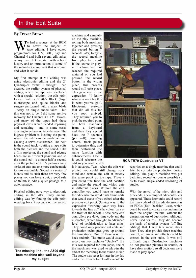
My first attempt at VT editing was using electronic editing and the 2” Quadruplex format. I thought I had escaped the earlier system of physical editing, where the tape was developed with a special solution, the edit point located with a Smith’s Block (large microscope and splice block) and surgery performed with a razor blade - scary on single ended takes - but this was not to be. I did some archive recovery for Channel 4’s TV Heaven, and many of the tapes had these physical edits which needed repairing and remaking - and in some cases creating to get around tape damage. The biggest problem is locating the points where the edit can be made without causing a servo disturbance. The next is the sound track - cutting a tape edits both the pictures and the sound. Like a film projector, the sound and picture heads are in different positions and so the sound edit is almost half a second after the picture edit. TV pictures are a series of cuts and one more can be made to look reasonable. Sound is a series of blends and as such there are very few places you can have a cut; a good rule of thumb is edit a quiet passage to a quiet passage.
Physical editing gave way to electronic editing in the 70’s. Early manual editing was by finding the edit point winding back 7 seconds on the record
machine and similarly on the play machine, rolling both machines together and pressing the record button 7 seconds later, to cycle the record machine from play to record. If the source or play-in machine had not reached the required material or you had pressed the record button in the wrong place, this process would still take place. This gave rise to the expression “I know what you want but this is what you’ve got”. Electronic systems that did all this for you soon arrived. They required you to pick the required point on both machines from a keyboard and then they cycled back the 7 seconds (pre roll), counting control track pulses to determine this, and then performed the same function with enhancements. One - it could rehearse the edit so you could check it in advance. Two - when the edit was printed you could still change your mind and remake the edit at exactly the same point on the tape. Three - you could fine tune the edit position and make the sound and vision cuts in different places. Without the edit controller you would have to remake the edit earlier to avoid flash frame edits that would occur if you edited after the previous edit point. (Giving way to the expression “working your way back towards the line up”, (the colour bars at the front of the tape)). These early edit controllers pre-dated time code and the microchip, which brought an advanced level of sophistication to later units. They could only produce cut edits and production techniques grew up around the limitations. One of these was roll back and mix. The studio would usually record on two machines “Duplex”. If a mix was required for time lapse, one of the machines was used to play-in the end of the recording to the vision mixer. The studio was reset for later in the day and a mix from before to after would be
recorded on a single machine that could later be cut into the production during editing. The play-in machine was put back into record as soon as possible so as to avoid single ended recording of studio.
With the arrival of the micro chip and time code, a new range of edit controllers appeared. These later units could record the time code of all the edit decisions as an EDL’s (Edit Decision Lists), which could be used to create a second master from the original material without the generation loss of duplication. Although never used for this, they did become the basis of another system (off line editing) that I will talk more about later. They also provide three-machine control, so mixes and effects could be created in the edit suite. It was still difficult days. Quadruplex machines do not produce pictures in shuttle, or have slow motion, so all decisions were made at play speed
In the Edit Suite
RCA TR70 Quadruplex VT
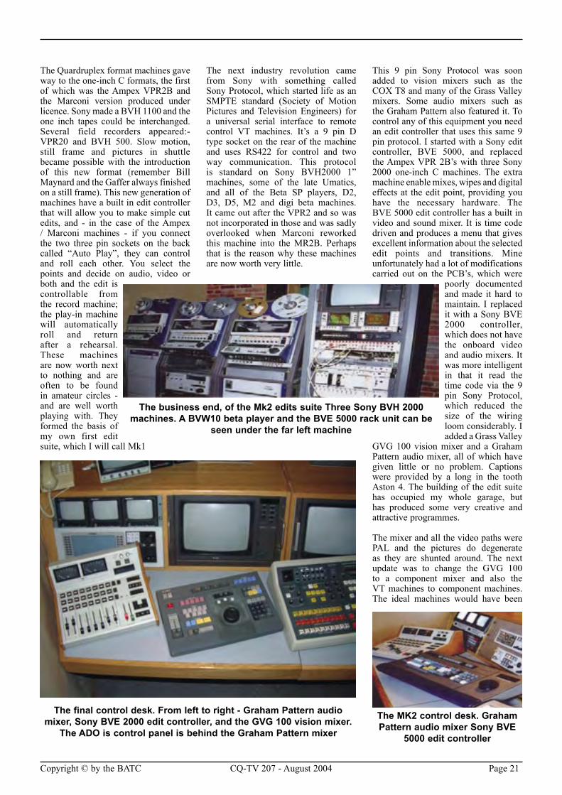
The missing link - the A500 digi beta machine alas well beyond
my budget
Copyright © by the BATC CQ-TV 207 - August 2004 Page 21
The Quardruplex format machines gave way to the one-inch C formats, the first of which was the Ampex VPR2B and the Marconi version produced under licence. Sony made a BVH 1100 and the one inch tapes could be interchanged. Several field recorders appeared:- VPR20 and BVH 500. Slow motion, still frame and pictures in shuttle became possible with the introduction of this new format (remember Bill Maynard and the Gaffer always finished on a still frame). This new generation of machines have a built in edit controller that will allow you to make simple cut edits, and - in the case of the Ampex / Marconi machines - if you connect the two three pin sockets on the back called “Auto Play”, they can control and roll each other. You select the points and decide on audio, video or both and the edit is controllable from the record machine; the play-in machine will automatically roll and return after a rehearsal. These machines are now worth next to nothing and are often to be found in amateur circles - and are well worth playing with. They formed the basis of my own first edit suite, which I will call Mk1
The next industry revolution came from Sony with something called Sony Protocol, which started life as an SMPTE standard (Society of Motion Pictures and Television Engineers) for a universal serial interface to remote control VT machines. It’s a 9 pin D type socket on the rear of the machine and uses RS422 for control and two way communication. This protocol is standard on Sony BVH2000 1” machines, some of the late Umatics, and all of the Beta SP players, D2, D3, D5, M2 and digi beta machines. It came out after the VPR2 and so was not incorporated in those and was sadly overlooked when Marconi reworked this machine into the MR2B. Perhaps that is the reason why these machines are now worth very little.
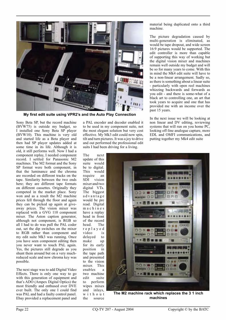
This 9 pin Sony Protocol was soon added to vision mixers such as the COX T8 and many of the Grass Valley mixers. Some audio mixers such as the Graham Pattern also featured it. To control any of this equipment you need an edit controller that uses this same 9 pin protocol. I started with a Sony edit controller, BVE 5000, and replaced the Ampex VPR 2B’s with three Sony 2000 one-inch C machines. The extra machine enable mixes, wipes and digital effects at the edit point, providing you have the necessary hardware. The BVE 5000 edit controller has a built in video and sound mixer. It is time code driven and produces a menu that gives excellent information about the selected edit points and transitions. Mine unfortunately had a lot of modifications carried out on the PCB’s, which were
poorly documented and made it hard to maintain. I replaced it with a Sony BVE 2000 controller, which does not have the onboard video and audio mixers. It was more intelligent in that it read the time code via the 9 pin Sony Protocol, which reduced the size of the wiring loom considerably. I added a Grass Valley
GVG 100 vision mixer and a Graham Pattern audio mixer, all of which have given little or no problem. Captions were provided by a long in the tooth Aston 4. The building of the edit suite has occupied my whole garage, but has produced some very creative and attractive programmes.
The mixer and all the video paths were PAL and the pictures do degenerate as they are shunted around. The next update was to change the GVG 100 to a component mixer and also the VT machines to component machines. The ideal machines would have been
The MK2 control desk. Graham Pattern audio mixer Sony BVE
5000 edit controller
The business end, of the Mk2 edits suite Three Sony BVH 2000 machines. A BVW10 beta player and the BVE 5000 rack unit can be
seen under the far left machine
The final control desk. From left to right - Graham Pattern audio mixer, Sony BVE 2000 edit controller, and the GVG 100 vision mixer.
The ADO is control panel is behind the Graham Pattern mixer
Page 22 CQ-TV 207 - August 2004 Copyright © by the BATC
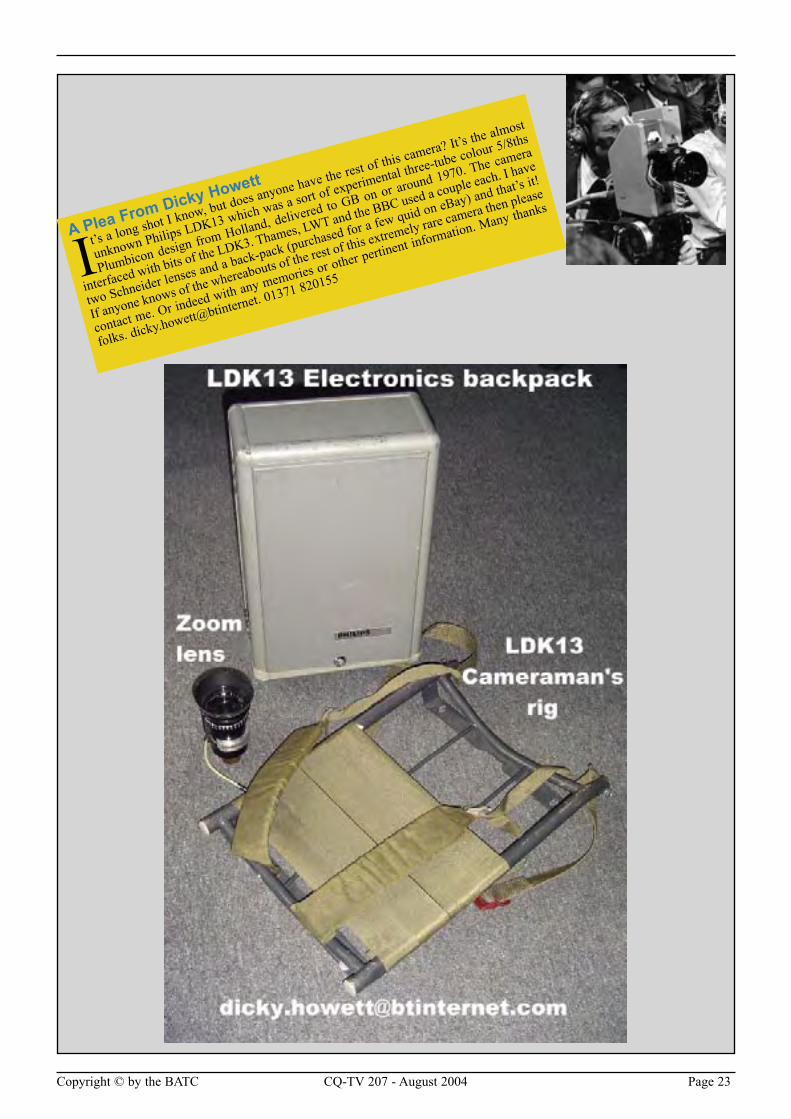
Sony Beta SP, but the record machine (BVW75) is outside my budget, so I installed one Sony Beta SP player (BVW10). This machine is very old and started life as a Beta player and then had SP player updates added at some time in its life. Although it is old, it still performs well. Now I had a component replay, I needed component record. I settled for Panasonic M2 machines. The M2 format and the Sony SP format were both component, in that the luminance and the chroma are recorded on different tracks on the tape. Similarity between the two ends here; they are different tape formats on different cassettes. Originally they competed in the market place. Sony won and as a result the M2 machine prices fell through the floor and again they can be picked up again at give-away prices. The vision mixer was replaced with a GVG 110 component mixer. The Aston caption generator, although not component, is RGB so all I had to do was pull the PAL coder out, set the dip switches on the mixer to RGB rather than component and my edit suite Mk3 was running. Once you have seen component editing then you never want to touch PAL again. Yes, the pictures still degrade as you shunt them around but on a very much-reduced scale and now chroma key was possible.
The next stage was to add Digital Video Effects. There is only one way to go with this generation of equipment and that’s ADO (Ampex Digital Optics) the most friendly and enthused over DVE ever built. The only one I could find was PAL and had a faulty control panel. Ebay provided a replacement panel and
a PAL encoder and decoder enabled it to be used in my component suite, not the most elegant solution but very cost effective. My Mk3 edit could now spin, tilt and turn pictures. It was a joy to drive and out performed the professional edit suits I had been driving for a living.
The next update of this suite would be to digital. This would require an SDI vision mixer and two digital VTs. The biggest a d v a n t a g e would be pre read. Digital m a c h i n e s have a replay head in front of the record head. The r e p l a y e d video is delayed to make up for its early position in the tape path and presented to the vision mixer. This enables a two machine edit suite to perform wipes mixes and inlays, w i t h o u t the source
material being duplicated onto a third machine.
The picture degradation caused by multi-generation is eliminated, as would be tape dropout, and wide screen 16:9 pictures would be supported. The edit controller is more than capable of supporting this way of working but the digital vision mixer and machines remain well outside my budget and will be so for many years to come. With this in mind the Mk4 edit suite will have to be a non-linear arrangement. Sadly so, as there is something about a linear suite - particularly with open reel machines whizzing backwards and forwards as you edit - and there is some-what of a black art to controlling one, an art that took years to acquire and one that has provided me with an income over the past 15 years.
In the next issue we will be looking at non linear and DV editing, reviewing systems that will run on you home PC, looking off-line analogue capture, more EDL and OMFI communications, and putting together my Mk4 edit suite
My first edit suite using VPR2’s and the Auto Play Connection
The M2 machine rack which replaces the 3 1 inch machines
Copyright © by the BATC CQ-TV 207 - August 2004 Page 23
A Plea From Dicky Howett
It’s a long shot I know, but does anyone have the rest of this camera? It’s the almost
unknown Philips LDK13 which was a sort of experimental three-tube colour 5/8ths
Plumbicon design from Holland, delivered to GB on or around 1970. The camera
interfaced with bits of the LDK3. Thames, LWT and the BBC used a couple each. I have
two Schneider lenses and a back-pack (purchased for a few quid on eBay) and that’s it!
If anyone knows of the whereabouts of the rest of this extremely rare camera then please
contact me. Or indeed with any memories or other pertinent information. Many thanks
folks. dicky.howett@btinternet. 01371 820155
Page 26 CQ-TV 207 - August 2004 Copyright © by the BATC
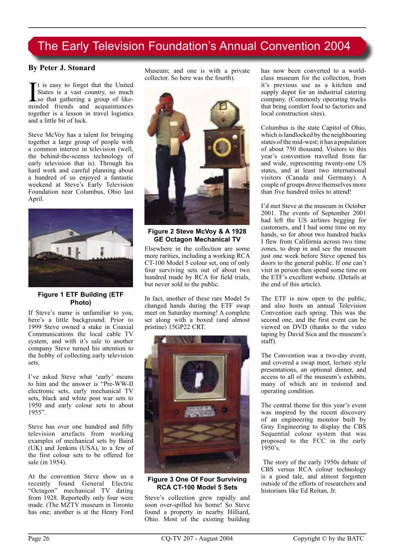
By Peter J. Stonard
It is easy to forget that the United States is a vast country, so much so that gathering a group of like-
minded friends and acquaintances together is a lesson in travel logistics and a little bit of luck.
Steve McVoy has a talent for bringing together a large group of people with a common interest in television (well, the behind-the-scenes technology of early television that is). Through his hard work and careful planning about a hundred of us enjoyed a fantastic weekend at Steve’s Early Television Foundation near Columbus, Ohio last April.
Figure 1 ETF Building (ETF Photo)
If Steve’s name is unfamiliar to you, here’s a little background. Prior to 1999 Steve owned a stake in Coaxial Communications the local cable TV system, and with it’s sale to another company Steve turned his attention to the hobby of collecting early television sets.
I’ve asked Steve what ‘early’ means to him and the answer is “Pre-WW-II electronic sets, early mechanical TV sets, black and white post war sets to 1950 and early colour sets to about 1955”.
Steve has over one hundred and fifty television artefacts from working examples of mechanical sets by Baird (UK) and Jenkins (USA), to a few of the first colour sets to be offered for sale (in 1954).
At the convention Steve show us a recently found General Electric “Octagon” mechanical TV dating from 1928. Reportedly only four were made. (The MZTV museum in Toronto has one; another is at the Henry Ford
Museum; and one is with a private collector. So here was the fourth).
Figure 2 Steve McVoy & A 1928 GE Octagon Mechanical TV
Elsewhere in the collection are some more rarities, including a working RCA CT-100 Model 5 colour set, one of only four surviving sets out of about two hundred made by RCA for field trials, but never sold to the public.
In fact, another of these rare Model 5s changed hands during the ETF swap meet on Saturday morning! A complete set along with a boxed (and almost pristine) 15GP22 CRT.
Figure 3 One Of Four Surviving RCA CT-100 Model 5 Sets
Steve’s collection grew rapidly and soon over-spilled his home! So Steve found a property in nearby Hilliard, Ohio. Most of the existing building
has now been converted to a world-class museum for the collection, from it’s previous use as a kitchen and supply depot for an industrial catering company. (Commonly operating trucks that bring comfort food to factories and local construction sites).
Columbus is the state Capitol of Ohio, which is landlocked by the neighbouring states of the mid-west; it has a population of about 750 thousand. Visitors to this year’s convention travelled from far and wide, representing twenty-one US states, and at least two international visitors (Canada and Germany). A couple of groups drove themselves more than five hundred miles to attend!
I’d met Steve at the museum in October 2001. The events of September 2001 had left the US airlines begging for customers, and I had some time on my hands, so for about two hundred bucks I flew from California across two time zones, to drop in and see the museum just one week before Steve opened his doors to the general public. If one can’t visit in person then spend some time on the ETF’s excellent website. (Details at the end of this article).
The ETF is now open to the public, and also hosts an annual Television Convention each spring. This was the second one, and the first event can be viewed on DVD (thanks to the video taping by David Sica and the museum’s staff).
The Convention was a two-day event, and covered a swap meet, lecture style presentations, an optional dinner, and access to all of the museum’s exhibits, many of which are in restored and operating condition.
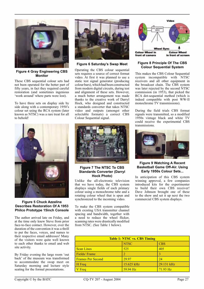
The central theme for this year’s event was inspired by the recent discovery of an engineering monitor built by Gray Engineering to display the CBS Sequential colour system that was proposed to the FCC in the early 1950’s.
The story of the early 1950s debate of CBS versus RCA colour technology is a good tale, and almost forgotten outside of the efforts of researchers and historians like Ed Reitan, Jr.
The Early Television Foundation’s Annual Convention 2004
Copyright © by the BATC CQ-TV 207 - August 2004 Page 27
Figure 4 Gray Engineering CBS Monitor
These CBS sequential colour sets had not been operated for the better part of fifty years, in fact they required careful restoration (and sometimes ingenious ‘work around’ where parts were lost).
To have three sets on display side by side along with a contemporary 1950’s colour set using the RCA system (later known as NTSC) was a rare treat for all to behold!
Figure 5 Chuck Azzalina Describes Restoration Of A 1953 Philco Prototype 15inch Console
The author arrived late on Friday, and at the time only knew Steve from prior face-to-face contact. However, over the duration of the convention it was a thrill to put the faces, voices, and names to their respective email addresses! Many of the visitors were quite well known to each other thanks to email and web site activity.
By Friday evening the large room ‘out back’ of the museum was transformed to accommodate the swap meet on Saturday morning and lecture style seating for the formal presentations.
Figure 6 Saturday’s Swap MeetOperating the CBS colour sequential sets requires a source of correct format video. At first it was planned to use a static test signal generator (producing colour bars), which had been constructed from modern digital circuits, during test and alignment of these sets. However, a much better arrangement was made thanks to the creative work of Darryl Hock, who designed and constructed a standards converter that takes NTSC video and outputs (amongst other selectable formats) a correct CBS Colour Sequential signal.
Figure 7 The NTSC To CBS Standards Converter (Darryl
Hock Photo)Unlike the all-electronic television that we have today, the CBS system displays single fields of each primary colour using a monochrome tube and a rotating colour wheel that is spun and synchronized to the incoming video.
To make the CBS system compatible with existing USA transmitter channel spacing and bandwidth, together with a need to reduce the wheel flicker, scanning rates were drastically modified from NTSC. (See Table 1 below).
Figure 8 Principle Of The CBS Colour Sequential System
This makes the CBS Colour Sequential system incompatible with NTSC receivers and all other equipment in the broadcast chain. The CBS system was later rejected by the second NTSC commission (in 1953), that picked the RCA dot-sequential method (which is indeed compatible with post WW-II monochrome TV transmissions).
During the field trials CBS format signals were transmitted, so a modified 1950s vintage black and white TV could receive the experimental CBS transmissions.
Figure 9 Watching A Recent Basketball Game Off-Air. Using
Early 1950s Colour Sets...In anticipation of this CBS system winning approval, a few companies introduced kits for the experimenter to build their own CBS receiver! Dave Johnson brought one of these to the show and set it up next the two commercial CBS system displays.
Table 1: NTSC vs. CBS TimingNTSC CBS
Scan Lines 525 405Fields/ Frame 2 3Frames Per Second 29.97 24H Freq 15.625 kHz 29.131 kHzV Freq 59.94 Hz 71.93 Hz
Page 28 CQ-TV 207 - August 2004 Copyright © by the BATC
The colourful film “The Wizard Of Oz” starring Judy Garland (1939) played from DVD to setting the right atmosphere.
After the swap meet (aka indoor ‘boot sale’) a buffet lunch was served before launching into the formal lecture sessions. A projection TV system was set up and put to good use during the lunch by screening “TV Comes to London” (1936) and a pre-WW-II Germany TV documentary.
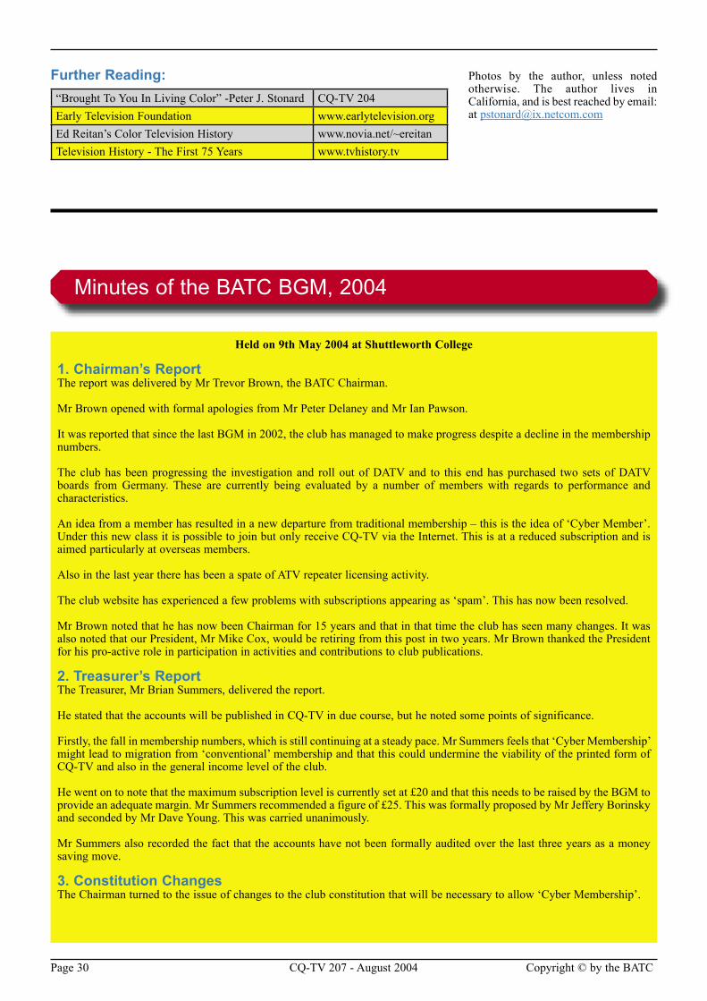
The presentations were introduced by the master of ceremony, Tom Genova, author of the excellent website and curator of the fine paper artefact collection at “TV History dot TV”.
Figure 12 Tom Genova: Master Of Ceremony, TV History dot TV Web Master, And Archivist
Extraordinaire
The author was not the only person in the room to be stunned by the clarity and rich colours of the CBS system! Had the author been on the 1951 National Television Selection Committee the CBS system clearly triumphed over the early RCA efforts.
However, for the future, NTSC was the right decision and it has existed almost intact for half a century.
Only one small problem; these sets have moving parts, and sound a bit like a washing machine on ‘spin’ cycle.
The other presentations (table 2) were a combination of slideshows and actual hardware artefacts. They covered a wide range!
Dave Johnson demonstrated an all-mechanical TV system featuring the Western Television Visionette mechanical TV receiver driven from a mechanical TV camera, and rotating marionette, hidden behind Dave’s display table.
Figure 13 Chuck Pharis Reveals The Original RCA ‘Indian Head’
Test Card ArtworkThe story behind the discovery of original artwork (in a dumpster behind the RCA premises during demolition)
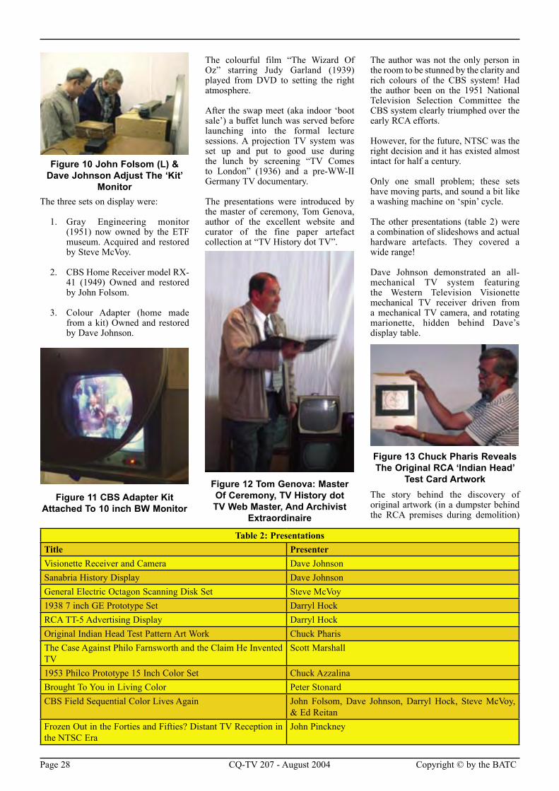
Figure 10 John Folsom (L) & Dave Johnson Adjust The ‘Kit’
MonitorThe three sets on display were:
1. Gray Engineering monitor (1951) now owned by the ETF museum. Acquired and restored by Steve McVoy.
2. CBS Home Receiver model RX-41 (1949) Owned and restored by John Folsom.
3. Colour Adapter (home made from a kit) Owned and restored by Dave Johnson.
Figure 11 CBS Adapter Kit Attached To 10 inch BW Monitor
Table 2: PresentationsTitle PresenterVisionette Receiver and Camera Dave JohnsonSanabria History Display Dave JohnsonGeneral Electric Octagon Scanning Disk Set Steve McVoy1938 7 inch GE Prototype Set Darryl HockRCA TT-5 Advertising Display Darryl HockOriginal Indian Head Test Pattern Art Work Chuck PharisThe Case Against Philo Farnsworth and the Claim He Invented TV
Scott Marshall
1953 Philco Prototype 15 Inch Color Set Chuck AzzalinaBrought To You in Living Color Peter StonardCBS Field Sequential Color Lives Again John Folsom, Dave Johnson, Darryl Hock, Steve McVoy,
& Ed ReitanFrozen Out in the Forties and Fifties? Distant TV Reception in the NTSC Era
John Pinckney
Copyright © by the BATC CQ-TV 207 - August 2004 Page 29
of television, transmitted live from the 1939 World’s Fair.
Figure 16 Visitors Watch “The Wizard Of Oz” On a 30inch
DuMontOn Sunday morning we picked up where we left off, having made a last minute shuffle to the lecture series (due to modern technology letting us down – John Pinckney’s presentation of DX TV required a DVD playback of screen shots and transcribed video recordings that would not play during Saturday’s session).
The museum has a second early RCA camera, based on the smaller four and a half inch Iconoscope tube. I was walking past the exhibit and over heard a comment from a couple of visitors to the museum (and not part of the convention crowd)
Figure 17 Dave Johnson’s CRT Collection
“Funny that they waited so long after the (American) civil war to give us television” said the lady. Her husband agreed that it was. I couldn’t let such an error hang in the air, so I asked why they were discussing the civil war.
“Well” said the lady “The sign says this camera used the 1848 Iconoscope, and I know that the civil war ended in 1865”
“Oh, that’s the RCA tube number, let me show you some more camera tubes, all invented just before WW-II, over here” I replied.
Figure 18 RCA Experimental Camera Used At The 1939
World’s Fair
Figure 19 RCA Experimental Camera With ‘1848’ Iconoscope
Tube
Sometimes we forget that enthusiasts talk amongst themselves in technical shorthand.
Chuckles all around, the couple toured all the exhibits and said they enjoyed the visit. We’re all looking forward to next year! See you in Hilliard, Ohio.
for the famed RCA ‘Indian Head’ television test pattern was presented by broadcast hardware collector Chuck Pharis.
Following the first lecture session we gathered around the CBS sets for a live demonstration. Also on stage was a prototype Philco 15inch colour set, owned, restored and presented by Chuck Azzalina.
Figure 14 CBS Sequential Colour Demo Draws A Crowd
The formal ‘family style’ dinner, attended by over half the convention visitors, was held at the nearby Yard Arm restaurant in historic downtown Hilliard, Ohio.
Figure 15 Darryl Hock Presents A Pristine RCA TT5 Dealer Sales
Kit
The climax for the event was the operation of many of the museum’s collection. Typically, Steve allows unfettered access to the sets (should one need to look inside or take measurements). Upon request the staff will run any set, but they are usually turned off to preserve their delicate electronic valves and rare picture tubes.
The museum is now the home to Dave Johnson’s Cathode Ray Tube collection, covering many of the tubes adapted from radar and oscilloscopes for use in pre-WW-II TV, to the monster DuMont monochrome 30inch with a huge metal envelope.
Geoff Bourne hand carried his RCA Iconoscope TV camera for display over the weekend. This experimental camera was used at the first public broadcast
Page 30 CQ-TV 207 - August 2004 Copyright © by the BATC
Further Reading: Photos by the author, unless noted otherwise. The author lives in California, and is best reached by email: at [email protected]
“Brought To You In Living Color” -Peter J. Stonard CQ-TV 204Early Television Foundation www.earlytelevision.orgEd Reitan’s Color Television History www.novia.net/~ereitanTelevision History - The First 75 Years www.tvhistory.tv
Held on 9th May 2004 at Shuttleworth College
1. Chairman’s ReportThe report was delivered by Mr Trevor Brown, the BATC Chairman.
Mr Brown opened with formal apologies from Mr Peter Delaney and Mr Ian Pawson.
It was reported that since the last BGM in 2002, the club has managed to make progress despite a decline in the membership numbers.
The club has been progressing the investigation and roll out of DATV and to this end has purchased two sets of DATV boards from Germany. These are currently being evaluated by a number of members with regards to performance and characteristics.
An idea from a member has resulted in a new departure from traditional membership – this is the idea of ‘Cyber Member’. Under this new class it is possible to join but only receive CQ-TV via the Internet. This is at a reduced subscription and is aimed particularly at overseas members.
Also in the last year there has been a spate of ATV repeater licensing activity.
The club website has experienced a few problems with subscriptions appearing as ‘spam’. This has now been resolved.
Mr Brown noted that he has now been Chairman for 15 years and that in that time the club has seen many changes. It was also noted that our President, Mr Mike Cox, would be retiring from this post in two years. Mr Brown thanked the President for his pro-active role in participation in activities and contributions to club publications.
2. Treasurer’s ReportThe Treasurer, Mr Brian Summers, delivered the report.
He stated that the accounts will be published in CQ-TV in due course, but he noted some points of significance.
Firstly, the fall in membership numbers, which is still continuing at a steady pace. Mr Summers feels that ‘Cyber Membership’ might lead to migration from ‘conventional’ membership and that this could undermine the viability of the printed form of CQ-TV and also in the general income level of the club.
He went on to note that the maximum subscription level is currently set at £20 and that this needs to be raised by the BGM to provide an adequate margin. Mr Summers recommended a figure of £25. This was formally proposed by Mr Jeffery Borinsky and seconded by Mr Dave Young. This was carried unanimously.
Mr Summers also recorded the fact that the accounts have not been formally audited over the last three years as a money saving move.
3. Constitution ChangesThe Chairman turned to the issue of changes to the club constitution that will be necessary to allow ‘Cyber Membership’.
Minutes of the BATC BGM, 2004
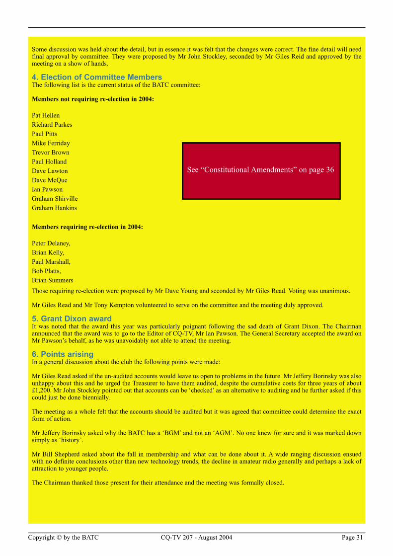
Copyright © by the BATC CQ-TV 207 - August 2004 Page 31
Some discussion was held about the detail, but in essence it was felt that the changes were correct. The fine detail will need final approval by committee. They were proposed by Mr John Stockley, seconded by Mr Giles Reid and approved by the meeting on a show of hands.
4. Election of Committee MembersThe following list is the current status of the BATC committee:
Members not requiring re-election in 2004:
Pat HellenRichard ParkesPaul PittsMike FerridayTrevor BrownPaul HollandDave LawtonDave McQueIan PawsonGraham ShirvilleGraham Hankins
Members requiring re-election in 2004:
Peter Delaney,Brian Kelly,Paul Marshall,Bob Platts,Brian SummersThose requiring re-election were proposed by Mr Dave Young and seconded by Mr Giles Read. Voting was unanimous.
Mr Giles Read and Mr Tony Kempton volunteered to serve on the committee and the meeting duly approved.
5. Grant Dixon awardIt was noted that the award this year was particularly poignant following the sad death of Grant Dixon. The Chairman announced that the award was to go to the Editor of CQ-TV, Mr Ian Pawson. The General Secretary accepted the award on Mr Pawson’s behalf, as he was unavoidably not able to attend the meeting.
6. Points arisingIn a general discussion about the club the following points were made:
Mr Giles Read asked if the un-audited accounts would leave us open to problems in the future. Mr Jeffery Borinsky was also unhappy about this and he urged the Treasurer to have them audited, despite the cumulative costs for three years of about £1,200. Mr John Stockley pointed out that accounts can be ‘checked’ as an alternative to auditing and he further asked if this could just be done biennially.
The meeting as a whole felt that the accounts should be audited but it was agreed that committee could determine the exact form of action.
Mr Jeffery Borinsky asked why the BATC has a ‘BGM’ and not an ‘AGM’. No one knew for sure and it was marked down simply as ‘history’.
Mr Bill Shepherd asked about the fall in membership and what can be done about it. A wide ranging discussion ensued with no definite conclusions other than new technology trends, the decline in amateur radio generally and perhaps a lack of attraction to younger people.
The Chairman thanked those present for their attendance and the meeting was formally closed.
See “Constitutional Amendments” on page 36
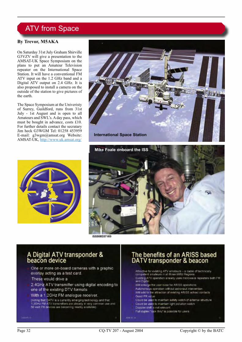
Page 32 CQ-TV 207 - August 2004 Copyright © by the BATC
By Trevor, M5AKA
On Saturday 31st July Graham Shirville G3VZV will give a presentation to the AMSAT-UK Space Symposium on the plans to put an Amateur Television repeater on the International Space Station. It will have a conventional FM ATV input on the 1.2 GHz band and a Digital ATV output on 2.4 GHz. It is also proposed to install a camera on the outside of the station to give pictures of the earth.
The Space Symposium at the Univeristy of Surrey, Guildford, runs from 31st July - 1st August and is open to all Amateurs and SWL’s. A day pass, which must be bought in advance, costs £10. For further details contact the secratary Jim heck G3WGM Tel: 01258 453959 E-mail: [email protected] Website: AMSAT-UK, http://www.uk.amsat.org/
ATV from Space
International Space Station
Mike Foale onboard the ISS
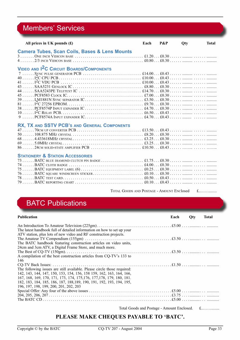
Copyright © by the BATC CQ-TV 207 - August 2004 Page 33
BATC Publications
Publication Each Qty Total
An Introduction To Amateur Television (225gm) . . . . . . . . . . . . . . . . . . . . . . . . . . . . . . . . . . . . . £5.00 . . . . .......... . . . ...........The latest handbook full of detailed information on how to set up your ATV station, plus lots of new video and RF construction projects.The Amateur TV Compendium (155gm) . . . . . . . . . . . . . . . . . . . . . . . . . . . . . . . . . . . . . . . . . . . £3.50 . . . . .......... . . . ............The BATC handbook featuring construction articles on video units, 24cm and 3cm ATV, a Digital Frame Store, and much more.The Best of CQ-TV (150gm). . . . . . . . . . . . . . . . . . . . . . . . . . . . . . . . . . . . . . . . . . . . . . . . . . . . . £3.50 . . . . .......... . . . ............A compilation of the best construction articles from CQ-TV’s 133 to 146CQ-TV Back Issues: . . . . . . . . . . . . . . . . . . . . . . . . . . . . . . . . . . . . . . . . . . . . . . . . . . . . . . . . . . . £1.50 . . . . .......... . . . ............The following issues are still available. Please circle those required: 142, 143, 144, 147, 150, 153, 154, 156, 158 159, 162, 163, 164, 166, 167, 168, 169, 170, 171, 173, 174, 175,176, 177,178, 179, 180, 181. 182, 183, 184, 185, 186, 187, 188,189, 190, 191, 192, 193, 194, 195, 196, 197, 198, 199, 200, 201, 202, 203Special Offer: Any four of the above issues . . . . . . . . . . . . . . . . . . . . . . . . . . . . . . . . . . . . . . . . . £5.00 . . . . .......... . . . ............204, 205, 206, 207 . . . . . . . . . . . . . . . . . . . . . . . . . . . . . . . . . . . . . . . . . . . . . . . . . . . . . . . . . . . . . £3.75 . . . . .......... . . . ............The BATC CD . . . . . . . . . . . . . . . . . . . . . . . . . . . . . . . . . . . . . . . . . . . . . . . . . . . . . . . . . . . . . . . . £5.00 . . . . .......... . . . ............
Total Goods and Postage - Amount Enclosed. £..……........
All prices in UK pounds (£) Each P&P Qty Total
Camera Tubes, Scan Coils, Bases & Lens Mounts3 . . . . . . . ONE INCH VIDICON BASE . . . . . . . . . . . . . . . . . . . . . . . . . . . . . . . . . . £1.20. . . £0.30 . . . . . . .......... . . . . . . ..........4 . . . . . . . 2/3 INCH VIDICON BASE . . . . . . . . . . . . . . . . . . . . . . . . . . . . . . . . . . . £0.80. . . £0.30 . . . . . . .......... . . . . . . ..........
VIDEO AND I2C CIRCUIT BOARDS/COMPONENTS 7 . . . . . . SYNC PULSE GENERATOR PCB . . . . . . . . . . . . . . . . . . . . . . . . . . . . . £14.00. . . £0.43 . . . . . . .......... . . . . . . ..........40 . . . . . . I2C CPU PCB . . . . . . . . . . . . . . . . . . . . . . . . . . . . . . . . . . . . . . . . . £10.00. . . £0.43 . . . . . . .......... . . . . . . ..........41 . . . . . . I2C VDU PCB . . . . . . . . . . . . . . . . . . . . . . . . . . . . . . . . . . . . . . . . £10.00. . . £0.43 . . . . . . .......... . . . . . . ..........43 . . . . . . SAA5231 GENLOCK IC . . . . . . . . . . . . . . . . . . . . . . . . . . . . . . . . . . . £8.80. . . £0.30 . . . . . . .......... . . . . . . ..........44 . . . . . . SAA5243PE TELETEXT IC . . . . . . . . . . . . . . . . . . . . . . . . . . . . . . . £14.70. . . £0.30 . . . . . . .......... . . . . . . ..........45 . . . . . . PCF8583 CLOCK IC. . . . . . . . . . . . . . . . . . . . . . . . . . . . . . . . . . . . . . £7.00. . . £0.30 . . . . . . .......... . . . . . . ..........39 . . . . . . LM1881N SYNC SEPARATOR IC . . . . . . . . . . . . . . . . . . . . . . . . . . . . . £3.50. . . £0.30 . . . . . . .......... . . . . . . ..........81 . . . . . . I2C 27256 EPROM. . . . . . . . . . . . . . . . . . . . . . . . . . . . . . . . . . . . . . £9.70. . . £0.30 . . . . . . .......... . . . . . . ..........38 . . . . . . PCF8574P INPUT EXPANDER IC . . . . . . . . . . . . . . . . . . . . . . . . . . . . . £4.70. . . £0.30 . . . . . . .......... . . . . . . ..........10 . . . . . . I2C RELAY PCB. . . . . . . . . . . . . . . . . . . . . . . . . . . . . . . . . . . . . . . . . £6.50. . . £0.43 . . . . . . .......... . . . . . . .......... 9 . . . . . . PCF8574A INPUT EXPANDER IC. . . . . . . . . . . . . . . . . . . . . . . . . . . . . £4.70. . . £0.43 . . . . . . ......... . . . . . . ..........
RX, TX AND SSTV PCB’S AND GENERAL COMPONENTS47 . . . . . . 70CM UP CONVERTER PCB . . . . . . . . . . . . . . . . . . . . . . . . . . . . . . . . £13.50. . . £0.43 . . . . . . .......... . . . . . . ..........50 . . . . . . 108.875 MHZ CRYSTAL . . . . . . . . . . . . . . . . . . . . . . . . . . . . . . . . . . . £8.20. . . £0.30 . . . . . . .......... . . . . . . ..........68 . . . . . . 4.433618MHZ CRYSTAL . . . . . . . . . . . . . . . . . . . . . . . . . . . . . . . . . . . £3.25. . . £0.30 . . . . . . .......... . . . . . . ..........69 . . . . . . 5.0MHZ CRYSTAL . . . . . . . . . . . . . . . . . . . . . . . . . . . . . . . . . . . . . . . . £3.25. . . £0.30 . . . . . . .......... . . . . . . ..........86 . . . . . . 24CM SOLID-STATE AMPLIFIER PCB . . . . . . . . . . . . . . . . . . . . . . . . . £10.50. . . £0.43 . . . . . . …….. . . . . . . ……..
STATIONERY & STATION ACCESSORIES73 . . . . . . BATC BLUE DIAMOND CLUTCH PIN BADGE . . . . . . . . . . . . . . . . . . . . . £1.75. . . £0.30 . . . . . . .......... . . . . . . ..........74 . . . . . . BATC CLOTH BADGE . . . . . . . . . . . . . . . . . . . . . . . . . . . . . . . . . . . . . £4.00. . . £0.30 . . . . . . .......... . . . . . . ..........75 . . . . . . BATC EQUIPMENT LABEL (6) . . . . . . . . . . . . . . . . . . . . . . . . . . . . . . . £0.25. . . £0.30 . . . . . . .......... . . . . . . ..........76 . . . . . . BATC SQUARE WINDSCREEN STICKER . . . . . . . . . . . . . . . . . . . . . . . . . £0.10. . . £0.30 . . . . . . .......... . . . . . . ..........78 . . . . . . BATC TEST CARD. . . . . . . . . . . . . . . . . . . . . . . . . . . . . . . . . . . . . . . . £0.50. . . £0.43 . . . . . . .......... . . . . . . ..........79 . . . . . . BATC REPORTING CHART . . . . . . . . . . . . . . . . . . . . . . . . . . . . . . . . . . £0.10. . . £0.43 . . . . . . .......... . . . . . . ..........
TOTAL GOODS AND POSTAGE - AMOUNT ENClosed £..……........
Members’ Services
PLEASE MAKE CHEQUES PAYABLE TO ‘BATC’.
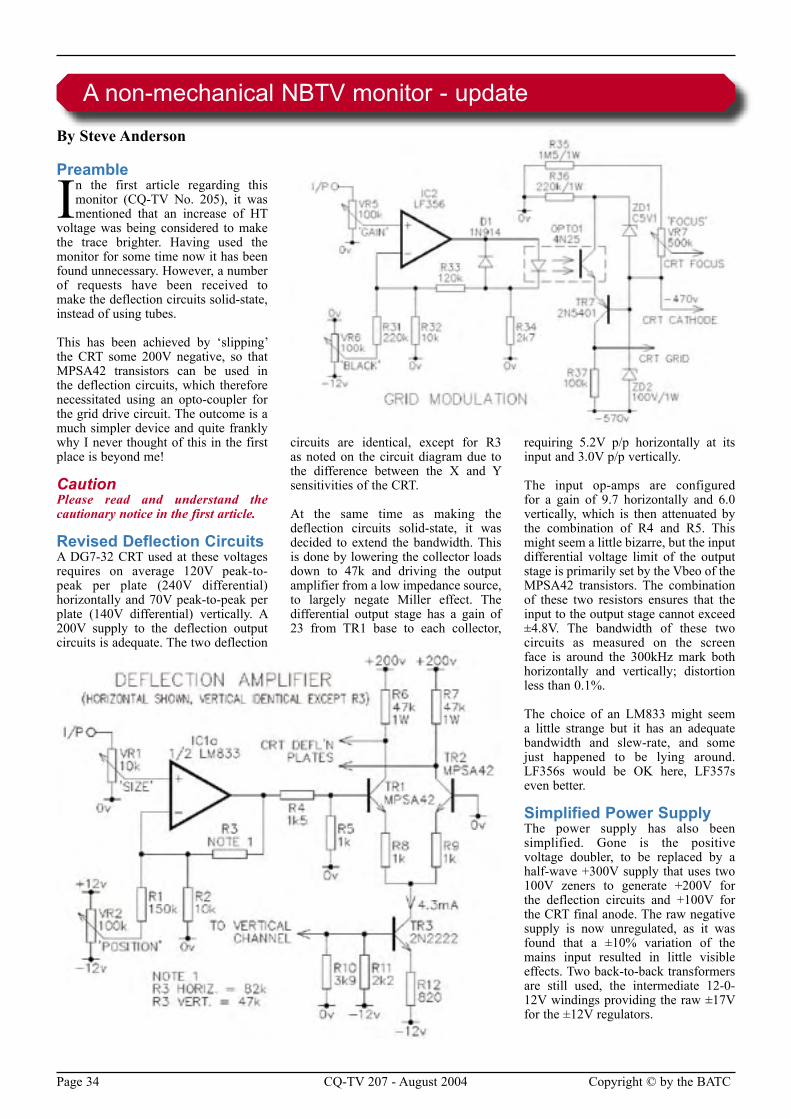
Page 34 CQ-TV 207 - August 2004 Copyright © by the BATC
By Steve Anderson
Preamble
In the first article regarding this monitor (CQ-TV No. 205), it was mentioned that an increase of HT
voltage was being considered to make the trace brighter. Having used the monitor for some time now it has been found unnecessary. However, a number of requests have been received to make the deflection circuits solid-state, instead of using tubes.
This has been achieved by ‘slipping’ the CRT some 200V negative, so that MPSA42 transistors can be used in the deflection circuits, which therefore necessitated using an opto-coupler for the grid drive circuit. The outcome is a much simpler device and quite frankly why I never thought of this in the first place is beyond me!
CautionPlease read and understand the cautionary notice in the first article.
Revised Deflection CircuitsA DG7-32 CRT used at these voltages requires on average 120V peak-to-peak per plate (240V differential) horizontally and 70V peak-to-peak per plate (140V differential) vertically. A 200V supply to the deflection output circuits is adequate. The two deflection
circuits are identical, except for R3 as noted on the circuit diagram due to the difference between the X and Y sensitivities of the CRT.
At the same time as making the deflection circuits solid-state, it was decided to extend the bandwidth. This is done by lowering the collector loads down to 47k and driving the output amplifier from a low impedance source, to largely negate Miller effect. The differential output stage has a gain of 23 from TR1 base to each collector,
requiring 5.2V p/p horizontally at its input and 3.0V p/p vertically.
The input op-amps are configured for a gain of 9.7 horizontally and 6.0 vertically, which is then attenuated by the combination of R4 and R5. This might seem a little bizarre, but the input differential voltage limit of the output stage is primarily set by the Vbeo of the MPSA42 transistors. The combination of these two resistors ensures that the input to the output stage cannot exceed ±4.8V. The bandwidth of these two circuits as measured on the screen face is around the 300kHz mark both horizontally and vertically; distortion less than 0.1%.
The choice of an LM833 might seem a little strange but it has an adequate bandwidth and slew-rate, and some just happened to be lying around. LF356s would be OK here, LF357s even better.
Simplified Power SupplyThe power supply has also been simplified. Gone is the positive voltage doubler, to be replaced by a half-wave +300V supply that uses two 100V zeners to generate +200V for the deflection circuits and +100V for the CRT final anode. The raw negative supply is now unregulated, as it was found that a ±10% variation of the mains input resulted in little visible effects. Two back-to-back transformers are still used, the intermediate 12-0-12V windings providing the raw ±17V for the ±12V regulators.
A non-mechanical NBTV monitor - update
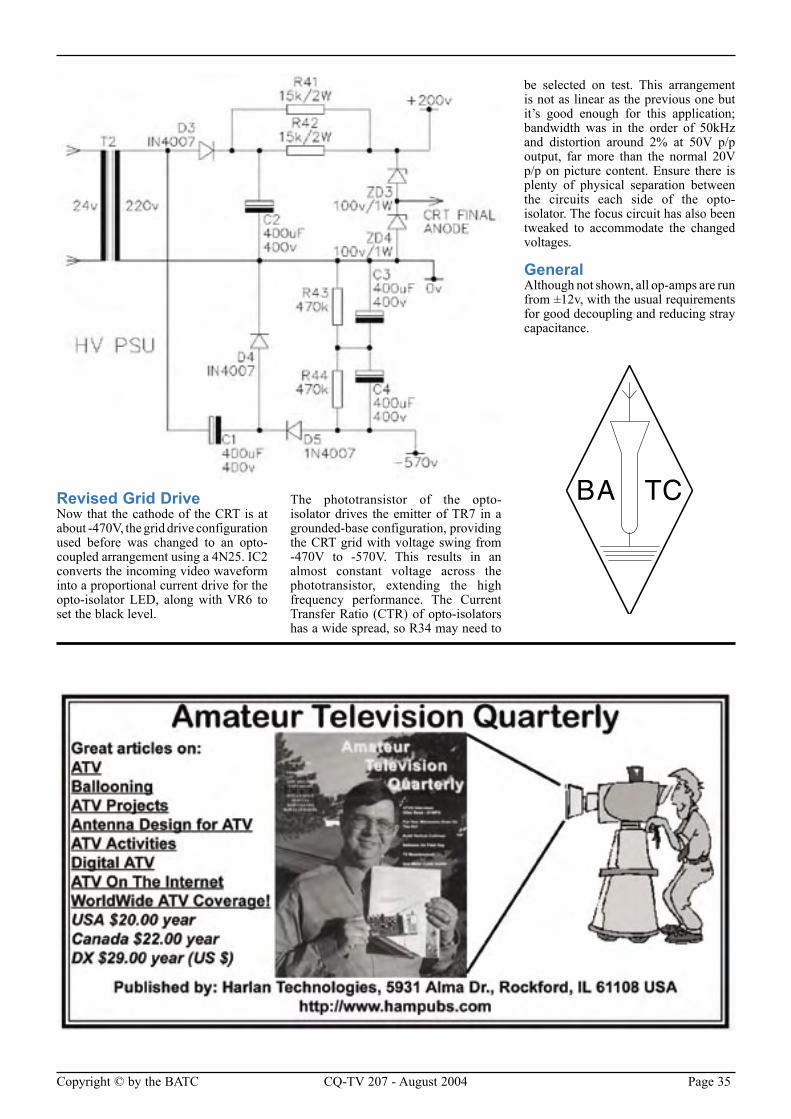
Copyright © by the BATC CQ-TV 207 - August 2004 Page 35
Revised Grid DriveNow that the cathode of the CRT is at about -470V, the grid drive configuration used before was changed to an opto-coupled arrangement using a 4N25. IC2 converts the incoming video waveform into a proportional current drive for the opto-isolator LED, along with VR6 to set the black level.
The phototransistor of the opto-isolator drives the emitter of TR7 in a grounded-base configuration, providing the CRT grid with voltage swing from -470V to -570V. This results in an almost constant voltage across the phototransistor, extending the high frequency performance. The Current Transfer Ratio (CTR) of opto-isolators has a wide spread, so R34 may need to
be selected on test. This arrangement is not as linear as the previous one but it’s good enough for this application; bandwidth was in the order of 50kHz and distortion around 2% at 50V p/p output, far more than the normal 20V p/p on picture content. Ensure there is plenty of physical separation between the circuits each side of the opto-isolator. The focus circuit has also been tweaked to accommodate the changed voltages.
GeneralAlthough not shown, all op-amps are run from ±12v, with the usual requirements for good decoupling and reducing stray capacitance.
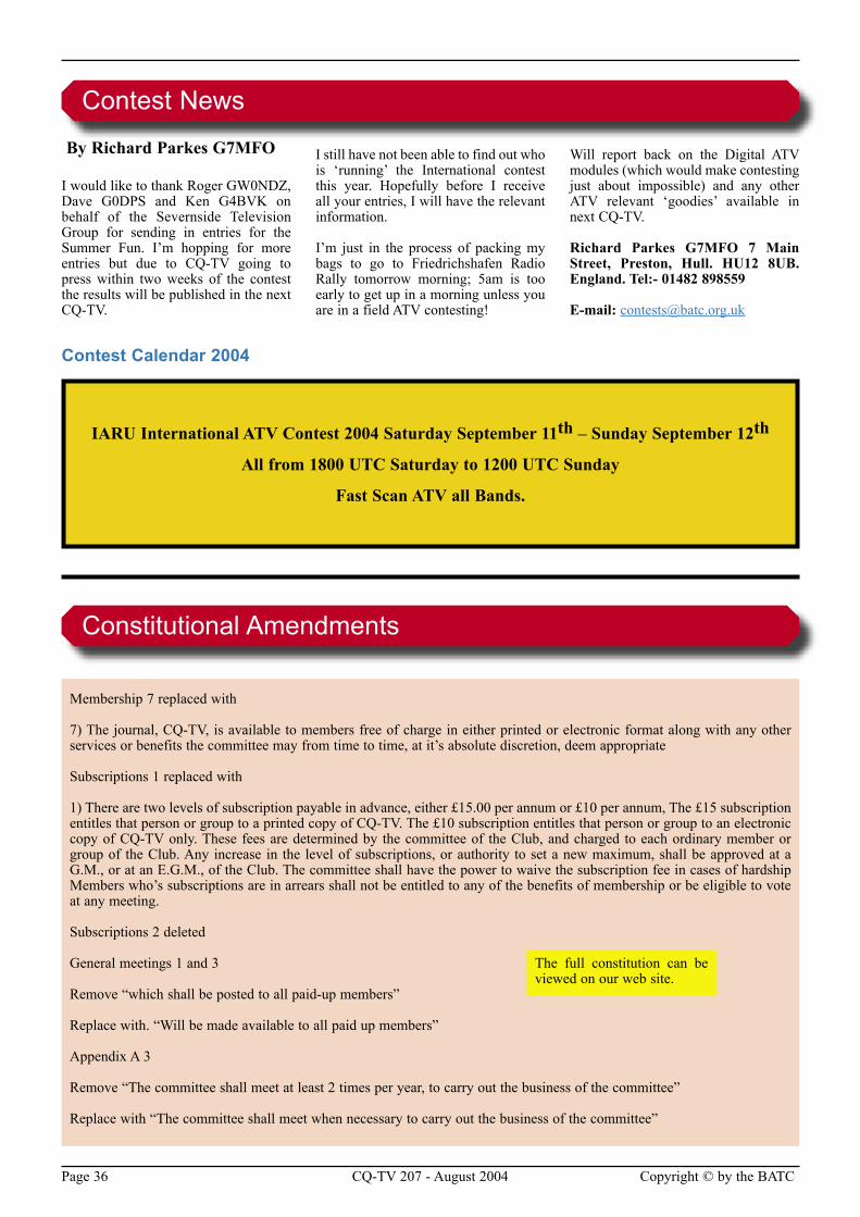
Page 36 CQ-TV 207 - August 2004 Copyright © by the BATC
By Richard Parkes G7MFO
I would like to thank Roger GW0NDZ, Dave G0DPS and Ken G4BVK on behalf of the Severnside Television Group for sending in entries for the Summer Fun. I’m hopping for more entries but due to CQ-TV going to press within two weeks of the contest the results will be published in the next CQ-TV.
I still have not been able to find out who is ‘running’ the International contest this year. Hopefully before I receive all your entries, I will have the relevant information.
I’m just in the process of packing my bags to go to Friedrichshafen Radio Rally tomorrow morning; 5am is too early to get up in a morning unless you are in a field ATV contesting!
Will report back on the Digital ATV modules (which would make contesting just about impossible) and any other ATV relevant ‘goodies’ available in next CQ-TV.
Richard Parkes G7MFO 7 Main Street, Preston, Hull. HU12 8UB. England. Tel:- 01482 898559
E-mail: [email protected]
IARU International ATV Contest 2004 Saturday September 11th – Sunday September 12th
All from 1800 UTC Saturday to 1200 UTC Sunday
Fast Scan ATV all Bands.
Contest News
Contest Calendar 2004
Membership 7 replaced with
7) The journal, CQ-TV, is available to members free of charge in either printed or electronic format along with any other services or benefits the committee may from time to time, at it’s absolute discretion, deem appropriate
Subscriptions 1 replaced with
1) There are two levels of subscription payable in advance, either £15.00 per annum or £10 per annum, The £15 subscription entitles that person or group to a printed copy of CQ-TV. The £10 subscription entitles that person or group to an electronic copy of CQ-TV only. These fees are determined by the committee of the Club, and charged to each ordinary member or group of the Club. Any increase in the level of subscriptions, or authority to set a new maximum, shall be approved at a G.M., or at an E.G.M., of the Club. The committee shall have the power to waive the subscription fee in cases of hardship Members who’s subscriptions are in arrears shall not be entitled to any of the benefits of membership or be eligible to vote at any meeting.
Subscriptions 2 deleted
General meetings 1 and 3
Remove “which shall be posted to all paid-up members”
Replace with. “Will be made available to all paid up members”
Appendix A 3
Remove “The committee shall meet at least 2 times per year, to carry out the business of the committee”
Replace with “The committee shall meet when necessary to carry out the business of the committee”
Constitutional Amendments
The full constitution can be viewed on our web site.
Copyright © by the BATC CQ-TV 207 - August 2004 Page 37
By John Stockley, G8MNY
Many satellite receivers give good service for ATV work after some modifications.
Here are some typical symptoms and problems with there use for ATV.
With weak signals a typical satellite receiver will receive the sound first, then colour information, and lastly a locked picture - whereas a dedicated narrower ATV receiver will receive a black and white picture first, then the colour, and the sound last, but all at a much lower signal level. Radar overload and look-though overload from your transmitter are also less troublesome with a proper receiver than a satellite receiver.
Typical problems
RF1) If the coax is permanently or unsafely powered, some receivers would blow up on shorting!
2) Many receivers are very insensitive, as they are designed for a 50dB gain LNB input level.
3) The untuned, 1 GHz, wide front end lets lots of unwanted noise through to the mixer stage, where it can degrade the wanted signal.
4) RF stages are easily overloaded, as the receiver is designed for a band full of the same strength signals, and of limited level range.
5) Image noise and QRM can be a problem with a wide, lightly filtered, front end. eg. TV signals on 470 - 800MHz and cellphones systems on 0.9, 1.8, 2.7GHz etc.
6) The 30MHz wide IF lets too much bandwidth through for ATV, and often with not much skirt rejection of adjacent frequencies.
7) There is a permanent wide locking AFC, which is not designed for weak signals.
8) The FM discriminator circuit is not optimised for narrow deviation.
Video9) This is set up for wide deviation, so the video gain needs to be 2-3x for ATV to give a 1V output.
10) A poor LF response, to remove 25Hz energy dispersal satellite signals, causes corruption of frame syncs on ATV. This is sometimes also caused by too fast an AFC.
11) Sometimes the proper CCIR 405 de-emphasis curve is not used.
12) The video needs 6 MHz traps, to reduce sub-carrier patterning.
Sound13) The sound IF needs to be set for 6 MHz.
These problems not only occur with satellite receivers, but on many dedicated 23cm ATV receiver designs using satellite modules as well. Digital satellite receivers also suffer from the same RF shortcomings, but you will never know the cause of problem as they just won’t work!
Tips on possible solutionsNot all of these solutions can be applied to small modern receivers; the bigger older ones lend themselves to modification much better, but you will need a diagram and a good understanding of how the circuit works!
1) The +12 or +18V is useful for powering preamps, but an 18V 2W lamp or a 47R 5W resistor in series with the first supply pin to the satellite receiver RF box is recommended to stop accidents and allow short circuit aerials in safety.
2) Insensitivity can be masked with a low noise high gain preamp (eg 1dB NF and 40dB gain), but the amplified noise floor from the preamp should exceed the receiver noise floor by around 10dB. This is because less preamp gain than this will show up the receiver noise and more will reduce the overload threshold point.
3) A well filtered GaAsfet preamp will help, or use a good inter-digital filter peaked on the wanted frequency eg your local repeater output. [2] [3]
4a) For radar overloads, try a good inter-digital filter, reduce the preamp gain, and even use a video radar clipper. A suckout filter is not usually any good, as radars often use 4 frequencies at once. [2] [3] [1]
4b) For look-through blocked by your transmitter, try a good inter-digital or suckout filter; also try reducing the preamp gain. [2] [3] [4] [5]
5) Again, for unwanted images, use filters before the satellite receiver. [2] [3] [4] [5]
6) Halving the IF bandwidth will reduce the noise and eliminate much of the nearby radar seen by the demodulator, thus improving the signal. However, only a re-tweaked IF filter can do this job, and for a receiver with fixed IF filters this is not a option. Unfortunately, this means that narrowing the bandwidth is not possible on many receiver designs!
Too narrow an IF will eventually loose sound and colour, and give sparkly edges and syncs. Due to the FM capture effect, a noisy P1 picture with heavy radar on a wide bandwidth receiver can be a P3 with little radar on a narrow receiver.
Any reduced colour and sound sub-carrier levels from the video demodulator due to the narrowed IF can be compensated for with less de-emphasis and a 6MHz IF preamp, as the baseband video noise floor around these sub-carriers is also reduced.
7) Add a defeat AFC switch before trying more complex AFC systems. Ideally the AFC needs to be a sync tip detecting type for narrow IFs. [6]
8) Depending on the demodulator design (PLL/discriminator) try different resistors for the loop values, or retuning the discriminator coils to give a better performance.
9) Turn up any video gain preset or modify the video amplifier for 2-3x gain to get a 1V p-p terminated output, with a correctly modulated source.
10) Poor LF response is a problem as video needs a zero phase change at 50Hz so the lowest frequency needs to be 10Hz. Change any small capacitors handling video for bigger values, eg. 47uF to 470uF into a 75 ohms load.
If the AFC is too fast, it can be slowed down by increasing the capacitor values, so that the AFC control line does not include video frequencies.
What’s wrong with Analogue Satellite Receivers for ATV?
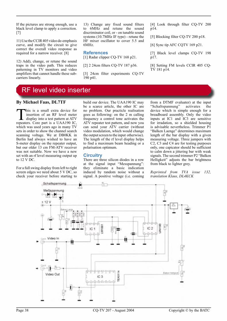
Page 38 CQ-TV 207 - August 2004 Copyright © by the BATC
If the pictures are strong enough, use a black level clamp to apply a correction. [7]
11) Use the CCIR 405 video de-emphasis curve, and modify the circuit to give correct the overall video response as required for a narrow receiver. [8]
12) Add), change, or retune the sound traps in the video path. This reduces patterning in TV monitors and video amplifiers that cannot handle these sub-carriers linearly.
13) Change any fixed sound filters to 6MHz and retune the sound discriminator coil, or - on tunable sound systems (10.7MHz IF type) - retune the HF mixer oscillator to cover 5.5 and 6MHz.
References[1] Radar clipper CQ-TV 168 p21.
[2] 2 24cm filters CQ-TV 187 p36.
[3] 24cm filter experiments CQ-TV 190 p41.
[4] Look through filter CQ-TV 200 p14.
[5] Blocking filter CQ-TV 200 p18.
[6] Sync tip AFC CQTV 169 p21.
[7] Black level clamps CQ-TV 198 p17.
[8] Setting FM levels CCIR 405 CQ-TV 181 p14.
By Michael Faas, DL7TF
This is a small extra device for insertion of an RF level meter display into a test pattern at ATV
repeaters. Core part is a UAA190 IC, which was used years ago in many TV sets in order to show the channel search scanning voltage. We at DB0KK in Berlin had always wished to have an S-meter display on the repeater output, but our older 13 cm FM-ATV receiver was not suitable. Now we have a new set with an rf level measuring output up to 12 V DC.
For a full swing display from left to right screen edges we need about 5 V DC, so check your receiver before starting to
build our device. The UAA190 IC may be a scarce article, the other IC are no problem. Our practicle realisation goes as following: on the 2 m calling frequency a control tone activates the ATV repeater test pattern, and now you can send your ATV carrier (without video modulation, which would change the output screen to the input otherwise). The length of the rf level display helps to find a maximum beam heading or a polarisation optimum.
CircuitryThere are three silicon diodes in a row at the signal input “Messpannung”: they eliminate a basic indication induced by random noise without a signal. A positive voltage (i.e. coming
from a DTMF evaluater) at the input “Schaltspannung” activates the device which is simple enough for a breadboard assembly. Only the video inputs at IC1 and IC3 are sensitive for irradation, so a shielded housing is advisable nevertheless. Trimmer P1 “Balken Laenge” determines maximum length of the bar display with a given measuring voltage. Three jumpers with C2, C3 and C4 are for testing purposes only, one capicator should be sufficient to calm down a jittering bar with weak signals. The second trimmer P2 “Balken Helligkeit” adjusts the bar brightness from black to lighter grey.
Reprinted from TVA issue 132, translation Klaus, DL4KCK
RF level video inserter
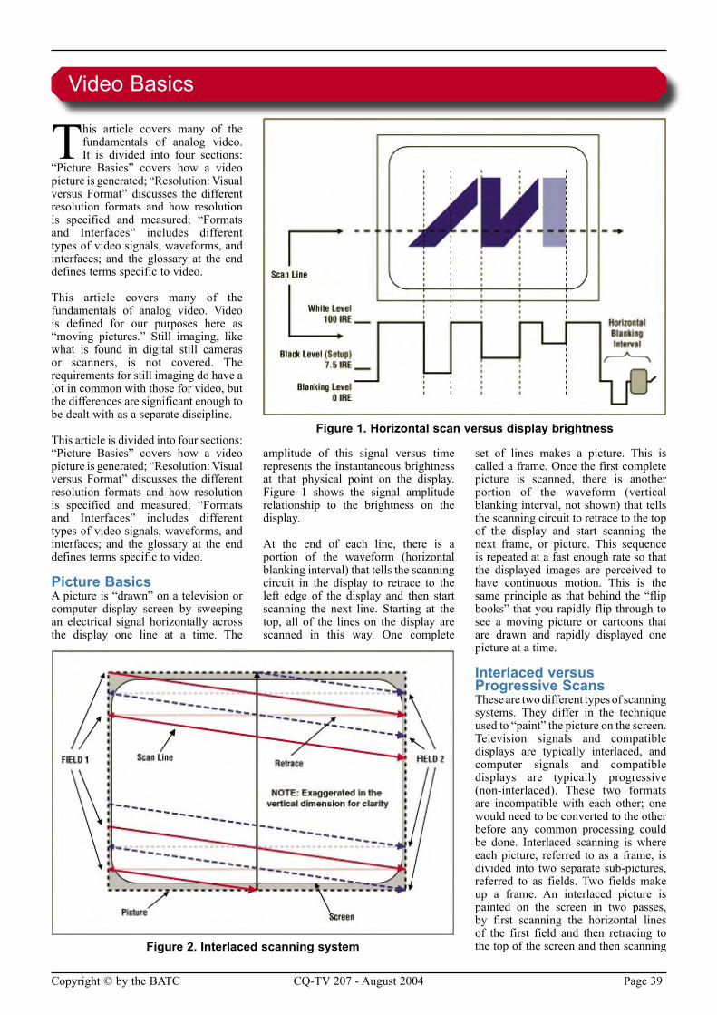
Copyright © by the BATC CQ-TV 207 - August 2004 Page 39
This article covers many of the fundamentals of analog video. It is divided into four sections:
“Picture Basics” covers how a video picture is generated; “Resolution: Visual versus Format” discusses the different resolution formats and how resolution is specified and measured; “Formats and Interfaces” includes different types of video signals, waveforms, and interfaces; and the glossary at the end defines terms specific to video.
This article covers many of the fundamentals of analog video. Video is defined for our purposes here as “moving pictures.” Still imaging, like what is found in digital still cameras or scanners, is not covered. The requirements for still imaging do have a lot in common with those for video, but the differences are significant enough to be dealt with as a separate discipline.
This article is divided into four sections: “Picture Basics” covers how a video picture is generated; “Resolution: Visual versus Format” discusses the different resolution formats and how resolution is specified and measured; “Formats and Interfaces” includes different types of video signals, waveforms, and interfaces; and the glossary at the end defines terms specific to video.
Picture BasicsA picture is “drawn” on a television or computer display screen by sweeping an electrical signal horizontally across the display one line at a time. The
amplitude of this signal versus time represents the instantaneous brightness at that physical point on the display. Figure 1 shows the signal amplitude relationship to the brightness on the display.
At the end of each line, there is a portion of the waveform (horizontal blanking interval) that tells the scanning circuit in the display to retrace to the left edge of the display and then start scanning the next line. Starting at the top, all of the lines on the display are scanned in this way. One complete
set of lines makes a picture. This is called a frame. Once the first complete picture is scanned, there is another portion of the waveform (vertical blanking interval, not shown) that tells the scanning circuit to retrace to the top of the display and start scanning the next frame, or picture. This sequence is repeated at a fast enough rate so that the displayed images are perceived to have continuous motion. This is the same principle as that behind the “flip books” that you rapidly flip through to see a moving picture or cartoons that are drawn and rapidly displayed one picture at a time.
Interlaced versus Progressive ScansThese are two different types of scanning systems. They differ in the technique used to “paint” the picture on the screen. Television signals and compatible displays are typically interlaced, and computer signals and compatible displays are typically progressive (non-interlaced). These two formats are incompatible with each other; one would need to be converted to the other before any common processing could be done. Interlaced scanning is where each picture, referred to as a frame, is divided into two separate sub-pictures, referred to as fields. Two fields make up a frame. An interlaced picture is painted on the screen in two passes, by first scanning the horizontal lines of the first field and then retracing to the top of the screen and then scanning
Video Basics
Figure 1. Horizontal scan versus display brightness
Figure 2. Interlaced scanning system
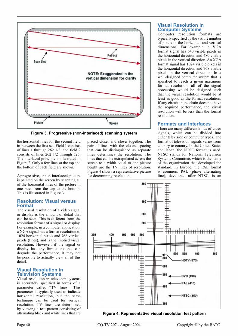
Page 40 CQ-TV 207 - August 2004 Copyright © by the BATC
the horizontal lines for the second field in-between the first set. Field 1 consists of lines 1 through 262 1/2, and field 2 consists of lines 262 1/2 through 525. The interlaced principle is illustrated in Figure 2. Only a few lines at the top and the bottom of each field are shown.
A progressive, or non-interlaced, picture is painted on the screen by scanning all of the horizontal lines of the picture in one pass from the top to the bottom. This is illustrated in Figure 3.
Resolution: Visual versus FormatThe visual resolution of a video signal or display is the amount of detail that can be seen. This is different from the resolution format of a signal or display. For example, in a computer application, a XGA signal has a format resolution of 1024 horizontal pixels and 768 vertical pixels (lines), and is the implied visual resolution. However, if the signal or display has any limitations that can degrade the performance, it may not be possible to actually view all of this detail.
Visual Resolution in Television SystemsVisual resolution in television systems is accurately specified in terms of a parameter called “TV lines.” This parameter is typically used to indicate horizontal resolution, but the same technique can be used for vertical resolution. TV lines are determined by viewing a test pattern consisting of alternating black and white lines that are
placed closer and closer together. The pair of lines with the closest spacing that can be distinguished as separate lines determines the resolution. The lines that can be extrapolated across the screen to a width equal to one picture height are the TV lines of resolution. Figure 4 shows a representative picture for determining resolution.
Visual Resolution in Computer SystemsComputer resolution formats are typically specified by the visible number of pixels in the horizontal and vertical dimensions. For example, a VGA format signal has 640 visible pixels in the horizontal direction and 480 visible pixels in the vertical direction. An XGA format signal has 1024 visible pixels in the horizontal direction and 768 visible pixels in the vertical direction. In a well-designed computer system that is specified to reach a given maximum format resolution, all of the signal processing would be designed such that the visual resolution would be at least as good as the format resolution. If any circuit in the chain does not have the required performance, the visual resolution will be less than the format resolution.
Formats and InterfacesThere are many different kinds of video signals, which can be divided into either television or computer types. The format of television signals varies from country to country. In the United States and Japan, the NTSC format is used. NTSC stands for National Television Systems Committee, which is the name of the organization that developed the standard. In Europe, the PAL format is common. PAL (phase alternating line), developed after NTSC, is an
Figure 3. Progressive (non-interlaced) scanning system
Figure 4. Representative visual resolution test pattern
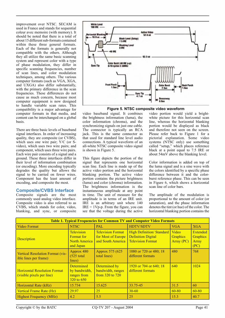
Copyright © by the BATC CQ-TV 207 - August 2004 Page 41
improvement over NTSC. SECAM is used in France and stands for sequential coleur avec memoire (with memory). It should be noted that there is a total of about 15 different sub-formats contained within these three general formats. Each of the formats is generally not compatible with the others. Although they all utilize the same basic scanning system and represent color with a type of phase modulation, they differ in specific scanning frequencies, number of scan lines, and color modulation techniques, among others. The various computer formats (such as VGA, XGA, and UXGA) also differ substantially, with the primary difference in the scan frequencies. These differences do not cause as much concern, because most computer equipment is now designed to handle variable scan rates. This compatibility is a major advantage for computer formats in that media, and content can be interchanged on a global basis.
There are three basic levels of baseband signal interfaces. In order of increasing quality, they are composite (or CVBS), which uses one wire pair; Y/C (or S-video), which uses two wire pairs; and component, which uses three wire pairs. Each wire pair consists of a signal and a ground. These three interfaces differ in their level of information combination (or encoding). More encoding typically degrades the quality but allows the signal to be carried on fewer wires. Component has the least amount of encoding, and composite the most.
Composite/CVBS InterfaceComposite signals are the most commonly used analog video interface. Composite video is also referred to as CVBS, which stands for color, video, blanking, and sync, or composite
video baseband signal. It combines the brightness information (luma), the color information (chroma), and the synchronizing signals on just one cable. The connector is typically an RCA jack. This is the same connector as that used for standard line level audio connections. A typical waveform of an all-white NTSC composite video signal is shown in Figure 5.
This figure depicts the portion of the signal that represents one horizontal scan line. Each line is made up of the active video portion and the horizontal blanking portion. The active video portion contains the picture brightness (luma) and color (chroma) information. The brightness information is the instantaneous amplitude at any point in time. The unit of measure for the amplitude is in terms of an IRE unit. IRE is an arbitrary unit where 140 IRE = 1Vp-p. From the figure, you can see that the voltage during the active
video portion would yield a bright-white picture for this horizontal scan line, whereas the horizontal blanking portion would be displayed as black and therefore not seen on the screen. Please refer back to Figure 1 for a pictorial explanation. Some video systems (NTSC only) use something called “setup,” which places reference black at a point equal to 7.5 IRE or about 54mV above the blanking level.
Color information is added on top of the luma signal and is a sine wave with the colors identified by a specific phase difference between it and the color-burst reference phase. This can be seen in Figure 6, which shows a horizontal scan line of color bars.
The amplitude of the modulation is proportional to the amount of color (or saturation), and the phase information denotes the tint (or hue) of the color. The horizontal blanking portion contains the
Figure 5. NTSC composite video waveform
Table 1. Typical Frequencies for Common TV and Computer Video FormatsVideo Format NTSC PAL HDTV/SDTV VGA XGA
Description
Television Format for North America and Japan
Television Format for Most of Europe and South America
High Definition/ Standard Definition Digital Television Format
Video Graphics Array (PC)
Extended Graphics Array (PC)
Vertical Resolution Format (vis-ible lines per frame)
Approx 480 (525 total lines)
Approx 575 (625 total lines)
1080 or 720 or 480; 18 different formats
480 768
Horizontal Resolution Format (visible pixels per line)
Determined by bandwidth, ranges from 320 to 650
Determined by bandwidth, ranges from 320 to 720
1920 or 704 or 640; 18 different formats
640 1024
Horizontal Rate (kHz) 15.734 15.625 33.75-45 31.5 60Vertical Frame Rate (Hz) 29.97 25 30-60 60-80 60-80Highest Frequency (MHz) 4.2 5.5 25 15.3 40.7
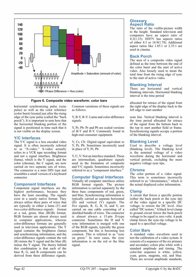
Page 42 CQ-TV 207 - August 2004 Copyright © by the BATC
horizontal synchronizing pulse (sync pulse) as well as the color reference (color burst) located just after the rising edge of the sync pulse (called the “back porch”). It is important to note here that the horizontal blanking portion of the signal is positioned in time such that it is not visible on the display screen.
Y/C InterfacesThe Y/C signal is a less encoded video signal. It is often incorrectly referred to as “S-video.” S-video actually refers to a VCR tape recording format and not a signal interface. Brightness (luma), which is the Y signal, and the color (chroma), the C signal, are now carried on two separate sets of wires. The connector is a mini DIN type and resembles a small version of a keyboard connector.
Component InterfacesComponent signal interfaces are the highest performance, because they have the least encoding. The signals exist in a nearly native format. They always utilize three pairs of wires that are typically in either a luma (Y) and two-color-difference-signals format or a red, green, blue (RGB) format. RGB formats are almost always used in computer applications, whereas color-difference formats are generally used in television applications. The Y signal contains the brightness (luma) and synchronizing information, and the color-difference signals contain the red (R) minus the Y signal and the blue (B) minus the Y signal. The theory behind this combination is that each of the base R, G, and B components can be derived from these difference signals.
Common variations of these signals are as follows:
Y, B-Y, R-Y: Luma and color-difference signals.
Y, Pr, Pb: Pr and Pb are scaled versions of B-Y and R-Y. Commonly found in high-end consumer equipment.
Y, Cr, Cb: Digital-signal equivalent to Y, Pr, Pb. Sometimes incorrectly used in place of Y, Pr, Pb.
Y, U, V: Not an interface standard. These are intermediate, quadrature signals used in the formation of composite and Y/C signals. Sometimes incorrectly referred to as a “component interface.”
Computer Signal InterfacesVirtually all computer interfaces utilize RGB format signals. The picture information is carried separately by the three base components of red, green, and blue. Synchronizing information is typically carried as separate horizontal (H) and vertical (V) signals. The five signals, R, G, B, H, and V, are carried on one cable consisting of a shielded bundle of wires. The connector is almost always a 15-pin D-type connector. Sometimes the H and V sync information is merged with one of the RGB signals, typically the green component, but this is becoming less common. This is referred to as “sync on green.” In rarer cases, the sync information is on the red or the blue signal.
Glossary Aspect Ratio The ratio of the visible-picture width to the height. Standard television and computers have an aspect ratio of 4:3(1.33). HDTV has aspects ratios of either 4:3 or 16:9(1.78). Additional aspect ratios like 1.85:1 or 2.35:1 are used in cinema.
Back Porch The area of a composite video signal defined as the time between the end of the color burst and the start of active video. Also loosely used to mean the total time from the rising edge of sync to the start of active video.
Blanking Interval There are horizontal and vertical blanking intervals. Horizontal blanking interval is the time period
allocated for retrace of the signal from the right edge of the display back to the left edge to start another
scan line. Vertical blanking interval is the time period allocated for retrace of the signal from the bottom back to the top to start another field or frame. Synchronizing signals occupy a portion of the blanking interval.
Blanking Level Used to describe a voltage level (blanking level). The blanking level is the nominal voltage of a video waveform during the horizontal and vertical periods, excluding the more negative voltage sync tips.
Chroma The color portion of a video signal. This term is sometimes incorrectly referred to as “chrominance,” which is the actual displayed color information.
Clamp A circuit that forces a specific portion (either the back porch or the sync tip) of the video signal to a specific DC voltage, to restore the DC level. Also called “DC restore.” A black level clamp to ground circuit forces the back-porch voltage to be equal to zero volts. A peak clamp forces the sync-tip voltage to be equal to a specified voltage.
Color Bars A standard video waveform used to test the calibration of a video system. It consists of a sequence of the six primary and secondary colors plus white with a standard amplitude and timing. The color-bar sequence is white, yellow, cyan, green, magenta, red, and blue. There are several amplitude standards,
Figure 6. Composite video waveform: color bars
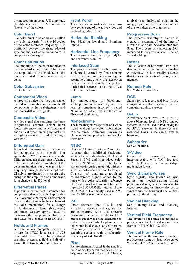
Copyright © by the BATC CQ-TV 207 - August 2004 Page 43
the most common being 75% amplitude (brightness) with 100% saturation (intensity of the color).
Color Burst The color burst, also commonly called the “color subcarrier,” is 8 to 10 cycles of the color reference frequency. It is positioned between the rising edge of sync and the start of active video for a composite video signal.
Color Saturation The amplitude of the color modulation on a standard video signal. The larger the amplitude of this modulation, the more saturated (more intense) the color.
Color Subcarrier See Color Burst.
Component Video A three-wire video interface that carries the video information in its basic RGB components or luma (brightness) and two-color-difference signals.
Composite Video A video signal that combines the luma (brightness), chroma (color), burst (color reference), and sync (horizontal and vertical synchronizing signals) into a single waveform carried on a single wire pair.
Differential Gain Important measurement parameter for composite video signals. Not applicable in Y/C or component signals. Differential gain is the amount of change in the color saturation (amplitude of the color modulation) for a change in low-frequency luma (brightness) amplitude. Closely approximated by measuring the change in the amplitude of a sine wave for a change in its DC level.
Differential Phase Important measurement parameter for composite video signals. Not applicable in Y/C or component signals. Differential phase is the change in hue (phase of the color modulation) for a change in lowfrequency luma (brightness) amplitude. Closely approximated by measuring the change in the phase of a sine wave for a change in its DC level.
Fields and Frames A frame is one complete scan of a picture. In NTSC it consists of 525 horizontal scan lines. In interlaced scanning systems, a field is half of a frame; thus, two fields make a frame.
Front Porch The area of a composite video waveform between the end of the active video and the leading edge of sync.
Horizontal Blanking See Blanking Level and Blanking Interval.
Horizontal Line Frequency The inverse of the time (or period) for one horizontal scan line.
Interlaced Scan The process whereby each frame of a picture is created by first scanning half of the lines and then scanning the second set of lines, which are interleaved between the first to complete the picture. Each half is referred to as a field. Two fields make a frame.
Luma The monochrome or black-and-white portion of a video signal. This term is sometimes incorrectly called “luminance,” which refers to the actual displayed brightness.
Monochrome The luma (brightness) portion of a video signal without the color information. Monochrome, commonly known as black-and-white, predates current color television.
NTSCNational Television Systems Committee. A group that established black-and-white television standards in the United States in 1941 and later added color in 1953. NTSC is used to refer to the systems and signals compatible with this specific color-modulation technique. Consists of quadrature-modulated colordifference signals added to the luma with a color subcarrier reference of 455/2 times the horizontal line rate, typically 3.579545MHz with an H rate of 15.75kHz. Commonly used in 525-line, 59.94Hz scanning systems.
PALPhase alternate line. PAL is used to refer to systems and signals that are compatible with this specific modulation technique. Similar to NTSC but uses subcarrier phase alternation to reduce the sensitivity to phase errors that would be displayed as color errors. Commonly used with 626-line, 50Hz scanning systems with a subcarrier frequency of 4.43362MHz.
PixelPicture element. A pixel is the smallest piece of display detail that has a unique brightness and color. In a digital image,
a pixel is an individual point in the image, represented by a certain number of bits to indicate the brightness.
Progressive Scan The process whereby a picture is created by scanning all of the lines of a frame in one pass. See also Interlaced Scan. The process of converting from interlaced to progressive scan is called “line doubling.”
Raster The collection of horizontal scan lines that makes up a picture on a display. A reference to it normally assumes that the sync elements of the signal are included.
Refresh Rate See Vertical Frame Rate.
RGB Stands for red, green, and blue. It is a component interface typically used in computer graphics systems.
Setup A reference black level 7.5% (7.5IRE) above blanking level in NTSC analog systems. It is not used in PAL or digital or HDTV systems. In these systems, reference black is the same level as blanking.
SubcarrierSee Color Burst.
S-Video Commonly incorrectly used interchangeably with Y/C. See also Y/C. Technically, a magnetic-tape modulation format.
Sync Signals/PulsesSync signals, also known as sync pulses, are negative-going timing pulses in video signals that are used by video-processing or display devices to synchronize the horizontal and vertical portions of the display.
Vertical Blanking See Blanking Level and Blanking Interval.
Vertical Field Frequency The inverse of the time (or period) to produce one field of video (half of a frame). In NTSC it is 59.94Hz.
Vertical Frame Rate The inverse of the time (or period) to produce one frame of video. Also called “refresh rate” or “vertical refresh rate.”
Page 44 CQ-TV 207 - August 2004 Copyright © by the BATC
Dicky Howett confesses to being slightly injudicious.
Recently I had occasion to rail against the continuing inaccuracies of website television
histories. It seems that, arguably, I have been guilty myself of the same fault i.e.; of spreading an historical television inaccuracy. Or so it would appear.
In an article of mine (published elsewhere) entitled ironically, ‘Don’t Let The Facts Get In The Way’, I berated a poor, unfortunate website TV ‘historian’ for re-telling a John Logie Baird ‘TV story’ and treating it as fact. This TV tale recounts the 1926 Frith Street demonstration-- to members of the Royal Institution-- at which an elderly scientist got his long white beard caught in the whizzing machinery. I stated that this story was nothing but an amusing fiction. Baird would never have exposed important persons to the dangers of moving parts. It’s recorded that Baird had suffered previously, partial disintegration of his ‘camera’ when spinning components became unglued and rocketed around the lab at high speed. During the Frith Street demonstration, Baird’s entire apparatus was covered by cloths and sheets. The use of such ‘protection’ would have been essential to Baird who was fully aware of the competitive ‘race’ to achieve television and thus would not have exposed his techniques fully to the glare of potential competitors. Also, Baird on this occasion, was using (or so it is alleged) a known image scanning technique called the flying spot. Albert Abramson in his book, ‘The History of Television 1888-1941.’ mentions Baird’s flying spot technique,
“On January 26th 1926, Baird gave a demonstration of his television apparatus to some 40 members of the Royal Institution at his laboratory in Frith Street, Soho. All of Baird’s
publicity indicated that Baird had invented a super-sensitive photocell which he kept a secret. No one ever saw his transmitter or his cell. His apparatus was always covered with screens of one sort or another, with the excuse that “extraneous light was not wanted and would interfere with the image.” There was even a story that Baird had been experimenting with a cell made of visual purple, which was nonsense. It was also claimed that Baird had invented some “exotic” circuit using a transformer that magically solved his problems. Later it was stated that Baird was very frightened of industrial espionage, but it would be more truthful to indicate that Baird and his financial backers wanted to keep his simple (but most effective) method a secret for as long as possible in order to head off any possible competition. For it was soon realised that the “flying spot system,” while patentable, could not be protected.”
The above extract is to a degree contradicted by R.W.Burns in his book ‘British Television-The Formative Years’. The extracts reproduced below clearly don’t describe a flying spot system. Burns writes,
“Following the demonstration at Frith Street to members of the Royal Institution, arrangements were made for a private demonstration to be given to a Mr E.G. Stewart. Mr Stewart’s very interesting report, written in April 1926, only came to light in 1948. Stewart, a perspicacious engineer, was able to describe and give details of the equipment and impressions which were not mentioned by The Times reporter.
“The subject, which in the demonstration was limited to a size about 10 inch x 8 inch is brightly illuminated, about 500 candle power being used at one foot distance, and placed before an optical device of revolving lenses which continuously explores the whole surface
in 32 vertical bands, each ¼ inch width is thus treated as being uniform…. at the demonstration the received image was one ninth the area of the subject being 3 1/2 inch x 2 1/2 inch before magnification.”
E.G.Stewart went on to describe the quality of reproduction:
“I found it possible to distinguish between two human faces I had previously seen in the life whilst opening and closing of the mouth, protrusion of the tongue, orientation or the head and passing of the hand over the face could clearly be followed. At the same time it would be very difficult to recognise an individual previously unknown from the television representation. The inventor agreed however that the image was distorted and attributed it to, (1), inferior optical equipment and, (2) to insufficient sub-division of the pictures. He assured me that his lenses now were only lantern condensers and cycle lamp bull’s eyes. This would certainly not add clarity to the picture and it would be interesting to see the effect of properly ground and treated lenses.”
E.G.Stewart further adds in Burn’s book that Baird’s equipment was, when giving his early demonstrations ‘entirely enclosed except for the input lens’ (DH italics) Stewart also wrote
“…he has definitely decided to give a minimum of information upon the details of construction and operation to anyone. In particular the light-sensitive cell which Baird used was a closely guarded secret of the inventor and he told me only sufficient of its construction to demonstrate that it was entirely different from existing cells on the market.”
So Baird’s apparatus WAS enclosed in sheets although it would appear not to conceal a flying spot mechanism. At least not at the time of the visit of Mr.
TV or not TV?
Video Bandwidth, Minimum The minimum analog bandwidth required to reproduce the smallest amount of detail contained in the video signal.
Y Cr Cb A digital component video interface. Y is the luma (brightness) portion, and Cr and Cb are the colordifference portions of the signal.
Y Pr Pb An analog-component video interface. Y is the luma (brightness) portion, and Pr and Pb are the colordifference portions of the signal. Typically used on high-end consumer video equipment.
Y/C An analog video interface in which the chroma (color) information is carried separately from the luma (brightness)
and sync information. Two wire pairs are used, denoted Y and C or Y/C. Often incorrectly referred to as “S-video.”
Copyright © 2004 by Maxim Integrated Products
Application notes: http://www.maxim-ic.com/appnotes10.cfm/ln/en
Copyright © by the BATC CQ-TV 207 - August 2004 Page 45
Stewart. Also, as Mr.Stewart confirms, Baird gave only the bare minimum of technical information. Most revealing. It does tend to confirm that a secretive Baird wouldn’t have allowed a bunch of scientists to poke around during a live test.
Whom do we believe? Only historian Albert Abramson has suggested that Baird used a ‘secret’ flying spot system at the 26th January demonstration. It’s perhaps significant to recall that Baird, six days before his 26th Jan demo actually applied for a patent involving the flying spot principal. Also, it might be pertinent at this point to remind ourselves that Baird was a bit of an obscurantist and not exactly the fount of all accuracy. In his autobiography ‘Sermons, Soap & Television’, Baird surprisingly mis-dates his momentous Frith Street Royal Institution demonstration as being on Friday 27th January 1926, when demonstrably, it was Tues 26th January 1926!
Alfred Dinsdale’s contemporaneous book ‘Television-Seeing by Wireless’ also gives the erroneous Friday 27th date, as does Sydney Moseley’s later biography of Baird. Any wonder obfuscation exists?
And what about that other old chestnut, the Baird live ‘eye-ball’ experiment with ‘visual purple’? Alfred Dinsdale in his 1928 book ‘Television’ attempts to elucidate,
“The early television experimenters endeavoured to construct artificial eyes by substituting selenium for visual purple and building an artificial retina out of a mosaic of selenium cells, each of these cells being connected by wires to a shutter. For every selenium cell used there was a shutter, and each shutter was arranged to open when light fell upon the particular cell connected to it. As each shutter opened it allowed a spot of light to fall upon a screen at the receiving end of the circuit. In this way each selenium cell controlled a spot of light, the image being produced by a mosaic formed of these spots. Apparatus modelled on these lines was actually made by several inventors. Rignoux and Fournier, two French scientists, constructed such a machine in 1906. This apparatus was intended only to demonstrate the principle.”
So that explains it. Will we ever know if John Logie Baird suddenly became Dr Frankenstein and actually sliced that eyeball? And finally, did all those years ago, an unfortunate elderly scientist get into the record books as being the first
man to get his whiskers trimmed by the magic of television? One thing is definite. We know that television was ‘invented’ on Tuesday 26th January in Frith Street….or was it Friday 27th ? Or perhaps…….
BBC Television once broadcast an historical series called ‘You Are There’. If only that was really possible!
Sources of erudition:• British Television-The
Formative Years. R.W.Burns. 1986
• Television. Francis Wheen. 1985
• Television-An International History. Ed Anthony Smith. 1995
• Television-Seeing by Wireless. Alfred Dinsdale. 1926
• Television. Alfred Dinsdale 1928
• The Secret Life Of John Logie Baird.
• Tom McArthur&Peter Waddell .1986
• John Baird. Sydney Moseley. 1951
• Tube-The Invention of Television. David Fisher&
• Marshall John Fisher.1996
Page 46 CQ-TV 207 - August 2004 Copyright © by the BATC
CQ-TV is published quarterly in February, May, August and November each year. The
deadlines for each issue are as follows: -
Please send your contributions in as soon as you can prior to this date.
Will all prospective contributors please be sure to read the ‘Notice
to Contributors’ on page 3 so that you understand the implications of submitting an article for publication.
If you have pictures that you want including in your article, then please send them, in the highest possible quality, as separate files.
Commercial adverts should be sent to Trevor Brown, the advertising manager, at 14 Stairfoot Close, Adel, Leeds, LS16 8JR. Tel: 01132 670115. Email: [email protected]. Members’ sales and wants should be sent to the Editor. Email: [email protected]
February 30th DecemberMay 30th March
August 30th JuneNovember 30th September.
Electronic CQ-TV
This quarter’s settings for access to the electronic versions at www.cq-tv.com/electronic are -
Username: amember Password: summertime
Deadlines
Amateur Television Quarterly .............................................................................35BATC Publications ..............................................................................................33BlackBoxCamera Company Limited ....................................................................2CQ-TV Commercial Advertising Rates ..............................................................44G1MFG ................................................................................................................46G6NHG ................................................................................................................13Garth RF Filters ...................................................................................................45HS Publications ...................................................................................................13Members Services ...............................................................................................33Severnside Television Group ...............................................................................13
CQ-TV Commercial Advertising Rates
Size Mono Colour
Quarter page £50 £75
Half page £100 £150
Full page £150 £200
If you would like to advertise in CQ-TV, then please contact our advertising manager, Trevor Brown,
14 Stairfoot Close, Adel, Leeds, LS16 8JR, England. Telephone: +44 (0) 1132 670115. Email: [email protected]
Index of Advertisers

Copyright © by the BATC CQ-TV 207 - August 2004 Page 47
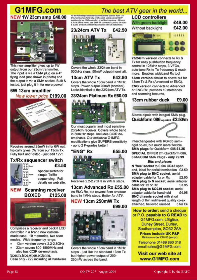
Page 48 CQ-TV 207 - August 2004 Copyright © by the BATC