cpx terminal - festo · extra−low voltage, pelv). take into account also the general requirements...
TRANSCRIPT
ElectronicsManual
CPX−I/O modules,− sub−bases,− pneumaticinterfaces and MPAelectronic modules
Types:
− CPX−...DE...− CPX−...DA− CPX−8DE−8DA
− CPX−AB−...
− VMPA−FB−EPL−...− CPX−GP−...− VABA−10S6−X1
− VMPA...−FB−EM..
CPX terminal
Manual526 440en 0705f [717440]

Contents and general instructions
IFesto P.BE−CPX−EA−EN en 0705f
Original German text. . . . . . . . . . . . . . . . . . . . . . . . . . . . . . .
Edition en 0705f. . . . . . . . . . . . . . . . . . . . . . . . . . . . . . . . . . .
Designation P.BE−CPX−EA−EN. . . . . . . . . . . . . . . . . . . . . . . . .
Order �no. 526 440. . . . . . . . . . . . . . . . . . . . . . . . . . . . . . . . .
E (Festo AG & Co. KG, D�73726 Esslingen, Federal Republic of Germany, 2007)Internet: �http://www.festo.comE−Mail: �[email protected]
The copying, distribution and utilization of this document as well as the communication of its contents to others without expressed authorization is prohibited. Violationsgive rise to compensation. All rights are reserved, in particu�lar the right to carry out patent, utility model or ornamentaldesign registration.
Contents and general instructions
II Festo P.BE−CPX−EA−EN en 0705f
CAGE CLAMP® is a registered trade mark of WAGO Kontakttechnik GmbH,32385 Minden, Germany
TORX® is a registered trade mark of CAMCAR TEXTRON INC., Rockford, Ill., USA
HARAX® is a registered trade mark of HARTING Deutschland GmbH,32381 Minden, Germany
SPEEDCON® is a registered trade mark of PHOENIX CONTACT GmbH & Co. KG, 32825 Blomberg, Germany
Contents and general instructions
IIIFesto P.BE−CPX−EA−EN en 0705f
Contents
Intended use VII . . . . . . . . . . . . . . . . . . . . . . . . . . . . . . . . . . . . . . . . . . . . . . . . . . . . . . . . . .
Target group VIII . . . . . . . . . . . . . . . . . . . . . . . . . . . . . . . . . . . . . . . . . . . . . . . . . . . . . . . . . .
Service VIII . . . . . . . . . . . . . . . . . . . . . . . . . . . . . . . . . . . . . . . . . . . . . . . . . . . . . . . . . . . . . . .
Important user instructions IX . . . . . . . . . . . . . . . . . . . . . . . . . . . . . . . . . . . . . . . . . . . . . .
Notes on the use of this manual XI . . . . . . . . . . . . . . . . . . . . . . . . . . . . . . . . . . . . . . . . . . .
Structure of a CPX terminal XII . . . . . . . . . . . . . . . . . . . . . . . . . . . . . . . . . . . . . . . . . . . . . .
CPX pneumatic interfaces and MPA pneumatic modules XIII . . . . . . . . . . . . . . . . . . . . . . .
CPX I/O modules XIII . . . . . . . . . . . . . . . . . . . . . . . . . . . . . . . . . . . . . . . . . . . . . . . . . . . . . . .
Diagnosis via the field bus XV . . . . . . . . . . . . . . . . . . . . . . . . . . . . . . . . . . . . . . . . . . . . . . .
1. Pneumatic interfaces 1−1 . . . . . . . . . . . . . . . . . . . . . . . . . . . . . . . . . . . . . . . . . . .
1.1 Function of the pneumatic interfaces 1−3 . . . . . . . . . . . . . . . . . . . . . . . . . . . . . . .
1.1.1 Display and connecting elements 1−5 . . . . . . . . . . . . . . . . . . . . . . . . . . .
1.2 Fitting 1−8 . . . . . . . . . . . . . . . . . . . . . . . . . . . . . . . . . . . . . . . . . . . . . . . . . . . . . . . .
1.3 Settings for configuring the pneumatics 1−9 . . . . . . . . . . . . . . . . . . . . . . . . . . . . .
1.4 Installation 1−14 . . . . . . . . . . . . . . . . . . . . . . . . . . . . . . . . . . . . . . . . . . . . . . . . . . . .
1.5 Instructions on commissioning 1−15 . . . . . . . . . . . . . . . . . . . . . . . . . . . . . . . . . . . .
1.6 Diagnosis 1−19 . . . . . . . . . . . . . . . . . . . . . . . . . . . . . . . . . . . . . . . . . . . . . . . . . . . . .
1.6.1 Fault messages of the pneumatic interfaces 1−20 . . . . . . . . . . . . . . . . . .
1.6.2 LED display 1−21 . . . . . . . . . . . . . . . . . . . . . . . . . . . . . . . . . . . . . . . . . . . .
1.6.3 Fault treatment and parametrizing 1−23 . . . . . . . . . . . . . . . . . . . . . . . . . .
2. MPA pneumatic modules 2−1 . . . . . . . . . . . . . . . . . . . . . . . . . . . . . . . . . . . . . . . .
2.1 Function of the MPA pneumatic modules 2−3 . . . . . . . . . . . . . . . . . . . . . . . . . . . .
2.1.1 Display and connecting elements 2−6 . . . . . . . . . . . . . . . . . . . . . . . . . . .
2.2 Fitting 2−7 . . . . . . . . . . . . . . . . . . . . . . . . . . . . . . . . . . . . . . . . . . . . . . . . . . . . . . . .
2.3 Installation 2−11 . . . . . . . . . . . . . . . . . . . . . . . . . . . . . . . . . . . . . . . . . . . . . . . . . . . .
2.4 Instructions on commissioning 2−16 . . . . . . . . . . . . . . . . . . . . . . . . . . . . . . . . . . . .
2.4.1 Parameters of the MPA pneumatic modules 2−16 . . . . . . . . . . . . . . . . . .
2.5 Diagnosis 2−18 . . . . . . . . . . . . . . . . . . . . . . . . . . . . . . . . . . . . . . . . . . . . . . . . . . . . .
2.5.1 Composition of the LED display on MPA1 2−19 . . . . . . . . . . . . . . . . . . . .
2.5.2 Composition of the LED display on MPA2 2−20 . . . . . . . . . . . . . . . . . . . .
Contents and general instructions
IV Festo P.BE−CPX−EA−EN en 0705f
2.5.3 LED messages for MPA electronic modules with standard diagnosis . . . 2−22
2.5.4 Fault treatment and parametrizing 2−24 . . . . . . . . . . . . . . . . . . . . . . . . . .
3. Overview and connecting technology I/O modules 3−1 . . . . . . . . . . . . . . . . . . .
3.1 Components of an I/O module 3−3 . . . . . . . . . . . . . . . . . . . . . . . . . . . . . . . . . . . .
3.2 Connections 3−4 . . . . . . . . . . . . . . . . . . . . . . . . . . . . . . . . . . . . . . . . . . . . . . . . . . .
3.2.1 Display and connecting elements 3−8 . . . . . . . . . . . . . . . . . . . . . . . . . . .
3.2.2 Combinations of I/O modules and sub−bases 3−10 . . . . . . . . . . . . . . . . .
3.2.3 Connecting the cables and plugs to the sub−bases 3−13 . . . . . . . . . . . . .
3.3 Mounting 3−23 . . . . . . . . . . . . . . . . . . . . . . . . . . . . . . . . . . . . . . . . . . . . . . . . . . . . . .
3.3.1 Fitting the sub−bases 3−24 . . . . . . . . . . . . . . . . . . . . . . . . . . . . . . . . . . . . .
3.3.2 Fitting the screening/shield plates 3−28 . . . . . . . . . . . . . . . . . . . . . . . . . .
4. Input modules 4−1 . . . . . . . . . . . . . . . . . . . . . . . . . . . . . . . . . . . . . . . . . . . . . . . . .
4.1 Function of the input modules 4−3 . . . . . . . . . . . . . . . . . . . . . . . . . . . . . . . . . . . . .
4.2 Mounting 4−4 . . . . . . . . . . . . . . . . . . . . . . . . . . . . . . . . . . . . . . . . . . . . . . . . . . . . . .
4.3 Installation 4−5 . . . . . . . . . . . . . . . . . . . . . . . . . . . . . . . . . . . . . . . . . . . . . . . . . . . .
4.3.1 Input module CPX−4DE 4−6 . . . . . . . . . . . . . . . . . . . . . . . . . . . . . . . . . . .
4.3.2 Input module CPX−8DE 4−11 . . . . . . . . . . . . . . . . . . . . . . . . . . . . . . . . . . .
4.3.3 Input module CPX−8DE−D with channel diagnosis 4−16 . . . . . . . . . . . . . .
4.3.4 Input module CPX−16DE 4−21 . . . . . . . . . . . . . . . . . . . . . . . . . . . . . . . . . .
4.3.5 Input module CPX−16DE−D 4−24 . . . . . . . . . . . . . . . . . . . . . . . . . . . . . . . .
4.3.6 Input module CPX−8NDE 4−26 . . . . . . . . . . . . . . . . . . . . . . . . . . . . . . . . . .
4.4 Instructions on commissioning 4−31 . . . . . . . . . . . . . . . . . . . . . . . . . . . . . . . . . . . .
4.4.1 Parameters of the input modules type CPX−4DE, −8DE, −8DE−D, −16DE and−8NDE 4−31 . . . . . . . . . . . . . . . . . . . . . . . . . . . . . . . . . . . . . . . . . . . . . . . . .
4.5 Diagnosis 4−35 . . . . . . . . . . . . . . . . . . . . . . . . . . . . . . . . . . . . . . . . . . . . . . . . . . . . .
4.5.1 Fault messages of the input modules 4−35 . . . . . . . . . . . . . . . . . . . . . . .
4.5.2 LED display 4−37 . . . . . . . . . . . . . . . . . . . . . . . . . . . . . . . . . . . . . . . . . . . .
4.5.3 Fault treatment and parametrizing 4−40 . . . . . . . . . . . . . . . . . . . . . . . . . .
5. Output modules 5−1 . . . . . . . . . . . . . . . . . . . . . . . . . . . . . . . . . . . . . . . . . . . . . . . .
5.1 Function of the output modules 5−3 . . . . . . . . . . . . . . . . . . . . . . . . . . . . . . . . . . .
Contents and general instructions
VFesto P.BE−CPX−EA−EN en 0705f
5.2 Mounting 5−3 . . . . . . . . . . . . . . . . . . . . . . . . . . . . . . . . . . . . . . . . . . . . . . . . . . . . . .
5.3 Installation 5−4 . . . . . . . . . . . . . . . . . . . . . . . . . . . . . . . . . . . . . . . . . . . . . . . . . . . .
5.3.1 Output module CPX−4DA 5−5 . . . . . . . . . . . . . . . . . . . . . . . . . . . . . . . . . .
5.3.2 Output module CPX−8DA 5−11 . . . . . . . . . . . . . . . . . . . . . . . . . . . . . . . . . .
5.3.3 High−current output module CPX−8DA−H 5−17 . . . . . . . . . . . . . . . . . . . . .
5.4 Instructions on commissioning 5−22 . . . . . . . . . . . . . . . . . . . . . . . . . . . . . . . . . . . .
5.4.1 Parameters of the output modules types CPX−4DA, CPX−8DA and CPX−8DA−H 5−22 . . . . . . . . . . . . . . . . . . . . . . . . . . . . . . . . .
5.5 Diagnosis 5−25 . . . . . . . . . . . . . . . . . . . . . . . . . . . . . . . . . . . . . . . . . . . . . . . . . . . . .
5.5.1 Error messages of the output modules 5−26 . . . . . . . . . . . . . . . . . . . . . .
5.5.2 LED display 5−28 . . . . . . . . . . . . . . . . . . . . . . . . . . . . . . . . . . . . . . . . . . . .
5.5.3 Fault treatment and parametrizing 5−30 . . . . . . . . . . . . . . . . . . . . . . . . . .
6. Multi I/O modules 6−1 . . . . . . . . . . . . . . . . . . . . . . . . . . . . . . . . . . . . . . . . . . . . . .
6.1 Function of the multi I/O modules 6−4 . . . . . . . . . . . . . . . . . . . . . . . . . . . . . . . . .
6.2 Fitting 6−4 . . . . . . . . . . . . . . . . . . . . . . . . . . . . . . . . . . . . . . . . . . . . . . . . . . . . . . . .
6.3 Installation 6−5 . . . . . . . . . . . . . . . . . . . . . . . . . . . . . . . . . . . . . . . . . . . . . . . . . . . .
6.3.1 Multi I/O module CPX−8DE−8DA 6−6 . . . . . . . . . . . . . . . . . . . . . . . . . . . .
6.4 Instructions on commissioning 6−10 . . . . . . . . . . . . . . . . . . . . . . . . . . . . . . . . . . . .
6.5 Diagnosis 6−16 . . . . . . . . . . . . . . . . . . . . . . . . . . . . . . . . . . . . . . . . . . . . . . . . . . . . .
6.5.1 Error messages of the multi I/O modules 6−16 . . . . . . . . . . . . . . . . . . . .
6.5.2 LED display 6−18 . . . . . . . . . . . . . . . . . . . . . . . . . . . . . . . . . . . . . . . . . . . .
6.5.3 Error treatment and parametrizing 6−20 . . . . . . . . . . . . . . . . . . . . . . . . . .
A. Technical appendix A−1 . . . . . . . . . . . . . . . . . . . . . . . . . . . . . . . . . . . . . . . . . . . . .
A.1 Technical specifications of the pneumatic interfaces A−3 . . . . . . . . . . . . . . . . . . .
A.2 Technical specifications of the MPA electronic modules A−5 . . . . . . . . . . . . . . . .
A.3 Technical specifications of the input modules A−7 . . . . . . . . . . . . . . . . . . . . . . . .
A.4 Technical specifications of the output modules A−10 . . . . . . . . . . . . . . . . . . . . . . .
A.5 Technical specifications of the multi I/O modules A−13 . . . . . . . . . . . . . . . . . . . . .
A.6 Technical specifications of the sub−bases A−15 . . . . . . . . . . . . . . . . . . . . . . . . . . . .
A.7 Technical specifications of the sub−bases in metal design A−16 . . . . . . . . . . . . . .
A.8 Internal structure of the CPX modules A−17 . . . . . . . . . . . . . . . . . . . . . . . . . . . . . .
A.9 Examples of circuitry A−22 . . . . . . . . . . . . . . . . . . . . . . . . . . . . . . . . . . . . . . . . . . . .
Contents and general instructions
VI Festo P.BE−CPX−EA−EN en 0705f
A.9.1 Circuitry examples of PNP inputs A−22 . . . . . . . . . . . . . . . . . . . . . . . . . . .
A.9.2 Circuitry examples of PNP outputs A−22 . . . . . . . . . . . . . . . . . . . . . . . . . .
A.9.3 Circuitry examples of NPN inputs A−23 . . . . . . . . . . . . . . . . . . . . . . . . . . .
A.9.4 Circuitry example with DUO cable A−24 . . . . . . . . . . . . . . . . . . . . . . . . . .
A.9.5 Circuitry example with DNCV A−25 . . . . . . . . . . . . . . . . . . . . . . . . . . . . . .
A.10 Accessories A−26 . . . . . . . . . . . . . . . . . . . . . . . . . . . . . . . . . . . . . . . . . . . . . . . . . . . .
B. Index B−1 . . . . . . . . . . . . . . . . . . . . . . . . . . . . . . . . . . . . . . . . . . . . . . . . . . . . . . . . .
Contents and general instructions
VIIFesto P.BE−CPX−EA−EN en 0705f
Intended use
The CPX pneumatic interfaces, MPA pneumatic modules andCPX I/O modules described in this manual have been de�signed exclusively for use in conjunction with CPX terminalsfrom Festo. The pneumatic interfaces and I/O modules areonly to be used as follows:
� as specified in industrial applications
� without any modifications by the userOnly the conversions or modifications described in thedocumentation supplied with product are permitted.
� In perfect technical condition.
If additional commercially−available components such as sensors and actuators are connected, the specified limits forpressures, temperatures, electrical data, torques, etc. mustnot be exceeded.Please observe the standards specified in the relevantchapters and comply with technical regulations, as well aswith national and local regulations.
Warning· In order to provide the electric power supply, use onlyPELV circuits as per IEC/DIN EN 60204−1 (ProtectiveExtra−Low Voltage, PELV).Take into account also the general requirements forPELV circuits as per IEC/DIN EN 60204−1.
· Use only power packs which guarantee reliable electri�cal isolation of the operating voltage as per IEC/DIN EN 60204−1.
By the use of PELV power units, protection against electricshock (protection against direct and indirect contact) is guar�anteed in accordance with IEC/DIN EN 60204−1 (electricalequipment of machines, general requirements).

Contents and general instructions
VIII Festo P.BE−CPX−EA−EN en 0705f
Target group
This manual is intended exclusively for technicians trained incontrol and automation technology, who have experience ininstalling, commissioning, programming and diagnosing pro�grammable logic controllers (PLC) and field bus systems.
Service
Please consult your local Festo Service if you have any techni�cal problems.
Contents and general instructions
IXFesto P.BE−CPX−EA−EN en 0705f
Important user instructions
Danger categories
This manual contains instructions on the possible dangerswhich can occur if the product is not used correctly. Theseinstructions are marked (Warning, Caution, etc), printed on a shaded background and marked additionally with a picto�gram. A distinction is made between the following dangerwarnings:
Warning... means that failure to observe this instruction may resultin serious personal injury or damage to property.
Caution... means that failure to observe this instruction may resultin personal injury or damage to property.
Note... means that failure to observe this instruction may resultin damage to property.
The following pictogram marks passages in the text whichdescribe activities with electrostatically sensitive compo�nents.
Electrostatically sensitive devices: Incorrect handling canresult in damage to components.

Contents and general instructions
X Festo P.BE−CPX−EA−EN en 0705f
Identifying special information
The following pictograms mark passages in the text whichcontain special information.
Pictograms
InformationRecommendations, tips and references to other sources ofinformation.
Accessories:Information on necessary or useful accessories for the Festoproduct.
Environment:Information on the environment−friendly use of Festo prod�ucts.
Text markings
· The bullet indicates activities which may be carried out inany order.
1. Figures denote activities which must be carried out in thenumerical order specified.
� Hyphens indicate general activities.
Contents and general instructions
XIFesto P.BE−CPX−EA−EN en 0705f
Notes on the use of this manual
This manual contains general basic information on themethod of operation, on fitting and installing CPX pneumaticinterfaces, MPA pneumatic modules and CPX I/O modules.
General basic information on the method of operation, onfitting, installing and commissioning CPX terminals can befound in the CPX system manual.
Special information on commissioning, parametrizing anddiagnosing a CPX terminal with the field bus node you areusing can be found in the appropriate manual for the fieldbus node.
Information on further CPX modules can be found in the manual for the relevant module. An overview is provided intable Tab.�0/4.
Conventions
The special parameters of the modules are described in theindividual chapters. These appear in English on the Handheldtype CPX−MMI−1.

Contents and general instructions
XII Festo P.BE−CPX−EA−EN en 0705f
Structure of a CPX terminal
CPX terminals consist of electric function modules, individualmodules and components. The diagram below shows anexample:
1 2 3 4
5
6
7
8
1 Field bus node
2 I/O modules
3 Pneumatic interface
4 Pneumatic modules (example MPA)
5 Manifold sub−base with additional powersupply
6 Manifold sub−base without supply
7 Manifold sub−base with system supply
8 End plate
Fig.�0/1: Example of CPX terminal
Contents and general instructions
XIIIFesto P.BE−CPX−EA−EN en 0705f
CPX pneumatic interfaces and MPA pneumatic modules
An overview of the CPX pneumatic interfaces can be found inTab.�1/1 and of the MPA pneumatic modules in Tab.�2/1.
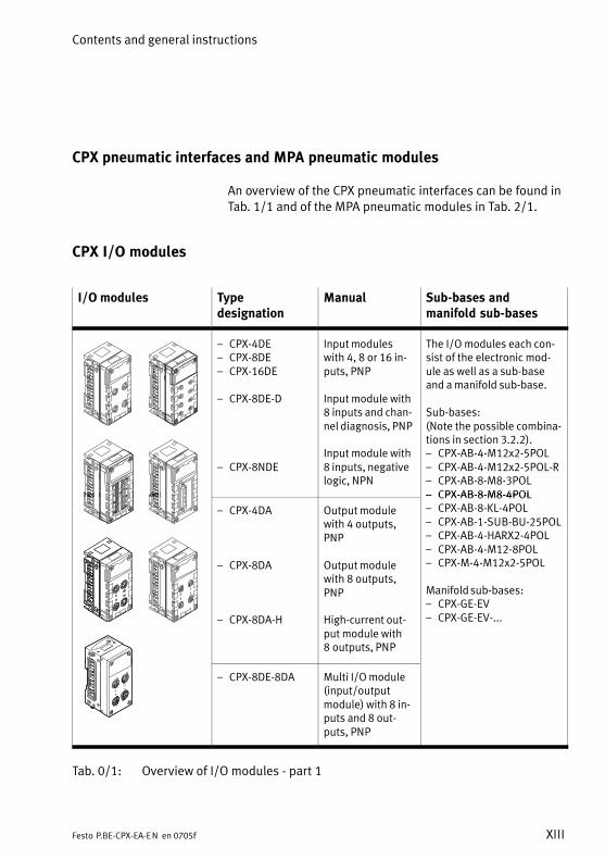
CPX I/O modules
I/O modules Type designation
Manual Sub−bases and manifold sub−bases
� CPX−4DE� CPX−8DE� CPX−16DE
� CPX−8DE−D
� CPX−8NDE
Input moduleswith 4, 8 or 16 in�puts, PNP
Input module with8 inputs and chan�nel diagnosis, PNP
Input module with8 inputs, negativelogic, NPN
The I/O modules each con�sist of the electronic mod�ule as well as a sub−baseand a manifold sub−base.
Sub−bases:(Note the possible combina�tions in section 3.2.2).� CPX−AB−4−M12x2−5POL� CPX−AB−4−M12x2−5POL−R� CPX−AB−8−M8−3POL� CPX−AB−8−M8−4POL
� CPX−4DA
� CPX−8DA
� CPX−8DA−H
Output modulewith 4 outputs,PNP
Output modulewith 8 outputs,PNP
High−current out�put module with8�outputs, PNP
� CPX−AB−8−M8−4POL� CPX−AB−8−KL−4POL� CPX−AB−1−SUB−BU−25POL� CPX−AB−4−HARX2−4POL� CPX−AB−4−M12−8POL� CPX−M−4−M12x2−5POL
Manifold sub−bases:� CPX−GE−EV� CPX−GE−EV−...
� CPX−8DE−8DA Multi I/O module(input/outputmodule) with 8 in�puts and 8 out�puts, PNP
Tab.�0/1: Overview of I/O modules − part�1
Contents and general instructions
XIV Festo P.BE−CPX−EA−EN en 0705f
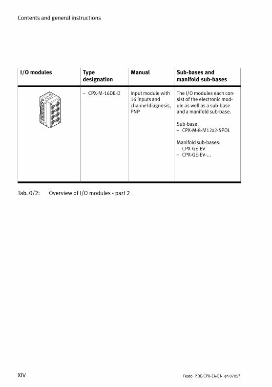
I/O modules Type designation
Manual Sub−bases and manifold sub−bases
� CPX−M−16DE−D Input module with16�inputs andchannel diagnosis,PNP
The I/O modules each con�sist of the electronic mod�ule as well as a sub−baseand a manifold sub−base.
Sub−base:� CPX−M−8−M12x2−5POL
Manifold sub−bases:� CPX−GE−EV� CPX−GE−EV−...
Tab.�0/2: Overview of I/O modules − part�2
Contents and general instructions
XVFesto P.BE−CPX−EA−EN en 0705f
Diagnosis via the field bus
Depending on the parametrization, CPX pneumatic interfacesand CPX I/O modules register specific faults via the field bus.
These can be evaluated via the:
� status bits (system status)
� I/O diagnostic interface (system diagnosis)
� module diagnosis
� fault numbers
Further information on diagnosis can be found in the CPXsystem manual or in the manual for the field bus node.
Contents and general instructions
XVI Festo P.BE−CPX−EA−EN en 0705f
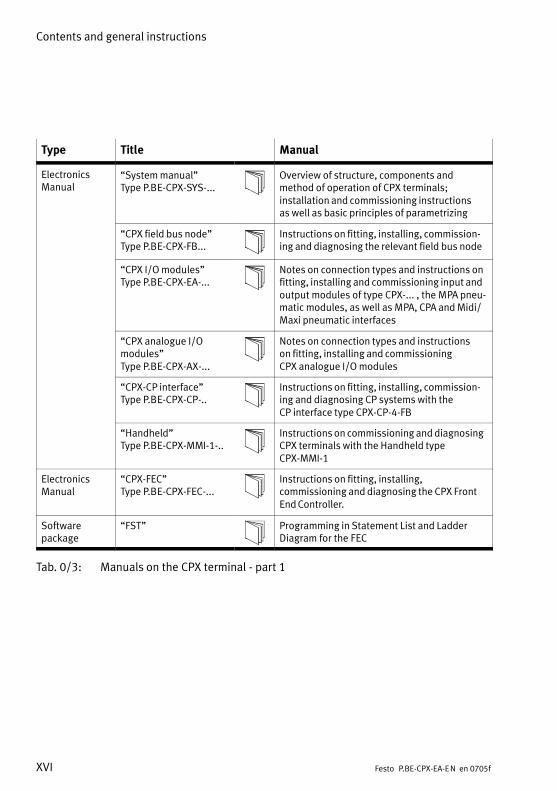
Type Title Manual
ElectronicsManual
�System manual" Type P.BE−CPX−SYS−...
Overview of structure, components andmethod of operation of CPX terminals;installation and commissioning instructions as well as basic principles of parametrizing
�CPX field bus node"Type P.BE−CPX−FB...
Instructions on fitting, installing, commission�ing and diagnosing the relevant field bus node
�CPX I/O modules"Type P.BE−CPX−EA−...
Notes on connection types and instructions onfitting, installing and commissioning input andoutput modules of type CPX−... , the MPA pneu�matic modules, as well as MPA, CPA and Midi/Maxi pneumatic interfaces
�CPX analogue I/O modules"Type P.BE−CPX−AX−...
Notes on connection types and instructions on fitting, installing and commissioning CPX analogue I/O modules
�CPX−CP interface"Type P.BE−CPX−CP−..
Instructions on fitting, installing, commission�ing and diagnosing CP systems with the CP interface type CPX−CP−4−FB
�Handheld"Type P.BE−CPX−MMI−1−..
Instructions on commissioning and diagnosingCPX terminals with the Handheld type�CPX−MMI−1
ElectronicsManual
�CPX−FEC"Type P.BE−CPX−FEC−...
Instructions on fitting, installing, commissioning and diagnosing the CPX FrontEnd Controller.
Software package
�FST" Programming in Statement List and LadderDiagram for the FEC
Tab.�0/3: Manuals on the CPX terminal − part 1
Contents and general instructions
XVIIFesto P.BE−CPX−EA−EN en 0705f
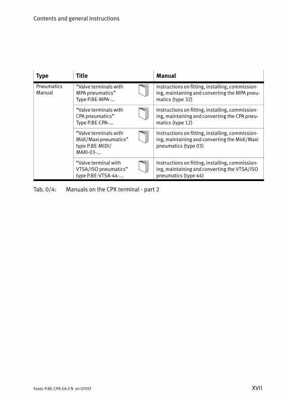
Type Title Manual
PneumaticsManual
�Valve terminals withMPA pneumatics"Type P.BE−MPA−...
Instructions on fitting, installing, commission�ing, maintaining and converting the MPA pneu�matics (type 32)
�Valve terminals withCPA pneumatics"Type P.BE−CPA−...
Instructions on fitting, installing, commission�ing, maintaining and converting the CPA pneu�matics (type 12)
�Valve terminals withMidi/Maxi pneumatics"type P.BE−MIDI/MAXI−03−...
Instructions on fitting, installing, commission�ing, maintaining and converting the Midi/Maxipneumatics (type 03)
�Valve terminal withVTSA/ISO pneumatics"type P.BE−VTSA−44−...
Instructions on fitting, installing, commission�ing, maintaining and converting the VTSA/ISOpneumatics (type 44)
Tab.�0/4: Manuals on the CPX terminal − part 2
Contents and general instructions
XVIII Festo P.BE−CPX−EA−EN en 0705f
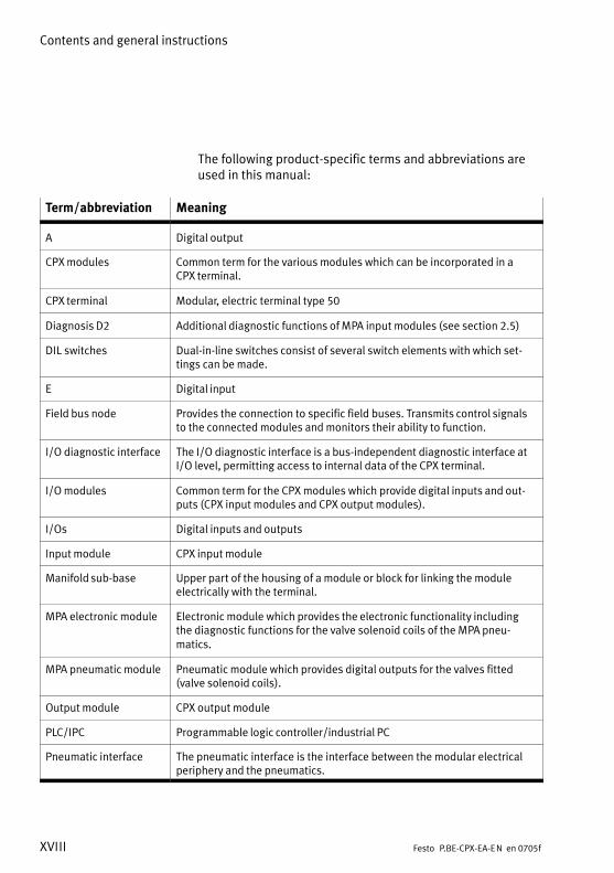
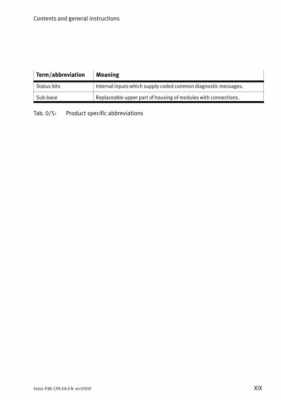
The following product−specific terms and abbreviations areused in this manual:
Term/abbreviation Meaning
A Digital output
CPX modules Common term for the various modules which can be incorporated in a CPX terminal.
CPX terminal Modular, electric terminal type 50
Diagnosis D2 Additional diagnostic functions of MPA input modules (see section 2.5)
DIL switches Dual−in−line switches consist of several switch elements with which set�tings can be made.
E Digital input
Field bus node Provides the connection to specific field buses. Transmits control signalsto the connected modules and monitors their ability to function.
I/O diagnostic interface The I/O diagnostic interface is a bus−independent diagnostic interface atI/O level, permitting access to internal data of the CPX terminal.
I/O modules Common term for the CPX modules which provide digital inputs and out�puts (CPX input modules and CPX output modules).
I/Os Digital inputs and outputs
Input module CPX input module
Manifold sub−base Upper part of the housing of a module or block for linking the moduleelectrically with the terminal.
MPA electronic module Electronic module which provides the electronic functionality includingthe diagnostic functions for the valve solenoid coils of the MPA pneu�matics.
MPA pneumatic module Pneumatic module which provides digital outputs for the valves fitted(valve solenoid coils).
Output module CPX output module
PLC/IPC Programmable logic controller/industrial PC
Pneumatic interface The pneumatic interface is the interface between the modular electricalperiphery and the pneumatics.
Contents and general instructions
XIXFesto P.BE−CPX−EA−EN en 0705f
Term/abbreviation Meaning
Status bits Internal inputs which supply coded common diagnostic messages.
Sub−base Replaceable upper part of housing of modules with connections.
Tab.�0/5: Product specific abbreviations
Contents and general instructions
XX Festo P.BE−CPX−EA−EN en 0705f
Pneumatic interfaces
1−1Festo P.BE−CPX−EA−EN en 0705f
Chapter 1
Type VMPA−FB−EPL−...CPX−GP−03−4.0CPX−GP−CPA−10CPX−GP−CPA−14VABA−10S6−X1
1. Pneumatic interfaces
1−2 Festo P.BE−CPX−EA−EN en 0705f
Contents
1. Pneumatic interfaces 1−1 . . . . . . . . . . . . . . . . . . . . . . . . . . . . . . . . . . . . . . . . . . .
1.1 Function of the pneumatic interfaces 1−3 . . . . . . . . . . . . . . . . . . . . . . . . . . . . . . .
1.1.1 Display and connecting elements 1−5 . . . . . . . . . . . . . . . . . . . . . . . . . . .
1.2 Fitting 1−8 . . . . . . . . . . . . . . . . . . . . . . . . . . . . . . . . . . . . . . . . . . . . . . . . . . . . . . . .
1.3 Settings for configuring the pneumatics 1−9 . . . . . . . . . . . . . . . . . . . . . . . . . . . . .
1.4 Installation 1−14 . . . . . . . . . . . . . . . . . . . . . . . . . . . . . . . . . . . . . . . . . . . . . . . . . . . .
1.5 Instructions on commissioning 1−15 . . . . . . . . . . . . . . . . . . . . . . . . . . . . . . . . . . . .
1.6 Diagnosis 1−19 . . . . . . . . . . . . . . . . . . . . . . . . . . . . . . . . . . . . . . . . . . . . . . . . . . . . .
1.6.1 Fault messages of the pneumatic interfaces 1−20 . . . . . . . . . . . . . . . . . .
1.6.2 LED display 1−21 . . . . . . . . . . . . . . . . . . . . . . . . . . . . . . . . . . . . . . . . . . . .
1.6.3 Fault treatment and parametrizing 1−23 . . . . . . . . . . . . . . . . . . . . . . . . . .

1. Pneumatic interfaces
1−3Festo P.BE−CPX−EA−EN en 0705f
1.1 Function of the pneumatic interfaces
The CPX pneumatic interfaces in a CPX valve terminal providethe connection to the pneumatic modules. The pneumatic modules enable pneumatic actuators to becontrolled by means of the valves fitted.
Pneumaticinterfaces
Type designation Description Connection toPneumatics
� VMPA−FB−EPL−... CPX pneumatic interfaceto MPA
Pneumatic interface forconnecting the modularelectrical peripherals oftype 50 (CPX) to valveterminals type 32 (MPA).
� VABA−10S6−X1 CPX pneumatic interfacefor VTSA pneumatics(ISO, type 44)
Pneumatic interface forconnecting the modularelectrical peripherals oftype 50 (CPX) to VTSA/ISOvalves (type�44)
� CPX−GP−03−4.0 CPX pneumatic interfaceto Midi/Maxi
Pneumatic interface forconnecting the modularelectrical periphery type�50(CPX) to valve terminalstype 03 (Midi/Maxi).
� CPX−GP−CPA−10
� CPX−GP−CPA−14
CPX pneumatic interfaceto CPA10
CPX pneumatic interfaceto CPA14
Pneumatic interface forconnecting the modularelectrical periphery type�50(CPX) to valve terminalstype 12 (CPA).
Tab.�1/1: Overview of pneumatic interfaces

1. Pneumatic interfaces
1−4 Festo P.BE−CPX−EA−EN en 0705f
MPA pneumatics From the technical point of view, the individual MPA pneu�matic modules each represent an electric module with e.g.8�digital outputs for controlling the valves fitted(see�chapter 2).
Please noteThe pneumatic interface for MPA pneumatics provides themechanical and electrical connection to the MPA pneu�matic modules.
As regards the CPX terminal, this pneumatic interface doesnot therefore count as an electric module.
Midi/Maxi pneumatics,CPA pneumatics or VTSApneumatics
From the technical point of view, the pneumatic interfacesfor Midi/Maxi pneumatics, CPA pneumatics or VTSA pneu�matics (ISO) each represent an electric module with a vari�able (configurable) number of digital outputs for controllingthe valves fitted (see following sections).
1. Pneumatic interfaces
1−5Festo P.BE−CPX−EA−EN en 0705f
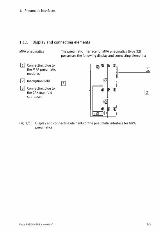
1.1.1 Display and connecting elements
MPA pneumatics The pneumatic interface for MPA pneumatics (type 32)possesses the following display and connecting elements:
1 Connecting plug tothe MPA pneumaticmodules
2 Inscription field
3 Connecting plug tothe CPX manifoldsub−bases
1
2
3
Fig.�1/1: Display and connecting elements of the pneumatic interface for MPApneumatics
1. Pneumatic interfaces
1−6 Festo P.BE−CPX−EA−EN en 0705f
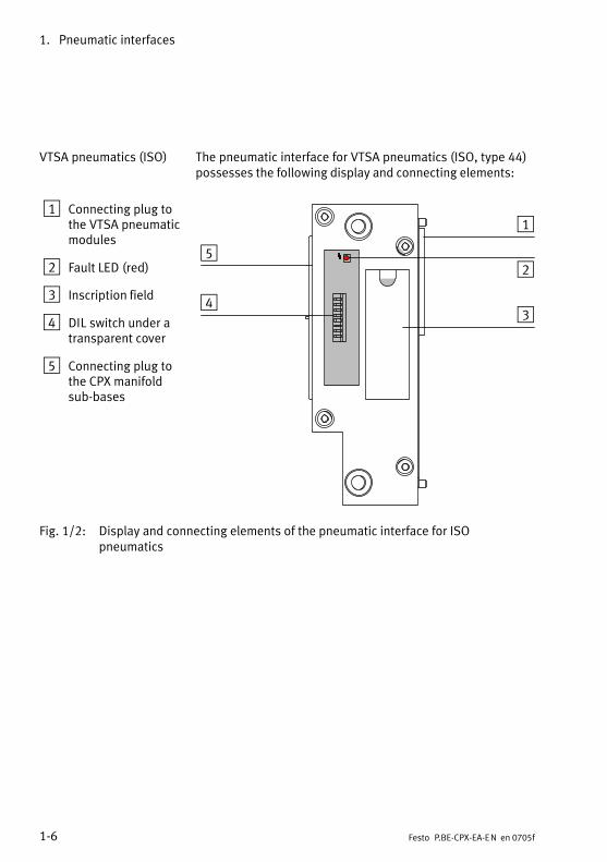
VTSA pneumatics (ISO) The pneumatic interface for VTSA pneumatics (ISO, type 44)possesses the following display and connecting elements:
1 Connecting plug tothe VTSA pneumaticmodules
2 Fault LED (red)
3 Inscription field
4 DIL switch under atransparent cover
5 Connecting plug tothe CPX manifoldsub−bases
1
2
34
5
Fig.�1/2: Display and connecting elements of the pneumatic interface for ISOpneumatics
1. Pneumatic interfaces
1−7Festo P.BE−CPX−EA−EN en 0705f
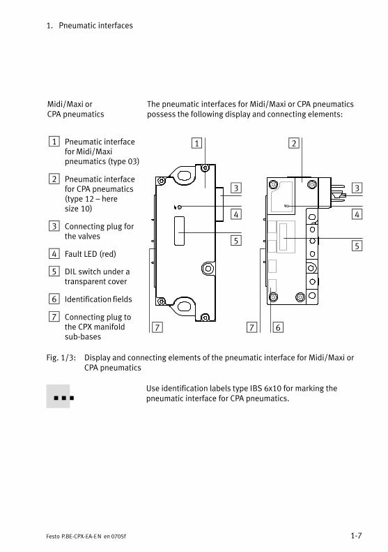
Midi/Maxi or CPA pneumatics
The pneumatic interfaces for Midi/Maxi or CPA pneumaticspossess the following display and connecting elements:
1 Pneumatic interfacefor Midi/Maxipneumatics (type�03)
2 Pneumatic interfacefor CPA pneumatics(type 12 � heresize�10)
3 Connecting plug forthe valves
4 Fault LED (red)
5 DIL switch under atransparent cover
6 Identification fields
7 Connecting plug tothe CPX manifoldsub−bases
1 2
3
4
5
6
3
4
5
7 7
Fig.�1/3: Display and connecting elements of the pneumatic interface for Midi/Maxi orCPA pneumatics
Use identification labels type IBS 6x10 for marking thepneumatic interface for CPA pneumatics.
1. Pneumatic interfaces
1−8 Festo P.BE−CPX−EA−EN en 0705f
1.2 Fitting
WarningSudden unexpected movement of the connected actuatorsand uncontrolled movements of loose tubing can causeinjury to human beings or damage to property.
Before carrying out installation and maintenance work,switch off the following:
� the compressed air supply
� the operating and load voltage supplies.
The CPX terminal must first be dismantled before it can beextended or converted, or when a pneumatic interface mustbe replaced. Instructions on this can be found in the CPXsystem manual.Instructions on extending or converting the pneumaticmodules can be found in the appropriate pneumatics manual.
For Midi/Maxi, CPA or ISO pneumatic interfaces:The setting of the DIL switches for configuring the pneumatics(valves used) can be set on the CPX terminal without the needto disamantle the terminal.
1. Pneumatic interfaces
1−9Festo P.BE−CPX−EA−EN en 0705f
1.3 Settings for configuring the pneumatics
Midi/Maxi, CPA or VTSA pneumatics
Settings for configuring the pneumatics are only necessarywith the pneumatic interfaces for Midi/Maxi, CPA and VTSApneumatics (ISO).
No settings are required for MPA pneumatics.
CautionAfter conversion or extension of the Midi/Maxi, CPA orVTSA pneumatics, the number of output addresses occu�pied by the pneumatics must be set on a DIL switch on thepneumatic interface.
CPX terminals can be fitted with various valves and electricmodules in accordance with the customer’s wishes.
The size of the valve address range on Midi/Max, CPA orVTSA pneumatics is not modified when the valves are ex�tended or converted, providing sufficient address space hasalready been reserved for the extension. The valve addressrange must be set with a DIL switch. The DIL switch is situ�ated under the transparent cover on the pneumatic interface.
WarningSudden unexpected movement of the connected actuatorsand uncontrolled movements of loose tubing can causeinjury to human beings or damage to property.
Before carrying out installation and maintenance work,switch off the following:
� the compressed air supply
� the operating and load voltage supplies.
1. Pneumatic interfaces
1−10 Festo P.BE−CPX−EA−EN en 0705f
CautionModules may be damaged if they are not handledcorrectly.
· Do not touch the electrical contacts of the modules.
· Observe the regulations for handling electrostaticallysensitive components.
· Discharge yourself electrostatically before fitting or re�moving components in order to protect the componentsagainst discharges of static electricity.
Please noteHandle all modules and components of the CPX terminalwith great care. Please note especially the following:
· Screws must be fitted accurately (otherwise threads willbe damaged). Screws must be fastened at first only by hand. Place thescrews so that the self−cutting threads are used.
· The specified torques must be observed.
· Screw connections must be fitted free of offset andmechanical tension.
· Check the seals for damage (IP65).
· Connecting surfaces must be clean (to ensure sealingeffect, avoid leakage and contact faults).
The screw connection between the cover and the lowerpart of the CPA pneumatic interface is designed for at least10 fitting/removal cycles.
Removing the cover
1. Loosen the screws in the cover with a TORX screwdriversize T10.
2. Lift the cover up carefully.

1. Pneumatic interfaces
1−11Festo P.BE−CPX−EA−EN en 0705f
3. Set the DIL switch elements in accordance with the follow�ing table. Use a suitable tool, e.g. a small screwdriver, forsetting the DIL switches.
1 Printed circuitboard
2 Fault LED
3 DIL switches forconfiguring thepneumatics
1
2
3
Fig.�1/4: DIL switches on the pneumatic interface (here for CPA pneumatics)
The DIL switch contains 8 switch elements. These switchelements are numbered from 1...8. The positions OPEN (CPA,VTSA/ISO) or ON (Midi/Maxi) are marked.
Rules for setting
� If the number of valve solenoid coils fitted is less than thenumber of output addresses set with the DIL switch, thesuperfluous addresses will be reserved for later exten�sions (if the maximum number of valves is fitted, outputaddresses will then remain unused).
� Modifications to the configuration will not becomeeffective until the operating voltage is switched on again.
� 8 further output addresses per switch element will beassigned for valves in the address range.
� The setting of the highest−value DIL switch in the ON(closed) position is decisive for the assigned addressrange.
1. Pneumatic interfaces
1−12 Festo P.BE−CPX−EA−EN en 0705f
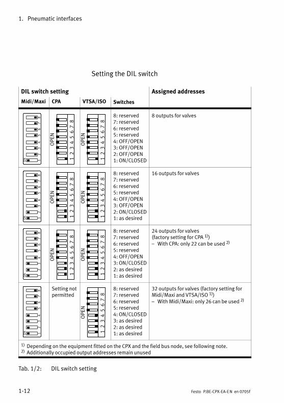
Setting the DIL switch
DIL switch setting Assigned addresses
Midi/Maxi CPA VTSA/ISO Switches
12
34
56
78
12345678
OPEN
12345678
OPEN
8: reserved7: reserved6: reserved5: reserved4: OFF/OPEN3: OFF/OPEN2: OFF/OPEN1: ON/CLOSED
8 outputs for valves
12
34
56
78
12345678
OPEN
12345678
OPEN
8: reserved7: reserved6: reserved5: reserved4: OFF/OPEN3: OFF/OPEN2: ON/CLOSED1: as desired
16 outputs for valves
12
34
56
78
12345678
OPEN
12345678
OPEN
8: reserved7: reserved6: reserved5: reserved4: OFF/OPEN3: ON/CLOSED2: as desired1: as desired
24 outputs for valves(factory setting for CPA 1)�)� With CPA: only 22 can be used 2)
12
34
56
78 Setting not
permitted
12345678
OPEN
8: reserved7: reserved6: reserved5: reserved4: ON/CLOSED3: as desired2: as desired1: as desired
32 outputs for valves (factory setting forMidi/Maxi and VTSA/ISO 1)�)� With Midi/Maxi: only 26 can be used 2)
1) Depending on the equipment fitted on the CPX and the field bus node, see following note.2) Additionally occupied output addresses remain unused
Tab.�1/2: DIL switch setting
1. Pneumatic interfaces
1−13Festo P.BE−CPX−EA−EN en 0705f
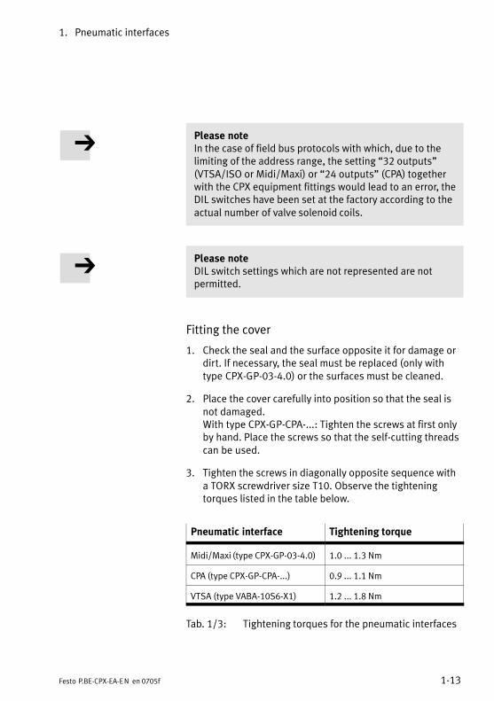
Please noteIn the case of field bus protocols with which, due to thelimiting of the address range, the setting �32 outputs"(VTSA/ISO or Midi/Maxi) or �24 outputs" (CPA) togetherwith the CPX equipment fittings would lead to an error, theDIL switches have been set at the factory according to theactual number of valve solenoid coils.
Please noteDIL switch settings which are not represented are notpermitted.
Fitting the cover
1. Check the seal and the surface opposite it for damage ordirt. If necessary, the seal must be replaced (only withtype CPX−GP−03−4.0) or the surfaces must be cleaned.
2. Place the cover carefully into position so that the seal isnot damaged.With type CPX−GP−CPA−...: Tighten the screws at first onlyby hand. Place the screws so that the self−cutting threadscan be used.
3. Tighten the screws in diagonally opposite sequence witha TORX screwdriver size T10. Observe the tighteningtorques listed in the table below.
Pneumatic interface Tightening torque
Midi/Maxi (type CPX−GP−03−4.0) 1.0 ... 1.3 Nm
CPA (type CPX−GP−CPA−...) 0.9 ... 1.1 Nm
VTSA (type VABA−10S6−X1) 1.2 ... 1.8 Nm
Tab.�1/3: Tightening torques for the pneumatic interfaces
1. Pneumatic interfaces
1−14 Festo P.BE−CPX−EA−EN en 0705f
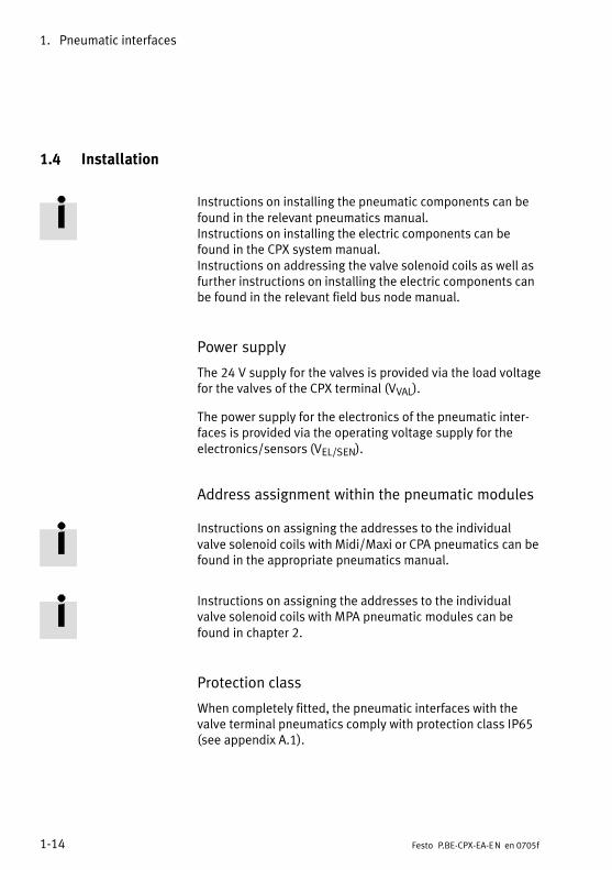
1.4 Installation
Instructions on installing the pneumatic components can befound in the relevant pneumatics manual. Instructions on installing the electric components can befound in the CPX system manual. Instructions on addressing the valve solenoid coils as well asfurther instructions on installing the electric components canbe found in the relevant field bus node manual.
Power supply
The 24 V supply for the valves is provided via the load voltagefor the valves of the CPX terminal (VVAL).
The power supply for the electronics of the pneumatic inter�faces is provided via the operating voltage supply for theelectronics/sensors (VEL/SEN).
Address assignment within the pneumatic modules
Instructions on assigning the addresses to the individualvalve solenoid coils with Midi/Maxi or CPA pneumatics can befound in the appropriate pneumatics manual.
Instructions on assigning the addresses to the individualvalve solenoid coils with MPA pneumatic modules can befound in chapter 2.
Protection class
When completely fitted, the pneumatic interfaces with thevalve terminal pneumatics comply with protection class IP65(see appendix A.1).
1. Pneumatic interfaces
1−15Festo P.BE−CPX−EA−EN en 0705f
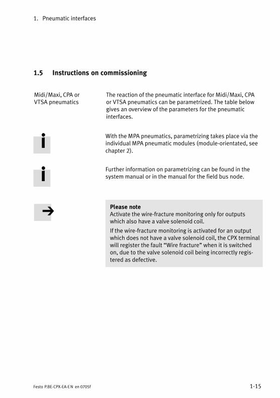
1.5 Instructions on commissioning
Midi/Maxi, CPA or VTSA pneumatics
The reaction of the pneumatic interface for Midi/Maxi, CPAor VTSA pneumatics can be parametrized. The table belowgives an overview of the parameters for the pneumaticinterfaces.
With the MPA pneumatics, parametrizing takes place via theindividual MPA pneumatic modules (module−orientated, seechapter 2).
Further information on parametrizing can be found in thesystem manual or in the manual for the field bus node.
Please noteActivate the wire−fracture monitoring only for outputswhich also have a valve solenoid coil.
If the wire−fracture monitoring is activated for an outputwhich does not have a valve solenoid coil, the CPX terminalwill register the fault �Wire fracture" when it is switchedon, due to the valve solenoid coil being incorrectly regis�tered as defective.

1. Pneumatic interfaces
1−16 Festo P.BE−CPX−EA−EN en 0705f
Parameters of pneumatic interfaces typesCPX−GP−03−4.0, CPX−GP−CPA−... and VABA−10S6−X1
Module parameters: Monitoring the CPX module
Function no. 4828 + m * 64 + 0 m = module number (0...47)
Description Monitoring of the possible faults can be activated or deactivated (suppressed)for each module separately. Active monitoring causes the following: The fault is:� sent to the CPX field bus node� displayed by the common module fault LED.
Bit23
MonitoringDescriptionUndervoltage of valves (VVAL)Short circuit at the valve (SCV)
[Monitor]
[Monitor Vval][Monitor SCV]
Values 1 = active0 = inactivePresetting: bit 2: active;
bit 3: inactive
[Active][Inactive]
Remark Monitoring can also be set for the complete CPX terminal (see CPX system manual).
[...] = display in the Handheld
Tab.�1/4: Monitoring the CPX module
1. Pneumatic interfaces
1−17Festo P.BE−CPX−EA−EN en 0705f
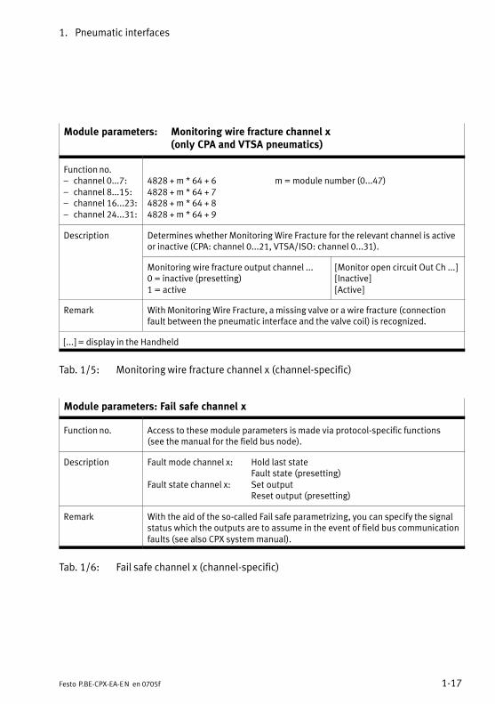
Module parameters: Monitoring wire fracture channel x (only CPA and VTSA pneumatics)
Function no.� channel 0...7:� channel 8...15:� channel 16...23:� channel 24...31:
4828 + m * 64 + 6 m = module number (0...47)4828 + m * 64 + 74828 + m * 64 + 84828 + m * 64 + 9
Description Determines whether Monitoring Wire Fracture for the relevant channel is activeor inactive (CPA: channel 0...21, VTSA/ISO: channel 0...31).
Monitoring wire fracture output channel ...0 = inactive (presetting)1 = active
[Monitor open circuit Out Ch ...][Inactive][Active]
Remark With Monitoring Wire Fracture, a missing valve or a wire fracture (connectionfault between the pneumatic interface and the valve coil) is recognized.
[...] = display in the Handheld
Tab.�1/5: Monitoring wire fracture channel x (channel−specific)
Module parameters: Fail safe channel x
Function no. Access to these module parameters is made via protocol−specific functions(see the manual for the field bus node).
Description Fault mode channel x: Hold last stateFault state (presetting)
Fault state channel x: Set outputReset output (presetting)
Remark With the aid of the so−called Fail safe parametrizing, you can specify the signalstatus which the outputs are to assume in the event of field bus communicationfaults (see also CPX system manual).
Tab.�1/6: Fail safe channel x (channel−specific)
1. Pneumatic interfaces
1−18 Festo P.BE−CPX−EA−EN en 0705f
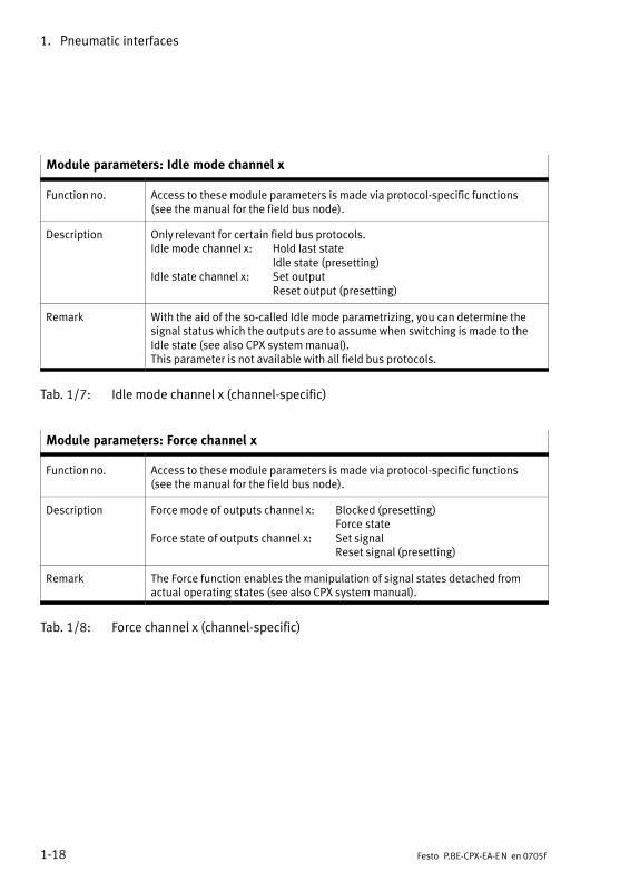
Module parameters: Idle mode channel x
Function no. Access to these module parameters is made via protocol−specific functions(see the manual for the field bus node).
Description Only relevant for certain field bus protocols.Idle mode channel x: Hold last state
Idle state (presetting)Idle state channel x: Set output
Reset output (presetting)
Remark With the aid of the so−called Idle mode parametrizing, you can determine thesignal status which the outputs are to assume when switching is made to theIdle state (see also CPX system manual).This parameter is not available with all field bus protocols.
Tab.�1/7: Idle mode channel x (channel−specific)
Module parameters: Force channel x
Function no. Access to these module parameters is made via protocol−specific functions(see the manual for the field bus node).
Description Force mode of outputs channel x: Blocked (presetting)Force state
Force state of outputs channel x: Set signalReset signal (presetting)
Remark The Force function enables the manipulation of signal states detached fromactual operating states (see also CPX system manual).
Tab.�1/8: Force channel x (channel−specific)
1. Pneumatic interfaces
1−19Festo P.BE−CPX−EA−EN en 0705f
1.6 Diagnosis
Midi/Maxi, CPA or VTSA pneumatics
Specific faults of the pneumatic interfaces are registered orsuppressed depending on the module parametrizing.
The faults are shown on−the−spot by means of the Fault LEDand, if necessary, can be evaluated with the Handheld (MMI).
Depending on the module parametrizing, the faults are sentto the field bus node, where they can be evaluated accordingto the field bus protocol used.
With the MPA pneumatics, parametrizing takes place via theindividual MPA pneumatic modules (module−orientated, seechapter 2).

1. Pneumatic interfaces
1−20 Festo P.BE−CPX−EA−EN en 0705f
1.6.1 Fault messages of the pneumatic interfaces
Midi/Maxi, CPA or VTSA pneumatics
A pneumatic interface can register the following standardfaults:
Fault number Description Fault treatment
5 Fault in load voltage for valvesLoad voltage for the valves (VVAL)missing or too low. 1)
· Check the load voltage
11 Fault short circuit at valve 2)
Short circuit/overload at the valve· Check that the valves are fitted
correctly and check the electricalconnections,
· If necessary, replace the valve
13 Fault wire fracture 2)
Monitoring the residual current of thevalve solenoid coils (open load, onlyactive with 0−signal).Only relevant for CPA or VTSA pneu�matics.
· Check that the valves are fittedcorrectly and check the electricalconnections,
· If necessary, replace the valve· Correct any faulty parametrizing (e.g.
with reserved valve locations/blank�ing plates, see section 1.3)
1) Tolerance range of the load voltage supply VVAL see �Technical specifications" in the appendix.2) Number of the faulty channel: see module diagnostic data.
Tab.�1/9: Fault messages of the pneumatic interface for Midi/Maxi, CPA or VTSApneumatics
1. Pneumatic interfaces
1−21Festo P.BE−CPX−EA−EN en 0705f
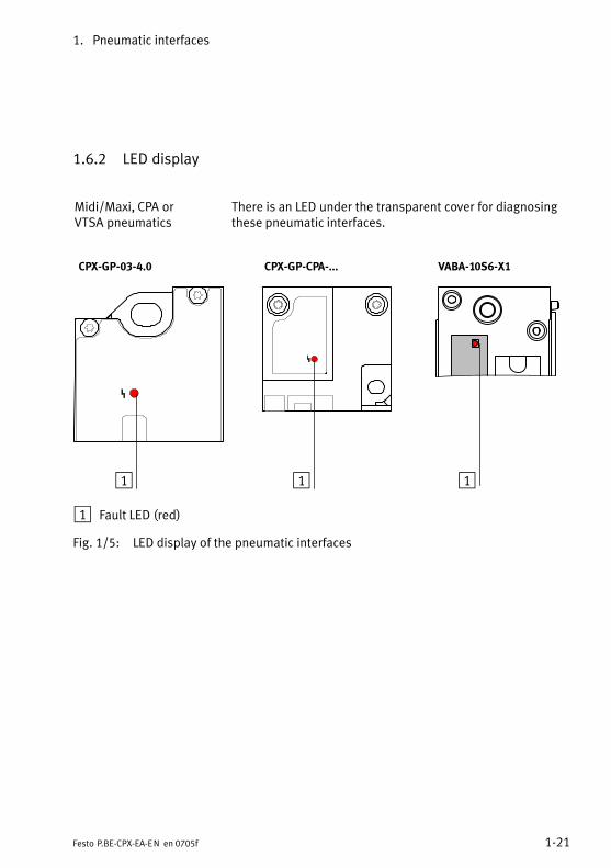
1.6.2 LED display
Midi/Maxi, CPA orVTSA pneumatics
There is an LED under the transparent cover for diagnosingthese pneumatic interfaces.
CPX−GP−03−4.0 CPX−GP−CPA−... VABA−10S6−X1
11 1
1 Fault LED (red)
Fig.�1/5: LED display of the pneumatic interfaces
1. Pneumatic interfaces
1−22 Festo P.BE−CPX−EA−EN en 0705f
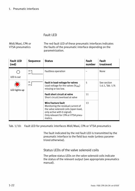
Fault LED
Midi/Maxi, CPA or VTSA pneumatics
The red fault LED of these pneumatic interfaces indicatesthe faults of the pneumatic interface depending on theparametrization.
Fault LED(red)
Sequence Status Faultnumber
Faulttreatment
LED is out
ON
OFF
Faultless operation � None
LED lights up
ON
OFFFault in load voltage for valvesLoad voltage for the valves (VVAL)missing or too low.
5 See section1.6.1, Tab.�1/9.
LED lights up
Fault short circuit at valveShort circuit/overload at valve
11
Wire fracture faultMonitoring the residual current ofthe valve solenoid coils (open load,only active with 0−signal).Only relevant for CPA or VTSA pneu�matics.
13
Tab.�1/10: Fault LED for pneumatic interfaces Midi/Maxi, CPA or VTSA pneumatics
The fault indicated by the red fault LED is transmitted by thepneumatic interface to the field bus node (unless parame�trized otherwise).
Status LEDs of the valve solenoid coils
The yellow status LEDs on the valve solenoid coils indicatethe status of the relevant output (see appropriate pneumaticsmanual).

1. Pneumatic interfaces
1−23Festo P.BE−CPX−EA−EN en 0705f
1.6.3 Fault treatment and parametrizing
Midi/Maxi, CPA or VTSA pneumatics
The following diagram shows the fault treatment of the pneu�matic interface for Midi/Maxi, CPA or VTSA pneumatics.Further registering and display of the faults can be sup�pressed as desired with the appropriate module parameters,represented in the diagram as switches. The parameters aredescribed in section 1.5.
2
Fault no. 5
Fault in loadvoltage forvalves
Fault message tofield bus node
...
Fault no. 11
Fault shortcircuit at valve,channel 0
Fault no. 13
Fault wirefracture,channel 0
Fault no. 11
Fault shortcircuit at valve,channel x
Fault no. 13
Fault wirefracture,channel x
MonitoringVVAL
MonitoringSCV
MonitoringWire fractureChannel 0
MonitoringWire fracturechannel x
Modulefault LED
3
1
...
...0 1 0 1 0 1 0 1
1 Module parameters (switch position represented = default setting)
2 Module−specific fault
3 Channel−specific faults (fault no. 13 only with CPA or VTSA pneumatics)
Fig.�1/6: Principle of fault treatment and parametrizing of the pneumatic interface forMidi/Maxi, CPA or VTSA pneumatics
1. Pneumatic interfaces
1−24 Festo P.BE−CPX−EA−EN en 0705f
MPA pneumatic modules
2−1Festo P.BE−CPX−EA−EN en 0705f
Chapter 2
Electronik modulesType VMPA1−FB−EMG−8
VMPA1−FB−EMS−8VMPA2−FB−EMG−4VMPA2−FB−EMS−4
2. MPA pneumatic modules
2−2 Festo P.BE−CPX−EA−EN en 0705f
Contents
2. MPA pneumatic modules 2−1 . . . . . . . . . . . . . . . . . . . . . . . . . . . . . . . . . . . . . . . .
2.1 Function of the MPA pneumatic modules 2−3 . . . . . . . . . . . . . . . . . . . . . . . . . . . .
2.1.1 Display and connecting elements 2−6 . . . . . . . . . . . . . . . . . . . . . . . . . . .
2.2 Fitting 2−7 . . . . . . . . . . . . . . . . . . . . . . . . . . . . . . . . . . . . . . . . . . . . . . . . . . . . . . . .
2.3 Installation 2−11 . . . . . . . . . . . . . . . . . . . . . . . . . . . . . . . . . . . . . . . . . . . . . . . . . . . .
2.4 Instructions on commissioning 2−16 . . . . . . . . . . . . . . . . . . . . . . . . . . . . . . . . . . . .
2.4.1 Parameters of the MPA pneumatic modules 2−16 . . . . . . . . . . . . . . . . . .
2.5 Diagnosis 2−18 . . . . . . . . . . . . . . . . . . . . . . . . . . . . . . . . . . . . . . . . . . . . . . . . . . . . .
2.5.1 Composition of the LED display on MPA1 2−19 . . . . . . . . . . . . . . . . . . . .
2.5.2 Composition of the LED display on MPA2 2−20 . . . . . . . . . . . . . . . . . . . .
2.5.3 LED messages for MPA electronic modules with standard diagnosis . . . 2−22
2.5.4 Fault treatment and parametrizing 2−24 . . . . . . . . . . . . . . . . . . . . . . . . . .
2. MPA pneumatic modules
2−3Festo P.BE−CPX−EA−EN en 0705f
2.1 Function of the MPA pneumatic modules
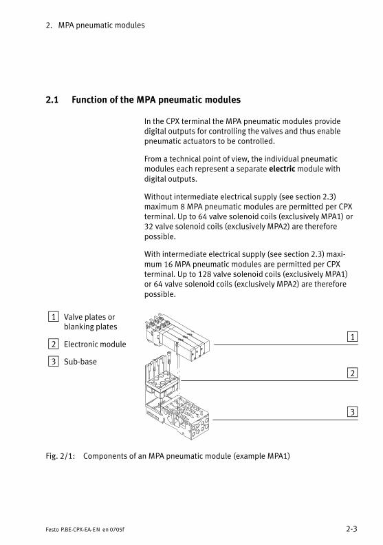
In the CPX terminal the MPA pneumatic modules providedigital outputs for controlling the valves and thus enablepneumatic actuators to be controlled.
From a technical point of view, the individual pneumaticmodules each represent a separate electric module withdigital outputs.
Without intermediate electrical supply (see section 2.3)maximum 8 MPA pneumatic modules are permitted per CPXterminal. Up to 64 valve solenoid coils (exclusively MPA1) or32�valve solenoid coils (exclusively MPA2) are thereforepossible.
With intermediate electrical supply (see section 2.3) maxi�mum 16 MPA pneumatic modules are permitted per CPXterminal. Up to 128 valve solenoid coils (exclusively MPA1)or 64�valve solenoid coils (exclusively MPA2) are thereforepossible.
1 Valve plates orblanking plates
2 Electronic module
3 Sub−base
1
2
3
Fig.�2/1: Components of an MPA pneumatic module (example MPA1)
2. MPA pneumatic modules
2−4 Festo P.BE−CPX−EA−EN en 0705f
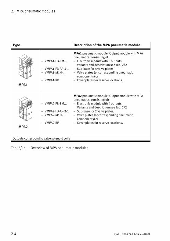
Type Description of the MPA pneumatic module
MPA1
� VMPA1−FB−EM...
� VMPA1−FB−AP−4−1� VMPA1−M1H−...
� VMPA1−RP
MPA1 pneumatic module: Output module with MPApneumatics, consisting of:� Electronic module with 8 outputs
Variants and description see Tab.�2/2� Sub−base for 4 valve plates� Valve plates (or corresponding pneumatic
components) or� Cover plates for reserve locations.
MPA2
� VMPA2−FB−EM...
� VMPA2−FB−AP−2−1� VMPA2−M1H−...
� VMPA2−RP
MPA2 pneumatic module: Output module with MPApneumatics, consisting of:� Electronic module with 4 outputs
Variants and description see Tab.�2/2� Sub−base for 2 valve plates,� Valve plates (or corresponding pneumatic
components) or� Cover plates for reserve locations.
Outputs correspond to valve solenoid coils
Tab.�2/1: Overview of MPA pneumatic modules

2. MPA pneumatic modules
2−5Festo P.BE−CPX−EA−EN en 0705f
The electrical function of an MPA pneumatic module is deter�mined by the electronic module used. The following tableprovides an overview of the MPA electronic modules:
Type Description of the electronic module
VMPA1−FB−EMG−8 8 outputswith electrical isolation
VMPA1−...
VMPA1−FB−EMS−8 8 outputswithout electrical isolation
VMPA2−FB−EMG−4 4 outputswith electrical isolation
VMPA2−...
VMPA2−FB−EMS−4 4 outputswithout electrical isolation
Outputs correspond to valve solenoid coils
Tab.�2/2: Overview of the MPA electronic modules
2. MPA pneumatic modules
2−6 Festo P.BE−CPX−EA−EN en 0705f
2.1.1 Display and connecting elements
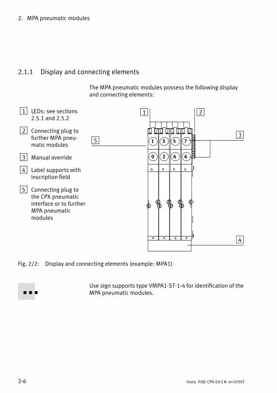
The MPA pneumatic modules possess the following displayand connecting elements:
1 LEDs: see sections2.5.1 and 2.5.2
2 Connecting plug tofurther MPA pneu�matic modules
3 Manual override
4 Label supports withinscription field
5 Connecting plug tothe CPX pneumaticinterface or to furtherMPA pneumaticmodules
1 2
3
4
5 1 3 5 7
0 2 4 6
Fig.�2/2: Display and connecting elements (example: MPA1)
Use sign supports type VMPA1−ST−1−4 for identification of theMPA pneumatic modules.
2. MPA pneumatic modules
2−7Festo P.BE−CPX−EA−EN en 0705f
2.2 Fitting
WarningSudden unexpected movement of the connected actuatorsand uncontrolled movements of loose tubing can causeinjury to human beings or damage to property.
Before carrying out installation and maintenance work,switch off the following:
� the compressed air supply
� the operating and load voltage supplies.
The CPX terminal must first be dismantled before it can beextended or converted, or when a pneumatic interface mustbe replaced. Instructions on this can be found in the CPX sys�tem manual.Instructions on extending or converting the MPA pneumaticmodules can be found in the appropriate pneumatics manual.
Electronic modules or valve plates can be replaced on thefitted CPX terminal.
CautionModules may be damaged if they are not handledcorrectly.
· Do not touch the electrical contacts of the modules.
· Observe the regulations for handling electrostaticallysensitive components.
· Discharge yourself electrostatically before fitting or re�moving components in order to protect the componentsagainst discharges of static electricity.
2. MPA pneumatic modules
2−8 Festo P.BE−CPX−EA−EN en 0705f
Please noteHandle all modules and components of the CPX terminalwith great care. Please note especially the following:
· Screws must be fitted accurately (otherwise threads willbe damaged).Screws must be fastened at first only by hand. Place thescrews so that the self−cutting threads are used.
· The specified torques must be observed.
· Screw connections must be fitted free of offset andmechanical tension.
· Check the seals for damage (IP65).
· Connecting surfaces must be clean (to ensure sealingeffect, avoid leakage and contact faults).
Dismantling the electronic module
1. Use a screwdriver with a narrow blade to loosen thefastening screws of all valve or blanking plates andremove the plates from the sub−bases.
2. Loosen the screws with which the electronic module isfastened to the sub−base.
3. Pull the electronic module upwards out of the body of thesub−base.
2. MPA pneumatic modules
2−9Festo P.BE−CPX−EA−EN en 0705f
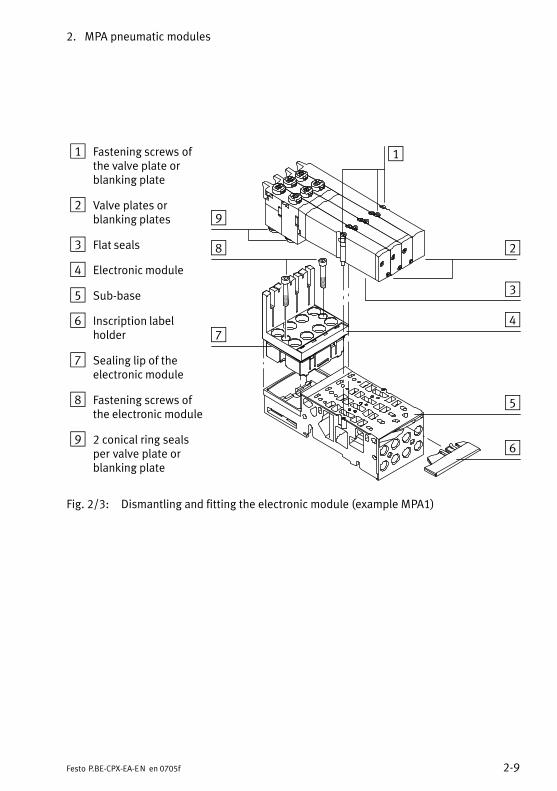
1 Fastening screws ofthe valve plate orblanking plate
2 Valve plates orblanking plates
3 Flat seals
4 Electronic module
5 Sub−base
6 Inscription labelholder
7 Sealing lip of theelectronic module
8 Fastening screws ofthe electronic module
9 2 conical ring sealsper valve plate orblanking plate
1
2
3
4
5
6
9
8
7
Fig.�2/3: Dismantling and fitting the electronic module (example MPA1)
2. MPA pneumatic modules
2−10 Festo P.BE−CPX−EA−EN en 0705f
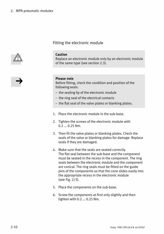
Fitting the electronic module
CautionReplace an electronic module only by an electronic moduleof the same type (see section 2.3).
Please noteBefore fitting, check the condition and position of thefollowing seals:
� the sealing lip of the electronic module
� the ring seal of the electrical contacts
� the flat seal of the valve plates or blanking plates.
1. Place the electronic module in the sub−base.
2. Tighten the screws of the electronic module with0.2�...�0.25�Nm.
3. Then fit the valve plates or blanking plates. Check theseals of the valve or blanking plates for damage. Replaceseals if they are damaged.
4. Make sure that the seals are seated correctly. The flat seal between the sub−base and the componentmust be seated in the recess in the component. The ringseals between the electronic module and the componentare conical. The ring seals must be fitted on the guidepins of the components so that the cone slides easily intothe appropriate recess in the electronic module(see�Fig.�2/3).
5. Place the components on the sub−base.
6. Screw the components at first only slightly and thentighten with 0.2 ... 0.25 Nm.

2. MPA pneumatic modules
2−11Festo P.BE−CPX−EA−EN en 0705f
2.3 Installation
Instructions on installing the pneumatic components can befound in the Pneumatics Manual type P.BE−MPA−...Instructions on installing the electric components can befound in the CPX System Manual. Instructions on addressing the valve solenoid coils as well asfurther instructions on installing the electric components canbe found in the relevant field bus node manual.
Power supply
The 24 V supply for the valves is provided via the load voltagefor the valves of the CPX terminal (VVAL).
The power supply for the electronic modules is provided viathe operating voltage supply for the electronics/sensors(VEL/SEN).
CautionDamage to components and functional damage!
It is not permitted to supply voltage to MPA pneumaticmodules with electronic modules without electrical isola�tion via a manifold sub−base type CPX−GE−EV−V... (valvesupply) or CPX−GE−EV−S−7/8−5POL (5−pin system supply).
· If your MPA pneumatics are fitted with electronic mod�ules of type VMPA1−FB−EMS−... or VMPA2−FB−EMS−...�,you must supply the MPA pneumatics exclusively via a4−pin system supply module type CPX−GE−EV−S or CPX−GE−EV−S−7/8−4POL.
Note the overview in Tab.�2/3.

2. MPA pneumatic modules
2−12 Festo P.BE−CPX−EA−EN en 0705f
Note that MPA electronic modules may only be supplied withpower via the following supply modules:
MPA electronicmodule
Permitted supply modules (type)
� VMPA1−FB−EMS−...� VMPA2−FB−EMS−...(in each case withoutelectrical isolation)
� System supply module CPX−GE−EV−S (M18 4−pin) or
� System supply module CPX−GE−EV−S−7/8−4POL (7/8" 4−pin)
� VMPA1−FB−EMG−...� VMPA2−FB−EMG−...(in each case withelectrical isolation)
� Valve supply modules CPX−GE−EV−V... (M18 or 7/8") or
� System supply modules CPX−GE−EV−S... (M18 or 7/8") 1)
� Intermediate electrical ssupply module(supply plate (electric) typeVMPA−FB−SP−...−V−...)
1) If a 4−pin system supply module is used, the electrical isolationwill no longer be effective.
Tab.�2/3: Permitted supply modules modules for MPAelectronic modules
In the case of MPA electronic modules with electrical isolationtype VMPA1−FB−EMG−... or VMPA2−FB−EMG−...�, VEL/SEN andVVAL are completely electrically isolated. In conjunction withthe following voltage supply modules, it is therefore possibleto switch off the valve supply voltage at all poles:
� Manifold sub−base with valve supply type CPX−GE−EV−V...(M18 or 7/8")
� 7/8" manifold sub−base with 5−pin system supply moduletype CPX−GE−EV−S−7/8−5POL
� Intermediate electrical supply module (supply plate(electric) type VMPA−FB−SP−...−V−...)
2. MPA pneumatic modules
2−13Festo P.BE−CPX−EA−EN en 0705f
24�V 0�V FE�24�V
0�Vval
FE�
0�V FE�24�Vn.c.
0�Vout
24�Vout
0�Vel/sen
24�Vel/sen
24�Vval
0�Vval
24�Vval
1 2 3 4 5
8
9
7
(Pin assignments see CPX System Manual)
6
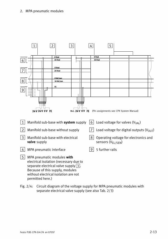
1 Manifold sub−base with system supply
2 Manifold sub−base without supply
3 Manifold sub−base with electricalvalve�supply
4 MPA pneumatic interface
5 MPA pneumatic modules withelectrical isolation (necessary due toseparate electrical valve supply 3.Because of this supply, moduleswithout electrical isolation are notpermitted here.)
6 Load voltage for valves (VVAL)
7 Load voltage for digital outputs (VOUT)
8 Operating voltage for electronics andsensors (VEL/SEN)
9 5 further rails
Fig.�2/4: Circuit diagram of the voltage supply for MPA pneumatic modules withseparate electrical valve supply (see also Tab.�2/3)

2. MPA pneumatic modules
2−14 Festo P.BE−CPX−EA−EN en 0705f
1 2 3 4 5 6
8
9
aJ
7
(Pin assignments see CPX System Manual)24�V 0�V FE�24�V
0�Vval
FE�
0�V FE�24�Vn.c.
0�Vout
24�Vout
0�Vel/sen
24�Vel/sen
24�Vval
0�Vval
24�Vval
1 Manifold sub−base with system supply
2 Manifold sub−base without supply
3 MPA pneumatic interface
4 MPA pneumatic module withoutelectrical isolation. Not permitted if the load supply VVALis provided via a sub−base withelectrical valve supply or 5−pin systemsupply (7/8").
5 Intermediate electrical supply module(type VMPA−FB−SP−...−V−...)
6 MPA pneumatic module with electricalisolation (necessary due to intermedi�ate electrical supply 5��)
7 Load voltage for valves (VVAL)
8 Load voltage for digital outputs (VOUT)
9 Operating voltage for electronics andsensors (VEL/SEN)
aJ 5 further rails
Fig.�2/5: Circuit diagram of the voltage supply for MPA pneumatic modules withintermediate electrical supply on the pneumatic side (see also Tab.�2/3)
Protection class
When completely fitted, the MPA pneumatic modules complywith protection class IP65 (see appendix A.1).
2. MPA pneumatic modules
2−15Festo P.BE−CPX−EA−EN en 0705f
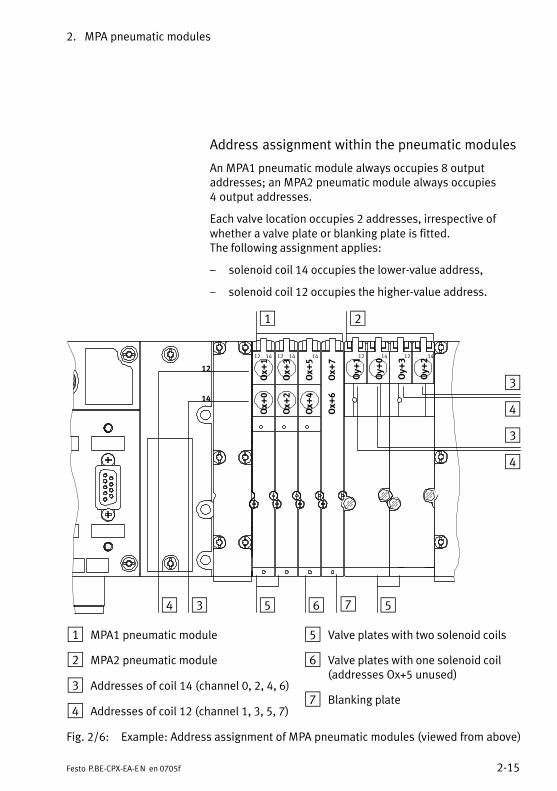
Address assignment within the pneumatic modules
An MPA1 pneumatic module always occupies 8 outputaddresses; an MPA2 pneumatic module always occupies4�output addresses.
Each valve location occupies 2 addresses, irrespective ofwhether a valve plate or blanking plate is fitted. The following assignment applies:
� solenoid coil 14 occupies the lower−value address,
� solenoid coil 12 occupies the higher−value address.
1 2
534 76
Ox+
2
Ox+
4
Ox+
6
Ox+
1
Ox+
3
Ox+
5
Ox+
7
Oy+
1
Oy+
0
Oy+
3
Oy+
2
12 14 12 14 14 12 14 12 14
Ox+
0
12
14
5
3
4
3
4
1 MPA1 pneumatic module
2 MPA2 pneumatic module
3 Addresses of coil 14 (channel 0, 2, 4, 6)
4 Addresses of coil 12 (channel 1, 3, 5, 7)
5 Valve plates with two solenoid coils
6 Valve plates with one solenoid coil(addresses Ox+5 unused)
7 Blanking plate
Fig.�2/6: Example: Address assignment of MPA pneumatic modules (viewed from above)

2. MPA pneumatic modules
2−16 Festo P.BE−CPX−EA−EN en 0705f
2.4 Instructions on commissioning
The reaction of the MPA pneumatic modules can be parame�trized. The tables below give an overview of the parametersfor the MPA pneumatic modules.
Further information on parametrizing can be found in thesystem manual or in the manual for the field bus node.
2.4.1 Parameters of the MPA pneumatic modules
The following parameters apply in general to all electronicmodules of the MPA pneumatic modules.
Module parameters: Monitoring the CPX module
Function no. 4828 + m * 64 + 0 m = module number (0...47)
Description Monitoring of the possible faults can be activated or deactivated (suppressed) foreach module separately. Active monitoring causes the following: The fault is:� displayed via the fault LEDs.� sent to the CPX field bus node
Bit2
MonitoringDescriptionUndervoltage of valves (VVAL)
[Parameters]
[Monitor Vout/val]
Values 1 = active (presetting)0 = inactive
[Active][Inactive]
Remark Monitoring can also be set for the complete CPX terminal (see CPX system manual).
Tab.�2/4: Monitoring the CPX module
2. MPA pneumatic modules
2−17Festo P.BE−CPX−EA−EN en 0705f
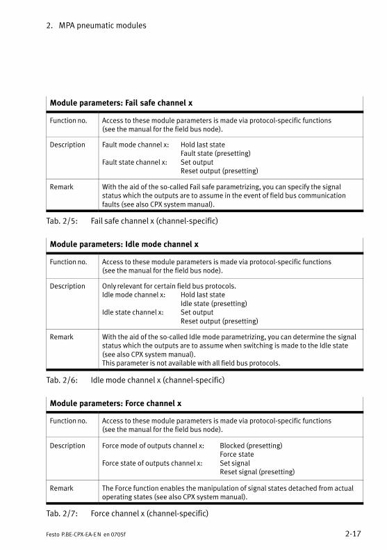
Module parameters: Fail safe channel x
Function no. Access to these module parameters is made via protocol−specific functions (see the manual for the field bus node).
Description Fault mode channel x: Hold last stateFault state (presetting)
Fault state channel x: Set outputReset output (presetting)
Remark With the aid of the so−called Fail safe parametrizing, you can specify the signalstatus which the outputs are to assume in the event of field bus communicationfaults (see also CPX system manual).
Tab.�2/5: Fail safe channel x (channel−specific)
Module parameters: Idle mode channel x
Function no. Access to these module parameters is made via protocol−specific functions (see the manual for the field bus node).
Description Only relevant for certain field bus protocols.Idle mode channel x: Hold last state
Idle state (presetting)Idle state channel x: Set output
Reset output (presetting)
Remark With the aid of the so−called Idle mode parametrizing, you can determine the signalstatus which the outputs are to assume when switching is made to the Idle state(see also CPX system manual).This parameter is not available with all field bus protocols.
Tab.�2/6: Idle mode channel x (channel−specific)
Module parameters: Force channel x
Function no. Access to these module parameters is made via protocol−specific functions (see the manual for the field bus node).
Description Force mode of outputs channel x: Blocked (presetting)Force state
Force state of outputs channel x: Set signalReset signal (presetting)
Remark The Force function enables the manipulation of signal states detached from actualoperating states (see also CPX system manual).
Tab.�2/7: Force channel x (channel−specific)
2. MPA pneumatic modules
2−18 Festo P.BE−CPX−EA−EN en 0705f
2.5 Diagnosis
Specific faults of the MPA pneumatic modules are registeredor suppressed depending on the module parametrizing.
The faults are shown on−the−spot via the fault LEDs and, ifnecessary, can be evaluated with the handheld.
VMPA1−...�, VMPA2−... MPA pneumatic modules with electronic modules of typesVMPA1−...−8 and VMPA2−...−4 can register the following stan�dard faults:
� Fault: Load voltage for valves (VVAL)
2. MPA pneumatic modules
2−19Festo P.BE−CPX−EA−EN en 0705f
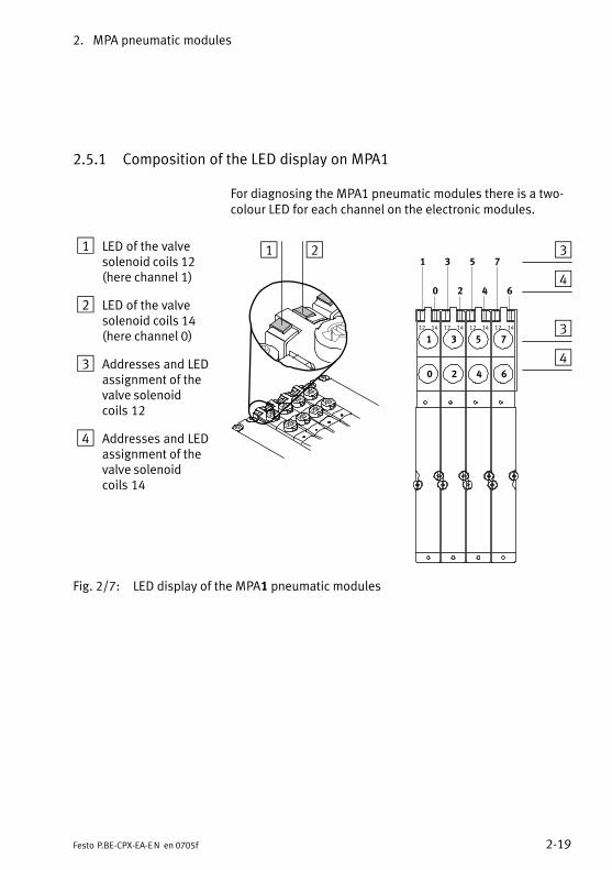
2.5.1 Composition of the LED display on MPA1
For diagnosing the MPA1 pneumatic modules there is a two−colour LED for each channel on the electronic modules.
1 LED of the valvesolenoid coils 12(here channel 1)
2 LED of the valvesolenoid coils 14 (here channel 0)
3 Addresses and LEDassignment of thevalve solenoidcoils�12
4 Addresses and LEDassignment of thevalve solenoidcoils�14
1 2 3
1 3 5 7
0 2 4 6
1 3 5 7
0 2 4 64
12 14 12 14 12 14 12 14 3
4
Fig.�2/7: LED display of the MPA1 pneumatic modules

2. MPA pneumatic modules
2−20 Festo P.BE−CPX−EA−EN en 0705f
2.5.2 Composition of the LED display on MPA2
For diagnosing the MPA2 pneumatic modules up to softwarestatus SW31.03.06, there is a two−colour LED for each chan�nel on the electronic modules:
1 LED of the valvesolenoid coils 12(here channel 1)
2 LED of the valvesolenoid coils 14(here channel 0)
3 Addresses and LEDassignment of thevalve solenoidcoils�12
4 Addresses and LEDassignment of thevalve solenoidcoils�14
1 2 31 3
0 24
3
4
1 0 3 212 14 12 14
3
4
Fig.�2/8: LED display of the MPA2 pneumatic modules up to software status SW31.03.06Rev. 4 (type ...−EMS−4) or SW31.03.06 Rev. 3 (type ...−EMG−4)
2. MPA pneumatic modules
2−21Festo P.BE−CPX−EA−EN en 0705f
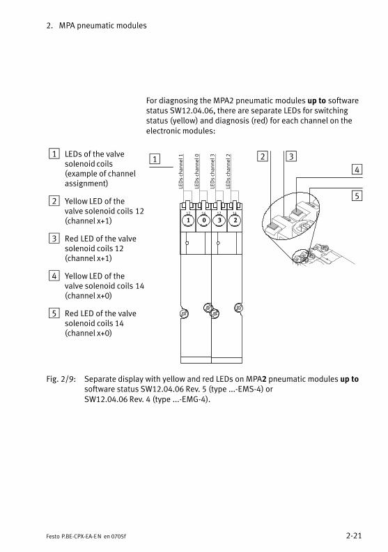
For diagnosing the MPA2 pneumatic modules up to softwarestatus SW12.04.06, there are separate LEDs for switchingstatus (yellow) and diagnosis (red) for each channel on theelectronic modules:
1 LEDs of the valvesolenoid coils(example of channelassignment)
2 Yellow LED of thevalve solenoid coils�12(channel x+1)
3 Red LED of the valvesolenoid coils 12(channel x+1)
4 Yellow LED of thevalve solenoid coils�14(channel x+0)
5 Red LED of the valvesolenoid coils 14(channel x+0)
1 2
1 0 3 212 14 12 14
34
LEDs channel 1
LEDs channel 0
LEDs channel 3
LEDs channel 2
5
Fig.�2/9: Separate display with yellow and red LEDs on MPA2 pneumatic modules up tosoftware status SW12.04.06 Rev. 5 (type ...−EMS−4) orSW12.04.06 Rev. 4 (type ...−EMG−4).
2. MPA pneumatic modules
2−22 Festo P.BE−CPX−EA−EN en 0705f
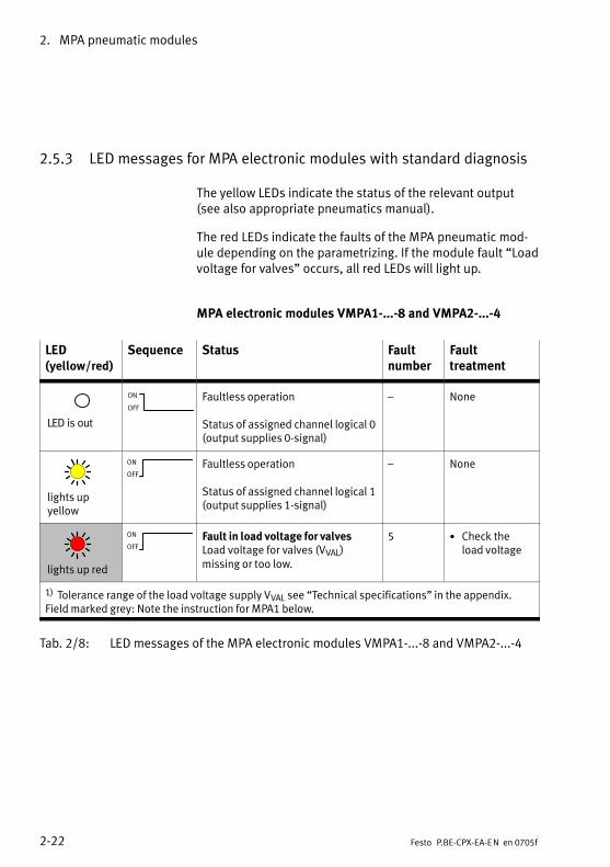
2.5.3 LED messages for MPA electronic modules with standard diagnosis
The yellow LEDs indicate the status of the relevant output(see also appropriate pneumatics manual).
The red LEDs indicate the faults of the MPA pneumatic mod�ule depending on the parametrizing. If the module fault �Loadvoltage for valves" occurs, all red LEDs will light up.
MPA electronic modules VMPA1−...−8 and VMPA2−...−4
LED (yellow/red)
Sequence Status Faultnumber
Faulttreatment
LED is out
ON
OFF
Faultless operation
Status of assigned channel logical 0(output supplies 0−signal)
� None
lights upyellow
ON
OFF
Faultless operation
Status of assigned channel logical 1(output supplies 1−signal)
� None
lights up red
ON
OFF
Fault in load voltage for valvesLoad voltage for valves (VVAL)missing or too low.
5 · Check theload voltage
1) Tolerance range of the load voltage supply VVAL see �Technical specifications" in the appendix.Field marked grey: Note the instruction for MPA1 below.
Tab.�2/8: LED messages of the MPA electronic modules VMPA1−...−8 and VMPA2−...−4
2. MPA pneumatic modules
2−23Festo P.BE−CPX−EA−EN en 0705f
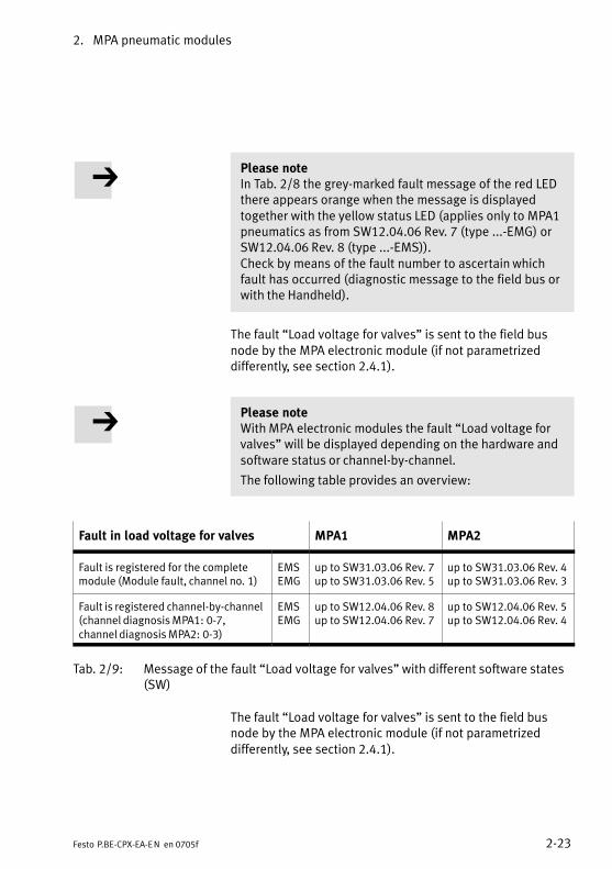
Please noteIn Tab.�2/8 the grey−marked fault message of the red LEDthere appears orange when the message is displayedtogether with the yellow status LED (applies only to MPA1pneumatics as from SW12.04.06 Rev. 7 (type ...−EMG) orSW12.04.06 Rev. 8 (type ...−EMS)).Check by means of the fault number to ascertain whichfault has occurred (diagnostic message to the field bus orwith the Handheld).
The fault �Load voltage for valves" is sent to the field busnode by the MPA electronic module (if not parametrizeddifferently, see section 2.4.1).
Please noteWith MPA electronic modules the fault �Load voltage forvalves" will be displayed depending on the hardware andsoftware status or channel−by−channel.
The following table provides an overview:
Fault in load voltage for valves MPA1 MPA2
Fault is registered for the completemodule (Module fault, channel no. 1)
EMSEMG
up to SW31.03.06 Rev. 7up to SW31.03.06 Rev. 5
up to SW31.03.06 Rev. 4up to SW31.03.06 Rev. 3
Fault is registered channel−by−channel(channel diagnosis MPA1: 0−7,channel diagnosis MPA2: 0−3)
EMSEMG
up to SW12.04.06 Rev. 8up to SW12.04.06 Rev. 7
up to SW12.04.06 Rev. 5up to SW12.04.06 Rev. 4
Tab.�2/9: Message of the fault �Load voltage for valves" with different software states(SW)
The fault �Load voltage for valves" is sent to the field busnode by the MPA electronic module (if not parametrizeddifferently, see section 2.4.1).
2. MPA pneumatic modules
2−24 Festo P.BE−CPX−EA−EN en 0705f
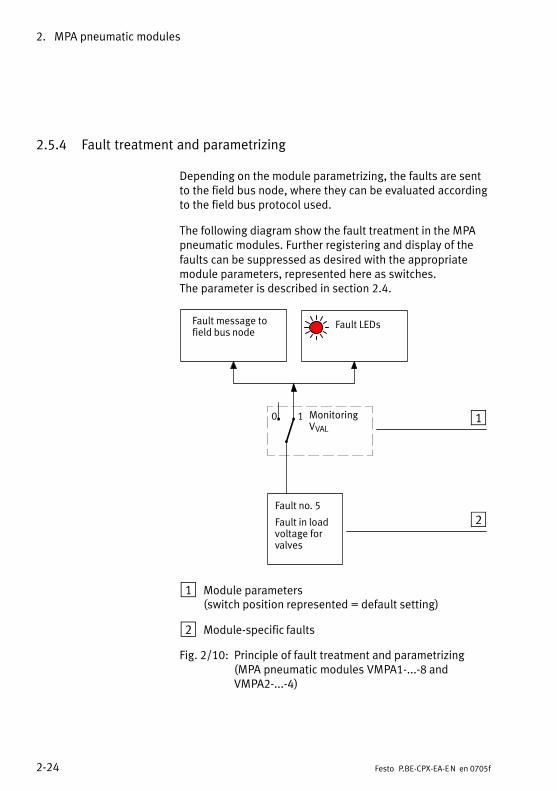
2.5.4 Fault treatment and parametrizing
Depending on the module parametrizing, the faults are sentto the field bus node, where they can be evaluated accordingto the field bus protocol used.
The following diagram show the fault treatment in the MPApneumatic modules. Further registering and display of thefaults can be suppressed as desired with the appropriatemodule parameters, represented here as switches. The parameter is described in section 2.4.
2Fault no. 5
Fault in loadvoltage forvalves
Fault message tofield bus node
MonitoringVVAL
Fault LEDs
10 1
1 Module parameters(switch position represented = default setting)
2 Module−specific faults
Fig.�2/10: Principle of fault treatment and parametrizing(MPA pneumatic modules VMPA1−...−8 andVMPA2−...−4)

Overview and connecting technology I/O modules
3−1Festo P.BE−CPX−EA−EN en 0705f
Chapter 3
Type CPX−AB−4−M12x2−5POLCPX−AB−4−M12x2−5POL−R
CPX−M−4−M12x2−5POL
CPX−AB−8−M8−3POLCPX−AB−8−M8−4POLCPX−AB−8−KL−4POLCPX−AB−1−SUB−BU−25POLCPX−AB−4−HARX2−4POLCPX−AB−4−M12−8POL
CPX−M−8−M12x2−5POL
3. Overview and connecting technology I/O modules
3−2 Festo P.BE−CPX−EA−EN en 0705f
Contents
3. Overview and connecting technology I/O modules 3−1 . . . . . . . . . . . . . . . . . . .
3.1 Components of an I/O module 3−3 . . . . . . . . . . . . . . . . . . . . . . . . . . . . . . . . . . . .
3.2 Connections 3−4 . . . . . . . . . . . . . . . . . . . . . . . . . . . . . . . . . . . . . . . . . . . . . . . . . . .
3.2.1 Display and connecting elements 3−8 . . . . . . . . . . . . . . . . . . . . . . . . . . .
3.2.2 Combinations of I/O modules and sub−bases 3−10 . . . . . . . . . . . . . . . . .
3.2.3 Connecting the cables and plugs to the sub−bases 3−13 . . . . . . . . . . . . .
3.3 Mounting 3−23 . . . . . . . . . . . . . . . . . . . . . . . . . . . . . . . . . . . . . . . . . . . . . . . . . . . . . .
3.3.1 Fitting the sub−bases 3−24 . . . . . . . . . . . . . . . . . . . . . . . . . . . . . . . . . . . . .
3.3.2 Fitting the screening/shield plates 3−28 . . . . . . . . . . . . . . . . . . . . . . . . . .

3. Overview and connecting technology I/O modules
3−3Festo P.BE−CPX−EA−EN en 0705f
3.1 Components of an I/O module
All I/O modules consist of three parts:
� The sub−base provides the electrical connections in theform of different sockets or terminal strips.
� The electronic module contains the printed circuit boardwith the electronics and the LED display of the I/O mod�ule. The electronic module is fitted into the sub−base andis connected to this and to the manifold sub−base bymeans of electric plug connectors.
� The manifold sub−base as the lower part of the housingprovides the mechanical and electrical link between themodule and the valve terminal.
1 Sub−base withspecificconnections
2 Electronicmodule
3 Manifoldsub−base
1
2
3
Fig.�3/1: Components of an I/O module (representation)
3. Overview and connecting technology I/O modules
3−4 Festo P.BE−CPX−EA−EN en 0705f
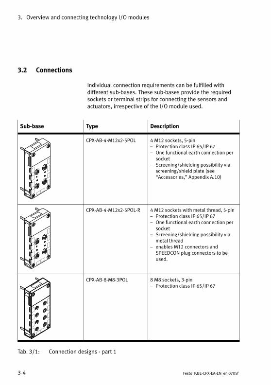
3.2 Connections
Individual connection requirements can be fulfilled with different sub−bases. These sub−bases provide the requiredsockets or terminal strips for connecting the sensors andactuators, irrespective of the I/O module used.
Sub−base Type Description
CPX−AB−4−M12x2−5POL 4 M12 sockets, 5−pin� Protection class IP 65/IP 67� One functional earth connection per
socket� Screening/shielding possibility via
screening/shield plate (see �Accessories," Appendix�A.10)
CPX−AB−4−M12x2−5POL−R 4 M12 sockets with metal thread, 5−pin� Protection class IP 65/IP 67� One functional earth connection per
socket� Screening/shielding possibility via
metal thread� enables M12 connectors and
SPEEDCON plug connectors to beused.
CPX−AB−8−M8−3POL 8 M8 sockets, 3−pin� Protection class IP 65/IP 67
Tab.�3/1: Connection designs − part 1
3. Overview and connecting technology I/O modules
3−5Festo P.BE−CPX−EA−EN en 0705f
Sub−base Type Description
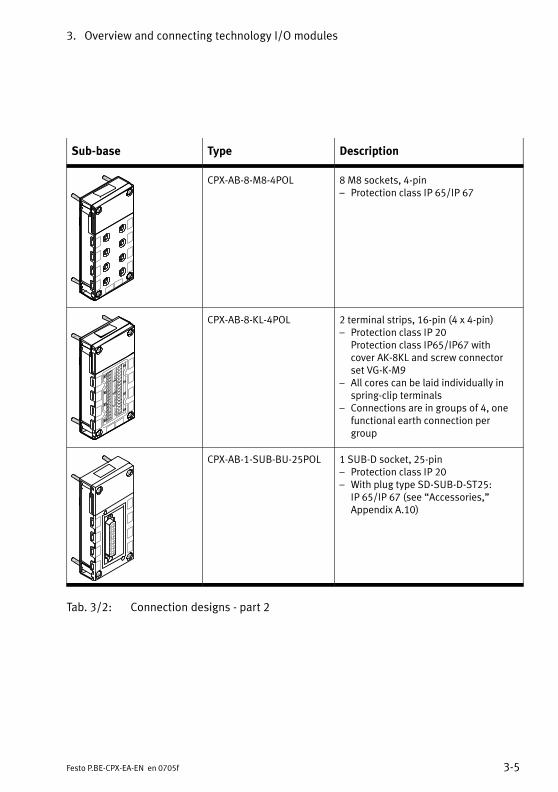
CPX−AB−8−M8−4POL 8 M8 sockets, 4−pin� Protection class IP 65/IP 67
CPX−AB−8−KL−4POL 2 terminal strips, 16−pin (4 x 4−pin)� Protection class IP 20
Protection class IP65/IP67 with cover AK−8KL and screw connectorset VG−K−M9
� All cores can be laid individually inspring−clip terminals
� Connections are in groups of 4, onefunctional earth connection pergroup
CPX−AB−1−SUB−BU−25POL 1 SUB−D socket, 25−pin� Protection class IP 20� With plug type SD−SUB−D−ST25:
IP�65/IP 67 (see �Accessories," Appendix�A.10)
Tab.�3/2: Connection designs − part 2
3. Overview and connecting technology I/O modules
3−6 Festo P.BE−CPX−EA−EN en 0705f
Sub−base Type Description
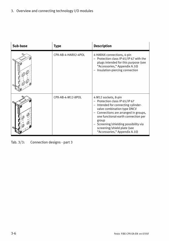
CPX−AB−4−HARX2−4POL 4 HARAX connections, 4−pin� Protection class IP 65/IP 67 with the
plugs intended for this purpose (see�Accessories," Appendix�A.10)
� Insulation−piercing connection
CPX−AB−4−M12−8POL 4 M12 sockets, 8−pin� Protection class IP 65/IP 67� Intended for connecting cylinder−
valve combination type DNCV� Connections are arranged in groups,
one functional−earth connection pergroup
� Screening/shielding possibility viascreening/shield plate (see �Accessories," Appendix�A.10)
Tab.�3/3: Connection designs − part 3
3. Overview and connecting technology I/O modules
3−7Festo P.BE−CPX−EA−EN en 0705f
Sub−base, Metal design
Type Description
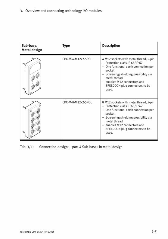
CPX−M−4−M12x2−5POL 4 M12 sockets with metal thread, 5−pin� Protection class IP 65/IP 67� One functional earth connection per
socket� Screening/shielding possibility via
metal thread� enables M12 connectors and
SPEEDCON plug connectors to beused.
CPX−M−8−M12x2−5POL 8 M12 sockets with metal thread, 5−pin� Protection class IP 65/IP 67� One functional earth connection per
socket� Screening/shielding possibility via
metal thread� enables M12 connectors and
SPEEDCON plug connectors to beused.
Tab.�3/1: Connection designs − part 4 Sub−bases in metal design
3. Overview and connecting technology I/O modules
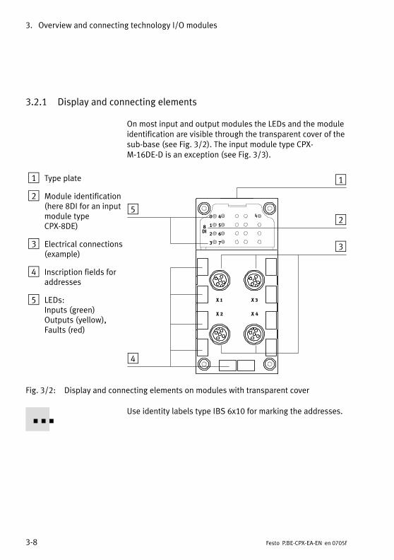
3−8 Festo P.BE−CPX−EA−EN en 0705f
3.2.1 Display and connecting elements
On most input and output modules the LEDs and the moduleidentification are visible through the transparent cover of thesub−base (see Fig.�3/2). The input module type CPX−M−16DE−D is an exception (see Fig.�3/3).
1 Type plate
2 Module identification(here 8DI for an inputmodule typeCPX−8DE)
3 Electrical connections(example)
4 Inscription fields foraddresses
5 LEDs:Inputs (green)Outputs (yellow),Faults (red)
0
1
2
3
8DI
4
5
6
7
1
2
3
4
5
Fig.�3/2: Display and connecting elements on modules with transparent cover
Use identity labels type IBS 6x10 for marking the addresses.

3. Overview and connecting technology I/O modules
3−9Festo P.BE−CPX−EA−EN en 0705f
1 Type plate
2 Electrical connections(example)
3 LEDs:Inputs (green)Outputs (yellow),Faults (red)
4 Holes for fasteningidentity labels
1
2
3
4
Fig.�3/3: Display and connecting elements on metal designs (here CPX−M−8−M12x2−5POL)
Use screws type CPX−M−M2,5X6−12X for fastening the identitylabels.
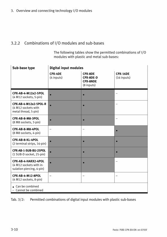
3. Overview and connecting technology I/O modules
3−10 Festo P.BE−CPX−EA−EN en 0705f
3.2.2 Combinations of I/O modules and sub−bases
The following tables show the permitted combinations of I/Omodules with plastic and metal sub−bases:
Sub−base type Digital input modules
CPX−4DE(4 inputs)
CPX−8DECPX−8DE−DCPX−8NDE(8 inputs)
CPX−16DE(16 inputs)
CPX−AB−4−M12x2−5POL(4 M12 sockets, 5−pin)
· · �
CPX−AB−4−M12x2−5POL−R(4 M12 sockets withmetal thread, 5−pin)
· · �
CPX−AB−8−M8−3POL(8 M8 sockets, 3−pin)
· · �
CPX−AB−8−M8−4POL(8 M8 sockets, 4−pin)
� � ·
CPX−AB−8−KL−4POL(2 terminal strips, 16−pin)
· · ·
CPX−AB−1−SUB−BU−25POL(1 SUB−D socket, 25−pin)
· · ·
CPX−AB−4−HARX2−4POL(4 M12 sockets with in�sulation piercing, 4−pin)
· · �
CPX−AB−4−M12−8POL(4 M12 sockets, 8−pin)
� � �
· Can be combined� Cannot be combined
Tab.�3/2: Permitted combinations of digital input modules with plastic sub−bases

3. Overview and connecting technology I/O modules
3−11Festo P.BE−CPX−EA−EN en 0705f
Sub−base type Digital output modules and multi I/O module
CPX−4DA(4 outputs)
CPX−8DA(8 outputs)
CPX−8DA−H(8 high currentoutputs)
CPX−8DE/8DA(8 inputs andoutputs)
CPX−AB−4−M12x2−5POL(4 M12 sockets, 5−pin)
· · � �
CPX−AB−4−M12x2−5POL−R(4 M12 sockets withmetal thread, 5−pin)
· · · �
CPX−AB−8−M8−3POL(8 M8 sockets, 3−pin)
· · � �
CPX−AB−8−M8−4POL(8 M8 sockets, 4−pin)
· · · �
CPX−AB−8−KL−4POL(2 terminal strips, 16−pin)
· · · ·
CPX−AB−1−SUB−BU−25POL(1 SUB−D socket, 25−pin)
· · · ·
CPX−AB−4−HARX2−4POL(4 M12 sockets with in�sulation piercing, 4−pin)
· · � �
CPX−AB−4−M12−8POL(4 M12 sockets, 8−pin)
� � � ·
· Can be combined� Cannot be combined
Tab.�3/3: Permitted combinations of digital output modules and multi I/O moduleswith plastic sub−bases
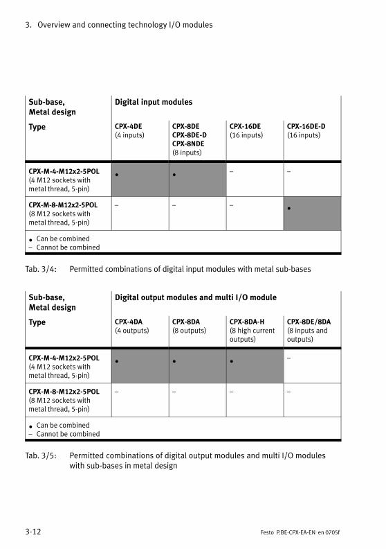
3. Overview and connecting technology I/O modules
3−12 Festo P.BE−CPX−EA−EN en 0705f
Sub−base, Metal design
Digital input modules
Type CPX−4DE(4 inputs)
CPX−8DECPX−8DE−DCPX−8NDE(8 inputs)
CPX−16DE(16 inputs)
CPX−16DE−D(16 inputs)
CPX−M−4−M12x2−5POL(4 M12 sockets withmetal thread, 5−pin)
· · � �
CPX−M−8−M12x2−5POL(8 M12 sockets withmetal thread, 5−pin)
� � � ·
· Can be combined� Cannot be combined
Tab.�3/4: Permitted combinations of digital input modules with metal sub−bases
Sub−base, Metal design
Digital output modules and multi I/O module
Type CPX−4DA(4 outputs)
CPX−8DA(8 outputs)
CPX−8DA−H(8 high currentoutputs)
CPX−8DE/8DA(8 inputs andoutputs)
CPX−M−4−M12x2−5POL(4 M12 sockets withmetal thread, 5−pin)
· · · �
CPX−M−8−M12x2−5POL(8 M12 sockets withmetal thread, 5−pin)
� � � �
· Can be combined� Cannot be combined
Tab.�3/5: Permitted combinations of digital output modules and multi I/O moduleswith sub−bases in metal design
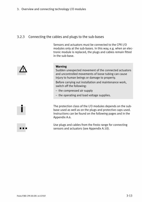
3. Overview and connecting technology I/O modules
3−13Festo P.BE−CPX−EA−EN en 0705f
3.2.3 Connecting the cables and plugs to the sub−bases
Sensors and actuators must be connected to the CPX I/Omodules only at the sub−bases. In this way, e.g. when an elec�tronic module is replaced, the plugs and cables remain fittedin the sub−base.
WarningSudden unexpected movement of the connected actuatorsand uncontrolled movements of loose tubing can causeinjury to human beings or damage to property.
Before carrying out installation and maintenance work,switch off the following:
� the compressed air supply
� the operating and load voltage supplies.
The protection class of the I/O modules depends on the sub−base used as well as on the plugs and protective caps used.Instructions can be found on the following pages and in theAppendix A.6.
Use plugs and cables from the Festo range for connectingsensors and actuators (see Appendix A.10).
3. Overview and connecting technology I/O modules
3−14 Festo P.BE−CPX−EA−EN en 0705f
Sub−bases CPX−AB−4−M12x2−5POL (−R)CPX−M−4−M12x2−5POL,CPX−M−8−M12x2−5POL
NoteIn order that completely fitted modules with sub−baseCPX−AB−4−M12x2−5POL (−R) or CPX−M−...−M12x2−5POL comply with protection class IP�65/IP 67:
· use plugs and cables from the Festo range for connect�ing the sensors and actuators (see Appendix A.10).
· Tighten the union nuts of the plugs at first by hand.
· Seal unused sockets with protective caps type ISK−M12(see Appendix A.10: Accessories).
The sub−bases with metal thread (type CPX−AB−4−M12x2−5POL−R and CPX−M−...−M12x2−5POL) enable fast lock�ing systems to be used, e.g. SPEEDCON from Phoenix Con�tact.
· When using fast locking systems follow the manufac�turer’s instructions in order to comply with protectionclass IP 65/IP 67.
Screening/shield
� On plugs without metal housing:
· Connect the cable screening to pin�5 (functional earth FE).
� On plugs with metal housing:
· Use the sub−base with metal thread (type CPX−AB−4−M12x2−5POL−R and CPX−M−...−M12x2−5POL). The metal thread of this sub−base is connected inter�nally with pin�5 (functional earth FE).
or
3. Overview and connecting technology I/O modules
3−15Festo P.BE−CPX−EA−EN en 0705f
· Connect the cable screening via the plug housing andthe screening plate to FE.
Screening plate type CPX−AB−S−4−12
Sub−base CPX−AB−4−M12x2−5POL (without metal thread) canbe combined with a screening/shield plate. Depending onwhat you have ordered, this may already be fitted on the sub−base.
Instructions on subsequent fitting of the screening/shieldplate can be found in section 3.3.2.
The electromagnetic compatibility can be improved withscreening/shield plates, e.g. in environments heavily sub�jected to interference or for analogue signals. For this pur�pose the screening/shield plates must be earthed at the flatcontact intended for this purpose as per DIN 46 244 B2,8−1(2.8 x 1 mm).
· Connect the earth cable of the screening/shield platewith low impedance to the functional earth connection(FE) as per Fig.�3/4.Screening/shield plates lying next to each other are con�nected together by spring clips and must not be con�nected individually to FE.
If the intended plugs are used (see �Accessories," AppendixA.10), the plug housing will be connected to functional earthvia the spring contacts on the screening/shield plate.
· Before fitting the plugs screw the spring contacts as far aspossible onto the thread of the plug.
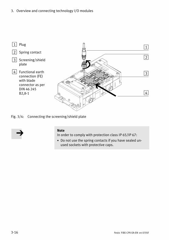
3. Overview and connecting technology I/O modules
3−16 Festo P.BE−CPX−EA−EN en 0705f
1 Plug
2 Spring contact
3 Screening/shieldplate
4 Functional earthconnection (FE)with bladeconnector as perDIN�46�245B2,8−1
1
2
3
4
Fig.�3/4: Connecting the screening/shield plate
NoteIn order to comply with protection class IP 65/IP 67:
· Do not use the spring contacts if you have sealed un�used sockets with protective caps.
3. Overview and connecting technology I/O modules
3−17Festo P.BE−CPX−EA−EN en 0705f
Sub−bases CPX−AB−8−M8−3POL and −4POL
NoteIn order that the completely fitted modules with sub−basesCPX−AB−8−M8−3POL and −4POL comply with protectionclass IP 65/IP 67:
· use plugs and cables from the Festo range for connect�ing the sensors and actuators (see Appendix A.10).
· Tighten the union nuts of the plugs at first by hand.
· Seal unused sockets with protective caps type ISK−M8(Accessories).
Sub−base CPX−AB−8−KL−4POL
The completely fitted sub−base CPX−AB−8−KL−4POL complieswith protection class IP 20.
Specifications of the cable terminals:
� Cable cross−sectional area: 0.08 ... 1.5 mm2
� Max. current: see chapter A.6
� Insulation removed: 5 ... 6 mm
Permitted copper conductors:
� single wire, multi−wire, fine wire, also with tin−plated indi�vidual cores
� Fine wire strands compressed
� Fine wire with core end sleeves (sealed against gas,crimped on)*)
� Fine wire with pin cable socket (sealed against gas,crimped on)*)
*) If necessary, use next smaller cross−sectional area
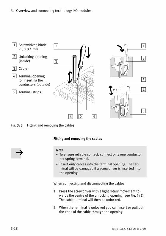
3. Overview and connecting technology I/O modules
3−18 Festo P.BE−CPX−EA−EN en 0705f
1 Screwdriver, blade2.5 x 0.4 mm
2 Unlocking opening(inside)
3 Cable
4 Terminal opening for inserting the conductors (outside)
5 Terminal strips
1
23
4
5
1
2
3
4 5
Fig.�3/5: Fitting and removing the cables
Fitting and removing the cables
Note· To ensure reliable contact, connect only one conductorper spring terminal.
· Insert only cables into the terminal opening. The ter�minal will be damaged if a screwdriver is inserted intothe opening.
When connecting and disconnecting the cables:
1. Press the screwdriver with a light rotary movement to�wards the centre of the unlocking opening (see Fig.�3/5).The cable terminal will then be unlocked.
2. When the terminal is unlocked you can insert or pull outthe ends of the cable through the opening.
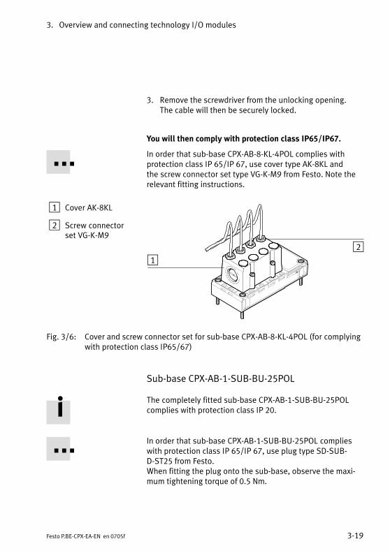
3. Overview and connecting technology I/O modules
3−19Festo P.BE−CPX−EA−EN en 0705f
3. Remove the screwdriver from the unlocking opening. The cable will then be securely locked.
You will then comply with protection class IP65/IP67.
In order that sub−base CPX−AB−8−KL−4POL complies withprotection class IP 65/IP 67, use cover type AK−8KL and the screw connector set type VG−K−M9 from Festo. Note therelevant fitting instructions.
1 Cover AK−8KL
2 Screw connectorset VG−K−M9
12
Fig.�3/6: Cover and screw connector set for sub−base CPX−AB−8−KL−4POL (for complyingwith protection class IP65/67)
Sub−base CPX−AB−1−SUB−BU−25POL
The completely fitted sub−base CPX−AB−1−SUB−BU−25POLcomplies with protection class IP 20.
In order that sub−base CPX−AB−1−SUB−BU−25POL complieswith protection class IP 65/IP 67, use plug type SD−SUB−D−ST25 from Festo.When fitting the plug onto the sub−base, observe the maxi�mum tightening torque of 0.5 Nm.
3. Overview and connecting technology I/O modules
3−20 Festo P.BE−CPX−EA−EN en 0705f
Sub−base CPX−AB−4−HARX2−4POL
NoteIn order that completely fitted modules with sub−baseCPX−AB−4−HARX2−4POL comply with protection class IP 65/IP 67:
· use plugs type SEA−GS−HAR−4POL from the Festo range(consisting of union nut, strain relief and splicing ring)for connecting sensors and actuators.
· Tighten the union nuts of the plugs at first by hand.
· Seal the unused connecting sockets with protectivecaps from Harting (see Accessories, Appendix�A.10).
Specifications of the cables for the sub−baseCPX−AB−4−HARX2−4POL:
� Cable cross−sectional area: 0.25 ... 0.5 mm2
� Strand cross−section: up to 0.1 mm
� Insulation material: PVC/PUR/PE
� Insulation thickness: max. 1.6 mm
� Core diameter: 1.2 mm ... 1.6 mm
� Cable outer diameter: 4.0 ... 5.1 mm

3. Overview and connecting technology I/O modules
3−21Festo P.BE−CPX−EA−EN en 0705f
Mounting
1 Cut the cable tolength and removethe coating. Push theunion nut and theseal insert onto theend of the cable.
2 Insert the ends of the core into the appropriate slots of the splicing ring.
3 Place the seal andthe splicing ring to�gether and cut off theprojecting core endsflush with the splicingring.
4 Insert the pre−fittedsplicing seal elementinto the contact sup�port in the sub−base.Screw in the unionnut as far as possible.
1
2
4
3
1
2
4
3
Fig.�3/7: Connecting the cables to sub−base CPX−AB
Dismantling
· Loosen the screw connector and remove the cores bypulling them out of the contacts.
The cores can be connected up to 10 times if the contactends are cut away each time (if the same core diameter isused). Cut off the used cable ends and repeat steps 2 to 4.
3. Overview and connecting technology I/O modules
3−22 Festo P.BE−CPX−EA−EN en 0705f
Sub−base CPX−AB−4−M12−8POL
NoteIn order that completely fitted modules with sub−baseCPX−AB−4−M12−8POL comply with protection class IP 65/IP 67:
· use cable type KM12−8GD8GS−2−PU from Festo for con�necting the cylinder−valve combination type DNCV orother sensors and actuators (see AppendixA.10)
· Tighten the union nuts of the plugs at first by hand.
· Seal unused sockets with protective caps type ISK−M12(Accessories).
Screening plate type CPX−AB−S−4−12
Sub−base CPX−AB−4−M12−8POL can be combined with ascreening plate. This can be ordered separately as an acces�sory.
Instructions on subsequent fitting of the screening/shieldplate can be found in section 3.3.2.Instructions on using the screening plates can be found withsub−base CPX−AB−4−M12x2−5POL.
3. Overview and connecting technology I/O modules
3−23Festo P.BE−CPX−EA−EN en 0705f
3.3 Mounting
WarningSudden unexpected movement of the connected actuatorsand uncontrolled movements of loose tubing can causeinjury to human beings or damage to property.
Before carrying out installation and maintenance work,switch off the following:
� the compressed air supply
� the operating and load voltage supplies.
CautionInappropriate handling can result in damage to the modules.
· Do not touch the electrical contacts of the modules.
· Observe the handling specifications for electrostaticallysensitive devices.
· Discharge yourself before installing or removing sub−assemblies to protect the sub−assemblies from staticdischarges.
Before the CPX terminal can be extended or converted, itmust first be unscrewed and dismantled. Instructions on thiscan be found in the CPX system manual.
The CPX terminal does not need to be dismantled when sub−bases or electronic modules are fitted or removed. This alsoapplies to the plugs and cables on the sub−base.
3. Overview and connecting technology I/O modules
3−24 Festo P.BE−CPX−EA−EN en 0705f
3.3.1 Fitting the sub−bases
NoteHandle all modules and components of the CPX terminalwith great care. Note especially the following:
· Screws must be fitted accurately (otherwise threads willbe damaged).Screws must be fastened at first only by hand. Screwsmust be placed so that the self−cutting threads can beused.
· The specified torques must be observed.
· Screw connections must be fitted free of offset andmechanical tension.
· Check the seals for damage (IP 65/IP 67).
· Connecting surfaces must be clean (to ensure sealingeffect, avoid leakage and contact faults).
The screw connection between the sub−base and the mani�fold sub−base is designed to withstand at least 10 fitting/removal cycles under observance of the instructions.
Observe also the installation instructions supplied withmodules and components ordered at a later stage.
CPX terminals are supplied from the factory completely fitted.It may be necessary to fit or remove the sub−bases for thefollowing reasons:
� for replacing the connections
� to simplify fitting the sensor plugs or cables.
It may be necessary to fit or remove the electronic modulesfor the following reasons:
� for changing the function of the I/O module (e.g. CPX−8DEinstead of CPX−4DE)
� for replacing defective electronic modules.

3. Overview and connecting technology I/O modules
3−25Festo P.BE−CPX−EA−EN en 0705f
Dismantling Dismantle the sub−base as follows (see Fig.�3/8):
1. Loosen the 4 screws in the relevant sub−base with a Torx screwdriver size T10.
2. Pull the sub−base carefully and without tilting away fromthe electrical plug connection of the electronic module.
Only in cases where the electronic module is to be removed:
· Pull the electronic module carefully and without tiltingaway from the contact rails of the manifold sub−base.
1 Sub−base
2 Screws
3 Electrical plugconnector
4 Electronicmodule
5 Contact rails
6 Manifoldsub−base
1
2
3
4
5
6
Fig.�3/8: Fitting/removing the I/O module (representation)
3. Overview and connecting technology I/O modules
3−26 Festo P.BE−CPX−EA−EN en 0705f
Fitting Fit the modules as follows (see Fig.�3/8):
Note· Please observe the instructions on combining I/O mod�ules and sub−bases in section 3.2.2.
· Please observe the instructions on combining and ar�ranging modules on the CPX terminal in the CPX systemmanual.
NoteWith a combination of sub−bases and manifold sub−baseswith metal on plastic or plastic on metal, always use theappropriate screws for the manifold sub−base (see Appen�dix A.10: Accessories):
� with plastic manifold sub−bases: thread−cutting screws
� with metal manifold sub−bases: screws with metricthread
Only in cases where the electronic module has been re�moved:
· Place the electronic module in the manifold sub−base.Make sure that the grooves with the contact terminals onthe bottom of the electronic module lie above the contactrails. Then push the electronic module carefully and with�out tilting as far as possible into the manifold sub−base.
Fitting the sub−bases:
1. Only CPX−M−8−M12x2−5POL: Observe the following asymmetrically arranged featuresfor the correct alignment of the components:
� the centre electrical plug connector and
� the optical wave guide for the error LED
3. Overview and connecting technology I/O modules
3−27Festo P.BE−CPX−EA−EN en 0705f
2. Align the sub−base over the manifold sub−base with theelectronic module. Make sure that the plug connectors ofthe sub−base are aligned exactly with the connectors ofthe electronic module. Then push the sub−base carefullyand without tilting onto the manifold sub−base.
3. Tighten the screws at first only by hand. Place the screwsso that the self−cutting threads can be used.Tighten the screws with a Torx screwdriver size T10 withtorque 0.9 ... 1.1�Nm.
3. Overview and connecting technology I/O modules
3−28 Festo P.BE−CPX−EA−EN en 0705f
3.3.2 Fitting the screening/shield plates
A screening plate type CPX−AB−S−4−12 can be fitted on sub−bases CPX−AB−4−M12x5−5POL and CPX−AB−4−M12−8POL. The sub−base must be removed before the terminal is fittedor dismantled.
Fitting Fit the screening plate as follows (see Fig.�3/9):
1. Dismantle the sub−base (see section 3.3.1).
2. Snap the spring clips of the screening/shield plate fromabove into the appropriate recesses on the dismantledsub−base.
3. Fit the sub−base.
Instructions on earthing the screening/shield plate can befound in section 3.2.3.
Dismantling The screening/shield plate must be removed in the oppositesequence to the fitting procedure.
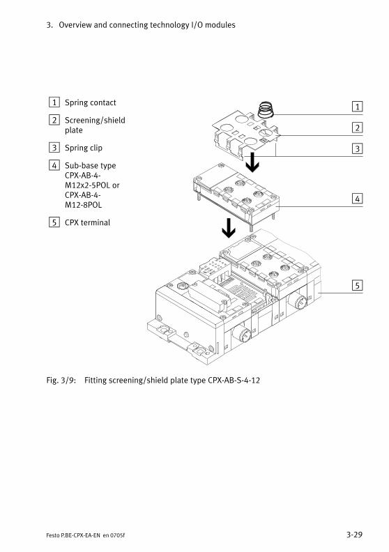
3. Overview and connecting technology I/O modules
3−29Festo P.BE−CPX−EA−EN en 0705f
1 Spring contact
2 Screening/shieldplate
3 Spring clip
4 Sub−base typeCPX−AB−4−M12x2−5POL orCPX−AB−4−M12−8POL
5 CPX terminal
1
2
3
4
5
Fig.�3/9: Fitting screening/shield plate type CPX−AB−S−4−12
3. Overview and connecting technology I/O modules
3−30 Festo P.BE−CPX−EA−EN en 0705f
Input modules
4−1Festo P.BE−CPX−EA−EN en 0705f
Chapter 4
Type CPX−4DE
CPX−8DE
CPX−8DE−D
CPX−16DE
CPX−M−16DE−D
CPX−8NDE
4. Input modules
4−2 Festo P.BE−CPX−EA−EN en 0705f
Contents
4. Input modules 4−1 . . . . . . . . . . . . . . . . . . . . . . . . . . . . . . . . . . . . . . . . . . . . . . . . .
4.1 Function of the input modules 4−3 . . . . . . . . . . . . . . . . . . . . . . . . . . . . . . . . . . . . .
4.2 Mounting 4−4 . . . . . . . . . . . . . . . . . . . . . . . . . . . . . . . . . . . . . . . . . . . . . . . . . . . . . .
4.3 Installation 4−5 . . . . . . . . . . . . . . . . . . . . . . . . . . . . . . . . . . . . . . . . . . . . . . . . . . . .
4.3.1 Input module CPX−4DE 4−6 . . . . . . . . . . . . . . . . . . . . . . . . . . . . . . . . . . .
4.3.2 Input module CPX−8DE 4−11 . . . . . . . . . . . . . . . . . . . . . . . . . . . . . . . . . . .
4.3.3 Input module CPX−8DE−D with channel diagnosis 4−16 . . . . . . . . . . . . . .
4.3.4 Input module CPX−16DE 4−21 . . . . . . . . . . . . . . . . . . . . . . . . . . . . . . . . . .
4.3.5 Input module CPX−16DE−D 4−24 . . . . . . . . . . . . . . . . . . . . . . . . . . . . . . . .
4.3.6 Input module CPX−8NDE 4−26 . . . . . . . . . . . . . . . . . . . . . . . . . . . . . . . . . .
4.4 Instructions on commissioning 4−31 . . . . . . . . . . . . . . . . . . . . . . . . . . . . . . . . . . . .
4.4.1 Parameters of the input modules type CPX−4DE, −8DE, −8DE−D, −16DE and−8NDE 4−31 . . . . . . . . . . . . . . . . . . . . . . . . . . . . . . . . . . . . . . . . . . . . . . . . .
4.5 Diagnosis 4−35 . . . . . . . . . . . . . . . . . . . . . . . . . . . . . . . . . . . . . . . . . . . . . . . . . . . . .
4.5.1 Fault messages of the input modules 4−35 . . . . . . . . . . . . . . . . . . . . . . .
4.5.2 LED display 4−37 . . . . . . . . . . . . . . . . . . . . . . . . . . . . . . . . . . . . . . . . . . . .
4.5.3 Fault treatment and parametrizing 4−40 . . . . . . . . . . . . . . . . . . . . . . . . . .
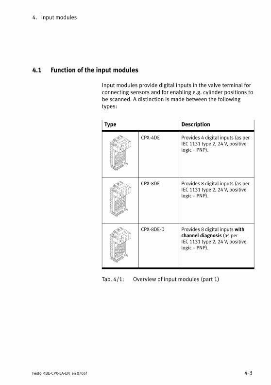
4. Input modules
4−3Festo P.BE−CPX−EA−EN en 0705f
4.1 Function of the input modules
Input modules provide digital inputs in the valve terminal forconnecting sensors and for enabling e.g. cylinder positions tobe scanned. A distinction is made between the followingtypes:
Type Description
CPX−4DE Provides 4 digital inputs (as perIEC 1131 type 2, 24�V, positivelogic � PNP).
CPX−8DE Provides 8 digital inputs (as perIEC 1131 type 2, 24�V, positivelogic � PNP).
CPX−8DE−D Provides 8 digital inputs withchannel diagnosis (as per IEC 1131 type 2, 24�V, positivelogic � PNP).
Tab.�4/1: Overview of input modules (part 1)
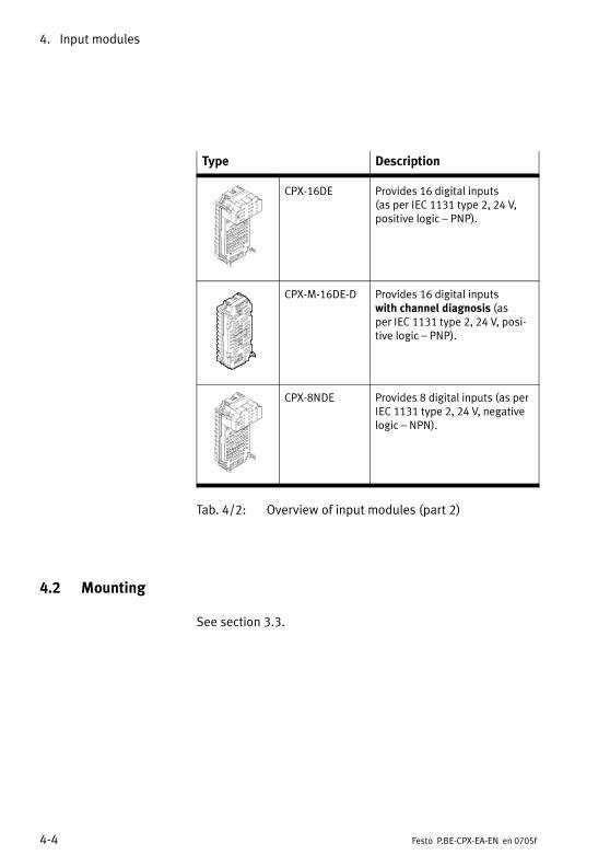
4. Input modules
4−4 Festo P.BE−CPX−EA−EN en 0705f
Type Description
CPX−16DE Provides 16 digital inputs (as per IEC 1131 type 2, 24�V,positive logic � PNP).
CPX−M−16DE−D Provides 16 digital inputs with channel diagnosis (as per IEC 1131 type 2, 24�V, posi�tive logic � PNP).
CPX−8NDE Provides 8 digital inputs (as perIEC 1131 type 2, 24�V, negativelogic � NPN).
Tab.�4/2: Overview of input modules (part 2)
4.2 Mounting
See section 3.3.
4. Input modules
4−5Festo P.BE−CPX−EA−EN en 0705f
4.3 Installation
WarningSudden unexpected movement of the connected actuatorsand uncontrolled movements of loose tubing can causeinjury to human beings or damage to property.
Before carrying out installation and maintenance work,switch off the following:
� the compressed air supply
� the operating and load voltage supplies.
In the following sections you will find the pin assignments ofthe input modules for the different sub−bases.
Instructions on connecting the cables and plugs to the sub−bases can be found in section 3.2.3.
Power supply
The 24 V sensor supply for the inputs as well as the powersupply for the electronics of the input modules is providedvia the operating voltage supply for the electronics/sensors(VEL/SEN).
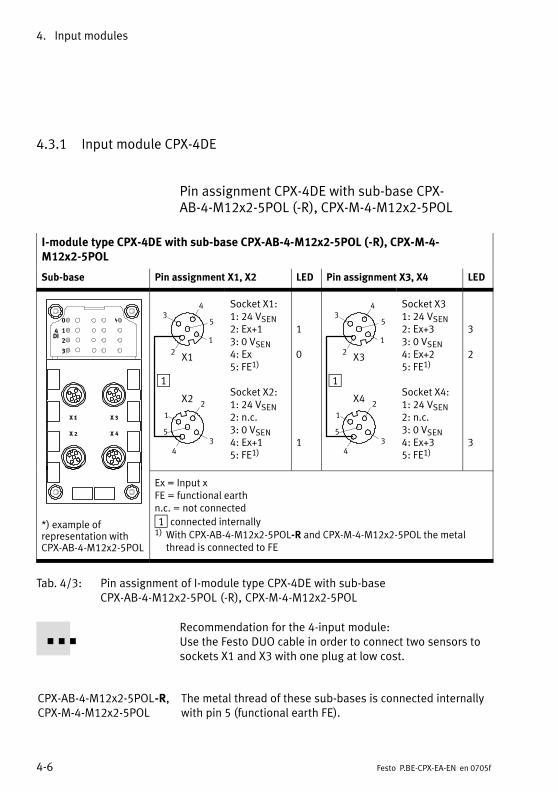
4. Input modules
4−6 Festo P.BE−CPX−EA−EN en 0705f
4.3.1 Input module CPX−4DE
Pin assignment CPX−4DE with sub−base CPX−AB−4−M12x2−5POL (−R), CPX−M−4−M12x2−5POL
I−module type CPX−4DE with sub−base CPX−AB−4−M12x2−5POL (−R), CPX−M−4−M12x2−5POL
Sub−base Pin assignment X1, X2 LED Pin assignment X3, X4 LED
0
1
2
3
4DI
1
2
2
3
3
1
1
5
5
4
4
X1
X2
Socket X1:1: 24 VSEN2: Ex+13: 0 VSEN4: Ex5: FE1)
Socket X2:1: 24 VSEN2: n.c.3: 0 VSEN4: Ex+15: FE1)
1
0
1
1
2
2
3
3
1
1
5
5
4
4
X3
X4
Socket X31: 24 VSEN2: Ex+33: 0 VSEN4: Ex+25: FE1)
Socket X4:1: 24 VSEN2: n.c.3: 0 VSEN4: Ex+35: FE1)
3
2
3
*) example ofrepresentation withCPX−AB−4−M12x2−5POL
Ex = Input xFE = functional earthn.c. = not connected
1 connected internally1) With CPX−AB−4−M12x2−5POL−R and CPX−M−4−M12x2−5POL the metal
thread is connected to FE
Tab.�4/3: Pin assignment of I−module type CPX−4DE with sub−baseCPX−AB−4−M12x2−5POL (−R), CPX−M−4−M12x2−5POL
Recommendation for the 4−input module:Use the Festo DUO cable in order to connect two sensors tosockets X1 and X3 with one plug at low cost.
CPX−AB−4−M12x2−5POL−R,CPX−M−4−M12x2−5POL
The metal thread of these sub−bases is connected internallywith pin�5 (functional earth FE).
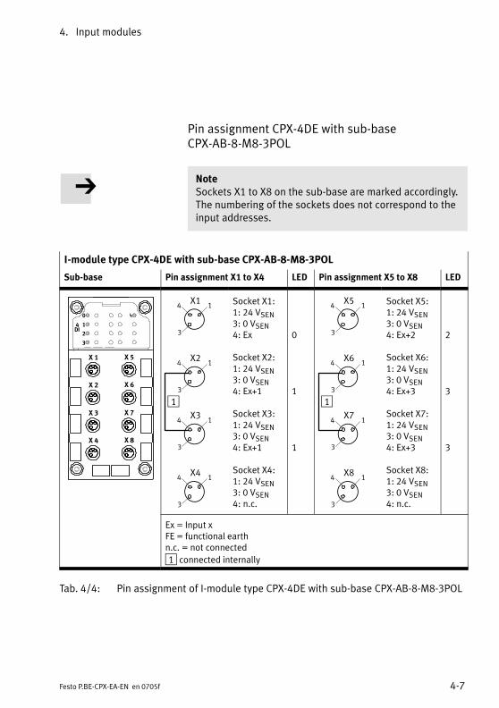
4. Input modules
4−7Festo P.BE−CPX−EA−EN en 0705f
Pin assignment CPX−4DE with sub−base CPX−AB−8−M8−3POL
NoteSockets X1 to X8 on the sub−base are marked accordingly.The numbering of the sockets does not correspond to theinput addresses.
I−module type CPX−4DE with sub−base CPX−AB−8−M8−3POL
Sub−base Pin assignment X1 to X4 LED Pin assignment X5 to X8 LED
0
1
2
3
4DI
X�1
X�2
X�3
X�4
X�5
X�6
X�7
X�8
1
X14 1
3
X24 1
3
X34 1
3
X44 1
3
Socket X1:1: 24 VSEN3: 0 VSEN4: Ex
Socket X2:1: 24 VSEN3: 0 VSEN4: Ex+1
Socket X3:1: 24 VSEN3: 0 VSEN4: Ex+1
Socket X4:1: 24 VSEN3: 0 VSEN4: n.c.
0
1
1
1
X54 1
3
X64 1
3
X74 1
3
X84 1
3
Socket X5:1: 24 VSEN3: 0 VSEN4: Ex+2
Socket X6:1: 24 VSEN3: 0 VSEN4: Ex+3
Socket X7:1: 24 VSEN3: 0 VSEN4: Ex+3
Socket X8:1: 24 VSEN3: 0 VSEN4: n.c.
2
3
3
Ex = Input xFE = functional earthn.c. = not connected
1 connected internally
Tab.�4/4: Pin assignment of I−module type CPX−4DE with sub−base CPX−AB−8−M8−3POL
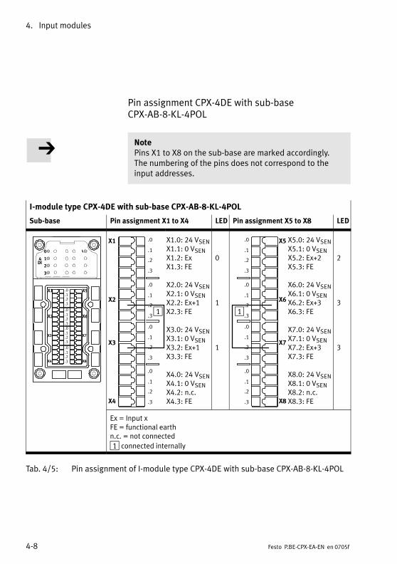
4. Input modules
4−8 Festo P.BE−CPX−EA−EN en 0705f
Pin assignment CPX−4DE with sub−base CPX−AB−8−KL−4POL
NotePins X1 to X8 on the sub−base are marked accordingly.The numbering of the pins does not correspond to theinput addresses.
I−module type CPX−4DE with sub−base CPX−AB−8−KL−4POL
Sub−base Pin assignment X1 to X4 LED Pin assignment X5 to X8 LED
0
1
2
3
4DI
X1
X2
X3
X4
X5
X6
X7
X8
.0
.1
.2
.3
.0
.1
.2
.3
.0
.1
.2
.3
.0
.1
.2
.3
X1
X2
X3
X4
.0
.1
.2
.3
.0
.1
.2
.3
.0
.1
.2
.3
.0
.1
.2
.3
1
X1.0: 24 VSENX1.1: 0 VSENX1.2: ExX1.3: FE
X2.0: 24 VSENX2.1: 0 VSENX2.2: Ex+1X2.3: FE
X3.0: 24 VSENX3.1: 0 VSENX3.2: Ex+1X3.3: FE
X4.0: 24 VSENX4.1: 0 VSENX4.2: n.c.X4.3: FE
0
1
1
X5
X6
X7
X8
.0
.1
.2
.3
.0
.1
.2
.3
.0
.1
.2
.3
.0
.1
.2
.3
1
X5.0: 24 VSENX5.1: 0 VSENX5.2: Ex+2X5.3: FE
X6.0: 24 VSENX6.1: 0 VSENX6.2: Ex+3X6.3: FE
X7.0: 24 VSENX7.1: 0 VSENX7.2: Ex+3X7.3: FE
X8.0: 24 VSENX8.1: 0 VSENX8.2: n.c.X8.3: FE
2
3
3
Ex = Input xFE = functional earthn.c. = not connected
1 connected internally
Tab.�4/5: Pin assignment of I−module type CPX−4DE with sub−base CPX−AB−8−KL−4POL
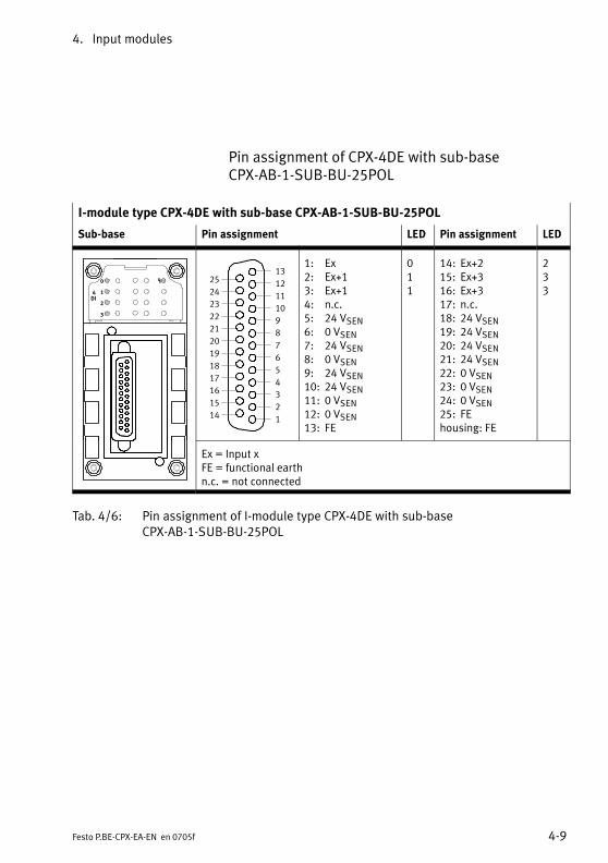
4. Input modules
4−9Festo P.BE−CPX−EA−EN en 0705f
Pin assignment of CPX−4DE with sub−base CPX−AB−1−SUB−BU−25POL
I−module type CPX−4DE with sub−base CPX−AB−1−SUB−BU−25POL
Sub−base Pin assignment LED Pin assignment LED
0
1
2
3
4DI
1
2
3
4
5
6
7
8
9
10
11
12
13
14
15
16
17
18
19
20
21
22
23
24
25
1: Ex2: Ex+13: Ex+14: n.c.5: 24 VSEN6: 0 VSEN7: 24 VSEN8: 0 VSEN9: 24 VSEN10: 24 VSEN11: 0 VSEN12: 0 VSEN13: FE
011
14: Ex+215: Ex+316: Ex+317: n.c.18: 24 VSEN19: 24 VSEN20: 24 VSEN21: 24 VSEN22: 0 VSEN23: 0 VSEN24: 0 VSEN25: FEhousing: FE
233
Ex = Input xFE = functional earthn.c. = not connected
Tab.�4/6: Pin assignment of I−module type CPX−4DE with sub−baseCPX−AB−1−SUB−BU−25POL

4. Input modules
4−10 Festo P.BE−CPX−EA−EN en 0705f
Pin assignment CPX−4DE with sub−base CPX−AB−4−HARX2−4POL
I−module type CPX−4DE with sub−base CPX−AB−4−HARX2−4POL
Sub−base Pin assignment X1, X2 LED Pin assignment X3, X4 LED
0
1
2
3
4DI
1
23
14
X1
X22 3
1 4
Socket X1:1: 24 VSEN2: Ex+13: 0 VSEN4: Ex
Socket X2:1: 24 VSEN2: n.c.3: 0 VSEN4: Ex+1
1
0
1
1
23
14
X3
X42 3
1 4
Socket X31: 24 VSEN2: Ex+33: 0 VSEN4: Ex+2
Socket X4:1: 24 VSEN2: n.c.3: 0 VSEN4: Ex+3
3
2
3
Ex = Input xFE = functional earthn.c. = not connected
1 connected internally
Tab.�4/7: Pin assignment of I−module type CPX−4DE with sub−base CPX−AB−4−HARX2−4POL
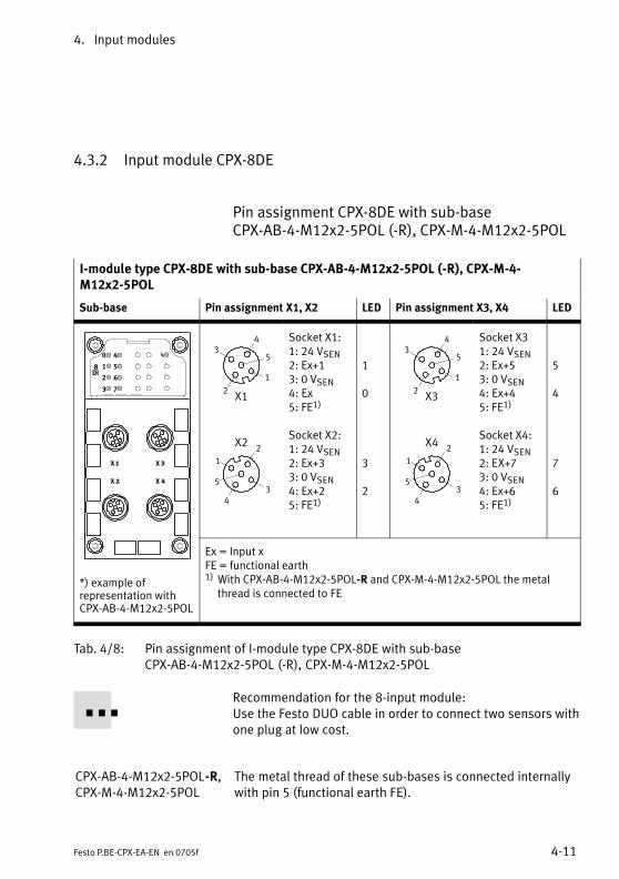
4. Input modules
4−11Festo P.BE−CPX−EA−EN en 0705f
4.3.2 Input module CPX−8DE
Pin assignment CPX−8DE with sub−base CPX−AB−4−M12x2−5POL (−R), CPX−M−4−M12x2−5POL
I−module type CPX−8DE with sub−base CPX−AB−4−M12x2−5POL (−R), CPX−M−4−M12x2−5POL
Sub−base Pin assignment X1, X2 LED Pin assignment X3, X4 LED
0
1
2
3
8DI
4
5
6
7 2
2
3
3
1
1
5
5
4
4
X1
X2
Socket X1:1: 24 VSEN2: Ex+13: 0 VSEN4: Ex5: FE1)
Socket X2:1: 24 VSEN2: Ex+33: 0 VSEN4: Ex+25: FE1)
1
0
3
2
2
2
3
3
1
1
5
5
4
4
X3
X4
Socket X31: 24 VSEN2: Ex+53: 0 VSEN4: Ex+45: FE1)
Socket X4:1: 24 VSEN2: EX+73: 0 VSEN4: Ex+65: FE1)
5
4
7
6
*) example ofrepresentation withCPX−AB−4−M12x2−5POL
Ex = Input xFE = functional earth1) With CPX−AB−4−M12x2−5POL−R and CPX−M−4−M12x2−5POL the metal
thread is connected to FE
Tab.�4/8: Pin assignment of I−module type CPX−8DE with sub−baseCPX−AB−4−M12x2−5POL (−R), CPX−M−4−M12x2−5POL
Recommendation for the 8−input module:Use the Festo DUO cable in order to connect two sensors withone plug at low cost.
CPX−AB−4−M12x2−5POL−R,CPX−M−4−M12x2−5POL
The metal thread of these sub−bases is connected internallywith pin�5 (functional earth FE).

4. Input modules
4−12 Festo P.BE−CPX−EA−EN en 0705f
Pin assignment CPX−8DE with sub−base CPX−AB−8−M8−3POL
I−module type CPX−8DE with sub−base CPX−AB−8−M8−3POL
Sub−base Pin assignment X1 to X4 LED Pin assignment X5 to X8 LED
0
1
2
3
8DI
4
5
6
7
X�1
X�2
X�3
X�4
X�5
X�6
X�7
X�8
X14 1
3
X24 1
3
X34 1
3
X44 1
3
Socket X1:1: 24 VSEN3: 0 VSEN4: Ex
Socket X2:1: 24 VSEN3: 0 VSEN4: Ex+1
Socket X3:1: 24 VSEN3: 0 VSEN4: Ex+2
Socket X4:1: 24 VSEN3: 0 VSEN4: Ex+3
0
1
2
3
X54 1
3
X64 1
3
X74 1
3
X84 1
3
Socket X5:1: 24 VSEN3: 0 VSEN4: Ex+4
Socket X6:1: 24 VSEN3: 0 VSEN4: Ex+5
Socket X7:1: 24 VSEN3: 0 VSEN4: Ex+6
Socket X8:1: 24 VSEN3: 0 VSEN4: Ex+7
4
5
6
7
Ex = Input xFE = functional earth
Tab.�4/9: Pin assignment of I−module type CPX−8DE with sub−base CPX−AB−8−M8−3POL
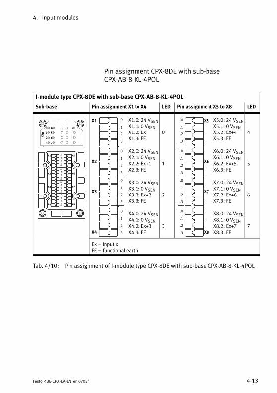
4. Input modules
4−13Festo P.BE−CPX−EA−EN en 0705f
Pin assignment CPX−8DE with sub−base CPX−AB−8−KL−4POL
I−module type CPX−8DE with sub−base CPX−AB−8−KL−4POL
Sub−base Pin assignment X1 to X4 LED Pin assignment X5 to X8 LED
0
1
2
3
8DI
4
5
6
7
X1
X2
X3
X4
X5
X6
X7
X8
.0
.1
.2
.3
.0
.1
.2
.3
.0
.1
.2
.3
.0
.1
.2
.3
X1
X2
X3
X4
.0
.1
.2
.3
.0
.1
.2
.3
.0
.1
.2
.3
.0
.1
.2
.3
X1.0: 24 VSENX1.1: 0 VSENX1.2: ExX1.3: FE
X2.0: 24 VSENX2.1: 0 VSENX2.2: Ex+1X2.3: FE
X3.0: 24 VSENX3.1: 0 VSENX3.2: Ex+2X3.3: FE
X4.0: 24 VSENX4.1: 0 VSENX4.2: Ex+3X4.3: FE
0
1
2
3
X5
X6
X7
X8
.0
.1
.2
.3
.0
.1
.2
.3
.0
.1
.2
.3
.0
.1
.2
.3
X5.0: 24 VSENX5.1: 0 VSENX5.2: Ex+4X5.3: FE
X6.0: 24 VSENX6.1: 0 VSENX6.2: Ex+5X6.3: FE
X7.0: 24 VSENX7.1: 0 VSENX7.2: Ex+6X7.3: FE
X8.0: 24 VSENX8.1: 0 VSENX8.2: Ex+7X8.3: FE
4
5
6
7
Ex = Input xFE = functional earth
Tab.�4/10: Pin assignment of I−module type CPX−8DE with sub−base CPX−AB−8−KL−4POL
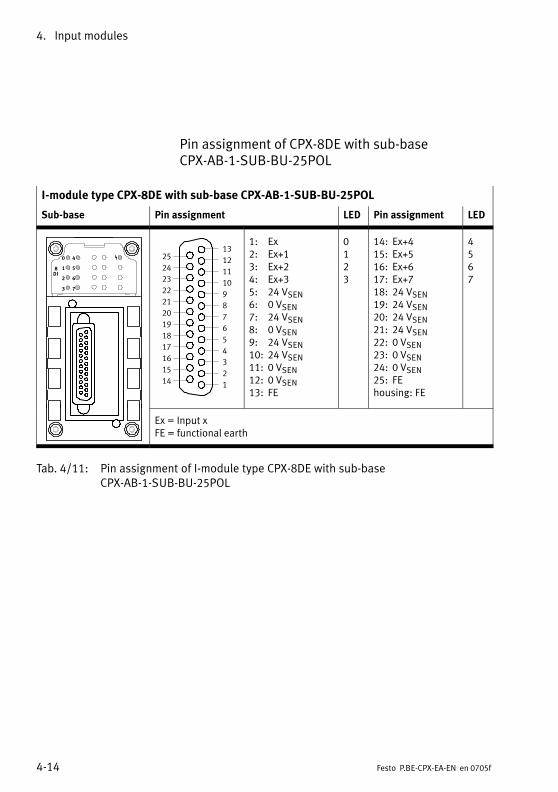
4. Input modules
4−14 Festo P.BE−CPX−EA−EN en 0705f
Pin assignment of CPX−8DE with sub−base CPX−AB−1−SUB−BU−25POL
I−module type CPX−8DE with sub−base CPX−AB−1−SUB−BU−25POL
Sub−base Pin assignment LED Pin assignment LED
0
1
2
3
8DI
4
5
6
7
1
2
3
4
5
6
7
8
9
10
11
12
13
14
15
16
17
18
19
20
21
22
23
24
25
1: Ex2: Ex+13: Ex+24: Ex+35: 24 VSEN6: 0 VSEN7: 24 VSEN8: 0 VSEN9: 24 VSEN10: 24 VSEN11: 0 VSEN12: 0 VSEN13: FE
0123
14: Ex+415: Ex+516: Ex+617: Ex+718: 24 VSEN19: 24 VSEN20: 24 VSEN21: 24 VSEN22: 0 VSEN23: 0 VSEN24: 0 VSEN25: FEhousing: FE
4567
Ex = Input xFE = functional earth
Tab.�4/11: Pin assignment of I−module type CPX−8DE with sub−baseCPX−AB−1−SUB−BU−25POL
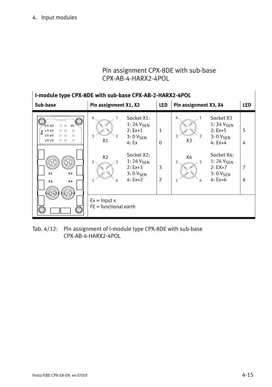
4. Input modules
4−15Festo P.BE−CPX−EA−EN en 0705f
Pin assignment CPX−8DE with sub−base CPX−AB−4−HARX2−4POL
I−module type CPX−8DE with sub−base CPX−AB−2−HARX2−4POL
Sub−base Pin assignment X1, X2 LED Pin assignment X3, X4 LED
0
1
2
3
8DI
4
5
6
7
23
14
X1
X22 3
1 4
Socket X1:1: 24 VSEN2: Ex+13: 0 VSEN4: Ex
Socket X2:1: 24 VSEN2: Ex+33: 0 VSEN4: Ex+2
1
0
3
2
23
14
X3
X42 3
1 4
Socket X31: 24 VSEN2: Ex+53: 0 VSEN4: Ex+4
Socket X4:1: 24 VSEN2: EX+73: 0 VSEN4: Ex+6
5
4
7
6
Ex = Input xFE = functional earth
Tab.�4/12: Pin assignment of I−module type CPX−8DE with sub−base CPX−AB−4−HARX2−4POL
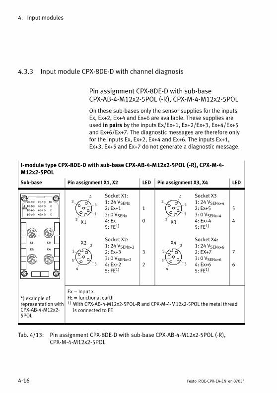
4. Input modules
4−16 Festo P.BE−CPX−EA−EN en 0705f
4.3.3 Input module CPX−8DE−D with channel diagnosis
Pin assignment CPX−8DE−D with sub−base CPX−AB−4−M12x2−5POL (−R), CPX−M−4−M12x2−5POL
On these sub−bases only the sensor supplies for the inputsEx, Ex+2, Ex+4 and Ex+6 are available. These supplies areused in pairs by the inputs Ex/Ex+1, Ex+2/Ex+3, Ex+4/Ex+5and Ex+6/Ex+7. The diagnostic messages are therefore onlyfor the inputs Ex, Ex+2, Ex+4 and Ex+6. The inputs Ex+1,Ex+3, Ex+5 and Ex+7 do not generate a diagnostic message.
I−module type CPX−8DE−D with sub−base CPX−AB−4−M12x2−5POL (−R), CPX−M−4−M12x2−5POL
Sub−base Pin assignment X1, X2 LED Pin assignment X3, X4 LED
2
2
3
3
1
1
5
5
4
4
X1
X2
Socket X1:1: 24 VSENx2: Ex+13: 0 VSENx4: Ex5: FE1)
Socket X2:1: 24 VSENx+22: Ex+33: 0 VSENx+24: Ex+25: FE1)
1
0
3
2
2
2
3
3
1
1
5
5
4
4
X3
X4
Socket X31: 24 VSENx+42: Ex+53: 0 VSENx+44: Ex+45: FE1)
Socket X4:1: 24 VSENx+62: EX+73: 0 VSENx+64: Ex+65: FE1)
5
4
7
6
*) example ofrepresentation withCPX−AB−4−M12x2−5POL
Ex = Input xFE = functional earth1) With CPX−AB−4−M12x2−5POL−R and CPX−M−4−M12x2−5POL the metal thread
is connected to FE
Tab.�4/13: Pin assignment CPX−8DE−D with sub−base CPX−AB−4−M12x2−5POL (−R), CPX−M−4−M12x2−5POL
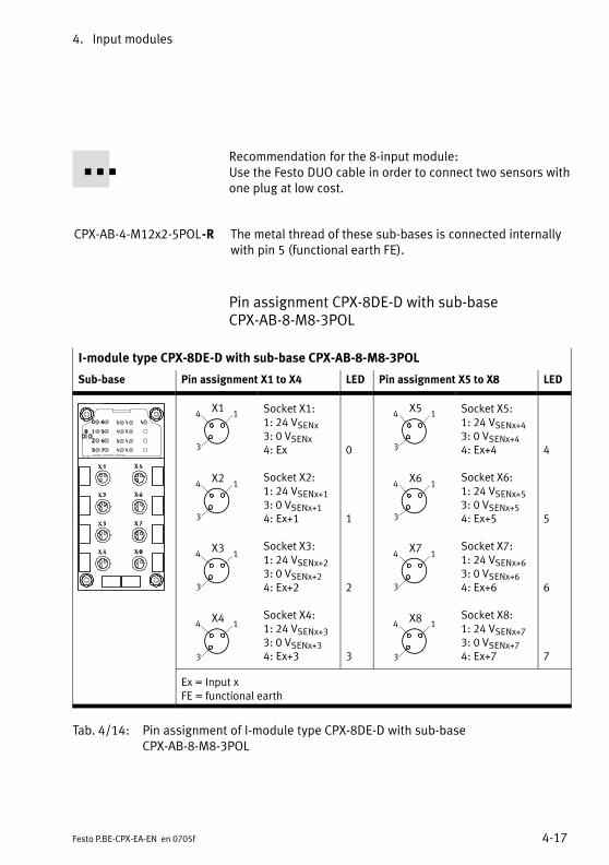
4. Input modules
4−17Festo P.BE−CPX−EA−EN en 0705f
Recommendation for the 8−input module:Use the Festo DUO cable in order to connect two sensors withone plug at low cost.
CPX−AB−4−M12x2−5POL−R The metal thread of these sub−bases is connected internallywith pin�5 (functional earth FE).
Pin assignment CPX−8DE−D with sub−base CPX−AB−8−M8−3POL
I−module type CPX−8DE−D with sub−base CPX−AB−8−M8−3POL
Sub−base Pin assignment X1 to X4 LED Pin assignment X5 to X8 LED
X14 1
3
X24 1
3
X34 1
3
X44 1
3
Socket X1:1: 24 VSENx3: 0 VSENx4: Ex
Socket X2:1: 24 VSENx+13: 0 VSENx+14: Ex+1
Socket X3:1: 24 VSENx+23: 0 VSENx+24: Ex+2
Socket X4:1: 24 VSENx+33: 0 VSENx+34: Ex+3
0
1
2
3
X54 1
3
X64 1
3
X74 1
3
X84 1
3
Socket X5:1: 24 VSENx+43: 0 VSENx+44: Ex+4
Socket X6:1: 24 VSENx+53: 0 VSENx+54: Ex+5
Socket X7:1: 24 VSENx+63: 0 VSENx+64: Ex+6
Socket X8:1: 24 VSENx+73: 0 VSENx+74: Ex+7
4
5
6
7
Ex = Input xFE = functional earth
Tab.�4/14: Pin assignment of I−module type CPX−8DE−D with sub−base CPX−AB−8−M8−3POL
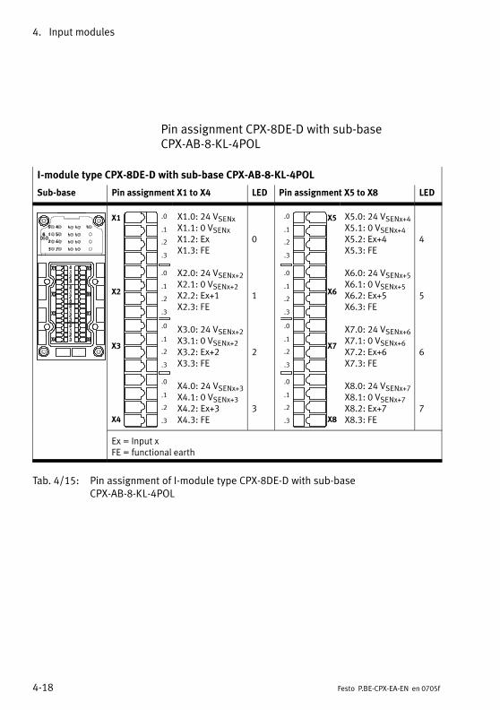
4. Input modules
4−18 Festo P.BE−CPX−EA−EN en 0705f
Pin assignment CPX−8DE−D with sub−base CPX−AB−8−KL−4POL
I−module type CPX−8DE−D with sub−base CPX−AB−8−KL−4POL
Sub−base Pin assignment X1 to X4 LED Pin assignment X5 to X8 LED
X1
X2
X3
X4
.0
.1
.2
.3
.0
.1
.2
.3
.0
.1
.2
.3
.0
.1
.2
.3
X1.0: 24 VSENxX1.1: 0 VSENxX1.2: ExX1.3: FE
X2.0: 24 VSENx+2X2.1: 0 VSENx+2X2.2: Ex+1X2.3: FE
X3.0: 24 VSENx+2X3.1: 0 VSENx+2X3.2: Ex+2X3.3: FE
X4.0: 24 VSENx+3X4.1: 0 VSENx+3X4.2: Ex+3X4.3: FE
0
1
2
3
X5
X6
X7
X8
.0
.1
.2
.3
.0
.1
.2
.3
.0
.1
.2
.3
.0
.1
.2
.3
X5.0: 24 VSENx+4X5.1: 0 VSENx+4X5.2: Ex+4X5.3: FE
X6.0: 24 VSENx+5X6.1: 0 VSENx+5X6.2: Ex+5X6.3: FE
X7.0: 24 VSENx+6X7.1: 0 VSENx+6X7.2: Ex+6X7.3: FE
X8.0: 24 VSENx+7X8.1: 0 VSENx+7X8.2: Ex+7X8.3: FE
4
5
6
7
Ex = Input xFE = functional earth
Tab.�4/15: Pin assignment of I−module type CPX−8DE−D with sub−base CPX−AB−8−KL−4POL
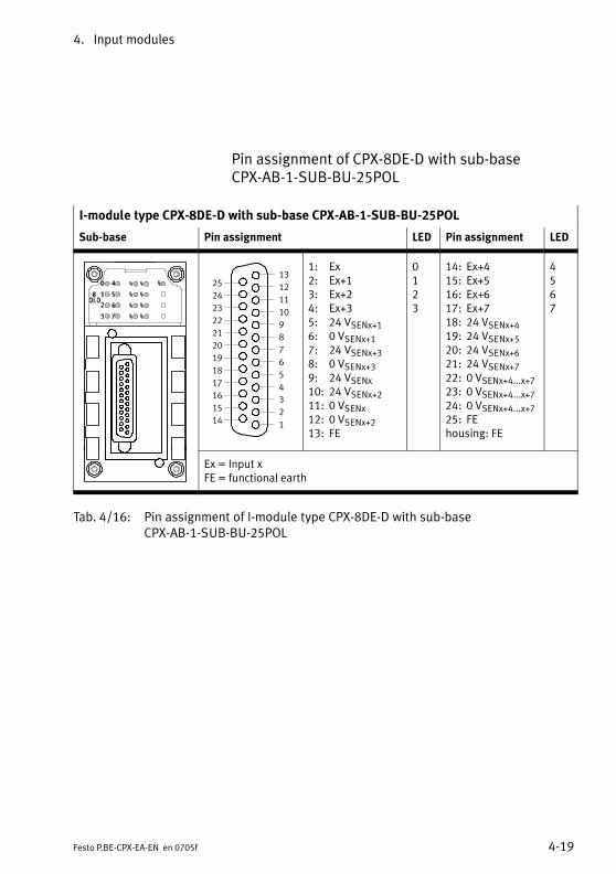
4. Input modules
4−19Festo P.BE−CPX−EA−EN en 0705f
Pin assignment of CPX−8DE−D with sub−base CPX−AB−1−SUB−BU−25POL
I−module type CPX−8DE−D with sub−base CPX−AB−1−SUB−BU−25POL
Sub−base Pin assignment LED Pin assignment LED
1
2
3
4
5
6
7
8
9
10
11
12
13
14
15
16
17
18
19
20
21
22
23
24
25
1: Ex2: Ex+13: Ex+24: Ex+35: 24 VSENx+16: 0 VSENx+17: 24 VSENx+38: 0 VSENx+39: 24 VSENx10: 24 VSENx+211: 0 VSENx12: 0 VSENx+213: FE
0123
14: Ex+415: Ex+516: Ex+617: Ex+718: 24 VSENx+419: 24 VSENx+520: 24 VSENx+621: 24 VSENx+722: 0 VSENx+4...x+723: 0 VSENx+4...x+724: 0 VSENx+4...x+725: FEhousing: FE
4567
Ex = Input xFE = functional earth
Tab.�4/16: Pin assignment of I−module type CPX−8DE−D with sub−baseCPX−AB−1−SUB−BU−25POL
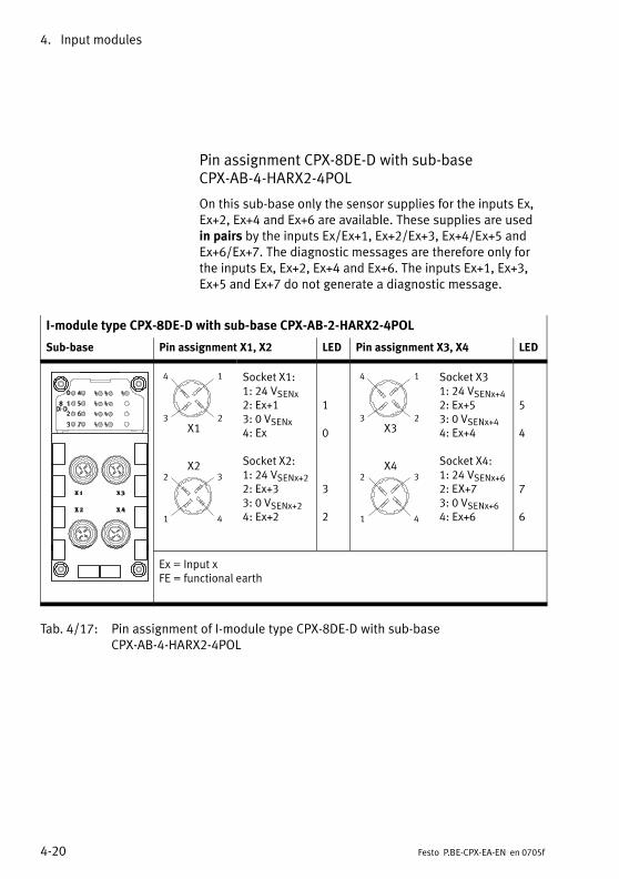
4. Input modules
4−20 Festo P.BE−CPX−EA−EN en 0705f
Pin assignment CPX−8DE−D with sub−base CPX−AB−4−HARX2−4POL
On this sub−base only the sensor supplies for the inputs Ex,Ex+2, Ex+4 and Ex+6 are available. These supplies are usedin pairs by the inputs Ex/Ex+1, Ex+2/Ex+3, Ex+4/Ex+5 andEx+6/Ex+7. The diagnostic messages are therefore only forthe inputs Ex, Ex+2, Ex+4 and Ex+6. The inputs Ex+1, Ex+3,Ex+5 and Ex+7 do not generate a diagnostic message.
I−module type CPX−8DE−D with sub−base CPX−AB−2−HARX2−4POL
Sub−base Pin assignment X1, X2 LED Pin assignment X3, X4 LED
23
14
X1
X22 3
1 4
Socket X1:1: 24 VSENx2: Ex+13: 0 VSENx4: Ex
Socket X2:1: 24 VSENx+22: Ex+33: 0 VSENx+24: Ex+2
1
0
3
2
23
14
X3
X42 3
1 4
Socket X31: 24 VSENx+42: Ex+53: 0 VSENx+44: Ex+4
Socket X4:1: 24 VSENx+62: EX+73: 0 VSENx+64: Ex+6
5
4
7
6
Ex = Input xFE = functional earth
Tab.�4/17: Pin assignment of I−module type CPX−8DE−D with sub−base CPX−AB−4−HARX2−4POL
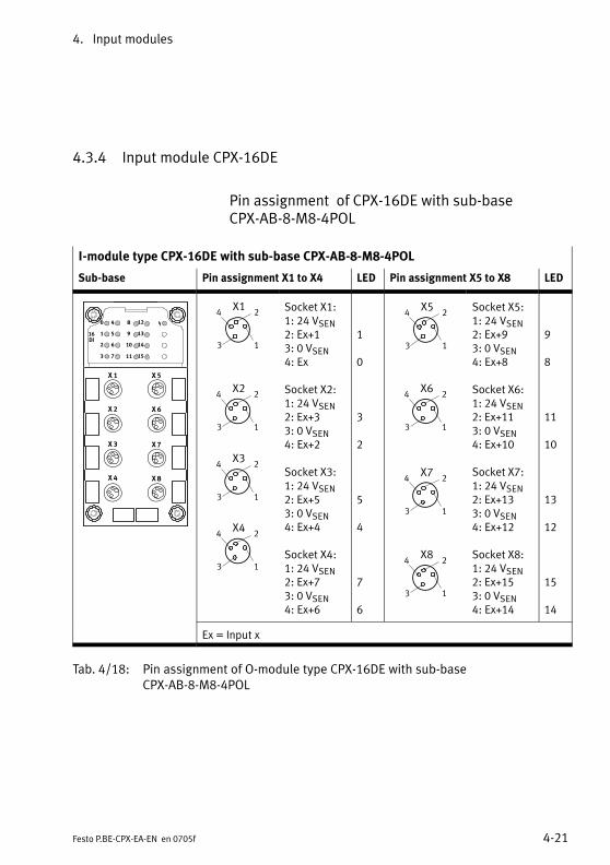
4. Input modules
4−21Festo P.BE−CPX−EA−EN en 0705f
4.3.4 Input module CPX−16DE
Pin assignment of CPX−16DE with sub−base CPX−AB−8−M8−4POL
I−module type CPX−16DE with sub−base CPX−AB−8−M8−4POL
Sub−base Pin assignment X1 to X4 LED Pin assignment X5 to X8 LED
X�1
X�2
X�3
X�4
X�5
X�6
X�7
X�8
0
1
2
3
16DI
4
5
6
7
�8
�9
10
11
12
13
14
15
X34 2
3 1
X24 2
3 1
X44 2
3 1
X14 2
3 1
Socket X1:1: 24 VSEN2: Ex+13: 0 VSEN4: Ex
Socket X2:1: 24 VSEN2: Ex+33: 0 VSEN4: Ex+2
Socket X3:1: 24 VSEN2: Ex+53: 0 VSEN4: Ex+4
Socket X4:1: 24 VSEN2: Ex+73: 0 VSEN4: Ex+6
1
0
3
2
5
4
7
6
X54 2
3 1
X64 2
3 1
X74 2
3 1
X84 2
3 1
Socket X5:1: 24 VSEN2: Ex+93: 0 VSEN4: Ex+8
Socket X6:1: 24 VSEN2: Ex+113: 0 VSEN4: Ex+10
Socket X7:1: 24 VSEN2: Ex+133: 0 VSEN4: Ex+12
Socket X8:1: 24 VSEN2: Ex+153: 0 VSEN4: Ex+14
9
8
11
10
13
12
15
14
Ex = Input x
Tab.�4/18: Pin assignment of O−module type CPX−16DE with sub−base CPX−AB−8−M8−4POL
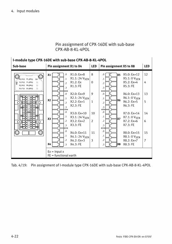
4. Input modules
4−22 Festo P.BE−CPX−EA−EN en 0705f
Pin assignment of CPX−16DE with sub−base CPX−AB−8−KL−4POL
I−module type CPX−16DE with sub−base CPX−AB−8−KL−4POL
Sub−base Pin assignment X1 to X4 LED Pin assignment X5 to X8 LED
X1
X2
X3
X4
X5
X6
X7
X8
.0
.1
.2
.3
.0
.1
.2
.3
.0
.1
.2
.3
.0
.1
.2
.3
0
1
2
3
16DI
4
5
6
7
�8
�9
10
11
12
13
14
15
X1
X2
X3
X4
.0
.1
.2
.3
.0
.1
.2
.3
.0
.1
.2
.3
.0
.1
.2
.3
X1.0: Ex+8X1.1: 24 VSENX1.2: ExX1.3: FE
X2.0: Ex+9X2.1: 24 VSENX2.2: Ex+1X2.3: FE
X3.0: Ex+10X3.1: 24 VSENX3.2: Ex+2X3.3: FE
X4.0: Ex+11X4.1: 24 VSENX4.2: Ex+3X4.3: FE
8
0
9
1
10
2
11
3
X5
X6
X7
X8
.0
.1
.2
.3
.0
.1
.2
.3
.0
.1
.2
.3
.0
.1
.2
.3
X5.0: Ex+12X5.1: 0 VSENX5.2: Ex+4X5.3: FE
X6.0: Ex+13X6.1: 0 VSENX6.2: Ex+5X6.3: FE
X7.0: Ex+14X7.1: 0 VSENX7.2: Ex+6X7.3: FE
X8.0: Ex+15X8.1: 0 VSENX8.2: Ex+7X8.3: FE
12
4
13
5
14
6
15
7
Ex = Input xFE = functional earth
Tab.�4/19: Pin assignment of I−module type CPX−16DE with sub−base CPX−AB−8−KL−4POL
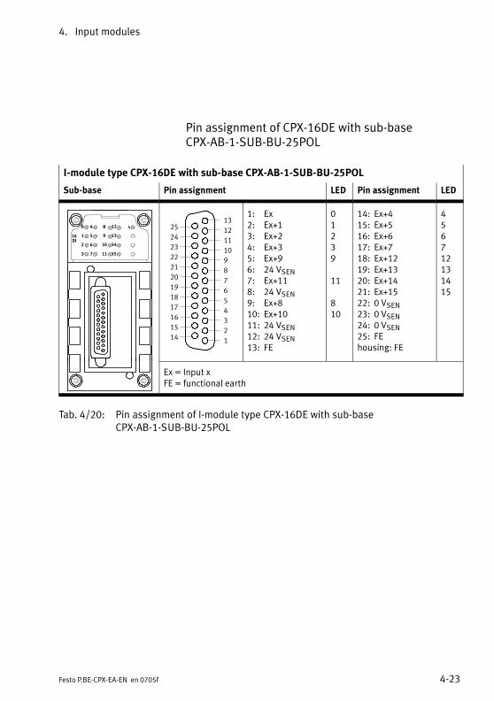
4. Input modules
4−23Festo P.BE−CPX−EA−EN en 0705f
Pin assignment of CPX−16DE with sub−base CPX−AB−1−SUB−BU−25POL
I−module type CPX−16DE with sub−base CPX−AB−1−SUB−BU−25POL
Sub−base Pin assignment LED Pin assignment LED
0
1
2
3
16DI
4
5
6
7
�8
�9
10
11
12
13
14
15
1
2
3
4
5
6
7
8
9
10
11
12
13
14
15
16
17
18
19
20
21
22
23
24
25
1: Ex2: Ex+13: Ex+24: Ex+35: Ex+96: 24 VSEN7: Ex+118: 24 VSEN9: Ex+810: Ex+1011: 24 VSEN12: 24 VSEN13: FE
01239
11
810
14: Ex+415: Ex+516: Ex+617: Ex+718: Ex+1219: Ex+1320: Ex+1421: Ex+1522: 0 VSEN23: 0 VSEN24: 0 VSEN25: FEhousing: FE
456712131415
Ex = Input xFE = functional earth
Tab.�4/20: Pin assignment of I−module type CPX−16DE with sub−baseCPX−AB−1−SUB−BU−25POL

4. Input modules
4−24 Festo P.BE−CPX−EA−EN en 0705f
4.3.5 Input module CPX−16DE−D
Pin assignment of CPX−16DE−D with sub−base CPX−M−8−M12x2−5POL
I module type CPX−M−16DE−D with sub−base CPX−AB−8−M12x2−5POL
Sub−base Pin assignment X1, X2, X3, X4 LED Pin assignment X5, X6, X7, X8 LED
2
3
1
5
4 X2
2
3
1
5
4
2
3
1
5
4
2
3
1
5
4 X4
X3
X1
Socket X1:1: 24 VSENx2: Ex+13: 0 VSENx4: Ex5: FE1)
Socket X2:1: 24 VSENx+22: Ex+33: 0 VSENx+24: Ex+25: FE1)
Socket X3:1: 24 VSENx+42: Ex+53: 0 VSENx+44: Ex+45: FE1)
Socket X4:1: 24 VSENx+62: EX+73: 0 VSENx+64: Ex+65: FE1)
1
0
3
2
5
4
7
6
2
3
1
5
4
2
3
1
5
4
2
3
1
5
4
X5
2
3
1
5
4
X6
X7
X8
Socket X5:1: 24 VSENx+82: Ex+93: 0 VSENx+84: Ex+85: FE1)
Socket X6:1: 24 VSENx+102: EX+113: 0 VSENx+104: Ex+105: FE1)
Socket X71: 24 VSENx+122: Ex+133: 0 VSENx+124: Ex+125: FE1)
Socket X8:1: 24 VSENx+142: EX+153: 0 VSENx+144: Ex+145: FE1)
9
8
11
10
13
12
15
14
Ex = Input xFE = functional earth1) With CPX−M−8−M12x2−5POL the metal thread is connected to FE
Tab.�4/21: Pin assignment of I−module type CPX−16DE−D with sub−baseCPX−M−8−M12x2−5POL
4. Input modules
4−25Festo P.BE−CPX−EA−EN en 0705f
With this sub−base the sensor supplies are available in pairs for the inputs Ex/Ex+1, Ex+2/Ex+3, .... The diagnosticmessages are displayed channel−by−channel for the inputsEx, Ex+1, Ex+2, ...
Recommendation for the 16−input module:Use the Festo DUO cable in order to connect two sensors withone plug at low cost.
CPX−M−8−M12x2−5POL The metal thread of this sub−base is connected internallywith pin�5 (functional earth FE).

4. Input modules
4−26 Festo P.BE−CPX−EA−EN en 0705f
4.3.6 Input module CPX−8NDE
Pin assignment of CPX−8NDE with sub−base CPX−AB−4−M12x2−5POL (−R), CPX−M−4−M12x2−5POL
I−module type CPX−8NDE with sub−base CPX−AB−4−M12x2−5POL (−R), CPX−M−4−M12x2−5POL
Sub−base Pin assignment X1, X2 LED Pin assignment X3, X4 LED
0
1
2
3
8NDI
4
5
6
7 2
2
3
3
1
1
5
5
4
4
X1
X2
Socket X1:1: 24 VSEN2: Ex+13: 0 VSEN4: Ex5: FE1)
Socket X2:1: 24 VSEN2: Ex+33: 0 VSEN4: Ex+25: FE1)
1
0
3
2
2
2
3
3
1
1
5
5
4
4
X3
X4
Socket X31: 24 VSEN2: Ex+53: 0 VSEN4: Ex+45: FE1)
Socket X4:1: 24 VSEN2: EX+73: 0 VSEN4: Ex+65: FE1)
5
4
7
6
*) example ofrepresentation withCPX−AB−4−M12x2−5POL
Ex = Input xFE = functional earth1) With CPX−AB−4−M12x2−5POL−R and CPX−M−4−M12x2−5POL the metal
thread is connected to FE
Tab.�4/22: Pin assignment of I−module type CPX−8NDE with sub−baseCPX−AB−4−M12x2−5POL (−R), CPX−M−4−M12x2−5POL
Recommendation for the 8−input module:Use the Festo DUO cable in order to connect two sensors withone plug at low cost.
CPX−AB−4−M12x2−5POL−R,CPX−M−4−M12x2−5POL
The metal thread of these sub−bases is connected internallywith pin�5 (functional earth FE).
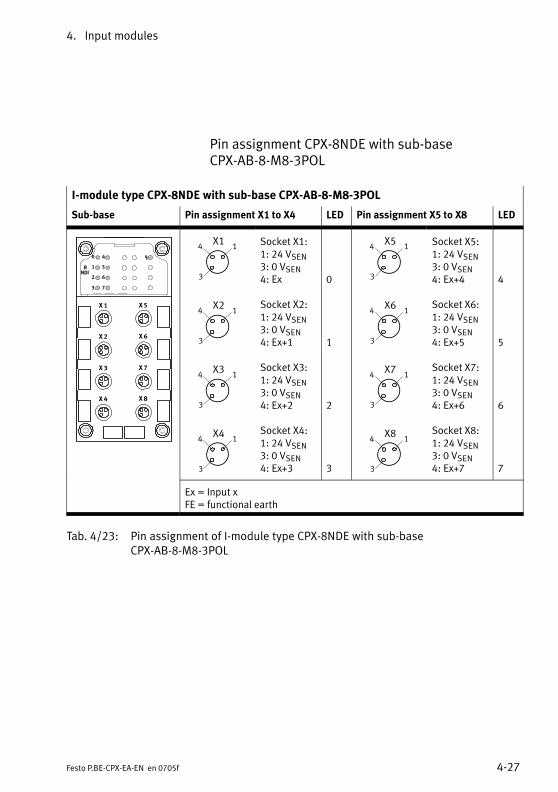
4. Input modules
4−27Festo P.BE−CPX−EA−EN en 0705f
Pin assignment CPX−8NDE with sub−base CPX−AB−8−M8−3POL
I−module type CPX−8NDE with sub−base CPX−AB−8−M8−3POL
Sub−base Pin assignment X1 to X4 LED Pin assignment X5 to X8 LED
X�1
X�2
X�3
X�4
X�5
X�6
X�7
X�8
0
1
2
3
8NDI
4
5
6
7
X14 1
3
X24 1
3
X34 1
3
X44 1
3
Socket X1:1: 24 VSEN3: 0 VSEN4: Ex
Socket X2:1: 24 VSEN3: 0 VSEN4: Ex+1
Socket X3:1: 24 VSEN3: 0 VSEN4: Ex+2
Socket X4:1: 24 VSEN3: 0 VSEN4: Ex+3
0
1
2
3
X54 1
3
X64 1
3
X74 1
3
X84 1
3
Socket X5:1: 24 VSEN3: 0 VSEN4: Ex+4
Socket X6:1: 24 VSEN3: 0 VSEN4: Ex+5
Socket X7:1: 24 VSEN3: 0 VSEN4: Ex+6
Socket X8:1: 24 VSEN3: 0 VSEN4: Ex+7
4
5
6
7
Ex = Input xFE = functional earth
Tab.�4/23: Pin assignment of I−module type CPX−8NDE with sub−base CPX−AB−8−M8−3POL

4. Input modules
4−28 Festo P.BE−CPX−EA−EN en 0705f
Pin assignment of CPX−8NDE with sub−base CPX−AB−8−KL−4POL
I−module type CPX−8NDE with sub−base CPX−AB−8−KL−4POL
Sub−base Pin assignment X1 to X4 LED Pin assignment X5 to X8 LED
X1
X2
X3
X4
X5
X6
X7
X8
.0
.1
.2
.3
.0
.1
.2
.3
.0
.1
.2
.3
.0
.1
.2
.3
0
1
2
3
8NDI
4
5
6
7
X1
X2
X3
X4
.0
.1
.2
.3
.0
.1
.2
.3
.0
.1
.2
.3
.0
.1
.2
.3
X1.0: 24 VSENX1.1: 0 VSENX1.2: ExX1.3: FE
X2.0: 24 VSENX2.1: 0 VSENX2.2: Ex+1X2.3: FE
X3.0: 24 VSENX3.1: 0 VSENX3.2: Ex+2X3.3: FE
X4.0: 24 VSENX4.1: 0 VSENX4.2: Ex+3X4.3: FE
0
1
2
3
X5
X6
X7
X8
.0
.1
.2
.3
.0
.1
.2
.3
.0
.1
.2
.3
.0
.1
.2
.3
X5.0: 24 VSENX5.1: 0 VSENX5.2: Ex+4X5.3: FE
X6.0: 24 VSENX6.1: 0 VSENX6.2: Ex+5X6.3: FE
X7.0: 24 VSENX7.1: 0 VSENX7.2: Ex+6X7.3: FE
X8.0: 24 VSENX8.1: 0 VSENX8.2: Ex+7X8.3: FE
4
5
6
7
Ex = Input xFE = functional earth
Tab.�4/24: Pin assignment of I−module type CPX−8NDE with sub−base CPX−AB−8−KL−4POL
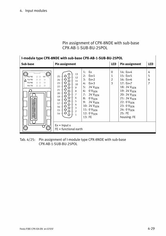
4. Input modules
4−29Festo P.BE−CPX−EA−EN en 0705f
Pin assignment of CPX−8NDE with sub−base CPX−AB−1−SUB−BU−25POL
I−module type CPX−8NDE with sub−base CPX−AB−1−SUB−BU−25POL
Sub−base Pin assignment LED Pin assignment LED
0
1
2
3
8NDI
4
5
6
7
1
2
3
4
5
6
7
8
9
10
11
12
13
14
15
16
17
18
19
20
21
22
23
24
25
1: Ex2: Ex+13: Ex+24: Ex+35: 24 VSEN6: 0 VSEN7: 24 VSEN8: 0 VSEN9: 24 VSEN10: 24 VSEN11: 0 VSEN12: 0 VSEN13: FE
0123
14: Ex+415: Ex+516: Ex+617: Ex+718: 24 VSEN19: 24 VSEN20: 24 VSEN21: 24 VSEN22: 0 VSEN23: 0 VSEN24: 0 VSEN25: FEhousing: FE
4567
Ex = Input xFE = functional earth
Tab.�4/25: Pin assignment of I−module type CPX−8NDE with sub−baseCPX−AB−1−SUB−BU−25POL

4. Input modules
4−30 Festo P.BE−CPX−EA−EN en 0705f
Pin assignment of CPX−8NDE with sub−base CPX−AB−4−HARX2−4POL
I−module type CPX−8NDE with sub−base CPX−AB−2−HARX2−4POL
Sub−base Pin assignment X1, X2 LED Pin assignment X3, X4 LED
0
1
2
3
8NDI
4
5
6
7
23
14
X1
X22 3
1 4
Socket X1:1: 24 VSEN2: Ex+13: 0 VSEN4: Ex
Socket X2:1: 24 VSEN2: Ex+33: 0 VSEN4: Ex+2
1
0
3
2
23
14
X3
X42 3
1 4
Socket X31: 24 VSEN2: Ex+53: 0 VSEN4: Ex+4
Socket X4:1: 24 VSEN2: EX+73: 0 VSEN4: Ex+6
5
4
7
6
Ex = Input xFE = functional earth
Tab.�4/26: Pin assignment of I−module type CPX−8NDE with sub−base CPX−AB−4−HARX2−4POL
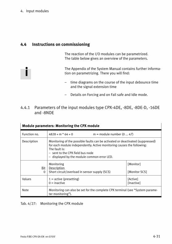
4. Input modules
4−31Festo P.BE−CPX−EA−EN en 0705f
4.4 Instructions on commissioning
The reaction of the I/O modules can be parametrized. The table below gives an overview of the parameters.
The Appendix of the System Manual contains further informa�tion on parametrizing. There you will find:
� time diagrams on the course of the input debounce timeand the signal extension time
� Details on Forcing and on Fail safe and Idle mode.
4.4.1 Parameters of the input modules type CPX−4DE, −8DE, −8DE−D, −16DEand −8NDE
Module parameters: Monitoring the CPX module
Function no. 4828 + m * 64 + 0 m = module number (0 ... 47)
Description Monitoring of the possible faults can be activated or deactivated (suppressed)for each module independently. Active monitoring causes the following: The fault is:� sent to the CPX field bus node� displayed by the module common error LED.
Bit0
MonitoringDescription Short circuit/overload in sensor supply (SCS)
[Monitor]
[Monitor SCS]
Values 1 = active (presetting)0 = inactive
[Active][Inactive]
Note Monitoring can also be set for the complete CPX terminal (see �System parame�ter monitoring").
Tab.�4/27: Monitoring the CPX module

4. Input modules
4−32 Festo P.BE−CPX−EA−EN en 0705f
Module parameters: Reaction after short circuit/overload
Function no. 4828 + m * 64 + 1 m = module number (0 ... 47)
Description Determines after a short circuit in the sensor supply whether the power is toremain switched off or whether it is to be switched on again automatically.
Bit0
Reaction after short circuit/overloadDescription Short circuit/overload in sensor supply (SCS)
[Behaviour after]
[Behaviour after SCS]
Values 0 = VSEN remains switched off1 = VSEN switch on again (presetting)
[Leave switched off ][Resume]
Note With the setting �VSEN/OUT remains switched off," Power off/on is necessary torestore the power. Check which setting is necessary for reliable operation of yoursystem.Also with modules CPX−8DE−D and CPX−16DE−D this parameter applies to thewhole module.Detailed description under �Diagnosis," Tab.�4/33.
Tab.�4/28: Reaction after short circuit/overload
Module parameters: Input debounce time
Function no. 4828 + m * 64 + 1 m = module number (0 ... 47)
Description Determines when a change of edge of the sensor signal on this module is to beaccepted as a logical input signal.
Bit Bits 4, 5
ValuesBit 5 4
0 00 11 01 1
Input debounce timeDescription 0.1 ms3 ms (presetting)10 ms20 ms
[Debounce time]
Note Input debounce times are specified in order to eliminate interfering changes ofsignal edge during switching procedures (bouncing of the input signal). Thissetting applies to all inputs of the module.Further information on this parameter can be found in the CPX system manual.
Tab.�4/29: Input debounce time

4. Input modules
4−33Festo P.BE−CPX−EA−EN en 0705f
Module parameters: Signal extension time
Function no. 4828 + m * 64 + 1 m = module number (0 ... 47)
Description Determines the signal extension time for the relevant I−module. Signal statesaccepted as logical input signals usually remain valid at least until the specifiedsignal extension time (minimum signal duration) has expired. Changes of edgewithin the extension time are ignored.
Bit Bits 6, 7
ValuesBit 7 6
0 00 11 01 1
Signal extension timeDescription 0.5 ms15 ms (presetting)50 ms100 ms
[Signal extension]
Note There is a danger that short signals are not �recognized" due to long cycle timesof the higher−order controller. In order that such signals are also taken into con�sideration in the control sequence, a signal extension time can be specified (see section CPX system manual). The signal extension time can be activatedchannel−by−channel (see channel−specific module parameters).
Tab.�4/30: Signal extension time
Module parameters: Signal extension channel x
Function no. 4828 + m * 64 + 6 m = module number (0 ... 47)4828 + m * 64 + 7 (additionally for CPX−16DE, channel 8 ... 15)
Description Determines whether the signal extension for the relevant I−channel is to be ena�bled or blocked.
Bit Bit 0 ... 7 (channel 0 ... 7)Bit 0 ... 7 (channel 8 ... 15) (for CPX−16DE channel 8 ... 15
with function no. 4828 + m * 64 + 7)
Values Signal extension input channel ...0 = blocked (presetting)1 = enabled
[Signal extension Inp Ch ...][Disabled][Enabled]
Note The signal extension time can be specified separately for each module (see function no. 4828 + m * 64 +1, bit 6, 7).
Tab.�4/31: Signal extension channel x (channel−specific)
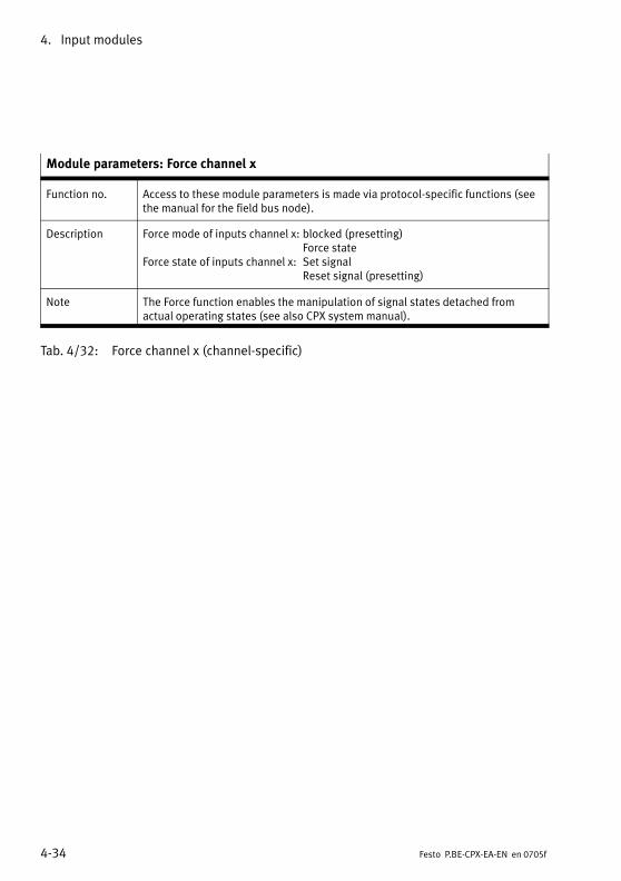
4. Input modules
4−34 Festo P.BE−CPX−EA−EN en 0705f
Module parameters: Force channel x
Function no. Access to these module parameters is made via protocol−specific functions (seethe manual for the field bus node).
Description Force mode of inputs channel x: blocked (presetting)Force state
Force state of inputs channel x: Set signalReset signal (presetting)
Note The Force function enables the manipulation of signal states detached fromactual operating states (see also CPX system manual).
Tab.�4/32: Force channel x (channel−specific)
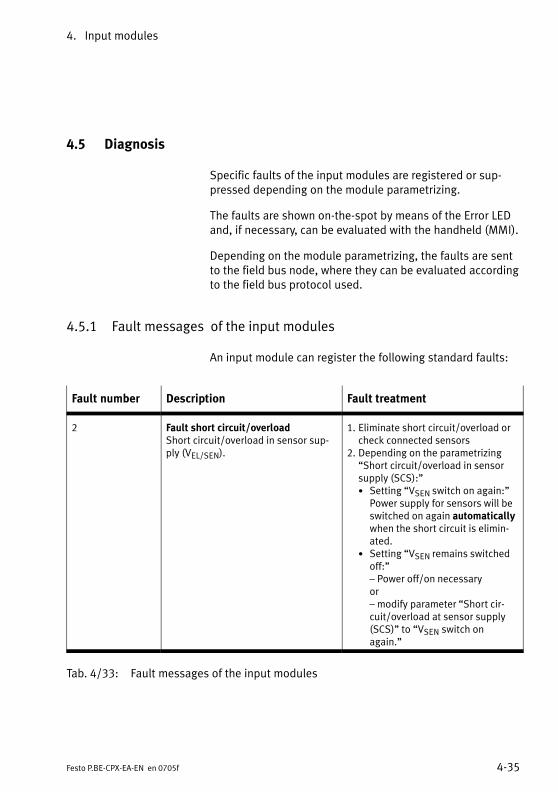
4. Input modules
4−35Festo P.BE−CPX−EA−EN en 0705f
4.5 Diagnosis
Specific faults of the input modules are registered or sup�pressed depending on the module parametrizing.
The faults are shown on−the−spot by means of the Error LEDand, if necessary, can be evaluated with the handheld (MMI).
Depending on the module parametrizing, the faults are sentto the field bus node, where they can be evaluated accordingto the field bus protocol used.
4.5.1 Fault messages of the input modules
An input module can register the following standard faults:
Fault number Description Fault treatment
2 Fault short circuit/overloadShort circuit/overload in sensor sup�ply (VEL/SEN).
1. Eliminate short circuit/overload orcheck connected sensors
2. Depending on the parametrizing�Short circuit/overload in sensorsupply (SCS):"· Setting �VSEN switch on again:"
Power supply for sensors will beswitched on again automaticallywhen the short circuit is elimin�ated.
· Setting �VSEN remains switchedoff:"� Power off/on necessaryor� modify parameter �Short cir�cuit/overload at sensor supply(SCS)" to �VSEN switch onagain."
Tab.�4/33: Fault messages of the input modules

4. Input modules
4−36 Festo P.BE−CPX−EA−EN en 0705f
NotePlease note the following when using the input modules:
� CPX−4DE, CPX−8DE, CPX−16DE and CPX−8NDE: If there isa short circuit, all sensor supplies of the module will beswitched off together.
� CPX−8DE−D: If there is a short circuit, all sensor suppliesof the module will be switched off channel−by−channel.Exception with sub−bases AB−4−M12x2−5POL(−R),AB−4−HARX2−4POL and CPX−M−4−M12x2−5POL:The sensor supplies are grouped together in pairs withthese sub−bases. The following are switched off to�gether: Ex and Ex+1, Ex+2 and Ex+3, ...The diagnostic messages are therefore only for the in�puts Ex, Ex+2, Ex+4 and Ex+6. The inputs Ex+1, Ex+3,Ex+5 and Ex+7 do not generate a diagnostic message.
� CPX−16DE−D: If there is a short circuit, all sensor sup�plies of the module will be switched off in pairs. Ex andEx+1, Ex+2 and Ex+3, ...The diagnostic meassages are displayed channel−by−channel for the inputs Ex, Ex+1, Ex+2, ...
� Providing it is not programmed otherwise, the sensorsupply voltage will be switched on again automaticallywhen the short circuit is eliminated.
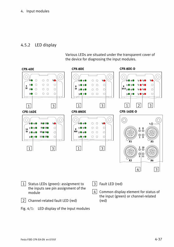
4. Input modules
4−37Festo P.BE−CPX−EA−EN en 0705f
4.5.2 LED display
Various LEDs are situated under the transparent cover of the device for diagnosing the input modules.
0
1
2
3
8DI
4
5
6
7
CPX−8DE CPX−8DE−D
0
1
2
3
8DI−D
4
5
6
7
0
1
2
3
4DI
CPX−4DE
1 23 11 3 3
0
1
2
3
8NDI
4
5
6
7
CPX−8NDE
1 3
0
1
2
3
16DI
4
5
6
7
CPX−16DE
1 3
8
9
10
11
12
13
14
15
4 3
CPX−16DE−D
1 Status LEDs (green): assignment to the inputs see pin assignment of themodule
2 Channel−related fault LED (red)
3 Fault LED (red)
4 Common display element for status ofthe input (green) or channel−related(red)
Fig.�4/1: LED display of the input modules
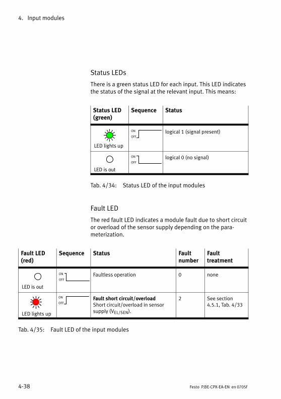
4. Input modules
4−38 Festo P.BE−CPX−EA−EN en 0705f
Status LEDs
There is a green status LED for each input. This LED indicatesthe status of the signal at the relevant input. This means:
Status LED(green)
Sequence Status
LED lights up
ON
OFF
logical 1 (signal present)
LED is out
ON
OFF
logical 0 (no signal)
Tab.�4/34: Status LED of the input modules
Fault LED
The red fault LED indicates a module fault due to short circuitor overload of the sensor supply depending on the para�meterization.
Fault LED(red)
Sequence Status Faultnumber
Fault treatment
LED is out
ON
OFF
Faultless operation 0 none
LED lights up
ON
OFFFault short circuit/overloadShort circuit/overload in sensorsupply (VEL/SEN).
2 See section4.5.1, Tab.�4/33
Tab.�4/35: Fault LED of the input modules
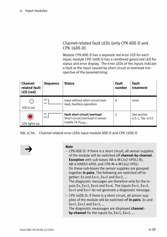
4. Input modules
4−39Festo P.BE−CPX−EA−EN en 0705f
Channel−related fault LEDs (only CPX−8DE−D andCPX−16DE−D)
Module CPX−8DE−D has a separate red error LED for eachinput; module CPX−16DE−D has a combined green/red LED forstatus and error display. The error LEDs of the inputs indicatea fault at the input caused by short circuit or overload irre�spective of the parametrizing.
Channel−related faultLED (red)
Sequence Status Faultnumber
Fault treatment
LED is out
ON
OFF
Input without short circuit/over�load, faultless operation
0 none
LED lights up
ON
OFFFault short circuit/overloadShort circuit/overload in sensorsupply 24 VSENx...
2 See section4.5.1, Tab.�4/33
Tab.�4/36: Channel−related error LEDs input module 8DE−D and CPX−16DE−D
Note� CPX−8DE−D: If there is a short circuit, all sensor suppliesof the module will be switched off channel−by−channel.Exception with sub−bases AB−4−M12x2−5POL(−R),AB−4−HARX2−4POL and CPX−M−4−M12x2−5POL:On these sub−bases the sensor supplies are groupedtogether in pairs. The following are switched off to�gether: Ex and Ex+1, Ex+2 and Ex+3, ...The diagnostic messages are therefore only for the in�puts Ex, Ex+2, Ex+4 and Ex+6. The inputs Ex+1, Ex+3,Ex+5 and Ex+7 do not generate a diagnostic message.
� CPX−16DE−D: If there is a short circuit, all sensor sup�plies of the module will be switched off in pairs. Ex andEx+1, Ex+2 and Ex+3, ...The diagnostic meassages are displayed channel−by−channel for the inputs Ex, Ex+1, Ex+2, ...

4. Input modules
4−40 Festo P.BE−CPX−EA−EN en 0705f
4.5.3 Fault treatment and parametrizing
The following diagram shows the fault treatment of the inputmodules. With the appropriate module parameter, repre�sented in the diagram as a switch, further registering anddisplay of the fault can be suppressed as desired. A descrip�tion of the parameter can be found in section 4.4.
Fault no. 2
Short circuit/overload insensor supply
Error message to the field bus node
Monitoring SCS
Module faultLED
2
1
0 1
1 Module parameters(switch position represented = default setting)
2 Module−specific faults
Fig.�4/2: Principle of fault treatment and parametrizing ofthe input modules
Output modules
5−1Festo P.BE−CPX−EA−EN en 0705f
Chapter 5
Type CPX−4DA
CPX−8DA
CPX−8DA−H

5. Output modules
5−2 Festo P.BE−CPX−EA−EN en 0705f
Contents
5. Output modules 5−1 . . . . . . . . . . . . . . . . . . . . . . . . . . . . . . . . . . . . . . . . . . . . . . . .
5.1 Function of the output modules 5−3 . . . . . . . . . . . . . . . . . . . . . . . . . . . . . . . . . . .
5.2 Mounting 5−3 . . . . . . . . . . . . . . . . . . . . . . . . . . . . . . . . . . . . . . . . . . . . . . . . . . . . . .
5.3 Installation 5−4 . . . . . . . . . . . . . . . . . . . . . . . . . . . . . . . . . . . . . . . . . . . . . . . . . . . .
5.3.1 Output module CPX−4DA 5−5 . . . . . . . . . . . . . . . . . . . . . . . . . . . . . . . . . .
5.3.2 Output module CPX−8DA 5−11 . . . . . . . . . . . . . . . . . . . . . . . . . . . . . . . . . .
5.3.3 High−current output module CPX−8DA−H 5−17 . . . . . . . . . . . . . . . . . . . . .
5.4 Instructions on commissioning 5−22 . . . . . . . . . . . . . . . . . . . . . . . . . . . . . . . . . . . .
5.4.1 Parameters of the output modules types CPX−4DA, CPX−8DA andCPX−8DA−H 5−22 . . . . . . . . . . . . . . . . . . . . . . . . . . . . . . . . . . . . . . . . . . . . .
5.5 Diagnosis 5−25 . . . . . . . . . . . . . . . . . . . . . . . . . . . . . . . . . . . . . . . . . . . . . . . . . . . . .
5.5.1 Error messages of the output modules 5−26 . . . . . . . . . . . . . . . . . . . . . .
5.5.2 LED display 5−28 . . . . . . . . . . . . . . . . . . . . . . . . . . . . . . . . . . . . . . . . . . . .
5.5.3 Fault treatment and parametrizing 5−30 . . . . . . . . . . . . . . . . . . . . . . . . . .

5. Output modules
5−3Festo P.BE−CPX−EA−EN en 0705f
5.1 Function of the output modules
Output modules provide digital outputs for connecting electric actuators and other current−consuming devices(valves, contactors, displays) in the valve terminal. At presentthe following type is available:
Type Description
CPX−4DA Provides 4 digital outputs(based on IEC�1131 type 2, 24�V,positive logic � PNP).
CPX−8DA Provides 8 digital outputs (as per IEC�1131 type 2, 24�V,positive logic � PNP).
CPX−8DA−H Provides 8 digital outputs(based on IEC�1131 type 2, 24�V,positive logic � PNP).
Tab.�5/1: Overview of output modules
5.2 Mounting
See section 3.3.
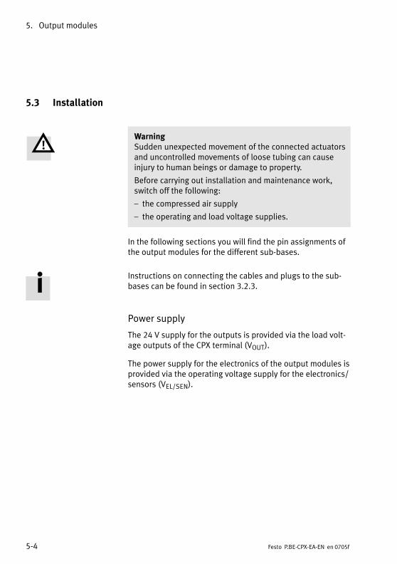
5. Output modules
5−4 Festo P.BE−CPX−EA−EN en 0705f
5.3 Installation
WarningSudden unexpected movement of the connected actuatorsand uncontrolled movements of loose tubing can causeinjury to human beings or damage to property.
Before carrying out installation and maintenance work,switch off the following:
� the compressed air supply
� the operating and load voltage supplies.
In the following sections you will find the pin assignments ofthe output modules for the different sub−bases.
Instructions on connecting the cables and plugs to the sub−bases can be found in section 3.2.3.
Power supply
The 24 V supply for the outputs is provided via the load volt�age outputs of the CPX terminal (VOUT).
The power supply for the electronics of the output modules isprovided via the operating voltage supply for the electronics/sensors (VEL/SEN).

5. Output modules
5−5Festo P.BE−CPX−EA−EN en 0705f
5.3.1 Output module CPX−4DA
Pin assignment CPX−4DA with sub−base CPX−AB−4−M12x2−5POL (−R), CPX−M−4−M12x2−5POL
O−module type CPX−4DA with sub−base CPX−AB−4−M12x2−5POL (−R), CPX−M−4−M12x2−5POL
Sub−base Pin assignment X1, X2 LED Pin assignment X3, X4 LED
0
1
2
3
4DO
1
2
2
3
3
1
1
5
5
4
4
X1
X2
Socket X1:1: n.c.2: Ax+13: 0 VOUT4: Ax5: FE1)
Socket X2:1: n.c.2: n.c.3: 0 VOUT4: Ax+15: FE1)
1
0
1
1
2
2
3
3
1
1
5
5
4
4
X3
X4
Socket X31: n.c.2: Ax+33: 0 VOUT4: Ax+25: FE1)
Socket X4:1: n.c.2: n.c.3: 0 VOUT4: Ax+35: FE1)
3
2
3
*) example ofrepresentation withCPX−AB−4−M12x2−5POL
Ax = Output xFE = functional earthn.c. = not connected
1 connected internally1) With CPX−AB−4−M12x2−5POL−R and CPX−M−4−M12x2−5POL the metal
thread is connected to FE
Tab.�5/2: Pin assignment of O−module type CPX−4DA with sub−basesCPX−AB−4−M12x2−5POL (−R), CPX−M−4−M12x2−5POL
CPX−AB−4−M12x2−5POL−R,CPX−M−4−M12x2−5POL
The metal thread of these sub−bases is connected internallywith pin�5 (functional earth FE).
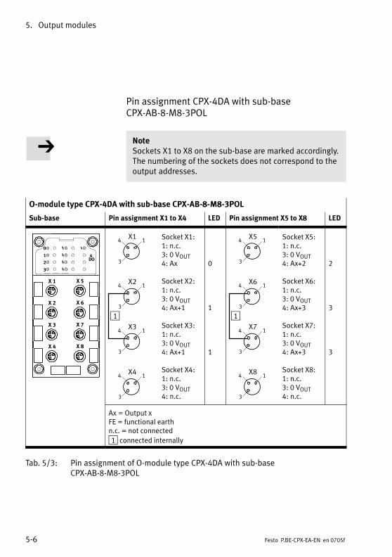
5. Output modules
5−6 Festo P.BE−CPX−EA−EN en 0705f
Pin assignment CPX−4DA with sub−base CPX−AB−8−M8−3POL
NoteSockets X1 to X8 on the sub−base are marked accordingly.The numbering of the sockets does not correspond to theoutput addresses.
O−module type CPX−4DA with sub−base CPX−AB−8−M8−3POL
Sub−base Pin assignment X1 to X4 LED Pin assignment X5 to X8 LED
0
1
2
3
4DO
X�1
X�2
X�3
X�4
X�5
X�6
X�7
X�8
1
X14 1
3
X24 1
3
X34 1
3
X44 1
3
Socket X1:1: n.c.3: 0 VOUT4: Ax
Socket X2:1: n.c.3: 0 VOUT4: Ax+1
Socket X3:1: n.c.3: 0 VOUT4: Ax+1
Socket X4:1: n.c.3: 0 VOUT4: n.c.
0
1
1
1
X54 1
3
X64 1
3
X74 1
3
X84 1
3
Socket X5:1: n.c.3: 0 VOUT4: Ax+2
Socket X6:1: n.c.3: 0 VOUT4: Ax+3
Socket X7:1: n.c.3: 0 VOUT4: Ax+3
Socket X8:1: n.c.3: 0 VOUT4: n.c.
2
3
3
Ax = Output xFE = functional earthn.c. = not connected
1 connected internally
Tab.�5/3: Pin assignment of O−module type CPX−4DA with sub−baseCPX−AB−8−M8−3POL
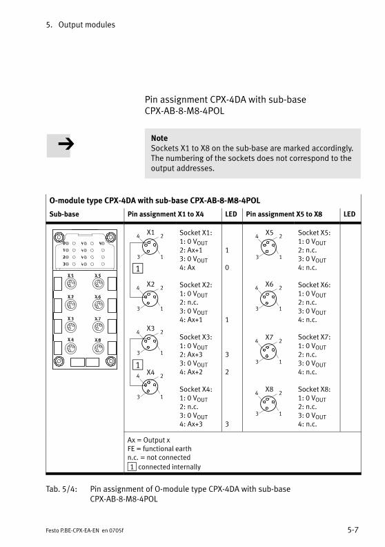
5. Output modules
5−7Festo P.BE−CPX−EA−EN en 0705f
Pin assignment CPX−4DA with sub−base CPX−AB−8−M8−4POL
NoteSockets X1 to X8 on the sub−base are marked accordingly.The numbering of the sockets does not correspond to theoutput addresses.
O−module type CPX−4DA with sub−base CPX−AB−8−M8−4POL
Sub−base Pin assignment X1 to X4 LED Pin assignment X5 to X8 LED
X34 2
3 1
X24 2
3 1
X44 2
3 1
X14 2
3 1
1
1
Socket X1:1: 0 VOUT2: Ax+13: 0 VOUT4: Ax
Socket X2:1: 0 VOUT2: n.c.3: 0 VOUT4: Ax+1
Socket X3:1: 0 VOUT2: Ax+33: 0 VOUT4: Ax+2
Socket X4:1: 0 VOUT2: n.c.3: 0 VOUT4: Ax+3
1
0
1
3
2
3
X54 2
3 1
X64 2
3 1
X74 2
3 1
X84 2
3 1
Socket X5:1: 0 VOUT2: n.c.3: 0 VOUT4: n.c.
Socket X6:1: 0 VOUT2: n.c.3: 0 VOUT4: n.c.
Socket X7:1: 0 VOUT2: n.c.3: 0 VOUT4: n.c.
Socket X8:1: 0 VOUT2: n.c.3: 0 VOUT4: n.c.
Ax = Output xFE = functional earthn.c. = not connected
1 connected internally
Tab.�5/4: Pin assignment of O−module type CPX−4DA with sub−baseCPX−AB−8−M8−4POL
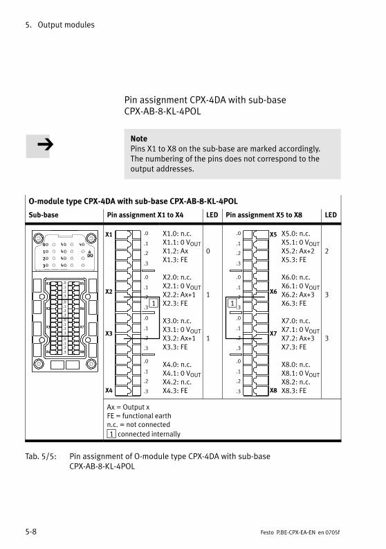
5. Output modules
5−8 Festo P.BE−CPX−EA−EN en 0705f
Pin assignment CPX−4DA with sub−base CPX−AB−8−KL−4POL
NotePins X1 to X8 on the sub−base are marked accordingly. The numbering of the pins does not correspond to theoutput addresses.
O−module type CPX−4DA with sub−base CPX−AB−8−KL−4POL
Sub−base Pin assignment X1 to X4 LED Pin assignment X5 to X8 LED
0
1
2
3
4DO
X1
X2
X3
X4
X5
X6
X7
X8
.0
.1
.2
.3
.0
.1
.2
.3
.0
.1
.2
.3
.0
.1
.2
.3
X1
X2
X3
X4
.0
.1
.2
.3
.0
.1
.2
.3
.0
.1
.2
.3
.0
.1
.2
.3
1
X1.0: n.c.X1.1: 0 VOUTX1.2: AxX1.3: FE
X2.0: n.c.X2.1: 0 VOUTX2.2: Ax+1X2.3: FE
X3.0: n.c.X3.1: 0 VOUTX3.2: Ax+1X3.3: FE
X4.0: n.c.X4.1: 0 VOUTX4.2: n.c.X4.3: FE
0
1
1
X5
X6
X7
X8
.0
.1
.2
.3
.0
.1
.2
.3
.0
.1
.2
.3
.0
.1
.2
.3
1
X5.0: n.c.X5.1: 0 VOUTX5.2: Ax+2X5.3: FE
X6.0: n.c.X6.1: 0 VOUTX6.2: Ax+3X6.3: FE
X7.0: n.c.X7.1: 0 VOUTX7.2: Ax+3X7.3: FE
X8.0: n.c.X8.1: 0 VOUTX8.2: n.c.X8.3: FE
2
3
3
Ax = Output xFE = functional earthn.c. = not connected
1 connected internally
Tab.�5/5: Pin assignment of O−module type CPX−4DA with sub−baseCPX−AB−8−KL−4POL
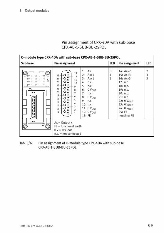
5. Output modules
5−9Festo P.BE−CPX−EA−EN en 0705f
Pin assignment of CPX−4DA with sub−base CPX−AB−1−SUB−BU−25POL
O−module type CPX−4DA with sub−base CPX−AB−1−SUB−BU−25POL
Sub−base Pin assignment LED Pin assignment LED
0
1
2
3
4DO
1
2
3
4
5
6
7
8
9
10
11
12
13
14
15
16
17
18
19
20
21
22
23
24
25
1: Ax2: Ax+13: Ax+14: n.c.5: n.c.6: 0 VOUT7: n.c.8: 0 VOUT9: n.c.10: n.c.11: 0 VOUT12: 0 VOUT13: FE
011
14: Ax+215: Ax+316: Ax+317: n.c.18: n.c.19: n.c.20: n.c.21: n.c.22: 0 VOUT23: 0 VOUT24: 0 VOUT25: FEhousing: FE
233
Ax = Output xFE = functional earth0 V = 0 V loadn.c. = not connected
Tab.�5/6: Pin assignment of O−module type CPX−4DA with sub−baseCPX−AB−1−SUB−BU−25POL
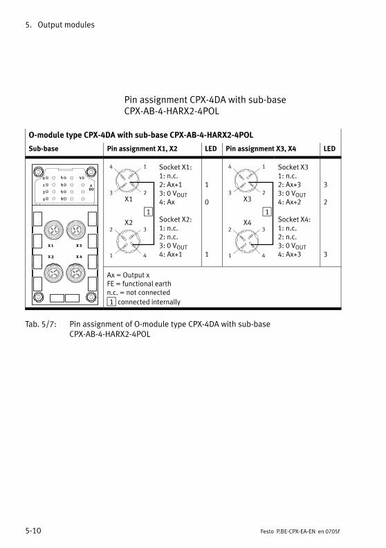
5. Output modules
5−10 Festo P.BE−CPX−EA−EN en 0705f
Pin assignment CPX−4DA with sub−base CPX−AB−4−HARX2−4POL
O−module type CPX−4DA with sub−base CPX−AB−4−HARX2−4POL
Sub−base Pin assignment X1, X2 LED Pin assignment X3, X4 LED
0
1
2
3
4DO
1
23
14
X1
X22 3
1 4
Socket X1:1: n.c.2: Ax+13: 0 VOUT4: Ax
Socket X2:1: n.c.2: n.c.3: 0 VOUT4: Ax+1
1
0
1
1
23
14
X3
X42 3
1 4
Socket X31: n.c.2: Ax+33: 0 VOUT4: Ax+2
Socket X4:1: n.c.2: n.c.3: 0 VOUT4: Ax+3
3
2
3
Ax = Output xFE = functional earthn.c. = not connected
1 connected internally
Tab.�5/7: Pin assignment of O−module type CPX−4DA with sub−base CPX−AB−4−HARX2−4POL
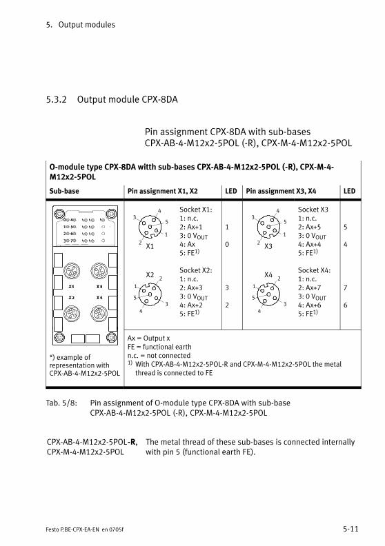
5. Output modules
5−11Festo P.BE−CPX−EA−EN en 0705f
5.3.2 Output module CPX−8DA
Pin assignment CPX−8DA with sub−bases CPX−AB−4−M12x2−5POL (−R), CPX−M−4−M12x2−5POL
O−module type CPX−8DA witth sub−bases CPX−AB−4−M12x2−5POL (−R), CPX−M−4−M12x2−5POL
Sub−base Pin assignment X1, X2 LED Pin assignment X3, X4 LED
2
2
3
3
1
1
5
5
4
4
X1
X2
Socket X1:1: n.c.2: Ax+13: 0 VOUT4: Ax5: FE1)
Socket X2:1: n.c.2: Ax+33: 0 VOUT4: Ax+25: FE1)
1
0
3
2
2
3
1
5
4
2
3
1
5
4
X3
X4
Socket X31: n.c.2: Ax+53: 0 VOUT4: Ax+45: FE1)
Socket X4:1: n.c.2: Ax+73: 0 VOUT4: Ax+65: FE1)
5
4
7
6
*) example ofrepresentation withCPX−AB−4−M12x2−5POL
Ax = Output xFE = functional earthn.c. = not connected1) With CPX−AB−4−M12x2−5POL−R and CPX−M−4−M12x2−5POL the metal
thread is connected to FE
Tab.�5/8: Pin assignment of O−module type CPX−8DA with sub−baseCPX−AB−4−M12x2−5POL (−R), CPX−M−4−M12x2−5POL
CPX−AB−4−M12x2−5POL−R,CPX−M−4−M12x2−5POL
The metal thread of these sub−bases is connected internallywith pin�5 (functional earth FE).

5. Output modules
5−12 Festo P.BE−CPX−EA−EN en 0705f
Pin assignment CPX−8DA with sub−base CPX−AB−8−M8−3POL
NoteSockets X1 to X8 on the sub−base are marked accordingly.The numbering of the sockets does not correspond to theoutput addresses.
O−module type CPX−8DA with sub−base CPX−AB−8−M8−3POL
Sub−base Pin assignment X1 to X4 LED Pin assignment X5 to X8 LED
X14 1
3
X24 1
3
X34 1
3
X44 1
3
Socket X1:1: n.c.3: 0 VOUT4: Ax
Socket X2:1: n.c.3: 0 VOUT4: Ax+1
Socket X3:1: n.c.3: 0 VOUT4: Ax+2
Socket X4:1: n.c.3: 0 VOUT4: Ax+3
0
1
2
3
X54 1
3
X64 1
3
X74 1
3
X84 1
3
Socket X5:1: n.c.3: 0 VOUT4: Ax+4
Socket X6:1: n.c.3: 0 VOUT4: Ax+5
Socket X7:1: n.c.3: 0 VOUT4: Ax+6
Socket X8:1: n.c.3: 0 VOUT4: Ax+7
4
5
6
7
Ax = Output xFE = functional earthn.c. = not connected
Tab.�5/9: Pin assignment of O−module type CPX−8DA with sub−base CPX−AB−8−M8−3POL
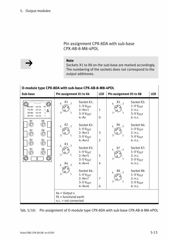
5. Output modules
5−13Festo P.BE−CPX−EA−EN en 0705f
Pin assignment CPX−8DA with sub−base CPX−AB−8−M8−4POL
NoteSockets X1 to X8 on the sub−base are marked accordingly.The numbering of the sockets does not correspond to theoutput addresses.
O−module type CPX−8DA with sub−base CPX−AB−8−M8−4POL
Sub−base Pin assignment X1 to X4 LED Pin assignment X5 to X8 LED
X34 2
3 1
X24 2
3 1
X44 2
3 1
X14 2
3 1
Socket X1:1: 0 VOUT2: Ax+13: 0 VOUT4: Ax
Socket X2:1: 0 VOUT2: Ax+33: 0 VOUT4: Ax+2
Socket X3:1: 0 VOUT2: Ax+53: 0 VOUT4: Ax+4
Socket X4:1: 0 VOUT2: Ax+73: 0 VOUT4: Ax+6
1
0
3
2
5
4
7
6
X54 2
3 1
X64 2
3 1
X74 2
3 1
X84 2
3 1
Socket X5:1: 0 VOUT2: n.c.3: 0 VOUT4: n.c.
Socket X6:1: 0 VOUT2: n.c.3: 0 VOUT4: n.c.
Socket X7:1: 0 VOUT2: n.c.3: 0 VOUT4: n.c.
Socket X8:1: 0 VOUT2: n.c.3: 0 VOUT4: n.c.
Ax = Output xFE = functional earthn.c. = not connected
Tab.�5/10: Pin assignment of O−module type CPX−8DA with sub−base CPX−AB−8−M8−4POL
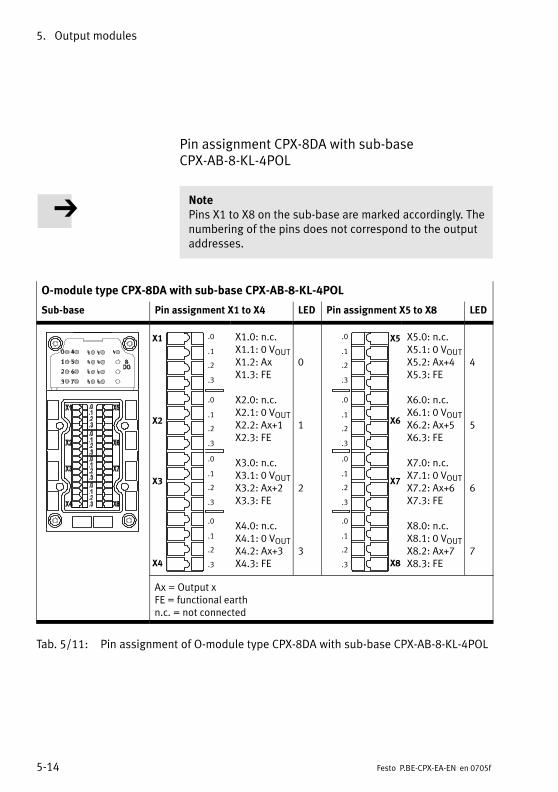
5. Output modules
5−14 Festo P.BE−CPX−EA−EN en 0705f
Pin assignment CPX−8DA with sub−base CPX−AB−8−KL−4POL
NotePins X1 to X8 on the sub−base are marked accordingly. Thenumbering of the pins does not correspond to the outputaddresses.
O−module type CPX−8DA with sub−base CPX−AB−8−KL−4POL
Sub−base Pin assignment X1 to X4 LED Pin assignment X5 to X8 LED
X1
X2
X3
X4
.0
.1
.2
.3
.0
.1
.2
.3
.0
.1
.2
.3
.0
.1
.2
.3
X1.0: n.c.X1.1: 0 VOUTX1.2: AxX1.3: FE
X2.0: n.c.X2.1: 0 VOUTX2.2: Ax+1X2.3: FE
X3.0: n.c.X3.1: 0 VOUTX3.2: Ax+2X3.3: FE
X4.0: n.c.X4.1: 0 VOUTX4.2: Ax+3X4.3: FE
0
1
2
3
X5
X6
X7
X8
.0
.1
.2
.3
.0
.1
.2
.3
.0
.1
.2
.3
.0
.1
.2
.3
X5.0: n.c.X5.1: 0 VOUTX5.2: Ax+4X5.3: FE
X6.0: n.c.X6.1: 0 VOUTX6.2: Ax+5X6.3: FE
X7.0: n.c.X7.1: 0 VOUTX7.2: Ax+6X7.3: FE
X8.0: n.c.X8.1: 0 VOUTX8.2: Ax+7X8.3: FE
4
5
6
7
Ax = Output xFE = functional earthn.c. = not connected
Tab.�5/11: Pin assignment of O−module type CPX−8DA with sub−base CPX−AB−8−KL−4POL
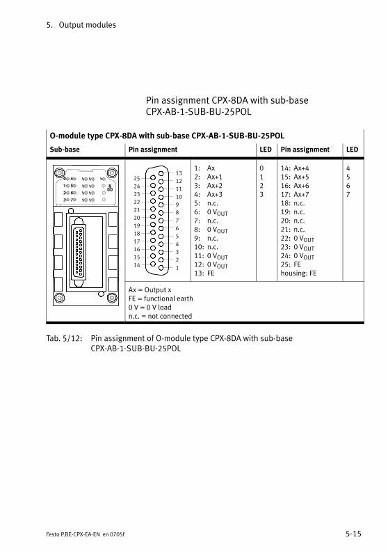
5. Output modules
5−15Festo P.BE−CPX−EA−EN en 0705f
Pin assignment CPX−8DA with sub−base CPX−AB−1−SUB−BU−25POL
O−module type CPX−8DA with sub−base CPX−AB−1−SUB−BU−25POL
Sub−base Pin assignment LED Pin assignment LED
1
2
3
4
5
6
7
8
9
10
11
12
13
14
15
16
17
18
19
20
21
22
23
24
25
1: Ax2: Ax+13: Ax+24: Ax+35: n.c.6: 0 VOUT7: n.c.8: 0 VOUT9: n.c.10: n.c.11: 0 VOUT12: 0 VOUT13: FE
0123
14: Ax+415: Ax+516: Ax+617: Ax+718: n.c.19: n.c.20: n.c.21: n.c.22: 0 VOUT23: 0 VOUT24: 0 VOUT25: FEhousing: FE
4567
Ax = Output xFE = functional earth0 V = 0 V loadn.c. = not connected
Tab.�5/12: Pin assignment of O−module type CPX−8DA with sub−baseCPX−AB−1−SUB−BU−25POL
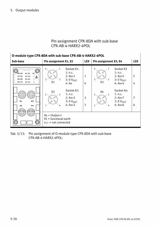
5. Output modules
5−16 Festo P.BE−CPX−EA−EN en 0705f
Pin assignment CPX−8DA with sub−base CPX−AB−4−HARX2−4POL
O−module type CPX−8DA with sub−base CPX−AB−4−HARX2−4POL
Sub−base Pin assignment X1, X2 LED Pin assignment X3, X4 LED
23
14
X1
X22 3
1 4
Socket X1:1: n.c.2: Ax+13: 0 VOUT4: Ax
Socket X2:1: n.c.2: Ax+33: 0 VOUT4: Ax+2
1
0
3
2
23
14
X3
X42 3
1 4
Socket X31: n.c.2: Ax+53: 0 VOUT4: Ax+4
Socket X4:1: n.c.2: Ax+73: 0 VOUT4: Ax+6
5
4
7
6
Ax = Output xFE = functional earthn.c. = not connected
Tab.�5/13: Pin assignment of O−module type CPX−8DA with sub−baseCPX−AB−4−HARX2−4POL:
5. Output modules
5−17Festo P.BE−CPX−EA−EN en 0705f
5.3.3 High−current output module CPX−8DA−H
The high−current output module CPX−8DA−H provides digitaloutputs in the valve terminal for connecting current−consum�ing devices with high current consumption (e.�g. hydraulicvalves).
NoteObserve the permitted characteristic connection values inthe technical specifications and the temperature de�pendency of the maximum load current as shown inFig.�A/3, in order to avoid overheating and as a result,damage to the connections and the electronic module.
Pay attention to the following when planning:
· Maximum current consumption of 2.1�A per output/chan�nel or per output socket when the plug/cable is assignedtwice and maximum current consumption of 8.4�A for thecomplete module.
· Note the instructions/footnotes for the relevant sub−base.
· Note the instructions on contact loading for the relevantsub−base.
· Use electric conductors with suitable diameter.
· Avoid long distances between the load and the high−cur�rent output.
Protection against In addition to a (reversible) electronic short circuit protectionshort circuit the output module also possesses an (irreversible) fuse (fus�
ible cutout) in case the electronic short circuit protectiondevice fails.
NoteAfter the fusible cutout has functioned, the high−currentoutput module must be replaced.
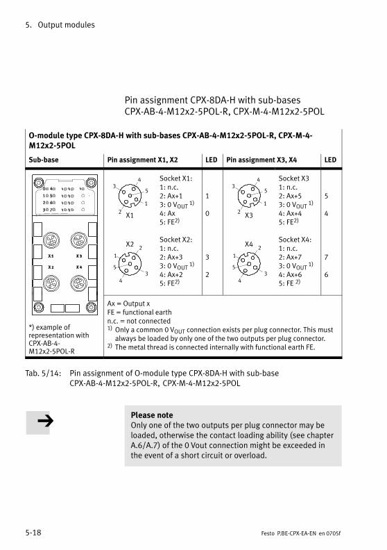
5. Output modules
5−18 Festo P.BE−CPX−EA−EN en 0705f
Pin assignment CPX−8DA−H with sub−bases CPX−AB−4−M12x2−5POL−R, CPX−M−4−M12x2−5POL
O−module type CPX−8DA−H with sub−bases CPX−AB−4−M12x2−5POL−R, CPX−M−4−M12x2−5POL
Sub−base Pin assignment X1, X2 LED Pin assignment X3, X4 LED
2
2
3
3
1
1
5
5
4
4
X1
X2
Socket X1:1: n.c.2: Ax+13: 0 VOUT 1)
4: Ax5: FE2)
Socket X2:1: n.c.2: Ax+33: 0 VOUT 1)
4: Ax+25: FE2)
1
0
3
2
2
3
1
5
4
2
3
1
5
4
X3
X4
Socket X31: n.c.2: Ax+53: 0 VOUT 1)
4: Ax+45: FE2)
Socket X4:1: n.c.2: Ax+73: 0 VOUT 1)
4: Ax+65: FE 2)
5
4
7
6
*) example ofrepresentation withCPX−AB−4−M12x2−5POL−R
Ax = Output xFE = functional earthn.c. = not connected1) Only a common 0�VOUT connection exists per plug connector. This must
always be loaded by only one of the two outputs per plug connector.2) The metal thread is connected internally with functional earth FE.
Tab.�5/14: Pin assignment of O−module type CPX−8DA−H with sub−baseCPX−AB−4−M12x2−5POL−R, CPX−M−4−M12x2−5POL
Please noteOnly one of the two outputs per plug connector may beloaded, otherwise the contact loading ability (see chapterA.6/A.7) of the 0�Vout connection might be exceeded inthe event of a short circuit or overload.
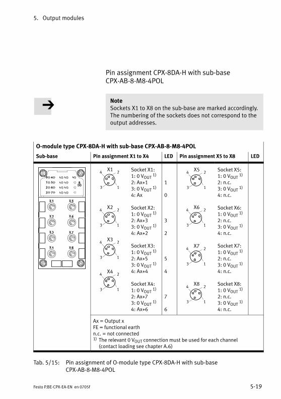
5. Output modules
5−19Festo P.BE−CPX−EA−EN en 0705f
Pin assignment CPX−8DA−H with sub−base CPX−AB−8−M8−4POL
NoteSockets X1 to X8 on the sub−base are marked accordingly.The numbering of the sockets does not correspond to theoutput addresses.
O−module type CPX−8DA−H with sub−base CPX−AB−8−M8−4POL
Sub−base Pin assignment X1 to X4 LED Pin assignment X5 to X8 LED
X34 2
3 1
X24 2
3 1
X44 2
3 1
X14 2
3 1
Socket X1:1: 0 VOUT 1)
2: Ax+13: 0 VOUT 1)
4: Ax
Socket X2:1: 0 VOUT 1)
2: Ax+33: 0 VOUT 1)
4: Ax+2
Socket X3:1: 0 VOUT 1)
2: Ax+53: 0 VOUT 1)
4: Ax+4
Socket X4:1: 0 VOUT 1)
2: Ax+73: 0 VOUT 1)
4: Ax+6
1
0
3
2
5
4
7
6
X54 2
3 1
X64 2
3 1
X74 2
3 1
X84 2
3 1
Socket X5:1: 0 VOUT 1)
2: n.c.3: 0 VOUT 1)
4: n.c.
Socket X6:1: 0 VOUT 1)
2: n.c.3: 0 VOUT 1)
4: n.c.
Socket X7:1: 0 VOUT 1)
2: n.c.3: 0 VOUT 1)
4: n.c.
Socket X8:1: 0 VOUT 1)
2: n.c.3: 0 VOUT 1)
4: n.c.
Ax = Output xFE = functional earthn.c. = not connected1) The relevant 0�VOUT connection must be used for each channel
(contact loading see chapter�A.6)
Tab.�5/15: Pin assignment of O−module type CPX−8DA−H with sub−base CPX−AB−8−M8−4POL
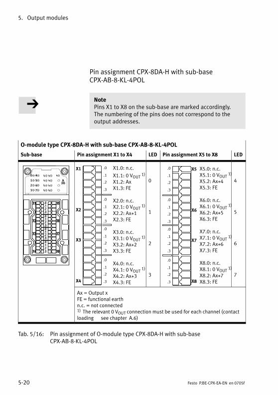
5. Output modules
5−20 Festo P.BE−CPX−EA−EN en 0705f
Pin assignment CPX−8DA−H with sub−base CPX−AB−8−KL−4POL
NotePins X1 to X8 on the sub−base are marked accordingly. The numbering of the pins does not correspond to theoutput addresses.
O−module type CPX−8DA−H with sub−base CPX−AB−8−KL−4POL
Sub−base Pin assignment X1 to X4 LED Pin assignment X5 to X8 LED
X1.0: n.c.
X1.1: 0 VOUT 1)
X1.2: AxX1.3: FE
X2.0: n.c.X2.1: 0 VOUT 1)
X2.2: Ax+1X2.3: FE
X3.0: n.c.X3.1: 0 VOUT 1)
X3.2: Ax+2X3.3: FE
X4.0: n.c.X4.1: 0 VOUT 1)
X4.2: Ax+3X4.3: FE
X1
X2
X3
X4
.0
.1
.2
.3
.0
.1
.2
.3
.0
.1
.2
.3
.0
.1
.2
.3
0
1
2
3
X5.0: n.c.X5.1: 0 VOUT 1)
X5.2: Ax+4X5.3: FE
X6.0: n.c.X6.1: 0 VOUT 1)
X6.2: Ax+5X6.3: FE
X7.0: n.c.X7.1: 0 VOUT 1)
X7.2: Ax+6X7.3: FE
X8.0: n.c.X8.1: 0 VOUT 1)
X8.2: Ax+7X8.3: FE
X5
X6
X7
X8
.0
.1
.2
.3
.0
.1
.2
.3
.0
.1
.2
.3
.0
.1
.2
.3
4
5
6
7
Ax = Output xFE = functional earthn.c. = not connected1) The relevant 0�VOUT connection must be used for each channel (contactloading see chapter �A.6)
Tab.�5/16: Pin assignment of O−module type CPX−8DA−H with sub−base CPX−AB−8−KL−4POL

5. Output modules
5−21Festo P.BE−CPX−EA−EN en 0705f
Pin assignment CPX−8DA−H with sub−base CPX−AB−1−SUB−BU−25POL
O−module type CPX−8DA−H with sub−base CPX−AB−1−SUB−BU−25POL
Sub−base Pin assignment LED Pin assignment LED
1
2
3
4
5
6
7
8
9
10
11
12
13
14
15
16
17
18
19
20
21
22
23
24
25
1: Ax2: Ax+13: Ax+24: Ax+35: n.c.6: 0 VOUT 1)
7: n.c.8: 0 VOUT 1)
9: n.c.10: n.c.11: 0 VOUT 1)
12: 0 VOUT 1)
13: FE
0123
14: Ax+415: Ax+516: Ax+617: Ax+718: n.c.19: n.c.20: n.c.21: n.c.22: 0 VOUT 2)
23: 0 VOUT 2)
24: 0 VOUT 2)
25: FEhousing: FE
4567
Ax = Output xFE = functional earth0 V = 0 V loadn.c. = not connected1) The relevant 0�VOUT connection must be used for each channel (contactloading see chapter A.6)2) To pins 22�...�24 maximum 4�outputs can be connected. These are
connected with each other internally. (contact loading see chapter�A.6)
Tab.�5/17: Pin assignment of O−module type CPX−8DA−H with sub−baseCPX−AB−1−SUB−BU−25POL
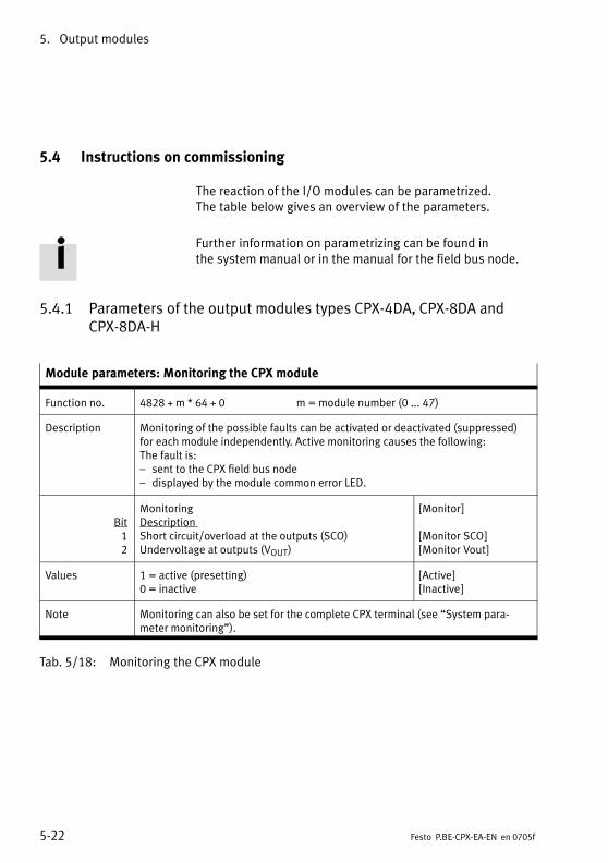
5. Output modules
5−22 Festo P.BE−CPX−EA−EN en 0705f
5.4 Instructions on commissioning
The reaction of the I/O modules can be parametrized. The table below gives an overview of the parameters.
Further information on parametrizing can be found in the system manual or in the manual for the field bus node.
5.4.1 Parameters of the output modules types CPX−4DA, CPX−8DA andCPX−8DA−H
Module parameters: Monitoring the CPX module
Function no. 4828 + m * 64 + 0 m = module number (0 ... 47)
Description Monitoring of the possible faults can be activated or deactivated (suppressed)for each module independently. Active monitoring causes the following: The fault is:� sent to the CPX field bus node� displayed by the module common error LED.
Bit12
MonitoringDescription Short circuit/overload at the outputs (SCO)Undervoltage at outputs (VOUT)
[Monitor]
[Monitor SCO][Monitor Vout]
Values 1 = active (presetting)0 = inactive
[Active][Inactive]
Note Monitoring can also be set for the complete CPX terminal (see �System para�meter monitoring").
Tab.�5/18: Monitoring the CPX module

5. Output modules
5−23Festo P.BE−CPX−EA−EN en 0705f
Module parameters: Reaction after short circuit/overload
Function no. 4828 + m * 64 + 1 m = module number (0 ... 47)
Description Determines in the event of a short circuit of the outputs whether the power is toremain switched off or whether it is to be switched on again automatically.
Bit1
Reaction after short circuit/overloadDescription Short circuit/overload at the outputs (SCO)
[Behaviour after]
[Behaviour after SCO]
Values 0 = VOUT remains switched off (presetting)1 = VOUT switch on again
[Leave switched off ][Resume]
Note With the setting �VOUT remains switched off," the relevant output must be set/reset before the power can be restored. Check which setting is necessary forreliable operation of your system.Detailed description under �Diagnosis," Tab.�5/23.
Tab.�5/19: Reaction after short circuit/overload
Module parameters: Fail safe channel x
Function no. Access to these module parameters is made via protocol−specific functions (see the manual for the field bus node).
Description Fault mode channel x: Hold last stateFault state (presetting)
Fault state channel x: Set outputReset output (presetting)
Note With the aid of the so−called Fail Safe parametrizing, you can specify the signalstatus which the outputs are to assume in the event of field bus communicationfaults (see also CPX system manual).
Tab.�5/20: Fail Safe channel x (channel−specific)
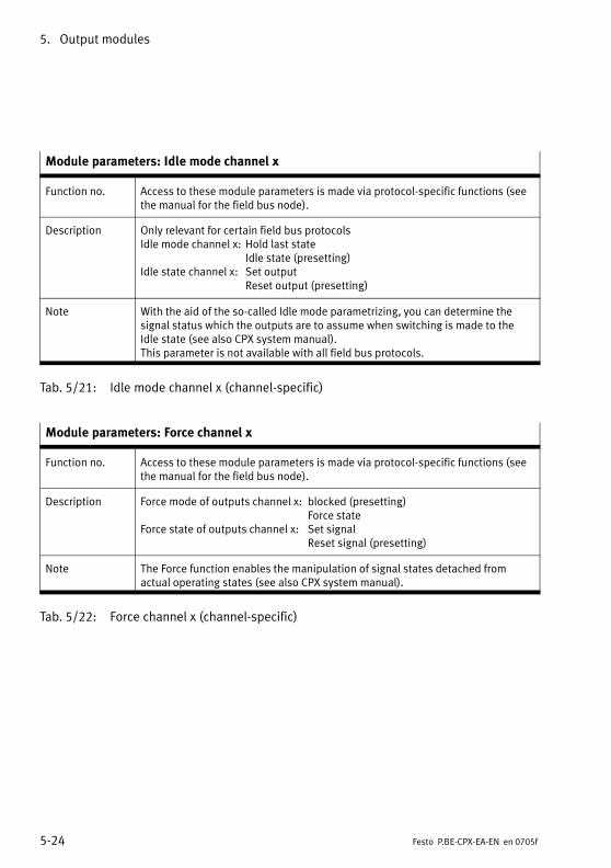
5. Output modules
5−24 Festo P.BE−CPX−EA−EN en 0705f
Module parameters: Idle mode channel x
Function no. Access to these module parameters is made via protocol−specific functions (seethe manual for the field bus node).
Description Only relevant for certain field bus protocolsIdle mode channel x: Hold last state
Idle state (presetting)Idle state channel x: Set output
Reset output (presetting)
Note With the aid of the so−called Idle mode parametrizing, you can determine thesignal status which the outputs are to assume when switching is made to theIdle state (see also CPX system manual).This parameter is not available with all field bus protocols.
Tab.�5/21: Idle mode channel x (channel−specific)
Module parameters: Force channel x
Function no. Access to these module parameters is made via protocol−specific functions (seethe manual for the field bus node).
Description Force mode of outputs channel x: blocked (presetting)Force state
Force state of outputs channel x: Set signalReset signal (presetting)
Note The Force function enables the manipulation of signal states detached fromactual operating states (see also CPX system manual).
Tab.�5/22: Force channel x (channel−specific)

5. Output modules
5−25Festo P.BE−CPX−EA−EN en 0705f
5.5 Diagnosis
Specific faults of the output modules are registered or suppressed depending on the module parametrizing.
The faults are shown on−the−spot by means of the Error LEDand, if necessary, can be evaluated with the handheld (MMI).
Depending on the module parametrizing, the faults are sentto the field bus node, where they can be evaluated accordingto the field bus protocol used.
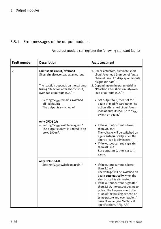
5. Output modules
5−26 Festo P.BE−CPX−EA−EN en 0705f
5.5.1 Error messages of the output modules
An output module can register the following standard faults:
Fault number Description Fault treatment
2 Fault short circuit/overloadShort circuit/overload at an output
The reaction depends on the parame�trizing �Reaction after short circuit/overload at outputs (SCO):"
� Setting �VOUT remains switchedoff" (default): The output is switched off
1. Check actuators, eliminate shortcircuit/overload (number of faultychannel: see LED display or modulediagnostic data).
2. Depending on the parametrizing�Reaction after short circuit/over�load at outputs (SCO):"
· Set output to 0, then set to 1again or modify parameter �Re�action after short circuit/over�load at outputs (SCO)" to �VOUTswitch on again."
only CPX−8DA:� Setting �VOUT switch on again:"
The output current is limited to ap�prox. 250�mA.
· If the output current is lowerthan 400�mA: The voltage will be switched onagain automatically when theshort circuit is eliminated.
· If the output current is greaterthan 400�mA: Set output to 0, then set to 1again.
only CPX−8DA−H:� Setting �VOUT switch on again:" · If the output current is lower
than 2.1�mA: The voltage will be switched onagain automatically when theshort circuit is eliminated.
· If the output current is greaterthan 2.5�A, the output begins topulse. The frequency and dur�ation of the pulsing depend ontemperature and overloading/current value (see �Technicalspecifications," Fig.�A/3)

5. Output modules
5−27Festo P.BE−CPX−EA−EN en 0705f
Fault number Fault treatmentDescription
5 Fault in load voltage for outputsLoad voltage for outputs (VOUT) mis�sing or too low. 1)
· Check the load voltage
1) Tolerance range of the load voltage supply VOUT see �Technical specifications" in the appendix.
Tab.�5/23: Error messages of the output modules
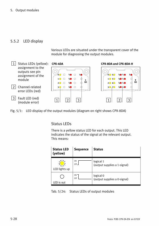
5. Output modules
5−28 Festo P.BE−CPX−EA−EN en 0705f
5.5.2 LED display
Various LEDs are situated under the transparent cover of themodule for diagnosing the output modules.
1 Status LEDs (yellow):assignment to theoutputs see pin assignment of themodule
2 Channel−related error LEDs (red)
3 Fault LED (red)(module error)
0
1
2
3
4DO
1 2
CPX−4DA
3
0
1
2
3
8DO
CPX−8DA and CPX−8DA−H
1
4
5
6
7
2 3
Fig.�5/1: LED display of the output modules (diagram on right shows CPX−8DA)
Status LEDs
There is a yellow status LED for each output. This LED indicates the status of the signal at the relevant output. This means:
Status LED(yellow)
Sequence Status
LED lights up
ON
OFF
logical 1(output supplies a 1−signal)
LED is out
ON
OFFlogical 0(output supplies a 0−signal)
Tab.�5/24: Status LEDs of output modules
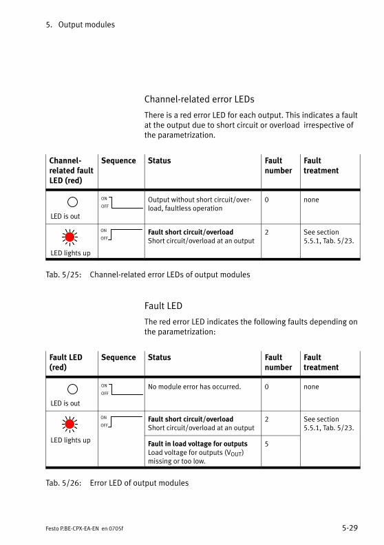
5. Output modules
5−29Festo P.BE−CPX−EA−EN en 0705f
Channel−related error LEDs
There is a red error LED for each output. This indicates a faultat the output due to short circuit or overload irrespective ofthe parametrization.
Channel−related faultLED (red)
Sequence Status Faultnumber
Fault treatment
LED is out
ON
OFF
Output without short circuit/over�load, faultless operation
0 none
LED lights up
ON
OFFFault short circuit/overloadShort circuit/overload at an output
2 See section5.5.1, Tab.�5/23.
Tab.�5/25: Channel−related error LEDs of output modules
Fault LED
The red error LED indicates the following faults depending onthe parametrization:
Fault LED(red)
Sequence Status Faultnumber
Fault treatment
LED is out
ON
OFF
No module error has occurred. 0 none
ON
OFFFault short circuit/overloadShort circuit/overload at an output
2 See section5.5.1, Tab.�5/23.
LED lights upFault in load voltage for outputsLoad voltage for outputs (VOUT)missing or too low.
5
Tab.�5/26: Error LED of output modules

5. Output modules
5−30 Festo P.BE−CPX−EA−EN en 0705f
5.5.3 Fault treatment and parametrizing
The following diagram shows the error treatment in the out�put modules. Further registering and display of the faults canbe suppressed as desired with the appropriate module para�meters, represented in the diagram as switches. The para�meters are described in section 5.4.
2
Error message for the field bus node
...
Fault no. 5
Fault in loadvoltage foroutputs
Fault no. 2
Short circuit/overload atoutput 0
Fault no. 2
Short circuit/overload atoutput 3
Monitoring VOUT
Monitoring SCO
Module faultLED
3
1
Channel−relatederror LEDchannel 3
Channel−relatederror LEDchannel 0
...
0 1 0 1
1 Module parameters (switch position represented = default setting)
2 Module−specific faults
3 Channel−specific faults
Fig.�5/2: Principle of error treatment and parametrizing in the output modules
Multi I/O modules
6−1Festo P.BE−CPX−EA−EN en 0705f
Chapter 6
Type CPX−8DE−8DA
6. Multi I/O modules
6−2 Festo P.BE−CPX−EA−EN en 0705f
Contents
6. Multi I/O modules 6−1 . . . . . . . . . . . . . . . . . . . . . . . . . . . . . . . . . . . . . . . . . . . . . .
6.1 Function of the multi I/O modules 6−4 . . . . . . . . . . . . . . . . . . . . . . . . . . . . . . . . .
6.2 Fitting 6−4 . . . . . . . . . . . . . . . . . . . . . . . . . . . . . . . . . . . . . . . . . . . . . . . . . . . . . . . .
6.3 Installation 6−5 . . . . . . . . . . . . . . . . . . . . . . . . . . . . . . . . . . . . . . . . . . . . . . . . . . . .
6.3.1 Multi I/O module CPX−8DE−8DA 6−6 . . . . . . . . . . . . . . . . . . . . . . . . . . . .
6.4 Instructions on commissioning 6−10 . . . . . . . . . . . . . . . . . . . . . . . . . . . . . . . . . . . .
6.5 Diagnosis 6−16 . . . . . . . . . . . . . . . . . . . . . . . . . . . . . . . . . . . . . . . . . . . . . . . . . . . . .
6.5.1 Error messages of the multi I/O modules 6−16 . . . . . . . . . . . . . . . . . . . .
6.5.2 LED display 6−18 . . . . . . . . . . . . . . . . . . . . . . . . . . . . . . . . . . . . . . . . . . . .
6.5.3 Error treatment and parametrizing 6−20 . . . . . . . . . . . . . . . . . . . . . . . . . .

6. Multi I/O modules
6−3Festo P.BE−CPX−EA−EN en 0705f
Contents of this chapter This chapter describes the CPX multi I/O modules.
The CPX multi I/O modules provide digital inputs and outputsin a CPX terminal and can be adapted to specific applicationsby means of different sub−bases.
Further information An overview of the modular structure of a CPX terminal, themodular connection technology as well as the displays andconnecting elements can be found in chapter 2.
Information on mounting the complete CPX terminal, con�necting the power supply as well as general instructions onconfiguration and parametrizing can be found in the CPX sys�tem manual.
Information on the address assignment as well as on com�missioning can be found in the appropriate field bus nodemanual or function module manual.
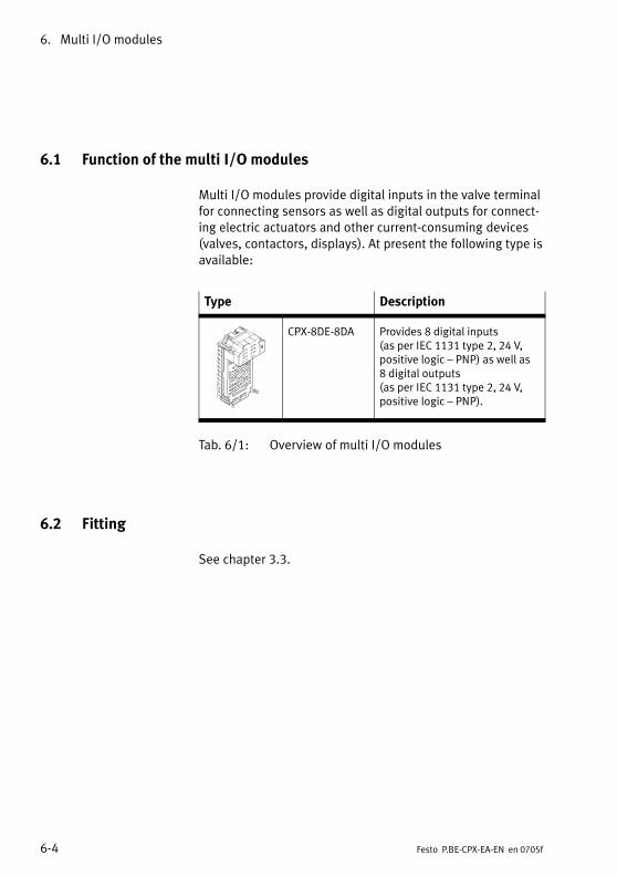
6. Multi I/O modules
6−4 Festo P.BE−CPX−EA−EN en 0705f
6.1 Function of the multi I/O modules
Multi I/O modules provide digital inputs in the valve terminalfor connecting sensors as well as digital outputs for connect�ing electric actuators and other current−consuming devices(valves, contactors, displays). At present the following type isavailable:
Type Description
CPX−8DE−8DA Provides 8 digital inputs (as per IEC 1131 type 2, 24�V,positive logic � PNP) as well as8 digital outputs (as per IEC�1131 type 2, 24�V,positive logic � PNP).
Tab.�6/1: Overview of multi I/O modules
6.2 Fitting
See chapter 3.3.
6. Multi I/O modules
6−5Festo P.BE−CPX−EA−EN en 0705f
6.3 Installation
WarningSudden unexpected movement of the connected actuatorsand uncontrolled movements of loose tubing can causeinjury to human beings or damage to property.
Before carrying out installation and maintenance work,switch off the following:
� the compressed air supply
� the operating and load voltage supplies.
In the following sections you will find the pin assignments of
the multi I/O modules for the different sub−bases.
Instructions on connecting the cables and plugs to the sub−bases can be found in section 3.2.3.
Power supply
The 24 V supply for the outputs is provided via the loadvoltage outputs of the CPX terminal (VOUT).
The 24 V sensor supply for the inputs as well as the powersupply for the electronics of the multi I/O modules is pro�vided via the operating voltage supply for the electronics/sensors (VEL/SEN).
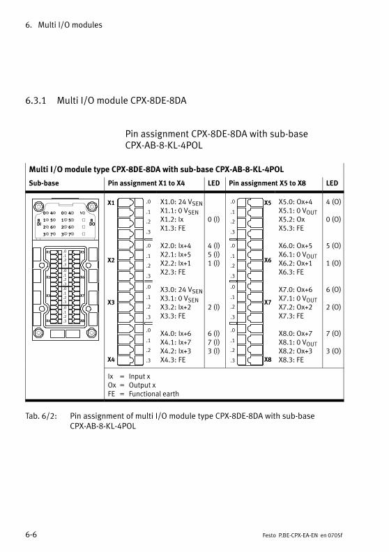
6. Multi I/O modules
6−6 Festo P.BE−CPX−EA−EN en 0705f
6.3.1 Multi I/O module CPX−8DE−8DA
Pin assignment CPX−8DE−8DA with sub−baseCPX−AB−8−KL−4POL
Multi I/O module type CPX−8DE−8DA with sub−base CPX−AB−8−KL−4POL
Sub−base Pin assignment X1 to X4 LED Pin assignment X5 to X8 LED
0
1
2
3
8DI
4
5
6
7
X1
X2
X3
X4
X5
X6
X7
X8
.0
.1
.2
.3
.0
.1
.2
.3
.0
.1
.2
.3
.0
.1
.2
.3
0
1
2
3
4
5
6
7
8DO
X1
X2
X3
X4
.0
.1
.2
.3
.0
.1
.2
.3
.0
.1
.2
.3
.0
.1
.2
.3
X1.0: 24 VSENX1.1: 0 VSENX1.2: IxX1.3: FE
X2.0: Ix+4X2.1: Ix+5X2.2: Ix+1X2.3: FE
X3.0: 24 VSENX3.1: 0 VSENX3.2: Ix+2X3.3: FE
X4.0: Ix+6X4.1: Ix+7X4.2: Ix+3X4.3: FE
0 (I)
4 (I)5 (I)1 (I)
2 (I)
6 (I)7 (I)3 (I)
X5
X6
X7
X8
.0
.1
.2
.3
.0
.1
.2
.3
.0
.1
.2
.3
.0
.1
.2
.3
X5.0: Ox+4X5.1: 0 VOUTX5.2: OxX5.3: FE
X6.0: Ox+5X6.1: 0 VOUTX6.2: Ox+1X6.3: FE
X7.0: Ox+6X7.1: 0 VOUTX7.2: Ox+2X7.3: FE
X8.0: Ox+7X8.1: 0 VOUTX8.2: Ox+3X8.3: FE
4 (O)
0 (O)
5 (O)
1 (O)
6 (O)
2 (O)
7 (O)
3 (O)
Ix = Input xOx = Output xFE = Functional earth
Tab.�6/2: Pin assignment of multi I/O module type CPX−8DE−8DA with sub−baseCPX−AB−8−KL−4POL
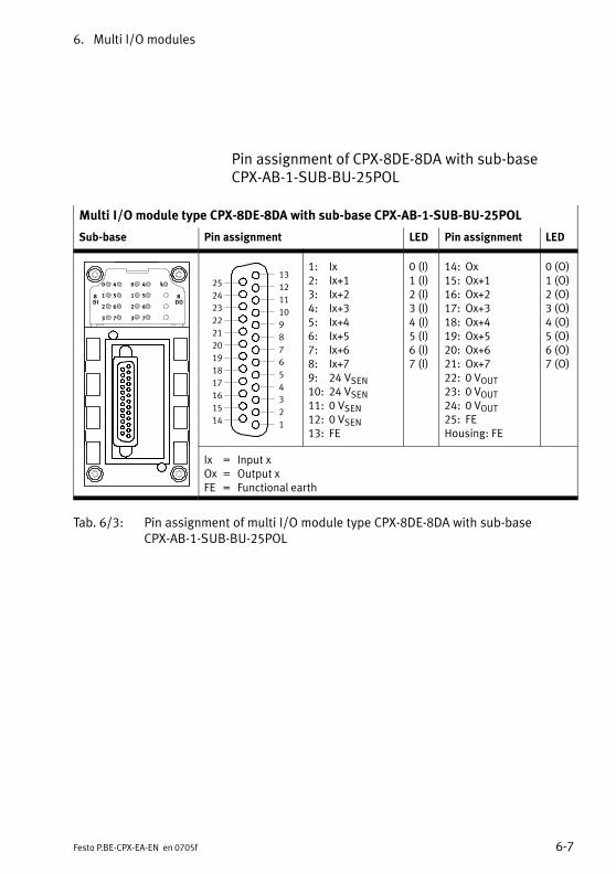
6. Multi I/O modules
6−7Festo P.BE−CPX−EA−EN en 0705f
Pin assignment of CPX−8DE−8DA with sub−baseCPX−AB−1−SUB−BU−25POL
Multi I/O module type CPX−8DE−8DA with sub−base CPX−AB−1−SUB−BU−25POL
Sub−base Pin assignment LED Pin assignment LED
0
1
2
3
8DI
4
5
6
7
0
1
2
3
4
5
6
7
8DO
1
2
3
4
5
6
7
8
9
10
11
12
13
14
15
16
17
18
19
20
21
22
23
24
25
1: Ix2: Ix+13: Ix+24: Ix+35: Ix+46: Ix+57: Ix+68: Ix+79: 24 VSEN10: 24 VSEN11: 0 VSEN12: 0 VSEN13: FE
0 (I)1 (I)2 (I)3 (I)4 (I)5 (I)6 (I)7 (I)
14: Ox15: Ox+116: Ox+217: Ox+318: Ox+419: Ox+520: Ox+621: Ox+722: 0 VOUT23: 0 VOUT24: 0 VOUT25: FEHousing: FE
0 (O)1 (O)2 (O)3 (O)4 (O)5 (O)6 (O)7 (O)
Ix = Input xOx = Output xFE = Functional earth
Tab.�6/3: Pin assignment of multi I/O module type CPX−8DE−8DA with sub−baseCPX−AB−1−SUB−BU−25POL

6. Multi I/O modules
6−8 Festo P.BE−CPX−EA−EN en 0705f
Pin assignment CPX−8DE−8DA with sub−baseCPX−AB−4−M12−8POL
Please noteWith the multi I/O module CPX−8DE−8DA with sub−baseCPX−AB−4−M12−8POL the inputs Ix+4 and Ix+6 are availableon sockets X1 and X3 resp. X2 and X4 (connected inter�nally).
Multi I/O module type CPX−8DE−8DA with sub−base CPX−AB−4−M12−8POL
Sub−base Pin assignment X1, X2 LED Pin assignment X3, X4 LED
0
1
2
3
8DI
4
5
6
7
0
1
2
3
4
5
6
7
8DO
2
3
1
5
4
X2
8
6
7
2
3
1
5
4
X1
8
6
7
Socket X1:1: 24 VSEN2: Ix3: Ix+14: 0 VSEN5: Ox6: Ox+17: Ix+48: 0 VOUT
Socket X2:1: 24 VSEN2: Ix+23: Ix+34: 0 VSEN5: Ox+26: Ox+37: Ix+68: 0 VOUT
0 (I)1 (I)
0 (O)1 (O)4 (I)
2 (I)3 (I)
2 (O)3 (O)6 (I)
2
3
1
5
4
X4
8
6
7
2
3
1
5
4
X3
8
6
7
Socket X3:1: 24 VSEN2: Ix+43: Ix+54: 0 VSEN5: Ox+46: Ox+57: n.c.8: 0 VOUT
Socket X4:1: 24 VSEN2: Ix+63: Ix+74: 0 VSEN5: Ox+66: Ox+77: n.c.8: 0 VOUT
4 (I)5 (I)
4 (O)5 (O)
6 (I)7 (I)
6 (O)7 (O)
Ix = Input xOx = Output xFE = Functional earth
Tab.�6/4: Pin assignment of multi I/O module type CPX−8DE−8DA with sub−baseCPX−AB−4−M12x2−5POL
6. Multi I/O modules
6−9Festo P.BE−CPX−EA−EN en 0705f
Sockets X1 to X4 are designed for connecting cylinder−valvecombinations type DNCV with connecting cable typeKM12−8GD8GS−2−PU.
Please noteInputs Ix+4 and Ix+6 are provided both at pin 7 of socketsX1 and X2 as well as at pin 2 of sockets X3 and X4.
The cylinder−valve combination type DNCV with diagnosticmodule and activated diagnostic output supplies an in�verted diagnostic signal (1−signal = no fault) at pin�7.
When therefore cylinder−valve combinations type DNCVwith diagnostic module and activated diagnostic outputare connected to sockets X1 and X2, pin 2 at sockets X3and X4 cannot be used.
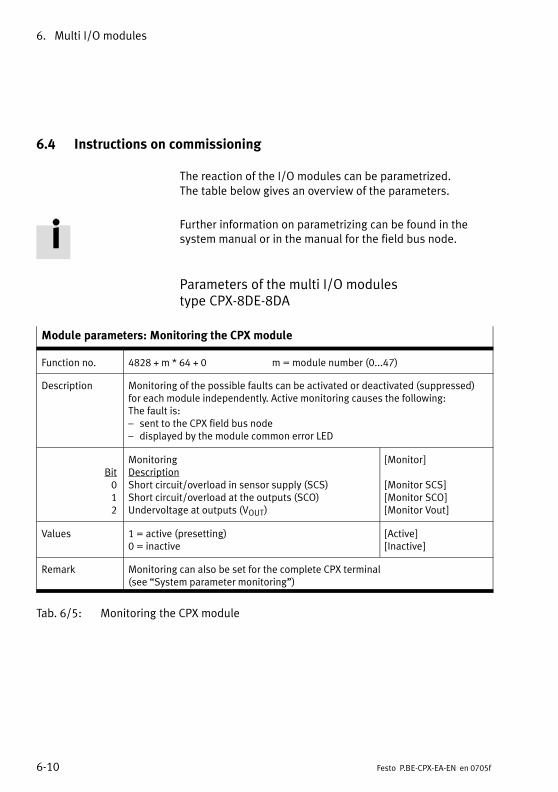
6. Multi I/O modules
6−10 Festo P.BE−CPX−EA−EN en 0705f
6.4 Instructions on commissioning
The reaction of the I/O modules can be parametrized. The table below gives an overview of the parameters.
Further information on parametrizing can be found in thesystem manual or in the manual for the field bus node.
Parameters of the multi I/O modulestype�CPX−8DE−8DA
Module parameters: Monitoring the CPX module
Function no. 4828 + m * 64 + 0 m = module number (0...47)
Description Monitoring of the possible faults can be activated or deactivated (suppressed)for each module independently. Active monitoring causes the following: The fault is:� sent to the CPX field bus node� displayed by the module common error LED
Bit012
MonitoringDescriptionShort circuit/overload in sensor supply (SCS)Short circuit/overload at the outputs (SCO)Undervoltage at outputs (VOUT)
[Monitor]
[Monitor SCS][Monitor SCO][Monitor Vout]
Values 1 = active (presetting)0 = inactive
[Active][Inactive]
Remark Monitoring can also be set for the complete CPX terminal (see �System parameter monitoring")
Tab.�6/5: Monitoring the CPX module
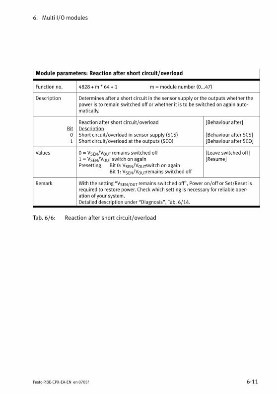
6. Multi I/O modules
6−11Festo P.BE−CPX−EA−EN en 0705f
Module parameters: Reaction after short circuit/overload
Function no. 4828 + m * 64 + 1 m = module number (0...47)
Description Determines after a short circuit in the sensor supply or the outputs whether thepower is to remain switched off or whether it is to be switched on again auto�matically.
Bit01
Reaction after short circuit/overloadDescriptionShort circuit/overload in sensor supply (SCS)Short circuit/overload at the outputs (SCO)
[Behaviour after]
[Behaviour after SCS][Behaviour after SCO]
Values 0 = VSEN/VOUT remains switched off1 = VSEN/VOUT switch on againPresetting: Bit 0: VSEN/VOUTswitch on again
Bit 1: VSEN/VOUTremains switched off
[Leave switched off ][Resume]
Remark With the setting �VSEN/OUT remains switched off", Power on/off or Set/Reset isrequired to restore power. Check which setting is necessary for reliable oper�ation of your system.Detailed description under �Diagnosis", Tab.�6/14.
Tab.�6/6: Reaction after short circuit/overload

6. Multi I/O modules
6−12 Festo P.BE−CPX−EA−EN en 0705f
Module parameters: Input debouncing time
Function no. 4828 + m * 64 + 1 m = module number (0...47)
Description Determines when a change of edge of the sensor signal on this module is to beaccepted as a logical input signal.
Bit Bits 4, 5
ValuesBit 5 4
0 00 11 01 1
Input debouncing timeDescription0.1 ms3 ms (presetting)10 ms20 ms
[Debounce time]
Remark Input debouncing times are specified in order to eliminate interfering changes ofsignal edge during switching procedures (bouncing of the input signal). Thissetting applies to all inputs of the module.Further information on this parameter can be found in the CPX system manual.
Tab.�6/7: Input debouncing time
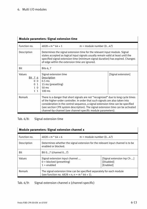
6. Multi I/O modules
6−13Festo P.BE−CPX−EA−EN en 0705f
Module parameters: Signal extension time
Function no. 4828 + m * 64 + 1 m = module number (0...47)
Description Determines the signal extension time for the relevant input module. Signalstates accepted as logical input signals usually remain valid at least until thespecified signal extension time (minimum signal duration) has expired. Changesof edge within the extension time are ignored.
Bit Bits 6, 7
ValuesBit 7 6
0 00 11 01 1
Signal extension timeDescription0.5 ms15 ms (presetting)50 ms100 ms
[Signal extension]
Remark There is a danger that short signals are not �recognized" due to long cycle timesof the higher−order controller. In order that such signals are also taken intoconsideration in the control sequence, a signal extension time can be specified(see section CPX system description). The signal extension time can be activatedchannel−by−channel (see channel−specific module parameters).
Tab.�6/8: Signal extension time
Module parameters: Signal extension channel x
Function no. 4828 + m * 64 + 6 m = module number (0...47)
Description Determines whether the signal extension for the relevant input channel is to beenabled or blocked.
Bit Bit 0...7 (channel 0...7)
Values Signal extension input channel ...0 = blocked (presetting)1 = enabled
[Signal extension Inp Ch ...][Disabled][Enabled]
Remark The signal extension time can be specified separately for each module (see function no. 4828 + n; n = m * 64 + 1).
Tab.�6/9: Signal extension channel x (channel−specific)
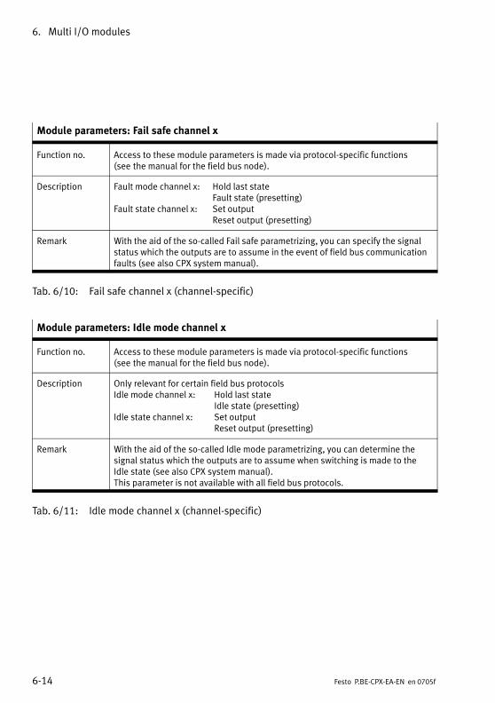
6. Multi I/O modules
6−14 Festo P.BE−CPX−EA−EN en 0705f
Module parameters: Fail safe channel x
Function no. Access to these module parameters is made via protocol−specific functions(see�the manual for the field bus node).
Description Fault mode channel x: Hold last stateFault state (presetting)
Fault state channel x: Set outputReset output (presetting)
Remark With the aid of the so−called Fail safe parametrizing, you can specify the signalstatus which the outputs are to assume in the event of field bus communicationfaults (see also CPX system manual).
Tab.�6/10: Fail safe channel x (channel−specific)
Module parameters: Idle mode channel x
Function no. Access to these module parameters is made via protocol−specific functions(see�the manual for the field bus node).
Description Only relevant for certain field bus protocolsIdle mode channel x: Hold last state
Idle state (presetting)Idle state channel x: Set output
Reset output (presetting)
Remark With the aid of the so−called Idle mode parametrizing, you can determine thesignal status which the outputs are to assume when switching is made to theIdle state (see also CPX system manual).This parameter is not available with all field bus protocols.
Tab.�6/11: Idle mode channel x (channel−specific)

6. Multi I/O modules
6−15Festo P.BE−CPX−EA−EN en 0705f
Module parameters: Force channel x
Function no. Access to these module parameters is made via protocol−specific functions(see�the manual for the field bus node).
Description Force mode of inputs channel x: Blocked (presetting)Force state
Force state of inputs channel x: Set signalReset signal (presetting)
Force mode of outputs chanel x: Blocked (presetting)Force state
Force state of outputs channel x: Set signalReset signal (presetting)
Remark The Force function enables the manipulation of signal states detached fromactual operating states (see also CPX system manual).
Tab.�6/12: Force channel x (channel−specific)
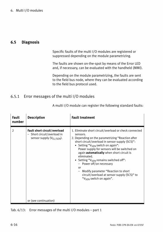
6. Multi I/O modules
6−16 Festo P.BE−CPX−EA−EN en 0705f
6.5 Diagnosis
Specific faults of the multi I/O modules are registered orsuppressed depending on the module parametrizing.
The faults are shown on−the−spot by means of the Error LEDand, if necessary, can be evaluated with the handheld (MMI).
Depending on the module parametrizing, the faults are sentto the field bus node, where they can be evaluated accordingto the field bus protocol used.
6.5.1 Error messages of the multi I/O modules
A multi I/O module can register the following standard faults:
Faultnumber
Description Fault treatment
2 Fault short circuit/overload� Short circuit/overload in
sensor supply (VEL/SEN).
or (see continuation)
1. Eliminate short circuit/overload or check connectedsensors.
2. Depending on the parametrizing �Reaction aftershort circuit/overload in sensor supply (SCS)":· Setting �VSEN switch on again":
Power supply for sensors will be switched onagain automatically when short circuit iseliminated.
· Setting �VSEN remains switched off":� Power off/on necessaryor� Modify parameter �Reaction to short
circuit/overload at sensor supply (SCS)" to �VSEN switch on again".
Tab.�6/13: Error messages of the multi I/O modules � part 1

6. Multi I/O modules
6−17Festo P.BE−CPX−EA−EN en 0705f
Faultnumber
Description Fault treatment
2 (con�tinuation)
Fault short circuit/overloadShort circuit/overload at an output
The reaction depends on theparametrizing �Reaction after shortcircuit/overload at outputs (SCO)":
� Setting �VOUT remains switchedoff" (default): The output is switched off
� Setting �VOUT switch on agai":The output current is limited toapprox. 250�mA.
1. Check actuators, eliminate short circuit/over�load (number of faulty channel: see modulediagnostic data).
2. Depending on the parametrizing �Reactionafter short circuit/overload at outputs (SCO)":
· Set output to 0, then set to 1 again ormodify parameter �Reaction after shortcircuit/overload at outputs (SCO)" to �VOUTswitch on again".
· If the output current is lower than 400�mA: The voltage will be switched on againautomatically when the short circuit iseliminated. If the output current is greaterthan 400�mA: Set output to 0, then set to 1 again.
5 Fault in load voltage for outputsLoad voltage for outputs (VOUT)missing or too low. 1)
· Check the load voltage
1) Tolerance range of the load voltage supply VOUT see �Technical specifications" in the appendix.
Tab.�6/14: Error messages of the multi I/O modules � part 2
Please notePlease note when using the multi I/O modules:
� If there is a short circuit, all sensor supplies will beswitched off together.
� If not parametrized otherwise, the sensor supply voltagewill be switched on again automatically when the shortcircuit is eliminated.
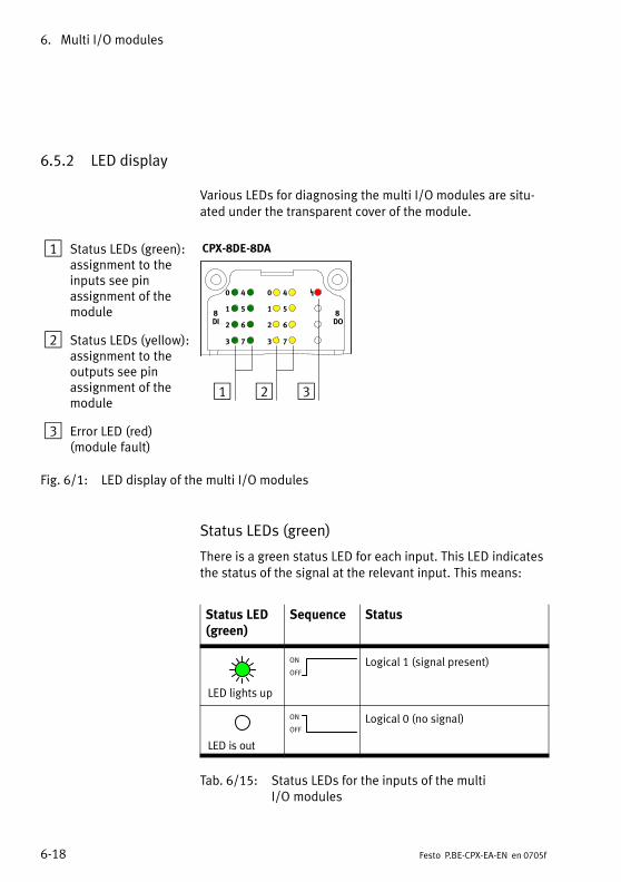
6. Multi I/O modules
6−18 Festo P.BE−CPX−EA−EN en 0705f
6.5.2 LED display
Various LEDs for diagnosing the multi I/O modules are situ�ated under the transparent cover of the module.
1 Status LEDs (green):assignment to theinputs see pinassignment of themodule
2 Status LEDs (yellow):assignment to theoutputs see pinassignment of themodule
3 Error LED (red)(module fault)
0
1
2
3
8DI
4
5
6
7
1 2
CPX−8DE−8DA
0
1
2
3
4
5
6
7
8DO
3
Fig.�6/1: LED display of the multi I/O modules
Status LEDs (green)
There is a green status LED for each input. This LED indicatesthe status of the signal at the relevant input. This means:
Status LED(green)
Sequence Status
LED lights up
ON
OFF
Logical 1 (signal present)
LED is out
ON
OFF
Logical 0 (no signal)
Tab.�6/15: Status LEDs for the inputs of the multiI/O�modules
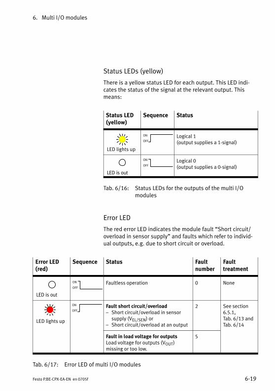
6. Multi I/O modules
6−19Festo P.BE−CPX−EA−EN en 0705f
Status LEDs (yellow)
There is a yellow status LED for each output. This LED indi�cates the status of the signal at the relevant output. Thismeans:
Status LED(yellow)
Sequence Status
LED lights up
ON
OFF
Logical 1(output supplies a 1−signal)
LED is out
ON
OFFLogical 0(output supplies a 0−signal)
Tab.�6/16: Status LEDs for the outputs of the multi I/Omodules
Error LED
The red error LED indicates the module fault �Short circuit/overload in sensor supply" and faults which refer to individ�ual outputs, e.g. due to short circuit or overload.
Error LED(red)
Sequence Status Faultnumber
Faulttreatment
LED is out
ON
OFF
Faultless operation 0 None
LED lights up
ON
OFFFault short circuit/overload� Short circuit/overload in sensor
supply (VEL/SEN) or� Short circuit/overload at an output
2 See section6.5.1,Tab.�6/13 andTab.�6/14
Fault in load voltage for outputsLoad voltage for outputs (VOUT)missing or too low.
5
Tab.�6/17: Error LED of multi I/O modules
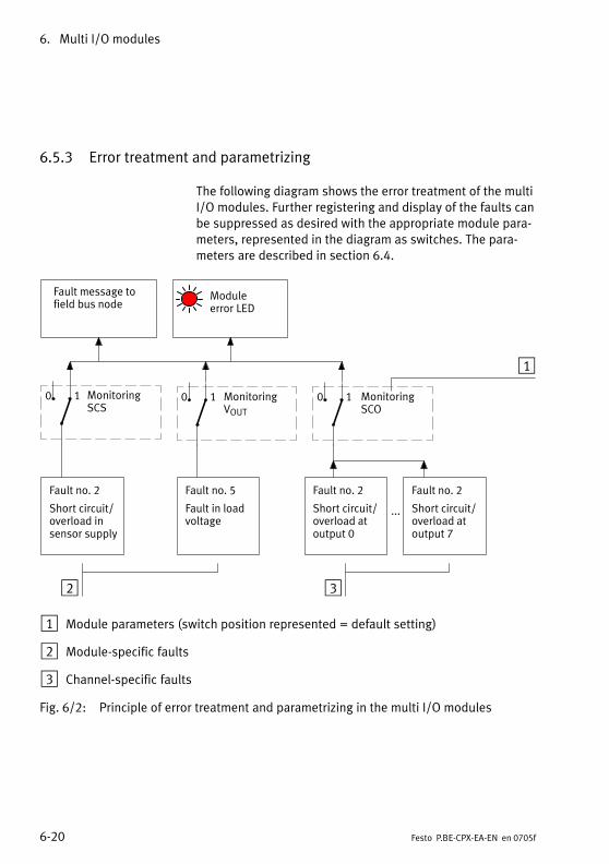
6. Multi I/O modules
6−20 Festo P.BE−CPX−EA−EN en 0705f
6.5.3 Error treatment and parametrizing
The following diagram shows the error treatment of the multiI/O modules. Further registering and display of the faults canbe suppressed as desired with the appropriate module para�meters, represented in the diagram as switches. The para�meters are described in section 6.4.
2
Fault no. 2
Short circuit/overload insensor supply
Fault message tofield bus node
...
Fault no. 5
Fault in loadvoltage
Fault no. 2
Short circuit/overload atoutput 0
Fault no. 2
Short circuit/overload atoutput 7
MonitoringSCS
MonitoringVOUT
MonitoringSCO
Module error LED
3
1
0 1 0 1 0 1
1 Module parameters (switch position represented = default setting)
2 Module−specific faults
3 Channel−specific faults
Fig.�6/2: Principle of error treatment and parametrizing in the multi I/O modules
Technical appendix
A−1Festo P.BE−CPX−EA−EN en 0705f
Appendix A
A. Technical appendix
A−2 Festo P.BE−CPX−EA−EN en 0705f
Contents
A. Technical appendix A−1 . . . . . . . . . . . . . . . . . . . . . . . . . . . . . . . . . . . . . . . . . . . . .
A.1 Technical specifications of the pneumatic interfaces A−3 . . . . . . . . . . . . . . . . . . .
A.2 Technical specifications of the MPA electronic modules A−5 . . . . . . . . . . . . . . . .
A.3 Technical specifications of the input modules A−7 . . . . . . . . . . . . . . . . . . . . . . . .
A.4 Technical specifications of the output modules A−10 . . . . . . . . . . . . . . . . . . . . . . .
A.5 Technical specifications of the multi I/O modules A−13 . . . . . . . . . . . . . . . . . . . . .
A.6 Technical specifications of the sub−bases A−15 . . . . . . . . . . . . . . . . . . . . . . . . . . . .
A.7 Technical specifications of the sub−bases in metal design A−16 . . . . . . . . . . . . . .
A.8 Internal structure of the CPX modules A−17 . . . . . . . . . . . . . . . . . . . . . . . . . . . . . .
A.9 Examples of circuitry A−22 . . . . . . . . . . . . . . . . . . . . . . . . . . . . . . . . . . . . . . . . . . . .
A.9.1 Circuitry examples of PNP inputs A−22 . . . . . . . . . . . . . . . . . . . . . . . . . . .
A.9.2 Circuitry examples of PNP outputs A−22 . . . . . . . . . . . . . . . . . . . . . . . . . .
A.9.3 Circuitry examples of NPN inputs A−23 . . . . . . . . . . . . . . . . . . . . . . . . . . .
A.9.4 Circuitry example with DUO cable A−24 . . . . . . . . . . . . . . . . . . . . . . . . . .
A.9.5 Circuitry example with DNCV A−25 . . . . . . . . . . . . . . . . . . . . . . . . . . . . . .
A.10 Accessories A−26 . . . . . . . . . . . . . . . . . . . . . . . . . . . . . . . . . . . . . . . . . . . . . . . . . . . .
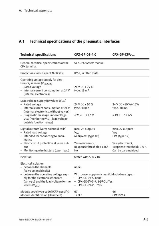
A. Technical appendix
A−3Festo P.BE−CPX−EA−EN en 0705f
A.1 Technical specifications of the pneumatic interfaces
Technical specifications CPX−GP−03−4.0 CPX−GP−CPA−...
General technical specifications of theCPX terminal
See CPX system manual
Protection class as per EN 60 529 IP65, in fitted state
Operating voltage supply for elec�tronics/sensors (VEL/SEN)� Rated voltage� Internal current consumption at 24 V
(internal electronics)
24 V DC ± 25 %type. 15 mA
Load voltage supply for valves (VVAL)� Rated voltage� Internal current consumption at 24 V
(internal electronics, without valves)� Diagnostic message undervoltage
VVAL (monitoring VVAL, load voltageoutside function range)
24 V DC ± 10 %type. 30 mA
� 21.6 ... 21.5 V
24 V DC +10 %/−15%type. 30 mA
� 19.8 ... 19.6 V
Digital outputs (valve solenoid coils)� Rated load voltage� Intended for connecting to pneu�
matics� Short circuit protection at valve out�
put� Monitoring wire fracture (open load)
max. 26 outputsVVALMidi/Maxi (type 03)
Yes (electronic),Response threshold > 1.0 ANo
max. 22 outputsVVALCPA (type 12)
Yes (electronic),Response threshold > 1.0 ACan be parametrized
Isolation tested with 500 V DC
Electrical isolation� between the channels
(valve solenoid coils)� between the operating voltage sup�
ply for the electronics/sensors(VEL/SEN) and the load voltage for thevalves (VVAL)
none
With power supply via manifold sub−base type:� CPX−GE−EV−S: none� CPX−GE−EV−S−7/8−5POL: Yes� CPX−GE−EV−V...: Yes
Module code [type code] (CPX−specific)Module identification (Handheld)
67TYPE3
66CPA10/14
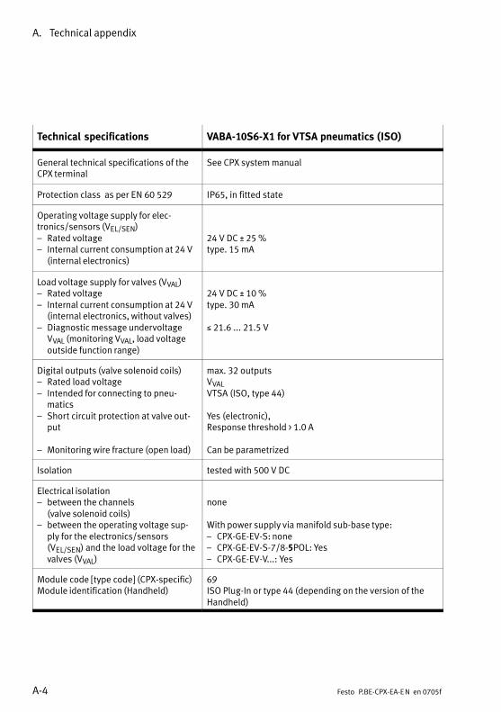
A. Technical appendix
A−4 Festo P.BE−CPX−EA−EN en 0705f
Technical specifications VABA−10S6−X1 for VTSA pneumatics (ISO)
General technical specifications of theCPX terminal
See CPX system manual
Protection class as per EN 60 529 IP65, in fitted state
Operating voltage supply for elec�tronics/sensors (VEL/SEN)� Rated voltage� Internal current consumption at 24 V
(internal electronics)
24 V DC ± 25 %type. 15 mA
Load voltage supply for valves (VVAL)� Rated voltage� Internal current consumption at 24 V
(internal electronics, without valves)� Diagnostic message undervoltage
VVAL (monitoring VVAL, load voltageoutside function range)
24 V DC ± 10 %type. 30 mA
� 21.6 ... 21.5 V
Digital outputs (valve solenoid coils)� Rated load voltage� Intended for connecting to pneu�
matics� Short circuit protection at valve out�
put
� Monitoring wire fracture (open load)
max. 32 outputsVVALVTSA (ISO, type 44)
Yes (electronic),Response threshold > 1.0 A
Can be parametrized
Isolation tested with 500 V DC
Electrical isolation� between the channels
(valve solenoid coils)� between the operating voltage sup�
ply for the electronics/sensors(VEL/SEN) and the load voltage for thevalves (VVAL)
none
With power supply via manifold sub−base type:� CPX−GE−EV−S: none� CPX−GE−EV−S−7/8−5POL: Yes� CPX−GE−EV−V...: Yes
Module code [type code] (CPX−specific)Module identification (Handheld)
69ISO Plug−In or type 44 (depending on the version of theHandheld)

A. Technical appendix
A−5Festo P.BE−CPX−EA−EN en 0705f
A.2 Technical specifications of the MPA electronic modules
Technical specifications VMPA1−FB−EMG−8 VMPA1−FB−EMS−8
General technical specifications of the CPX terminal
See CPX system manual
Protection class as per EN 60 529 IP 65, in fitted state (MPA pneumatic module fittedcompletely)
Operating voltage supply for the elec�tronics (VEL/SEN)� Rated voltage� Maximum internal current consumption
at 24 V (irrespective of switching statusof the valves)
24 V DC ± 25 %20 mA
Load voltage supply for valves (VVAL)� Rated voltage� Maximum internal current consumption
at 24 V (irrespective of switching statusof the valves)
� Diagnostic message undervoltage VVAL(monitoring VVAL, load voltage outsidefunction range)
24 V DC ± 25 %type. 25 mA
� 17.5 ... 16.0 V
24 V DC ± 25 %type. 8 mA
� 17.5 ... 16.0 V
Digital outputs (valve solenoid coils)� Short circuit protection at valve output� Maximum current consumption per sole�
noid coil out of load voltage VVAL at 24 V� Rated pick−up current/duration� Nominal current with current reduction
8 outputsYes (electronic)
45 mA / 20 ms8 mA after 20 ms
Isolation tested with 500 V DC
Electrical isolation� between the channels
(valve solenoid coils)none
With power supply via manifold sub−base type:
� between the operating voltage supplyfor the electronics/sensors (VEL/SEN) andthe load voltage for the valves (VVAL)
� CPX−GE−EV−S: none� ...−EV−S−7/8−5POL: Yes� CPX−GE−EV−V...: Yes
� CPX−GE−EV−S: none� ...−EV−S−7/8−5POL:
not permitted� CPX−GE−EV−V.: not per�
mitted
Module code [type code] (CPX−specific)Module identification (Handheld)
80MPA1G
82MPA1S
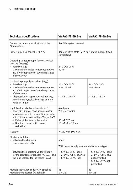
A. Technical appendix
A−6 Festo P.BE−CPX−EA−EN en 0705f
Technical specifications VMPA2−FB−EMG−4 VMPA2−FB−EMS−4
General technical specifications of the CPX terminal
See CPX system manual
Protection class asper EN 60 529 IP 65, in fitted state (MPA pneumatic module fittedcompletely)
Operating voltage supply for electronics/sensors (VEL/SEN)� Rated voltage� Maximum internal current consumption
at 24 V (irrespective of switching statusof the valves)
24 V DC ± 25 %20 mA
Load voltage supply for valves (VVAL)� Rated voltage� Maximum internal current consumption
at 24 V (irrespective of switching statusof the valves)
� Diagnostic message undervoltage VVAL(monitoring VVAL, load voltage outsidefunction range)
24 V DC ± 25 %type. 25 mA
� 17.5 ... 16.0 V
24 V DC ± 25 %type. 8 mA
� 17.5 ... 16.0 V
Digital outputs (valve solenoid coils)� Short circuit protection at valve output� Maximum current consumption per sole�
noid coil out of load voltage VVAL at 24 V� Rated pick−up current/duration� Nominal current with current
reduction
4 outputsYes (electronic)
90 mA / 20 ms18 mA after 20 ms
Isolation tested with 500 V DC
Electrical isolation� between the channels
(valve solenoid coils)none
With power supply via manifold sub−base type:
� between the operating voltage supplyfor the electronics/sensors (VEL/SEN) andthe load voltage for the valves (VVAL)
� CPX−GE−EV−S: none� ...−EV−S−7/8−5POL: Yes� CPX−GE−EV−V...: Yes
� CPX−GE−EV−S: none� ...−EV−S−7/8−5POL:
not permitted� CPX−GE−EV−V.: not
permitted
Module code [type code] (CPX−specific)Module identification (Handheld)
81MPA2G
83MPA2S
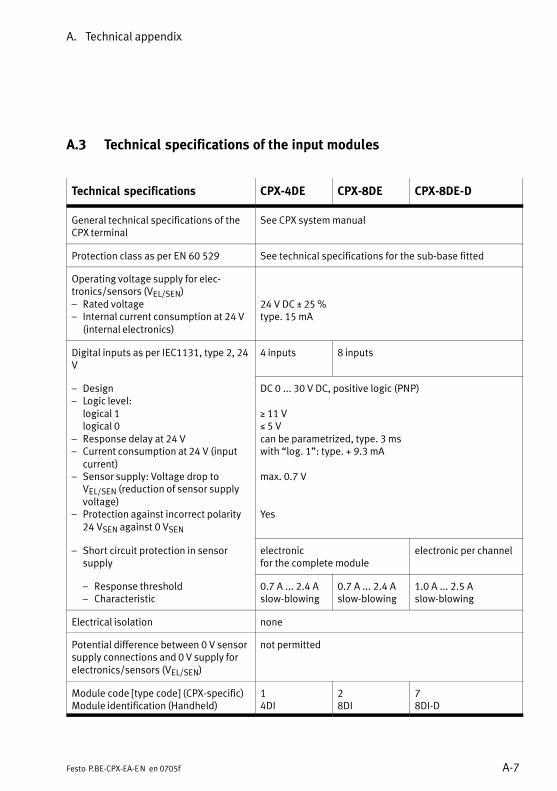
A. Technical appendix
A−7Festo P.BE−CPX−EA−EN en 0705f
A.3 Technical specifications of the input modules
Technical specifications CPX−4DE CPX−8DE CPX−8DE−D
General technical specifications of theCPX terminal
See CPX system manual
Protection class as per EN 60 529 See technical specifications for the sub−base fitted
Operating voltage supply for elec�tronics/sensors (VEL/SEN)� Rated voltage� Internal current consumption at 24 V
(internal electronics)
24 V DC ± 25 %type. 15 mA
Digital inputs as per IEC1131, type 2, 24V
4 inputs 8 inputs
� Design� Logic level:
logical 1logical 0
� Response delay at 24 V� Current consumption at 24�V (input
current)� Sensor supply: Voltage drop to
VEL/SEN (reduction of sensor supplyvoltage)
� Protection against incorrect polarity24 VSEN against 0 VSEN
DC 0 ... 30 V DC, positive logic (PNP)
� 11 V� 5 Vcan be parametrized, type. 3 mswith �log. 1": type. +�9.3 mA
max. 0.7 V
Yes
� Short circuit protection in sensorsupply
electronicfor the complete module
electronic per channel
� Response threshold� Characteristic
0.7 A ... 2.4 Aslow−blowing
0.7 A ... 2.4 Aslow−blowing
1.0 A ... 2.5 A slow−blowing
Electrical isolation none
Potential difference between 0 V sensorsupply connections and 0 V supply forelectronics/sensors (VEL/SEN)
not permitted
Module code [type code] (CPX−specific)Module identification (Handheld)
14DI
28DI
78DI−D
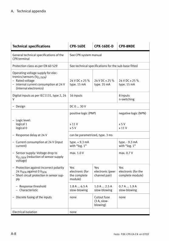
A. Technical appendix
A−8 Festo P.BE−CPX−EA−EN en 0705f
Technical specifications CPX−16DE CPX−16DE−D CPX−8NDE
General technical specifications of theCPX terminal
See CPX system manual
Protection class as per EN 60 529 See technical specifications for the sub−base fitted
Operating voltage supply for elec�tronics/sensors (VEL/SEN)� Rated voltage� Internal current consumption at 24 V
(internal electronics)
24 V DC ± 25 %type. 15 mA
24 V DC ± 25 %type. 35 mA
24 V DC ± 25 %type. 15 mA
Digital inputs as per IEC1131, type 2, 24V
16 inputs 8 inputsn−switching
� Design DC 0 ... 30 V
positive logic (PNP) negative logic (NPN)
� Logic level:logical 1logical 0
� 11 V� 5 V
� 5 V� 11 V
� Response delay at 24 V can be parametrized, type. 3 ms
� Current consumption at 24�V (inputcurrent)
type. +�9.3 mAwith �log. 1"
type. −�9.3 mAwith �log. 1"
� Sensor supply: Voltage drop toVEL/SEN (reduction of sensor supplyvoltage)
max. 1.0 V max. 0.7 V
� Protection against incorrect polarity24 VSEN against 0 VSEN
� Short circuit protection in sensor sup�ply
Yeselectronic (forthe completemodule)
Yeselectronic (peerchannel pair)
Yeselectronic (for thecomplete module)
� Response threshold� Characteristic
1.8 A ... 6.5 Aslow−blowing
1.0 A ... 2.5 Aslow−blowing
0.7 A ... 1.9 Aslow−blowing
� Discrete fusing of the inputs none Cutout fuse(3�A, slow−blowing)
none
Electrical isolation none

A. Technical appendix
A−9Festo P.BE−CPX−EA−EN en 0705f
Technical specifications CPX−8NDECPX−16DE−DCPX−16DE
Potential difference between sensorsupply connections and supply VEL/SEN
0�V−connec�tions: not per�mitted
24 V connections:not permitted
Module code [type code] (CPX−specific)Module identification (Handheld)
1116DI
16M−16DI−D
148NDI
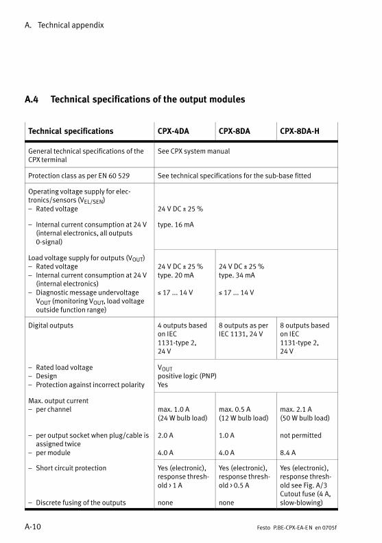
A. Technical appendix
A−10 Festo P.BE−CPX−EA−EN en 0705f
A.4 Technical specifications of the output modules
Technical specifications CPX−4DA CPX−8DA CPX−8DA−H
General technical specifications of theCPX terminal
See CPX system manual
Protection class as per EN 60 529 See technical specifications for the sub−base fitted
Operating voltage supply for elec�tronics/sensors (VEL/SEN)� Rated voltage 24 V DC ± 25 %
� Internal current consumption at 24 V(internal electronics, all outputs0−signal)
type. 16 mA
Load voltage supply for outputs (VOUT)� Rated voltage� Internal current consumption at 24 V
(internal electronics)� Diagnostic message undervoltage
VOUT (monitoring VOUT, load voltageoutside function range)
24 V DC ± 25 %type. 20 mA
� 17 ... 14 V
24 V DC ± 25 %type. 34 mA
� 17 ... 14 V
Digital outputs 4 outputs basedon IEC1131−type�2,24�V
8 outputs as perIEC 1131, 24 V
8 outputs basedon IEC1131−type�2,24�V
� Rated load voltage� Design� Protection against incorrect polarity
VOUTpositive logic (PNP)Yes
Max. output current� per channel
� per output socket when plug/cable isassigned twice
� per module
max. 1.0�A (24�W bulb load)
2.0�A
4.0�A
max. 0.5�A (12�W bulb load)
1.0�A
4.0�A
max. 2.1�A(50�W bulb load)
not permitted
8.4�A
� Short circuit protection
� Discrete fusing of the outputs
Yes (electronic),response thresh�old > 1 A
none
Yes (electronic),response thresh�old > 0.5 A
none
Yes (electronic),response thresh�old see Fig.�A/3Cutout fuse (4�A,slow−blowing)
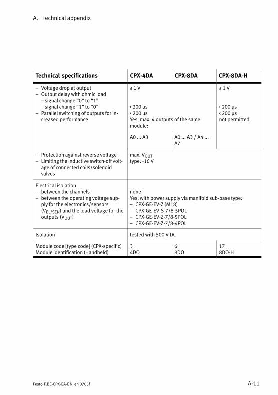
A. Technical appendix
A−11Festo P.BE−CPX−EA−EN en 0705f
Technical specifications CPX−8DA−HCPX−8DACPX−4DA
� Voltage drop at output� Output delay with ohmic load
� signal change �0" to �1"� signal change �1" to �0"
� Parallel switching of outputs for in�creased performance
� 1 V
< 200 s< 200 sYes, max. 4 outputs of the same module:
� 1 V
< 200 s< 200 snot permitted
A0 ... A3 A0 ... A3 / A4 ...A7
� Protection against reverse voltage� Limiting the inductive switch−off volt�
age of connected coils/solenoidvalves
max. VOUTtype. −16 V
Electrical isolation� between the channels� between the operating voltage sup�
ply for the electronics/sensors(VEL/SEN) and the load voltage for theoutputs (VOUT)
noneYes, with power supply via manifold sub−base type:� CPX−GE−EV−Z (M18)� CPX−GE−EV−S−7/8−5POL� CPX−GE−EV−Z−7/8−5POL� CPX−GE−EV−Z−7/8−4POL
Isolation tested with 500 V DC
Module code [type code] (CPX−specific)Module identification (Handheld)
34DO
68DO
178DO−H
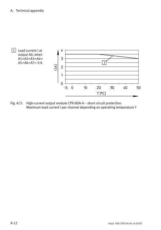
A. Technical appendix
A−12 Festo P.BE−CPX−EA−EN en 0705f
1 Load current�I atoutput A0, whenA1=A2=A3=A4=A5=A6=A7= 0�A
Fig.�A/3: High−current output module CPX−8DA−H � short circuit protection:Maximum load current�I per channel depending on operating temperature�T

A. Technical appendix
A−13Festo P.BE−CPX−EA−EN en 0705f
A.5 Technical specifications of the multi I/O modules
Technical specifications CPX−8DE−8DA
General technical specifications of theCPX terminal
See CPX system manual
Protection class as per EN 60 529 See technical specifications for the sub−base fitted
Operating voltage supply for elec�tronics/sensors (VEL/SEN)� Rated voltage� Internal current consumption at 24 V
(internal electronics, all outputs0−signal)
24 V DC ± 25 %type. 22 mA
Load voltage supply for outputs (VOUT)� Rated voltage� Internal current consumption at 24 V
(internal electronics)� Diagnostic message undervoltage
VOUT (monitoring VOUT, load voltageoutside function range)
24 V DC ± 25 %type. 34 mA
� 17 ... 14 V
Digital inputs� Design� Logic level:
logical 1logical 0
� Response delay at 24 V� Current consumption at 24�V (input
current)� Sensor supply: Voltage drop to
VEL/SEN (reduction of sensor supplyvoltage)
� Protection against incorrect polarity24 VOUT against 0 VSEN
� Short circuit protection in sensorsupply (for the complete module)� Response threshold� Characteristic
8 inputs as per IEC 1131, type 2, 24 V0 ... 30 V DC, positive logic (PNP)
� 11 V� 5 Vcan be parametrized, type. 3 mswith �log. 1": typ. +�9.3 mA
max. 0.7 V
Yes
electronic
0.7 A ... 2.4 Aslow−blowing
Electrical isolation of inputs none
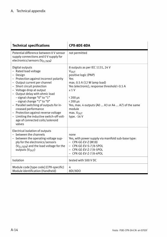
A. Technical appendix
A−14 Festo P.BE−CPX−EA−EN en 0705f
Technical specifications CPX−8DE−8DA
Potential difference between 0 V sensorsupply connections and 0 V supply forelectronics/sensors (VEL/SEN)
not permitted
Digital outputs� Rated load voltage� Design� Protection against incorrect polarity� Output current per channel� Short circuit protection� Voltage drop at output� Output delay with ohmic load
� signal change �0" to �1"� signal change �1" to �0"
� Parallel switching of outputs for in�creased performance
� Protection against reverse voltage� Limiting the inductive switch−off volt�
age of connected coils/solenoidvalves
8 outputs as per IEC 1131, 24 VVOUTpositive logic (PNP)Yesmax. 0.5 A (12 W lamp load)Yes (electronic), response threshold > 0.5 A� 1 V
< 200 s< 200 sYes, max. 4 outputs (A0 ... A3 or A4 ... A7) of the samemodulemax. VOUTtype. −16 V
Electrical isolation of outputs� between the channels� between the operating voltage sup�
ply for the electronics/sensors(VEL/SEN) and the load voltage for theoutputs (VOUT)
noneYes, with power supply via manifold sub−base type:� CPX−GE−EV−Z (M18)� CPX−GE−EV−S−7/8−5POL� CPX−GE−EV−Z−7/8−5POL� CPX−GE−EV−Z−7/8−4POL
Isolation tested with 500 V DC
Module code [type code] (CPX−specific)Module identification (Handheld)
48DI/8DO
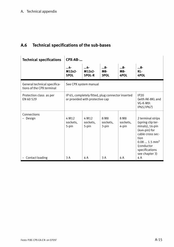
A. Technical appendix
A−15Festo P.BE−CPX−EA−EN en 0705f
A.6 Technical specifications of the sub−bases
Technical specifications CPX−AB−...
...4−M12x2−5POL
...4−M12x2−5POL−R
...8−M8−3POL
...8−M8−4POL
...8−KL−4POL
General technical specifica�tions of the CPX terminal
See CPX system manual
Protection class as per EN 60 529
IP 65, completely fitted, plug connector insertedor provided with protective cap
IP20(with AK−8KL andVG−K−M9:IP65/IP67)
Connections� Design
� Contact loading
4 M12sockets,5−pin
3�A
4 M12sockets,5−pin
4�A
8 M8sockets,3−pin
3�A
8 M8sockets,4−pin
4�A
2 terminal strips(spring clip ter�minals), 16−pin(4x4−pin) forcable cross sec�tion0.08 ... 1.5 mm2
(conductor specificationssee chapter 3)4�A
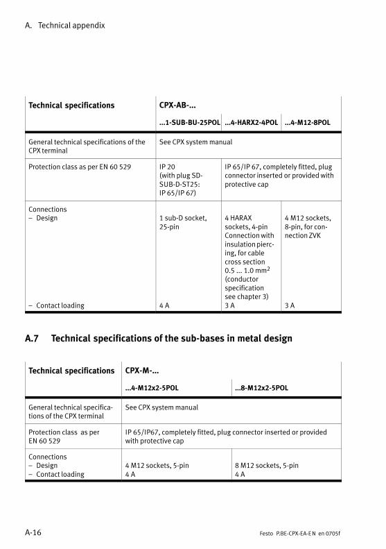
A. Technical appendix
A−16 Festo P.BE−CPX−EA−EN en 0705f
Technical specifications CPX−AB−...
...1−SUB−BU−25POL ...4−HARX2−4POL ...4−M12−8POL
General technical specifications of theCPX terminal
See CPX system manual
Protection class as per EN 60 529 IP 20(with plug SD−SUB−D−ST25:IP�65/IP 67)
IP 65/IP 67, completely fitted, plugconnector inserted or provided withprotective cap
Connections� Design
� Contact loading
1 sub−D socket,25−pin
4�A
4 HARAXsockets, 4−pinConnection withinsulation pierc�ing, for cablecross section0.5 ... 1.0 mm2
(conductor specification see chapter 3)3�A
4 M12 sockets,8−pin, for con�nection ZVK
3�A
A.7 Technical specifications of the sub−bases in metal design
Technical specifications CPX−M−...
...4−M12x2−5POL ...8−M12x2−5POL
General technical specifica�tions of the CPX terminal
See CPX system manual
Protection class as per EN 60 529
IP 65/IP67, completely fitted, plug connector inserted or providedwith protective cap
Connections� Design� Contact loading
4 M12 sockets, 5−pin4�A
8 M12 sockets, 5−pin4�A
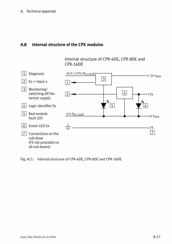
A. Technical appendix
A−17Festo P.BE−CPX−EA−EN en 0705f
A.8 Internal structure of the CPX modules
Internal structure of CPX−4DE, CPX−8DE andCPX−16DE
1 Diagnosis
2 Ex = Input x
3 Monitoring/switching off the sensor supply
4 Logic identifier Ex
5 Red modulefault LED
6 Green LED Ex
7 Connections on thesub−base(FE not provided onall sub−bases)
1
2
3
4
5
24 VSEN
Ex
0 VSEN
FE
24 V ± 25% (VEL/SEN)
0 V (VEL/SEN)
6
7
Fig.�A/1: Internal structure of CPX−4DE, CPX−8DE and CPX−16DE
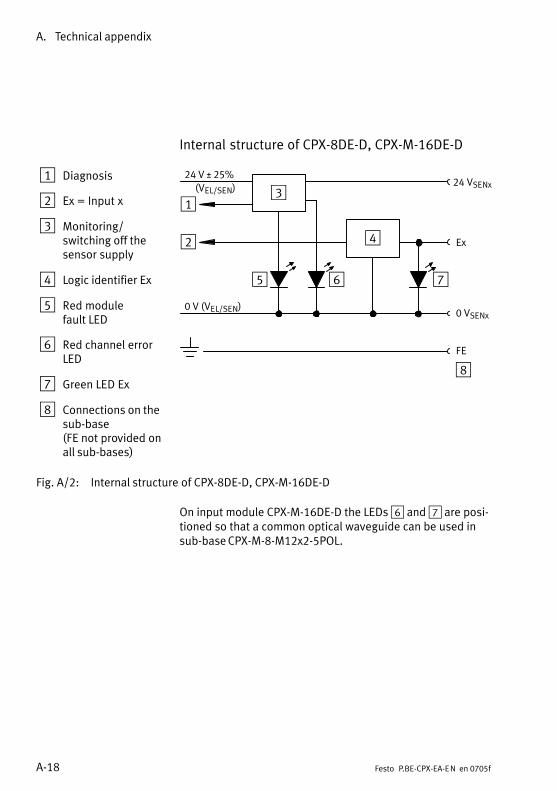
A. Technical appendix
A−18 Festo P.BE−CPX−EA−EN en 0705f
Internal structure of CPX−8DE−D, CPX−M−16DE−D
1 Diagnosis
2 Ex = Input x
3 Monitoring/switching off the sensor supply
4 Logic identifier Ex
5 Red modulefault LED
6 Red channel errorLED
7 Green LED Ex
8 Connections on thesub−base(FE not provided onall sub−bases)
24 VSENx
1
2
3
4
5
Ex
0 VSENx
FE
24 V ± 25%
0 V (VEL/SEN)
6 7
8
(VEL/SEN)
Fig.�A/2: Internal structure of CPX−8DE−D, CPX−M−16DE−D
On input module CPX−M−16DE−D the LEDs 6 and 7 are posi�tioned so that a common optical waveguide can be used insub−base CPX−M−8−M12x2−5POL.
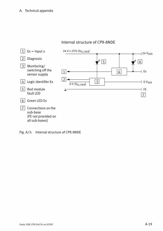
A. Technical appendix
A−19Festo P.BE−CPX−EA−EN en 0705f
Internal structure of CPX−8NDE
1 Ex = Input x
2 Diagnosis
3 Monitoring/switching off the sensor supply
4 Logic identifier Ex
5 Red modulefault LED
6 Green LED Ex
7 Connections on thesub−base(FE not provided onall sub−bases)
1
2 3
4
5
24 VSEN
Ex
0 VSEN
FE
24 V ± 25% (VEL/SEN)
0 V (VEL/SEN)
6
7
Fig.�A/3: Internal structure of CPX−8NDE
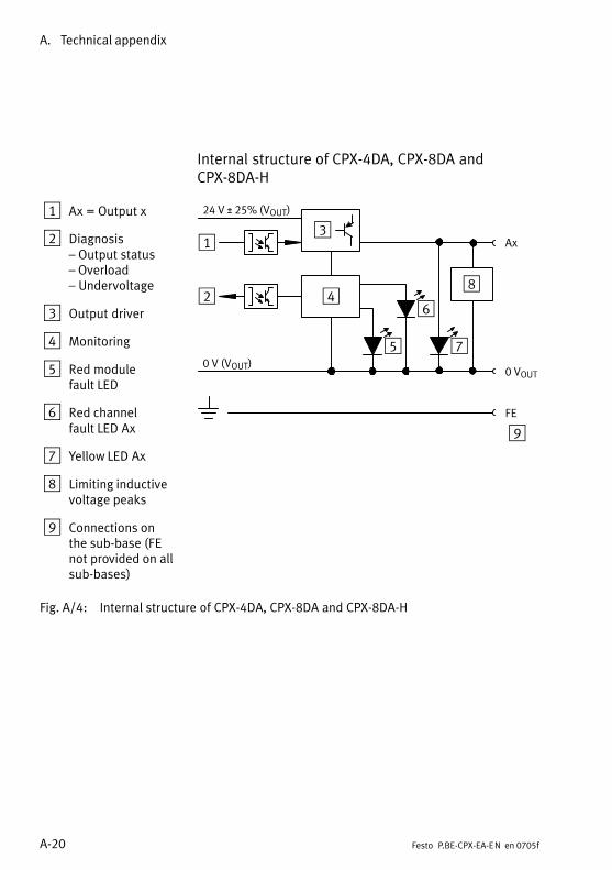
A. Technical appendix
A−20 Festo P.BE−CPX−EA−EN en 0705f
Internal structure of CPX−4DA, CPX−8DA andCPX−8DA−H
1 Ax = Output x
2 Diagnosis � Output status� Overload� Undervoltage
3 Output driver
4 Monitoring
5 Red modulefault LED
6 Red channelfault LED Ax
7 Yellow LED Ax
8 Limiting inductivevoltage peaks
9 Connections on the sub−base (FEnot provided on allsub−bases)
1
2
3
5
Ax
0 VOUT
FE
7
6
0 V (VOUT)
24 V ± 25% (VOUT)
4
9
8
Fig.�A/4: Internal structure of CPX−4DA, CPX−8DA and CPX−8DA−H
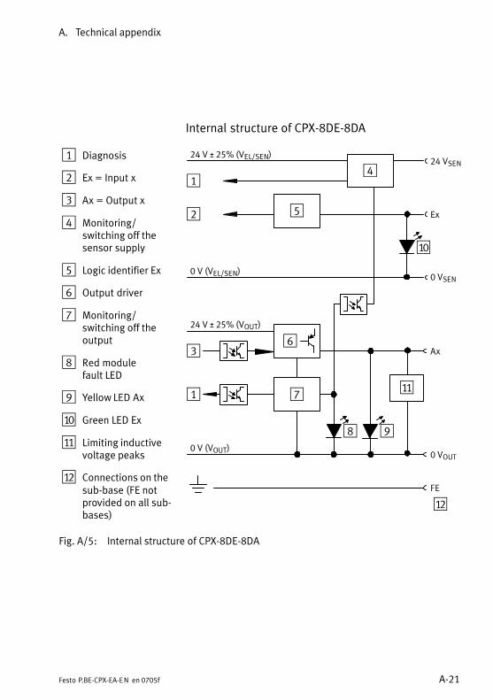
A. Technical appendix
A−21Festo P.BE−CPX−EA−EN en 0705f
Internal structure of CPX−8DE−8DA
1 Diagnosis
2 Ex = Input x
3 Ax = Output x
4 Monitoring/switching off the sensor supply
5 Logic identifier Ex
6 Output driver
7 Monitoring/switching off the output
8 Red modulefault LED
9 Yellow LED Ax
aJ Green LED Ex
aA Limiting inductivevoltage peaks
aB Connections on thesub−base (FE notprovided on all sub−bases)
1
2
3
4
5
24 VSEN
Ex
0 VSEN
24 V ± 25% (VEL/SEN)
0 V (VEL/SEN)
1
Ax
0 VOUT
FE
0 V (VOUT)
24 V ± 25% (VOUT)
6
8
7
9
aJ
aA
aB
Fig.�A/5: Internal structure of CPX−8DE−8DA
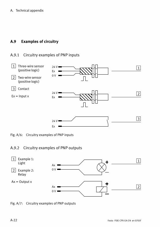
A. Technical appendix
A−22 Festo P.BE−CPX−EA−EN en 0705f
A.9 Examples of circuitry
A.9.1 Circuitry examples of PNP inputs
1 Three−wire sensor(positive logic)
2 Two−wire sensor(positive logic)
3 Contact
Ex = Input x
1ÎÎÎÎÎÎ
2
3
ÎÎÎÎÎÎ
24 V
0 V
Ex
24 V
Ex
24 V
Ex
Fig.�A/6: Circuitry examples of PNP inputs
A.9.2 Circuitry examples of PNP outputs
1 Example 1:Light
2 Example 2:Relay
Ax = Output x
1
2
0 V
Ax
Ax
0 V
Fig.�A/7: Circuitry examples of PNP outputs
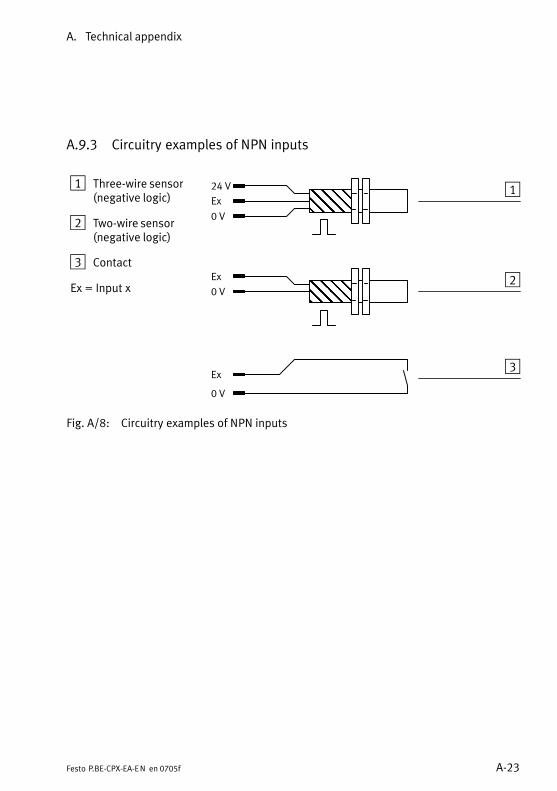
A. Technical appendix
A−23Festo P.BE−CPX−EA−EN en 0705f
A.9.3 Circuitry examples of NPN inputs
1 Three−wire sensor(negative logic)
2 Two−wire sensor(negative logic)
3 Contact
Ex = Input x
1ÎÎÎÎÎÎÎÎ
2
3
ÎÎÎÎÎÎÎÎ
24 V
0 V
Ex
Ex
0 V
Ex
0 V
Fig.�A/8: Circuitry examples of NPN inputs
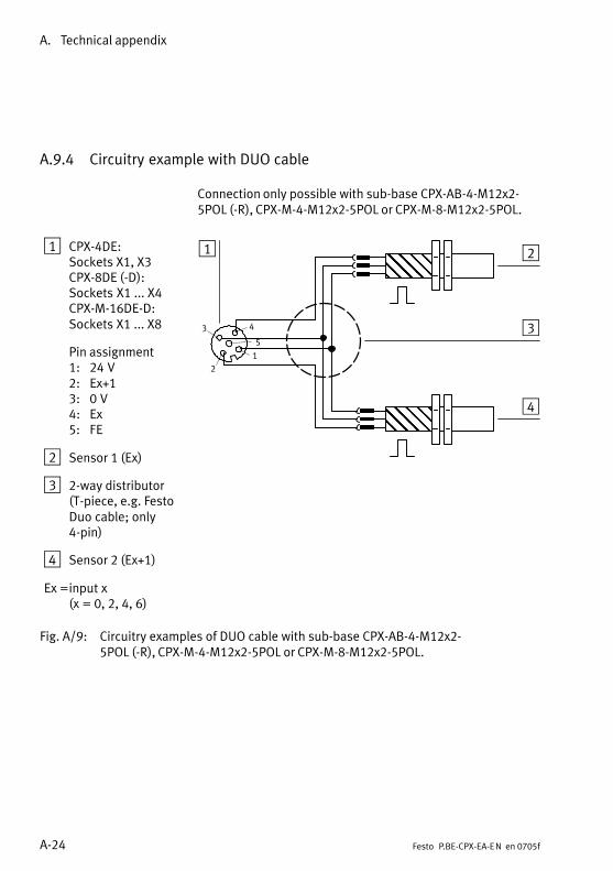
A. Technical appendix
A−24 Festo P.BE−CPX−EA−EN en 0705f
A.9.4 Circuitry example with DUO cable
Connection only possible with sub−base CPX−AB−4−M12x2−5POL�(−R), CPX−M−4−M12x2−5POL or CPX−M−8−M12x2−5POL.
1 CPX−4DE:Sockets X1, X3CPX−8DE (−D):Sockets X1�...�X4CPX−M−16DE−D:Sockets X1�...�X8
Pin assignment1: 24�V2: Ex+13: 0�V4: Ex5: FE
2 Sensor 1 (Ex)
3 2−way distributor (T−piece, e.g. FestoDuo cable; only4−pin)
4 Sensor 2 (Ex+1)
Ex =input x(x = 0, 2, 4, 6)
1 2
3
4
ÎÎÎÎÎÎÎÎ
ÎÎÎÎÎÎÎÎÎÎÎÎ
2
3
1
5
4
Fig.�A/9: Circuitry examples of DUO cable with sub−base CPX−AB−4−M12x2−5POL�(−R), CPX−M−4−M12x2−5POL or CPX−M−8−M12x2−5POL.
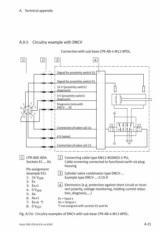
A. Technical appendix
A−25Festo P.BE−CPX−EA−EN en 0705f
A.9.5 Circuitry example with DNCV
Connection with sub−base CPX−AB−4−M12−8POL.
1 2 3 4
2
3
1
5
4
8
6
7
Signal for proximity switch S2
Signal for proximity switch S1
24 V (proximity switch/diagnosis)
0 V (proximity switch/diagnosis)
Connection of valve coil 12
Connection of valve coil 14
0 V (valve)
Diagnosis (only withDNCV−...−D)
1 CPX−8DE−8DA:Sockets X1 ... X4
Pin assignment(example X1):1: 24 VSEN2: Ex3: Ex+14: 0 VSEN5: Ax6: Ax+17: Ex+4 *)8: 0 VOUT
2 Connecting cable type KM12−8GD8GS−2−PU,Cable screening connected to functional earth via plughousing
3 Cylinder−valve combinaton type DNCV−...Example type DNCV−...−5/2J−D
4 Electronics (e.g. protection against short circuit or incor�rect polarity, voltage monitoring, holding current reduc�tion, diagnosis, ...)
Ex = Input xOx = Output x*) not assigned with sockets X3 and X4
Fig.�A/10: Circuitry examples of DNCV with sub−base CPX−AB−4−M12−8POL.
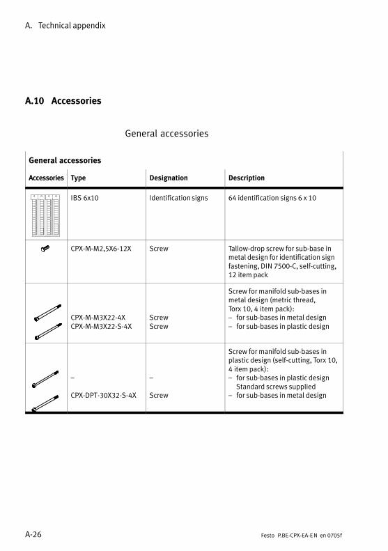
A. Technical appendix
A−26 Festo P.BE−CPX−EA−EN en 0705f
A.10 Accessories
General accessories
General accessories
Accessories Type Designation Description
IBS 6x10 Identification signs 64 identification signs 6 x 10
CPX−M−M2,5X6−12X Screw Tallow−drop screw for sub−base inmetal design for identification signfastening, DIN�7500−C, self−cutting,12�item pack
CPX−M−M3X22−4XCPX−M−M3X22−S−4X
ScrewScrew
Screw for manifold sub−bases inmetal design (metric thread,Torx�10, 4�item pack):� for sub−bases in metal design� for sub−bases in plastic design
�
CPX−DPT−30X32−S−4X
�
Screw
Screw for manifold sub−bases inplastic design (self−cutting, Torx�10,4�item pack):� for sub−bases in plastic design
Standard screws supplied� for sub−bases in metal design

A. Technical appendix
A−27Festo P.BE−CPX−EA−EN en 0705f
Accessories for sub−base CPX−AB−4−M12x2−5POL (−R)
Accessories Type Designation Description
SEA−G−S−7
SEA−4GS−7−2.5
SEA−GS−9SEA−GS−11−DUO
Sensor plug
Sensor plug
Sensor plugSensor plug
Plug, straight, M12, 4−pin, for con�necting sensors/actuators� PG7 screw connector, for cable
diameter 4 ... 6 mm� PG7 screw connector, for cable
diameter 2.5 ... 2.9 mm� PG9 screw connector� PG11 screw connector, 2 cable
exits (DUO)
SEA−M12−5GS−PG7SEA−5GS−11−DUO
PlugsSensor plug
Plug, straight, M12, 5−pin, for con�necting sensors/actuators� PG7 screw connector� PG11 screw connector
KM12−DUO−M8−GDGDKM12−DUO−M8−GDWDKM12−DUO−M8−WDWD
Duo cableDuo cableDuo cable
Duo cable with M8 plugs:� straight/straight� straight/angled� angled/angled
KM12−M12−GSGD−2.5KM12−M12−GSGD−5.0KM12−M12−GSWD−1−4
Connecting cableConnecting cableConnecting cable
Extension cable for Duo cable� Length 2.5 m, straight/straight� Length 5.0 m, straight/straight� Length 1.0 m, straight/angled
NEBU−... Modular kit for con�necting cables
Connecting cables of variouslengths and designs for M8 andM12 connections (as from 2005)
CPX−AB−S−4−M12 Screening plate Screening plate for improvingEMC compatibilityA blade connector as perDIN�46�245 or DIN 46�247 B2,8−1(2.8 x 1 mm) is also required forconnecting the functional earth(FE).
ISK−M12 Protective cap Protective cap for sealing unusedconnector sockets
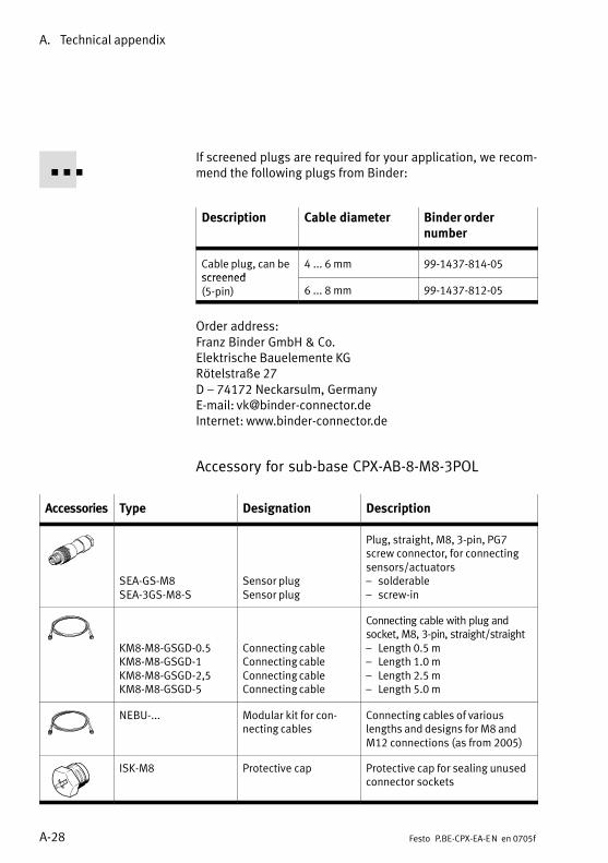
A. Technical appendix
A−28 Festo P.BE−CPX−EA−EN en 0705f
If screened plugs are required for your application, we recom�mend the following plugs from Binder:
Description Cable diameter Binder ordernumber
Cable plug, can bescreened
4 ... 6 mm 99−1437−814−05screened(5−pin) 6 ... 8 mm 99−1437−812−05
Order address:Franz Binder GmbH & Co.Elektrische Bauelemente KGRötelstraße 27D � 74172 Neckarsulm, GermanyE−mail: vk@binder−connector.deInternet: www.binder−connector.de
Accessory for sub−base CPX−AB−8−M8−3POL
Accessories Type Designation Description
SEA−GS−M8SEA−3GS−M8−S
Sensor plugSensor plug
Plug, straight, M8, 3−pin, PG7screw connector, for connectingsensors/actuators� solderable� screw−in
KM8−M8−GSGD−0.5KM8−M8−GSGD−1KM8−M8−GSGD−2,5KM8−M8−GSGD−5
Connecting cableConnecting cableConnecting cableConnecting cable
Connecting cable with plug andsocket, M8, 3−pin, straight/straight� Length 0.5 m� Length 1.0 m� Length 2.5 m� Length 5.0 m
NEBU−... Modular kit for con�necting cables
Connecting cables of variouslengths and designs for M8 andM12 connections (as from 2005)
ISK−M8 Protective cap Protective cap for sealing unusedconnector sockets
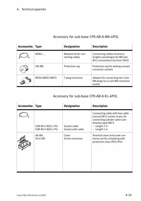
A. Technical appendix
A−29Festo P.BE−CPX−EA−EN en 0705f
Accessory for sub−base CPX−AB−8−M8−4POL
Accessories Type Designation Description
NEBU−... Modular kit for con�necting cables
Connecting cables of variouslengths and designs for M8 andM12 connections (as from 2005)
ISK−M8 Protective cap Protective cap for sealing unusedconnector sockets
NEDU−M8D3−M8T4 T−plug connector Adapter for connecting two 3−pinM8 plugs to a 4−pin M8 connectorsocket
Accessory for sub−base CPX−AB−8−KL−4POL
Accessories Type Designation Description
SIM−M12−8GD−2−PUSIM−M12−8GD−5−PU
Socket cableSocket with cable
Connecting cable with free cableend and M12 socket, 8−pin, forconnecting cylinder−valve com�bination type DNCV� Length 2 m� Length 5 m
AK−8KLVG−K−M9
CoverScrew connector
Terminal cover and screw con�nector set for complying withprotection class IP65/IP67.
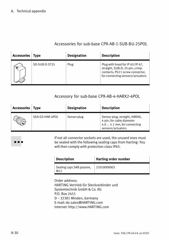
A. Technical appendix
A−30 Festo P.BE−CPX−EA−EN en 0705f
Accessories for sub−base CPX−AB−1−SUB−BU−25POL
Accessories Type Designation Description
SD−SUB−D−ST25 Plug Plug with hood for IP 65/IP 67,straight, SUB−D, 25−pin, crimpcontacts, PG11 screw connector,for connecting sensors/actuators
Accessory for sub−base CPX−AB−4−HARX2−4POL
Accessories Type Designation Description
SEA−GS−HAR−4POL Sensor plug Sensor plug, straight, HARAX,4−pin, for cable diameter4.0�...�5.1�mm, for connecting sensors/actuators
If not all connector sockets are used, the unused ones mustbe sealed with the following sealing caps from Harting: Youwill then comply with protection class IP65.
Description Harting order number
Sealing caps SAB passive,M12
21010000003
Order address:HARTING Vertrieb für Steckverbinder undSystemtechnik GmbH & Co. KGP.O. Box 2451D � 32381 Minden, GermanyE−mail: [email protected]: http://www.HARTING.com
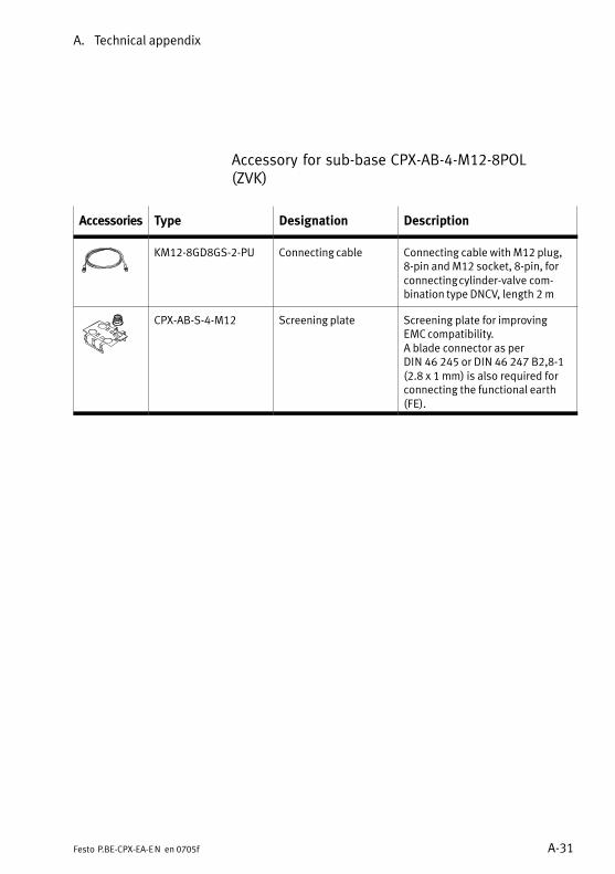
A. Technical appendix
A−31Festo P.BE−CPX−EA−EN en 0705f
Accessory for sub−base CPX−AB−4−M12−8POL(ZVK)
Accessories Type Designation Description
KM12−8GD8GS−2−PU Connecting cable Connecting cable with M12 plug,8−pin and M12 socket, 8−pin, forconnecting cylinder−valve com�bination type DNCV, length 2 m
CPX−AB−S−4−M12 Screening plate Screening plate for improvingEMC compatibility.A blade connector as perDIN�46�245 or DIN 46�247 B2,8−1(2.8 x 1 mm) is also required forconnecting the functional earth(FE).
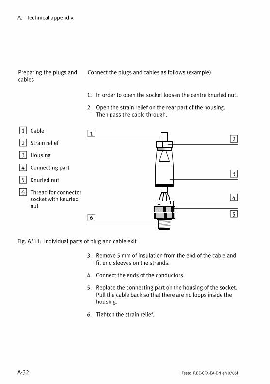
A. Technical appendix
A−32 Festo P.BE−CPX−EA−EN en 0705f
Preparing the plugs andcables
Connect the plugs and cables as follows (example):
1. In order to open the socket loosen the centre knurled nut.
2. Open the strain relief on the rear part of the housing.Then pass the cable through.
1 Cable
2 Strain relief
3 Housing
4 Connecting part
5 Knurled nut
6 Thread for connectorsocket with knurlednut
12
3
4
56
Fig.�A/11: Individual parts of plug and cable exit
3. Remove 5 mm of insulation from the end of the cable andfit end sleeves on the strands.
4. Connect the ends of the conductors.
5. Replace the connecting part on the housing of the socket.Pull the cable back so that there are no loops inside thehousing.
6. Tighten the strain relief.

Index
B−1Festo P.BE−CPX−EA−EN en 0705f
Appendix B
B. Index
B−2 Festo P.BE−CPX−EA−EN en 0705f
Contents
B. Index B−1 . . . . . . . . . . . . . . . . . . . . . . . . . . . . . . . . . . . . . . . . . . . . . . . . . . . . . . . . .
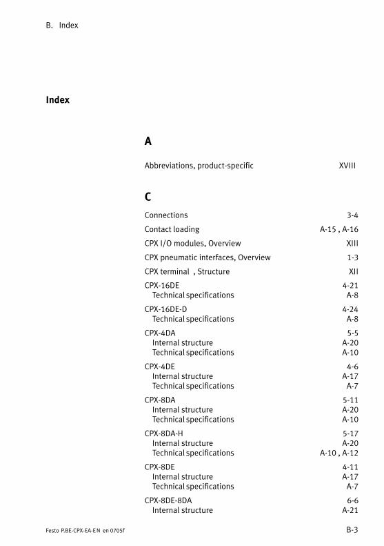
B. Index
B−3Festo P.BE−CPX−EA−EN en 0705f
Index
A
Abbreviations, product−specific XVIII
C
Connections 3−4
Contact loading A−15 , A−16
CPX I/O modules, Overview XIII
CPX pneumatic interfaces, Overview 1−3
CPX terminal , Structure XII
CPX−16DE 4−21 Technical specifications A−8
CPX−16DE−D 4−24 Technical specifications A−8
CPX−4DA 5−5 Internal structure A−20 Technical specifications A−10
CPX−4DE 4−6 Internal structure A−17 Technical specifications A−7
CPX−8DA 5−11 Internal structure A−20 Technical specifications A−10
CPX−8DA−H 5−17 Internal structure A−20 Technical specifications A−10 , A−12
CPX−8DE 4−11 Internal structure A−17 Technical specifications A−7
CPX−8DE−8DA 6−6 Internal structure A−21
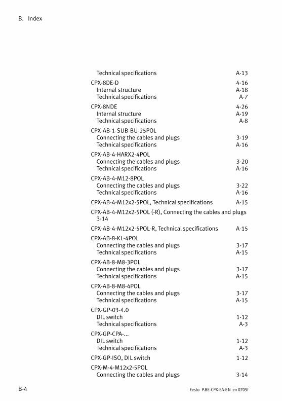
B. Index
B−4 Festo P.BE−CPX−EA−EN en 0705f
Technical specifications A−13
CPX−8DE−D 4−16 Internal structure A−18 Technical specifications A−7
CPX−8NDE 4−26 Internal structure A−19 Technical specifications A−8
CPX−AB−1−SUB−BU−25POLConnecting the cables and plugs 3−19 Technical specifications A−16
CPX−AB−4−HARX2−4POLConnecting the cables and plugs 3−20 Technical specifications A−16
CPX−AB−4−M12−8POLConnecting the cables and plugs 3−22 Technical specifications A−16
CPX−AB−4−M12x2−5POL, Technical specifications A−15
CPX−AB−4−M12x2−5POL (−R), Connecting the cables and plugs3−14
CPX−AB−4−M12x2−5POL−R, Technical specifications A−15
CPX−AB−8−KL−4POLConnecting the cables and plugs 3−17 Technical specifications A−15
CPX−AB−8−M8−3POLConnecting the cables and plugs 3−17 Technical specifications A−15
CPX−AB−8−M8−4POLConnecting the cables and plugs 3−17 Technical specifications A−15
CPX−GP−03−4.0DIL switch 1−12 Technical specifications A−3
CPX−GP−CPA−...DIL switch 1−12 Technical specifications A−3
CPX−GP−ISO, DIL switch 1−12
CPX−M−4−M12x2−5POLConnecting the cables and plugs 3−14
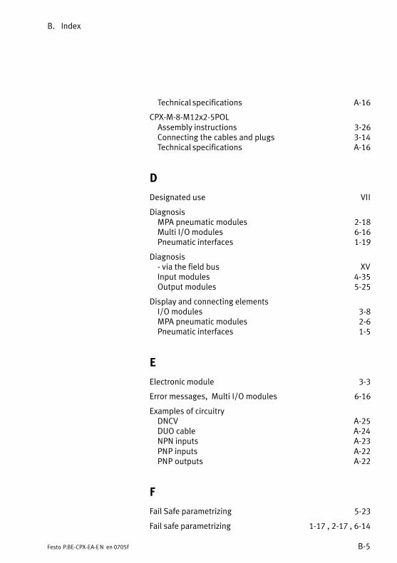
B. Index
B−5Festo P.BE−CPX−EA−EN en 0705f
Technical specifications A−16
CPX−M−8−M12x2−5POLAssembly instructions 3−26 Connecting the cables and plugs 3−14 Technical specifications A−16
D
Designated use VII
DiagnosisMPA pneumatic modules 2−18 Multi I/O modules 6−16 Pneumatic interfaces 1−19
Diagnosis− via the field bus XV Input modules 4−35 Output modules 5−25
Display and connecting elementsI/O modules 3−8 MPA pneumatic modules 2−6 Pneumatic interfaces 1−5
E
Electronic module 3−3
Error messages, Multi I/O modules 6−16
Examples of circuitryDNCV A−25 DUO cable A−24 NPN inputs A−23 PNP inputs A−22 PNP outputs A−22
F
Fail Safe parametrizing 5−23
Fail safe parametrizing 1−17 , 2−17 , 6−14
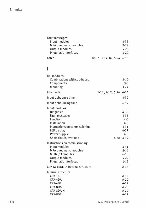
B. Index
B−6 Festo P.BE−CPX−EA−EN en 0705f
Fault messagesInput modules 4−35 MPA pneumatic modules 2−22 Output modules 5−26 Pneumatic interfaces 1−20
Force 1−18 , 2−17 , 4−34 , 5−24 , 6−15
I
I/O modulesCombinations with sub−bases 3−10 Components 3−3 Mounting 3−24
Idle mode 1−18 , 2−17 , 5−24 , 6−14
Input debounce time 4−32
Input debouncing time 6−12
Input modulesDiagnosis 4−35 Fault messages 4−35 Function 4−3 Installation 4−5 Instructions on commissioning 4−31 LED display 4−37 Power supply 4−5 Short circuit/overload 4−38 , 4−39
Instructions on commissioningInput modules 4−31 MPA pneumatic modules 2−16 Multi I/O modules 6−10 Output modules 5−22 Pneumatic interfaces 1−15
CPX−M−16DE−D, Internal structure A−18
Internal structureCPX−16DE A−17 CPX−4DA A−20 CPX−4DE A−17 CPX−8DA A−20 CPX−8DA−H A−20 CPX−8DE A−17
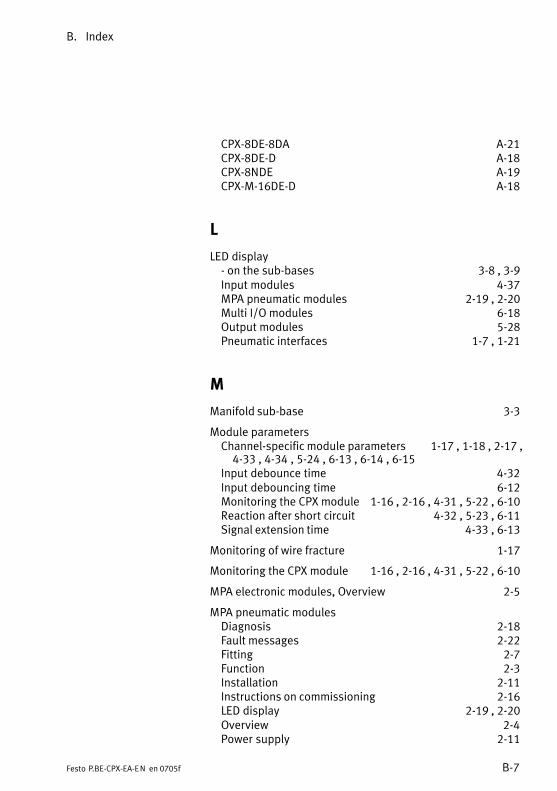
B. Index
B−7Festo P.BE−CPX−EA−EN en 0705f
CPX−8DE−8DA A−21 CPX−8DE−D A−18 CPX−8NDE A−19 CPX−M−16DE−D A−18
L
LED display− on the sub−bases 3−8 , 3−9 Input modules 4−37 MPA pneumatic modules 2−19 , 2−20 Multi I/O modules 6−18 Output modules 5−28 Pneumatic interfaces 1−7 , 1−21
M
Manifold sub−base 3−3
Module parametersChannel−specific module parameters 1−17 , 1−18 , 2−17 ,4−33 , 4−34 , 5−24 , 6−13 , 6−14 , 6−15
Input debounce time 4−32 Input debouncing time 6−12 Monitoring the CPX module 1−16 , 2−16 , 4−31 , 5−22 , 6−10 Reaction after short circuit 4−32 , 5−23 , 6−11 Signal extension time 4−33 , 6−13
Monitoring of wire fracture 1−17
Monitoring the CPX module 1−16 , 2−16 , 4−31 , 5−22 , 6−10
MPA electronic modules, Overview 2−5
MPA pneumatic modulesDiagnosis 2−18 Fault messages 2−22 Fitting 2−7 Function 2−3 Installation 2−11 Instructions on commissioning 2−16 LED display 2−19 , 2−20 Overview 2−4 Power supply 2−11
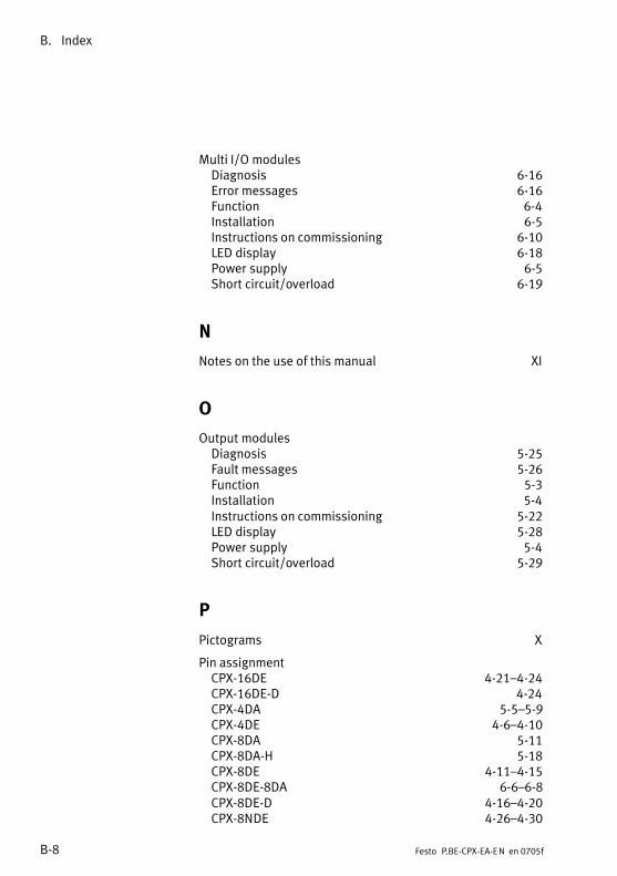
B. Index
B−8 Festo P.BE−CPX−EA−EN en 0705f
Multi I/O modulesDiagnosis 6−16 Error messages 6−16 Function 6−4 Installation 6−5 Instructions on commissioning 6−10 LED display 6−18 Power supply 6−5 Short circuit/overload 6−19
N
Notes on the use of this manual XI
O
Output modulesDiagnosis 5−25 Fault messages 5−26 Function 5−3 Installation 5−4 Instructions on commissioning 5−22 LED display 5−28 Power supply 5−4 Short circuit/overload 5−29
P
Pictograms X
Pin assignmentCPX−16DE 4−21�4−24 CPX−16DE−D 4−24 CPX−4DA 5−5�5−9 CPX−4DE 4−6�4−10 CPX−8DA 5−11 CPX−8DA−H 5−18 CPX−8DE 4−11�4−15 CPX−8DE−8DA 6−6�6−8 CPX−8DE−D 4−16�4−20 CPX−8NDE 4−26�4−30

B. Index
B−9Festo P.BE−CPX−EA−EN en 0705f
Pneumatic interfacesDiagnosis 1−19 DIL switch 1−9 Fault messages 1−20 Fitting 1−8 Function 1−3 Installation 1−14 Instructions on commissioning 1−15 LED display 1−21 Power supply 1−14
Power supply 1−14 , 2−11 , 4−5 , 5−4 , 6−5
Protection class 3−19 , A−3�A−14 , A−15 , A−16
R
Reaction after short circuit 4−32 , 5−23 , 6−11
S
Screening/shield plate− connect 3−15 , 3−22 − fitting 3−28
Service VIII
Short circuit/overload 4−38 , 4−39 , 5−29 , 6−19 CPX−8DA−H, A−12
Signal extension time 4−33 , 6−13
Sub−basesCombinations with I/O modules 3−10 Connecting the cables and plugs 3−13 Metal design 3−7 , 3−9 , 3−12 Overview 3−3 , 3−4
T
Target group VIII
Technical specificationsInput modules A−7
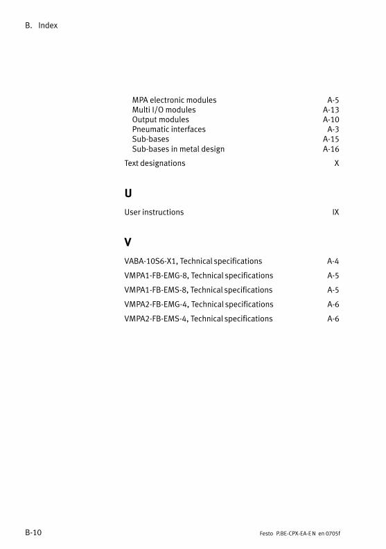
B. Index
B−10 Festo P.BE−CPX−EA−EN en 0705f
MPA electronic modules A−5 Multi I/O modules A−13 Output modules A−10 Pneumatic interfaces A−3 Sub−bases A−15 Sub−bases in metal design A−16
Text designations X
U
User instructions IX
V
VABA−10S6−X1, Technical specifications A−4
VMPA1−FB−EMG−8, Technical specifications A−5
VMPA1−FB−EMS−8, Technical specifications A−5
VMPA2−FB−EMG−4, Technical specifications A−6
VMPA2−FB−EMS−4, Technical specifications A−6