cpm booster card - axemotionaxemotion.com/includes/languages/english/doc/imc4booster... · card is...
TRANSCRIPT

CPM Booster CardRetrofit card for Isel IMC4 controllers.
User’s Guide

CPM Booster manual
2

CPM Booster manual
3
CPM Booster Card
User’s Guide
Version 1.0
Januari 2010
Retrofit card for Isel IMC4 controllers.
Hardware: Copyright © 2008-2010 AxeMotionSoftware: Copyright © 2008-2010 Bertrand Lenoir-WelterManual: Copyright © 2008-2010 Delft Spline Systems
All rights reserved.

CPM Booster manual
4

CPM Booster manual
5
CONTENTS
1 THE BOOSTER CARD 7
2 HARDWARE SETUP 8
3 SOFTWARE SETUP 10
4 OPERATION 12
Appendix A, Detail settings 13
Appendix B, Specifications 16

CPM Booster manual
6

CPM Booster manual
7
CHAPTER 1: THE BOOSTER CARD
The CPM machine is one of the most successful machines made by German manufacturer Isel. The machinefeatures a closed cabinet built of metal, which is a stable frame for the machine and guarantees a safe operationas milling is possible only with the door closed. The CPM series are based on the IMC4 stepper motor controller:a proven design with a track record that shows a great reliability.
Drawback of this IMC4 controller is that it is not a very fast controller:between every two movements the cutter will briefly stop. So at the end of a movement the machine willdecelerate, stop for a moment and then again accelerate for the next movement. As a result the machine movesrather jerky when executing series of G1 movements (linear interpolations).This jerky movement style comes with a few serious disadvantages:- It takes a lot of time. Especially when the movements are short: then the machine does not even come close tothe nominal feedrate as it is decelerating and accelerating all the time.- The resulting surface quality is not very good- Machining metals is not possible.Second drawback of the IMC4 is that communication with the PC a serial cable is used (RS232). This is a ratherobsolete method: most current PCs no longer have a serial port present. For communication with the PC currentdevices us USB.
Stepper motor control has evolved a lot since the IMC4 controller was designed: fluid movements and a machinethat keeps up speed are very well possible nowadays.Axemotion is a specialist in controlling stepper motor based machines. Based on this knowhow, Axemotion hasdeveloped an plug-in card for the IMC-4 controller that changes it to an up-to-date stepper motor controller. Thiscard is called the CPM Booster card, and you new are reading the manual for this card.
The CPM Booster card features:- USB Interface- up to 4 axes controlled simultaneously- look-ahead buffer (250 vectors).- supports all IMC4 functionality
The Booster card will not function with the Isel Remote or RemoteWin software: it needs to use Kay or Galaadas control software. This is because the software must be able to do the inverse kinematics: analyze themovements and determine the optimum speeds at each moment.
Installing this card will save a lot of time for NC files with loads of very small G1 movements. Reducing timewith 50% is easily possible, in many cases the time gain will even be higher !An extreme example was a 8 Mb NCP file for a small object (jewelry, ca 40x50x10 mm). Very accuratetoolpaths with G1 movements only: small distance between the toolpaths and small stepsize. A conical cutterwith a 0.1 mm tip was used. Here the difference between the original IMC4 and the Axemotion booster wasenormous:- IMC4 242 minutes (so 4 hours 2 min)- AxeMotion 40 minutesSo a milling time reduction of over 80 % !!!
Check the videos on www.spline.nl to see the different movement style.
For NC files with long movements (say G1 movements of 20 or more mm long no time gain will be present: thenalso with the original IMC4 the machine will be on speed most of the time. And the maximum speed (60 mm secfor CPM machines with a 10 mm ballscrew pitch) is caused by the maximum rotation speed of the stepper motorsand cannot be improved.

CPM Booster manual
8
CHAPTER 2: HARDWARE SETUP
How to insert the IMC4 Booster card into the IMC4 controller.
The IMC4 controller is located on the back side of your Isel CPM or ICP machine. You can see it after removingthe back cover panel of the machine (six hexagon screws). Note that this panel is connected to the machine by anearth wire.In order to insert the AxeMotion Booster card you also need to remove the back panel of the controller (threePhillips screws and some double sided tape). Carefully remove this panel in order not to damage the cable thatconnects the ventilator in the panel to the controller (you can disconnect the plug to completely loosen the panel).
Now you can see the PCB board of the IMC4 controller, as shown in the picture above.From this controller you need to remove 7 chips: 2 square PLCs and 5 rectangular chips. Note that for removingthe PLCs you need a tool called “PLCC extractor”. For the chips using a chip extractor is advised as well: whenyou correctly remove them (without bending the pins) you will be able to replace them later if needed. Makenotes which chip was placed in which connector, and how it was orientated.
The picture above show the 7 chips removed, indicated by 7 red circles.You can also see 3 blue circles: the IMC4 Booster card needs to be pressed into these three chip connectors. To

CPM Booster manual
9
make this possible the booster card comes with some extra connectors to bridge the distance between the twoboards.
Placing the board will prove to be the most difficult part of the complete installation procedure: normally whenpressing one chip down it is possible to gently rock the chip while pressing in order to make it slide home. Ashere three connectors are present this is not possible. And in addition it is not possible to see what you are doingas the Booster card completely blocks your view.
Check carefully if the pins of the two 32 pins (2x16) connectors are all well placed on the two 32 pins sockets ofthe IMC4. If that is OK you can firmly press on the "middle" of each these two connectors. All pins must becompletely inserted into the socket. After that, the PLCC connector will slide into position when pressing thatpart of the booster board.
As a result all pins should have been completely inserted, and the Booster card needs to be exactly parallel to theIMC4 main board. The booster board also may not be bended. In case this plugging in has not been done completely correct you will get unpredictable behavior. In the pictureabove you can see a card that has NOT yet been fully plugged in (note that your booster card may have adifferent color).
Finally you can plug a standard USB cable into the IMC4 Booster board and lead that to the outside of themachine. Or you can mount a USB connector in the back wall of your machine, next to the other connectors.Connect the booster card with the inside of that connector using a short USB cable: you now can close themachine and use a second USB cable to connect PC to machine.
CPM Booster manual
10
CHAPTER 3: SOFTWARE SETUP
2.1 How to install the Drivers for the Booster Card.
Do NOT use a Win95, Win98 or Win ME based PC for this card: the USB system on these PCs is too old andyou will run into problems when using the Booster card. Use Win 2000, XP, Vista or newer.
The IMC4 Booster Card makes your milling machine a USB device, so you will need USB drivers in order to useit. Unfortunately these drivers do not yet come with a Setup program: you need to manually install them.You can download the driver files from http://www.axemotion.com (Download menu) There you can find a file called “AxMo 2-n.nn.nn.zip ” where n.nn.nn is the version number. Must be 2.02.04 ornewer. Unpack this file and remember into which directory.
Next, when you connect the USB cable from the Booster board to your PC, Windows will start the NewHardware found wizard. Make this wizard look in the directory just mentioned and use the driver it will findthere. It might be that this needs to be done twice as the driver comes in two parts.
2.2 How to configure Kay to work with the Booster Card.
Your Isel machine has been delivered with a Kay CD. As a first step you will need to install Kay from this CD:later updates will only work when a valid Kay license is present already.
Next you need to download and install such update, as the version on your CD may not yet support the boostercard. For downloading please visit www.galaad.net Go to the Download page and download an “Update formain modules” in your preferred language. Unpack this ZIP file into the directory of your original Kayinstallation, which by default will be C:\Program Files\Galaad\Just over-write the old files with the new versions.
Now you are ready to start.In contrast to how the machine behaved earlier, you cannot yet press the green Power button on the front of yourmachine to power up the IMC4 controller: Kay will tell you when this can be done.
Start Kay, cancel the file load (or load a small NC file) and open the Machine Parameters (Parameters menu,Machine ...). It might be that these will be opened automatically when Kay cannot find the currently selectedmachine (Note that the dialog is called “Mill parameters”).
It may be that in a moment you will see a message that Kay is automatically updating the firmware of the CNCCard. That is OK: as the software changes more often than the hardware this is way to keep them both up-to-date.

CPM Booster manual
11
The first tab of this dialog is called Table and is shown above left.Here select your machine: make sure to choose the type with “/ AxeMotion” added to the original name.You also need to check the values for the ballscrew pitch: most CPM machines have 10 mm per revolution, itmight be that Kay incorrectly sets these to 4. If so then you need to change 4 to 10 for all three axes.Motor Steps needs to be 1600 for all three axes (detailed information: the Isel stepper motors have 200 steps,however are operated using a 1/8 step microstep resolution which results in 1600 steps).
The second tab page is called Controller, as shown above right, and the settings should be correct automatically:Controller type is AxeMotion IMC-Plugin and Port is USB. Now press the button “More” just right of the controller type IMC-Plugin.
The AxeMotion sub-dialog shown above will pop up.Important here is to check the option “Update CNC card firmware automatically”. This is a great option, as itallows you to renew the firmware on your booster card. Downloading new software is easier than ordering a newcard, so it is an easy way to keep your card updated. It is important to check this option as your card may havebeen in stock for some time and thus may have old firmware.
All other settings in this dialog should be automatically correct. When you want to know more you can check theappendix of this manual.

CPM Booster manual
12
CHAPTER 4: OPERATION
Using the machine:
When you have completed all steps of the Setup as described in the previous chapters, you are ready to use youroptimized machine. You can use Kay just as before (see the Kay manual).The only difference when starting is that you now need to first start Kay and only when Kay asks you press thegreen Power button of your CPM machine.
When using Kay, two more difference can be observed now the booster card has been installed, and these twodifferences are in fact disadvantages.
Previously the movement information was sent to the machine line by line: so only after completing a movementthe next command was sent over (while the machine briefly halted). Because of this Kay always knew the currentposition of the cutter, and could update the drawing to exactly follow the real cutter.Now the movement information is sent to the booster card in large chunks, which is needed in order to keep upspeed. So Kay no longer knows the position of the cutter at any given moment, so the drawing no longer issynchronized with the cutter movement. The booster card also allows sending over data while the machine ismilling. Previously the IMC4 could either communicate or machine.
The second change is while interrupting the program: Previously is was possible to press the red stop button onthe Kay screen at any moment, briefly stop (say to remove the chips) and the continue on the same location. AsKay no longer knows the exact position this is no longer possible.Stopping at any moment still works (using the red stop button), however when resuming the cutter will restart atthe last rapid movement. This might even be the begin of the NC file. This is needed as kinematics calculationsfor all moves are now related: the instant speed when stopping was the result of all previous vectors with theirown calculated speeds. So, the only possibility is resume at the last tool-down position, so to make a fresh startafter the last Rapid move.This is a disadvantage indeed, we hope that it will be possible to find a way to improve this situation.
The Pause button on the Kay screen will not properly function either: the movement will indeed be paused,however Kay will wait until the next Rapid movement before Pausing, which may take very long.
Still we feel that the advantages clearly outweigh these two problems, and as you know about them you can learnhow to dal with them.
Please note that kinematics calculation in Kay does not consider the rotary axes. So the toolpaths should be inXYZ, with increments of A in-between. If you use A axis for the active milling motion, then the kinematics isnot integrated and you may lose steps if there are frequency gaps. This is a limit of Kay module which has beenembedded the kinematics function though its data storage architecture was not made for it. This will be removedin Galaad 4 where all milling modules, i.e. Lancelot and Kay, will be merged in one single program will all themotion and I/O functions present.
Once you start machining you will immediately hear the difference: instead of the low rumbling noise that madeboth machine and table vibrate, while machining you will now hear music !Machining time will be much lower for accurate NC files, that is for files with many small movements.
CPM Booster manual
13
APPENDIX A: Detail settingsFor the kinematics calculations done in Kay or Galaad many detail settings can be made. These settings shouldbe OK on installation, still it may be needed for you to have some background information.
The AxeMotion cards allow Kay/Galaad to calculate an optimal feedrate for each vector: begin & end ramps arenot made if not needed. The calculation is quite complicated and tries to make the machine move as fast aspossible (theoretical feedrate being a ceiling) without losing steps, i.e. without making frequency jumps that theinertia of motors & axes could not allow. So new vectors are added to build artificial acceleration anddeceleration stairs where needed (in case of big frequency jumps). So the actual number of vectors may be easilymultiplied by 10 or 20 if the path contains many sharp angles or small curves.
As just said, the purpose of the kinematics algorithm is to go as fast as possible with not a chance to have lossesof steps. That point is very important. Of course, if you use a machine that has more powerful motors or lessinertia, then you can increase all kinematics parameters and consequently the actual machining time can bereduced a lot. If the kinematics parameters are correct it should be impossible to go faster without loosing steps.The CPM machine has high-torque motors that unfortunately cannot turn fast (and this is why they fit themachine with 10 mm ballscrews), and their torque decreases a lot with speed, which ceilings the jump speed.Furthermore the axes of the machine are somewhat heavy. This is a good warranty for less vibrations whenmilling metal, but it requires much torque to make axes accelerate and decelerate. These machine characteristicsset the maximum speed and acceleration that can be achieved.
The kinematics settings in Kay can be found in two different dialogs.
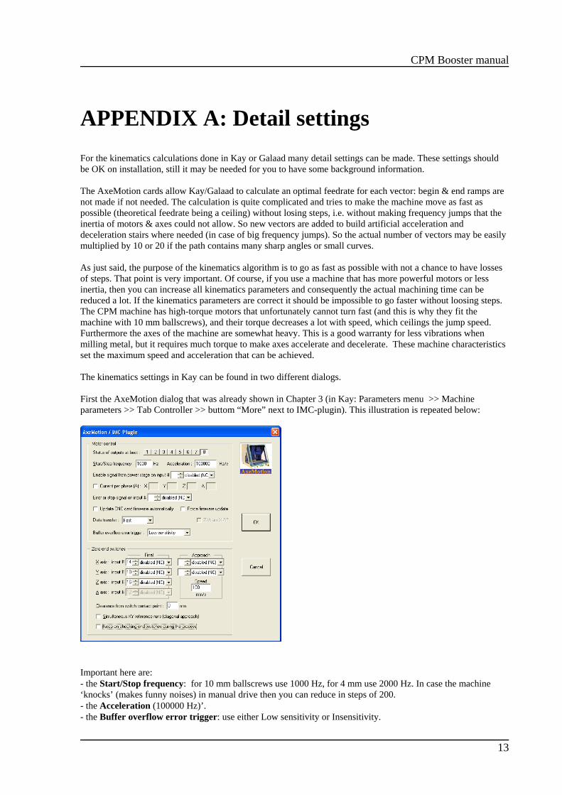
First the AxeMotion dialog that was already shown in Chapter 3 (in Kay: Parameters menu >> Machineparameters >> Tab Controller >> buttom “More” next to IMC-plugin). This illustration is repeated below:
Important here are:- the Start/Stop frequency: for 10 mm ballscrews use 1000 Hz, for 4 mm use 2000 Hz. In case the machine‘knocks’ (makes funny noises) in manual drive then you can reduce in steps of 200.- the Acceleration (100000 Hz)’.- the Buffer overflow error trigger: use either Low sensitivity or Insensitivity.

CPM Booster manual
14
In case the Acceleration frequency is too high this may result in losing steps during high load conditions, youthen can try reducing to 75000 or even 50000.
As said in Chapter 3: Check the option “Update CNC card firmware automatically”
The second dialog with booster card settings is about the kinematical post calculation, shown below right.You can find it via the fifth tab of the machine parameters: Advanced, as shown below left. You can call theextra dialog by enabling the checkbox “Enable kinematics calculation”. When it is already enabled then firstdeselect and then again enable: then the dialog with kinematics settings will pop up.
Here you see the same two frequencies as just discussed, and in addition the:kinematic jump speed (now 4 mm/sec) ?? Should be 8 mm/sec ?kinematic acceleration (now 80 mm / sec2)Anti-overflow optimization (now 1)
The kinematics parameters are divided in two groups. At top, the Start/Stop frequency and the acceleration aresuitable only for vectors with acceleration/deceleration ramps. These are easy to setup and I assume defaultvalues should be ok. The best test is the manual drive. If you hear the machine knock when a motor starts orstops moving, then the Start/Stop frequency is too high. The machine is light and the motor have much torque, sothis frequency can be rather high. Start/Stop frequency actually represents the instant gap between still andmoving, because a motor motion does not need to start and stop from zero. Furthermore, stepper motors havetheir maximum torque at low speed, so they can skip instantly to that turning frequency. I usually set this to 1/2revolution per second, i.e. 800 Hz in that case. The Acceleration is the leading factor of the speed slope, startingfrom the above-mentioned frequency and until the demanded speed is reached. If too high, the motors whistleand refuse to turn. If too low, the machine looks heavy with soft accelerations. Again, the manual drive saysmore. When the motors refuse to turn, divide the value roughly by 2.
At bottom, the other kinematics parameters are used for Kay/Galaad calculation of the active path. Kay willconsider the speed as a target, that can be reached only whenever possible. The purpose is to avoid a too largegap of frequency for a motor between two consecutive vectors, which would induce a loss of steps. Hence Kaytries to keep the speed as close as possible to the demanded speed, but when a motor makes a big jump offrequency, then it must have intermediate stairs of speed to pass the change. This induces kind of domino fallbecause the interpolated stairs may also change the other vectors before and after. Believe me the algorithm isextremely complicated and required several month development. The Jump speed values indicate the maximum speed jump that a motor can perform without losing steps, inmetric speed because axes may have different gear factors, and the Global slope of the acceleration &deceleration stairs. If a milling path knocks, then the jumping speed should be decreased. If the small curves arepassed too slowly, then the acceleration slope should be increased.

CPM Booster manual
15
Conclusion: if you lose steps in manual drive, then reduce the Start/Stop frequency and possibly the topacceleration. If you lose steps during the milling process, then reduce the jump and slope values. If the machineis making hatched motion in a path that contains many small vectors, that means the card buffer gets emptybecause the milling process runs faster than the USB transmission. I'm afraid there is nothing to do in that caseexcept reduce the milling speed.
For the Anti-overflow parameter the default value is 1. It indicates the priority of the speed compared to theaccuracy, i.e. very small vectors that are not significant in the path can be ignored when moving very fast. If you have toolpath with many small vectors and you do not need 0.01 mm accuracy, then set that value to 3,even 4. If increased, Kay/Galaad will ignore small vectors which do not change much the motion direction. Thegoal is to reduce the number of vectors that have to be sent to the machine, because the transmission is thebottleneck for the data flow. The removal of small vectors is made considering their length, their directionchange and the feed speed. If the speed is high, Galaad will ignore more significant vectors. If it is slow, then novectors will be ignored. Anyway the vectors that are ignored cannot be longer than 1 mm and cannot make adirection change of more than 5°. This function is a filter for eliminating insignificant vectors that would floodthe transmission.
Below more detailed information about the kinematics calculations:
The best comparison for kinematics in a machine tool could be a car in a race circuit (this is simple 2D butexpandable to as many axes you want), that car having exactly the same capabilities for accelerating and braking.If a curve is sharp, then the car can run through it only at low speed. It must brake before and accelerate after, thebraking distance depending on the speed it had before the curve. If you think your curves are passed too slowly,then yes the machine is slowing too much and that means the braking distance is too long. Increasing theacceleration parameter (bottom one) reduces the braking distance and the curve is entered faster. Of course, if itis too high, the tool gets out of the path and this is a loss of steps. The value you have to find is the mostpowerful acceleration that does not induce loss of steps. Of course it is better to keep a small margin so there areno risks of passing the limits. It is not difficult to find: just use a crooky path with some long straight lines andsee if the machine motion is not too hard nor too soft. It is possible with Galaad & Kay to check if there has beenlosses of steps at the end of the process by making a reference run that compares the theoretical positions of theswitches and the actual ones, with a warning threshold (can be 4 or 5 pulses because also the machine hasmechanical limits).
With these advanced CNC systems - and the AxeMotion are even more advanced in that matter - it is possible tosend vectors at constant speed, i.e. without acceleration and braking ramps at ends. Then Kay / Galaad is usingclassical vectors with ramps when the begin- and end-speeds of a given vector are both under the Start/Stopfrequency, for example the lines of a rectangle, so the kinematics is managed locally. If for example you have arectangle with ellipse-rounded corners, then the speed at the end of the straight lines is faster, and only vectors atconstant speed should be used. Kay / Galaad interpolates vectors that make the stairs of an acceleration slope, theheight of the stairs being the "jump speed" which is actually a gap of frequency between two consecutive vectors.Axes are no more considered together but one by one, because X motor is not concerned by the frequency gapsof the Y motor, etc. Like coordinates, we can split the tangent speed in speed components for each axis, and anyspeed reduction for a motor has influence on the speed of other axes. This is where the calculation becomestricky. The only thing that must absolutely be avoided is that one of the motors makes a speed jump higher thanits capabilities. This would surely induce a loss of steps for that motor. The advantage of this approach is that it isvalid whatever the number of axes.
In a few words: the acceleration slope parameter is the braking capability of the car, and the jump speedparameter the gap between two gears in the gear-box.
Note that the actual maximum speed for the CPM and ICP machines is limited by the stepper motors that areused. These are hi-torque motors and cannot turn fast: 6 rev/s maximum, which for a 10 mm pitch means 60mm/sec. So in fact the speed ceiling is not the card’s maximum output frequency but the motors themselves.

CPM Booster manual
16
APPENDIX B: Specifications
Main characteristics of the AxeMotions CPM Booster card:• 4 Axis CNC module with USB interface, directly plugged on the IMC4 motherboard• USB powered for high-rate data transmission.• Up to 4 axis, with fast interpolation on 2, 3 or 4 axis simultaneously• Advanced kinematics possibilities• 35 KHz maximum output frequency (124 mm/s with 5 mm screw and 800 microsteps/rev)• Look-ahead buffer (250 vectors)• Extension to 8 Inputs / 8 outputs (with an extension card)• One analog 0-10V output• Connector for AxMoBus extension • Compatible with Kay and Galaad.
The following Isel machine have the build-in IMC-4 controller and can be upgraded with this Booster card:• CPM 2018 / CPM 3020 / CPM 4030 • ICP2015 / ICP 3020 / ICP 4030.• GFM 4433