cp.bison oti
TRANSCRIPT

L854293502/2013 rev.3
UNIONE NAZIONALE COSTRUTTORIAUTOMATISMI PER CANCELLI, PORTE
SERRANDE ED AFFINI
CP.BISON OTI
3
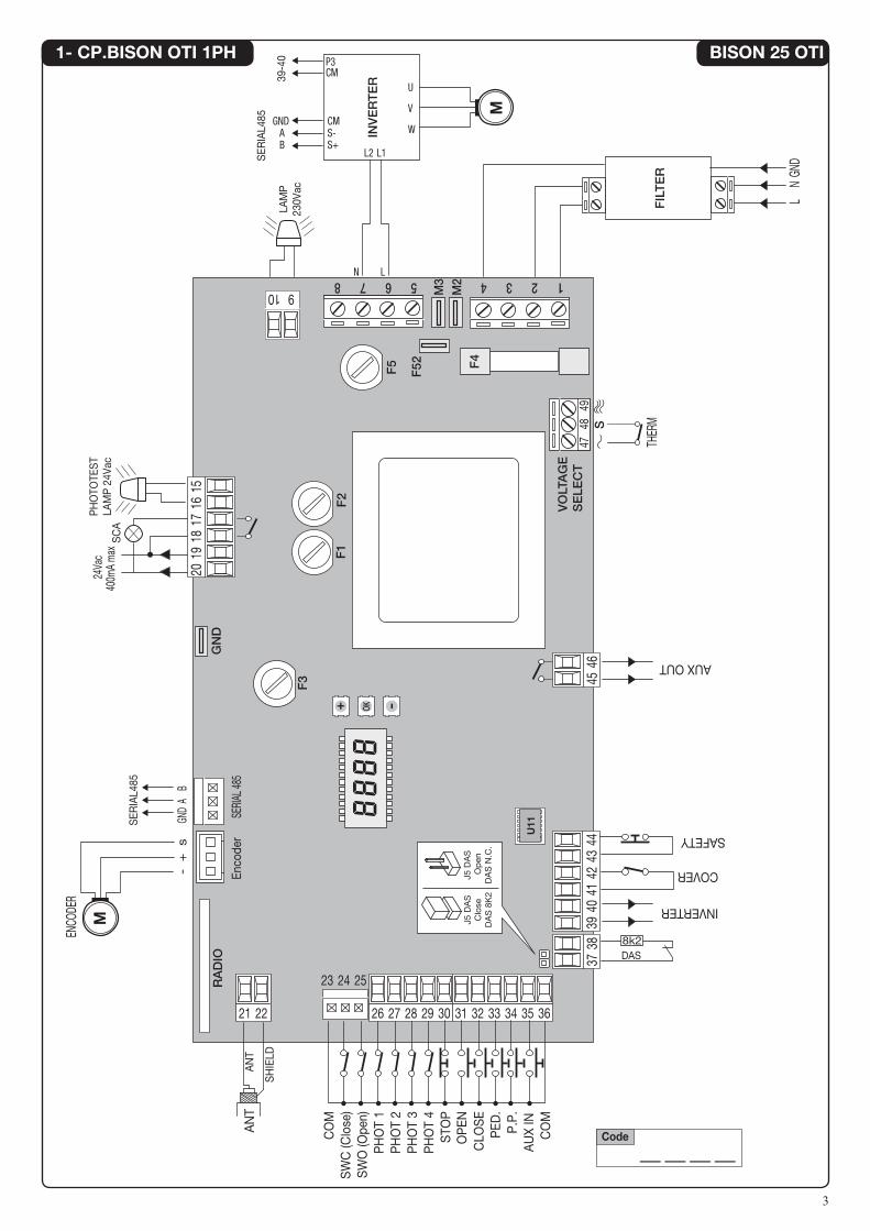
1- CP.BISON OTI 1PH
RADIO
GND
F52
M3
M2
F3
F1
F2
F5
363534333231
1516
1718
1920
10 912345678
4443
4241
4039
3029282726
252423
2221
3837
4645
Enco
der
SERI
AL 48
5
U11
SH
IELD
AN
TA
NT
VOLTAGE
SELE
CT
S
F4
8k2DAS
P.P
.
CO
M
PED
.
COVER
INVERTER
AUX OUT
CLO
SE
STO
PO
PEN
SW
C (C
lose
)S
WO
(Ope
n)P
HO
T 1
PH
OT
2P
HO
T 3
PH
OT
4
CO
M
LAM
P23
0Vac
PH
OTO
TES
TLA
MP
24V
acS
CA
FILTER
INVERTER
- +
s
GND
A B
M
ENCO
DER
M
J5 D
AS
Op
enD
AS
N.C
.
J5 D
AS
Clo
seD
AS
8K
2
24Va
c40
0mA
max
LN
GND
____Code
AU
X IN
SAFETY
SER
IAL4
85
SER
IAL4
85
39-4
0
4748
49
L1
U
P3
CMS-S+
GNDAB
CM
V
W
L2
N L
THER
M
BISON 25 OTI

4
2- CP.BISON OTI 3PH
RADIO
GND
F52
M3
M2
F3
F1
F2
F5
363534333231
1516
1718
1920
10 912345678
4443
4241
4039
30292827262221
3837
U11
VOLTAGE
SELE
CT
F4
8k2DAS
P.P
.A
UX
INC
OM
PED
.
OP
ENC
LOS
E
STO
P
SW
C (C
lose
)S
WO
(Ope
n)P
HO
T 1
PH
OT
2P
HO
T 3
PH
OT
4
CO
M
LAM
P23
0Vac
FILTER
INVERTER
- +
s
GND
A B
M
ENCO
DER
M
THER
M
24Va
c40
0mA
max
L1L2
L3GN
D
____Code
COVER
SAFETY
Enco
der
SERI
AL 48
5
252423
J2 D
AS
Op
enD
AS
N.C
.
J2 D
AS
Clo
seD
AS
8K
2
SH
IELD
AN
TA
NT
SER
IAL4
85
SER
IAL4
85
INVERTER
39-4
0
4645
AUX OUT
S47
4849
PH
OTO
TES
TLA
MP
24V
acS
CA
U
P3
CMS-S+
GNDAB
CM
V
W
T S R
BISON 30/45 OTI
5
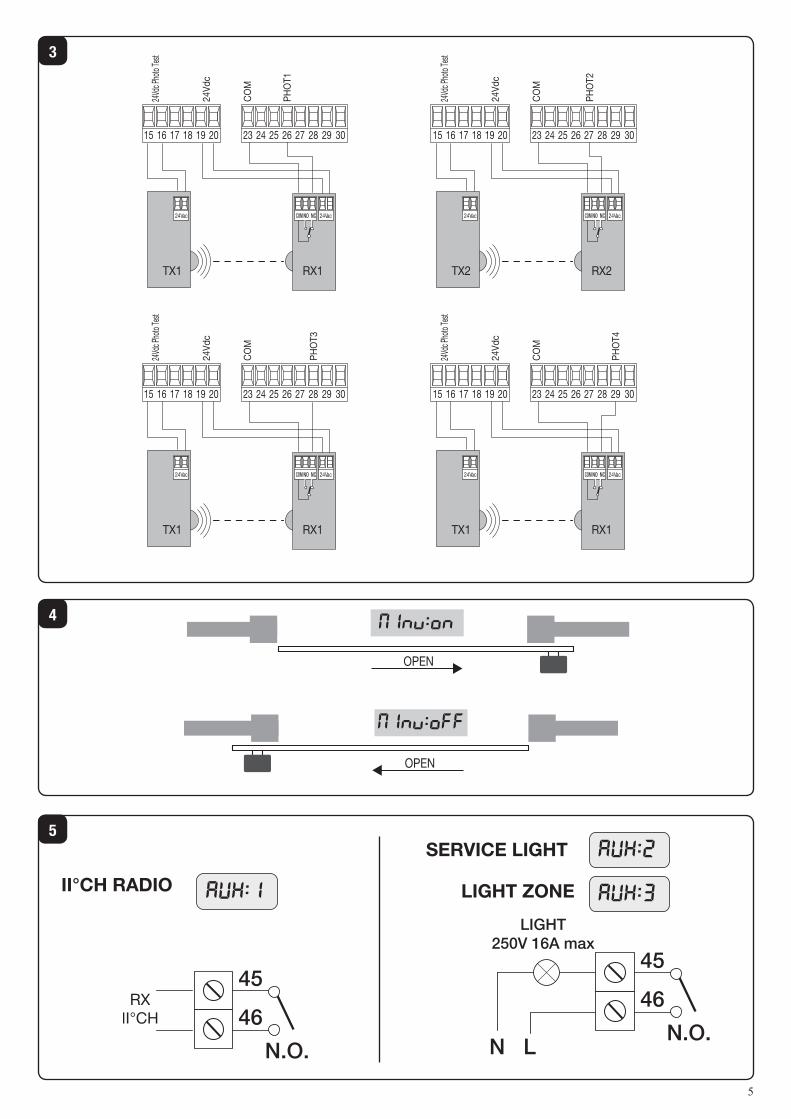
4
5
3
OPEN
OPEN
OPEN
OPEN
MINV:On
MINV:Off
201918171615 27 28 29 3026252423
24Vac 24VacCOM NCNO
RX1TX1
24Vd
c Pho
to Te
st
24Vd
c
CO
M
PHO
T1
201918171615 27 28 29 3026252423
24Vac 24VacCOM NCNO
RX2TX2
24Vd
c Pho
to Te
st
24Vd
c
CO
M
PHO
T2
201918171615 27 28 29 3026252423
24Vac 24VacCOM NCNO
RX1TX1
24Vd
c Pho
to Te
st
24Vd
c
CO
M
PHO
T3
201918171615 27 28 29 3026252423
24Vac 24VacCOM NCNO
RX1TX1
24Vd
c Pho
to Te
st
24Vd
c
CO
M
PHO
T4
LIGHT250V 16A max45
46
N.O.
AUX:2
AUX:3
AUX:1
45
N L
46
N.O.
LIGHT250V 16A max45
46
N.O.
AUX:2
AUX:3
AUX:1
45
N L
46
N.O.
II°CH RADIO
SERVICE LIGHT
LIGHT ZONE
15
WARNINGSThis manual has been especially written to be use by qualified fitters.
None of the information provide in this manual can be consi-dered as being of interest for the end users.
Preserve this manual for future needs.
The technician has to furnish all the information related to the step by step function, the manual and the emergency function of the operator, and to deliver the manual to the final user.
•Foresee on the supply net an onnipolar switch or selector with distance of the contacts equal or superior to 3 mms.
Verify that of the electrical system there is an awry differential interrupter and overcurrent protection.
Some typologies of installation require the connection of the shutter to be link at a conductive mass of the ground according to the regulations in force.
The electrical installation and the operating logic must comply with the regulations in force.
The leads fed with different voltages must be physically separate, or they must be suitably insulated with additional insulation of at least 1 mm.
The leads must be secured with an additional fixture near the terminals.
During installation, maintenance and repair, interrupt the power supply before opening the lid to access the electrical parts
Check all the connections again before switching on the power.
The unused N.C. inputs must be bridged.
The descriptions and the present illustrations in this manual are not binding. Leaving the essential characteristics of the product unchanged, the manufacturer reserves himself the right to bring any change of technical, constructive or com-mercial character without undertaking himself to update the present publication.
CE Declaration of ConformityDeclaration in accordance with Directives 2004/108/CE (EMC); 2006/95/CE (LVD)
The Manufacturer:AUTOMATISMI BENINCÀ SPAAddress:Via Capitello, 45 - 36066 Sandrigo (VI) - ItalyDeclares that the product:Control box for 1 motor, ideal for sliding doors:CP.BISON OTIconforms with the requirements of the following EU Directives:• DIRECTIVE 2004/108/CE OF THE EUROPEAN PARLIAMENT AND COUNCIL, 15 December 2004, in relation to the harmonisation of the legislation of member states regarding electromagnetic compatibility, in abrogation of Directive 89/336/CEE, per the following harmonised standards:EN 61000-6-2:2005, EN 61000-6-3:2007.• DIRECTIVE 2006/95/CE OF THE EUROPEAN PARLIAMENT AND COUNCIL, 12 December 2006, in relation to the harmonisation of the legislation of member states regarding electrical material intended to be used within certain voltage ranges, per the following harmonised standards:EN 60335-1:2002 + A1:2004 + A11:2004 + A12:2006 + A2:2006 + A13:2008; EN 60335-1-103:2003.
as applicable:• DIRECTIVE 1999/5/CE OF THE EUROPEAN PARLIAMENT AND COUNCIL, 9 March 1999 in relation to radio equip-ment and telecommunications terminals and the mutual recognition of their conformity, per the following harmonised standards:ETSI EN 301 489-3 V1.4.1 (2002) + ETSI EN 301 489-1 V1.4.1 (2002) + ETSI EN 300 220-3 V1.1.1(2000) + EN 60950-1 (2001)
Benincà Luigi, Legal representative.Sandrigo, 02/11/2010.
16
CP.BISON OTI CONTROL UNITINPUT/OUTPUT FUNCTIONS
CAUTION!: The CP.BISON OTI control unit is equipped with an embedded anti-crash device (amperometric sensor). Given the overall dimensions of the door leaves for which the device is intended, the latter cannot be considered a safety device. It is therefore STRICTRLY mANDATORY to install activated protection sen-sitive edges according to regulations in force.
N° Terminals Function Description
1-2-3-4 Power supply
Single-phase or three-phase mains power supply.The unit is powered through a mains filter applied before the control unit.Single-phase 1: Phase - 2: Neutral – 3: Not in use - 4: GNDThree-phase 1:L1 - 2:L2 - 3:L3 - 4:GND.
5-6-7-8 INVERTERSingle-phase or three-phase INVERTER connectionSingle-phase 6: Phase – 7: NEUTRALThree-phase 5:GND - 6:R - 7:S - 8:T.
9-10 Flashing light Connection of flashing light, 230VAC 40W max, or 115VAC 40W max, for BISON TI 115.
15-1624V Flashing light or Phototest
Connection to 24VAC flashing light or Phototest output for checked photocells.
17-18 SCA Normally open, voltage-fee contact for open gate indicator light, 24VAC 0.5A max
19-20 24 VAC Output, power supply of accessories, 24Vac/400mA max
SERIAL 485 Serial, inverter 485 serial communication between control logics and Inverter.
Encoder Encoder Connection to motor Encoder.
21-22 Antenna Connection to built-in radio receiver module of the antenna (21-signal/22-monitor).
23-36 COM Common, for all control inputs.
24 SWC Input, CLOSE limit switch (Normally Closed contact)
25 SWO Input, OPEN limit switch (Normally Closed contact)
26 PHOT 1 Input, Limit switch 1 (NC contact). It can be disconnected in the opening phase, see PH01 logics.
27 PHOT 2 Input, Limit switch 2 (NC contact). It can be disconnected in the opening phase, see PH02 logics.
28 PHOT 3 Input, Limit switch 3 (NC contact). It can be disconnected in the opening phase, see PH03 logics.
29 PHOT 4 Input, Limit switch 4(NC contact). It can be disconnected in the opening phase, see PH04 logics.
30 STOP Input, STOP push-button (Normally Closed contact)
31 OPEN Input, push-button for OPEN contact (Normally Open contact)
32 CLOSE Input, CLOSE push-button (Normally Open contact)
33 PED Input, push-button for pedestrian opening (Normally Open contact)
34 Step-by-Step Input, Step-by-Step push-button (Normally Open contact)
35 N/A Not in use
37-38 SAFETY
Input, sensitive safety edge.Safety edge of the resistive type: Jumper “DAS” closed.Safety edge of the mechanical type: Jumper “DAS” open.When the safety edge is activated, the door movement is stopped and reversed for around 3sec.
39-40 INVERTERSafety connection provides control of the hardware emergency stop to the inverter. It is always open with stopped motor, pressed SAFETY push-button or open motor removable side in BULL 40 OTL
TECHNICAL DATA
Mains power supplySingle-phase: (BISON 25 OTI) 230 VAC 50/60 Hz Three-phase: (BISON 30/45 OTI) 400 VAC 50/60 Hz
Output, Motor 1 motor, 230 V three-phase or 400 VAC three-phase
Motor max current BISON 25 OTI: 8A - BISON 40 OTI 2.6 A
Output, power supply of accessories 24VAC 0.4 A max.
Protection level IP54
Operating temperature -20°C / +50°C
Radio receiver433,92 MHz, incorporated and configurable (rolling-code or fixed+rolling-code+ ARC Advanced Rolling Code)
No. of codes storable in memory 64

17
41-42 COVERSafety switch, pre-wired to the micro-switch on the removable front side of the automatic system.It is activated when the cover is opened. Any operation is blocked.
43-44 SAFETYOptional safety switch. Connect the self-locking emergency push-button. Leave terminals short-circuited if not in use.
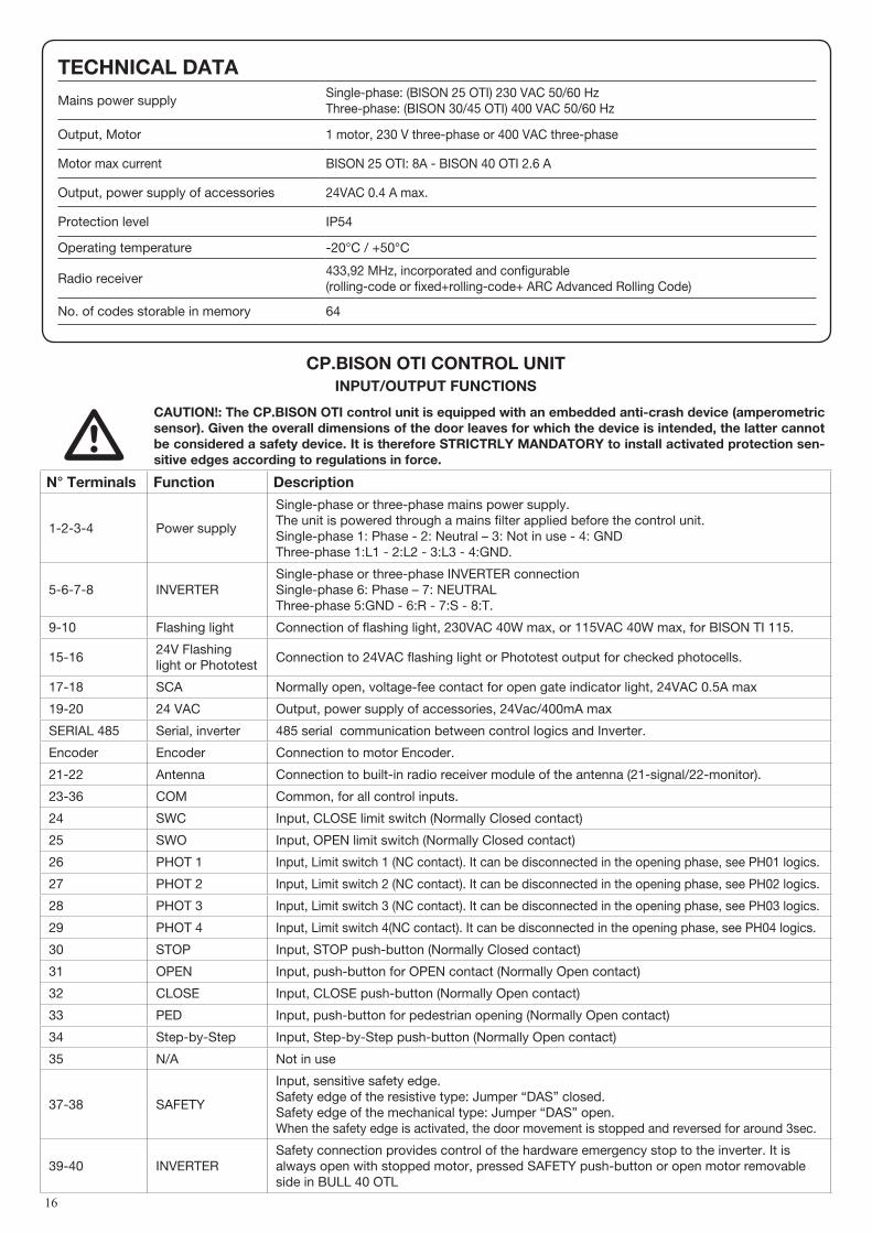
45-46 AUXAuxiliary output, configurable through the AUX parameter. Voltage-free contact, 250VAC 16A max.
47-48-49VOLTAGE SELECTOR
The power supply voltage is selected through a wire jack, or through a thermal switch, if available in the motor. 47 and 48 for single-phase power (230VAC).48 and 49 for three-phase power (400VAC).In the motors with thermal switch, its activation opens the contact and cuts off the power supply to the board. Follow connections shown If the board is removed or replaced.
Fuse Type Description
F1 250V T1A Protection, power supply of accessories
F2 250V T400mA Protection, logics of board
F3 250V T630mA Protection, common inputs and serial of inverter
F4 500V T125mA Protection, transformer primary
F5 250V T500mA Protection, lashing light, 230V
HOW TO CHECK CONNECTIONS1) Cut off power supply.2) Manually release the door/gate and push it for about half stoke. Lock the door again.3) Restore power supply.4) Send a step-by-step command through push-button <-> on the control unit (LCD display off). To stop the door/gate press <-> once
more. 5) The door/gate should open. If not, use the MINV logics to change the opening direction.
INVERTERThe CP.BISON OTI control unit is provided with serial connections for the control of a pre-installed inverter on the gear motors of the BISON series. The inverter allows to enhance the functional performance of the motor as regards control of the torque, speed and safety.Although the pre-installed inverter is provided with programming functions, none of them must be changed by the installer because the CP.BISON control unit directly controls all the operating parameters. If the device is to be replaced, ask an original spare part to the manufacturer and carry out its wiring in compliance with connections shown in the handbook supplied with the spare part itself. Do not use inverters which are not supplied by the manufacturer for any reason whatsoever.
PROGRAmmINGThe programming of the various functions of the control unit is carried out using the LCD display on the control unit and setting the desired values in the programming menus described below.The parameters menu allows you to assign a numerical value to a function, in the same way as a regulating trimmer.The logic menu allows you to activate or deactivate a function, in the same way as setting a dip-switch.Other special functions follow the parameters and logic menus and may vary depending on the type of control unit or the software release.
TO ACCESS PROGRAmmING1 – Press the button <PG>, the display goes to the first menu, Parameters “PAR”. 2 – With the <+> or <-> button, select the menu you want.3 – Press the button <PG>, the display shows the first function available on the menu.4 – With the <+> or <-> button, select the function you want.5 – Press the button <PG>, the display shows the value currently set for the function selected.6 – With the <+> or <-> button, select the value you intend to assign to the function.7 – Press the button <PG>, the display shows the signal “PRG” which indicates that programming has been completed.
NOTESPressing <-> with the display turned off means an impulse of P.P. Simultaneously pressing <+> and <-> from inside a function menu allows you to return to the previous menu without making any changes. Hold down the <+> key or the <-> key to accelerate the increase/decrease of the values.After waiting 30s the control unit quits programming mode and switches off the display.
18
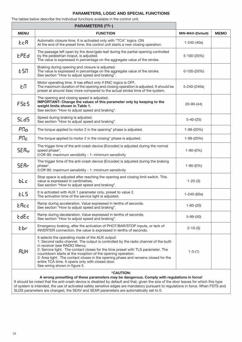
PARAmETERS, LOGIC AND SPECIAL FUNCTIONS The tables below describe the individual functions available in the control unit.
PARAmETERS (PAR)
mENU FUNCTION mIN-mAX-(Default) mEmO
TCAAutomatic closure time. It is activated only with “TCA” logics :ONAt the end of the preset time, the control unit starts a new closing operation. 1-240-(40s)
TpedThe passage left open by the door/gate leaf during the partial opening controlled by the pedestrian inoput, is adjusted. The value is expressed in percentage on the aggregate value of the stroke.
5-100-(20%)
tsmBraking during opening and closure is adjusted. The value is expressed in percentage on the aggregate value of the stroke.See section “How to adjust speed and braking”.
0-100-(20%)
TMMotor operating time. It has effect only if ENC logics is OFF.The maximum duration of the opening and closing operation is adjusted. It should be preset at around 4sec more compared to the actual stroke time of the system.
5-240-(240s)
FSTS
The opening and closing speed is adjusted.ImPORTANT: Change the values of this parameter only by keeping to the weight limits shown in Table 1.See section “How to adjust speed and braking”.
20-90-(44)
sldSSpeed during braking is adjusted.See section “How to adjust speed and braking”. 5-40-(25)
PMO The torque applied to motor 2 in the opening* phase is adjusted. 1-99-(20%)
PMC The torque applied to motor 2 in the closing* phase is adjusted. 1-99-(20%)
sEavThe trigger time of the anti-crash device (Encoder) is adjusted during the normal speed phase*. 0:Off-90: maximum sensibility - 1: minimum sensitivity
1-90-(0%)
sEarThe trigger time of the anti-crash device (Encoder) is adjusted during the braking phase*.0:Off-90: maximum sensibility - 1: minimum sensitivity
1-90-(0%)
blcStop space is adjusted after reaching the opening and closing limit switch. This value is expressed in centimetres. See section “How to adjust speed and braking”.
1-20-(3)
TLSIt is activated with AUX 1 parameter only, preset to value 2. The activation time of the service light is adjusted. 1-240-(60s)
TACCRamp during acceleration. Value expressed in tenths of seconds.See section “How to adjust speed and braking”. 1-60-(20)
TDECRamp during deceleration. Value expressed in tenths of seconds.See section “How to adjust speed and braking”. 5-99-(50)
TbrEmergency braking, after the activation of PHOT/BAR/STOP inputs, or lack of INVERTER connection, the value is expressed in tenths of seconds.
2-10-(3)
AUX
It selects the operating mode of the AUX output:1: Second radio channel. The output is controlled by the radio channel of the built-in receiver (see RADIO Menu).2: Service light. The contact closes for the time preset with TLS parameter. The countdown starts at the inception of the opening operation.3: Area light. The contact closes in the opening phase and remains closed for the entire TCA time. It opens only with closed door. See wiring shown in figure 5.
1-3-(1)
*CAUTION: A wrong presetting of these parameters may be dangerous. Comply with regulations in force!
It should be noted that the anti-crash device is disabled by default and that, given the size of the door leaves for which this type of system is intended, the use of activated safety sensitive edges are mandatory pursuant to regulations in force. When FSTS and SLDS parameters are changed, the SEAV and SEAR parameters are automatically set to 0.

19
LOGIC (LOG)
mENU FUNCTION ON-OFF-(Default) mEmO
TCAEnables or disables automatic closingOn: automatic closing enabledOff: automatic closing disabled
(OFF)
IBL
Enables or disables multi-flat function.On: multi-flat function enabled. The step-by-step and perdestrian commands have no effect during the opening phase.Off: multi-flat function disabled.
(OFF)
IBCADuring the TCA phase, the PP controls are enabled or disabled.On: PP controls are disabled.Off: PP controls are enabled.
(OFF)
SCL
The rapid closure is enabled or disabled. It can be activated only if TCA:ONOn: enabled rapid closure. With open gate, the photocell activation causes the automatic closure after 3 s. If the photocell is activated during the opening phase, the operation is completed and closure starts after 3s Off: disabled rapid closure.
(OFF)
PPThe operating mode of “P.P. Push button” and of the transmitter are selected.On: Operation : OPEN > CLOSE > OPEN >Off: Operation: OPEN > STOP > CLOSE > STOP >
(OFF)
PRE
Forewarning flashing light enabled or disabled.On: enabled forewarning flashing light. The flashing light is activated 3 s before the starting of the motor.Off: disabled forewarning flashing light.
(OFF)
HTR
The Service Man function is enabled or disabled.On: Service Man operation. The OPEN/CLOSE push buttons should be kept pressed for the entire operating time.Off: Automatic operation.
(OFF)
LTCADuring the TCA time, the blinker is enabled or disabled.On: Enables blinker.Off: Disables blinker.
(OFF)
ENC
The Encoder is enabled or disabled.On: Activated Encoder.Off: Not activated Encoder. The encoder only detects the door/gate stroke. In the event of maintenance operations, it is advisable to deactivate it only temporarily.
(ON)
Pho1The PHOT 1 input is enabled or disabled in the opening phase.On: Photocell 1 activated only in the closing phase.Off: Photocell 1 activated in both opening and closing phases.
(OFF)
Pho2 As per PH01, but referred to PHOT 2 input. (OFF)
Pho3 As per PH01, but referred to PHOT 3 input. (OFF)
Pho4 As per PH01, but referred to PHOT 4 input. (OFF)
tst1
The check on the photocell connected to PHOT1 input is activated or deactivatedBefore operation, the control unit checks the switching of the photocell contact. If the checks are not successful, the door/gate will not move.On: activated check on photocell.Off: deactivated check on photocell.
(OFF)
tst2 As for TST1, but referred to PHOT2 input (OFF)
tst3 As for TST1, but referred to PHOT3 input (OFF)
tst4 As for TST1, but referred to PHOT$ input (OFF)
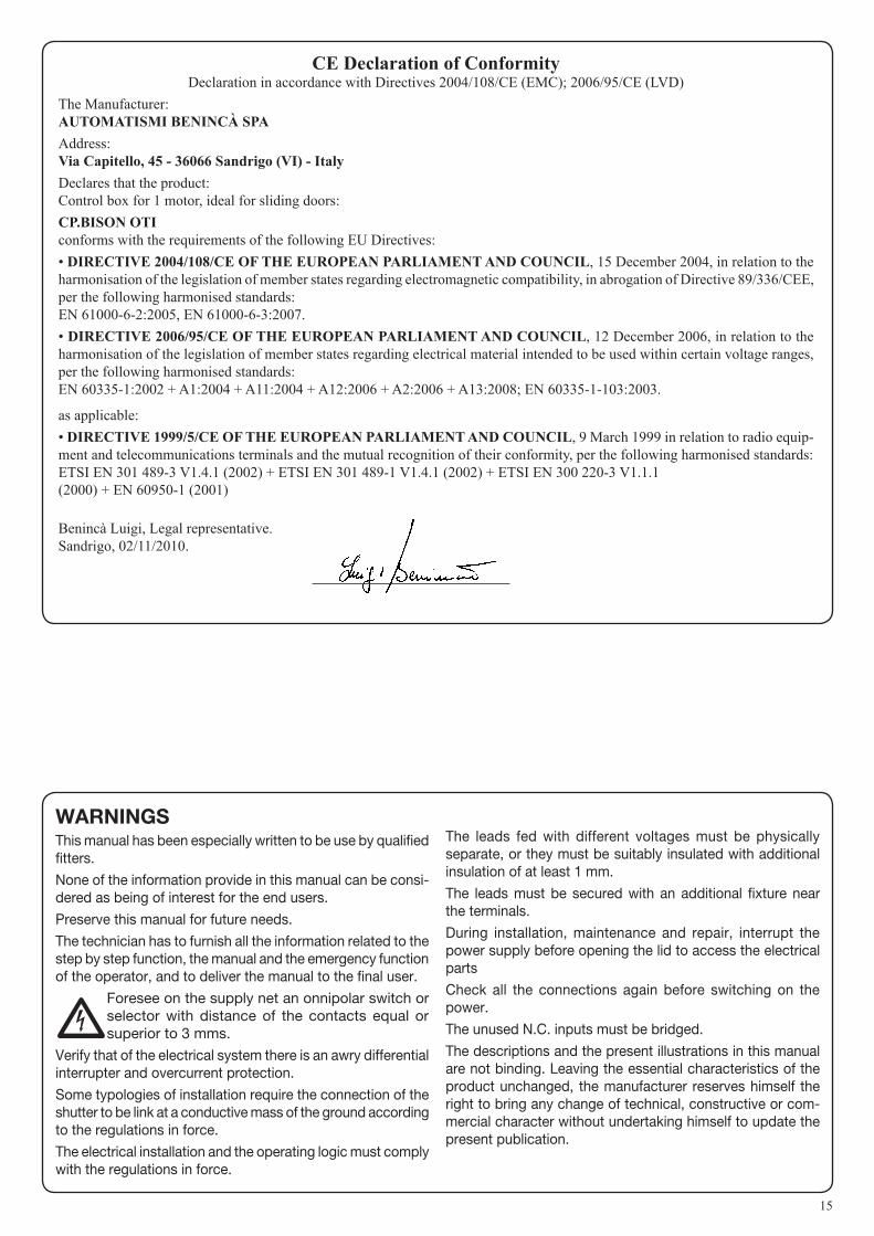
MINVThe opening direction of the motor is selected (see Fig. 4):On: Right side motor mount Off: Left side motor mount
(OFF)
20
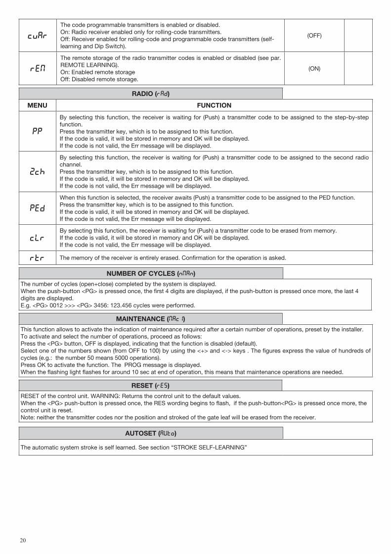
CVAR
The code programmable transmitters is enabled or disabled.On: Radio receiver enabled only for rolling-code transmitters.Off: Receiver enabled for rolling-code and programmable code transmitters (self-learning and Dip Switch).
(OFF)
REM
The remote storage of the radio transmitter codes is enabled or disabled (see par. REMOTE LEARNING).On: Enabled remote storage Off: Disabled remote storage.
(ON)
RADIO (RAD)
mENU FUNCTION
PP
By selecting this function, the receiver is waiting for (Push) a transmitter code to be assigned to the step-by-step function.Press the transmitter key, which is to be assigned to this function.If the code is valid, it will be stored in memory and OK will be displayed.If the code is not valid, the Err message will be displayed.
2Ch
By selecting this function, the receiver is waiting for (Push) a transmitter code to be assigned to the second radio channel.Press the transmitter key, which is to be assigned to this function.If the code is valid, it will be stored in memory and OK will be displayed.If the code is not valid, the Err message will be displayed.
PED
When this function is selected, the receiver awaits (Push) a transmitter code to be assigned to the PED function.Press the transmitter key, which is to be assigned to this function.If the code is valid, it will be stored in memory and OK will be displayed.If the code is not valid, the Err message will be displayed.
CLRBy selecting this function, the receiver is waiting for (Push) a transmitter code to be erased from memory.If the code is valid, it will be stored in memory and OK will be displayed.If the code is not valid, the Err message will be displayed.
RTR The memory of the receiver is entirely erased. Confirmation for the operation is asked.
NUmBER OF CYCLES (Nman)
The number of cycles (open+close) completed by the system is displayed.When the push-button <PG> is pressed once, the first 4 digits are displayed, if the push-button is pressed once more, the last 4 digits are displayed.E.g. <PG> 0012 >>> <PG> 3456: 123.456 cycles were performed.
mAINTENANCE (maci)
This function allows to activate the indication of maintenance required after a certain number of operations, preset by the installer.To activate and select the number of operations, proceed as follows:Press the <PG> button, OFF is displayed, indicating that the function is disabled (default). Select one of the numbers shown (from OFF to 100) by using the <+> and <-> keys . The figures express the value of hundreds of cycles (e.g.: the number 50 means 5000 operations).Press OK to activate the function. The PROG message is displayed.When the flashing light flashes for around 10 sec at end of operation, this means that maintenance operations are needed.
RESET (RES)
RESET of the control unit. WARNING: Returns the control unit to the default values.When the <PG> push-button is pressed once, the RES wording begins to flash, if the push-button<PG> is pressed once more, the control unit is reset.Note: neither the transmitter codes nor the position and stroked of the gate leaf will be erased from the receiver.
AUTOSET (AUTO)
The automatic system stroke is self learned. See section “STROKE SELF-LEARNING”
21
PASSWORD (CODE)
It allows to type in an access protection code to the programming of the control unit.A four-character alphanumeric code can be typed in by using the numbers from 0 to 9 and the letters A-B-C-D-E-F.The default value is 0000 (four zeros) and shows the absence of a protection code.While typing in the code, this operation can be cancelled at any moment by pressing keys + and – simultaneously. Once the password is typed in, it is possible to act on the control unit by entering and exiting the programming mode for around 10 minutes in order to allow adjustments and tests on functions.By replacing the 0000 code with any other code, the protection of the control unit is enabled, thus preventing the access to any other menu. If a protection code is to be typed in, proceed as follows:- select the Code menu and press OK.- the code 0000 is shown, also in the case a protection code has been previously typed in.- the value of the flashing character can be changed with keys + and -.- press OK to confirm the flashing character, then confirm the following one. - after typing in the 4 characters, a confirmation message “CONF” appears.- after a few seconds, the code 0000 appears again- the previously stored protection code must be reconfirmed in order to avoid any accidental typing in.If the code corresponds to the previous one, a confirmation message “OK” appears.The control unit automatically exits the programming phase. To gain access to the Menus again, the stored protection code must be typed in.ImPORTANT: TAKE NOTE of the protection code and KEEP IT IN A SAFE PLACE for future maintenance operations. To remove the code from a protected control unit, enter the programming mode with the password and reset the code to the 0000 default value.IF YOU LOOSE THE CODE, PLEASE CONTACT THE AUTHORISED SERVICE CENTER FOR THE TOTAL RESET OF THE CONTROL UNIT.
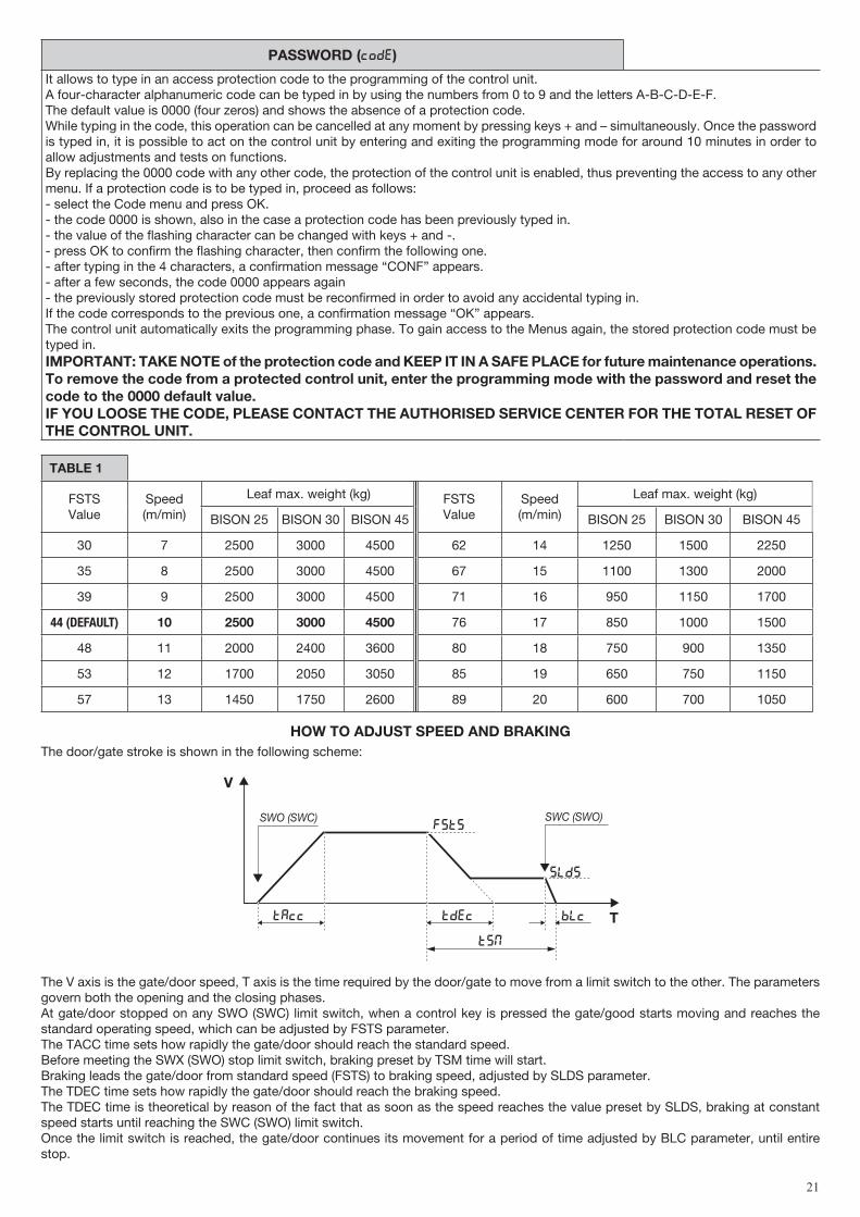
TABLE 1
FSTSValue
Speed (m/min)
Leaf max. weight (kg) FSTSValue
Speed (m/min)
Leaf max. weight (kg)
BISON 25 BISON 30 BISON 45 BISON 25 BISON 30 BISON 45
30 7 2500 3000 4500 62 14 1250 1500 2250
35 8 2500 3000 4500 67 15 1100 1300 2000
39 9 2500 3000 4500 71 16 950 1150 1700
44 (DEFAULT) 10 2500 3000 4500 76 17 850 1000 1500
48 11 2000 2400 3600 80 18 750 900 1350
53 12 1700 2050 3050 85 19 650 750 1150
57 13 1450 1750 2600 89 20 600 700 1050
HOW TO ADJUST SPEED AND BRAKINGThe door/gate stroke is shown in the following scheme:
V
T
FSTS
slds
BLCTAcc Tdec
TSM
SWO (SWC) SWC (SWO)
The V axis is the gate/door speed, T axis is the time required by the door/gate to move from a limit switch to the other. The parameters govern both the opening and the closing phases.At gate/door stopped on any SWO (SWC) limit switch, when a control key is pressed the gate/good starts moving and reaches the standard operating speed, which can be adjusted by FSTS parameter. The TACC time sets how rapidly the gate/door should reach the standard speed.Before meeting the SWX (SWO) stop limit switch, braking preset by TSM time will start.Braking leads the gate/door from standard speed (FSTS) to braking speed, adjusted by SLDS parameter.The TDEC time sets how rapidly the gate/door should reach the braking speed.The TDEC time is theoretical by reason of the fact that as soon as the speed reaches the value preset by SLDS, braking at constant speed starts until reaching the SWC (SWO) limit switch.Once the limit switch is reached, the gate/door continues its movement for a period of time adjusted by BLC parameter, until entire stop.

22
IMPORTANT:- For the correct operation of parameters it is mandatory that the stroke learning be carried out correctly (see STROKE LEARNING).- If the FSTS speed is increased, TSM, TACC and TDEC values must be increased proportionally in order to avert any mechanical
stress to the gear motor. A TSM value, which is too short, combined with a TDEC value, which is too high, might result in the cancellation of the SLDS braking
phase due to the gate leaf friction and the triggering of the limit switches when the speed is still high. This situation must be absolutely avoided.
- It should be noted that the FSTS value can be changed only in compliance with the limits shown in Table 1.- The AUTO function does not change the default values of the above-mentioned parameters. The latter must be preset by the installer
according to the gate/door specifications.
STROKE LEARNING (LOGIC ENC:ON)For a correct operation of braking it is essential that the stroke is memorised. This can be performed either using the above described AUTO function or when the first operation is completed (then carried out without interruptions) from open limit switch to close limit switch (or viceversa).However, these values can be manually modified at a second time.If the encoder is activated, the position of the gate leaf is stored in memory and reset also in case of power failure.If the encoder is disabled, in case of power failure a new complete operation will be required to memorise the stroke and reset brak-ing. Note: If the automatic system is released and manually operated, the following operation might not perform braking correctly. Also in this case a new complete operation will be required to reset the regular operation of the system.
If the encoder is disabled, the stroke self-learning cannot be carried out. If the stroke self-learning is carried out with disabled encoder, the ERR message is shown.To disable the Encoder, it is MANDATORY to adjust the TM parameter by subtracting the TSM braking time (normal speed time= TM-TSM).
TRANSmITTER REmOTE LEARNINGIf the transmitter code is already stored in the receiver, the remote radio learning can be carried out (without accessing the control unit). The REM logics must be ON.IMPORTANT: The procedure should be carried out with gate in the opening phase, during the TCA dwell time.Proceed as follows:1 Press the hidden key of the transmitter, the code of which has already been stored in memory.2 Within 5 seconds, press the already memorised transmitter key corresponding to the channel to be matched to the new transmitter. The flashing light switches on.3 Within 10 seconds, press the hidden key of the new transmitter.4 Within 5 seconds, press the key of the new transmitter to be matched to the channel selected at item 2. The flashing light switches off.5 The receiver stores the new transmitter code and exits from the programming mode immediately.
ERROR mESAGESSome messages that are displayed in the event of malfunctions are shown hereunder:
err Error, self-calibration If the error occurs during self-learning, check the PP/STOP/PHC/PHO/PED/BAR inputs or whether frictions occur during the door leaf stoke.
Err1 Error, Inverter/Cover/Safety
It occurs in the following cases:- the SAFETY contact is open.- the COVER contact is open.- The inverter is faulty. Contact the technical assistance centre.
Err2 Error, photocells (Autotest) Check that photocells are correctly operating.
Err3 Error, encoder Check connections to the encoder.
Err4 Error, sensitive edge Check connections to sensitive edge
Err5 Error, phototest Check that photocells connections (Fig.3)
Ecom Error, inverter communication Check connections to 485 serial between control unit and inverter
amp Triggering of the amperometric sensorAn obstacle or a point of friction has caused the triggering of the am-perometric sensor. Remove the obstacle or check the door stroke.
F 00
F 15Inverter, error/alarm Take note of the error number and contact the technical assistance
LCD DISPLAYThe LCD display can be turned by 180°.- Cut off mains power supply- Press PGM- While keeping PGM pressed, reset the mains power supply- Keep PGM pressed (around 5 sec) until the software version appears, turned by 180°. Normally proceed with programming.

23
DIAGNOSTICSIn the event of malfunctions, by pressing key + or - the status of all inputs (limit switches, control and safety) can be displayed. One segment of the display is linked to each input. In the event of failure it switches on according to the following scheme.
PHO1
SWC
STOP
SWO
PHO2 DAS
PHO4PHO3
P.P. PED OPEN CLOSE
WASTE DISPOSALIf the product must be dismantled, it must be disposed according to regulations in force regarding the differentiated waste disposal and the recycling of components (metals, plastics, electric cables, etc..). For this operation it is advisable to call your installer or a specialised company.