court and municipal room remodel construction documents systems... · court and municipal room...
TRANSCRIPT

Court and Municipal Room Remodel Construction Documents City of Eaton Eaton, CO
AUDIO VIDEO SYSTEMS AND EQUIPMENT 27 4116 - 1
SECTION 27 4116 – AUDIO VIDEO SYSTEMS AND EQUIPMENT
PART 1 - GENERAL
1.1 CONTRACT DOCUMENTS
A. The General and Special Conditions are hereby made a part of this Section. Where requirements of this Section are at odds with requirements stated in any Special or Supplementary Conditions, the more stringent requirements shall apply.
B. The Contract Documents are complementary and are intended to include or imply all items required for the proper execution and completion of the work. Any item or work required by the Specification or other portion of the Contract Documents, but not shown on the drawings, or shown on the drawings but not described in the Specification, shall be provided and installed by the Contractor as if shown or mentioned in both.
C. The Consultant may furnish additional instruction or clarification necessary for the proper execution of the work. Instructions or clarifications shall be consistent with the Contract Documents, or agreed upon modifications thereof, and inferable therefrom. In giving instruction or clarification, only the Contracting Officer shall have the authority to make minor changes in the work that will not entail an increase in the Contract price or time.
D. Copies of drawings and specifications regardless of how furnished are the property of the Owner, and are not to be used on any other work or project. No contract documents may be released for publication or to any other party without the written consent of the Owner and Consultant. All references to “the Owner” in this document refer to the City of Eaton.
1.2 GOVERNING CLAUSE
A. For the sake of brevity these specifications omit phrases such as "Contractor shall furnish and install," "unless otherwise noted or specified," etc.; nevertheless, the requirements of the specifications are mandatory, and these phrases shall be inferred. The mention of materials and operations implies the Contractor shall furnish and install such materials and perform such operations to the overall standards set by the Contract Documents. Exceptions are noted herein or shown on the drawings.
B. In the event that a Consultant is not a participant in this project after award of contract, all references to “Consultant” in this document shall be replaced with “Owner”.
1.3 SCOPE OF WORK
A. Work under this Contract includes all labor, materials, tools and equipment, transportation services, supervision, coordination, etc., necessary to complete the installation of high quality A/V Systems and Control Systems, in excellent working order, as described in these specifications and the associated drawings and in accordance with good engineering practice, and to maintain the systems throughout the Warranty period. The systems shall be called the "A/V Systems" and the Contractor the "A/V System Contractor". The systems include, but are not limited to, the following major items: 1. Audio mixers, equalizers, amplifiers, program sources, digital recording devices,
microphones and other signal processing equipment; 2. Loudspeakers and loudspeaker mounting, aiming, rigging, and support hardware;
Court and Municipal Room Remodel Construction Documents City of Eaton Eaton, CO
AUDIO VIDEO SYSTEMS AND EQUIPMENT 27 4116 - 2
3. Video switching, video over IP transmitters/receivers, video display equipment, video conferencing systems, cameras, and other video playback devices.
4. Network equipment; 5. Control equipment; 6. Equipment racks, cabinetry, and furniture; 7. System accessories; 8. Cable, connectors, adapters, plates, panels, transformers, and other interface devices.
B. The Contract also includes: 1. Verification of dimensions and conditions at the job site. 2. Preparation of submittal information. 3. Installation in accordance with the contract documents, manufacturer's
recommendations, and all applicable code and legal requirements. 4. Initial tests and adjustments, written report, demonstration for approval, final adjustments,
and documentation. 5. Instruction of operating personnel; provision of manuals. 6. Maintenance services; Warranty.
1.4 RELATED WORK
A. Section 27 4160 – Audio DSP Configuration
B. Section 27 4170 – Audio Video Control System Programming
1.5 PRODUCTS INSTALLED BUT NOT SUPPLIED UNDER THIS SECTION
A. Certain equipment may be identified after the bid is awarded as Owner Furnished Equipment (OFE). Owner Furnished Equipment is presently part of the Owner's system, or will be provided by the Owner, and will be delivered to Contractor's off-site construction facility, delivered to the Contractor's on-site secured storage area, or installed on site by others, as appropriate, for incorporation into the system.
B. Inspect the OFE, and notify the Owner promptly in writing of damage or defect and the extent of repair and/or adjustment required to bring the OFE to original specification. Service OFE only as directed by the Owner, under the arrangements of a separate contract.
C. Incorporate into the system as if provided new, excepting Warranty coverage.
1.6 RESPONSIBILITY AND RELATED WORK
A. Coordinate work with Owner personnel involved in this project, Consultant, representatives and employees/subcontractors employed of/by Owner, including electricians and the scheduled work of other trades.
B. Conduit; wireways; floor, wall, pull, and junction boxes; metal loudspeaker enclosures; and AC power circuits and ground wiring to the A/V System junction box(es), permanently installed in the building or in architectural millwork shall be provided by the General/Electrical Contractor unless otherwise noted. This does not relieve the A/V System Contractor from responsibility for a complete working system, and coordination with the electricians and representatives of the Owner in the course of his or her installation is required to achieve a correct conduit system. Failures in coordination shall not be reason for additional payment to correct omissions or errors in conduit or box installation.

Court and Municipal Room Remodel Construction Documents City of Eaton Eaton, CO
AUDIO VIDEO SYSTEMS AND EQUIPMENT 27 4116 - 3
C. Distribute AC Power within the A/V System from the junction box(es). All cable for this distribution, and conduit, wireways, receptacles, and boxes in equipment racks or furniture provided by the A/V System Contractor, are the responsibility of the A/V System Contractor.
D. Provide and install all A/V System cable and wiring. Unless otherwise noted, install all wiring in conduit, enclosed wireways, or cable trays.
E. Notwithstanding any detailed information in the Contract Documents, it is the responsibility of the A/V System Contractor to supply systems in full working order, and of the Owner and A/V System Contractor to meet all code requirements for the installation of conduit and cable, respectively.
F. Notify the Consultant of any discrepancies in part numbers, sizes, or quantities before bid. Failing to provide such notification, supply items, sizes, and quantities according to the intent of the design as described in the Specifications and Drawings, without claim for additional payment.
G. Supply accessories and minor equipment items needed for a complete and properly functioning system, or where required to meet the specified performance, even if not specifically mentioned herein or on the drawings, without claim for additional payment.
H. Cooperate with all trades present on the project, so lost time, work stoppages, interference, and work inefficiencies do not occur. Assure labor "harmony" among personnel and subcontractors, and with other trades associated with construction, delivery, installation, and testing of the facility. Coordinate and schedule all on-site activities with the Owner. A/V System Contractor shall work and complete all on-site tasks in accordance with the access to the site provided by the Owner.
1.7 REFERENCES AND ADDITIONAL APPLICABLE DOCUMENTS
A. The workmanship and installation of the audio video systems and equipment shall adhere to industry best practices and all national and local codes.
B. The following documents, or the versions closest in time prior to the release of this specification, shall form a part of this specification to the extent specified herein. Where the requirements of these documents conflict with the instructions herein, the requirements of this specification shall govern. 1. National Fire Protection Association (N.F.P.A.) National Electrical Code (NEC). 2. Electronics Industry Association/Telecommunications Industry Association (EIA)/TIA)
Standards. 3. International Telecommunications Union (ITU) Standards. 4. Society of Motion Picture and Television Engineers (SMPTE) Standards. 5. Audio Engineering Society (AES) Standards. 6. American National Standards Institute (ANSI) 7. Building Seismic Safety Council (B.S.S.C.)
C. Other References: 1. Shields and Grounds: Safety, Power Mains, Studio, Cable and Equipment, (special
excerpt) The June 1995 issue of the Journal of the Audio Engineering Society. 2. Grounding and Shielding Techniques in Instrumentation, by Ralph Morrison, published by
John Wiley and Sons, Inc.; 3rd edition (March, 1986) ISBN: 0471838055 3. Sound Reinforcement Handbook, by Gary Davis and Ralph Jones, published by Hal
Leonard Publishing Corporation; 2nd edition (March 1, 1990) ISBN: 0881889008 4. DOJ 28 CFR Part 36, Appendix A to Part 36 - Standards for Accessible Design:
Americans with Disabilities Act Accessibility Guidelines (ADAAG). 5. A Clean Audio Installation Guide, Allen H Burdick, Benchmark Media Systems, Inc., (800)
262-4675, (available on the World Wide Web at http://www.benchmarkmedia.com/);
Court and Municipal Room Remodel Construction Documents City of Eaton Eaton, CO
AUDIO VIDEO SYSTEMS AND EQUIPMENT 27 4116 - 4
6. Audio System Design and Installation, Phillip Giddings, Butterworth-Heinemann; Reissue edition (July, 1990) ISBN: 0672226723
7. Sound System Engineering (2nd Edition), Don & Carolyn Davis, Focal Press; 2 edition (May 19, 1997) ISBN: 0240803051
1.8 DEFINITIONS
A. Owner: City of Eaton, CO
B. Architect: Thorp Associates
C. Consultant: K2 | Consultants in Acoustics, AV, and Technology
D. Contractor: The “Contractor” referred to in this specification is the A/V Systems Contractor selected by the Owner, through competitive bidding or negotiation, to provide the A/V systems described by this specification, and to whom a contract has been awarded to do so.
E. Masculine Pronoun: In all cases where a masculine pronoun is used within these specifications, the pronoun is used in the interest of simplicity of syntax, and the reference shall be interpreted as genderless.
1.9 SYSTEM DESCRIPTION OVERVIEW
A. General Description 1. Audio Systems
a. A new fully functional audio system shall be provided for the Court and Municipal Room. This system would allow for both the amplification of voice as well as audio from video sources. The system shall be designed as a true mix-minus system that permits clear audio to be heard in all locations but without feedback commonly associated with standard sound reinforcement systems.
b. A Shure/DIS full-featured turnkey conferencing system with integrated microphone, loudspeaker, request-to-speak and voting capabilities shall be provided. The conference systems shall also be capable of being moved and reconfigured in the dais well/staff area. The system components shall simply be set on the desks and shall plugged in based on the requirements of the meeting or proceedings. This shall allow for several flexible configurations and the repositioning of staff between the two tables as needed. This approach shall also permit either floor box to be used for the Clerk’s control station as well (making the control station variable).
c. The conference system shall include seven (7) units at the permanent dais, five (5) at the portable staff table(s) locations, one (1) at the portable lectern, and one (1) wireless hand held microphone system for audience questions and for ad hoc presentations (awards, recognitions, presentations to council, etc.).
d. The system shall include all required audio digital signal processing (DSP) for mixing and control, a multi-channel audio amplifier, six (6) pendant mounted ceiling loudspeakers over the audience area, and two (2) loudspeakers (on individual volume control) for the Lobby/Waiting Area.
e. The system shall include two (2) “chairman” stations located the mayor/judge and clerk locations respectfully. In addition to the features outlined above, the chairman stations shall include a 3.5” touch screen that shall allow for simple management of the request-to-speak queue, microphone muting, voting, ad hoc voting control, and for the display of voting results. It is the intent that the Mayor, Judge, and Clerk(s) have straightforward control over basic audio and voting elements using this screen. The system shall be capable of tailoring and configuring the screen based on City of Eaton requirements as well—if more or less features are desired at either location.

Court and Municipal Room Remodel Construction Documents City of Eaton Eaton, CO
AUDIO VIDEO SYSTEMS AND EQUIPMENT 27 4116 - 5
f. At each of the six (6) dais locations there shall be “delegate” stations that shall include the basic system features outlined above (microphone, loudspeaker, and controls). However, instead of a touch screen, the delegate station shall have five function buttons for voting and control.
g. At each of the staff locations at the tables as well as the lectern there shall be a “speaker” station that shall just include the basic system features outlined above (microphone, loudspeaker, and volume controls). No additional control or voting features shall be provided at these locations. It is the intent that the speaker station at the lectern be recessed into the top of the lectern work surface so as to be permanently affixed.
h. The audio system shall also include a network based audio recording device that shall allow for the audio recording of council meetings and judicial proceedings. All recordings shall be made locally on solid state media and then uploaded to a City of Eaton network file folder for transcription, distribution, and archiving purposes. The installation of this device shall require coordination with City of Eaton IT staff for both a network drop at the AV rack as well as a file path to the City of Eaton server for storage and archiving.
i. The audio system, as well as other rooms systems and recording, shall be controlled using a 15” touch monitor. The touch monitor shall be utilized by the Clerk(s) and shall utilize an intuitive graphical user interface with imbedded video window. This shall allow the 15” touch monitor to be used for both system control as well as a video display monitor.
j. The Court and Municipal Room audio system shall include a new hearing assist system for full ADA compliance. A single channel infrared system is required. The system shall utilize a wall mounted infrared emitter(s) and a limited number of portable receivers supplied with ear speakers and telecoil loops. Four (4) infrared receivers to comply with the ADA requirements shall be provided.
2. Video Systems a. A new video display system shall be provided. This shall include, but not be limited
to, new large scale LED displays for audience area viewing of presentations, small individualized monitors for the dais and staff areas, multiple computer input locations, a new high definition Blu-ray player, and a 4K (UHD) resolution system backbone capable of current and future high definition computer and video sources.
b. Two (2) new large format LED video screens for audience viewing of presentations shall be provided. One (1) 70” LED display shall be installed along the east wall near the front of the room (on the structural column). A second (1) additional 50” display shall be installed on the small west wall near the dais.
c. Small 15” individualized video monitors shall be provided for council and staff. It is the intent that all monitors be HD (1080p) definition and integrate touch capability for Clerk and Mayor/Judge control (as needed). The video system shall provide each dais location with a monitor and each staff table with one (1) monitor to share (between two people).
d. Inputs for the system shall include digital HDMI and VGA inputs. Each floor box shall have input capabilities—this shall enable both staff tables as well as the lectern to be used for presentations.
e. It is also recommended that a new video system interface with the audio conferencing systems for a fully integrated voting system that will show voting results on the video display systems. This would include displaying voting results on the primary audience monitors as well as the small format dais and staff monitors.
3. Control and Voting Systems a. A comprehensive integrated voting and control system be provided. The voting
system shall be integrated into the desktop conference stations on the dais. The system shall allow for all members on the dais to vote when an ad-hoc vote is initiated by the clerk (or as a backup the Mayor/chairman). The voting system shall operate in an ad-hoc manner and results shall be tabulated and displayed only (no record of the votes shall be stored by the voting system).

Court and Municipal Room Remodel Construction Documents City of Eaton Eaton, CO
AUDIO VIDEO SYSTEMS AND EQUIPMENT 27 4116 - 6
b. The voting process shall be as follows: The Clerk shall initiate the vote, the various members on the dais shall vote using their conference stations, once all have voted the vote shall be closed and the results shall be tallied by the conference system processor. The voting results shall then be graphically displayed on the various video screens in the room (both audience and dais).
c. The AV contractor is required to meet and discuss the City of Eaton’s preference for displaying the voting results. Options shall include, but not be limited to, a list of the members and a color-coded representations of how they voted (green/yes, red/no, and yellow/abstain), an overall simple pass/fail, a color coded pie chart, or variations thereof.
d. Once voting is closed, the Clerk shall clear the voting results the video screens default back to their previous image (presentation) or the City of Eaton logo.
e. The control system shall include, but not be limited, to an AMX control system processor, routable/movable touch panel control (control panel shall be routable to either floorbox or to the Mayor/Judge location on the dais (to be used as a backup control screen when a clerk or other staff member is not present). The intent is that the touch screen shall be capable of full control over all of the various audio video devices such as video displays, video switching, video playback devices, audio digital signal processor/mixers, and voting systems.
f. Control system functionality shall vary based on the type of proceeding in the room (judicial proceedings versus city council meetings).
1.10 DESIGN AND PERFORMANCE REQUIREMENTS
A. Environmental Requirements 1. The system is designed to operate correctly given the current acoustic environment. 2. All locations where any portion of the equipment specified in this Section is installed must
be temperature and humidity controlled, clean, and dust free. Conditions suitable for office work and equipment will be acceptable.
3. Specific items will dissipate heat, and must be provided with additional airflow and cooling. Make sure adequate HVAC is supplied to equipment spaces to remove the heat generated on a year round basis.
4. Electrical power must be clean and provided with a technical ground system.
1.11 SUBMITTALS
A. Submit A/V System product information, shop drawings, and samples to the Consultant for review. Begin submittals not later than ten (10) days after the date of Contract execution; failure to comply with this requirement shall be cause for cancellation of the contract, on the basis the selected Contractor does not have the ability or intention to comply with the specifications or schedule. Submit product data binders and submittal drawing information in not more than three submittals. If any submittal drawings are rejected, correct and resubmit within five (5) working days.
B. Obtain approval prior to ordering material or fabrication. Ordering, receipt, or assembly of any equipment before approval is done entirely at the risk of the Contractor, and any rework required is not a valid cause for delay to the project or additional cost to the Owner.
C. Product Data Submittals 1. Provide product data submittal organized into five sections. Product data submittals to
be submitted for review according to general project requirements: project information management system (PIM) or hardcopy (see specific Electronic and Hard Copy submittal requirements below). AV Contractor to verify project requirements before providing product data submittals for review.
2. General Product Data Submittal Requirements

Court and Municipal Room Remodel Construction Documents City of Eaton Eaton, CO
AUDIO VIDEO SYSTEMS AND EQUIPMENT 27 4116 - 7
a. Provide title sheet with Project Name, Owner, Specification Section, Date of Submittal, AV Contractor contact information, and any other pertinent project information.
b. Provide table of contents (TOC) outlining major sections as noted below. Include operable bookmarks or tabbed dividers for major sections.
c. In Section One, provide a complete bill of materials (BOM) in spreadsheet format of all major and minor products and materials to be provided. Logically group according to specification format. Include any additional or ancillary items not shown in specification required for a complete and working system.
d. In Section Two, provide the manufacturer's product literature for all equipment and materials contained in this specification, organized in Section One BOM/specification order. Full line catalogs, short form catalogs, product pictures with little or no technical data, and unreadable photocopies are not acceptable.
e. In Section Three, provide in spreadsheet format project cables and associated connectors. Provide specific use conditions applicable to each cable type. Provide the manufacturer's product literature for any cables or connectors which are proposed substitutes to the cables and connectors contained in the project specifications. NOTE: Submittal of proposed substitution does not guarantee acceptance by Consultant. All substitutions are subject to approval and ordering, receipt, or installation of any cabling before approval is done entirely at the risk of the Contractor, and any rework required is not a valid cause for delay to the project or additional cost to the Owner.
f. In Section Four, provide the manufacturer's product literature for any products which are proposed substitutes to the equipment contained in this specification. Full line catalogs, short form catalogs, product pictures with little or no technical data, and unreadable photocopies are not acceptable. NOTE: Submittal of proposed substitution does not guarantee acceptance by Consultant. All substitutions are subject to approval and ordering, receipt, or installation of any equipment before approval is done entirely at the risk of the Contractor, and any rework required is not a valid cause for delay to the project or additional cost to the Owner.
g. In Section Five provide any copies of Contractor-provided software, configuration files, or software data when applicable.
h. In Section Six provide a list showing coordination of selected frequencies for all wireless transmitters.
i. In Section Seven provide a schedule of finishes indicating proposed materials and color selections for all exposed items subject to Owner’s selection and approval.
3. Electronic Submittal Requirements a. Submit one (1) portable document format (.PDF) file organized as outlined above. b. Provide operable bookmarks for major sections outlined above.
4. Hard Copy Submittal Requirements a. Submit three (3) copies organized as outlined above. b. Utilize three ring binders not exceeding 3" spine size, with clear vinyl pockets on
cover and spine. c. Provide title sheets for cover and spine identifying the project and the system,
room, or area covered by the submittal. d. Print title sheets in ink (pen plotter, inkjet or laser printer) on heavy paper sized to
fill the entire pocket. e. Provide tabbed dividers for major sections outlined above.
D. Shop Drawings 1. Shop drawings to be submitted for review according to general project requirements:
project information management system (PIM) or hardcopy. AV Contractor to verify project requirements before providing product data submittals for review.
2. Execute drawings at an appropriate scale, but not smaller than 1/8" = 1'-0", utilizing architectural scale factors exclusively.
3. Title, number, and note the scale on each drawing. 4. Minimum drawing sheet size: 24" x 36" (Arch D).

Court and Municipal Room Remodel Construction Documents City of Eaton Eaton, CO
AUDIO VIDEO SYSTEMS AND EQUIPMENT 27 4116 - 8
5. Submit one (1) electronic reproducible set (portable document format .PDF) and three (3) paper sets of drawings (if required).
6. Submittal drawings shall contain sufficient information to describe the work to be performed, or the item to be manufactured, and to thoroughly and completely guide installers, technicians, and manufacturers in the assembly of the system element.
7. Drawings shall include but not necessarily be limited to the following: a. Cover Sheet - Provide a cover sheet that includes general project information,
drawing release, date, project engineer (and/or draftsperson), sheet index, and AV Contractor contact information.
b. Legend and General Notes – Provide a legend and general notes clearly showing symbols and other abbreviations used. Include details clearly showing and dimensioning cable preparation details for each cable and connector utilized in the system.
c. Floor Plans and Reflected Ceiling Plans – Provide architecturally scaled floor plans and reflected ceiling plans that show location of all AV equipment, racks, consoles, millwork, etc. Include device names and pertinent installation details.
d. Sections and Elevations – Provide architecturally scaled sections and elevations that show location of all AV equipment, racks, consoles, millwork, etc. Include device names and pertinent installation details. 1) Include detailed drawings of loudspeaker installation, showing the location,
orientation, and support and aiming system for each case. Verify load ratings of all hanging components including attachment hardware.
2) Include detailed drawings of video equipment installation (e.g. projection screens, video projector mounting, LCD television mounting, etc), showing the location, orientation, and support system for each case. Verify load ratings of all hanging/installation components including attachment hardware.
e. Wiring diagrams - Furnish complete, detailed wiring diagrams for all systems, based on the contract drawings, but with the addition of: 1) Cable types, and identification and color codes 2) Cable numbering. 3) Details of connections, both at equipment and between equipment racks
and furniture and wiring in the building 4) Application of connector models and types 5) Comply with AES, ANSI, IEC, and ISO recommendations and standards. 6) Schematic drawings of any custom circuitry or equipment modifications,
including connector pinouts and component part lists. f. Patch Panels and Custom Plates and Panels - As plates and panels are to be
fabricated exactly as shown on the submittal drawings, shop drawings shall consist of actual machine shop drawings. If discrepancies are discovered by the Contractor due to errors or modification of a manufactured product, these must be called to the attention of the Consultant and propose their resolution on the Submittal Drawings. 1) Engraving details and requirements for patch panel and rack labels.
g. Rack Elevations - Show the location of all equipment in racks, consoles, and millwork. As needed provide dimensions, wire routing, cabling, and support details, AC power outlet and ground buss locations, location of transformers, relays, accessories, etc.
h. Consoles, Enclosures, Tables, and Supports – Include detailed construction drawings of cabinetwork and metalwork, including materials, finishes, adhesives, and fasteners.
8. References may be made in specification paragraphs to a requirement for submittal drawings for that particular item. Such references do not define the only items requiring submittal drawings.
9. Do not consider the Consultant's review of submittals to be exhaustive or complete in every detail. Approval of shop drawings and submittals indicates only the acceptance of the manufacturer, model, materials, general design or method of construction, and quality.

Court and Municipal Room Remodel Construction Documents City of Eaton Eaton, CO
AUDIO VIDEO SYSTEMS AND EQUIPMENT 27 4116 - 9
10. Requirements, arrangements, quantities, and installation must comply with the contract documents unless specifically approved to the contrary. Submittal approval does not relieve the Contractor of responsibility for errors in dimensions, details, sizes, fit, etc., or for coordinating items with actual building conditions and dimensions.
11. Submittals which, in the Consultant's opinion, are incomplete, deviate significantly from the requirements of the Contract Documents, or contain numerous errors, will be returned without review for rework and resubmittal.
E. Substitute Equipment 1. Materials and equipment specified herein provide the overall physical appearance sound
or visual quality, component part and construction quality, and background of proven desired by the Owner and, therefore, establish the standard of quality required for this project. Substitute equipment will generally not be considered unless the specified item is discontinued.
2. If equipment or material other than that specified is proposed, furnish the Consultant a written request including a detailed specification sheet and any samples or information required for evaluation. Samples of specified equipment may be required as well as the proposed substitute to facilitate comparison.
3. If required as a condition of accepting the proposed substitute, the Contractor shall Warranty the quality of the substitute item. Contractor shall recognize function, performance, appearance, size, utility of service, and accessory requirements are based upon the model or product cited in the specifications, and that: a. If a substitute product varies in any respect and is approved, any additional cost
incurred by such approval shall be borne by the Contractor; b. Approval of a substitute, if and when given, does not relieve the Contractor,
material/product supplier, or manufacturer of any responsibility whatsoever; but rather, they jointly assume the responsibility the material/product installed will meet the functions, intent, and performance required by the contract drawings and specifications;
c. Delay in delivery of any substitute product or material shall not be cause for change to the construction schedule or completion date.
4. The drawings and specifications are based on specific equipment, processes, and arrangements. At no additional cost to the Owner, furnish accessories, parts, and equipment, and perform all work necessary, for the proper functioning and fit of any approved substitute item to the purpose, arrangement, and intent originally indicated.
F. Samples 1. Submit electronic copies of any custom programming including source code. Include
printed copies of all control screens, wiring pages, etc. 2. Provide product samples as required herein or as requested by Consultant, Architect, or
Owner.
G. Labeling 1. Describe a complete labeling technique, including proposed lettering/numbering scheme
and data format that cable log will be supplied in. 2. Include representative equipment labeling sizes, styles, and numbering.
H. Questions 1. Submit questions about the Drawings and Specification to the Consultant in writing.
I. Shop Testing 1. A/V equipment racks shall be populated, wired, and tested to the fullest extent possible in
the Contractor’s shop prior to shipping to the job site. 2. When applicable, measure, and record the DC resistance between the racks ground bus
bar and the chassis of all rack-mounted components. Also measure and record the DC resistance between the rack ground bus bar and the signal common for all components.
J. Field Samples

Court and Municipal Room Remodel Construction Documents City of Eaton Eaton, CO
AUDIO VIDEO SYSTEMS AND EQUIPMENT 27 4116 - 10
1. Before delivery of equipment to the job site, submit any test reports for all measurements specified under Shop Testing above.
2. Before delivery to the job site, submit photographs depicting the quality of wiring and grounding within equipment racks.
3. Immediately after installation, submit photographs showing cable entries and terminations within equipment racks, enclosures and pedestals at the job site.
K. Record Documentation 1. Keep a complete set of documents - contract and approved submittal - on the job, note
any changes made during installation, and provide one corrected set of reproducible drawings showing the work as installed, with input and output levels noted, for review.
2. Prepare System Reference Manuals as outlined below. Directly submit one copy of each manual to the Consultant for review at least ten days prior to acceptance testing. After review, make corrections and additions required by the Consultant, return the corrected copy to the Consultant, and deliver two additional corrected copies of the System Reference Manual to the Owner. The total requirement is for three copies of the System Reference Manual. a. System Reference Manual. Assume the intended reader of the manual to be
technically inexperienced and unfamiliar with the facility. Utilize three ring binders not exceeding 3" spine size, with full-size clear vinyl pockets on front cover and spine. Provide title sheets for both cover and spine identifying the project and the system, room, or area covered by that manual; title sheets shall be printed in ink on heavy paper and fill the entire cover or spine pocket. Divide the manual into two or more binders, Part I containing elements 1) through 8) described below, and Part II containing elements 9) through 14). The first section of each binder shall be a Table of Contents. Provide tabular dividers on heavy paper with permanent laser printed legends for the following sections: 1) Typed description of each system including key features and operational
concepts (e.g. remote control features, switching or routing functions, patch points, mixing and linking capabilities).
2) System Operation and Instructions. Start with "quick set-up" instructions oriented at inexperienced users under time pressure. Next provide typical procedures for the operation of the equipment. Finally provide complete procedures for the operation of the equipment as a system, organized by subsystem or activity.
3) Equipment Settings. Provide a list of the settings of all semi-fixed controls, as finalized after Acceptance Testing. When these settings are in a software format, include software files with settings saved on them. Indicate the name of the product that the file is associated with and all file names on a label physically attached to all software provided.
4) As-Built Drawings. Include original or xerographically reproduced wiring diagrams of each major subsystem, including plans showing locations and circuit numbers for all system outlets and receptacles, mounting and other pertinent details of the system installation, based on the contract drawings, at a reduced scale easy to handle but fully legible. Normal maximum drawing size: 24" x 36". Provide one additional full size bound set separately, as well as one electronic set in portable document format (.PDF) format for Owner and Consultant. Place an additional set of reduced-size drawings in a pocket folder attached to the equipment rack for convenient future reference.
5) Manufacturers’ Operation Manuals. Furnish manufacturer's instruction manuals for all items of equipment, incorporating manufacturer's warranty statements. Provide printed original manuals, not photocopies, unless more copies of a manual are required than the number of units in the total system. For custom circuits or modifications, provide a thorough description of the purpose, function, specifications, and operation.
6) A properly licensed working copy of the latest version of any and all contractor-provided software required to operate or configure the systems

Court and Municipal Room Remodel Construction Documents City of Eaton Eaton, CO
AUDIO VIDEO SYSTEMS AND EQUIPMENT 27 4116 - 11
specified herein shall be a part of the system supplied. This includes, but is not limited to, all software, firmware and hardware required for configuration, adjustment, diagnosis and repair. Software shall be fully documented, and that documentation included. a) Owner shall retain ownership of all software. This includes both out of
the box software and custom scripting and control software as well as the associated source code.
7) Software shall be included in its “installable” state on industry standard CD-ROM, USB flash drive, or other appropriate format. Back-up of the working software may be provided as an additional inclusion. Disk images are unacceptable.
8) Other Data. Furnish any other pertinent data generated during the project or required for future service.
9) Maintenance Instructions. Include a clear statement of the terms and period of the Contractor's warranty; Contractor's service department phone and facsimile number(s) and hours; maintenance schedule; description of products recommended or provided for maintenance purposes; and instructions for the proper use of maintenance products.
10) Equipment List. Provide a comprehensive list of all equipment by subsystem, tabulating the manufacturer, model, serial number, physical location, and wiring diagram drawing number and code.
11) Product manufacturers' warranties. 12) Manufacturers' service manuals for all major equipment items. For custom
circuits or modifications, provide a thorough description of the purpose, function, specifications, and operation.
13) Performance Test Reports. Include a copy system startup test report generated meeting the requirements outlined in Section 3 of this Specification, and test results generated during Commissioning of the system.
14) Provide a recommended preventative maintenance schedule with reference to the applicable pages in the manufacturer’s maintenance manuals. Where inadequate information is provided by the manufacturer, provide the information necessary for proper maintenance.
3. Correct and update the System Reference Manuals, if necessary, according to the Consultant's instructions after acceptance testing.
4. Provide DVD or CD-ROM (unless otherwise requested by the Owner) copies of any training sessions for later review by the operators and maintenance staff.
L. Keys. Submit in triplicate all keys required for access to and operation of the systems.
1.12 QUALITY ASSURANCE
A. Qualifications. The A/V system described in the Specification is a complex system requiring the services of a trained and experienced specialty contractor with the resources to carry out the project in a timely and professional manner.
B. Regulatory Requirements. 1. Obtain all permits necessary for the execution of any work pertaining to the installation or
operation of any system equipment by the Owner. Comply with applicable federal, state, and local labor and union regulations.
2. Execute all work in accordance with the National Electrical Code, the National Electrical Safety Code, the Life Safety Code, and all applicable federal, state, and local codes, laws, ordinances, regulations, and requirements including, but not limited to, those of OSHA, EEOC, ATBCB, ADA, ANSI, UL, and the FCC. If a conflict exists between the contract documents and any code or regulation, and is reported to the Consultant sufficiently before bid opening, the Consultant will prepare the clarification required.

Court and Municipal Room Remodel Construction Documents City of Eaton Eaton, CO
AUDIO VIDEO SYSTEMS AND EQUIPMENT 27 4116 - 12
Where a conflict is reported after the contract is awarded, propose a resolution of the conflict and, upon approval of the change, install the work.
C. Construction Observation. The failure of the Consultant or other representative of The Architect or Owner to condemn any defective work or material shall not release the Contractor from the obligation to at once tear out, remove, and replace the same at any time prior to final acceptance upon discovery of said defective work or material.
D. Pre-installation meetings. 1. Meet with the Owner on the site and reach a written understanding regarding project
conditions outside the A/V Systems Contractor’s scope of work which will impact the timely completion of this contract. Items that must be coordinated include a schedule of access to equipment room and other areas where access will be required; security of the equipment room; secure storage for equipment and tools on site; cleanliness of the equipment room including both trash and dust; HVAC for the equipment room; technical power in the equipment room and other required locations; conduit and junction box completion; any wire pulling needed for this contract but not provided by the A/V Systems Contractor; any and all job site conditions that may impact the timely completion of this contract or its conclusion in excellent condition; and any and all other work that must be provided by others that is required for the timely completion of this contract or its conclusion in excellent condition. Develop an agreed time line for all the above items, showing the last acceptable completion date for each item, and signed by the Owner and the representative of the A/V Systems Contractor.
2. The Electrical Contractor for this project (if required) will be the in-house electricians or other subcontractor designated by the Owner. Meet with the Owner’s designated electrician and present them with a copy of the signed and approved time line. Discuss the electrical issues on the timeline and make sure the time requirements are understood by General Contractor, Electrical Contractor, and Owner. Coordinate the electrical and conduit requirements of this contract, and verify that all power and conduit required for this contract is in the Electrician’s scope of work. If there is a discrepancy between this contract and the Electrician’s scope of work, notify the Owner and the Consultant, and request a clarification or modification of the Contracts to achieve coordination. It is the Contractor’s responsibility to verify that all conduits, junction boxes, raceways, and back boxes will be of the proper size and type to meet the Contractor’s requirements.
3. Meet with any other contractor whose work will impact the performance of this contract, and coordinate as in subparagraph 2 above.
E. Continuity of Supervision 1. The Contractor shall maintain the same individual in charge of work for the full duration of
the project unless illness, loss of personnel, or other circumstances beyond the control of the Contractor intervene.
1.13 DELIVERY, HANDLING, STORAGE, AND CLEANUP
A. All equipment shall be assembled in the Contractor's shop into equipment racks, furniture, or other assemblies, and fully wired and tested before delivery to the site. All loudspeakers and loudspeaker assemblies shall be tested by the Contractor in the Contractor’s shop before delivery to the site. Do not ship, or cause to be shipped to the site, any material without first ensuring secure dust free storage facilities are available and HVAC system is operating.
B. Coordinate with Owner’s Representative for any equipment and materials to be delivered or stored on site.
C. Store and protect products and material in accordance with common sense and the manufacturer's recommendations, regardless of location.

Court and Municipal Room Remodel Construction Documents City of Eaton Eaton, CO
AUDIO VIDEO SYSTEMS AND EQUIPMENT 27 4116 - 13
D. Make all equipment including loudspeakers available for testing by the Consultant on the site before installation.
E. Keep work area neat and orderly and free from accumulation of waste materials. Remove debris caused by installation from the building or site to a common trash point or receptacle on the job site, as determined by the Owner or Building Superintendent.
1.14 INSURANCE
A. Insure materials against theft, vandalism, damage due to the elements, fire, etc., to their full value. Materials and the flawless condition of materials shall remain the responsibility of the A/V System Contractor until acceptance of the system by the Owner.
B. Provide policies of insurance from reputable companies, in amounts sufficient to protect the Owner from any and all claims, actions, demands, losses, costs, judgments, or damages. The Contractor shall be required to adhere to the General Terms and Conditions and hold the project minimums as set forth by the contract documents. If not specifically called out, the following shall be the minimum amounts required: 1. Workman's Compensation and Liability for all personnel as required by law. 2. Motor Vehicle Liability, including coverage for owned, non-owned, and hired vehicles,
with combined single limits of $1,000,000 per occurrence. 3. Commercial General Liability, including coverage for premises/operations and personal
injury, with limits of $1,000,000 per occurrence.
C. Furnish certificate evidence of the insurance, and copies of policies, to the Owner prior to execution of a Contract.
D. Keep insurance in full force until all work is completed and accepted by the Owner. Insurance shall be modified or canceled only on written notice to the Owner, given thirty (30) days in advance, with replacement policies going immediately into effect.
1.15 PROJECT CONDITIONS
A. Do not install equipment unless the location is clean, dust free, and dry, and you have reason to believe it will continue to stay that way.
B. Do not power up equipment unless you have a source of clean technical power, and the HVAC system is operating correctly.
C. Verify all conditions on the job site applicable to this work. Notify Owner and Consultant in writing of conflicts, discrepancies, or omissions promptly upon discovery.
D. The drawings diagrammatically show conduit, wiring, and arrangements of equipment fitting the space available without interference. If conditions exist at the job site which make it impossible or disadvantageous to install the work as shown, recommend solutions and/or submit drawings for approval showing how the work may be installed.
E. Seismic Safety 1. Observe mechanical and electrical support means of all installed equipment as required
for the seismic hazard zone for this installation. Refer to Federal Emergency Management Agency (FEMA) Document 303: Recommended Provisions for Seismic Regulations for New Buildings and Other Structures. Also refer to any applicable local building codes.
2. All equipment racks are to be anchored with suitable anchors to meet safety standards. 3. Appropriate safety attachments as required for overhead mounting of devices.

Court and Municipal Room Remodel Construction Documents City of Eaton Eaton, CO
AUDIO VIDEO SYSTEMS AND EQUIPMENT 27 4116 - 14
4. Shock and/or vibration isolation of equipment or fixtures as required.
F. Fiber Optic Cable Safety 1. The following warnings shall be posted on the job site: WARNING: PERMANENT EYE
DAMAGE CAN RESULT FROM LOOKING DIRECTLY INTO A LIGHT BEAM GENERATED BY AN LED OR LASER SOURCE OR INTO THE END OF A CABLE FIBER CONNECTED TO ONE OR THESE SOURCES. CAUTION: LIGHT GENERATED BY THESE SOURCES MAY NOT BE VISIBLE, YET REMAIN HAZARDOUS TO THE EYE. LOOK FOR WARNING LABELS ON SOURCE DEVICES.
2. Observe all warning signs on equipment and all written safety precautions in the instruction manual or equipment technical manual.
3. Always handle cable carefully to avoid personal injury. Care should be taken with individual fibers to prevent injury to the eyes or penetration of the fibers into the skin.
G. Asbestos Prohibition 1. No Asbestos containing materials shall be used under this section. The contractor shall
ensure that all materials incorporated in the project are Asbestos free unless specifically authorized in writing by the Owner.
1.16 WARRANTY
A. Labor and materials provided under this contract shall be warranted for one (1) year following the date of final acceptance to be free of defects and deficiencies, and to conform to the drawings and specifications as to kind, quality, function, and characteristics. Certain individual pieces of equipment may be covered for a longer period as provided in a specific manufacturer's warranty. Rectify defects occurring in labor or materials within the Warranty period by replacement or repair without charge. Projection lamps are excluded from this Warranty unless damage or failure is the result of defective material or workmanship covered by Warranty, or work performed under warranty. 1. Within the warranty period, respond to service calls within twenty-four hours, and correct
the problem within forty-eight hours if at all possible. 2. Register warranty in the Owner's name for any product with a manufacturer's warranty
stipulated in the Contract Documents.
1.17 EXTRA MATERIALS A. Certain items in this specification will list extra quantities over and above those needed for the
installation. Such extra quantities are intended as Owner’s on-site spares and are to be turned over to the owner during the training session. Spares will include fuses, lamps, power supplies, hard drives (pre-loaded with all software), microphones, and loudspeakers.
PART 2 - PRODUCTS
2.1 See APPENDIX A: A/V EQUIPMENT SCHEDULE
2.2 Substitutions may be made ONLY with the approval of Consultant per requirements outlined herein.
2.3 Equipment lists may exclude minor components in the interest of conciseness and clarity. Where these components are integral to a functionally and aesthetically complete system the

Court and Municipal Room Remodel Construction Documents City of Eaton Eaton, CO
AUDIO VIDEO SYSTEMS AND EQUIPMENT 27 4116 - 15
Contractor must provide them as outlined herein. This shall include manufacture’s rack mount kits, power supplies, rack blank/vent panels, power distribution, cable managements, etc.
PART 3 - EXECUTION
3.1 GENERAL
A. Execute all work in accordance with the NEC, NESC, and with all local and state codes, ordinances, and regulations.
B. Coordinate work with all other trades to avoid causing delays in construction schedule. Expedite the delivery of equipment and materials and provide additional labor if required to meet the construction schedule.
C. The process of acceptance testing may necessitate the moving or adjustment of certain components; perform without claim for additional payment. Controls not user operated must be covered or locked after final adjustment; provide and install all locks and covers. Shafts shall be slotted for screwdriver adjustment.
D. All installation work shall be performed by experienced technicians, skilled and practiced in the proper techniques required for the activity involved.
E. Mount all equipment to be installed over public areas in a manner adequate to support the equipment loads with a minimum safety factor specified by the Owner, using methods approved by the Owner. Awarded contractor to comply with all safety requirements. Requirements to be supplied to AV Contractor upon award.
F. Colors and finishes of all exposed and custom fabricated items and labels to blend in with the surroundings as approved by the Owner in submittal process.
G. Install equipment in accordance with manufacturers' recommendations. Ensure that levels and impedances are properly matched between components. Verify that projector distances and lenses are appropriate for the corresponding screen sizes.
H. Wireless Systems: 1. Ensure that all wireless systems operate on different frequencies from each other and
from any other transmitters in the area. 2. Coordinate frequency selection for compatibility with local RF environment.
3.2 MECHANICAL
A. All equipment and enclosures shall be aligned, matched, true, plumb and square. All equipment, except portable equipment, shall be permanently attached and held firmly in place. Supports shall be designed to support loads with a safety factor of at least three, without sag or deflection.
B. Install equipment into racks and furniture consoles and fully wire and test before delivery to the job site. If it is impractical to ship certain items installed in a console or rack, assemble, wire, and test in shop; then remove, ship separately, and reinstall at site. Permanently mount all equipment; no equipment shall be installed loose or secured or suspended only by signal or power cables. Panels or equipment mounted on rear rack rails shall not block clear access to the rear of any front mounted components or their wiring. Mount racks on rubber isolation mat (Mason Industries Super W Pad or equal) when installed on steel or concrete floors, unless the rack is required to be equipped with wheels.

Court and Municipal Room Remodel Construction Documents City of Eaton Eaton, CO
AUDIO VIDEO SYSTEMS AND EQUIPMENT 27 4116 - 16
C. Provide ventilation adequate to keep the temperature within the rack(s) below 85 degrees F. Provide an approved low noise ventilation fan in each rack only if the temperature in the rack rises above 85 degrees when powered continuously for five hours.
D. Cover edges of cable pass-through holes in chassis, racks, boxes, etc., with rubber grommets or Brady GRNY nylon grommetting.
3.3 WIRING
A. Coordinate the final connection of power and ground wiring to junction box(es). Power and ground wiring shall be hardwired directly to power contactors and ground busses to ensure uninterrupted operation.
B. Execute wiring in strict adherence to the highest standards of acknowledged industry and professional practice.
C. Take whatever precautions are necessary to prevent and guard against electromagnetic and electrostatic hum. For permanently installed line level audio circuits, ground cable shields at the output of the source device and float at the input of the destination device. If RF interference is encountered, place an RC network between the floated shield and the input ground.
D. All wire, after being cut and stripped, shall have the wire strands twisted back to their original lay and terminated by approved soldered or mechanical means. No bare wire ends are acceptable. Cables with wire shields, braid or wound, must use all the wire conductors for shield termination, and not just a drain wire or some of the shield strands. Connections not following this requirement will be rejected. Foil shielded cables only provided with a drain wire must use the drain wire for shield termination. Fold shields or drain wires not connected back over the cable jacket and cover with heat shrinkable tubing; do not cut off unused shields or drain wires. Dress the shield or drain wires with Teflon tubing, and install heat shrinkable tubing over the junction of the fanout and outer jacket.
E. Exercise care in wiring; damage to cables or equipment will not be accepted. Isolate cables of different signal types or levels, and separate, organize, and route cabling to prevent crosstalk or feedback oscillation in any amplifier section. In all cases, separate wiring for microphone signals, audio line level signals, loudspeakers, video, control, RF, and power into groups.
F. Rack Wiring. Looking at the rack from the rear, locate AC power, digital and DC control, and loudspeaker wiring on the left; microphone, line level Audio, IF, RF, and other wiring on the right. Run wiring vertically in adequately sized plastic raceways, or employ an equivalent bundling and support system, to maintain a clear and organized appearance. Neatly tie horizontally routed wiring to equipment in manageable bundles, with cable lengths cut to minimize excess but sufficient to allow ready service, testing, or replacement of connectors. Provide a horizontal support bar system for large bundles. Route AC cords directly to the side of the rack, under or over the equipment chassis, and then back to the power outlets, tying the excess cord only at the side of the rack. Organize cabling so that signal and AC cords are in the least possible proximity.
G. All wiring and connections shall be completely visible and labeled in the rack.
H. No splices shall exist in any length of cable run, unless specifically shown on the contract drawings at a designated junction enclosure. All cables shall originate and terminate at active or passive devices. Where several devices are in close proximity, utilize approved housing-to-housing connectors and adapters; all such adapters shall be rotational.
I. Do not wire any cables with a polarity reversal between connectors, end for end, unless required by the manufacturer for operation. Connect all loudspeakers electrically in phase and
Court and Municipal Room Remodel Construction Documents City of Eaton Eaton, CO
AUDIO VIDEO SYSTEMS AND EQUIPMENT 27 4116 - 17
of consistent polarity, using the same wire color code for loudspeaker wiring throughout the project. Note that different manufacturers employ differing color coding conventions for driver terminals. Wire all drivers - cone, compression, ribbon, or any other type - so that a positive voltage at the power amplifier "+" terminal causes a positive acoustic pressure out of the driver/enclosure system.
J. For cables terminating at an interface or connection plate mounted on or in an enclosure, dress cables so as to allow removal of the plate from the enclosure and sufficient cable length for service or re-termination. In these circumstances, the plate shall set on the floor or freely swing clear.
K. Install cables without sharp bends or distortion. Where limited clearance prevents the manufacturer's recommended minimum bend radius from being observed, such as in junction boxes, provide a right angle or similar connector.
L. All expansion loops must be neat, and roughly the same size to provide for ease of servicing in the future.
M. In pulling cable, do not bend to less than the manufacturer's recommended radius. Employ temporary guides, sheaves, rollers, or other tools to prevent excessive tension or abrasion to the cable(s). Pull cable with tensions, tools, and lubricants recommended by the manufacturer.
N. Prepare television system semi-rigid cable in accordance with manufacturer's recommendations, with approved coring, cleaning, preparation and assembly tools. Do not score center conductor; utilize tubing cutters to trim the outer conductor. Completely de-burr all conductors. Utilize approved center conductor cleaning tool; degrease the connector and cable prior to termination. Torque connectors to the manufacturer's recommended values.
O. All coaxial or triaxial video or RF connections to plates or panels in boxes, pedestals, racks or any similar location with limited clearance, that would prevent that the associated cable manufacturer's minimum bend radius from being strictly observed shall be provided with the appropriate right angle or similar adapter as appropriate.
P. All cable installed under this specification which is to be terminated by others for "future" or Owner Furnished Equipment (OFE) in racks, shall be provided with ten (10) feet of slack when dressed to the location of future or OFE equipment. All cable installed under this specification which is to be terminated by others, shall be provided with twenty (20) feet of slack when ending in a rack enclosure. All cable provided under this specifications, to be terminated by others, shall be provided with fifty (50) feet of slack when terminating in an equipment room without a clear point of demarcation, or in a group of racks where the destination is not known.
Q. Fiber Optic Cables 1. Adhere to the previous guidelines for Cable Installation in Duct Banks. 2. Consult Sumitomo document #SP-F01-001, issue 2, for installation. 3. All fiber splicing shall utilize the fusion splice method. The maximum allowable loss per
fusion splice shall be 0.2 dB average. 4. The bend radius shall be no less than manufacturer’s specifications. 5. The total degrees of turn shall be no more than the manufacturer’s specifications. 6. The pull force shall be no more than the manufacturer’s specifications. 7. When each cable reel arrives from the manufacturer, it shall have a Factory Lot test
report attached to it. Factory Lot test reports, for example: Belden Wire & Cable Company Fiber Tracking System, shall be copied to the owner and their representatives upon acceptance of the cable on the site.
8. The use of the cable shall be tracked from the reel to each pull. Paperwork, in chart form, shall include the Reel Number, Code ID, and each conduit designator and description that includes cable from the specific reel.
9. Splices, terminations, and any patching shall take place after the location has been declared “Dust Free” or “Clean”. Special care shall be taken to ensure the integrity of the

Court and Municipal Room Remodel Construction Documents City of Eaton Eaton, CO
AUDIO VIDEO SYSTEMS AND EQUIPMENT 27 4116 - 18
fiber and connection(s) when these conditions cannot be met. Fiber found to be broken in the length of the run after the pull shall be deemed to be damaged during the installation process and replaced at the expense of the installer.
R. Network Wiring: 1. Unless specifically called out for a connection, all data cabling is to be Unshielded
Twisted Pair (UTP). The minimum acceptable performance rating for UTP and all associated connectors is Category 5E (CAT 5E), components certified as meeting the CAT 6 proposal are preferred. All completed Links including all components making up a complete interconnection link between two Ethernet components shall be tested after installation and certified to meet or exceed CAT 5E AND Gigabit Ethernet performance requirements. Full test results for every complete Link, Permanent Link, and Patchcord must be made available in printed form as part of the Record Documentation before Acceptance Testing.
2. No UTP cable may exceed 90 meters in length. All permanently installed UTP must be 4 pair solid wire, and terminated according to the connector manufacturer's instructions in outlets certified as meeting CAT 5E or better specifications. In no case may solid wire UTP be terminated in RJ-45 plugs.
3. All UTP patch cords must be factory made and certified by their manufacturer as meeting at least CAT 5E performance. These patch cords must be made with 4 pair stranded wire. Unless otherwise noted, all patch cords must be provided with strain relief boots.
4. All UTP wiring shall follow the EIA/TIA 568B color code. 5. Under no circumstances may more than 1/2" of the pairs in a UTP be untwisted as
terminated in a connector, nor may more than 1/2" of a pair be exposed past the end of the jacket of the UTP.
6. Interconnections between Ethernet switches may require that the patch cord at one end be a crossover cable. If the switches in question require a crossover cable for proper operation, supply the appropriately wired cable at one end. All crossover cables must be prominently marked indicating they are not normal straight through cables.
7. All UTP cabling must be installed following industry standard minimum spacing requirements as given in the following table.
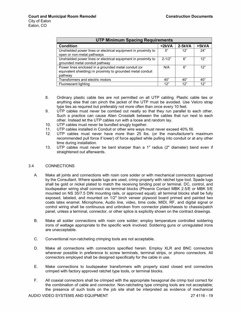
Court and Municipal Room Remodel Construction Documents City of Eaton Eaton, CO
AUDIO VIDEO SYSTEMS AND EQUIPMENT 27 4116 - 19
UTP Minimum Spacing Requirements Condition <2kVA 2-5kVA >5kVA Unshielded power lines or electrical equipment in proximity to open or non-metal pathways
5” 12” 24”
Unshielded power lines or electrical equipment in proximity to grounded metal conduit pathway
2-1/2” 6” 12”
Power lines enclosed in a grounded metal conduit (or equivalent shielding) in proximity to grounded metal conduit pathway
N/A 6” 12”
Transformers and electric motors 40” 40” 40” Fluorescent lighting 12” 12” 12”
8. Ordinary plastic cable ties are not permitted on all UTP cabling. Plastic cable ties or anything else that can pinch the jacket of the UTP must be avoided. Use Velcro strap type ties as required but preferably not more often than once every 10 feet.
9. UTP cables must never be combed out neatly so that they run parallel to each other. Such a practice can cause Alien Crosstalk between the cables that run next to each other. Instead let the UTP cables run with a loose and random lay.
10. UTP cables must never be bundled snugly together. 11. UTP cables installed in Conduit or other wire ways must never exceed 40% fill. 12. UTP cables must never have more than 25 lbs. (or the manufacturer's maximum
recommended pull force if lower) of force applied while pulling into conduit or at any other time during installation.
13. UTP cables must never be bent sharper than a 1" radius (2" diameter) bend even if straightened out afterwards.
3.4 CONNECTIONS
A. Make all joints and connections with rosin core solder or with mechanical connectors approved by the Consultant. Where spade lugs are used, crimp properly with ratchet type tool. Spade lugs shall be gold or nickel plated to match the receiving binding post or terminal. DC, control, and loudspeaker wiring shall connect via terminal blocks (Phoenix Contact MBK 2.5/E or MBK 5/E mounted on NS 35/7.5 DIN mounting rails, or approved equal); all terminal blocks shall be fully exposed, labeled, and mounted on 1/2" birch veneer plywood board primed and painted two coats latex enamel. Microphone, Audio line, video, time code, MIDI, RF, and digital signal or control wiring shall be continuous and unbroken from connector plate/chassis to chassis/patch panel, unless a terminal, connector, or other splice is explicitly shown on the contract drawings.
B. Make all solder connections with rosin core solder; employ temperature controlled soldering irons of wattage appropriate to the specific work involved. Soldering guns or unregulated irons are unacceptable.
C. Conventional non-ratcheting crimping tools are not acceptable.
D. Make all connections with connectors specified herein. Employ XLR and BNC connectors wherever possible in preference to screw terminals, terminal strips, or phono connectors. All connectors employed shall be designed specifically for the cable in use.
E. Make connections to loudspeaker transformers with properly sized closed end connectors crimped with factory approved ratchet type tools, or terminal blocks.
F. All coaxial connectors shall be crimped with the appropriate hexagonal die crimp tool correct for the combination of cable and connector. Non-ratcheting type crimping tools are not acceptable; the presence of such tools on the job site shall be interpreted as evidence of mechanical

Court and Municipal Room Remodel Construction Documents City of Eaton Eaton, CO
AUDIO VIDEO SYSTEMS AND EQUIPMENT 27 4116 - 20
connections incorrectly made, and provide sufficient grounds for rejection of all mechanical connections in the system.
G. "Electrical" adhesive backed tape is not acceptable for any purpose whatsoever. Adhesive cable tie anchors are only acceptable when employed for routing, not support; in any case do not fasten anchors to any equipment chassis.
H. Do not employ connector adapters. Wire nut or "Scotchlock" connectors are not acceptable for any purpose.
3.5 LABELING
A. Provide engraved plastic Lamicoid (or similar) identification labels at the front and rear of all equipment mounted in racks. Install labels in a neat, plumb, square, and permanent manner. Mount labels on the equipment rack, not on the equipment, or on blank rack panels if so directed. Where the rack vertical frame has a slightly recessed mid-section, match label width to the recessed section width. Similarly, provide engraved labels at the rear only of equipment mounted in furniture consoles or frames. Equipment labels should have two items of information; the first identifying the equipment type, i.e., "POWER AMPLIFIER"; and the second showing the wiring diagram code, i.e., "AMP1-01".
B. Unless otherwise noted, engraving on plates, panels, and labels shall be 1/8" high, and the typeface, sans serif. Use white letter fill on dark panels or push-buttons, and black fill on stainless steel or brushed natural aluminum plates or light-colored push-buttons. Fill safety or operational warning labels orange.
C. Embossed labels are not acceptable for any purpose.
D. Label all cables except patch cords at both ends with self-laminating labels. Handwritten labels are not acceptable. Include sample of proposed label system with submittals. Employ an alphanumeric cable code identifying the signal type by letter: microphone = M; data = D; line level analog Audio = A; loudspeaker level = S; video = V; RGBHV = R; RF = F; control = C; intercom = IC; Audio network = N; etc., with a unique identifier for each cable. Locate labels within 2" of the connectors, consistent with regard to orientation, dress, and distance from the connector. For connections to in-room panels or floorboxes, label on cable should match panel engraving. For connections to portable equipment, label on cable should match device engraving.
E. Label each terminal strip with a unique identification code in addition to the numerical labels for each terminal (Phoenix Contact BN series). Show terminal strip codes on the system wiring diagrams.
3.6 SYSTEM STARTUP
A. Preliminary. Verify the following before beginning actual tests and adjustments on the system: 1. All electronic devices are properly grounded. 2. All powered devices have AC power from the proper circuit. All dedicated AC power
circuits are properly wired, phased, and grounded. 3. Insulation and shrink tubing are present where required. 4. Dust, debris, solder splatter, etc. is removed. 5. All cable is dressed, routed, and labeled; all connections are properly made and
consistent with regard to polarity.
B. Grounding System Tests.

Court and Municipal Room Remodel Construction Documents City of Eaton Eaton, CO
AUDIO VIDEO SYSTEMS AND EQUIPMENT 27 4116 - 21
1. Measure the DC resistance between the technical ground in any equipment rack or console and the main building ground. Resistance should be 0.15 ohms or less.
2. Verify that the Owner where applicable has connected the technical ground to building ground at only one location with 4 AWG or larger wire.
3. Measure the DC resistance between the signal ground at any connector plate and the conduit system.
4. Identify and correct any problems if within the A/V System scope of work; notify the Owner if a problem is in a related area of work.
C. System shall be completely free of hum, parasitic oscillation, ground loops, RF interference, and any audible noise and distortion problems.
D. Audio System Tests. 1. Perform the following tests and adjustments, supplying all test equipment required. Set
for slow meter damping and A or Linear weighting as required. Document all tests and complete measurement results including wire number, date, test equipment used, operator, and test results. If any problems are detected in testing, correct the problem, and retest. Make corrections necessary to bring the system(s) into compliance with the specifications. a. Test all cables as installed for shorts between conductors or to building ground and
opens. b. Measure the loop resistance of all loudspeaker cables. c. Measure and record the impedance of each loudspeaker line circuit terminating at
the equipment rack, with loudspeakers connected, over the entire frequency range from 20 Hz to 20 kHz.
d. Adjust the gain of each active device to provide optimum signal-to-noise ratio and 18 to 20 dB headroom. Record input and output levels at each step in the signal chain.
e. Measure and record overall system hum and noise level of each mic or line amplifier with controls set so that -50 dBu microphone input or +4 dBu line level input would drive the system to full amplifier output. Terminate inputs with appropriately sized shielded resistors (150 ohms typical) for this test.
f. Measure and record system electrical frequency response for each input channel through power amplifier output with all filters and equalization bypassed in the DSP. Deviation shall not exceed ± .75dB within the range 20 Hz to 20 kHz.
g. Check system to assure freedom from oscillation or stray RF pickup. Check all inputs without signal and with 500 Hz sine wave driving system to full average output. Detect unwanted signals on oscilloscope at rack termination and over single loudspeakers connected at the farthest distance from the rack for each loudspeaker line.
h. Apply a sinusoidal sweep signal to each loudspeaker system, sweeping from 50 to 5000 Hz at a level 10 dB below full amplifier output, and listen for rattles or objectionable noise. Correct any rattles or noise that is discovered.
i. Check the polarity of all loudspeakers with an electronic polarity checker, and by applying music program or pink noise signal to the system while walking through the transition areas of coverage from one loudspeaker to the next. Transition should be smooth with no apparent shift in source from one loudspeaker to the next.
E. Video System Tests: 1. Verify performance of all video connecting cables, as specified herein. Continuity tests
are not acceptable. Passive paths shall be tested by sweep or multiburst signals. Digital paths shall be tested for BER. Document all tests and complete measurement results including wire number, date, test equipment used, operator, and test results. If any problems are detected in testing, correct the problem, and retest. Replace any defective cable without claim prior to continuing tests.

Court and Municipal Room Remodel Construction Documents City of Eaton Eaton, CO
AUDIO VIDEO SYSTEMS AND EQUIPMENT 27 4116 - 22
2. Perform video signal parameter tests on individual items of equipment, and the work as a whole in accordance with EIA, SMPTE and AES Recommended Practices and other recognized standards as listed under REFERENCES. a. Projection Systems Performance
1) Verify optical performance of projection devices to ANSI Standards using standard test signals connected directly to the device under adjustment.
2) Set devices level and true prior to adjustment, and mark positions for future reference.
3) Complete device’s optical adjustments for focus, centering, geometry and registration prior to applying any electronic corrections.
4) Do not under any circumstances apply corrections at signal sources to compensate for errors in device alignment or adjustment, or timing errors in source material.
5) Set brightness and contrast using reference test signals connected directly to the device. Adjust gray scale and gray scale tracking using ramp or stair step test signals. Set overall brightness and contrast with pluge and white flag signal.
6) Reconnect the projection devices to the system as a whole and verify performance of completed installations. Check that registration has not been affected by timing errors occurring elsewhere on all sources. Verify that source signal levels are consistent, and match the reference levels set by the standard test signals. Correct any deficiencies noted.
7) Record lamp operating hours at conclusion of adjustments. b. CATV System Tests
1) Check all paths and outlets for appropriate compliance with the Performance Standards. Measure levels at all feeder termination points. Compare actual values to design calculations and investigate any difference of more than 2 db, rectify or justify these discrepancies to the satisfaction of the Owner. Document all tests and complete measurement results including wire number, date, test equipment used, operator, and test results. If any problems are detected in testing, correct the problem, and retest.
2) Television Distribution System amplitude standards: a) Minimum visual sync-tip level: +3 dBmV b) Maximum visual sync-tip level: +10 dBmV
3) CATV Cable Testing: Each Trunk Cable line shall be inspected for proper termination: a) Using a standard TV receiver connected to each outlet, observe
picture quality. No visible components of cross modulation (windshield wiper effect), ghosting, noise, or beat interference shall appear on the screen of the receiver tuned to any normal signal.
b) Carrier-to-noise test shall employ an approved field strength meter. Measurements shall be made at the termination of each Trunk Cable and system extremity. With the normal levels in the system, the field strength meter shall be tuned to the picture carrier of each channel in turn and the meter reading noted. Tune the field strength meter to an unused portion of the spectrum within the passband, read the level of remaining noise in the absence of the signal and algebraically add the meter bandwidth correction factor. Record the difference between the two readings. Provide calculations or the manufacturer's data concerning the bandwidth correction factor.
c) System flatness, both forward and reverse, test shall employ an approved high level sweep transmitter receiver pair. Sweep measurements shall be taken at the termination of every branch line termination in the system. Where possible, record sweep results by photographic or computer data logging means.
F. Fiber Optic Testing 1. An OTDR shall be used to check each strand for:

Court and Municipal Room Remodel Construction Documents City of Eaton Eaton, CO
AUDIO VIDEO SYSTEMS AND EQUIPMENT 27 4116 - 23
a. Loss per Unit Length: in dB. b. Splice and Connector Evaluation. c. Possible Fault Location.
2. Test results from the OTDR shall be bound and copied to the owner and their representatives. A strand-per-data file index shall be included.
3. Diligence shall be employed to produce efficient testing: i.e. connectors shall be checked with a microscope to determine whether a bad test run is a bad connector, bad termination, dirt, or a connector needing polishing.
4. Connectors shall remain capped or otherwise protected, when not in use.
G. Network Testing 1. Check all paths and outlets for appropriate compliance with the Performance Standards.
Document all tests and complete measurement results including wire number, date, test equipment used, operator, and test results. If any problems are detected in testing, correct the problem, and retest.
2. Certify all data cables to Category 6 (Draft 9a) or better using a tester capable of 350 MHz measurements such as Fluke DSP-4300, Agilent WireScope 350 or equivalent. a.
H. Report 1. Upon completion of the initial tests and adjustments, submit a written report of tests to the
Consultant along with all documents, diagrams, and record drawings required herein. The Report shall include the date of each test, pertinent conditions such as control settings, etc., test circuit, and test equipment employed. In addition, submit written notification that the installation has been completed in accordance with the requirements of the Contract Documents, and is ready for acceptance testing.
3.7 COMMISSIONING
A. Provide the following test equipment on site and available to the Consultant during commissioning. Assure scaffolding or other temporary access equipment is in place if needed for inspection. 1. Tools, including screwdrivers, pliers, cutters, wire strippers, nut drivers, ratchet crimpers,
heat gun, controlled temperature soldering unit, ladders, flashlights, measuring tapes, electric drills, long and short precision levels, etc.
2. Sound Pressure Level Meter. Meter shall meet ANSI S1.4 1971 Type 1 standards, with an octave band filter set and A, C, and Linear weighting filters. Provide stand for Type 1 microphone, and cables and interfaces to allow it to be used with the sound level meter, time windowed acoustical measurement system, or STI measurement device.
3. Portable Audio Spectrum Analyzer. Handheld unit with graphical display and internal filter sets for standard third octave band response measurements.
4. Sine Wave Generator. Output: +4 dBu, 5 Hz to 50,000 Hz with less than 0.03 % THD into any load.
5. Pink Noise Source. Equal energy per octave bandwidth over the band 20 - 20,000 Hz, ±1 dB (long-term average) at 0 dBu output. Stability: ±2 dB per day.
6. Multimeter. Measurement range, DC to 100,000 Hz, true RMS reading, 100 mV to 300 V, 10 ma to 10A, direct dB reading, frequency counter. Acceptable: Fluke 8060A or equal.
7. Headphones. 8. Programmable Video and Audio Test Generator with SDI/HD-SDI Output.
a. SDI/HD-SDI, RGBHV, component video, S-video, and composite video output. b. Video test patterns including multiple crosshatch patterns, color bars, PLUGE, crop
patterns, geometry, grayscale, and alternating pixel patterns, as well as flat field, window, checkerboard, hum bar, and Patented CTF Contrast Transfer Function patterns with adjustable levels.
c. Selectable output rates, including high resolution computer-video, HDTV, and NTSC/PAL video.

Court and Municipal Room Remodel Construction Documents City of Eaton Eaton, CO
AUDIO VIDEO SYSTEMS AND EQUIPMENT 27 4116 - 24
d. Audio test signals including sine waves, square waves, pink noise, white noise, polarity, frequency sweeps, and sine wave bursts with selectable frequencies and output levels.
e. Acceptable: Extron VTG 400D or equal. 9. Programmable Video and Audio Test Generator with DVI-D/HDMI Output
a. DVI, RGBHV, component video, S-video, and composite video output. b. Displays native resolution of the DVI device when new EDID data is received. c. Video test patterns including multiple crosshatch patterns, color bars, PLUGE, crop
patterns, geometry, grayscale, and alternating pixel patterns, as well as flat field, window, checkerboard, hum bar, and Patented CTF Contrast Transfer Function patterns with adjustable levels.
d. Selectable output rates, including high resolution computer-video, HDTV, and NTSC/PAL video.
e. Audio test signals including sine waves, square waves, pink noise, white noise, polarity, frequency sweeps, and sine wave bursts with selectable frequencies and output levels.
f. Acceptable: Extron VTG 400DVI or equal. 10. Portable Video and Audio Generator and HDMI Analyzer.
a. HDMI Tx/Rx enabled testing of HDMI sink/source devices up to 300MHz. b. Test analog RGB video for PCs. c. HDMI 2.0 4:2:0 Testing. Generator patterns with 4:2:0 pixel encoding with 4K
formats at 60Hz. d. HDCP Verification. Show HDCP test on sink. Show each of the key steps in
authentication. e. EDID Verification. Read sink EDID in human text, run partial EDID compliance
test. f. Aux Channel Monitoring. View hot plug events, EDID exchange, HDCP
transactions and CEC message exchange with sink. g. Status bar showing HDMI Out status. h. Cable & Link Test (loopback). i. 7” color touch screen. j. Acceptable: Quantum Data 780B with Aux Channel Emulation and Network
Analyzer optional feature package. 11. Adapter and test lead kit to allow any of the above to be connected to any circuit or
connector in the system. 12. Wire number machine as used to produce all the wire numbers for the project.
B. Have on site during acceptance testing all parts and components that may be required to make system repairs and minor modifications to bring the system in the Consultant’s opinion into compliance with the Specification. At a minimum these parts shall include: 1. All types of connectors used in the system. Plus, straight and right angle XLR 3, 4, and 5
pin connectors of both sexes, straight and right angle ¼” phone 3 conductor connectors of both sexes, RCA connectors of both sexes, “F” connectors, and BNC connectors, even if not used in the system.
2. All types of wire used in the system. 3. All types of hardware used in the system, plus an assorted hardware kit. 4. All types of fuses used by equipment in the system.
C. Commissioning will include the operation of each major system and any other components deemed necessary. Contractor will assist in this testing and provide the test equipment specified herein. Contractor shall provide at least one technician available for the entire commissioning period, at any time of the day, to assist in tests, adjustments, and final modifications. Furnish all labor, tools, and material required to make any necessary repairs, corrections, or adjustments.
D. In the event the need for further adjustment or work becomes evident during acceptance testing, the Contractor will continue his work with a full labor complement until the system is acceptable, at no addition to the contract price. If approval is delayed because of defective
Court and Municipal Room Remodel Construction Documents City of Eaton Eaton, CO
AUDIO VIDEO SYSTEMS AND EQUIPMENT 27 4116 - 25
equipment, or failure of equipment or installation to meet the requirements of these specifications, the Contractor will pay for additional time and expenses of the Consultant at the Consultant’s standard rate in effect at that time, during and extension of the acceptance testing period.
3.8 CLEANING
A. Remove all unnecessary tools and equipment, unused materials, packing materials, and debris from each area where Work has been completed unless designated for storage.
B. Clean all areas around system equipment and be sure that the inside of each equipment rack is free of wire stripping and other debris.
3.9 INSTRUCTION
A. Provide four (4) hours instruction to Owner designated personnel on the use and operation of the system. This training must be provided in accordance with a schedule acceptable to the Owner. The instructor should be fully knowledgeable and qualified in system operation. The System Reference Manuals should be complete, approved, and on site at the time of this instruction.
B. Upon completion of the Work, the Owner may elect to verify test data as part of the acceptance procedure. Provide personnel and equipment, at the convenience of the Owner, to reasonably demonstrate system performance and to assist with such tests without additional cost to the Owner.
C. Be present at the first formal use of the system.
D. Three months after final acceptance, the Owner reserves the right to direct changes to the control system software. Such changes shall be made without additional cost to the Owner.

Court and Municipal Room Remodel Construction Documents City of Eaton Eaton, CO
AUDIO VIDEO SYSTEMS AND EQUIPMENT 27 4116 - 26
APPENDIX A: A/V EQUIPMENT SCHEDULE
Description Make Model Part Number Device ID Qty
AUDIO EQUIPMENT
CONFERENCE SYSTEM - MASTER STATION w/POWER SUPPLY
SHURE DIS DIS-CCU-US DIS-CCU-US CONF-DSP-01 1
CONFERENCE SYSTEM – 6000 FEATURE LICENSE
SHURE DIS FL6000 FL6000 1
CONFERENCE SYSTEM - MEETING MANAGEMENT SOFTWARE
SHURE DIS SW6000-NEW SW6000-NEW 1
CONFERENCE SYSTEM - DISPLAY APPLICATION
SHURE DIS SW6000-CDA SW6000-CDA 1
CONFERENCE SYSTEM - VOTING SHURE DIS SW6000-VOTE SW6000-VOTE 1
CONFERENCE SYSTEM - CHAIRMAN STATION WITH SCREEN
SHURE DIS DC 6990 P DC 6990 P CONF-CHR-XX 2
CONFERENCE SYSTEM - DELEGATE STATION WITH VOTING
SHURE DIS DM 6680 P DM 6680 P CONF-DLG-XX 6
CONFERENCE SYSTEM - SPEAKER STATION
SHURE DIS DM 6190 P DM 6190 P CONF-POD-XX 6
CONFERENCE SYSTEM - 63cm MICROPHONE
SHURE DIS GM 6525 GM 6525 CONF-MIC-XX 14
CONFERENCE SYSTEM - 63cm MICROPHONE POP FILTER (4 PACK)
SHURE DIS GM 65XX WS GM 65XX WS 4
6.5" PENDANT-MOUNT LOUDSPEAKER QSC AD-P6T AD-P6T SPK1-XX 6
6.5" CEILING-MOUNT LOUDSPEAKER QSC AC-C6T AD-C6T SPK2-XX 2
4-CHANNEL 100W AUDIO AMPLIFIER QSC SPA4-100 SPA4-100 AMP-01 1
8x8x8 (FLEX) DIGITAL SIGNAL PROCESSOR
QSC CORE 110f CORE 110f DSP-01 1
WIRELESS MICROPHONE SYSTEM - HAND HELD
SHURE GLXD24R/B58 GLXD24R/B58 WLESS-01 1
NETWORK SD/USB AUDIO RECORDER DENON DN-700R DN-700R CF-REC-01 1
INFRARED ASSISTED LISTENING SYSTEM
LISTEN LS-93 LS-93 HAS-TX-01 1

Court and Municipal Room Remodel Construction Documents City of Eaton Eaton, CO
AUDIO VIDEO SYSTEMS AND EQUIPMENT 27 4116 - 27
Description Make Model Part Number Device ID Qty
VIDEO EQUIPMENT
50" LED DISPLAY NEC E505 E505 LED50-01 1
50" LED DISPLAY - BACK BOX w/FLANGE AND COVER (WHITE)
CHIEF PAC525FWC PAC525FWC 1
50" LED DISPLAY - ARTICULATING WALL MOUNT BRACKET
CHIEF TS525TU TS525TU 1
50" LED SCREEN - WALL MOUNT MISCELLANEOUS MATERIALS
AV CONTRACTOR
LED INSTALL MATERIALS
LED INSTALL MATERIALS
1
70" LED DISPLAY NEC E705 E705 LED70-01 1
70" LED DISPLAY - BACK BOX w/FLANGE AND COVER (WHITE)
CHIEF PAC525FWC PAC525FWC 1
70" LED DISPLAY - ARTICULATING WALL MOUNT BRACKET
CHIEF PDRUB PDRUB 1
70" LED SCREEN - CEILING MOUNT MISCELLANEOUS MATERIALS
AV CONTRACTOR
LED INSTALL MATERIALS
LED INSTALL MATERIALS
1
15" LED SCREEN (1920x1080) ELO EO45538 EO45538 LED15-XX 9
15" LED SCREEN (1920x1080) - TABLE TOP STAND
ELO 1502L STAND E044162 9
AUDIO VIDEO OVER IP ENCODER - MINIMAL PROPRETARY COMPRESSION
AMX NMX-ENC-N1122 FGN1122-SA AV-ENC1-XX 2
AUDIO VIDEO OVER IP ENCODER - MINIMAL PROPRETARY COMPRESSION w/KVM
AMX NMX-ENC-N1133 FGN1133-SA AV-ENC2-XX 1
AUDIO VIDEO OVER IP ENCODER - MINIMAL PROPRETARY COMPRESSION (DECORA STYLE)
AMX NMX-ENC-N1115-WP-BL
FGN1115-WP-BL AV-ENC3-XX 3
AUDIO VIDEO OVER IP DECODER - MINIMAL PROPRETARY COMPRESSION
AMX NMX-DEC-N1222 FGN1222-SA AV-DEC1-XX 5
AUDIO VIDEO OVER IP DECODER - MINIMAL PROPRETARY COMPRESSION w/KVM
AMX NMX-DEC-N1233 FGN1233-SA AV-DEC2-XX 3
AUDIO VIDEO OVER IP MOUNTING WINGS
AMX NMX-ACC-N9101 FGN9101 7

Court and Municipal Room Remodel Construction Documents City of Eaton Eaton, CO
AUDIO VIDEO SYSTEMS AND EQUIPMENT 27 4116 - 28
Description Make Model Part Number Device ID Qty
AUDIO VIDEO OVER IP RACK SHELF AMX NMX-ACC-N9102 FGN9102 2
1x4 HDMI DISTRIBUTION AMPLIFIER EXTRON DA4 HD 4K 60-1481-01 HDMI-DA4-XX 2
1x4 HDMI DISTRIBUTION AMPLIFIER - SURFACE MOUNT KIT
EXTRON MBU 123 70-212-01 2
BLU-RAY PLAYER DENON DN-500BD DN-500BD BLU-RAY 1
RACK MOUNT VOTING SYSTEM COMPUTER (CUSTOM SPECIFY PRIOR TO ORDER)
DELL OPTIPLEX 3050 MICRO
OPTIPLEX 3050 MICRO
VOTE-CPU-01 1
RACK MOUNT VOTING SYSTEM COMPUTER - SHELF
MID ATLANTIC U2 U2 1
CONTROL AND DATA EQUIPMENT
CONTROL SYSTEM PROCESSOR AMX NX-1200 FG2106-01 CSP-01 1
CONTROL SYSTEM PROCESSOR - RACK MOUNT KIT
AMX AVB-VSTYLE-RMK FG1010-720 1
DUAL DVI-D TOUCH PANEL INTERFACE AMX TPI-PRO-DVI-2 TPI-PRO-DVI-2 TPI-01 1
DUAL DVI-D TOUCH PANEL INTERFACE - 5.4A POWER SUPPLY
AMX PSR5.4 FG423-48 TPI-PS-01 1
28-PORT ETHERNET SWITCH - GIGABIT w/POE (SMART SWITCH)
D-LINK DGS-1210-28P DGS-1210-28P LAN-SW-01 1
24-PORT CAT6 UNSHIELDED PATCH PANEL (PUNCHDOWN) w/DESIGNATION STRIP
BITTREE DSGIGE124D DSGIGE124D LAN-PP-01 1
LAN SWITCH CAT6 PATCH CABLES CABLES2GO #01100 #01100 24
WIRELESS ACCESS POINT w/DHCP WIRELESS SERVER
TRENDNET TEW-812DRU 1
HARDWARE AND RACK EQUIPMENT
35 RU EQUIPMENT RACK - NO REAR DOOR
MID ATLANTIC ERK-3528LRD ERK-3528LRD RACK-01 1
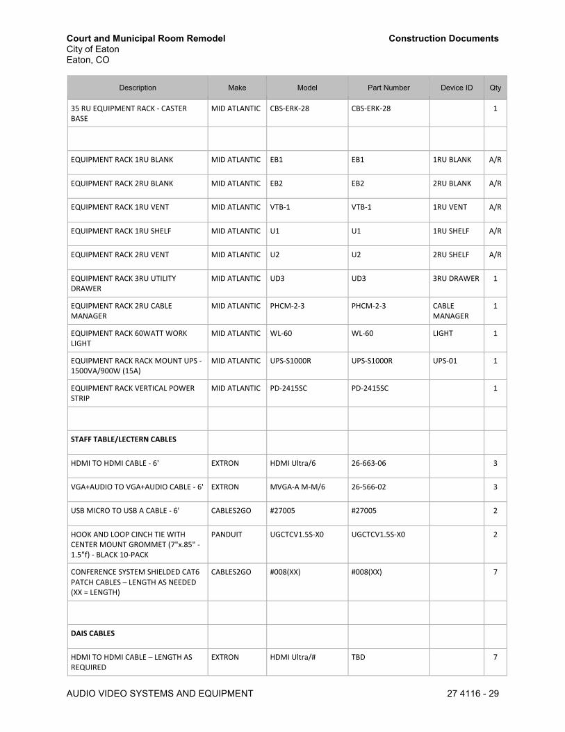
Court and Municipal Room Remodel Construction Documents City of Eaton Eaton, CO
AUDIO VIDEO SYSTEMS AND EQUIPMENT 27 4116 - 29
Description Make Model Part Number Device ID Qty
35 RU EQUIPMENT RACK - CASTER BASE
MID ATLANTIC CBS-ERK-28 CBS-ERK-28 1
EQUIPMENT RACK 1RU BLANK MID ATLANTIC EB1 EB1 1RU BLANK A/R
EQUIPMENT RACK 2RU BLANK MID ATLANTIC EB2 EB2 2RU BLANK A/R
EQUIPMENT RACK 1RU VENT MID ATLANTIC VTB-1 VTB-1 1RU VENT A/R
EQUIPMENT RACK 1RU SHELF MID ATLANTIC U1 U1 1RU SHELF A/R
EQUIPMENT RACK 2RU VENT MID ATLANTIC U2 U2 2RU SHELF A/R
EQUIPMENT RACK 3RU UTILITY DRAWER
MID ATLANTIC UD3 UD3 3RU DRAWER 1
EQUIPMENT RACK 2RU CABLE MANAGER
MID ATLANTIC PHCM-2-3 PHCM-2-3 CABLE MANAGER
1
EQUIPMENT RACK 60WATT WORK LIGHT
MID ATLANTIC WL-60 WL-60 LIGHT 1
EQUIPMENT RACK RACK MOUNT UPS - 1500VA/900W (15A)
MID ATLANTIC UPS-S1000R UPS-S1000R UPS-01 1
EQUIPMENT RACK VERTICAL POWER STRIP
MID ATLANTIC PD-2415SC PD-2415SC 1
STAFF TABLE/LECTERN CABLES
HDMI TO HDMI CABLE - 6' EXTRON HDMI Ultra/6 26-663-06 3
VGA+AUDIO TO VGA+AUDIO CABLE - 6' EXTRON MVGA-A M-M/6 26-566-02 3
USB MICRO TO USB A CABLE - 6' CABLES2GO #27005 #27005 2
HOOK AND LOOP CINCH TIE WITH CENTER MOUNT GROMMET (7"x.85" - 1.5"f) - BLACK 10-PACK
PANDUIT UGCTCV1.5S-X0 UGCTCV1.5S-X0 2
CONFERENCE SYSTEM SHIELDED CAT6 PATCH CABLES – LENGTH AS NEEDED (XX = LENGTH)
CABLES2GO #008(XX) #008(XX) 7
DAIS CABLES
HDMI TO HDMI CABLE – LENGTH AS REQUIRED
EXTRON HDMI Ultra/# TBD 7
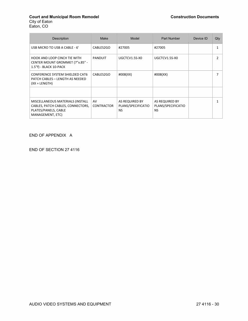
Court and Municipal Room Remodel Construction Documents City of Eaton Eaton, CO
AUDIO VIDEO SYSTEMS AND EQUIPMENT 27 4116 - 30
Description Make Model Part Number Device ID Qty
USB MICRO TO USB A CABLE - 6' CABLES2GO #27005 #27005 1
HOOK AND LOOP CINCH TIE WITH CENTER MOUNT GROMMET (7"x.85" - 1.5"f) - BLACK 10-PACK
PANDUIT UGCTCV1.5S-X0 UGCTCV1.5S-X0 2
CONFERENCE SYSTEM SHIELDED CAT6 PATCH CABLES – LENGTH AS NEEDED (XX = LENGTH)
CABLES2GO #008(XX) #008(XX) 7
MISCELLANEOUS MATERIALS (INSTALL CABLES, PATCH CABLES, CONNECTORS, PLATES/PANELS, CABLE MANAGEMENT, ETC)
AV CONTRACTOR
AS REQUIRED BY PLANS/SPECIFICATIONS
AS REQUIRED BY PLANS/SPECIFICATIONS
1
END OF APPENDIX A
END OF SECTION 27 4116

Court and Municipal Room Remodel Construction Documents City of Eaton Eaton, CO
AUDIO DSP SYSTEMS CONFIGURATION 27 4160 - 1
SECTION 27 4160 – AUDIO DSP SYSTEMS CONFIGURATION
PART 1 - GENERAL
1.1 CONTRACT DOCUMENTS
A. The General and Special Conditions are hereby made a part of this Section. Where requirements of this Section are at odds with requirements stated in any Special or Supplementary Conditions, the more stringent requirements shall apply.
B. The Contract Documents are complementary and are intended to include or imply all items required for the proper execution and completion of the work. Any item or work required by the Specification or other portion of the Contract Documents, but not shown on the drawings, or shown on the drawings but not described in the Specification, shall be provided and installed by the Contractor as if shown or mentioned in both.
C. The Consultant may furnish additional instruction or clarification necessary for the proper execution of the work. Instructions or clarifications shall be consistent with the Contract Documents, or agreed upon modifications thereof, and inferable therefrom. In giving instruction or clarification, only the Contracting Officer shall have the authority to make minor changes in the work that will not entail an increase in the Contract price or time.
D. Copies of drawings and specifications regardless of how furnished are the property of the Owner, and are not to be used on any other work or project. No contract documents may be released for publication or to any other party without the written consent of the Owner and Consultant. All references to “the Owner” in this document refer to City of Eaton, CO.
1.2 GOVERNING CLAUSE
A. For the sake of brevity these specifications omit phrases such as "Contractor shall furnish and install," "unless otherwise noted or specified," etc.; nevertheless, the requirements of the specifications are mandatory, and these phrases shall be inferred. The mention of materials and operations implies the Contractor shall furnish and install such materials and perform such operations to the overall standards set by the Contract Documents. Exceptions are noted herein or shown on the drawings.
B. In the event that a Consultant is not a participant in this project after award of contract, all references to “Consultant” in this document shall be replaced with “Owner”.
1.3 DEFINITIONS
A. Configuration: the software and firmware programming that defines and creates the functionality, levels, presets, and settings of DSP devices.
B. Configure: To define functionality, levels, presets, and settings of DSP device(s) using software and/or firmware.
C. Programmer: Contractor personnel engaged in developing the configuration of DSP systems.
D. DSP: Digital Signal Processing, or Digital Signal Processor.
E. AEC: Acoustic Echo Cancellation

Court and Municipal Room Remodel Construction Documents City of Eaton Eaton, CO
AUDIO DSP SYSTEMS CONFIGURATION 27 4160 - 2
F. Fixed Architecture: Referring to DSP software providing fixed processing paths with adjustable processing objects in a predetermined sequence.
G. Open Architecture: Referring to DSP software providing infinitely variable Programmer selected processing paths with adjustable processing objects arranged in any sequence deemed appropriate by Programmer.
1.4 QUALIFICATIONS
A. Refer to Section 27 4116 for additional requirements.
B. Training: Programmer shall have received manufacturer-provided and/or manufacturer approved training in the configuration of the DSP systems being provided.
C. Certification: Programmer shall hold the highest applicable manufacturer programming certification(s) offered by the manufacturer(s) of the DSP hardware specified for the project. 1. For Biamp: Audia/Tesira Certification 2. For BSS: Architectural Media Systems Advanced DSP 3. For QSC: Q-Sys Level 2 4. For Symetrix: Symnet Composer Certification
D. Submittal: Certification certificate shall be submitted with DSP submittals.
1.5 SCOPE
A. Refer to Section 27 4116 for additional project scope information.
B. Contractor Responsibility: Program and configure fully functional digital signal processor (DSP).
C. IP Interface: Contractor shall program and configure IP-based control software to allow Owner to remotely control DSP functions as part of this work using IP-based DSP device.
D. Software: All versions shall be current as of date of substantial completion.
1.6 RELATED WORK
A. Section 27 4116 – Audio Video Systems and Equipment
B. Section 27 4170 – Audio Video Control System Programming
1.7 NETWORK CONFIGURATION
A. Where connection between components or control features are accomplished over a LAN (either dedicated AV or Owner’s), Contractor shall follow Audio DSP manufacturer’s guidelines for setup and configuration.
1.8 IT COORDINATION
A. General: Where connection between components or control features are accomplished over the Owner’s LAN, Contractor shall coordinate with Owner’s IT department for IP addresses, firewall access, and other issues pertaining to successful integration.

Court and Municipal Room Remodel Construction Documents City of Eaton Eaton, CO
AUDIO DSP SYSTEMS CONFIGURATION 27 4160 - 3
B. Permission: It is Contractor’s responsibility to obtain necessary information and permissions to implement their system. Any delays or problems with gathering information or coordinating access to the LAN or WAN shall be brought to Consultant immediately for resolution.
1.9 PROCESS
A. General: Contractor should expect and permit time for an iterative process whereby multiple smaller submissions are made for review and approval. 1. Initial Planning:
a. Contactor shall identify project scope, requirements, and any potential issues at a high level but with enough detail that work and direction can be evaluated and approved.
2. Development a. Contractor shall deliver a working DSP framework that addresses the items determined in
the initial planning stage and note any non-functional requirements. 3. Construction
a. Incrementally fills-in the architecture with finished programming produced from initial planning, development, and testing of the functional requirements.
4. Deployment a. Delivers/deploys the system into the operating environment and provides full operational
testing.
1.10 PRE-CONSTRUCTION SUBMITTALS
A. Refer to Section 27 4116 for additional requirements.
B. DSP programmer shall provide a Supplemental AV Network Configuration Narrative for review that details the IP configuration and settings for the Audio DSP configuration and related devices. This shall include but not be limited to all IP configurations and settings, proposed (or dovetailed into project) IP address scheme, proposed (or dovetailed into project) VLANs, and proof of compliance with manufacturer’s recommended network settings.
C. Contractor shall supply the DSP configuration file for all audio digital signal processors (DSP), authored in DSP manufacturer’s most current software for review and approval.
D. Copy of or web link to manufacturer download page of configuration software for accessing configuration software.
E. Processor power required of DSP shall not exceed 95% total processing capacity. 1. If processing power required exceeds available processing power, Contractor shall immediately
notify Consultant during pre-installation phase.
F. Layouts of physical and virtual user controls in graphical format. This shall include: 1. Engraved buttons and overlays 2. Machine-printed adhesive labels 3. Graphical user interfaces for touch panels or web interfaces
G. Version: Submitted software shall be identical version used to create Audio DSP configuration.
H. Contractor shall make changes as requested by Consultant in pre-construction submittal review.
1.11 FUNCTIONAL REQUIREMENTS
A. Functions: The DSP shall be configured to provide (not all may apply): 1. Pre-amplification
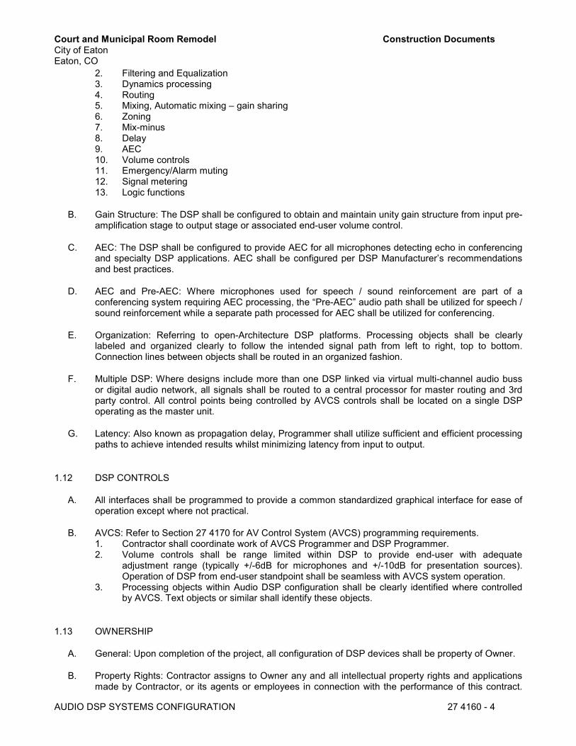
Court and Municipal Room Remodel Construction Documents City of Eaton Eaton, CO
AUDIO DSP SYSTEMS CONFIGURATION 27 4160 - 4
2. Filtering and Equalization 3. Dynamics processing 4. Routing 5. Mixing, Automatic mixing – gain sharing 6. Zoning 7. Mix-minus 8. Delay 9. AEC 10. Volume controls 11. Emergency/Alarm muting 12. Signal metering 13. Logic functions
B. Gain Structure: The DSP shall be configured to obtain and maintain unity gain structure from input pre-amplification stage to output stage or associated end-user volume control.
C. AEC: The DSP shall be configured to provide AEC for all microphones detecting echo in conferencing and specialty DSP applications. AEC shall be configured per DSP Manufacturer’s recommendations and best practices.
D. AEC and Pre-AEC: Where microphones used for speech / sound reinforcement are part of a conferencing system requiring AEC processing, the “Pre-AEC” audio path shall be utilized for speech / sound reinforcement while a separate path processed for AEC shall be utilized for conferencing.
E. Organization: Referring to open-Architecture DSP platforms. Processing objects shall be clearly labeled and organized clearly to follow the intended signal path from left to right, top to bottom. Connection lines between objects shall be routed in an organized fashion.
F. Multiple DSP: Where designs include more than one DSP linked via virtual multi-channel audio buss or digital audio network, all signals shall be routed to a central processor for master routing and 3rd party control. All control points being controlled by AVCS controls shall be located on a single DSP operating as the master unit.
G. Latency: Also known as propagation delay, Programmer shall utilize sufficient and efficient processing paths to achieve intended results whilst minimizing latency from input to output.
1.12 DSP CONTROLS
A. All interfaces shall be programmed to provide a common standardized graphical interface for ease of operation except where not practical.
B. AVCS: Refer to Section 27 4170 for AV Control System (AVCS) programming requirements. 1. Contractor shall coordinate work of AVCS Programmer and DSP Programmer. 2. Volume controls shall be range limited within DSP to provide end-user with adequate
adjustment range (typically +/-6dB for microphones and +/-10dB for presentation sources). Operation of DSP from end-user standpoint shall be seamless with AVCS system operation.
3. Processing objects within Audio DSP configuration shall be clearly identified where controlled by AVCS. Text objects or similar shall identify these objects.
1.13 OWNERSHIP
A. General: Upon completion of the project, all configuration of DSP devices shall be property of Owner.
B. Property Rights: Contractor assigns to Owner any and all intellectual property rights and applications made by Contractor, or its agents or employees in connection with the performance of this contract.

Court and Municipal Room Remodel Construction Documents City of Eaton Eaton, CO
AUDIO DSP SYSTEMS CONFIGURATION 27 4160 - 5
Contractor also acknowledges and agrees that services rendered in connection with the performance of this contract shall be a “work made for hire” within the meaning of Section 201 inventions of the Copyright Law of 1976.
C. Passwords: Contractor shall not use any passwords to prevent access to Audio DSP configuration files in submittal formats.
1.14 QUALITY ASSURANCE
A. Contractor shall verify complete functionality prior to scheduling inspections with Consultant, including but not limited to: 1. DSP control functionality, verification of presets, volume controls, mute controls, etc. 2. Stable operation, completely free of feedback and distortion throughout entire range of available
DSP controls. 3. Correct routing of all signals to intended destinations. 4. Unity gain structure. 5. Output transducer (speaker) protection processing functionality. 6. AEC functionality.
1.15 UPGRADES 1. Firmware: Firmware upgrades shall be dated the same as Date of Acceptance. Contractor shall
upgrade firmware and software as necessary during project so that latest versions are installed as of Date of Acceptance.
PART 2 - PRODUCTS
2.1 SUBSTITUTIONS
A. Unless noted otherwise, products in this section and associated sections are intended as the basis of design and are not open to substitutions unless compelling technical reasons are provided.
2.2 PRODUCT SPECIFICATIONS
A. General: Contractor shall provide configuration services for all Audio DSP products identified in Section 27 4116 AUDIO VIDEO SYSTEMS AND EQUIPMENT.
B. Hardware: Contractor shall supply any equipment, accessories, cable, and connectors necessary for system to operate according to stated functional requirements, whether or not said products are named in Section 27 4116 AUDIO VIDEO SYSTEMS AND EQUIPMENT.
C. Software: Contractor shall utilize Manufacturers official current version of configuration software. Special exemption may be obtained from Consultant if current version contains known issues. In such event, the version immediately preceding shall be utilized.
D. Control Interfaces: shall be labeled or configured with graphical user interface as appropriate.

Court and Municipal Room Remodel Construction Documents City of Eaton Eaton, CO
AUDIO DSP SYSTEMS CONFIGURATION 27 4160 - 6
PART 3 - EXECUTION
3.1 TESTING
A. Refer to Section 27 4116 for additional requirements.
3.2 TRAINING
A. Refer to Section 27 4116 for additional requirements.
3.3 WARRANTY
A. Refer to Section 27 4116 for additional requirements.
END OF SECTION 27 4160

Court and Municipal Room Remodel Construction Documents City of Eaton Eaton, CO
AUDIO VIDEO CONTROL SYSTEMS PROGRAMMING 27 4170 - 1
SECTION 27 4170 – AUDIO VIDEO CONTROL SYSTEMS PROGRAMMING
PART 1 - GENERAL
1.1 CONTRACT DOCUMENTS
A. The General and Special Conditions are hereby made a part of this Section. Where requirements of this Section are at odds with requirements stated in any Special or Supplementary Conditions, the more stringent requirements shall apply.
B. The Contract Documents are complementary and are intended to include or imply all items required for the proper execution and completion of the work. Any item or work required by the Specification or other portion of the Contract Documents, but not shown on the drawings, or shown on the drawings but not described in the Specification, shall be provided and installed by the Contractor as if shown or mentioned in both.
C. The Consultant may furnish additional instruction or clarification necessary for the proper execution of the work. Instructions or clarifications shall be consistent with the Contract Documents, or agreed upon modifications thereof, and inferable therefrom. In giving instruction or clarification, only the Contracting Officer shall have the authority to make minor changes in the work that will not entail an increase in the Contract price or time.
D. Copies of drawings and specifications regardless of how furnished are the property of the Owner, and are not to be used on any other work or project. No contract documents may be released for publication or to any other party without the written consent of the Owner and Consultant. All references to “the Owner” in this document refer to City of Eaton, CO.
1.2 GOVERNING CLAUSE
A. For the sake of brevity these specifications omit phrases such as "Contractor shall furnish and install," "unless otherwise noted or specified," etc.; nevertheless, the requirements of the specifications are mandatory, and these phrases shall be inferred. The mention of materials and operations implies the Contractor shall furnish and install such materials and perform such operations to the overall standards set by the Contract Documents. Exceptions are noted herein or shown on the drawings.
B. In the event that a Consultant is not a participant in this project after award of contract, all references to “Consultant” in this document shall be replaced with “Owner”.
1.3 DEFINITIONS
A. Configuration: the software and firmware programming that defines and creates the control functionality for Audio Video devices.
B. Configure: To define functionality, controls, and settings of Audio Video device(s) using software and/or firmware.
C. Programmer: Contractor personnel engaged in developing the configuration of Audio Video Control Systems.
D. CSP: Control System Processor.

Court and Municipal Room Remodel Construction Documents City of Eaton Eaton, CO
AUDIO VIDEO CONTROL SYSTEMS PROGRAMMING 27 4170 - 2
1.4 QUALIFICATIONS
A. Refer to Section 27 4116 additional requirements.
B. Training: Programmer shall have received manufacturer-provided and/or manufacturer approved training in the configuration of the AVCS systems being provided.
C. Certification: Programmer shall hold the applicable manufacturer programming certification(s) or be an authorized independent programmer of the ICS specified for the project. 1. For AMX: AMX Certified Expert (ACE Programming Expert) 2. For Crestron: Crestron Certified Programmer 3. For Extron: Extron Control Professional (ECP) 4. Or approved equal
D. Submittal: Certification certificate shall be submitted with AVCS submittals.
1.5 SCOPE
A. Refer to Section 27 4116 for additional project scope information.
B. Contractor Responsibility: Program and configure fully functional Audio Video Control System (AVCS).
C. IP Interface: Contractor shall program and configure IP-based control software to allow Owner to remotely control room functions as part of this work using IP-based control device.
D. Software: All versions shall be current as of date of substantial completion.
1.6 RELATED WORK
A. Section 27 4116 – Audio Video Systems and Equipment
B. Section 27 4160 – Audio DSP Configuration
1.7 NETWORK CONFIGURATION
A. Where connection between components or control features are accomplished over a LAN (either dedicated AV or Owner’s), Contractor shall follow Audio DSP manufacturer’s guidelines for setup and configuration.
1.8 IT COORDINATION
A. General: Where connection between components or control features are accomplished over the Owner’s LAN, Contractor shall coordinate with Owner’s IT department for IP/MAC addresses, firewall access, and other issues pertaining to successful integration.
B. Permission: It is the Contractor’s responsibility to obtain necessary information and permissions to implement their system. Any delays or problems with gathering information or coordinating access to the LAN or WAN shall be brought to Consultant immediately for resolution.

Court and Municipal Room Remodel Construction Documents City of Eaton Eaton, CO
AUDIO VIDEO CONTROL SYSTEMS PROGRAMMING 27 4170 - 3
1.9 PRE-CONSTRUCTION SUBMITTALS
A. Refer to Section 27 4116 for additional requirements.
B. AVCS programmer shall provide a Supplemental AV Network Configuration Narrative for review that details the IP configuration and settings for the control system configuration and related devices. This shall include but not be limited to all IP configurations and settings, proposed (or dovetailed into project) IP address scheme, proposed (or dovetailed into project) VLANs, and proof of compliance with manufacturer’s recommended network settings.
C. This submittal shall be in advance of any control system coding being performed. No claims for additional compensation shall be granted for work completed prior to touch panel acceptance if changes are required.
D. Layouts of physical and virtual user controls in graphical format. This shall include: 1. Engraved buttons and overlays 2. Machine-printed adhesive labels 3. Graphical user interfaces for touch panels or web interfaces 4. Descriptive write-up of function(s) of each button for each page.
E. Copy of manufacturer configuration software, or link to manufacturer website download page for accessing configuration software. 1. Version: Submitted software shall be identical version used to create integrated control system
configuration.
F. Audio Video Control System review shall be done via Skype/WebEx conference with Consultant.
G. Contractor shall make changes as requested by Consultant in pre-construction submittal review.
1.10 FUNCTIONAL REQUIREMENTS
A. Functions: The AVCS shall be configured to provide (not all may apply): 1. System On/Off 2. Source Selection 3. Volume Controls
a. General b. Microphone Sources c. Line Sources
4. Volume Mutes a. General b. Microphone Sources
5. Room Controls a. Projection Screen b. Lighting c. Window Shades
6. Device Controls 7. Telephone/VoIP Controls 8. Warnings/Alerts
1.11 AESTHETIC REQUIRMENTS
A. Printing: Button labels shall be engraved where applicable, or machine-printed where no engraved button/bezel is available. Handwritten labels are not acceptable.

Court and Municipal Room Remodel Construction Documents City of Eaton Eaton, CO
AUDIO VIDEO CONTROL SYSTEMS PROGRAMMING 27 4170 - 4
B. Graphics: Icons and graphic representations of equipment and functions shall be crisp, sharp, and easy to identify. Icons shall be used wherever possible.
C. Text: AVCS screens shall not use uncommon abbreviations. Text shall be sans serif and shall be sized to be clearly readable.
1.12 CONTROLS
A. All interfaces shall be programmed to provide a common standardized graphical interface for ease of operation except where not practical.
B. AVCS: Refer to Section 27 4160 for Audio DSP System programming requirements. 1. Contractor shall coordinate work of DSP Programmer and AVCS Programmer.
1.13 OWNERSHIP
A. General: Upon completion of the project, all programming and configuration of control hardware, touch panels, and other devices shall be property of Owner.
B. Property Rights: Contractor assigns to Owner any and all intellectual property rights and applications made by Contractor, or its agents or employees in connection with the performance of this contract. Contractor also acknowledges and agrees that services rendered in connection with the performance of this contract shall be a “work made for hire” within the meaning of Section 201 inventions of the Copyright Law of 1976.
C. No Passwords: Contractor shall not use any passwords to prevent access to code files except as specified herein.
1.14 QUALITY ASSURANCE
A. Contractor shall verify complete functionality prior to scheduling inspections with Consultant, including but not limited to: 1. AVCS control functionality, verification of presets, volume controls, mute controls, etc. 2. Stable operation, completely free of feedback and distortion throughout entire range of available
AVCS controls. 3. Correct routing of all signals to intended destinations. 4. Unity gain structure. 5. Output transducer (speaker) protection processing functionality. 6. AEC functionality.
1.15 UPGRADES 1. Firmware: Firmware upgrades shall be dated the same as Date of Acceptance. Contractor shall
upgrade firmware and software as necessary during project so that latest versions are installed as of Date of Acceptance.

Court and Municipal Room Remodel Construction Documents City of Eaton Eaton, CO
AUDIO VIDEO CONTROL SYSTEMS PROGRAMMING 27 4170 - 5
PART 2 - PRODUCTS
2.1 SUBSTITUTIONS
A. Unless noted otherwise, products in this section and associated sections are intended as the basis of design and are not open to substitutions unless compelling technical reasons are provided.
2.2 PRODUCT SPECIFICATIONS
A. General: Contractor shall provide programming for products as identified in Section 27 4116.
B. Hardware: Contractor shall supply equipment, accessories, cable, and connectors necessary for system to operate according to stated functional requirements, whether or not said products are named in Appendix A. If Contractor wishes major additions to be given special consideration, part numbers, quantities, and line item pricing may be listed under Exceptions on the Bid/Proposal form.
PART 3 - EXECUTION
3.1 TESTING
A. Refer to Section 27 4116 for additional requirements.
B. General: Contractor shall check the functionality and programming of system prior to substantial completion inspection. Any programming bugs shall be fixed prior to that inspection.
3.2 TRAINING
A. Refer to Section 27 4116 for additional requirements.
3.3 WARRANTY
A. Refer to Section 27 4116 for additional requirements.
END OF SECTION 27 4170