course: introduction to electrical machines part 3 prof elisete ternes pereira, phd
TRANSCRIPT

COURSE:
INTRODUCTION TO ELECTRICAL MACHINES
PART 3
Prof Elisete Ternes Pereira, PhD

INTRODUCTION TO
ROTATING MACHINES
ROTATING MACHINESINTRODUCTION
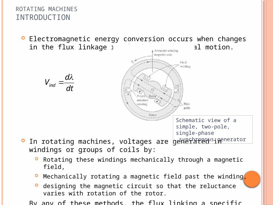
Electromagnetic energy conversion occurs when changes in the flux linkage result from mechanical motion.
In rotating machines, voltages are generated in windings or groups of coils by: Rotating these windings mechanically through a magnetic field, Mechanically rotating a magnetic field past the winding, designing the magnetic circuit so that the reluctance varies with rotation of the rotor.
By any of these methods, the flux linking a specific coil is changed cyclically, and a time-varying voltage is generated.
dt
dVind
Schematic view of a simple, two-pole, single-phase synchronous generator.

ROTATING MACHINESINTRODUCTION
A set of such coils connected together is typically referred to as an armature winding.
In general, the term armature winding is used to refer to a winding on a rotating machine which carry ac currents.
In ac machines such as synchronous or induction machines, the armature winding is typically on the stationary portion of the motor referred to as the stator, in which case these windings may also be referred to as stator windings.
In a dc machine, the armature winding is found on the rotating member, referred to as the rotor.
the armature winding of a dc machine consists of many coils connected together to form a closed loop.
Simple, two-pole, single-phase synchronous generator.

ROTATING MACHINESINTRODUCTION
In some machines, such as variable reluctance machines and stepper motors, there are no windings on the rotor.
Operation of these machines depends on the nonuniformity of air-gap reluctance associated with variations in rotor position in conjunction with time-varying currents applied to their stator windings.
Rotating electric machines take many forms and are known by many names: dc, synchronous, permanent-magnet, induction, variable reluctance, hysteresis, brushless, and so on.
Although these machines appear to be quite dissimilar, their behavior are quite similar, and it is often helpful to think of them in terms of the same physical picture.

AC & DC MACHINES - INTRODUCTION
INTRODUCTION TO ROTATING MACHINES

INTRODUCTION TOAC MACHINES
Traditional ac machines fall into one of two categories:
Synchronous machines: rotor-winding currents are supplied directly from the stationary frame through a rotating contact.
Induction machines: rotor currents are induced in the rotor windings by a combination of the time-variation of the stator currents and the motion of the rotor relative to the stator.

INTRODUCTION TOSynchronous Machines
With rare exceptions, the armature winding of a synchronous machine is on the stator, and the field winding is on the rotor,
The field winding is excited by direct current conducted to it by means of stationary carbon brushes which contact rotating slip rings or collector rings.
o Synchronous machines: Consider the very much simplified salient-pole ac synchronous generator:
o The field-winding of this machine produces a single pair of magnetic poles (similar to that of a bar magnet), and hence this machine is referred to as a two-pole machine.

The armature winding, consisting here of only a single coil of N turns, is indicated in cross section by the two coil sides a and -a .
The conductors forming these coil sides are parallel to the shaft of the machine and are connected in series by end connections (not shown in the figure).
The rotor is turned at a constant speed by a source of mechanical power connected to its shaft.
The armature winding is assumed to be open-circuited and hence the flux in this machine is produced by the field winding alone.
Flux paths are shown schematically by dashed lines.
INTRODUCTION TOSynchronous Machines

An idealized analysis would assume a sinusoidal distribution of magnetic flux in the air gap.
The resultant radial distribution of air-gap flux density B is shown in the figure bellow as a function of the spatial angle a (measured with respect to the magnetic axis of the armature winding) around the rotor periphery.
(a) Space distribution of flux density and(b) corresponding waveform of the generated voltage for the single-phase generator
INTRODUCTION TOSynchronous Machines

As the rotor rotates, the flux-linkages of the armature winding change with time.
Under the assumption of a sinusoidal flux distribution and constant rotor speed, the resulting coil voltage will be sinusoidal in time.
The coil voltage passes through a complete cycle for each revolution of the two-pole machine.
Its frequency in cycles per second (Hz) is the same as the speed of the rotor in revolutions per second: the electric frequency of the generated voltage is synchronized with the mechanical speed, and this is the reason for the designation "synchronous" machine.
Thus a two-pole synchronous machine must revolve at 3600 revolutions per minute to produce a 60-Hz voltage.
INTRODUCTION TOSynchronous Machines

A great many synchronous machines have more than two poles. The figure shows a four-pole single-phase generator.
The field coils are connected so that the poles are of alternate polarity.
The span of each coil is one wavelength of flux.
The generated voltage now goes through two complete cycles per revolution of the rotor.
The frequency in hertz will be twice the speed in revolutions per second.
There are two complete wavelengths, or cycles, in the flux distribution around the periphery.
The armature winding now consists of two coils a1, -a1 and a2, -a2 connected in series.
INTRODUCTION TOSynchronous Machines

o When a machine has more than two poles, it is convenient to concentrate on a single pair of poles and to recognize that the electric, magnetic, and mechanical conditions associated with every other pole pair are repetitions of those for the pair under consideration.
o For this reason it is convenient to express angles in electrical degrees or electrical radians rather than in physical units.
o One pair of poles in a multipole machine or one cycle of flux distribution equals 360 electrical degrees or 2 electrical radians.
o Since there are (poles/2) complete wavelengths, or cycles, in one complete revolution, it follows that:
aae
pole2
Where: angle in electrical units
spatial angle.
This same relationship applies to all angular measurements in a multipole machine; their values in electrical units will be equal to (poles/2) times their actual spatial values.
aea
INTRODUCTION TOSynchronous Machines

o The coil voltage of a multipole machine passes through a complete cycle every (poles/2) times each revolution.
o The electrical frequency fe of the voltage generated in a synchronous machine is therefore:
o Where: o n the mechanical speed in revolutions per minute, and hence n/60 is the speed in
revolutions per second.
o The electrical frequency of the generated voltage in radians per second is:
o Where:o m is the mechanical speed in radians per second.
Hznpole
fe 602
sec/2
radpole
me
INTRODUCTION TOSynchronous Machines

o The rotors in the 2 figures below have salient, or projecting, poles with concentrated windings.
o Figure below shows a nonsalient-pole, or cylindrical rotor.
o The field winding is a two-pole distributed winding; the coil sides are distributed in multiple slots around the rotor periphery and arranged to produce an approximately sinusoidal distribution of radial air-gap flux.
INTRODUCTION TOSynchronous Machines

o A salient-pole construction is characteristic of hydroelectric generators because hydraulic turbines operate at relatively low speeds, and hence a relatively large number of poles is required to produce the desired frequency; the salient-pole construction is better adapted mechanically to this situation.
o Steam turbines and gas turbines, however, operate best at relatively high speeds, and turbine-driven alternators or turbine generators are commonly two- or four-pole cylindrical-rotor machines.
Hznpole
fe 602
INTRODUCTION TOSynchronous Machines

o Most of the world's power systems are three-phase systems and, as a result, with very few exceptions, synchronous generators are three-phase machines.
o For the production of a set of three voltages phase-displaced by 120 electrical degrees in time, a minimum of three coils phase-displaced 120 electrical degrees in space must be used.
o A simplified schematic of a three-phase, two-pole machine with one coil per phase:
o The three phases are designated by the letters a, b, and c.
INTRODUCTION TOSynchronous Machines

o In an elementary three-phase, four-pole machine, a minimum of two such sets of coils must be used, as illustrated;
o in an elementary multipole machine, the minimum number of coils sets is given by one half the number of poles.
o The two coils in each phase are connected in series so that their voltages add, and the three phases may then be either Y- or -connected.
INTRODUCTION TOSynchronous Machines

o The figure shows how the coils may be interconnected to form a Y connection.
o Since the voltages in the coils of each phase are identical, a parallel connection is also possible, e.g., coil (a, -a) in parallel with coil (a', -a'), and so on.
INTRODUCTION TOSynchronous Machines

o When a synchronous generator supplies electric power to a load, the armature current creates a magnetic flux wave in the air gap which rotates at synchronous speed,
o This flux reacts with the flux created by the field current, and electromechanical torque results from the tendency of these two magnetic fields to align.
o In a generator this torque opposes rotation, and mechanical torque must be applied from the prime mover to sustain rotation.
o This electromechanical torque is the mechanism through which the synchronous generator converts mechanical to electric energy.
INTRODUCTION TOSynchronous Machines

o The counterpart of the synchronous generator is the synchronous motor.
o A cutaway view of a three-phase, 60-Hz synchronous motor is shown in the figure:
o Alternating current is supplied to the armature winding on the stator, and dc excitation is supplied to the field winding on the rotor.
o The magnetic field produced by the armature currents rotates at synchronous speed.
o To produce a steady electromechanical torque, the magnetic fields of the stator and rotor must be constant in amplitude and stationary with respect to each other.
INTRODUCTION TOSynchronous Machines

o In a synchronous motor, the steady-state speed is determined by the number of poles and the frequency of the armature current.
o Thus a synchronous motor operated from a constant-frequency ac source will operate at a constant steady-state speed.
o In a motor the electromechanical torque is in the direction of rotation and balances the opposing torque required to drive the mechanical load.
o The flux produced by currents in the armature of a synchronous motor rotates ahead of that produced by the field, thus pulling on the field (and hence on the rotor) and doing work.
o This is the opposite of the situation in a synchronous generator, where the field does work as its flux pulls on that of the armature, which is lagging behind.
o In both generators and motors, an electromechanical torque and a rotational voltage are produced.
o These are the essential phenomena for electromechanical energy conversion.
INTRODUCTION TOSynchronous Machines

In the Induction Machines, like the synchronous machine, the stator winding is excited with alternating currents.
But, Rotor currents are produced by induction, i.e., transformer action.
The induction machine may be regarded as a generalized transformer in which electric power is transformed between rotor and stator together with a change of frequency and a flow of mechanical power.
In contrast to a synchronous machine in which a field winding on the rotor
is excited with dc current, alternating currents flow in the rotor windings of an induction machine.
In induction machines, alternating currents are applied directly to the stator windings.
INTRODUCTION TOInduction Machines

Although the induction motor is the most common of all motors, it is seldom used as a generator;
Its performance characteristics as a generator are unsatisfactory for most applications, although in recent years it has been found to be well suited for wind-power applications.
The induction machine may also be used as a frequency changer.
INTRODUCTION TOInduction Machines
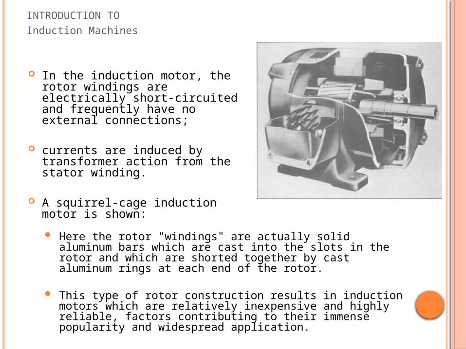
In the induction motor, the rotor windings are electrically short-circuited and frequently have no external connections;
currents are induced by transformer action from the stator winding.
A squirrel-cage induction motor is shown:
Here the rotor "windings" are actually solid aluminum bars which are cast into the slots in the rotor and which are shorted together by cast aluminum rings at each end of the rotor.
This type of rotor construction results in induction motors which are relatively inexpensive and highly reliable, factors contributing to their immense popularity and widespread application.
INTRODUCTION TOInduction Machines

As in a synchronous motor, the armature flux in the induction motor leads that of the rotor and produces an electromechanical torque.
Here as well, the rotor and stator fluxes rotate in synchronism with each other and that torque is related to the relative displacement between them.
However, unlike a synchronous machine, the rotor of an induction machine does not itself rotate synchronously;
it is the "slipping" of the rotor with respect to the synchronous armature flux that gives rise to the induced rotor currents and hence the torque.
Induction motors operate at speeds less than the synchronous mechanical speed.
A typical speed-torque characteristic for an induction motor is shown
INTRODUCTION TOInduction Machines

The armature winding of a dc generator is on the rotor with current conducted from it by means of carbon brushes.
The field winding is on the stator and is excited by direct current.
A cutaway view of a dc motor:
INTRODUCTION TODC Machines
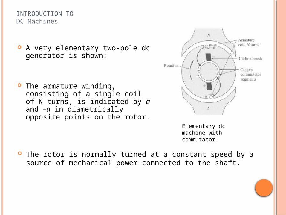
A very elementary two-pole dc generator is shown:
The armature winding, consisting of a single coil of N turns, is indicated by a and –a in diametrically opposite points on the rotor.
INTRODUCTION TODC Machines
The rotor is normally turned at a constant speed by a source of mechanical power connected to the shaft.
Elementary dc machine with commutator.

Although the ultimate purpose is the generation of a direct voltage, the voltage induced in an individual armature coil is an alternating voltage, which must therefore be rectified.
INTRODUCTION TODC Machines
The air-gap flux distribution usually approximates a flat-topped wave, rather than the sine wave found in ac machines, and is shown in figure:
Rotation of the coil generates a coil voltage which is a time function having the same waveform as the spatial flux-density distribution.

The output voltage of an ac machine can be rectified using external semiconductor rectifiers.
This is in contrast to the conventional dc machine in which rectification is produced mechanically by means of a commutator.
INTRODUCTION TODC Machines

In the conventional dc machine the commutator is a cylinder formed of copper segments insulated from each other by mica or some other highly insulating material and mounted on, but insulated from, the rotor shaft.
Stationary carbon brushes held against the commutator surface connect the winding to the external armature terminals. The commutator and brushes can be seen in the figure:
The need for commutation is the reason why the armature windings of dc machines are placed on the rotor.
INTRODUCTION TODC Machines

For the direction of rotation shown in the figure, the commutator at all times connects the coil side, which is under the south pole, to the positive brush and that under the north pole to the negative brush.
INTRODUCTION TODC Machines
For the direction of rotation shown in the figure, the commutator at all times connects the coil side, which is under the south pole, to the positive brush and that under the north pole to the negative brush.
The commutator provides full-wave rectification, transforming the voltage waveform between brushes and making available a unidirectional voltage to the external circuit.

INTRODUCTION TODC Machines
The effect of direct current in the field winding is to create a magnetic flux distribution which is stationary with respect to the stator.
Similarly, the effect of the commutator is such that when direct current flows through the brushes, the armature creates a magnetic flux distribution which is also fixed in space and whose axis, determined by the design of the machine and the position of the brushes, is typically perpendicular to the axis of the field flux.
Thus, just as in the ac machines discussed previously, it is the interaction of these two flux distributions that creates the torque of the dc machine.
If the machine is acting as a generator, this torque opposes rotation.
If it is acting as a motor, the electromechanical torque acts in the direction of the rotation.

MMF OF DISTRIBUTED WINDINGS
INTRODUCTION TO ROTATING MACHINES

Most armatures have distributed windings, which are spread over a number of slots around the air-gap periphery, as in the figures.
The individual coils are interconnected so that the result is a magnetic field having the same number of poles as the field winding.
Stator of a 190-MVA three-phase 12-kV 37-r/min hydroelectric generator .
Armature of a dc motor.

MMF of Distributes Windings
The study of the magnetic fields of distributed windings can be approached by examining the magnetic field produced by a winding consisting of a single N-turn coil which spans 180 electrical degrees, as shown
A coil which spans 180 electrical degrees is known as a full-pitch coil. For simplicity, a concentric cylindrical rotor is shown.
The general nature of the magnetic field produced by the current in the coil is shown by the dashed lines.

MMF of Distributes Windings
Since the permeability of the armature and field iron is much greater than that of air, it is sufficiently accurate here to assume that all the reluctance of the magnetic circuit is in the air gap.
From symmetry of the structure it is evident that the magnetic field intensity Hag in the air gap at angle a under one pole is the same in magnitude as that at angle (a + ) under the opposite pole, but the fields are in the opposite direction.
Around any of the closed paths shown by the flux lines the mmf is N i.
The line integral of H inside the iron is negligibly small, and thus it is reasonable to neglect the mmf drops associated with portions of the magnetic circuit inside the iron.

MMF of Distributes Windings
By symmetry the air-gap fields Hag on opposite sides of the rotor are equal in magnitude but opposite in direction.
It follows that the air-gap mmf should be similarly distributed; since each flux line crosses the air gap twice, the mmf drop across the air gap must be equal to half of the total or Ni/2.
The figure bellow shows the air gap and winding in developed form, i.e., laid out flat.

MMF of Distributes Windings
The air-gap mmf distribution is shown by the steplike distribution of amplitude Ni/2.
On the assumption of narrow slot openings, the mmf jumps abruptly by Ni in crossing from one side to the other of a coil.
This mmf distribution will be discussed again latter.

MMF of Distributes WindingsAC Machines
AC Machines
Fourier analysis can show that the air-gap mmf produced by a single coil such as the full-pitch coil in the figure, consists of a fundamental space-harmonic component as well as a series of higher-order harmonic components.
In the design of ac machines, serious efforts are made to distribute the coils making up the windings so as to minimize the higher-order harmonic components and to produce an air-gap mmf wave which consists predominantly of the space-fundamental sinusoidal component.
It is thus appropriate here to assume that this has been done and to focus our attention on the fundamental component.

MMF of Distributes WindingsAC Machines
The rectangular air-gap mmf wave of the concentrated two-pole, full-pitch coil of can be resolved into a Fourier series comprising a fundamental component and a series of odd harmonics.
The fundamental component Ғag1 is
where a is measured from the magnetic axis of the stator coil, as shown by the dashed sinusoid.
It is a sinusoidal space wave of amplitude
with its peak aligned with the magnetic axis of the coil.
aag
NiF
cos
2
41
2
4)( 1
NiF peakag

MMF of Distributes WindingsAC Machines
Now consider a distributed winding, consisting of coils distributed in several slots.
For example, as in figure bellow that shows phase a of the armature winding of a somewhat simplified two-pole, three-phase ac machine.
Phases b and c occupy the empty slots.
The windings of the three phases are identical and are located with their magnetic axes 120 degrees apart.
Our attention is in phase a alone, postponing the discussion of the effects of all three phases.

MMF of Distributes WindingsAC Machines
The winding is arranged in two layers, each full-pitch coil of Nc turns having one side in the top of a slot and the other coil side in the bottom of a slot a pole pitch away.
In a practical machine, this two-layer arrangement simplifies the geometric problem of getting the end turns of the individual coils past each other.

MMF of Distributes WindingsAC Machines
Figure bellow shows one pole of this winding laid out flat.
With the coils connected in series and hence carrying the same current, the mmf wave is a series of steps each of height 2Ncia (equal to the ampere-turns in the slot), where ia is the winding current.
Its space-fundamental component is shown by the sinusoid.
It can be seen that the distributed winding produces a closer approximation to a sinusoidal mmf wave than the concentrated coil.

MMF of Distributes WindingsAC Machines
The amplitude of the fundamental-space-harmonic-component of the mmf wave of a distributed winding is less than the sum of the fundamental components of the individual coils because the magnetic axes of the individual coils are not aligned with the resultant.
The Fag1 equation is modified for a distributed multipole winding having Nph series turns per phase:
in which the factor 4/ arises from the Fourier-series analysis of the rectangular mmf wave of a concentrated full-pitch coil,
and the winding factor kw takes into account the distribution of the winding.
This factor is required because the mmf's produced by the individual coils of any one phase group have different magnetic axes.
aa
phWag
polesi
poles
NkF
2cos
41

MMF of Distributes WindingsAC Machines
o When they are connected in series to form the phase winding, their phasor sum is then less than their numerical sum.
o For most three-phase windings, kw typically falls in the range of 0.85 to 0.95.
o The factor kw Nph is the effective series turns per phase for the fundamental mmf.
o The peak amplitude of this mmf wave is
aphW
peakag ipoles
NkF
4
)( 1

MMF of Distributes WindingsAC Machines
o Exercise:

MMF of Distributes WindingsAC Machines
o Solution:
Contin.

MMF of Distributes WindingsAC Machines
o Solution (continuation):

MMF of Distributes WindingsDC Machines
• Because of the restrictions imposed by the commutator, the mmf wave of a dc machine armature approximates a sawtooth waveform more nearly than the sine wave of ac machines.
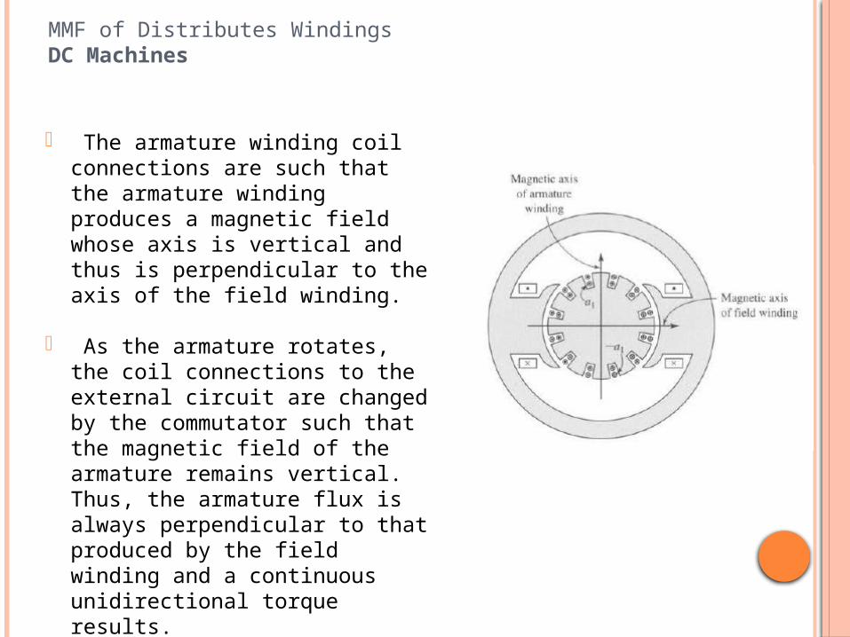
• For example, the figure shows diagrammatically in cross section the armature of a two-pole dc machine. (In practice, in all but the smallest of dc machines, a larger number of coils and slots would probably be used.)
The current directions are shown by dots and crosses.
MMF of Distributes WindingsDC Machines
o The armature winding coil connections are such that the armature winding produces a magnetic field whose axis is vertical and thus is perpendicular to the axis of the field winding.
o As the armature rotates, the coil connections to the external circuit are changed by the commutator such that the magnetic field of the armature remains vertical. Thus, the armature flux is always perpendicular to that produced by the field winding and a continuous unidirectional torque results.

MMF of Distributes WindingsDC Machines
o The first figure shows this winding laid out flat.
o The second, shows the mmf wave.
o On the assumption of narrow slots, it consists of a series of steps.
o The height of each step equals the number of ampere-turns 2Ncic in a slot, where Nc is the number of turns in each coil and ic is the coil current, with a two-layer winding and full-pitch coils being assumed.
o The peak value of the mmf wave is along the magnetic axis of the armature, midway between the field poles. This winding is equivalent to a coil of 12Ncic A.turns distributed around the armature.
o On the assumption of symmetry at each pole, the peak value of the mmf wave at each armature pole is 6Ncic A.turns.

MMF of Distributes WindingsDC Machines
o This mmf wave can be represented by the sawtooth wave drawn in figure.
o For a more realistic winding with a larger number of armature slots per pole, the triangular distribution becomes a close approximation.
o This mmf wave would be produced by a rectangular distribution of current density at the armature surface, as shown.

MMF of Distributes WindingsDC Machines
o It is convenient to resolve the mmf waves into their Fourier series components:
o The fundamental component of the sawtooth mmf wave is shown by the sine wave. Its peak value is:
times the height of the sawtooth wave.
o This fundamental mmf wave is that which would be produced by the fundamental
space-harmonic component of the rectangular current-density distribution. This sinusoidally-distributed current sheet is shown dashed
81.08
2

MMF of Distributes WindingsDC Machines
o Note that the air-gap mmf distribution depends on only the winding arrangement and symmetry of the magnetic structure at each pole.
o The air-gap flux density, however, depends not only on the mmf but also on the magnetic boundary conditions, primarily the length of the air gap, the effect of the slot openings, and the shape of the pole face.
o The designer takes these effects into account by means of detailed analyses.

MMF of Distributes WindingsDC Machines
o DC machines often have a magnetic structure with more than two poles. For example, the figure (a) shows schematically a four-pole dc machine.
o The field winding produces alternate north-south-north-south polarity, and the armature conductors are distributed in four belts of slots carrying currents alternately toward and away from the viewer, as symbolized by the cross-hatched areas.
o This machine is shown in laid-out form in (b). The corresponding sawtooth armature-mmf wave is also shown.

MMF of Distributes WindingsDC Machines
o On the assumption of symmetry of the winding and field poles, each successive pair of poles is like every other pair of poles.
o Magnetic conditions in the air gap can then be determined by examining any pair of
adjacent poles, that is, 360 electrical degrees. The peak value of the sawtooth armature mmf wave can be written in terms of the total number of conductors in the armature slots as:
o whereo Ca = total number of conductors in armature winding
o m = number of parallel paths through armature windingo ia = armature current, A

MMF of Distributes WindingsDC Machines
o This equation takes into account the fact that in some cases the armature may be wound with multiple current paths in parallel.
o For this reason it is often more convenient to think of the armature in terms of the number of conductors (each conductor corresponding to a single current-carrying path within a slot).
o Thus ia/m is the current in each conductor. o This equation comes directly from the line integral around the dotted closed path in
figure (b) which crosses the air gap twice and encloses Ca/poles conductors, each carrying current ia/m in the same direction.

MMF of Distributes WindingsDC Machines
o In more compact form:
o where Na = Ca/(2m) is the number of series armature turns.
o From the Fourier series for the sawtooth mmf wave of fig. (b), the peak value of the space fundamental is given by:

Prof. Elisete Ternes Pereira ,
Nizwa, Spring 2010