coupling as a trade-off in an enterprise service bus · so it is automated by implementing a...
TRANSCRIPT

Coupling as a trade-off in
an Enterprise Service Bus
By
Arie van der Veek
A thesis submitted to the University of Amsterdam
in partial fulfilment of the requirements for the degree of
Master of Science
in
Software Engineering
Thesis supervisor dr. J.J. Vinju
Internship supervisor dr. B. van der Raadt
Amsterdam, The Netherlands 2014

I
Abstract
Traditionally, integration problems between IT systems were solved by point-to-point
connections. These point-to-point connections pose issues with scalability, reliability, and
flexibility. To overcome these issues, companies typically invest in Enterprise Application
Integration (EAI) using an Enterprise Service Bus (ESB) to integrate the IT systems
through a central middleware infrastructure. EAI promises improvement of scalability,
reliability, and flexibility by implementing loosely coupled integration solutions to realise
loosely coupled IT systems.
By wrongly implementing EAI on an ESB IT systems may still be tightly coupled and the
issues with point-to-point connections could be recreated on the ESB. Currently there is
no out-of-the-box solution to identify the integration solution where tight coupling causes
these issues. The goal of this research is to investigate an approach to identify the coupling
state in an Enterprise Service Bus and identify the integration solutions on an ESB which
have a negative impact on the quality attributes due to tight coupling.
The first step in the approach is applying a set of properties on the integration solutions
to identify their coupling state. Manually identifying the coupling state is labour intensive,
so it is automated by implementing a prototype with the Eclipse MoDisco framework. The
second step in the approach is evaluating a trade-off between the risk of being in a certain
coupling state and the efficiency loss of migrating to a less risky coupling state. With the
outcome of the trade-off it can be ascertained whether or not it is beneficial to migrate to
a different coupling state.
The result of the approach is a list of integration solutions for which it would be beneficial
to migrate to a different coupling state. This gives a concrete measure to be able to
determine which integration solutions need to be improved to strive for the optimal
balance between quality and the effort needed to realise quality. The approach was
validated using the ESB implementation of a large European airport as a case study.

II
Acknowledgments
Foremost, I would like to sincerely thank my thesis supervisor, dr. Jurgen Vinju, and my
internship supervisor, dr. Bas van der Raadt. Jurgen’s cheerful attitude and positive
thinking always got me motivated when things looked bleak. Bas helped me greatly with
his ability to trigger a train of thought with the most simple of comments and for
encouraging me when I needed it the most. Without their patience, commitment, and
knowledge, this thesis would never have been possible for which I am eternally grateful.
I would like to express my gratitude to Amsterdam Airport Schiphol, and specifically
Garbis van Okburcht, Rabia Karahan, Eric Lansbergen, and Paul van der Horst for
providing me with the time and resources to be able to do my degree alongside my
fulltime job, and for providing the case study used for this research.
I would like to thank the teaching staff of the Master Software Engineering at the UvA and
CWI for sharing their knowledge and enthusiasm. Specifically, I would like to thank Paul
Klint for an invaluable discussion during the start-up phase of my research, helping me to
forward my initial idea to a concrete research goal.
My sincere thanks also goes to my parents for their support. Throughout my studies
they made sure that in busy times I did not have to worry about the trivial things in life.
Without this, I would not have been able to focus on the work ahead.
Last but not least, my deepest appreciation goes to my girlfriend, Rebecca. Foremost for
putting up with me spending weekends and evenings hidden away behind my computer
working on my studies. Furthermore for proof reading my thesis, even though the subject
made no sense to her at all. I am ever grateful for her love and patience.

III
Table of Contents
Chapter 1. Introduction ........................................................................................................................... 1
1.1 The Enterprise Service Bus ....................................................................................................... 2
1.2 Problem description ..................................................................................................................... 4
1.3 Coupling in an ESB ........................................................................................................................ 4
1.4 Coupling as a trade-off ................................................................................................................ 6
1.5 Theoretical Model ......................................................................................................................... 8
1.6 Metrics ............................................................................................................................................... 9
1.7 The EASY Paradigm, KDM and Modisco ............................................................................. 10
1.8 Research approach ..................................................................................................................... 11
Chapter 2. Identifying coupling state ............................................................................................... 13
2.1 Integration solution definition .............................................................................................. 13
2.2 Properties for identifying coupling state ........................................................................... 14
2.3 Mapping from ESB components to KDM model elements .......................................... 17
2.4 Results .............................................................................................................................................. 18
2.5 Validation ........................................................................................................................................ 20
2.6 Analysis ........................................................................................................................................... 21
Chapter 3. Automating identification of coupling state ........................................................... 22
3.1 The extract phase ........................................................................................................................ 23
3.2 The analysis phase ...................................................................................................................... 26
3.3 The synthesis phase ................................................................................................................... 28
3.4 Results .............................................................................................................................................. 28
3.5 Validation ........................................................................................................................................ 29
3.6 Analysis ........................................................................................................................................... 29
Chapter 4. Ascertaining whether or not decoupling is beneficial ........................................ 30
4.1 Risk assessment ........................................................................................................................... 30
4.2 Calculating efficiency loss ........................................................................................................ 33
4.3 Trade-off between risk and efficiency ................................................................................ 36
4.4 Results .............................................................................................................................................. 36
4.5 Validation ........................................................................................................................................ 37
4.6 Analysis ........................................................................................................................................... 37
Chapter 5. Conclusion and discussion ............................................................................................. 38
5.1 Conclusion ...................................................................................................................................... 38

IV
5.2 Discussion ....................................................................................................................................... 39
5.3 Future work ................................................................................................................................... 42
Bibliography ..................................................................................................................................................... 43
Appendix A Examples of integration solutions ............................................................................ A-1
Appendix B Example application of synchronisation coupling properties ...................... B-1
Appendix C Mapping of integration solution elements to KDM model elements. ......... C-1
Appendix D Example Output Excel file from synthesise phase ............................................ D-1
Appendix E Work executed on Java CAPS ESB ............................................................................. E-1
Appendix F Risk assessment tables .................................................................................................. F-1
Appendix G Efficiency Loss ................................................................................................................... G-1
Appendix H Result evaluation Trade-Off .................................................................................. H-1

1
Chapter 1. Introduction
Many companies have invested heavily in IT in order to support their business processes.
Typically, the IT landscapes of companies have grown in size, diversity, and thus
complexity. This complexity often results in the duplication of functionality and data
across the IT systems, which results in turn in high costs and operational issues keeping
data consistent across these systems. To overcome these challenges, companies invest in
the integration of IT systems. By integrating IT systems it is possible to share functionality
and data across systems, reduce costs, and maintain data consistency. For example,
functionality to support the check-in of a bag for a passenger is implemented in one
central IT system and can be reused in multiple solutions, like a self-service drop off
machine or client application on a manned drop off desk operated by a hostess.
Traditionally this integration problem was solved by point-to-point connections between
the individual IT systems sharing information. In this point-to-point structure, each
individual IT system has a connection with each other system it needs to integrate with,
as shown on the left side of Figure 1. This poses issues with scalability, reliability, and
flexibility [1]. For example, if message definitions between IT systems are tightly coupled,
and a field changes in this definition, then all relevant interfaces need to be changed. The
more interfaces with other IT systems there are, the bigger the ripple effect of the change
to other IT systems. Changing a field becomes quite expensive, and results in less
flexibility of the integration solution.
In the mid 1990's, a new approach to system integration was introduced: Enterprise
Application Integration [2]. Enterprise Application Integration (EAI) is the process of
integrating the IT systems within an enterprise through a central middleware
infrastructure. All IT systems connect via a central middleware platform instead of
connecting directly to each other. This reduces the number of connections needed, which
promises to improve scalability, reliability, and flexibility. If the information needs to be
distributed to a new IT system, this IT system is connected to the central middleware. Via
the middleware, the IT system is connected to all other IT systems.
Figure 1 - Point to Point to EAI (source: www.paw-systems.com)

Chapter 1. Introduction
2
One of the primary goals of EAI is to create loosely coupled IT systems by creating loosely
coupled integration solutions on the EAI platform. This enables IT systems to evolve
separately and the ripple effect of this evolution is minimized for the connected IT
systems [3][p80-81], whereas with point-to-point solutions, the more IT systems
connected to other IT systems, the bigger the ripple effect when integration solutions
change. The goal of EAI is to decouple systems, not components. Components within an
integration solution may be tightly coupled, as long as the integration solution as a whole
is loosely coupled. An integration solution is a set of components that integrates two or
more individual external IT systems via the middleware with the intent to exchange
information between these systems. A more precise definition of an integration solution
will be given in Chapter 2.
1.1 The Enterprise Service Bus
There are many variants of middleware that can be used for EAI. One of the popular
variants today is the Enterprise Service Bus (ESB) [4]. Figure 2 depicts an overview of an
ESB. Different IT systems are connected to the ESB via different protocols, like Java
Message Service (JMS) or Simple Object Access Protocol (SOAP) over HTTP. The core of
an ESB product is a runtime environment, like an application server, in which the
integration solutions are executed, and a message oriented middleware (MOM) platform,
which enables the components in an integration solution to communicate with each other.
So from a runtime perspective, the ESB is an empty container on which integration
solutions can be deployed and executed.
Besides the runtime components, an ESB product consists of a development environment
to create integration solutions. It provides components and frameworks to implement
integration solutions, like specialized protocol adapters, data transformation tools and
message routing components. The ESB does not impose restrictions or enforce a
programming model that ensures loose coupling, which means that by applying an ESB it
is not guaranteed that loosely coupled integration solutions will be realised.
Figure 2 - Overview of an ESB (Source: http://blog.algoworks.com)

Chapter 1. Introduction
3
Figure 3 depicts the relationships between the various ESB components, coupling, and
quality attributes.
Figure 3 – UML model of the relations between the various ESB concepts.
The integration solutions implement the exchange of information between IT systems.
The Enterprise Service Bus is composed of a design time environment to create
integration solutions and a runtime environment to execute integration solutions. The
ESB realises a set of quality attributes, which are either influenced by other sources or by
a coupling type. The other sources that influence quality attributes, besides coupling, are
not within the scope of this research.
1.1.1 The ESB at Amsterdam Airport Schiphol
This research project is conducted at Amsterdam Airport Schiphol. The different IT
systems at Schiphol, which support the operational processes at the airport, need to
exchange information with internal IT systems and the IT systems of sector partners, like
airlines, and air traffic management. The enterprise integration team within the IT
department is responsible for developing, maintaining, and providing support on about
180 integration solutions between these IT systems, of which about half are critical to the
24/7 operational airport processes.
Schiphol, like many companies, adopted an ESB to gain the benefits of a centralized EAI
platform to help solve the challenges of point to point interfacing. By using an ESB they
aim to implement loosely coupled integration solutions to overcome the issues with
scalability, reliability, and flexibility. The ESB product at Schiphol is Java CAPS from the

Chapter 1. Introduction
4
vendor Oracle. Java CAPS is based on Java with additional GUI’s to create integration
solutions configurations, data format mappings, and many other ESB specific tasks. This
thesis will focus on an ESB as EAI platform and use the Schiphol Java CAPS ESB
implementation as a case study.
1.2 Problem description
While the use of an ESB eliminates the external point to point connections, it does not
guarantee the realisation of one of its primary goals. By wrongly applying the ESB, the
point to point connections are shifted to the ESB. This will result in the same tightly
coupled integration solutions as with external point to point integration solutions and
cause the same issues with scalability, reliability, and flexibility. For example, if message
definitions between systems are still shared, the systems are tightly coupled on the ESB
and a change in this message definition still results in a bigger ripple effect of the change
than with loosely coupled systems. Recreating point to point communication on the ESB
may be worse than with explicit point to point connections, because the problems are
hidden away from the IT systems instead of being explicitly present. The IT systems
cannot take measures to mitigate the potential problems because they do not know they
exist.
A challenge for Schiphol is knowing which integration solutions are loosely coupled and
which are in fact point-to-point. Design principles and best practices are applied which
should result in loosely coupled integration solutions, but there is no method in knowing
the coupling state in the ESB based on the actual implementation. Consequently, one of
the major business questions is:
What is the state of the ESB in relation to implementing loosely coupled integration
solutions?
The answer to this questions tells us if the means are in place to achieve the goal of the
ESB, but the question is still too broad. We need to be able to identify the coupling in the
integration solutions and a method to qualify the integration solutions in relation to this
state, so we can express the effect of the integration solution on the goal of the ESB.
1.3 Coupling in an ESB
Coupling stands for the degree to which software components depend on each other
[5][pp. 360]. High coupling means that components highly depend on each other, for
example use the same globally shared data. Low coupling is the opposite where
components depend on each other as little as possible, for example components
communicate though a well-defined interface that hides any logic of the implementation.
The lower the coupling the more loosely a component is coupled.
In general, coupling should be minimized [6]. Services or components should be loosely
coupled to create integration solutions that are less brittle, more flexible, more scalable,
and easier to maintain [7] [pp. 10] [8] [pp. 100]. The properties to qualify as loosely
coupled differ per type of coupling and it differs per type of coupling what goal decoupling
achieves. The types of coupling need to be defined to be able to determine if integration
solutions are loosely coupled or not.

Chapter 1. Introduction
5
1.3.1 Coupling types
The core of an ESB consists of Message oriented Middleware (MoM), which implements a
bus architecture. For a bus architecture Eugster et. al. [9], Aldred et. al. [10] and Walschots
[11] define 3 types of coupling, namely:
• Space coupling: Occurs when interacting IT systems are aware of each other’s
location.
• Synchronization coupling: Occurs when the main thread of control of both the
sending and receiving IT systems cannot continue their execution while an
interaction takes place between them.
• Time coupling: Occurs when IT systems need to participate in an interaction at
the same time.
The definitions by Walschots [11] have been inverted, so they are defined as coupling
instead of decoupling and the word “component” been changed to “IT system”. The types
given are not a complete taxonomy of the types of coupling that can occur between IT
systems. There are many more types, like message/data coupling [6], control coupling [6],
or communication protocol coupling, but for this research these three are enough.
1.3.2 Coupling states
A coupling type has multiple coupling states. Each state can be identified if a set of
properties holds. This enables the identification of the coupling state of an integration
solution. The coupling state can be, for example, coupled, decoupled, or a state in between
depending on the type of coupling. An integration solution can be in one state per coupling
type, but all coupling types can occur in any of the integration solutions. These relations
are depicted in Figure 4.
Figure 4 - UML diagram depicting relations between the various coupling objects
Chapter 1. Introduction
6
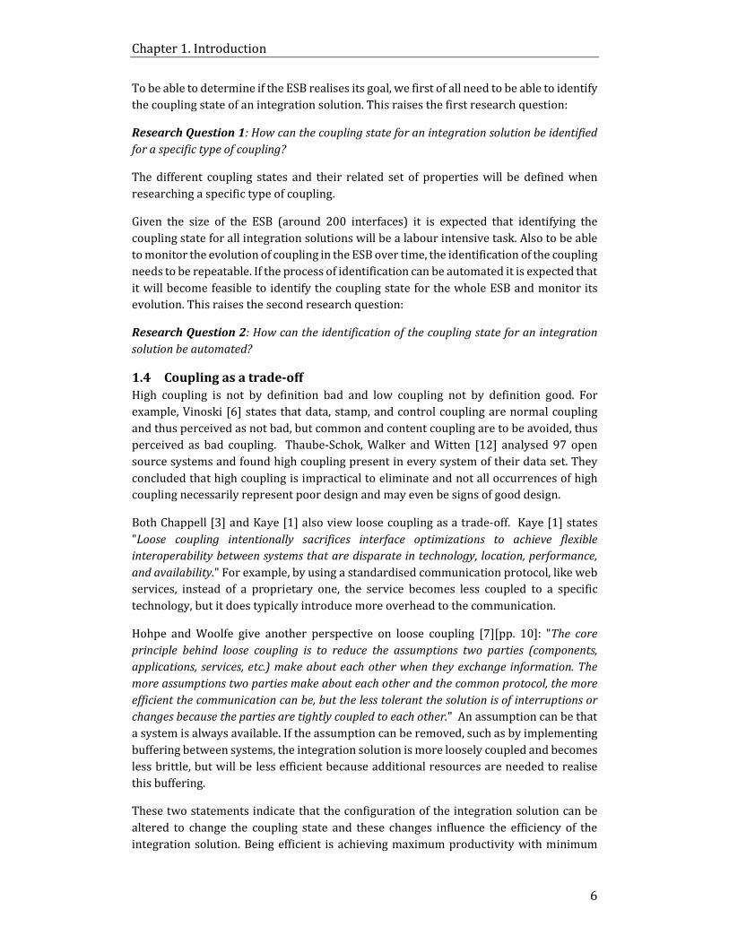
To be able to determine if the ESB realises its goal, we first of all need to be able to identify
the coupling state of an integration solution. This raises the first research question:
Research Question 1: How can the coupling state for an integration solution be identified
for a specific type of coupling?
The different coupling states and their related set of properties will be defined when
researching a specific type of coupling.
Given the size of the ESB (around 200 interfaces) it is expected that identifying the
coupling state for all integration solutions will be a labour intensive task. Also to be able
to monitor the evolution of coupling in the ESB over time, the identification of the coupling
needs to be repeatable. If the process of identification can be automated it is expected that
it will become feasible to identify the coupling state for the whole ESB and monitor its
evolution. This raises the second research question:
Research Question 2: How can the identification of the coupling state for an integration
solution be automated?
1.4 Coupling as a trade-off
High coupling is not by definition bad and low coupling not by definition good. For
example, Vinoski [6] states that data, stamp, and control coupling are normal coupling
and thus perceived as not bad, but common and content coupling are to be avoided, thus
perceived as bad coupling. Thaube-Schok, Walker and Witten [12] analysed 97 open
source systems and found high coupling present in every system of their data set. They
concluded that high coupling is impractical to eliminate and not all occurrences of high
coupling necessarily represent poor design and may even be signs of good design.
Both Chappell [3] and Kaye [1] also view loose coupling as a trade-off. Kaye [1] states
"Loose coupling intentionally sacrifices interface optimizations to achieve flexible
interoperability between systems that are disparate in technology, location, performance,
and availability." For example, by using a standardised communication protocol, like web
services, instead of a proprietary one, the service becomes less coupled to a specific
technology, but it does typically introduce more overhead to the communication.
Hohpe and Woolfe give another perspective on loose coupling [7][pp. 10]: "The core
principle behind loose coupling is to reduce the assumptions two parties (components,
applications, services, etc.) make about each other when they exchange information. The
more assumptions two parties make about each other and the common protocol, the more
efficient the communication can be, but the less tolerant the solution is of interruptions or
changes because the parties are tightly coupled to each other." An assumption can be that
a system is always available. If the assumption can be removed, such as by implementing
buffering between systems, the integration solution is more loosely coupled and becomes
less brittle, but will be less efficient because additional resources are needed to realise
this buffering.
These two statements indicate that the configuration of the integration solution can be
altered to change the coupling state and these changes influence the efficiency of the
integration solution. Being efficient is achieving maximum productivity with minimum

Chapter 1. Introduction
7
wasted effort or expense [13]. In the buffering example, a component is added to decouple
the integration solution, which makes the information exchange less brittle. The added
component requires more work at design time and more resources at runtime, and
therefore is less efficient because it takes more work and resources to exchange the
information. With design time we mean all activities related to designing, building, testing
and deploying integration solutions. With runtime we mean the system resources an
integration solution needs to be executed. So we expect that decoupling an integration
solutions results in some form of efficiency loss, depending on the decoupling method.
Also these two statements indicate that if the integration solution is in a certain coupling
state, the information exchange is exposed to a certain risk. Risk is a situation involving
exposure to danger [13] and is typically expressed as a product of the probability it will
occur and the severity or impact when it occurs [14] [15] [16] [17]. In the buffering
example, by not using buffering between systems, there is a risk of losing messages in case
of interruptions. If the systems are decoupled with a buffer, this risk is eliminated.
Therefore, coupling is best viewed as a trade-off and for this research we view it as the
trade-off between risk and efficiency loss. The identified state for a specific coupling type
poses a certain risk on an integration solution. This risk is specific to the integration
solution, because the severity and probability depends the integration solution and the IT
systems it integrates. Migrating the integration solution to a less risky coupling state may
come at an efficiency loss. With the risk and efficiency loss, we can evaluate the trade-off
and determine the outcome to ascertain if migrating to the different state is favourable.
These relations are depicted in Figure 5.
Figure 5 - UML diagram depicting relations between the various trade-off objects
Even though coupling is a trade-off, the question still remains what state the ESB is in, in
relation to achieving its goal of realising quality attributes like scalability, flexibility, and
reliability. It might be the case that being loosely coupled doesn’t influence achieving the

Chapter 1. Introduction
8
goal of the ESB in such a way that it pays off. The outcome of the trade-off should express
whether or not it is beneficial for the state of the ESB to migrate an integration solution
to a different coupling state. If all integration solutions for which it is beneficial to migrate
to a different state can be identified, we know which integration solutions do not
contribute optimally towards achieving the goal of the ESB and which ones do.
This raises the third research question:
Research Question 3: How can it be ascertained whether or not it is beneficial to migrate
to a different coupling state?
Each type of coupling affects a different set of quality attributes, for example
synchronisation coupling can affect reliability and message coupling flexibility. The set of
quality attributes which are influenced by a coupling type will be defined when
researching that specific coupling type. Defining all quality attributes for an ESB is outside
the scope of this research because the relevant quality attributes depend on the coupling
types.
1.5 Theoretical Model
The discussed theory results in the model depicted in Figure 6 and is used in the
remainder of this thesis. The parts of the integration solutions will be defined in Chapter
2.
Figure 6 – Theoretical model of coupling in an ESB
Chapter 1. Introduction
9
1.6 Metrics
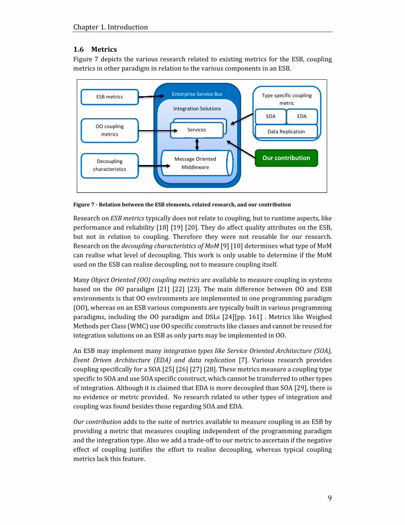
Figure 7 depicts the various research related to existing metrics for the ESB, coupling
metrics in other paradigm in relation to the various components in an ESB.
Figure 7 - Relation between the ESB elements, related research, and our contribution
Research on ESB metrics typically does not relate to coupling, but to runtime aspects, like
performance and reliability [18] [19] [20]. They do affect quality attributes on the ESB,
but not in relation to coupling. Therefore they were not reusable for our research.
Research on the decoupling characteristics of MoM [9] [10] determines what type of MoM
can realise what level of decoupling. This work is only usable to determine if the MoM
used on the ESB can realise decoupling, not to measure coupling itself.
Many Object Oriented (OO) coupling metrics are available to measure coupling in systems
based on the OO paradigm [21] [22] [23]. The main difference between OO and ESB
environments is that OO environments are implemented in one programming paradigm
(OO), whereas on an ESB various components are typically built in various programming
paradigms, including the OO paradigm and DSLs [24][pp. 161] . Metrics like Weighed
Methods per Class (WMC) use OO specific constructs like classes and cannot be reused for
integration solutions on an ESB as only parts may be implemented in OO.
An ESB may implement many integration types like Service Oriented Architecture (SOA),
Event Driven Architecture (EDA) and data replication [7]. Various research provides
coupling specifically for a SOA [25] [26] [27] [28]. These metrics measure a coupling type
specific to SOA and use SOA specific construct, which cannot be transferred to other types
of integration. Although it is claimed that EDA is more decoupled than SOA [29], there is
no evidence or metric provided. No research related to other types of integration and
coupling was found besides those regarding SOA and EDA.
Our contribution adds to the suite of metrics available to measure coupling in an ESB by
providing a metric that measures coupling independent of the programming paradigm
and the integration type. Also we add a trade-off to our metric to ascertain if the negative
effect of coupling justifies the effort to realise decoupling, whereas typical coupling
metrics lack this feature.
Enterprise Service Bus
Integration Solutions
Components
Type specific coupling
metric
SOA EDA
Data Replication OO coupling
metrics
Message Oriented
Middleware
Services
ESB metrics
Our contribution Decoupling
characteristics

Chapter 1. Introduction
10
1.7 The EASY Paradigm, KDM and Modisco
Our approach for analysing the ESB is based on the EASY paradigm [30], which describes
a simple but effective workflow to analyse a System under Investigation (SUI):
• Extract phase: The SUI is parsed and transformed to an internal representation.
• Analyse phase: The facts in the internal representation are analysed and new facts
or models are created to resemble newly gathered insights.
• SYnthesise phase: The internal representation is transformed in results, like code
transformed in another programming language or a report.
In this case SUI is the ESB and all the integration solutions on the ESB. How these phases
are implemented is not defined by the paradigm. Our implementation will be discussed in
the following chapters.
The Knowledge Discovery Meta-Model (KDM) from the Object Management Group (OMG)
is used for the internal representation of the SUI. KDM defines a collection of meta-model
elements whose purpose is to represent existing software artefacts as entities and
relations [31]. For this research we use the following KDM packages:
• The elements from the Platform model in the Resource layer: It contains various
platform elements to model the components of integration solutions and their
relations.
• The elements from the Code and Action models in the Program Elements layer: It
contains various elements to model the source code and interaction between
source code and platform elements.
Not all packages are required, because KDM is aimed to model more aspects of software
than is within the scope of this research.
In order to automate the creation of KDM models for the integration solutions and
identification of the coupling state, we use Modisco. Modisco is a model discovery
framework for Eclipse with support for KDM models [32]. It provides functionality to
implement Discoverer modules which can extract KDM models from a source. It also
contains Query modules to analyse and manipulate the extracted models. While Modisco
provides many features for Eclipse integration and predefined models like KDM, it does
not provide the implementation of the Extraction, Analysis and Synthesis.

Chapter 1. Introduction
11
1.8 Research approach
The research questions already give a global approach and need to be answered in
sequence, each answer providing input for the next question.
1.8.1 Approach for Research Question 1: How can the coupling state for an
integration solution be identified for a specific type of coupling?
To be able to identify the coupling state in an integration solution for a specific type of
coupling, the following steps will be executed:
Step 1: Define the states of coupling for the coupling type and the properties
which should hold for the integration solutions to be associated with a single
defined state.
Step 2: Define a mapping from ESB components to KDM model elements. The
mapping describes the translation from ESB specific components to the internal
representation for integration solutions.
Step 3: Manually execute the Extract, Analyse and Synthesize (EASY) processes to
produce a list of integration solutions and their observed state for a specific
coupling type.
Step 4: Validate the results by inspecting relevant sources on the ESB like log files,
configuration and code.
The result will be models of the integration solutions as well as a list of integration
solutions and their associated coupling state for a specific type of coupling.
1.8.2 Approach for Research Question 2: How can the observation and
identification of the coupling state for an integration solution be automated?
This part of the research mainly consists of creating a prototype that automates the EASY
processes. It reuses the definitions, internal representation and mapping of the previous
question. The result is a prototype that produces the same type of list as in research
question 1, but in an automated manner. The following steps are executed:
Step 1: Choose a source for extracting the facts. There are multiple sources
available containing facts of the integration solutions, like source code.
Step 2: Implement a prototype using Modisco which executes the EASY paradigm
and produces the results in an automated manner.
Step 3: Validate the results produced by the prototype. Results are validated by
inspecting all the produced results and comparing them to the implementation in
the ESB. Since not all variations in integration solutions have been analysed in
research question 1, it is possible that the definitions or processes will need to be
adapted according to the new findings. If needed, steps 2 and 3 are repeated until
the EASY process is implemented correctly.
The resulting prototype should be able to automatically create the integration solutions
models and identify the coupling state for all integration solutions implemented on the
ESB.

Chapter 1. Introduction
12
1.8.3 Approach for Research Question 3: How can it be ascertained whether or not
it is beneficial to migrate to a different coupling state?
To be able to ascertain whether or not it is beneficial to migrate to a different coupling
state, the following steps are executed:
Step 1: Define the variables for the trade-off for the coupling type.
Step 2: Defined the outcomes of the trade-off and the criteria for the outcomes.
Step 3: Evaluate the trade-off for all relevant integration solutions.
Step 4: Validate the results of the trade-off. The validation depend on the defined
variables and outcomes of the trade-off and will be defined after step 3.
Step 5: Analyse if the results of the trade-off can be used to ascertain if migration
to a different state is beneficial. In other words, determine if decoupling an
integration solution pays off in such a way that it improves the goal of the ESB.
The result is a list of integration solutions with the outcome of the trade-off. With this list
we expect to be able to determine if they contribute to achieving the goal of the ESB and
whether or not migration is beneficial.
It is expected that this approach is usable for all types of coupling found on an ESB, but
we will start with synchronisation coupling. Synchronisation coupling is, from a Schiphol
perspective, the most interesting type of coupling, because it can result in runtime halting
of IT systems. This is not desired for the mission critical environment in which Schiphol
deploys its ESB.
The remainder of the thesis is organised as follows: Chapter 2 covers research question
1, manually identifying the state of synchronisation coupling for an integration solution.
Automating the identification process for research question 2 is discussed in Chapter 3.
Research question 3, ascertaining if migrating to a different coupling state is favourable,
is covered in Chapter 4. Finally in Chapter 5 conclusions are given and it is discussed
whether the results of the research answer the business question raised in the
introduction.

13
Chapter 2. Identifying coupling state
To identify the coupling state for synchronisation coupling in an integration solution the
following needs to be defined:
• The coupling states for synchronisation coupling.
• The integration solution.
• The properties to identify coupling state in an integration solution.
• The mapping between the ESB components and KDM internal representation.
With these definitions we can manually execute the EASY paradigm to identify the
coupling state in an integration solution and do the initial verification of our approach.
As stated before, synchronization coupling occurs when the main thread of control of both
the sending and receiving IT systems cannot continue their execution whilst an
interaction takes place between them. The coupling state for synchronisation coupling is
either coupled or decoupled [10], also known as synchronous or asynchronous. There is
no gradation between coupled and decoupled.
2.1 Integration solution definition
Figure 8 depicts the UML model for an integration solution and its subparts. The
remainder of the paragraph describes the elements of the model and the properties
defining an integration solution. Using the properties, the models of the integration
solutions can be extracted from the ESB, so their coupling state can be identified.
Figure 8 - UML model for an integration solution and its parts
Resource [31][pp 178]: A resource resembles a facility provided to the application by the
platform it runs on. Examples are: JMS queues or topics, TCP/IP sockets, databases or file
systems.
External System: IT System outside the ESB platform. We view an external system
relative to the ESB as a specialized type of resource, so an external system is a resource
not located on the ESB. For example the Oracle EBS ERP application is an external system,
which is exposed as both a JMS resource and a database resource.

Chapter 2. Identifying coupling state
14
Internal destination: A destination is a queue or topic deployed on the Message Oriented
Middleware (MoM) component within the ESB. It is mainly used to realise asynchronous
communication as it acts as a buffer between systems. It is a specialized type of resource.
A queue or topic can be used to expose an external system. In that case they are an
external system and not an internal destination.
Service: A software component which performs a programmed task that involves at least
reading and/or writing from resources. It can also be translating a message, routing a
message, etc. Service is also a specialisation of a resource. They have no relation to the
notion of services in SOA, other than that they could be used to compose SOA services.
Service Implementation: A set of computer instructions which realise the desired
behaviour of the service. A service implementation can be used by multiple services, for
example for generic behaviour to retrieve a file from an SFTP server.
Integration solution: A solution to integrate two or more individual external systems via
the ESB with the intent to exchange information between these systems. An integration
solution is always directional. The integration solution is initiated from one external
system and then reads and writes from one or more external system. If bidirectional
communication is needed, there are two separate integration solutions.
More formally, we define an integration solution as an aggregation of resources with
relations that form a directed graph for which the following properties hold:
1. There is a relation between a service and a resource, so that all nodes are
connected. So it should be a weakly connected graph.
2. If the resource is an external system, there is only a relation between the
external system and exactly one service in the integration solution. Otherwise
two separate integration solutions would become one.
3. For at least one external system the following property should hold: From the
external system there should be a path to at least one other external system. This
property makes sure there is an information flow from a system to another
system.
4. There may only be one relation from a unique topic to a unique service. A topic
implements a 1 to N relationship. If the N is a path to an external system it is a
unique integration solution.
Appendix A contains examples of integration solutions to clarify the definitions and the
properties which define an integration solution.
There might also be cases where systems communicate directly to each other through a
messaging resource on the ESB. In this case the ESB only provides a messaging resource
for the systems and we do not consider it an integration solution on the ESB, because no
software has been built on the ESB. Therefore it is not relevant for this research.
2.2 Properties for identifying coupling state
The properties which identify a coupling state in the integration solution depend on
various aspects, like the presence of a decoupling mechanism, the type of transactions
used, and whether or not the protocols used are inherently synchronous. These will be
explained in the following paragraphs, and finally the properties to identify the coupling
state will be defined.

Chapter 2. Identifying coupling state
15
2.2.1 Decoupling communication using messaging
Messaging should be used to integrate systems in an asynchronous fashion, as opposed
to, for example, Remote Procedure Calls (RPC) that are considered synchronous [7] [3].
With messaging, services do not communicate directly with each other, but via Message
Oriented Middleware (MOM). This realises decoupling of the services, because they can
deliver the message to the MOM and continue their work. The service does not have to
wait until the other service is done with its work. By decoupling the services with MOM,
the integrated IT systems are also decoupled. The ESB implementation under
investigation provides MoM based on the Java Messaging Service (JMS) specification and
is classified as asynchronous.
Eugster et al. [9] explain that Tuples, CORBA and Java Spaces, for example, can also act as
decoupling mechanisms. We assume MoM is the only way that decoupling is implemented
on an ESB. This assumption is valid for this case study and expected to be valid for all
major Java based ESB implementations. This assumption helps us limit the number of
decoupling mechanisms which should be detected during the observation. If this
assumption is invalidated, the observation process needs to be changed to detect other
decoupling mechanism.
If the path from one external system to other external systems is followed in an
integration solution and one of the resources in this path is a destination deployed on the
MoM, then the integration solution is asynchronous. If not, it might be synchronous. There
is another factor that influences the locking of resources, namely transactions.
2.2.2 The influence of transactions
If an integration solution contains only one service or multiple services which call each
other, then the type of transaction the services have with the external systems influence
if the integration solution integrates the systems synchronous or asynchronous. If a
service starts a transaction and locks resources on a system, the system cannot use the
resources while the transaction takes place. If a service opens multiple resources on
multiple systems, then the systems in the transaction need to wait until the work is
finished or the resource to become available again. An integration solution is then
synchronous, because the thread of control in a system cannot continue while the
interaction between systems takes place.
Within an ESB we can distinguish two types of transactions, namely eXtended
Architecture (XA, also known as global transactions) and non XA transactions. The main
difference between XA and non XA in relation to synchronisation coupling is that with XA
the transaction always locks all resources simultaneously during the transaction, while
with non XA transactions it depends on the implementation of the service. That is to say,
with XA we know for sure the thread of control cannot use the resource whilst the
interaction takes place. With non XA, this depends if the implementation opens multiple
resources simultaneously. If a service in an integration solution reads or writes multiple
resources and uses an XA transaction, the service is synchronous. Non XA transactions
can be either synchronous or asynchronous. Should there be no transactions, the service
is asynchronous. The size of a transaction does not influence the coupling state because
there is no gradation in synchronisation coupling. However, the risk may be higher that
the systems could halt, as the probability of failure is increased with larger transactions.

Chapter 2. Identifying coupling state
16
2.2.3 ESB as synchronous server
Integration solutions can expose their functionality on the ESB or call an external system
using protocols which are synchronous, like HTTP1. For example, with HTTP when the
client has sends a request to the server, it needs to wait for the reply from the server
before it can continue its work. The reply is only sent to the client when the service that
has been invoked has finished all its work. This behaviour is very similar to a transaction,
due the fact that the invoking external system is locked until the reply is given.
When the ESB uses a synchronous protocol, whether or not it integrates the IT systems
synchronously depends on the integration solution implementation. Figure 9 depict two
integration solutions using the HTTP protocol service to expose their functionality. The
first integration solution integrates the two systems asynchronously, because there is an
internal destination in between them. The HTTP protocol based service can finish its work
by publishing the message on the internal destination. The reply message can be sent
when the message is published and no other external system is locked. In the second
integration solution there is no decoupling mechanism. The reply to the client can only be
given when the work with the other external system is finished which locks the invoking
external system. Therefore the defined properties need to take into account the ESB
acting as a synchronous server and the configuration of the integration solution in
identifying the coupling state as synchronous or asynchronous.
Figure 9 - asynchronous and synchronous integration solution with an HTTP server
2.2.4 Definition of properties
An integration solution is asynchronous when none of the external systems’ interacting
resources are locked at the same time, so external systems can continue their work while
an information exchange between the systems takes place. The following property
determines the synchronisation coupling state of an integration solution:
1 HTTP is built on top of the TCP/IP protocol which has asynchronous properties, but effectively
HTTP itself is synchronous due to the specification of a mandatory request/reply pattern in the
protocol.
External
Systems ESB platform
Mapping
and Filter
Oracle
database
FromXtoY
HTTP
Server
External
Systems
MySQL
database
Oracle
database HTTP
Server MySQL
database Mapping
and Filter

Chapter 2. Identifying coupling state
17
Property for determining the coupling state for synchronisation coupling
Let the integration solution be a non-directed graph.
An integration solution is in the asynchronous state if for all external systems in an
integration solution the following property holds:
For all paths from the external system to all other external systems one of the
following properties holds:
1. One of the external systems is exposed via a decoupling mechanism, for
example in our ESB case study a messaging resource like a queue or a topic.
2. There is a decoupling mechanism in the path of the external systems, for
example in our ESB case study an internal destination like a queue or a topic.
3. For all services in the path between the external systems, the relations of these
services with other external systems or services may not lock multiple
resources at one time. Locking multiple resources occurs when:
a. The relation is XA transactional or a synchronous server.
b. The relation is transactional and other transactions are open at the same
time as the transaction. In other words, only one transaction can be open
at any one time in a service.
Otherwise the integration solution is in the synchronous state.
These properties take into account the decoupling mechanism, the XA and non XA
transactions and the ESB as synchronous server. They also take into account cases where
there are multiple paths from one external system to another in an integration solution.
If one of these paths is synchronous, the two external systems are coupled synchronous,
regardless of other paths. An example of the application of properties is provided in
Appendix B.
2.3 Mapping from ESB components to KDM model elements
To be able to manually (or automatically) extract the models from the source code
repository, the elements of the source code repository need to be mapped to KDM model.
The KDM models need to contain enough fact to be able to apply the properties to the
model, for example the type of relationship between KDM model elements or
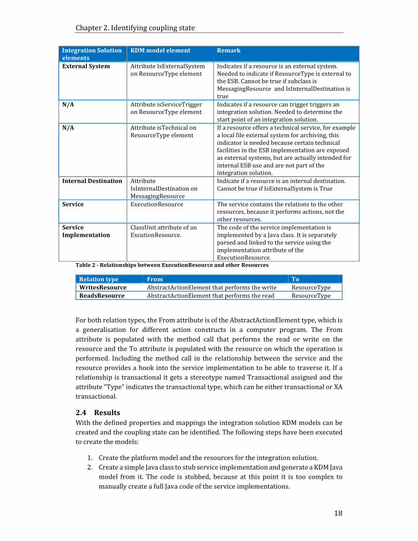
transactionality type of this relation. Table 1 describes the relations between the
elements, Table 2 describes the relation types between resources.
Table 1 - Mapping from integration solution elements to KDM model elements
Integration Solution
elements
KDM model element Remark
Integration Solution PlatformModel A model containing a set of ResourceTypes
Resource ResourceType
The specialisations of the resources for each type
of system are defined in Appendix A. Example: a
queue or topic is a MessagingResource and a
database is a DataManager.
Chapter 2. Identifying coupling state
18
Integration Solution
elements
KDM model element Remark
External System Attribute IsExternalSystem
on ResourceType element
Indicates if a resource is an external system.
Needed to indicate if ResourceType is external to
the ESB. Cannot be true if subclass is
MessagingResource and IsInternalDestination is
true
N/A Attribute isServiceTrigger
on ResourceType element
Indicates if a resource can trigger triggers an
integration solution. Needed to determine the
start point of an integration solution.
N/A Attribute isTechnical on
ResourceType element
If a resource offers a technical service, for example
a local file external system for archiving, this
indicator is needed because certain technical
facilities in the ESB implementation are exposed
as external systems, but are actually intended for
internal ESB use and are not part of the
integration solution.
Internal Destination Attribute
IsInternalDestination on
MessagingResource
Indicate if a resource is an internal destination.
Cannot be true if IsExternalSystem is True
Service ExecutionResource The service contains the relations to the other
resources, because it performs actions, not the
other resources.
Service
Implementation
ClassUnit attribute of an
ExcutionResource.
The code of the service implementation is
implemented by a Java class. It is separately
parsed and linked to the service using the
implementation attribute of the
ExecutionResource. Table 2 - Relationships between ExecutionResource and other Resources
Relation type From To
WritesResource AbstractActionElement that performs the write ResourceType
ReadsResource AbstractActionElement that performs the read ResourceType
For both relation types, the From attribute is of the AbstractActionElement type, which is
a generalisation for different action constructs in a computer program. The From
attribute is populated with the method call that performs the read or write on the
resource and the To attribute is populated with the resource on which the operation is
performed. Including the method call in the relationship between the service and the
resource provides a hook into the service implementation to be able to traverse it. If a
relationship is transactional it gets a stereotype named Transactional assigned and the
attribute “Type” indicates the transactional type, which can be either transactional or XA
transactional.
2.4 Results
With the defined properties and mappings the integration solution KDM models can be
created and the coupling state can be identified. The following steps have been executed
to create the models:
1. Create the platform model and the resources for the integration solution.
2. Create a simple Java class to stub service implementation and generate a KDM Java
model from it. The code is stubbed, because at this point it is too complex to
manually create a full Java code of the service implementations.

Chapter 2. Identifying coupling state
19
3. Add the KDM Java model to the Execution Resources as the implementation.
4. Create the relationships between the ExecutionResources and the other
PlatformResources. Depending on the action performed on the resource in the
service implementation a ReadResource and/or WriteResource relationship is
created.
5. Set the attributes in the resources and the stereotypes for the relationships if
applicable.
The following models were created based on the implementation in the ESB case study
using the GUI of Modisco:
1. An asynchronous integration solution pushing flights from Central Information
System Schiphol (CISS) to a ground radar application. (First integration solution
of Figure 17 in Appendix A)
2. A synchronous integrating solution reading data from one database (RCS) and
inserting it into another database (Maximo). (First integration solution of Figure
16 in Appendix A)
A screenshot of the resulting models in the KDM GUI is depicted in Figure 10.
Figure 10 - Segment with manually created integration solutions
2.
3.
1.
4.

Chapter 2. Identifying coupling state
20
Next the properties for determining if an integration solution is synchronous or
asynchronous were manually applied to identify the coupling state.
Model 1 is asynchronous, because there is one path, namely external system
FromCISSQueue to the ground radar web service external system for which all properties
hold. Property 1 holds, because CISS is a Messaging Resource and the attribute “external
system” is true. Property 2 holds, because in the path between the FromCISSQueue and
the ground radar web service there is MessagingResource called FromCISSTopic, which
is a decoupling mechanism. Finally property 3 holds, because the services in the path from
the FromCISSQueue to the ground radar web service does not contain any relations that
cause a lock on multiple external systems simultaneously. While it is enough for only one
of these properties to hold to qualify an integration solution as asynchronous, in this case
all properties hold.
Model 2 is synchronous because none of the properties hold for the single path between
the RCS and Maximo external systems. Neither RCS nor Maximo is deployed on a
messaging resource, so property 1 does not hold. In the path from RCS to Maximo there is
no decoupling mechanism, the service communicates directly with the systems, therefore
property 2 does not hold. Both the relationship with RCS and Maximo is non XA
transacted and in the services both transactions are open simultaneously, so property 3
does not hold. The source code of the service implementation has been inspected to
ascertain this fact, because the Java model is based on a stub.
2.5 Validation
There are multiple integration solutions reading a flight message and sending it to
external systems depicted in Figure 17 with the same setup as model 1. The behaviour we
see on the production environment is that the other services continue their work and the
messages for that halting system are buffered when there is an incident where one of the
external systems halts. CISS is able to produce messages and the ESB is able send them to
all external systems, except the halting one. This is due to the topic and queues in the
integration solution which realise decoupling. So when one external system halts it does
not cause the other external systems to also halt, because they are asynchronously
integrated. This observed runtime behaviour, combined with the source code and
configuration, confirms that the external systems are integrated asynchronously, because
halting of one system does not cause halting of other systems participating in the message
exchange.
For model 2 there were no log files or running integration solutions available because the
interface has been replaced on production by an asynchronous version. The validation is
executed using the source code and configuration in the ESB repository. The configuration
shows there is only one service in the integration solution and no decoupling mechanism.
The code of the service implementation shows that the auto commit feature of both the
RCS and the Maximo database connector is set to false before any actions are done on both
systems and the commit is manually executed when all actions are finished. This means
multiple transactions are open at the same time, locking the two external systems
simultaneously. If one of the external systems halts, the lock is not released on the other
resource, because the commit on the transaction is never reached. The implementation
shows that this integration solution is asynchronous.

Chapter 2. Identifying coupling state
21
2.6 Analysis
We are able to manually create models of integration solutions given the definitions and
the defined mapping between the definitions and KDM model elements. Using the
properties for determining synchronisation coupling state and the KDM model, we are
able to identify the coupling state of a limited set of integration solutions. The manual
creation of the models indicates that the defined properties should be usable for creating
a list of integration solutions and their associated coupling state.
It was expected that identifying the coupling state of all integration solutions would be a
labour intensive task. This expectation is true, because creating the two models turned
out to be about a working day to create by hand. With the estimate of roughly 200
integration solutions on the ESB, it would take about 100 days to create all the models.
This is excluding performing the identification of synchronisation coupling manually.
Automation is necessary to make the approach feasible for a large set of integration
solutions. Also a larger set of integration solutions provides a larger set to validate the
properties.
Modisco is able to generate Java code models of the service implementations. The Java
code model captures, among other facts, all the method invocations in the code, but there
is no relation between the method invocations and the object on which the method
invocation is performed. For the manual creation of the model this is not an issue, as the
researcher can inspect the code and configuration for which object the method invocation
is performed. The lack of relation between object and method invocation will pose an
issue for automating the model creation and analysis because without this relation we
cannot ascertain what method invocation is performed on what object. This means it
cannot be ascertained what actions are performed on a resource, and therefore we cannot
create the relations or gather other facts base on the implementation. An alternative
solution needs to be implemented for automation.
The next chapter will discuss how the KDM models for the integration solutions can be
extracted from the repository and their coupling state be identified automatically using a
Modisco Discoverer.

22
Chapter 3.
Automating identification of coupling state
The automation of the EASY paradigm is implemented by an Eclipse Modisco Plugin
implementation called Integration Solution Coupling Analysis Tool (ISCAT). It contains a
Modisco discoverer, a set of queries to analyse and transform the models, and an Excel
export function to export the result. Figure 11 depicts the automated implementation of
the EASY paradigm at a high level. This chapter explains the functionality of the
components built to implement the EASY paradigm and the results of the automation.
Figure 11 – The EASY paradigm implementation by ISCAT
The source for automatically creating the integration solution models is the source code
repository of the ESB. The source code repository contains both the configurations which
define the resources and relations of the integration solutions, and the source code of the
service implementations. The compiled code is not an option because it also contains all
the code generated by the ESB framework, which severely obfuscated the analysis with
code which is not relevant. Log files are not an option because not all parts of the
integration solutions log information on the ESB and are therefore not reliable.
Documentation is not an option because it only contains drawings and written
specifications, which cannot be automatically parsed and may be incomplete.
Modisco Discoverer module
<<SUI>>
Java CAPS Repository
<<Extract>>
Java CAPS Parser
<<Internal Representation>>
Integration Solution
KDM Models
<<Analyse>>
Multiple Modisco
Queries
<<Synthesize>>
Excel export for list
generation
<<Result>>
List with all integration solutions and
their coupling state
Multiple Queries are chained
each transforming the model
Code Configuration
Chapter 3. Automating identification of coupling state
23
3.1 The extract phase
The extract phase is implemented by the Java CAPS Parser. The following steps are
executed by the parser:
1. The repository tree is traversed and keeps track of all the relevant Java CAPS ESB
components.
2. All the external systems and internal destinations found in the tree traversal are
put into the model, each type in their own sub model.
3. The services are created by parsing all the Java CAPS connection maps2. For each
service the relations are extracted as well as what resources they read or write
from. The relations are retrieved from the connection map and the direction of
each relation is determined by analysing the service implementation.
The output of the parser is three platform models which contain the external systems,
internal destinations and the services with the relations to the other resources. These
models do not contain integration solutions yet. They are created in the analysis phase.
3.1.1 Direction of relations
The major challenge for the extract phase was determining the direction of a relation, in
other words if the service reads the resources, writes them, or performs both actions. This
is required to make the resulting graph of an integration solution directional. Figure 12
depicts a Java CAPS connection map with a service, its relations to the platform resources,
and a simplification of the corresponding service implementation. The relations of the
service are directional, but their direction does not correspond to a read or write action.
The service implementation needs to be parsed to determine the actual direction. For
example, the relation from the service to an Oracle Database external system in Java CAPS
is from the service to the external system. The service implementation on the other hand
shows that a read is performed on an Oracle database external system, represented by
the executeQuery() method invocation. So the direction of the relationship in the
connection map does not provide the actual direction of the relationship and the code
must be parsed to determine if it is a ReadResource or WriteResource relationship.
2 A connection map is a Java CAPS specific configuration concept, which contains all the
relationships between the services and the resources and the configuration of these relationships.

Chapter 3. Automating identification of coupling state
24
Figure 12 - Java CAPS Service with its relations
To determine the direction of the relationship and its properties, the following steps are
executed:
1. Get the relations for the service. The relation is linked with the service by a port,
essentially this is an object passed in the receive() method call
2. The code is analysed using the object from the port to ascertain what action is
performed on the resource. This can be either a read, write or both.
3. Now the ReadResource and/or WriteResource relations can be made, where the
From AbstractActionElement is the method which executes the read or write
operation. For the otdOraEDMS object it is the ExecuteQuery() method invocation.
For the jmsOut object it is the send() method invocation. To determine if a method
invocation reads or writes, it is matched to a predefined list of operations and
their association to a read or write.
Simplified Service Implementation of svcFromEDMSDocLink
public void receive(
com.stc.connectors.jms.Message input,
com.stc.connectors.jms.JMS jmsOut,
nl.schiphol.asb.messages.ASBMessage otdAsbMessage,
otdOraEDMS_MaximoObjects.OtdOraEDMS_MaximoObjectsOTD otdOraEDMS_MaximoObjects,
nl.schiphol.asb.maximo.messages.edmsdoclink.edmsdoclink.EDMSDocLink_
otdEDMSDocLink )
throws Throwable
{
// First read all the MaximoOjects records in EDMS.
otdOraEDMS_MaximoObjects.getPsSelectMaximoObjects().executeQuery();
If(otdOraEDMS_MaximoObjects.getPsSelectMaximoObjects().resultsAvailable()){
// ....
// Creat the message
com.stc.connectors.jms.Message jmsMessage = jmsOut.createTextMessage(
messageOut );
// Send the message
jmsOut.send( jmsMessage );
} else {
loggerProvider.getDefaultLogger().error( "No records found." );
}
}
Read from external system
Write to external system
Configuration
Node
List of ports

Chapter 3. Automating identification of coupling state
25
4. To add the required stereotypes to the relations, like the transaction type, the
configuration node of the link is parsed.
As stated in paragraph 2.6 the KDM code model does not contain the relations between
the method invocation and the object. It is known that the object relates to the external
by the relationship between the service, and for the method invocations is know if they
read or write. Without the relation between object and method invocation it cannot be
determined on what relations a read or write is performed. Therefore step 3 cannot be
executed and an alternative approach needs to be implemented.
The KDM Java model in Modisco is based on the Java Development Tool (JDT)
specification and related Eclipse implementation. The JDT Java model offers the correct
amount of detail to analyse the Java code to determine the relationships. The issue with
using the JTD Java model is that it is not a KDM compatible model. The from attribute in
the ReadResource and WriteResource (see Table 2) needs to be of KDM type
AbstractActionElement, and the ExecutionResource implementation attribute needs to be
of KDM Type AbstractCodeElement. Both KDM types are not know in the JDT Java model,
so it is not easily possible bridge to the JTD model from the KDM model. Therefore this
alternative is not viable for this research.
The chosen solution is to parse the Java code as text and determine the direction of the
relationship by validating the code against a set of regular expressions. Regular
expressions are defined for all the read and write method invocations for a specific type
of resource. With these regular expressions it can be ascertained if it relationship is a read
or a write.
Using regular expressions instead of the Java model does pose potential issues:
• The operation which indicates read or write needs to be related to the object
which resembles the resource. Just searching for the operation, without the
context of the object might link the operation to a different resource leading to the
wrong direction being concluded. This has been solved for this case by making the
regular expression dynamic so it searches for the operations related to the object
resembling the resource.
• Passing of the object between classes cannot be followed easily if multiple classes
are used by the service implementation. If read or write actions are done in a
different class, this might not be detected. For this ESB implementation this is not
an issue because each service is implemented by a single class and no other classes
are called. This is a built in limitation of the Java CAPS ESB framework.
• The name of the object in the signature of a method within the class implementing
the service is different. For example, object X defines a resource and it is passed
to a separate method which executes the read where the object is called Y. The
regular expression will not find the read because it is looking for an object called
X instead of Y. In this case study, the development standards make sure that the
same name for the object is used in the entire code, therefore it should always be
possible to follow an object in different methods. During the execution some
exceptions were found and for each exception a specific regular expression was
defined to identify that unique case, which solves this issue.

Chapter 3. Automating identification of coupling state
26
Given the limited time for this research, using regular expressions was viewed as the most
viable option. Creating a bridge between KDM and JDT would consume a lot more time
than implementing the regular expression. The issues with regular expressions for this
type of coupling can be fixed for the ESB in this case study, but for other case studies, and
potentially other types of coupling, the decision needs to be revisited.
Because there is no AbstractActionElement in the implementation to reference to in the
From attribute of the ReadResource and WriteResouce, both relation types cannot be
used anymore. The more generic PlatformRelationship is used to express the relation
between the ExecutionResource and other resources. If the relationship is from the
resources to the ExecutionResource, it represents a read action. If the relationship is From
the ExecutionResource to the other resources, it represents a write action.
3.2 The analysis phase
To implement the analysis phase a set of Modisco queries is programmatically executed
on the model, each query transforming the model until the desired results are produced.
The following queries are executed in the given sequence:
1. AddNonESBIS: Adds the resources and their relation to the model for the web
service integration solutions built outside the ESB framework (See Appendix B)
2. CreateInterfaceModels: Creates interface models from the three models produced
by the Java CAPS parser using a specialised algorithm (see 3.2.1). Each interface
model is a directed graph, just like an integration solution, but not yet pruned of
technical external systems or validated against the integration solution
properties.
3. RemoveTechnicalExternalSystems: Removes all resources marked as technical,
like the Batch Record Parser, so only “real” external systems are left in the
interface models. Leaving the technical external systems in the integration
solutions would potentially result in paths which are not actually representing an
information flow from one external system to another.
4. SeparateAllModelsNotValidAgainstISProperties: Separates all the models which
do not validate again the properties defining an integration solution (paragraph
2.1) and puts them in a separate model segment. These models are not of interest
for this research as they are not integration solutions, but technical interfaces.
5. SeparateAllASyncIS: This query separates all the models for which the properties
for the asynchronous coupling state do not hold as specified in paragraph 2.2 and
puts them in a separate model segment. Due to the issues with the Java Model,
property 3b could not be fully checked, which is explained in 3.2.2. The result of
this query is a model segment with asynchronous, thus decoupled, integration
solutions and a model segment with synchronous, thus coupled, integration
solutions.

Chapter 3. Automating identification of coupling state
27
After executing the final query the resulting model is finished. It contains a set of KDM
models for synchronous integration solutions, asynchronous integration solutions, the
technical interfaces, and the original resources from the repository
3.2.1 Algorithm to produce interface models
The algorithm to create the interface models is similar to an algorithm to traverse a graph.
The algorithm takes an external system and for all the services that read from the external
system it traverses the tree using a depth-first approach. Each encountered vertex is
added to the model. Unlike to a normal graph traversal algorithm, our algorithm stops
traversing a path in the tree when it encounters an external system as a vertex instead of
traversing until there are no more vertices available. This way the graph complies with
property 2 of an integration solution: “There can only be a relationship between an external
system and exactly one service in an integration solution”.
Property 4 of an integration solution states that there may only be one relation from a
unique topic to a service in an integration solution. Each time the algorithm finds a topic
in the path with more than one service read from it, the model up to and including the
topic is copied for each reading service. The copied models are then traversed, each
resulting in a separate integration solution.
It is possible for an integration solution to have cycles. If the algorithm did not stop
traversing the cycle, it would continue traversing indefinitely. To avoid this issue the
algorithm checks for cycles by ascertaining if the service has not already been visited. If
the service has been visited, the algorithm stops following that path and continues with
other paths if required.
3.2.2 Changes to determining transaction type of relations
The Java code needs to be analysed to be able to check for property 3b for identifying the
coupling state: “The relation is transactional and other transactions are open at the same
time as the transaction”. The lack of Java models of the service implementations prohibits
the execution of this check. The alternative of analysing the code with regular expressions
to determine the direction of relations is not viable, as it is expected that this would
become too complex and too time consuming to implement for this problem. The applied
workaround is simplifying property 3 a and b to:
The relation is XA transactional, transactional or a synchronous server
This implies that if non XA are used, it is assumed that the transactions occur
simultaneously. Implementing this simplified version of this property may result in false
positives. Integration solutions which use non XA transactions and do not have
simultaneous transactions will be falsely marked as synchronous. We expect the number
of false positives to be minimal or non-existent because the ESB implementation under
investigation tends to favour XA transactions over non XA transactions. Additionally
where non XA transactions are used, the transactions are typically open simultaneously.
During the validation of the results, the synchronous integration solution using non XA
transactions will be explicitly checked to identify false positives.

Chapter 3. Automating identification of coupling state
28
3.3 The synthesis phase
During the synthesis phase, the results are exported by an export module, which creates
a report summarising the results of the model. The report is stored in a Microsoft Excel
file created with the Apache POI framework3. The results contain the following:
a. An overview of the number of synchronous integration solutions, asynchronous
integration solutions and technical interfaces.
b. A list of all integration solutions with their associated coupling state.
c. A list of technical interfaces.
Appendix D includes an example of the Excel output. Excel allows for easy manipulation
of data and further analysis. If extra result output is desired from the synthesis phase, it
can be programmatically added to the export module.
3.4 Results
With the ISCAT discoverer it is now possible create integration solution models by
extracting the required information from the Java CAPS repository. With these models the
coupling state of an integration solution in relation to synchronisation coupling can be
identified. Running the discoverer on Schiphol ESB Java CAPS repository produces the
following results:
Asynchronous integration solutions: 159
Synchronous Integration solutions: 17
Technical Interfaces: 16
Figure 13 depicts an overview of the resulting KDM models. From these models we can
synthesize the resulting lists.
Figure 13 - Overview of KDM Models after the analysis phase
3 Site: http://poi.apache.org/

Chapter 3. Automating identification of coupling state
29
3.5 Validation
First we validated if all integration solutions were transformed to models, and they were
complete and correct by manually checking the output of the discoverer against the
implementations in the Java CAPS repository. Some issues could not be fixed in the
discoverer and required a change in the repository. These were mainly issues with
duplicate integration solutions as a result of unfinished refactoring activities. This
resulted in the same integration solution being in the list multiple times, which would
influence the result by counting the wrong number of integration solutions. The applied
repository fixed are listed in Appendix E. After fixing these issues, all produced models
are correct and complete, and all integration solutions have been transformed to models.
Next we validated if coupling state was correctly identified by manually inspecting the
code and configurations. All the synchronous integrations have been inspected to validate
that they are not falsely identified as synchronous. Besides checking if the properties were
applied correctly, this involved validating that there were no false positives as a result of
changing the non XA transaction property as described in 3.2.2. For the synchronous
integration solutions which used non XA transactions, the code showed that the
transactions were open simultaneously. For all synchronous integration solutions the
properties were applied correctly and no false positives were found.
50 asynchronous integration solutions have been checked by random selection. For these
integration solutions, the code and configuration were checked to validate if they were
correctly identified as asynchronous. The remaining asynchronous integration solutions
have been checked using only the visualisation of the model. This is due the fact that the
validation based on the implementation of all models proved to be too time consuming.
This poses no issues because the visualisation only lacks the transaction type of the
integration solution and by the type of the external system it can be deduced what
transaction type is used. Only the transaction type is relevant for checking property 3,
because the properties 1 and 2 can be visually checked. No issues were found in the
asynchronous integration solutions.
3.6 Analysis
The production of this list and the corresponding models proves that it is possible to
automate the observation and identification of the coupling state for synchronisation
coupling, which positively answers research question 2. The main objective of the
automation is to be able to produce the results quicker than doing it manually. The
analysis of the Java CAPS repository with the discoverer takes minutes for all integration
solutions, compared to the rough estimate of 100 days for manual analysis. Therefore we
conclude that the objective has been met.
The models which resulted from the automation are exactly the same as the models
created manually, except the relations have not been created with the ReadResource and
WriteResource KDM element but with the PlatformRelationship KDM element as
explained in paragraph 3.1.1. This does not affect the end results because the required
directionality of the relationship is still maintained in the PlatformRelationship. With this
directionality the properties to identify the coupling state can be applied.

30
Chapter 4.
Ascertaining whether or not decoupling is beneficial
Now that the coupling state for all integration solutions has been identified, it can be
ascertained whether or not it is beneficial to migrate to a different coupling state. As
stated in the introduction, coupling is a trade-off and we define it as a trade-off between
risk and efficiency loss. To perform the trade-off for synchronisation coupling, we first
need to perform a risk assessment and calculate the efficiency loss. Subsequently, we need
to define the outcomes of the trade-off and perform the evaluation for the integration
solutions found in the previous chapter. Finally, we validate the results and analyse if the
outcome of the trade-off can be used to ascertain whether or not decoupling is beneficial.
4.1 Risk assessment
Risk can be expressed in various ways within various problem domains. We use the
definitions from the MIL-STD-882E [16] standard, because it is a widely used standard
within the reliability risk domain. The definitions and categories are:
• Risk: A combination of the severity of the mishap and the probability that the
mishap will occur.
• Probability: An expression of the likelihood of occurrence of a mishap.
• Severity: The magnitude of potential consequences of a mishap to include:
death, injury, damage to or loss of equipment or property, or monetary loss.
Qualitative probability levels are defined as: Frequent (A), Probable (B), Occasional
(C), Remote (D), Improbable (E), and Eliminated (F).
Severity categories are defined as: Catastrophic (1), Critical (2), Marginal (3), and
Negligible (4).
The resulting risk assessment is defined by the following matrix:
Catastrophic Critical Marginal Negligible
Frequent High High Serious Medium
Probable High High Serious Medium
Occasional High Serious Medium Low
Remote Serious Medium Medium Low
Improbable Medium Medium Medium Low
Eliminated Eliminated Eliminated Eliminated Eliminated
Table 3 - Risk Assessment Matrix
The MIL-STD-882E standard states to use this categorisation and matrix, and change the
classification criteria for probability and severity to fit a specific situation, which will be
explained in the next two paragraphs. Finally the risk assessment is executed using the
specific classification criteria.

Chapter 4. Ascertaining whether or not decoupling is beneficial
31
4.1.1 Probability
Probability can be either specified in a quantitative or qualitative manner [16]. This
research uses a qualitative manner, because quantitative data to determine the
probability is not available. A quantitative measure is typically based on data like Mean
Time Between Failure (MTBF). MTBF is the expected or observed time between
consecutive failures in a system or component. Sources for this data are for example
incident reports and log files.
The incident reports in this case study are not detailed enough to deduce if the cause of
the error was related to synchronisation coupling. Additionally, the incident reports are
deemed not complete and therefore will not give an accurate view on the number of
incidents. Analysing log files of the ESB is also not feasible, as typically when a systems
halts, the service stops working and therefore also stops logging. Unless there is explicit
detection of halting, log files would generally not provide this information. In this case
study, the ESB does not detect halting integration solutions, so log files are not usable to
ascertain halting. Therefore a qualitative probability scale is used, which is stated in Table
4.
Description Level Qualitative probability criteria
Frequent A Likely to occur often in the lifetime of an integration solution.
Probable B Will occur several times in the lifetime of an integration solution.
Occasional C Likely to occur sometimes in the lifetime of an integration solution.
Remote D Unlikely, but possible to occur in the lifetime of an integration
solution.
Improbable E So unlikely, it can be assumed occurrence may not be experienced in
the lifetime of an integration solution.
Eliminated F Incapable of occurrence within the lifetime of an integration solution. Table 4 - Probability Levels.
The factors which influence the probability of occurrence for halting with synchronisation
coupling are:
• Frequency of execution: If an integration solution is executed more often, the
probability is higher. In this case study this ranges from an average of once a
month to 10 times per second or more.
• Duration of execution: If an integration solution is executed within milliseconds,
it blocks the system for a shorter period of time than when the integration
solution takes hours to be executed. Typically a longer execution time indicates
more work being executed. In this case study it ranges from 100+ milliseconds to
10+ minutes.
• Number of external systems: The more external systems involved in an
integration solution, the more potential there is for halting.
The stated information, except the number of external systems, is not present in the
model, but can be extracted from log files. Classification of probability will be done by
expert judgement. The expert will take these factors into account and assign a category.
The higher the frequency and duration of execution and the more external systems
involved, the higher it will be categorized, taking into account the ranges specific for this
case study.

Chapter 4. Ascertaining whether or not decoupling is beneficial
32
Level F describes the situation where the risk has been eliminated. In our case the risk is
eliminated for the asynchronous integration solution because the negative effect cannot
occur in these integration solutions. Therefore, all asynchronous (decoupled) integration
solutions are classified as “Eliminated”.
4.1.2 Severity
The MIL-STD-882E [16] uses various measures to describe the severity, such as loss of
life, or monetary loss. In the context of this case study the loss is generally expressed in
monetary loss. The monetary loss for synchronisation coupling is the loss of money
experienced as a result of the integration solution failing to exchange information
between the external systems in the integration solution. This monetary loss can be
influenced by many factors, like the effort of manual labour to exchange data between
external systems, or claims by passengers who missed their flight due to lack of accurate
flight information. These factors are too varied to define all, but for each integration
solution the result of these factors is a certain monetary loss.
Typically, it is not possible to generalize the monetary loss based on an individual
incident, because the duration of the incident can vary. In general, the greater the length
of the outage, the higher the monetary loss. Consequently, loss on a per incident basis
cannot be used, due to duration variable. If we normalize the duration variable to loss per
hour, it can be used as severity category as the duration is fixed. Taking the context of the
case study into account, this results in the following severity table:
Description Severity
Category
Mishap result criteria
Catastrophic 1 Loss greater than €50K per hour
Critical 2 Loss between €5K and €50K per hour
Marginal 3 Loss between €500 and €5K per hour
Negligible 4 Loss less than €500 per hour
The height of the monetary loss is specific to the case study. Typically the height of the
loss is between less than €500 and €5K, not very frequent between €5K and €50K, with
some exceptions being more than €50K. This categorisation does not take into account
increasing loss due to the length of the outage. For example, if flight information would
not be exchanged for 24 hours or more, the estimated the loss per hour later on is far
greater than within the first 4 hours. So we assume the monetary loss is fixed per hour
and incidents are resolved before they cause irreparable loss.

Chapter 4. Ascertaining whether or not decoupling is beneficial
33
4.1.3 Results
We executed the risk assessment for all integration solutions found in the case study ESB.
Table 5 shows the number of integration solutions per risk category for all integration
solutions on the ESB. Appendix F contains the list including the various values found in
logging and reasoning for the qualification. As stated earlier, the asynchronous
(decoupled) integration solutions are classified as eliminated, so the probability and
severity have not been determined for these integration solutions, only the synchronous
ones. Probability was classified by analysing the log files for average frequency and
duration of execution. The number of external systems was extracted from the model. The
severity categorisation based on monetary loss was estimated by the researcher, as
precise data was not available or could not be made public.
Risk category Amount of integration
solutions
High 0
Serious 0
Medium 6
Low 11
Eliminated 159
Table 5 - Number of integration solutions per risk category
The results show that there are only integration solutions classified as medium and low
risk on the ESB and none classified as serious or high risk. The risk assessment helps
understand the danger to which the ESB is exposed in relation to the reliability attribute,
which is one variable for the trade-off.
4.2 Calculating efficiency loss
Realising asynchronous integration solutions is done at the cost of efficiency. Within
efficiency, we make the distinction between runtime and design time. With runtime we
mean the system resources an integration solution needs to be executed. With design time
we mean all activities related to designing, building, testing and deploying integration
solutions.
The runtime efficiency loss is less tangible than the design time costs because these costs
are the extra resources needed to execute the extra services and destinations, like CPU,
memory and disk space. In this case study all components run in the same virtual runtime.
It is not possible to make clearly distinguish which resources an individual component
uses. Therefore, we assume that the runtime costs do not influence the efficiency variable
in the trade-off, thus making design time efficiency loss the only variable. The effect of this
assumption is that runtime efficiency is not taken into account for the trade-off. This may
result in the efficiency loss being expressed lower than it actually is.
The efficiency loss at design time can be expressed in the total amount of work to realise
decoupling for the paths that are coupled, which can be calculated by summing up all the
hours of work to decouple each coupled path in an integration solution. Each path
requires a certain amount of work to decouple, depending on the applied method of
decoupling. There are two ways to decouple integration solutions identified for the ESB
in the case study, namely:
• The de facto method of decoupling; inserting a destination (queue or topic)
deployed on MoM in the path between external systems in an integration solution.

Chapter 4. Ascertaining whether or not decoupling is beneficial
34
• Separating the request and response; as described in 2.2.3 the request and
response in the integration solutions implementing a synchronous server
protocol are linked and therefore synchronous. To decouple them requires a
different approach to the de facto method. The request and response need to be
migrated to two separate integration solutions, resulting in them being
decoupled.
The major difference between the two methods of decoupling relevant for our trade-off is
the amount of work needed to implement them. Depending on the type of integration
solution, one of the methods can be applied and the efficiency loss in hours can be
determined. The de facto method requires less work than decoupling a synchronous
server, which will be explained in the following paragraphs.
4.2.1 De facto method of decoupling
Figure 14 depicts in a graphical form the migration from a synchronous integration
solution to an asynchronous version. To decouple the integration solutions, the reading
part and the writing logic need to be separated in two services, which communicate via a
destination. In general ESB framework functionality allows to easily link destinations to
services, so this does not require much work. A one-to-one relation (queue) would require
more destinations then a one-to-n relation (topic) for the same number of external
systems because more relations need to be configured, but difference in work is negligible
due to the functionality ESB frameworks.
The communication via this destination is based on a message, so the incoming
information needs to be translated from the incoming system to a message and from the
message to the outgoing system. The ESB frameworks do not provide out of the box
message creation and translation functionalities, so these are the majority of the work.
The total amount of work to decouple one path between two external systems by inserting
a queue in the path is estimated at 4 hours of work in this case study.
Figure 14 - Visualisation of a service being split into two services communicating via a queue to
decouple the integration solution.
B
From A to B functionality
1. Read from A
2. Translate A to B
3. Write to B
Service External
System Queue
From A Functionality 1. Read from A
2. Translate A to
intermediate message
3. Write to queue
To B Functionality 1. Read from queue
2. Translate intermediate
message to B
3. Write to B
A
A B

Chapter 4. Ascertaining whether or not decoupling is beneficial
35
4.2.2 Separating the request and response
The method to decouple a synchronous server integration solution is to separate the
request from the reply. This results in two separate integration solutions, as depicted in
Figure 15. With the separation of the request and the reply, the service client does not
have to wait until the work of the other external system is completed. The costs of
decoupling for an individual path is estimated at 24 hours per path for the ESB in this case
study, as a new integration solution needs to be built including configuration.
Figure 15 – Decoupling a synchronous server integration solution
A factor which we cannot estimate with this method of decoupling is the effort needed for
the external systems in the integration solution to change to handling a response
separately to the request. Typically the external system invoking the integration solution
on the ESB can automatically correlate the request with the reply. This correlation needs
to be manually implemented when splitting up the request and response flow. Also, the
external systems need to add information to the message, so the invoking system is able
to correlate the message. So we do not take this into account for the efficiency loss
calculation.
4.2.3 Results
The amount of work to implement decoupling for this case study is calculated based on
the number of paths that need to be decoupled and the related decoupling method. The
total efficiency loss for an integration solution ranges from 4 hours to 120 hours and the
majority are lower than 24 hours. Appendix G contains the results of these calculations
for each synchronous integration solution.
With the design time loss, we gain insight on how much effort it costs to decouple an
integration solution and we have the second variable for the trade-off. We can now
evaluate the trade-off, which will be discussed in the next paragraph.
Server
HTTP
Server
Service Client
Mapping
and Filter
FromXtoY
FromXtoY
Reply
HTTP
client
Mapping
and Filter

Chapter 4. Ascertaining whether or not decoupling is beneficial
36
4.3 Trade-off between risk and efficiency
The trade-off for reliability in relation to synchronisation coupling is between the
following two variables:
• The risk category: the danger to which the ESB is exposed due to being in a
coupled state.
• The efficiency loss: the hours of work needed to decouple the integration solution.
The outcomes of the trade-off are:
• Keep the integration solution as it is (Keep as is): This outcome is chosen when
the efficiency loss is higher than the risk.
• Decouple the integration solution (Decouple): This outcome is chosen when the
efficiency loss is less than or equal to the risk
The evaluation of the trade-off is executed by expert judgement. With the outcome of the
trade-off we know whether or not it is beneficial to decouple an integration solution
4.4 Results
Table 6 shows the results of evaluating the trade-off. Appendix H contains a list of all
evaluated integration solutions and the outcome each trade-off.
Table 6 - Results of trade-off evaluation
Outcome Number of integration solutions
Decouple 6
Keep as Is 11
The results show that 11 integration solutions should be kept as is. For these integration
solutions decoupling does not pay off, because they cost more to decouple than they pose
as a risk. For example, in one integration solution it is likely that a monetary loss of less
than €500 will occur and it would costs 12 hours to decouple. 12 hours of work costs
more than very few outages, so the result of the evaluation of the trade-off is to keep it as
it is.
The other 6 should be decoupled, because the risk is higher than the efficiency loss. For
one example integration solution, it is probable that there will be monetary loss of less
than €500 several times and it would cost 12 hours to decouple. 12 hours of work costs
less than several outages, so the outcome of the trade-off is to decouple.

Chapter 4. Ascertaining whether or not decoupling is beneficial
37
4.5 Validation
As stated in the research approach defined in paragraph 1.8, depending on the defined
variables and outcomes, the validation process is chosen. The method for determining the
variables and the evaluation of the trade-off are based on qualitative measures and
executed by the researcher. This can introduce bias to a certain desired result which can
have the following effects:
• Executing the risk assessment; Bias can affect both the categorisation of
probability, severity and the outcome of the risk assessment and may results in
assigning the wrong risk category used in the evaluation of the trade-off.
• Estimating the efficiency loss; Bias can affect the estimated hours of work and
subsequently influence the outcome of the trade-off.
• Evaluating the trade-off; Bias can affect the number of integration solutions
associated with an outcome. This may result in a potentially wrong number of
integration solutions assigned with a specific outcome.
All three effects may result in a wrong representation of the state of the ESB in realising
its goal. For example, if more integration solutions are associated with the state
“Decouple” than is actually the case, it might indicate that the ESB realises its goal less
that actually is the case and vice versa for the state “Keep as is”.
To reduce bias, the results for these three areas have been validated by an expert in the
Schiphol ESB team. This resulted in two changes to the risk assessment process, and none
for the other two. The changes were made before doing the evaluation, so they did not
influence the results. Bias cannot be eliminated using this validation approach, due to the
fact that the ESB expert might also have bias towards a certain outcome. It is not possible
to validate the results against logging, incident reports and such as we did for validation
of the identification of the coupling state.
4.6 Analysis
The risk analysis showed that the decoupled integration solutions do not pose a risk to
reliability, because the negative effect cannot occur in these integration solutions.
Therefore there is no need to ascertain whether or not it is beneficial to migrate to a
different coupling state for decoupled integration solutions. This reduces the number of
integration solutions to be analysed in detail from 176 to 17. For the other 17, we
executed the risk analysis, calculated the efficiency loss, and evaluated the trade-off
between these two variables. With the outcome of trade-off this process we ascertained
that it is beneficial decouple 6 integration and the other 11 should stay as is.
The results positively answer research question 3: “Can it be ascertained whether or not it
is beneficial to migrate to a different coupling state?”, The 11 integration solutions which
are qualified as “Keep as is” do influence the reliability negatively, but not in such a degree
that the increase of quality gained by decoupling is worth the efficiency loss. Therefore, it
is not beneficial to migrate these integration solutions to a decoupled state. The
integration solutions qualified as “Decouple” also negatively influence the degree to which
the ESB meets its goal and they will likely cause more monetary loss than it costs to
decouple them. Therefore, it is beneficial to migrate these integration solutions to a
decoupled state.

38
Chapter 5. Conclusion and discussion
5.1 Conclusion
The initial business question which sparked this research was: “What is the state of the
ESB in relation to implementing loosely coupled integration solutions?” To be able to
answer this question, we first need to be able to (automatically) identify the coupling state
in an integration solution and secondly ascertain whether or not it is beneficial to the goal
of the ESB to migrate an integration solution to a different coupling state. From the list of
identified types of coupling, we started our research with synchronisation coupling.
The first research question was: “How can the coupling state for an integration solution be
identified for a specific type of coupling?” First the possible coupling states for
synchronisation coupling and the properties to identify these states in integration
solutions were defined. Secondly the mapping between ESB specific components and the
generic KDM model were defined. With the set of properties and the mappings we have
successfully built and validated two KDM models of integration solutions and identified
their coupling state. This demonstrates how it is possible to identify the coupling state of
an integration solution. Our expectation that manual creation of the models would be too
time consuming was true, because creating the two models took 1 working day and it was
estimated that creating all integration solutions would take about 100 days.
The second research question was: “How can the identification of the coupling state for an
integration solution be automated?” We implemented the automation with a prototype
using the Eclipse MoDisco plugin framework. It extracts the integration solution models
from the ESB source code repository and converts them to KDM models. Subsequently,
the properties were automatically applied to the integration solution models to identify
their coupling state. The results of the prototype are KDM models of all 176 integration
solutions, of which 159 are identified as decoupled and 17 as coupled. Using automation
the identification of the coupling state was shortened from many days to a few minutes,
so automation makes the approach feasible for the complete ESB. Also automation gave
us a larger data set enabling further validation of the properties and approach. During our
validation of all results we did not find any issues like false positives.
The third research question was: “How can it be ascertained whether or not it is beneficial
to migrate to a different coupling state?” We are able to ascertain this by evaluating the
trade-off between risk and efficiency loss. The risk analysis shows that the 159 decoupled
interfaces pose no risk to the ESB and the 17 coupled do. The trade-off was executed for
the 17 coupled integration solutions and resulted in 11 integration solutions qualified as
“Keep as is” and 6 as “Decouple”. The 11 integration solutions qualified as “Keep as is” do
influence the reliability negatively, but not in such a degree that the benefit in the increase
of quality gained by decoupling is worth the efficiency loss. The 6 integration solutions
qualified as “Decouple” will likely cause more monetary loss than it costs to decouple
them and therefore it is beneficial to migrate them. The results give a clear answer to
which integration solutions should be changed to a different coupling state to improve
the quality of the ESB in relation to the reliability quality attribute.

Chapter 5. Conclusion and discussion
39
5.2 Discussion
The initial business question was “What is the state of the ESB in relation to implementing
loosely coupled integration solutions?” The motivation for this question is the general
premise that more loosely coupled integration solutions result in a higher quality of the
ESB and subsequently higher quality of the integration of IT systems. Our findings provide
evidence that this premise is not always true because we found 11 cases where the
positive effect on quality attributes is not worth the efficiency loss when decoupling an
integration solution. The underlying desire of the business question is to build loosely
coupled integration solutions to realise high quality integration between IT systems
within the boundaries of time, effort, and money, and not for the sake of eliminating all
coupling.
We translated this desire to a metric, which is able to identify the coupling state in an
integration solution and express if it is beneficial to migrate to a different, less risky
coupling state. This research operationalises the general statement “coupling is a trade-
off” [3] [1] [7] to a concrete trade-off between the risks of being in a certain coupling state
and the efficiency loss of changing it to a less risky state. Where typical coupling metrics
stop at measuring coupling, we also include the trade-off to enable reasoning about the
effect of coupling on quality attributes and the costs of decoupling. We measure across
programming paradigms by combining ESB configuration files and Java source code, and
we are able to measure across all integration types found in the case study. This enables
measurement of all integration solutions and not only a limited subset.
Initially we had a fourth research question, namely: “Can it be automatically ascertained
if migrating to a different coupling state is beneficial?”, because we expected that as with
identifying the coupling state, ascertaining if migration is beneficial would be time
consuming. This expectation turned out to be invalid for this case study and automating
the evaluation of the trade-off is not possible due to lack of quantitative variables for
probability and usage of expert judgement to evaluate the outcome of the trade-off.
While we are able to answer the business question, we also want to evaluate the metric
on its usefulness, which we discuss in the next paragraph.
5.2.1 Evaluating the metric
Visser et. al. use four characteristics to evaluate if a metric is useful [33] [34]:
• Simple to explain: to ensure that non-technical decision makers can understand
them.
• As technology independent as possible: so it can be applied to a diverse
application portfolio.
• Ability to perform root cause analysis: to ensure that the metric can provide a
basis to determine which actions need to be taken.
• Easy to implement and compute: to reduce the initial investment for performing
evaluations.
Our metric is simple to explain, because the result is simple, either it is worth decoupling
or it is not. Also we use simple to explain concepts in our trade-off. For example, Hock-
Koon et. al. [25] and Ma et. al. [35] both express the danger of coupling using risk in service

Chapter 5. Conclusion and discussion
40
compositions. For impact they both assign a number based on experience, whereas we
use monetary loss. A number may be simple, but may not be simple to explain. A number
without a unit and scale does not provide enough context to understand the effect of
changing it. While monetary loss is still an estimation, basing it on a well understood
concept helps to estimate it more consistently across multiple integration solutions and
its influence is easier to explain to non-technical staff than just a number.
Our metric is as technology independent as possible given its context. The metric is for
measuring coupling within an ESB, so ESB specific constructs are used in the metric,
limiting its transferability to other non ESB technologies. Within the context of an ESB we
expect our metric to be transferable, because we map the ESB platform specific constructs
to a platform independent model based on KDM. Other ESB typically use different
technologies, but we expect that they can be mapped to our model. This should be
validated in future work.
We are able to perform root case analysis with the metric, because we can ascertain
whether risk or efficiency loss is the major contributor the qualification “decouple” by
examining the input variables for the trade-off evaluation. Our research focussed on
whether or not it was beneficial to migrate integration solutions to a decoupled state of
synchronisation coupling, thus eliminating halting of an external system. Another
approach in influencing the trade-off may be lowering the risk by taking different
mitigating actions outside the ESB or lowering the efficiency loss by reducing labour costs.
Our metric is not easy to implement, because of the heterogeneous environment of an ESB
and the lack of out of the box tools to extract models of the complete environment.
Frameworks are readily available to extract the Abstract Syntax Trees (AST) to calculate
metric like the OO coupling metrics [21] [22] [23], but they only provide part of the
solution. Extracting the models of the complete environment was a substantial part of our
work and therefore we expect that the initial cost of implementation for another ESB is
high. Also our metric is not fully computable. Determining if coupling is present can be
computed, as we demonstrated with our prototype. The trade-off is based on qualitative
measures and needs to be executed by an expert, and therefore cannot be fully computed.
Software metrics are useful tools, but to benefit from its full potential they need to relate
to a goal [36]. The goal of the ESB is improving quality attributes by implementing loosely
coupled integration solutions and our result relates directly to this goal. The concrete
result of our research is the ability identify the integration solutions for which migrating
to a decoupled state will improve the reliability quality attribute of the ESB. Also you
should not only focus on one metric, as it gives only one dimension and measuring a goal
is never one dimensional [36]. We have only researched one dimension, namely one type
of coupling. So multiple types of coupling should be measured to increase the grip on
managing the goal of the ESB, which will addressed in future work.
We conclude that our metric is easy to explain, technology independent, enables root
cause analysis, and supports a clear and relevant goal for the ESB, but is not easy to
implement nor is it fully computable. The difficulty of implementation and computability
is mainly caused by the current lack of tooling support for analysing in a heterogeneous
environment.

Chapter 5. Conclusion and discussion
41
5.2.2 Analysing heterogeneous systems
Our work closely relates to the work of Moonen et. al. [37] [38] [39] and of Callo Arias el
al. [40] [41], and van der Storm and Vinju [42]. While all use different technologies stacks,
measure different aspects of software, and use different techniques, all try to solve the
issue of analysing a heterogeneous system by crossing the boundaries of a single
programming paradigm.
The main difference between our work and Moonen et. al. [37] [38] [39] is that they use
a more general approach to determine information flows using system-wide dependency
graphs (SDG) and program slicing, whereas we use a specific approach using regular
expressions and regular graphs. We were not able to create SDGs and use slicing due to
the issues with the KDM Java facilities in Modisco (See 3.1.1), whereas they use
proprietary software. Program slicing is a decomposition technique that leaves out all
parts of the program not relevant to a point of interest [37]. For example, if we take a field
in an outgoing message as point of interest and create a slice, we are able to extract only
the parts that influence this field. We can analyse this slice in order to, for example,
determine if the incoming message is coupled to the outgoing message. While our solution
with regular expressions provided enough detail for synchronisation coupling, we do
expect a technique like program slicing required for other types of coupling, like message
coupling. Adding the capability of program slicing using SDGs is addressed in future work.
The main difference between our work and that of Callo Arias et. al. [40] [41] is that they
use dynamic analysis based on logging and process activities and we use static analysis
based on source code and configuration. Their main argument for dynamic analysis is that
code analysis in their heterogeneous system does not provide enough information about
other relevant runtime artefacts like the execution platform, whereas we are able to
extract this platform information statically from the ESB configuration files. Adding
dynamic analysis to our metric can add value to our metric by removing the bias of the
researcher when determining probability variable in the risk assessment. For example,
by combining accurate logging with process information, the duration of execution of an
integration solution can be determined more accurately than with an expert manually
analysing unstructured log files. This also increases the computability of the metric, which
positively influences the usefulness of the metric as discussed in paragraph 5.2.1.
Whereas our work, that of Moonen et al., and Callo Arias et. al. are implementations for
the analysis of heterogeneous systems, van der Storm and Vinju propose a vision for the
construction of an IDE that understands the heterogeneous reality of software projects
[42]. The execution of this vision may solve the problem we see with the lack of tooling
support for measuring in a heterogeneous environment. The resulting IDEs may allow us,
for example, to easily reuse work of Moonen et. al. on SDGs so we can focus on the actual
measurement of an aspect of software instead of creating the tooling to do so.

Chapter 5. Conclusion and discussion
42
5.3 Future work
To begin with, future work may be implementing measurements for other types of
coupling. As stated in the introduction (paragraph 1.3.1) multiple types of coupling can
occur in an ESB. Given the limited time for this research, we could not apply the approach
to other types of coupling. The properties and trade-off should be adapted to suit the type
of coupling, but we expect that in general the approach for measuring coupling and
executing the trade-off is reusable. Implementing the measurement for other types would
validate whether our approach is usable for other types of coupling. Measuring more
types of coupling would also enable measuring more dimensions in regards to the goal of
the ESB (see paragraph 5.2.1).
Secondly, future work may be improving computability and ease of implementation of our
metric. The work on dynamic analysis in a heterogeneous environment [40] [41] can
provide a basis for increasing computability of probability by extracting facts like average
execution time from the runtime environment automatically. Modelling these type of facts
in KDM has been demonstrated [43] and is favourable to keep the approach transferable
between implementations. The main body of work was the automation of the translation
of the ESB specific parts to a generic framework in the extraction phase. Due to the lack
of standardisation of ESB configuration files, we expect that the extraction phase will stay
platform specific. If a generic approach across ESB platforms could be implemented, it
would greatly improve the ease of implementation and subsequently the usage of the
metric for a wider community. Also transferring our metric to other ESB platforms would
help validate if our defined constructs (see paragraph 2.1) are correct and complete.
Finally, future work may be migrating the Java code analysis with regular expressions to
code analysis based on an Abstract Syntax Tree (AST) modelled in KDM. Our goal was to
first investigate how to measure coupling in an ESB and with limited time available, we
were not able to migrate the regular expression implementation to an AST based
implementation. The regular expression based implementation is expected to only work
for the ESB implementation of the ESB case study. Also it is expected that it will only work
for synchronisation coupling and we expect other types of coupling will need different
techniques, which require a proper AST like program slicing as discussed in 5.2.2. If the
KDM code layer does not provide enough detail to apply program slicing, then OMG’s
ASTM standard may be useful as it can be bridged from KDM [44].

43
Bibliography
[1] D. Kaye, Loosely coupled: the missing pieces of Web services, RDS Strategies LLC,
2003.
[2] J. Lee, K. Siau and S. Hong, “Enterprise Integration with ERP and EAI,”
Communications of the ACM, vol. 46, no. 2, pp. 54-60, 2003.
[3] D. Chappell, Enterprise service bus, O'reilly Media, 2004.
[4] K. Vollmer, “The Forrester Wave™: Enterprise Service Bus, Q2 2011,” Evaluation,
2011.
[5] E. Gamma, R. Helm, R. Johnson and J. Vlissides, Design patterns: elements of reusable
object-oriented software, Addison-Wesley Professional, 1995.
[6] S. Vinoski, “Old measures for new services,” Internet Computing, IEEE, vol. 9, no. 6,
pp. 72-74, 2005.
[7] G. Hohpe and B. Woolf, Enterprise integration patterns: Designing, building, and
deploying messaging solutions, Addison-Wesley Professional, 2004.
[8] S. McConnell, Code complete, O'Reilly Media, Inc., 2009.
[9] P. Eugster, P. Felber, R. Guerraoui and A. Kermarrec, “The many faces of
publish/subscribe,” ACM Computing Surveys (CSUR), vol. 35, no. 2, pp. 114-131,
2003.
[10] L. Aldred, W. van der Aalst, M. Dumas and A. ter Hofstede, “Understanding the
challenges in getting together: The semantics of decoupling in middleware,” BPM
Center Report BPM-06-19, BPMcenter. org, 2006.
[11] D. Walschots, “A case study on the cost and benefits for bus-oriented architectures,”
Amsterdam, 2010.
[12] C. Taube-Schock, R. J. Walker and I. H. Witten, “Can we avoid high coupling?,” in
ECOOP 2011--Object-Oriented Programming, 2011.
[13] Oxford Dictionaries, “British and Word English,” 15 April 2013. [Online]. Available:
http://oxforddictionaries.com.
[14] D. W. Hubbard, How to measure anything, Wiley, 2010.

44
[15] P. Kruchten, The rational unified process: an introduction, Addison-Wesley
Professional, 2004.
[16] US Department Of Defence, “MIL-STD-882E: Standard Practice System Safety,”
[Online]. Available: https://acc.dau.mil/adl/en-US/514013/file/64320/MIL-STD-
882E%20Final%202012-05-11.pdf. [Accessed 22 5 2013].
[17] M. v. a. K. A. Onna, De kleine Prince 2: gids voor projectmanagement, Den Haag: Sdu
[etc.], 2006.
[18] A. D'Ambrogio and P. Bocciarelli, “A model-driven approach to describe and predict
the performance of composite services,” in Proceedings of the 6th international
workshop on Software and performance, 2007.
[19] D. Rud, A. Schmietendorf and R. Dumke, “Resource metrics for service-oriented
infrastructures,” in Proc. SEMSOA 2007, 2007.
[20] P. Brebner, “Service-oriented performance modeling the MULE enterprise service
bus (ESB) loan broker application,” in Software Engineering and Advanced
Applications, 2009. SEAA'09. 35th Euromicro Conference on, 2009.
[21] M. Hitz and B. Montazeri, “Measuring coupling and cohesion in object-oriented
systems,” in Proceedings of the International Symposium on Applied Corporate
Computing, 1995.
[22] L. C. Briand, J. W. Daly and J. K. Wust, “A unified framework for coupling
measurement in object-oriented systems,” Software Engineering, IEEE Transactions
on, vol. 20, no. 1, pp. 91-121, 1999.
[23] S. R. Chidamber and C. F. Kemerer, “A metrics suite for object oriented design,”
Software Engineering, IEEE Transactions on, vol. 20, no. 6, pp. 476-493, 1994.
[24] T. Rademakers and J. Dirksen, Open Source ESBs in Action, Manning Publications
Co., 2008.
[25] A. Hock-Koon and M. Oussalah, “Defining metrics for loose coupling evaluation in
service composition,” in Services Computing (SCC), 2010 IEEE International
Conference on, 2010.
[26] M. Perepletchikov, C. Ryan and K. Frampton, “Comparing the impact of service-
oriented and object-oriented paradigms on the structural properties of software,”
in On the Move to Meaningful Internet Systems 2005: OTM 2005 Workshops, 2005.
[27] M. Perepletchikov, C. Ryan, K. Frampton and Z. Tari, “Coupling metrics for predicting
maintainability in service-oriented designs,” in Software Engineering Conference,
2007. ASWEC 2007. 18th Australian, 2007.

45
[28] C. Pautasso and E. and Wilde, “Why is the web loosely coupled? a multi-faceted
metric for service design,” in Proceedings of the 18th international conference on
World wide web, 2009.
[29] T. Clark and B. S. Barn, “Event driven architecture modelling and simulation,” in
Service Oriented System Engineering (SOSE), 2011 IEEE 6th International Symposium
on, 2011.
[30] P. Klint, T. Van Der Storm and J. Vinju, “EASY Meta-programming with Rascal,”
Generative and Transformational Techniques in Software Engineering III, pp. 222-
289, 2011.
[31] OMG, Knowledge Discovery Meta-Model 1.3, OMG, 2011.
[32] Eclipse, “Modisco Homepage,” [Online]. Available:
http://www.eclipse.org/MoDisco/. [Accessed February 2012].
[33] E. Bouwers, A. van Deursen and J. Visser, “Dependency profiles for software
architecture evaluations,” in Software Maintenance (ICSM), 2011 27th IEEE
International Conference on, 2011.
[34] I. Heitlager, T. Kuipers and J. Visser, “A practical model for measuring
maintainability,” in Quality of Information and Communications Technology, 2007.
QUATIC 2007. 6th International Conference on the, 2007.
[35] S.-P. Ma and C.-L. Yeh, “Service composition management using risk analysis and
tracking,” Sevice Oriented Computing, pp. 533-540, 2012.
[36] E. Bouwers, J. Visser and A. Van Deursen, “Getting what you measure.,” Commun.
ACM, vol. 55, no. 7, pp. 54-59, 2012.
[37] A. R. Yazdanshenas and L. Moonen, “Crossing the boundaries while analyzing
heterogeneous component-based software systems,” in Software Maintenance
(ICSM), 2011 27th IEEE International Conference on, 2011.
[38] A. R. Yazdanshenas and L. Moonen, “Fine-grained change impact analysis for
component-based product families,” in Software Maintenance (ICSM), 2012 28th
IEEE International Conference on, 2012.
[39] A. R. Yazdanshenas and L. Moonen, “Tracking and Visualizing Information Flow in
Component-Based Systems,” in IEEE International Conference on Program
Comprehension (ICPC), 2012.
[40] T. Callo Arias, P. America and P. Avgeriou, “A top-down approach to construct
execution views of a large software-intensive system,” Journal of Software: Evolution
and Process, vol. 25, no. 3, pp. 233-260, 2012.

46
[41] T. Callo Arias, P. Avgeriou and P. America, “Analyzing the actual execution of a large
software-intensive system for determining dependencies,” in Reverse Engineering,
2008. WCRE'08. 15th Working Conference on, 2008.
[42] T. van der Storm and J. J. Vinju, “Towards multilingual programming environments,”
Science of Computer Programming, 2013.
[43] R. Perez-Castillo, I. G.-R. de Guzman, M. Piattini and B. Weber, “Integrating event logs
into KDM repositories,” in Proceedings of the 27th Annual ACM Symposium on
Applied Computing, 2012.
[44] G. Deltombe, O. Le Goaer and F. Barbier, “Bridging KDM and ASTM for Model-Driven
Software Modernization”.

A-1
Appendix A Examples of integration solutions Figure 16 depicts two simple data replication type integration solutions between RCS
and Maximo. RCS is an incident management system for incidents in the airport terminal
complex. Maximo is a work order management system for contractors which maintain
the terminal. In the first integration solution a service on the ESB gets work orders
related to incidents in the terminal from RCS writes it to Maximo. In the second
integration solution a service on the ESB reads status updates on work orders from
Maximo and sends it to RCS.
Figure 16 - Two integration solutions exchanging information between RCS and Maximo
External System ESB platform
Maximo
From RCS To
Maximo
Service External
System
External System
RCS
From Maximo
To RCS
Line depicting an
integration solution

A-2
Figure 17 depicts four integration solutions between CISS and various external systems. In the first three, flight information from CISS gets published
to a topic on the ESB. The ESB then routes the message to the external systems. The last integration solution depicts a flow back to CISS.
Figure 17 – Example EDA integration solutions for CISS
CISS
External
Systems Enterprise Service Bus
Mapping
and Filter
KLM
JMS
Pass-
through
CISS (AODB)
Filter Mapping and
connectivity
Connectivity Mapping
and Filter
Air Traffic
Control
TCP/IP
Ground Radar Web services
Service
Queue
Topic
External
System
Internal destination
if within ESB platform
else external system Line depicting an
integration solution
Connectivity Mapping

A-3
Examples of technical interfaces
Figure 18 depicts a technical interface which reads a TCP/Socket and logs the incoming
messages to a file. This is typically implemented when only messages are sent to a system,
but not received. In case the system does unintentionally send messages, they get read
and logged. This is not an integration solution because there is no path from one external
system to another external system. There is no coupling between two systems.
Figure 18 - Example of TCP/IP log file writer
Figure 19 depicts a service that sends heartbeats to a system. Its purpose is to check if the
connection is still alive. Again it is not an integration solution because it does not exchange
information between two external systems. The schedule topic is an ESB internal
scheduling mechanism.
Figure 19 - Example of heartbeat sender
These examples do not cover all variants of integration solutions or implementations
which do not qualify as integration solutions, because there can be an infinite amount of
variant. The examples cover the most common types in this case study, namely data
replication and EDA.
ESB platform
TCP Reader
Service System X
TCP/IP
External Systems
Log
File
ESB platform
Heartbeat
Sender
External Systems
Schedule
Topic MySQL System

B-1
Appendix B Example application of synchronisation
coupling properties The properties will be explained using examples. Figure 20 depicts an example of an
integration solution which retrieves a file from the REMS system and sends it to oracle
ESB. Before sending it to Oracle EBS it enriches the data from the file using another
database. When the content of the file is inserted into Oracle ESB, a separate file
containing the result of the insert action is sent back to the REMS system.
Figure 20 - Integration solution from REMS to Oracle Electronic Business Suite
“Let the integration solution be a non-directed graph” expresses that an integration
solutions should be viewed as a non-directed graph, instead of a directed graph per its
definition in Chapter 2. To be able to determine if the path between systems is
synchronous or asynchronous, the direction of the edge in the graph should be removed.
Otherwise we cannot determine all the paths between external systems for which we
need to determine if there is synchronicity. For example, we wouldn’t be able to identify
the path between the Oracle EBS database and the REMS FTP server that runs via the
ToOracleGL service.
“An integration solution is asynchronous if for all external systems in an integration solution
the following property holds” expresses that for all external systems the property must
hold, because for an integration solution to be considered asynchronous/decoupled, none
of the external systems should be coupled synchronously. This is expressed by the “else”
of the “if”: “Otherwise the integration solution is synchronous.” So if the properties hold for
all external systems, it is qualified as asynchronous, otherwise it is qualified as
synchronous. There is no gradation in the state.
“For all paths from the external system to all other external systems one of the following
properties hold” expresses that the defined properties must hold for all paths from an
External
Systems ESB platform
FromREMS
Service
Oracle enrich
database
ToOracle
GL
Service
Queue
Topic
External
System internal destination
if within ESB platform
else external system
External
Systems
REMS FTP
Server FromREMS
Queue
Oracle EBS
database
B-2
external system to another, because an individual path might be synchronous and another
asynchronous. For example, System A sends a message to system B. For message type is
X it follows a different path via different services then for message type Y. Suppose the
path for X was synchronous and the path for Y was asynchronous, then based on both
path, system A and B are still synchronously coupled.
Property 1: “One of the external systems is deployed on a decoupling mechanism, for
example in our ESB case study a messaging resource like a queue or topic.” expresses that
if an extern system is exposed via a decoupling mechanism, the external system can only
be used asynchronously and therefore all paths to other external systems are
asynchronous. For example Figure 17 in Appendix A depict a set of EDA integration
solutions, where one of the external system called CISS is exposed as a queue. The ESB
communicates via this queue with the external system. Because the queue is
asynchronous and implements a decoupling systems between the external systems and
the ESB, it realised decoupling for all paths to other external systems without the need of
a decoupling mechanism on the ESB.
Property 2: “There is a decoupling mechanism in the path of the external systems, for
example in our ESB case study an internal destination like a queue or topic.” expresses that
if there is an internal destination in the path from one external system to another, it
realises decoupling. Instead of the external system realising a decoupling mechanism, the
ESB realises it. For example in Figure 20 in the paths from REMS to the enrich database
and EBS databases there is a queue. This queue realised decoupling between REMS and
the databases, because there is a decoupling mechanism between the external systems.
Property 3: “For all services in the path between the external systems, the relations of these
services with other external systems or services may not lock multiple resources at one time”
expresses that if a service in the path locks more than one external system at a time then
there is synchronisation coupling between those systems. For example in the ToOralceGL
in Figure 20 locks both the Oracle enrich and EBS database at the same time, if for these
relations sub property a or b hold. Property a and b express when locking occurs. If
locking occurs between those systems, there is synchronisation coupling between those
external systems.
The locking between a services takes into account the cases where a service calls another
service synchronously, which in essence extends the call to another service. For example,
Figure 9 in the previous paragraph shows that the HTTP server service, which is
synchronous, calls another service within the ESB, which is exposed by the synchronous
protocol RMI. This service calls the external system synchronously. The client invoking
the HTTP server service is locked until the other external system has finished its word,
the middle service returns a reply and the HTTP server service returns a reply. Therefore
there is synchronisation coupling between the client and the other external system.
The internal destinations are excluded from property 3, because this decoupling
mechanism might be transactional, but it never locks an external system. The JMS
messaging solution in our case study supports both XA and regular transaction. The only
locking that takes place is on the messaging solution. If we would include internal
destinations in this rule, then this would always result in synchronous coupled services if

B-3
an internal destination is used. For example in the ToOralceGL in Figure 20, if we assume
all relations are not transacted except the queue it reads from, which is by default XA
transacted, then the service would be always synchronously coupled, which is not correct.
If we exclude the relation with the internal destination from property 3, then there is no
relevant locking between systems, and the service is synchronously decoupled.
Property 3a: “XA transactional or a synchronous server” expresses that if there is a relation
that is XA transactional or a synchronous server, the service is synchronous, because the
service itself has no influence on when the resource is locked and unlocked. The resource
is unlocked when the service completely done its work and the transaction manager has
performed the commit or synchronous server has sent its reply. For example in the
ToOralceGL in Figure 20, if we assume the relation with the service and the enrich
database is XA and the other relations are not transactional and the external systems were
used sequentially, then the enrich database is locked until the final work of sending the
result file to the FTP server is completed, therefore it is synchronous. If it all the relations
were not transactional, then the service is asynchronous because no multiple external
systems get locked at the same time.
Property 3b: “Transactional and other transactions are open at the same time as the
transaction. In other words, only one transaction can be open at one time on a service”
expresses the cases where transactions are not managed by a transaction manager
outside the service, but where the transactions are managed by the service itself. If more
than one transaction is open at a time, then multiple external systems are locked at the
same time and they are synchrony coupled. If a transaction is closed before another one
is opened, then the lock on the external system is released, before the next lock is created
and the external systems are not synchronously coupled.
Either property 1, 2 or 3 needs to hold. The first two properties taking into account the
decoupling mechanisms which can be in place on the ESB and the third one takes into
account the cases where there is no decoupling mechanism, but depending on the usage
of transactions or synchronous server resources, external systems still can be decoupled.
If for all paths between all external systems one of these properties hold, then all external
systems are synchronously decoupled and the integration solution is qualified as
asynchronous, otherwise it is qualified as synchronous.
The abstract term decoupling mechanism is used in the properties to resemble the fact
that there are more decoupling mechanisms possible than messaging. The messaging
solution with queues and topic as decoupling mechanism is specific to our case study and
in other cases different decoupling mechanism might be used. By abstracting it to
decoupling mechanism these properties can be reused for any other type of decoupling
mechanism. As stated before, for this case study we limit ourselves to detecting a
messaging solution as a decoupling mechanism.

C-1
Appendix C Mapping of integration solution elements
to KDM model elements.
Table 7 - Mapping from external system types to KDM Resource Types
IT System Type KMD Resource Type Java CAPS Type indicator Is technical
service
Possible
transaction
type for
relationship
Java Database
Connectivity
DataManager JDBCADAPTER.ExternalApplication No Transacted
or XA
Lightweight Directory
Access Protocol (LDAP)
DataManager LDAPADAPTER.ExternalApplication No Non
Oracle Database DataManager ORACLEADAPTER.ExternalApplication No Non,
Transacted
or XA
Microsoft SQL Server
(MSSQL)
DataManager SQLSERVERADAPTER.ExternalApplication No Non,
Transacted
or XA
File via FTP FileResource BatchFTP.ExternalApplication No Non
Local file access FileResource BatchLocalFile.ExternalApplication Yes Non
Record Parser FileResource BatchRecord.ExternalApplication Yes Non
File via SFTP FileResource BatchSFTP.ExternalApplication No Non
Local file access FileResource FILEADAPTER.ExternalApplication Yes Non
HTTP client MarshalledeResource HTTPADAPTER.ExternalApplication No Non
HTTP server MarshalledeResource HTTPServerEWay.ExternalApplication No Non
Webservices (SOAP via
HTTP)
MarshalledeResource WSSoapHttpApplication.WSSoapHttpApplication No Non
Messaging Queue MessagingResource messageService.Queue No Transacted
or XA
Messaging Topic MessagingResource messageService.Topic No Transacted
or XA
IBM MQ Series
messaging
MessagingResource MQSeries.ExternalApplication No Non,
Transacted
or XA
Scheduler MessagingResource SCHEDULEROTDADAPTER.ExternalApplication Yes Non
TCP/IP Adapter StreamResource CustomTCPIPADAPTER.ExternalApplication No Non
Email StreamResource EmaileWay.ExternalApplication No Non
TCP/IP Adapter StreamResource InboundTCPIPADAPTER.ExternalApplication No Non

D-1
Appendix D Example Output Excel file from synthesise phase This example output has been produced in July 2013 using a snapshot of the repository taken in May 2013.
Worksheet: Overview
Async Integration Solutions: 159
Sync Integration Solutions: 17
Technical Interfaces: 16
Total Integration Solutions: 176
% Async Integration Solutions: 90,3%
% Sync Integration Solutions: 9,7%
Worksheet: Integration Solutions
Note: Does not contain all integration solution due to size limitations.
Integration Solution Name Coupling State
eaCustomTCPIPCargonaut_svcFromCargonaut_FromCargonautQueue_svcFromCargonautToCISS_CISSBulkTopic_svcSelectBulk_BulkQueue_svcToCISSBulk_ToCISSBulkQueue
Decoupled
eaCustomTCPVIPValet_svcFromVIPValet_FromVIPValetQueue_svcFromVIPValetToCISS_CISSBulkTopic_svcSelectBulk_BulkQueue_svcToCISSBulk_ToCISSBulkQueue
Decoupled
eaCustomTCPIPNOMOS_svcFromNOMOS_FromNOMOSQueue_svcFromNOMOSToCISS_CISSBulkTopic_svcSelectBulk_BulkQueue_svcToCISSBulk_ToCISSBulkQueue
Decoupled
eaCustomTCPOPAS_svcFromOPAS_FromOPASQueue_svcFromOPASToCISS_FromOPASToCISSQueue_CISSBulkTopic_svcSelectBulk_BulkQueue_svcToCISSBulk_ToCISSBulkQueue
Decoupled
eaHTTPFromDRISRef_KV7calendar_svcKV7calendar_FromDRISRefQueue_svcFromDRISToHISSRef_ToHISSRefQueue Decoupled
eaCustomTCPIPM2Mobi_svcFromM2Mobi_FromM2MobiQueue_svcFromInternetToCISS_CISSBulkTopic_svcSelectBulk_BulkQueue_svcToCISSBulk_ToCISSBulkQueue
Decoupled
ciss3.jms.queues.Ciss3ASBRefQueue_svcFromCISSRef_FromCISSRefTopic_svcFromCISSToPermit_ToPermitQueue_svcToPermit_permit.jms.Modifications
Decoupled
ciss3.jms.queues.Ciss3ASBRefQueue_svcFromCISSRef_FromCISSRefTopic_svcFromCISSRefToOPAS_ToOPASQueue_svcToOPAS_eaCustomTCPOPAS
Decoupled

D-2
Integration Solution Name Coupling State
svcTriggerJCD_UpdateFlightTriggerQueue_svcUpdateFlightsWithFlightMessages_ACRISDBFlights_ACRISDBFlightMessages Coupled
svcFromRCSToMaximo_eaOraToMaximo_eaOraFromRcs Coupled
svcTriggerPublishFlight_FlightsTriggerQueue_svcFromFlightsToPublishFlight_ACRISDBFlights_ToACRISPublishFlightQueue_svcToPublishFlight_eaACRISWSPublishFlight_eaACRISDBSubscribers
Coupled
svcFromMaximoToRCS_eaOraToRCS_eaOraFromMaximo Coupled
svcSendHeartbeat_eaACRISDBSubscribers_eaACRISWSHeartbeat Coupled
svcRotateRecordsToCurrentDate_ACRISDBFlights_ACRISDBFlightMessages Coupled
Worksheet: Technical interfaces
Technical Interface Name
FromBHSFlightAllocationQueue_svcEmptyFromBHSFlightAllocationQueue
svcToSODHeartbeat_eaToSODMSSql
eaCustomTCPIPCPPS_svcToCPPSReadIgnore
eaCustomTCPIPGroundView_svcToGroundViewReadIgnore
svcHeartBeatSender_ToKLMBPMQueue_svcToKLMBPM_eaMQBPM
svcHeartbeatSender_ToKLMQueue_svcToKLM_eaMQKLM
svcFromASBAlertToBHSMonitor_FromASBAlertBufferQueue_FromASBAlertBufferQueue_FromASBAlertToBHSMonitorQueue_svcToBHSMonitor_eaSFTPBHSMonitor_FromASBAlertQueue
FromKLMFlightsToCISSQueue_svcEmptyFromKLMFlightsToCISSQueue
eaCustomTCPIPCDMFlt_svcFromCDM
svcLogfileToucher
svcFromSlotsToCISS_CISSBulkTopic_svcSelectBulk_BulkQueue_svcToCISSBulk_ToCISSBulkQueue
svcFromG4SToCISS_CISSBulkTopic_svcSelectBulk_BulkQueue_svcToCISSBulk_ToCISSBulkQueue
eaCustomTCPIPToCDMRunway_svcFromCDMRunwayTCP
mq.sys.dmq_svcDeadLetterQueueLogger
eaCustomTCPFIDS_svcFromFIDSBaggage
ciss3.jms.queues.Ciss3ASBQueue_svcFromCISS_FromCISSTopic_svcBulkAlert

E-1
Appendix E Work executed on Java CAPS ESB This appendix describes the work executed on the Java CAPS ESB to be able to
automatically extract facts from the repository.
Reverse engineering the Java CAPS Repository API
The Java CAPS ESB does not use a conventional project structure or source control system.
The project structure is a proprietary programming model which is not stored in normal
accessible files like a maven or eclipse project. The code and configuration files of the
programming model are stored in XML using Globally Unique Identifiers (GUID) as file
identification. Due to the use of GUID’s and the lack of definitions for the XML files and
directory structure, it is not possible to parse these files and analyse them.
The Integrated Development Environment (IDE) is based on Oracle Netbeans, with added
modules to expose functionality to create code and configuration. These modules work
with a proprietary Application Programming Interface (API) to access and manipulate the
programming models. The documentation for this API is not available to end users. The
repository API needed to be reverse engineered to understand how to get the required
information from the source code repository.
The Java CAPS repository API has been reverse engineered by decompiling the Java CAPS
repository libraries (about 60) resulting is a set of about 7000 class files. We were able to
narrow down the classes relevant to the programming model to about 150 classes in a
model package. We then reverse engineering UML models from these classes. The code
gave insight in the behaviour of classes and the UML models gave insight in the
relationship between classes. With this information it was possible to start building a test
application to determine if the API could supply the required information.
The project are stored in a tree structure and the API provided iterators over the tree, so
it was fairly easy to parse the repository. The main challenge was the lack of strong typing
of the collections returned from the tree, due to the usage of Java 1.4 and lack of generics.
For each collection it had to be determined what the classes of the contained object were
and what information it contained. Also the attributes of repository items, like relations
and configuration, were stored in a Java properties structure (key=value), and all the keys
and their values needed to be reverse engineered to get the correct information, including
the values that contained XML strings with the full configuration of parts of the integration
solutions.
When finished, the test application was able to produce all the required information text
form, including Java code, relations between services and resources and the configuration
of these relations. The next step is to use the gained knowledge about the API to construct
a Modisco Discoverer module to extract and analyse the integration solutions on the ESB.
Web services built outside the ESB framework
Due to limitations of the ESB framework, the SOAP over HTTP web services where the
ESB acts as a server are built outside the ESB framework. The ESB framework is only
capable of exposing web services using Business Process Execution Language (BPEL).
Using BPEL in the Java CAPS framework adds a second of overhead to the service and
error handling does not meet the Schiphol requirements. Therefore the web services are
E-2
implemented outside the ESB framework using standard Enterprise Java Beans. 15 web
services are built outside the ESB framework.
For this research we are automating the extraction of the integration solutions from the
ESB source code repository. These web services are not stored in this repository and
therefore cannot be extracted automatically using the prototype. Writing the parser for
these web services is estimated to take the same amount of time as the parser for the
repository integration solutions. These web services do realise integration solutions, so
they are valuable to this research and should be added to the model. Given the limited
time available for this research and the limited amount of web services implemented
outside the ESB, they will be added manually to the model. The addition will be done after
the extract phase and before the analysis phase. This ensures that they are analysed in the
same manner as the automatically extracted integration solutions to avoid differences
between these web services and other integration solutions in the end result.
Repository fixes
Active development takes place on the project in the repository. Some of these activities
make object invalid for parsing. The following fixes have been made:
1. Removed all duplicate Oracle AR reading interfaces. Due to a migration process it
is in the repository twice.
2. Removed L3Events project in /main/security project, because it is not yet finished
and therefore does not parse correct.
3. Removed duplicate REMS Oracle GL interface. Due to migration process it is in the
repository twice.
4. Removed duplicate ToFIDS alerting technical services. Each application server
has its own version of this service, with same naming convention, which causes
duplication in the integration models. This is not valid, because it is the same
technical service, but due to the ESB framework, it needs to be implemented
multiple times to be able to deploy correctly in an application server.

F-1
Appendix F Risk assessment tables
Nr State Scenario Probability
Average frequency of
Execution
Average duration of execution ES4 CP5 Reasoning Probability Severity Reasoning Severity
Risk Category
1 Coupled
Published flight information to external systems synchronously Probable
5-10 records every 5 second.
Every record is a single execution
Not more than 100
milliseconds per external
system 3 1
Processes a fair amount of messages per 5 seconds. The duration is very low so this does not influence probability. It has 3 external systems connected to the eaACRISWSPublishFlight, which increases probability even though it is 1 coupled path Negligible
If it fails, the capability to publish flight information is lost to all clients. The business value is less than €500, because it is a Proof of Concept. The proof of concept does have some value, so it is not €0 Medium
2 Coupled
Applies the updates from a set table to the flights in the database Probable
5-10 records every 5 second.
Every record is a single execution
Not more than 100
milliseconds per external
system 2 1
This job runs every 5 seconds to update on average 5-10 flights, so there high chance it can go wrong. Also multiple external systems are involved, namely 3. But this is considered a few. Negligible
If it fails, the capability to publish flight information is lost to all clients. The business value is less than €500, because it is a Proof of Concept. The proof of concept does have some value, so it is not €0 Medium
3 Coupled
Rotates the date of all test flights to the current date Occasional Once a day
Between 2 and 5
minutes. 2k records in one
transaction need to be
updated 2 1
Runs only once a day to reset fields in record. It does about 2k transactions, so the transaction is a lot larger then with the publishing. It only does it once a day, so it is qualified at occasional. Negligible
If it fails, the capability to publish flight information is lost to all clients. The business value is less than €500, because it is a Proof of Concept. The proof of concept does have some value, so it is not €0 Low
4 Coupled
Sends a heartbeat to check if subscribers are still alive Occasional
Once every minute
50 milliseconds per external
system 4 1
Gets invoked once per minute and pings 3 external applications, so probability is not very high or very low but in the middle of the range. Negligible
If it fails, the capability to publish flight information is lost to all clients. The business value is less than €500, because it is a Proof of Concept. The proof of concept does have some value, so it is not €0 Low
5 Coupled
Synchronous version sending RCS work orders to Maximo. Occasional
Triggered once every 5
seconds, average
processing 75 messages
a day Estimated 21 milliseconds 2 1
Gets executed fairly frequent, but only processes few messages. An execution does lock both systems, because it uses XA transactions, so this adds to probability. Marginal
Outage will result in manual labour, which involves calling the contractor and manually sending all information. Labour of calling and rework afterwards estimated at 500-750 euro's an hour Medium
4 External Systems 5 Coupled Paths

F-2
Nr State Scenario Probability
Average frequency of
Execution
Average duration of execution ES4 CP5 Reasoning Probability Severity Reasoning Severity
Risk Category
6 Coupled
Synchronous version sending Maximo work order updates to RCS Occasional
Triggered once every 5
seconds, average
processing 2650
messages a day
Estimated 47 milliseconds 2 1
Gets executed fairly frequent, but only processes few messages. An execution does lock both systems, because it uses XA transactions, so this adds to probability. It does process more messages a day, but this influences the average duration of execution. The service gets invoked the same amount as 5 Negligible
Outage will result in manual labour, which involves the contractor manually reporting back fixed issues. This is less labour intensive then receiving the issues. Labour and rework afterwards estimated at less than €500 an hour Low
7 Coupled
Sending external revenues to the general ledger in accounting software Occasional
Triggered once an hour, process 400 messages a
month
Average 47 seconds per file, min 700 millisecond,
max 16 minutes 3 1
Runs frequent, but does not process many messages. The average duration impacts the score of probability, as this considered fairly high. Negligible
The consequence of revenue not booked in time in the general ledger is unknown, but estimated as negligible because having this data days later does not pose any issues. Low
8 Coupled
Service for checking if a vehicle is stolen with the authorities Remote
Invoked once or twice a day 500ms 2 1
Is called once or twice a day for one vehicle at the time and its average duration is very low. Negligible
We don’t know the real impact. We estimate it does not violate any law if the information is not available and is only used as a "nice to have", therefore negligible Low
9 Coupled
Registers subscribers and set the Target Off Block Time Remote
Invoked 20-30 times per
day 200ms 3 2
Is called very infrequent during the day and it does fast calls and integrates a few systems. Negligible
If it fails, the capability to publish flight information is lost to all clients. The business value is less than €500, because it is a Proof of Concept. The proof of concept does have some value, so it is not €0 Low
10 Coupled
Gets aircraft data, like engine configuration from CISS for a registration Improbable
Once in 7 days 400ms 2 1
It is called very infrequent and a call is fast Negligible
If it fails, then an aircraft landing fee cannot be paid in cash. There is a manual way of retrieving the data via CISS, it only requires typing over the data. So there is no real loss. Low
11 Coupled
Service for checking in baggage of a passenger used by the self-service bag drop machines Occasional
Invoked 2000 times a day
Average 475ms, min
80, max 28510 6 5
Is called frequent with a short duration. Only one external system is called when the web service is called, so only one system at a time is locked.
Marginal
Depends on the time of day. When check-in is open, outage means not being able to use full check-in capacity and extra manpower is needed to assist. Loss estimated at €2500 per hour Medium

F-3
Nr State Scenario Probability
Average frequency of
Execution
Average duration of execution ES4 CP5 Reasoning Probability Severity Reasoning Severity
Risk Category
12 Coupled
Gets a limited set of flight data from CISS Remote
Invoked 340 times a day
Avg: 97ms, min 6ms, max
7116ms 2 1
Is called fairly frequent for a short duration of time integrating a limited set of applications Negligible
If it fails, a small set of customers will not receive their flight updates via SMS. This might result in some claims, but it is expected that would not be more than €500 per hour. Low
13 Coupled
Gets a full set of flight data from CISS Improbable
Invoked once or twice a
week 400ms 2 1 It is called very infrequent and a call is fast Negligible
If it fails, then an aircraft landing fee cannot be paid in cash. There is a manual way of retrieving the data via CISS, it only requires typing over the data. So there is no real loss. Low
14 Coupled
Helper service to check health of NIMS services Probable
Around 91000 times
per day, which is
about 1 time a second
between 1 and 10 second 2 1
Average freq varies highly due to the usage of WS-Security PKI. Gets invoked a very frequent and takes fairly long to execute. Negligible
No data available, because it is migrated to the PrivumAGP service. Medium
15 Coupled
Enrols persons to the Schiphol biometrics program Improbable
Never invoked Unknown 2 1 It does not get used. Negligible It does not get used. Low
16 Coupled
Checks if a passenger is allowed to pass through the automated border passage entry Probable
Around 91000 times
per day, which is
about 1 time a second
between 1 and 10 second 2 1
Average freq varies highly due to the usage of WS-Security PKI. Gets invoked a very frequent and takes fairly long to execute. The ping method is the vast majority of calls, and business data is only 13-15 calls a day. Negligible
If it fails, a premium passenger needs to show its travel documents to a border control person, instead of automatically pass the border. This is more an inconvenience and loss is estimated at less than €500 Medium
17 Coupled
Registers a trainee in the safety and security test Remote
Invoked around 25
times a day
avg: 2000ms, min 75ms,
max 7771ms 2 1
Is called fairly frequent for a short duration of time integrating a limited set of applications Negligible
If it fails, it will not be registered that participant passed a safety test. If this message does not arrive, the source system will be checked for validation. Business loss is estimated less than €500 Low

G-1
Appendix G Efficiency Loss
Nr State Scenario ES CP Decoupling
method ELH Path6
ELH Total7
1 Coupled Published flight information to external systems synchronously 3 1 De facto 4 4
2 Coupled Applies the updates from a set table to the flights in the database 2 1 De facto 4 4
3 Coupled Rotates the date of all test flights to the current date 2 1 De facto 4 4
4 Coupled Sends a heartbeat to check if subscribers are still alive 4 1 De facto 4 4
5 Coupled Synchronous version sending RCS work orders to Maximo. 2 1 De facto 4 4
6 Coupled Synchronous version sending Maximo work order updates to RCS 2 1 De facto 4 4
7 Coupled Sending external revenues to the general ledger in accounting software 3 1 De facto 4 4
8 Coupled Web service for checking if a vehicle is stolen with the authorities 2 1
Split Request
and Response 24 24
9 Coupled Web service that registers subscribers and set the Target Off Block Time 3 2 De facto 4 8
10 Coupled Web service that gets aircraft data, like engine configuration from CISS for a registration 2 1
Split Request
and Response 24 24
11 Coupled
Web service for checking in baggage of a passenger used by the self-service bag drop machines 6 5
Split Request
and Response 24 120
12 Coupled Web service that gets a limited set of flight data from CISS 2 1
Split Request
and Response 24 24
13 Coupled Web service that gets a full set of flight data from CISS 2 1
Split Request
and Response 24 24
14 Coupled Helper web service to check health of NIMS services 2 1
Split Request
and Response 24 24
15 Coupled Enrols persons to the Schiphol biometrics program 2 1
Split Request
and Response 24 24
16 Coupled
Web service that checks if a passenger is allowed to pass through the automated border passage entry 2 1
Split Request
and Response 24 24
17 Coupled Web service that registers a trainee in the safety and security test 2 1
Split Request
and Response 24 24
6 Efficiency Loss in hours per path 7 Efficiency loss in hours for all paths

H-1
Appendix H Result evaluation Trade-Off
Nr Scenario Probability ES CP Severity Risk
Category ELH Total
ELH costs8
Trade-off Result
1
Published flight information to external systems synchronously
Probable (several times in
lifetime ) 3 1 Negligible (<€500) Medium 4 € 340 Decouple
2
Applies the updates from a set table to the flights in the database
Probable (several times in
lifetime ) 2 1 Negligible (<€500) Medium 4 € 340 Decouple
3
Rotates the date of all test flights to the current date
Occasional (Likely in lifetime) 2 1
Negligible (<€500) Low 4 € 340 Decouple
4
Sends a heartbeat to check if subscribers are still alive
Occasional (Likely in lifetime) 4 1
Negligible (<€500) Low 4 € 340 Keep as is
5
Synchronous version sending RCS work orders to Maximo.
Occasional (Likely in lifetime) 2 1
Marginal (€500-€5k) Medium 4 € 340 Decouple
6
Synchronous version sending Maximo work order updates to RCS
Occasional (Likely in lifetime) 2 1
Negligible (<€500) Low 4 € 340 Decouple
7
Sending external revenues to the general ledger in accounting software
Occasional (Likely in lifetime) 3 1
Negligible (<€500) Low 4 € 340 Decouple
8
Service for checking if a vehicle is stolen with the authorities
Remote (Unlikely but
possible) 2 1 Negligible (<€500) Low 24 € 2.040 Keep as is
9
Registers subscribers and set the Target Off Block Time
Remote (Unlikely but
possible) 3 2 Negligible (<€500) Low 8 € 680 Keep as is
10
Gets aircraft data, like engine configuration from CISS for a registration
Improbable (So unlikely, assume occurrence not experienced) 2 1
Negligible (<€500) Low 24 € 2.040 Keep as is
11
Service for checking in baggage of a passenger used by the self-service bag drop machines
Occasional (Likely in lifetime) 6 5
Marginal (€500-€5k) Medium 120 € 10.200 Keep as is
12 Gets a limited set of flight data from CISS
Remote (Unlikely but
possible) 2 1 Negligible (<€500) Low 24 € 2.040 Keep as is
13 Gets a full set of flight data from CISS
Improbable (So unlikely, assume occurrence not experienced) 2 1
Negligible (<€500) Low 24 € 2.040 Keep as is
14
Helper service to check health of NIMS services
Probable (several times in
lifetime ) 2 1 Negligible (<€500) Medium 24 € 2.040 Keep as is
8 Total Efficiency loss costs specific for this case study ( ELH * €85.- hourly costs of developer).

H-2
Nr Scenario Probability ES CP Severity Risk
Category ELH Total
ELH costs8
Trade-off Result
15
Enrols persons to the Schiphol biometrics program
Improbable (So unlikely, assume occurrence not experienced) 2 1
Negligible (<€500) Low 24 € 2.040 Keep as is
16
Checks if a passenger is allowed to pass through the automated border passage entry
Probable (several times in
lifetime ) 2 1 Negligible (<€500) Medium 24 € 2.040 Keep as is
17
Registers a trainee in the safety and security test
Remote (Unlikely but
possible) 2 1 Negligible (<€500) Low 24 € 2.040 Keep as is