countis e13/e14 - socomec the following points as soon as you receive package containing the countis...
TRANSCRIPT
COUNTIS E13/E14Single-phase active energy meter
80 A direct MODBUSOperating instructions EN
2 COUNTIS E13/E14 - Ref.: 542 101 A
Contents
1. DOCUMENTATION . . . . . . . . . . . . . . . . . . . . . . . . . . . . . . . . . . . . . . . . . . . . . . . . . . . . . . . . . . . . . . . . . . .3
2. DANGER AND WARNING . . . . . . . . . . . . . . . . . . . . . . . . . . . . . . . . . . . . . . . . . . . . . . . . . . . . . . . . . . . .3
2.1. RISK OF ELECTROCUTION, BURNS OR EXPLOSION . . . . . . . . . . . . . . . . . . . . . . . . . . . . . . . . . .3
2.2. RISK OF DAMAGING DEVICE . . . . . . . . . . . . . . . . . . . . . . . . . . . . . . . . . . . . . . . . . . . . . . . . . . . . . . . .3
3. PRELIMINARY OPERATIONS . . . . . . . . . . . . . . . . . . . . . . . . . . . . . . . . . . . . . . . . . . . . . . . . . . . . . . . .3
4. OVERVIEW . . . . . . . . . . . . . . . . . . . . . . . . . . . . . . . . . . . . . . . . . . . . . . . . . . . . . . . . . . . . . . . . . . . . . . . . . . .4
4.1. MAIN FUNCTIONS . . . . . . . . . . . . . . . . . . . . . . . . . . . . . . . . . . . . . . . . . . . . . . . . . . . . . . . . . . . . . . . . . .4
4.2. DISPLAY VIEWS . . . . . . . . . . . . . . . . . . . . . . . . . . . . . . . . . . . . . . . . . . . . . . . . . . . . . . . . . . . . . . . . . . . .4
5. INSTALLATION . . . . . . . . . . . . . . . . . . . . . . . . . . . . . . . . . . . . . . . . . . . . . . . . . . . . . . . . . . . . . . . . . . . . . . .5
5.1. RECOMMENDATIONS . . . . . . . . . . . . . . . . . . . . . . . . . . . . . . . . . . . . . . . . . . . . . . . . . . . . . . . . . . . . . . .5
5.2. DIMENSIONS . . . . . . . . . . . . . . . . . . . . . . . . . . . . . . . . . . . . . . . . . . . . . . . . . . . . . . . . . . . . . . . . . . . . . . .5
5.3. TERMINALS . . . . . . . . . . . . . . . . . . . . . . . . . . . . . . . . . . . . . . . . . . . . . . . . . . . . . . . . . . . . . . . . . . . . . . . .5
5.4. CONNECTIONS . . . . . . . . . . . . . . . . . . . . . . . . . . . . . . . . . . . . . . . . . . . . . . . . . . . . . . . . . . . . . . . . . . . . .6
5.4.1. 2-WIRE CONNECTION - 1-WIRE LOAD MONITORING . . . . . . . . . . . . . . . . . . . . . . . . . . . . .6
5.5. SEALABLE COVERS . . . . . . . . . . . . . . . . . . . . . . . . . . . . . . . . . . . . . . . . . . . . . . . . . . . . . . . . . . . . . . . .6
6. MODBUS COMMUNICATION . . . . . . . . . . . . . . . . . . . . . . . . . . . . . . . . . . . . . . . . . . . . . . . . . . . . . . . .7
6.1. GENERAL POINTS . . . . . . . . . . . . . . . . . . . . . . . . . . . . . . . . . . . . . . . . . . . . . . . . . . . . . . . . . . . . . . . . . .7
6.2. RECOMMENDATIONS . . . . . . . . . . . . . . . . . . . . . . . . . . . . . . . . . . . . . . . . . . . . . . . . . . . . . . . . . . . . . . .7
6.3. COMMUNICATION STRUCTURE . . . . . . . . . . . . . . . . . . . . . . . . . . . . . . . . . . . . . . . . . . . . . . . . . . . . .7
6.4. COMMUNICATION TABLE . . . . . . . . . . . . . . . . . . . . . . . . . . . . . . . . . . . . . . . . . . . . . . . . . . . . . . . . . . .7
7. PROGRAMMING . . . . . . . . . . . . . . . . . . . . . . . . . . . . . . . . . . . . . . . . . . . . . . . . . . . . . . . . . . . . . . . . . . . . .8
7.1. NAVIGATION PRINCIPLE . . . . . . . . . . . . . . . . . . . . . . . . . . . . . . . . . . . . . . . . . . . . . . . . . . . . . . . . . . . .8
7.2. PROGRAMMING MENU OVERVIEW . . . . . . . . . . . . . . . . . . . . . . . . . . . . . . . . . . . . . . . . . . . . . . . . . .8
7.3. DETAILED VIEW OF MODBUS PROGRAMMING MENU . . . . . . . . . . . . . . . . . . . . . . . . . . . . . . . . .9
8. OPERATION . . . . . . . . . . . . . . . . . . . . . . . . . . . . . . . . . . . . . . . . . . . . . . . . . . . . . . . . . . . . . . . . . . . . . . . . . .10
8.1. DETAILED VIEW OF MENUS . . . . . . . . . . . . . . . . . . . . . . . . . . . . . . . . . . . . . . . . . . . . . . . . . . . . . . . . .11
9. DIAGNOSTIC MESSAGE . . . . . . . . . . . . . . . . . . . . . . . . . . . . . . . . . . . . . . . . . . . . . . . . . . . . . . . . . . . . .12
10. ASSISTANCE . . . . . . . . . . . . . . . . . . . . . . . . . . . . . . . . . . . . . . . . . . . . . . . . . . . . . . . . . . . . . . . . . . . . . . . .12
11. TECHNICAL/ELECTRICAL CHARACTERISTICS . . . . . . . . . . . . . . . . . . . . . . . . . . . . . . . . . .13
12. MID COMPLIANCE . . . . . . . . . . . . . . . . . . . . . . . . . . . . . . . . . . . . . . . . . . . . . . . . . . . . . . . . . . . . . . . . .14
3COUNTIS E13/E14 - Ref.: 542 101 A
COUNTIS E13/E14 MODBUS
1. DocumentationAll the documentation for COUNTIS E13/E14 equipment is available online at:www.socomec.com/en/countis-e1x
2. Danger and warning
This equipment must only be installed by professionals.The manufacturer shall not be held responsible for failure to comply with the instructions in this manual.
2.1. Risk of electrocution, burns or explosion• Thedevicemustbeinstalledandservicedonlybyqualifiedpersonnel.
• Alwaysuseanappropriatevoltagedetectiondevicetoconfirmtheabsenceofvoltage.
• Replace all devices, doors, and covers before turning on power to this equipment.
• Always supply the device with the correct rated voltage.
Failure to take these precautions could cause serious injuries.
2.2. Risk of damaging deviceCheck the following:
• the mains frequency (50 Hz).
• the maximum voltage at the voltage input terminals is 276 VAC phase/neutral.
• a maximum current of 80 A.
3. Preliminary operations
For personnel and product safety, please carefully read the contents of these operating instructions before installation.
Check the following points as soon as you receive package containing the COUNTIS E13/E14:
• the packaging is in good condition,
• the product has not been damaged during transportation,
• the product reference number conforms to your order,
• the packaging contains the product, two sealable covers, two plastic seals and a Quick Start guide.

4 COUNTIS E13/E14 - Ref.: 542 101 A
4. Overview
COUNTIS E13 and E14 are active modular electrical energy meters for monitoring kWh. They are designed for single-phase networks and enable direct connection up to 80A. They are equipped with a MODBUS communication bus.
4.1. Main functions• Measurement and display:
- active and reactive energy (T1 and T2): Ea+/Ea-/Er+/Er- - of active and reactive power: P1+/P1-/Q1+/Q1-
• Management of two tariffs: T1/T2• Measurement of electrical parameters accessible via the communication
- Voltage P-N: V1 - Current: I1 - Active power: P1+/P1- - Reactive power: Q1+/Q1- - Apparent power: S1 - Power factor: PF1+/PF1- - Total active energy: Ea+/Ea- - Total positive reactive energy: Er+ - Positive active energy per tariff: Ea+ - Positive reactive energy per tariff: Er+
• MODBUS communication• MID version (according to reference) Description Reference
COUNTIS E13 4850 3031
COUNTIS E14 (MID) 4850 3032
4.2. Display views
COUNTIS E13: ref. 4850 3031 COUNTIS E14 (MID): ref. 4850 3032
8-digit LCD display
Display of kWh/kvarh
Active and reactive energy imported ->/exported <-
Current tariff
Inductive/reactive power display
Capacitive/reactive power display
Current display (80A on start-up)
Consumption bargraph (% Pmax)
Metrological LED
Selection/settings button
Selection/settings button
OK button

5COUNTIS E13/E14 - Ref.: 542 101 A
COUNTIS E13/E14 MODBUS
5. Installation
5.1. Recommendations• avoid proximity to systems which generate electromagnetic interference,
• avoid vibrations with accelerations in excess of 1 G for frequencies below 50 Hz.
5.2. Dimensions (mm)
64
45
6
90
44
L1 NL1
1 2 3 4 65
54
5.3. Terminals
64
45
6
90
44
L1 NL1
1 2 3 4 65
54
0.61 in/15.5 mm
PZ2
flexible or rigid 7 to 50 mm2
2 Nm
0.35 in/9 mm
PZ2
flexible 1.5 to 2.5 rigid 1 to 4 mm2
0.8 Nm
6 COUNTIS E13/E14 - Ref.: 542 101 A
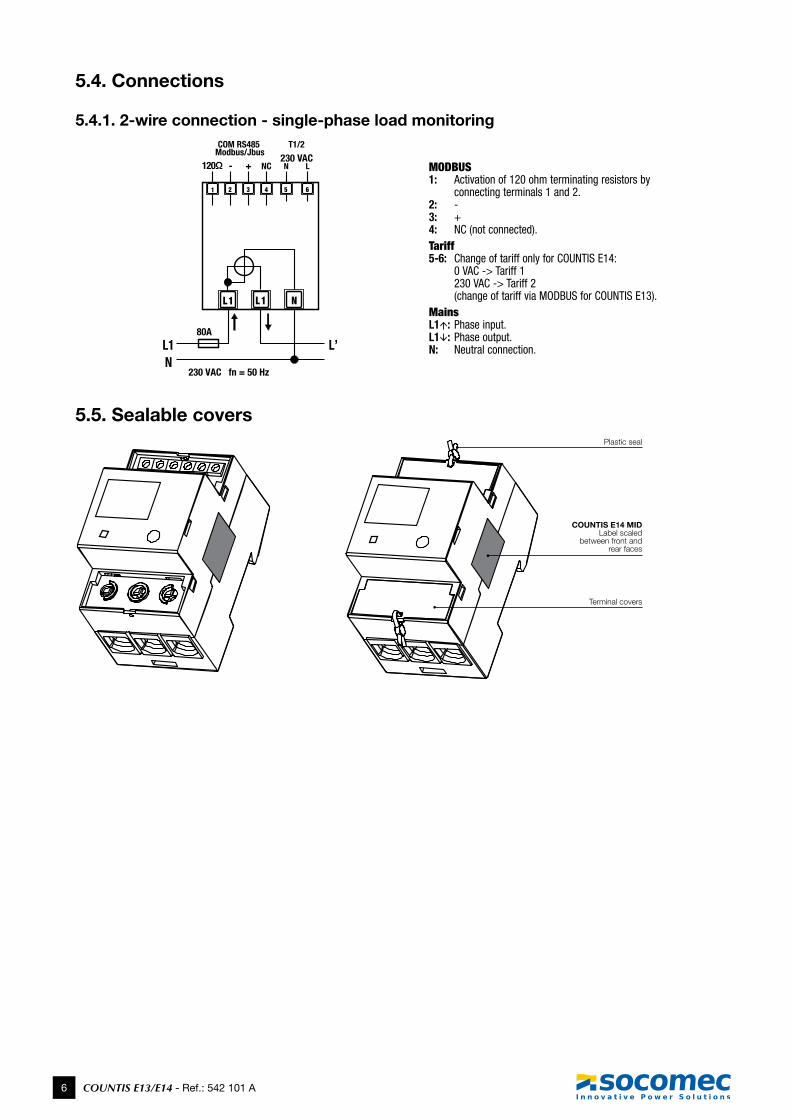
5.4. Connections
5.4.1. 2-wire connection - single-phase load monitoring
L1 L1 N
230 VAC fn = 50 Hz
L1 L’N
80A
61 5432
230 VAC120Ω - + NC
T1/2COM RS485 Modbus/Jbus
MODBUS1: Activation of 120 ohm terminating resistors by
connecting terminals 1 and 2.2: -3: +4: NC (not connected).Tariff5-6: Change of tariff only for COUNTIS E14:
0 VAC -> Tariff 1 230 VAC -> Tariff 2 (change of tariff via MODBUS for COUNTIS E13).
MainsL1: Phase input.L1: Phase output.N: Neutral connection.
5.5. Sealable covers
COUNTIS E14 MIDLabel scaled
between front and rear faces
Plastic seal
Terminal covers
7COUNTIS E13/E14 - Ref.: 542 101 A
COUNTIS E13/E14 MODBUS
6. MODBUS communication
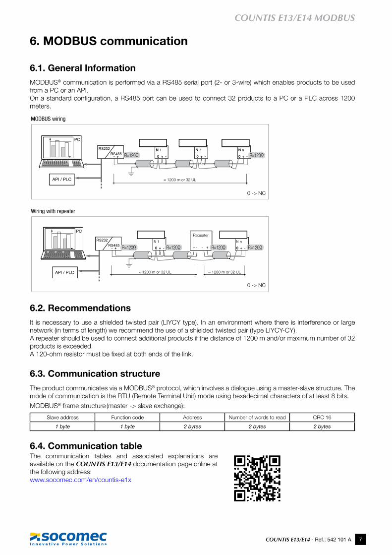
6.1. General InformationMODBUS® communication is performed via a RS485 serial port (2- or 3-wire) which enables products to be used from a PC or an API.Onastandardconfiguration,aRS485portcanbeusedtoconnect32productstoaPCoraPLCacross1200meters.
R=120Ω
R=120Ω
R=120Ω
R=120Ω R=120Ω R=120Ω
R=120Ω
R=120Ω
R=120Ω
R=120Ω R=120Ω R=120Ω
MODBUS wiring
Wiring with repeater
≈1200mor32UL
≈1200mor32UL ≈1200mor32UL
Repeater
0 -> NC
0 -> NC
6.2. RecommendationsIt is necessary to use a shielded twisted pair (LIYCY type). In an environment where there is interference or large network (in terms of length) we recommend the use of a shielded twisted pair (type LIYCY-CY).A repeater should be used to connect additional products if the distance of 1200 m and/or maximum number of 32 products is exceeded.A120-ohmresistormustbefixedatbothendsofthelink.
6.3. Communication structureThe product communicates via a MODBUS® protocol, which involves a dialogue using a master-slave structure. The mode of communication is the RTU (Remote Terminal Unit) mode using hexadecimal characters of at least 8 bits.
MODBUS® frame structure (master -> slave exchange):
Slave address Function code Address Number of words to read CRC 16
1 byte 1 byte 2 bytes 2 bytes 2 bytes
6.4. Communication tableThe communication tables and associated explanations are available on the COUNTIS E13/E14 documentation page online at the following address:www.socomec.com/en/countis-e1x
8 COUNTIS E13/E14 - Ref.: 542 101 A
7. Programming
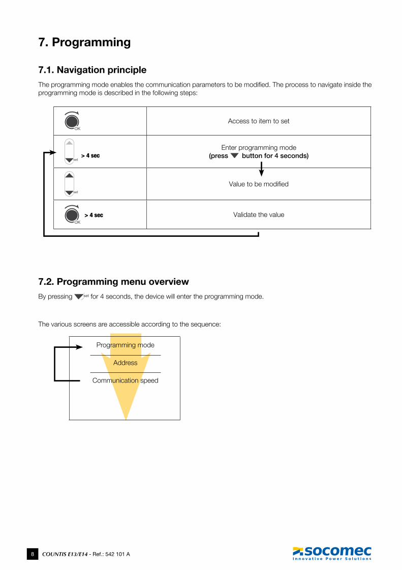
7.1. Navigation principleTheprogrammingmodeenablesthecommunicationparameterstobemodified.Theprocesstonavigateinsidetheprogramming mode is described in the following steps:
Access to item to set
> 4 secEnter programming mode
(press button for 4 seconds)
Value to be modified
> 4 sec Validate the value
7.2. Programming menu overviewBy pressing for 4 seconds, the device will enter the programming mode.
The various screens are accessible according to the sequence:
Programming mode
Address
Communication speed
9COUNTIS E13/E14 - Ref.: 542 101 A
COUNTIS E13/E14 MODBUS
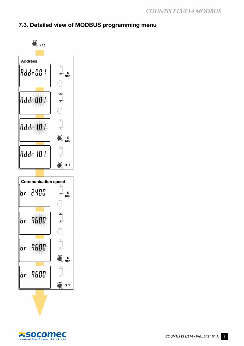
7.3. Detailed view of MODBUS programming menu
x 10
Address
4 sec
4 sec
x 1
Communication speed
4 sec
4 sec
x 1
10 COUNTIS E13/E14 - Ref.: 542 101 A
8. Operation
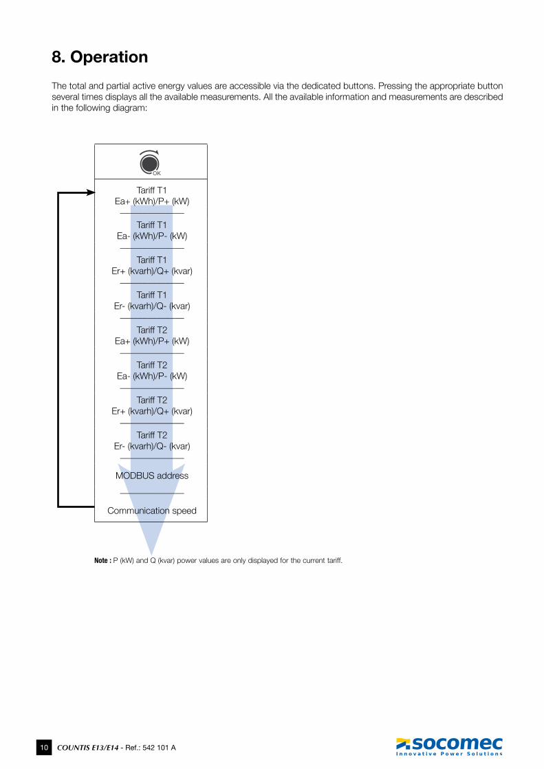
The total and partial active energy values are accessible via the dedicated buttons. Pressing the appropriate button several times displays all the available measurements. All the available information and measurements are described in the following diagram:
Tariff T1 Ea+ (kWh)/P+ (kW)
______________
Tariff T1 Ea- (kWh)/P- (kW)______________
Tariff T1 Er+ (kvarh)/Q+ (kvar)
______________
Tariff T1 Er- (kvarh)/Q- (kvar)
______________
Tariff T2 Ea+ (kWh)/P+ (kW)
______________
Tariff T2 Ea- (kWh)/P- (kW)______________
Tariff T2 Er+ (kvarh)/Q+ (kvar)
______________
Tariff T2 Er- (kvarh)/Q- (kvar)
______________
MODBUS address
______________
Communication speed
Note : P (kW) and Q (kvar) power values are only displayed for the current tariff.

11COUNTIS E13/E14 - Ref.: 542 101 A
COUNTIS E13/E14 MODBUS
8.1. Detailed view of menus
Ea+ (kWh)/P (kW) Tariff T1/T2*or
Ea- (kWh)/P (kW) Tariff T1/T2** Depending on the current tariff and energy x 1
Ea+ (kWh) Tariff T1Ea- (kWh) Tariff T1Er+ (kVarh) Tariff T1Er- (kVarh) Tariff T1Ea+ (kWh) Tariff T2Ea- (kWh) Tariff T2Er+ (kVarh) Tariff T2Er- (kVarh) Tariff T2P (kW) and Q (kvar) power values are only displayed for the current tariff
x 7
MODBUS
x 1
12 COUNTIS E13/E14 - Ref.: 542 101 A
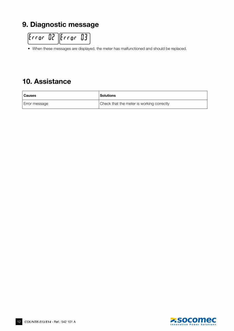
9. Diagnostic message
• When these messages are displayed, the meter has malfunctioned and should be replaced.
10. Assistance
Causes Solutions
Error message Check that the meter is working correctly
13COUNTIS E13/E14 - Ref.: 542 101 A
COUNTIS E13/E14 MODBUS
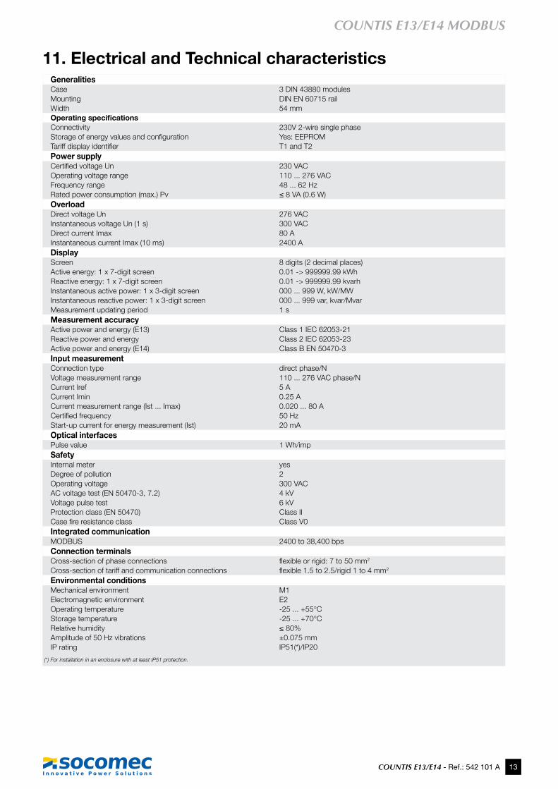
11. Electrical and Technical characteristicsGeneralitiesCase 3 DIN 43880 modulesMounting DIN EN 60715 railWidth 54 mmOperating specificationsConnectivity 230V 2-wire single phaseStorageofenergyvaluesandconfiguration Yes: EEPROMTariffdisplayidentifier T1 and T2 Power supplyCertifiedvoltageUn 230 VACOperating voltage range 110 ... 276 VACFrequency range 48 ... 62 HzRated power consumption (max.) Pv ≤8VA(0.6W)OverloadDirect voltage Un 276 VACInstantaneous voltage Un (1 s) 300 VACDirect current Imax 80 AInstantaneous current Imax (10 ms) 2400 ADisplay Screen 8 digits (2 decimal places) Active energy: 1 x 7-digit screen 0.01 -> 999999.99 kWh Reactive energy: 1 x 7-digit screen 0.01 -> 999999.99 kvarhInstantaneous active power: 1 x 3-digit screen 000 ... 999 W, kW/MWInstantaneous reactive power: 1 x 3-digit screen 000 ... 999 var, kvar/MvarMeasurement updating period 1 sMeasurement accuracyActive power and energy (E13) Class 1 IEC 62053-21Reactive power and energy Class 2 IEC 62053-23Active power and energy (E14) Class B EN 50470-3Input measurementConnection type direct phase/NVoltage measurement range 110 ... 276 VAC phase/NCurrent Iref 5 ACurrent Imin 0.25 A Current measurement range (Ist ... Imax) 0.020 ... 80 ACertifiedfrequency 50 HzStart-up current for energy measurement (Ist) 20 mAOptical interfacesPulse value 1 Wh/impSafetyInternal meter yesDegree of pollution 2Operating voltage 300 VACAC voltage test (EN 50470-3, 7.2) 4 kVVoltage pulse test 6 kVProtection class (EN 50470) Class IICasefireresistanceclass Class V0Integrated communicationMODBUS 2400 to 38,400 bpsConnection terminalsCross-section of phase connections flexibleorrigid:7to50mm2
Cross-section of tariff and communication connections flexible1.5to2.5/rigid1to4mm2
Environmental conditionsMechanical environment M1Electromagnetic environment E2Operating temperature -25 ... +55°CStorage temperature -25 ... +70°CRelative humidity ≤80%Amplitude of 50 Hz vibrations ±0.075 mmIP rating IP51(*)/IP20
(*) For installation in an enclosure with at least IP51 protection.
14 COUNTIS E13/E14 - Ref.: 542 101 A
12. MID compliance
The COUNTIS E14 meter complies with the MID directive for connection of single-phase networks (see "5.4. Connections", page 6).
Afterconnectingtheproduct,checkthattheterminalcoversarecorrectlyfittedandsecuredbythetwoplasticsealssupplied with the product (see "5.5. Sealable covers", page 6). If the terminal covers must be removed, ensure that seal part number 4850 304Uisused.
The information given via the communication bus is only sent by way of information and has no legal value.
TheassignedoperatingconditionsguaranteeingMIDcomplianceareavailableinthetechnicalspecificationstables.
The MID declaration of conformity for the COUNTIS E14 is available online at:www.socomec.com/en/countis-e1x

15COUNTIS E13/E14 - Ref.: 542 101 A
COUNTIS E13/E14 MODBUS
Ref
. 542
101
B -
EN
- 03
/14
www.socomec.com
hEAd offICE
SOCOMEC GROUPS.A. SOCOMEC capital 10 816 800€ R.C.S. Strasbourg B 548 500 149 B.P. 60010 - 1, rue de Westhouse F-67235 Benfeld Cedex - FRANCE Tel. +33 3 88 57 41 41 Fax +33 3 88 74 08 00 [email protected]
Socomec worldwide
BELGIUMCritical Power / Power Control & Safety / Energy Efficiency / Solar Power PowerTel. +32 2 340 02 30 Fax +32 2 346 28 99 [email protected]
FRANCECritical Power / Power Control & Safety / Energy Efficiency / Solar PowerTel. +33 1 45 14 63 00 Fax +33 1 48 67 31 12 [email protected]
GERMANyCritical PowerTel. +49 621 71 68 40 Fax +49 621 71 68 444 [email protected] Control & Safety / Energy EfficiencyTel. +49 7243 65292 0 Fax +49 7243 65292 13 [email protected]
ITALyCritical Power Tel.+39 02 98 242 942 Fax +39 02 98 240 723 [email protected] Control & Safety / Energy EfficiencyTel.+39 02 98 49 821 Fax +39 02 98 24 33 10 [email protected] PowerTel. +39 0444 598611 Fax +39 0444 598627 [email protected]
NETHERLANDSCritical Power / Power Control & Safety / Energy Efficiency / Solar PowerTel. +31 30 760 0900 Fax +31 30 637 2166 [email protected]
POLANDCritical PowerTel. +48 22 825 73 60 Fax. +48 22 825 73 60 [email protected] Control & Safety / Energy EfficiencyTel. +48 91 442 64 11 Fax +48 91 442 64 19 [email protected]
PORTUGALCritical Power / Solar PowerTel.+351 261 812 599 Fax +351 261 812 570 [email protected]
ROMANIACritical Power / Power Control & Safety / Energy Efficiency / Solar PowerTel. +40 21 319 36 88 Fax +40 21 319 36 89 [email protected]
RUSSIACritical Power / Power Control & Safety / Energy Efficiency / Solar PowerTel. +7 495 775 19 85 Fax +7 495 775 19 85 [email protected]
SLOVENIACritical Power / Power Control & Safety / Energy Efficiency / Solar PowerTel. +386 1 5807 860 Fax +386 1 561 11 73 [email protected]
SPAINCritical Power / Power Control & Safety / Energy Efficiency / Solar PowerTel. +34 93 540 75 75 Fax +34 93 540 75 76 [email protected]
TURKEyCritical Power / Power Control & Safety / Energy Efficiency / Solar PowerTel. +90 216 540 71 20-21-22 Fax +90 216 540 71 27 [email protected]
UNITED KINGDOMCritical PowerTel.+44 1285 863 300 Fax+44 1285 862 304 [email protected] Control & Safety / Energy EfficiencyTel. +44 1462 440 033 Fax +44 1462 431 143 [email protected]
Non
con
trac
tual
doc
umen
t. ©
201
4, S
ocom
ec S
A. A
ll rig
hts
rese
rved
. - T
o he
lp p
rote
ct th
e en
viro
nmen
t, th
is d
ocum
ent h
as b
een
prin
ted
on P
EfC
pap
er (P
rogr
amm
e fo
r th
e E
ndor
sem
ent o
f for
est C
ertif
icat
ion)
.
YoUR dISTRIBUToR
IN ASIA PACIfIC
AUSTRALIACritical PowerTel. +61 2 9325 3900 Fax +61 2 9888 9544 [email protected]
CHINACritical Power / Power Control & Safety / Energy EfficiencyTel. +86 21 52 98 95 55 Fax +86 21 62 28 34 68 [email protected]
INDIACritical Power / Solar PowerTel. +91 44 39215400 Fax +91 44 39215450 & 51 [email protected] [email protected] Control & Safety / Energy EfficiencyTel. +91 124 4027210 Fax +91 124 4562738 [email protected]
SINGAPORE Critical Power / Power Control & Safety / Energy EfficiencyTel.+65 6506 7600 Fax +65 64 58 7377 [email protected]
THAILANDCritical PowerTel. +66 2 941 1644 7 Fax +66 2 941 1650 [email protected]
VIETNAMCritical PowerTel. +84 8 3559 1220 Fax +84 8 3559 1221 [email protected]
IN MIddlE EAST
UNITED ARAB EMIRATESCritical Power / Power Control & Safety / Energy Efficiency / Solar PowerTel.+971 4 29 98 441 Fax +971 4 29 98 449 [email protected]
IN AMERICA
USA, CANADA & MEXICOPower Control & Safety / Energy EfficiencyTel. +1 617 245 0447 Fax +1 617 245 0437 [email protected]
oThER CoUNTRIES
NORTH AFRICAAlgeria / Morocco / [email protected]
AFRICAOther [email protected]
SOUTH EUROPECyprus / Greece / Israel / [email protected]
SOUTH AMERICATel. +34 93 540 75 75 [email protected]
MORE DETAILSwww.socomec.com/worldwide
IN EURoPE