counter pdf
TRANSCRIPT
8/3/2019 Counter PDF
http://slidepdf.com/reader/full/counter-pdf 1/3
cONSTRUcTION
108 • O ctO ber 2010 • electronics for you w w w . e f y m a g . c O m
HimansHu sHarma
Pulse Counterusing at89C4051
S u ni l K u ma r
Pulse counters are widely used in
our day-to-day life. Almost all
museums and theatres have a
visitor counter installed at entry/exit
to measure the visitor trafc. In indus-
tries, counting is done for production
control. Market tests too are performed
by counting the sold goods.
A pulse counter could be roughly
divided into three parts: a pulse
source, an electronic device that
counts, stores and prepares outputs,
and a display to show the accumulated
count.
This pulse counter is based on
Atmel AT89C4051 microcontroller.
TTL-logic-compatible pulses generated
by the source are fed to the counter
for counting. The AT89C4051 is a
low-voltage, high-performance, 8-bit
microcontroller with 4 kB of Flash
programmable and erasable read-only
memory, 128 bytes of RAM, 15 input/
output (I/O) lines, two 16-bit timers/
counters, a ve-vector, two-level inter-
rupt architecture, a full-duplex serial
port, a precision analogue comparator,
on-chip oscillator and clock circuitry.
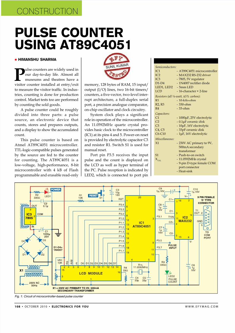
System clock plays a signicant
role in operation of the microcontroller.
An 11.0592MHz quartz crystal pro-
vides basic clock to the microcontroller
(IC1) at its pins 4 and 5. Power-on reset
is provided by electrolytic capacitor C3
and resistor R1. Switch S1 is used for
manual reset.
Port pin P3.5 receives the input
pulse and the count is displayed on
the LCD as well as hyper terminal of
the PC. Pulse reception is indicated by
LED2, which is connected to port pin
Fig. 1: Circuit of microcontroller-based pulse counter
Parts List
Semiconductors:
IC1 - AT89C4051 microcontroller
IC2 - MAX232 RS-232 driverIC3 - 7805, 5V regulator
D1-D4 - 1N4007 rectier diode
LED1, LED2 - 5mm LEDLCD - 16-character × 2-line
Resistors (all ¼-watt, ±5% carbon):
R1 - 10-kilo-ohm
R2, R3 - 330-ohmR4 - 33-ohm
Capacitors:
C1 - 1000μF, 25V electrolyticC2 - 0.1μF ceramic diskC3 - 10μF, 16V electrolytic
C4, C5 - 33pF ceramic diskC6-C10 - 1μF, 16V electrolytic
Miscellaneous: X1 - 230V AC primary to 9V,
500mA secondarytransformer
S1 - Push-to-on switchX
TAL- 11.0592MHz crystal
- 9-pin D-type female COMport connector
- Heat-sink
8/3/2019 Counter PDF
http://slidepdf.com/reader/full/counter-pdf 2/3
cONSTRUcTION
electronics for you • O ctO ber 2010 • 10 9w w w . e f y m a g . c O m
LED1 acts as the power indicator andR2 limits the current through LED1.
Cc d
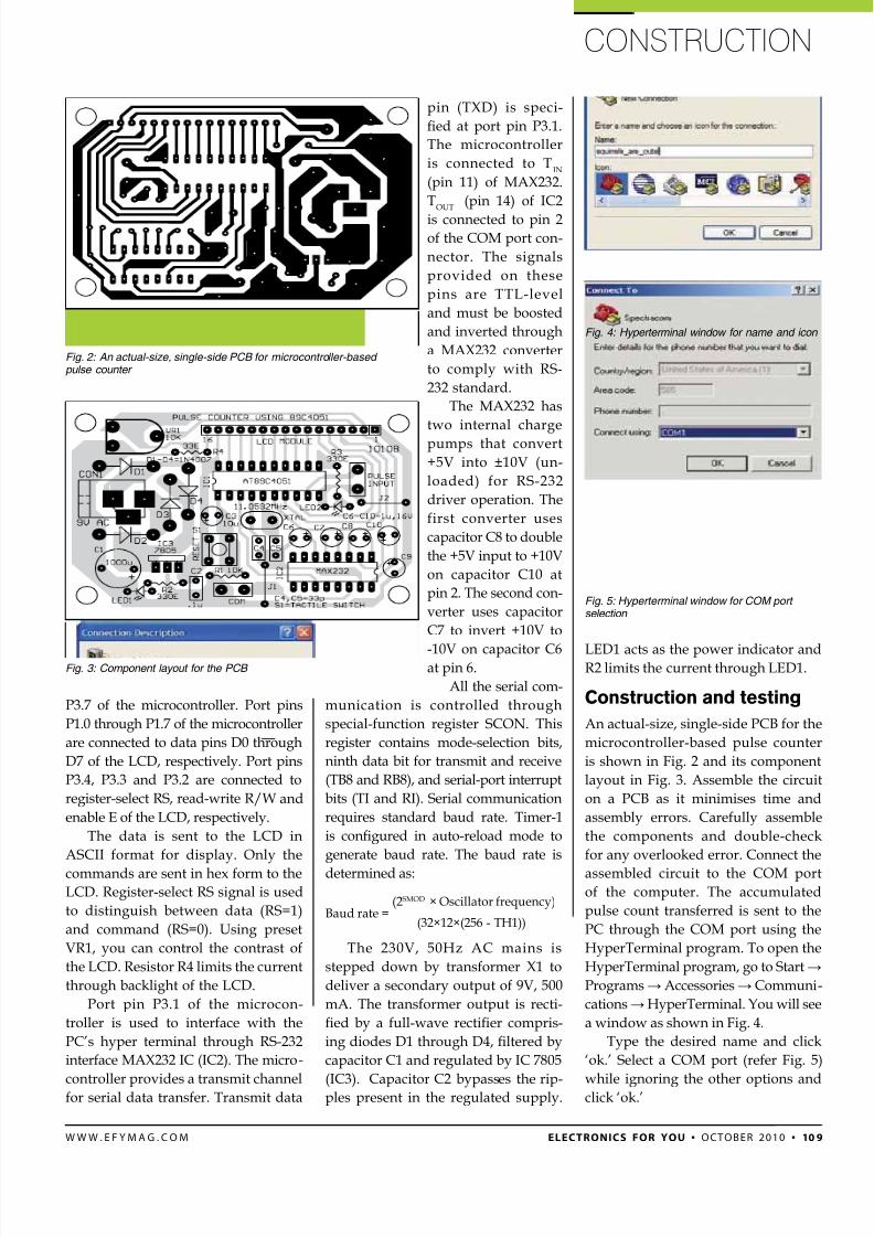
An actual-size, single-side PCB for the
microcontroller-based pulse counter
is shown in Fig. 2 and its component
layout in Fig. 3. Assemble the circuit
on a PCB as it minimises time and
assembly errors. Carefully assemble
the components and double-check
for any overlooked error. Connect the
assembled circuit to the COM port
of the computer. The accumulated
pulse count transferred is sent to the
PC through the COM port using the
HyperTerminal program. To open the
HyperTerminal program, go to Start →
Programs → Accessories → Communi-
cations → HyperTerminal. You will see
a window as shown in Fig. 4.
Type the desired name and click
‘ok.’ Select a COM port (refer Fig. 5)
while ignoring the other options andclick ‘ok.’
P3.7 of the microcontroller. Port pins
P1.0 through P1.7 of the microcontroller
are connected to data pins D0 through
D7 of the LCD, respectively. Port pins
P3.4, P3.3 and P3.2 are connected to
register-select RS, read-write R/W and
enable E of the LCD, respectively.
The data is sent to the LCD in
ASCII format for display. Only the
commands are sent in hex form to the
LCD. Register-select RS signal is used
to distinguish between data (RS=1)
and command (RS=0). Using preset
VR1, you can control the contrast of
the LCD. Resistor R4 limits the current
through backlight of the LCD.
Port pin P3.1 of the microcon-
troller is used to interface with the
PC’s hyper terminal through RS-232
interface MAX232 IC (IC2). The micro-
controller provides a transmit channelfor serial data transfer. Transmit data
pin (TXD) is speci-
ed at port pin P3.1.
The microcontroller
is connected to TIN
(pin 11) of MAX232.
TOUT
(pin 14) of IC2
is connected to pin 2of the COM port con-
nector. The signals
provided on these
pins are TTL-level
and must be boosted
and inverted through
a MAX232 converter
to comply with RS-
232 standard.
The MAX232 has
two internal charge
pumps that convert
+5V into ±10V (un-
loaded) for RS-232
driver operation. The
first converter uses
capacitor C8 to double
the +5V input to +10V
on capacitor C10 at
pin 2. The second con-
verter uses capacitor
C7 to invert +10V to
-10V on capacitor C6at pin 6.
All the serial com-
munication is controlled through
special-function register SCON. This
register contains mode-selection bits,
ninth data bit for transmit and receive
(TB8 and RB8), and serial-port interrupt
bits (TI and RI). Serial communication
requires standard baud rate. Timer-1
is congured in auto-reload mode to
generate baud rate. The baud rate is
determined as:
Baud rate =(32×12×(256 - TH1))
(2SMOD × Oscillator frequency)
The 230V, 50Hz AC mains is
stepped down by transformer X1 to
deliver a secondary output of 9V, 500
mA. The transformer output is recti-
ed by a full-wave rectier compris-
ing diodes D1 through D4, ltered by
capacitor C1 and regulated by IC 7805
(IC3). Capacitor C2 bypasses the rip-ples present in the regulated supply.
Fig. 4: Hyperterminal window for name and icon
Fig. 2: An actual-size, single-side PCB for microcontroller-based pulse counter
Fig. 3: Component layout for the PCB
Fig. 5: Hyperterminal window for COM port selection
8/3/2019 Counter PDF
http://slidepdf.com/reader/full/counter-pdf 3/3
cONSTRUcTION
110 • O ctO ber 2010 • electronics for you w w w . e f y m a g . c O m
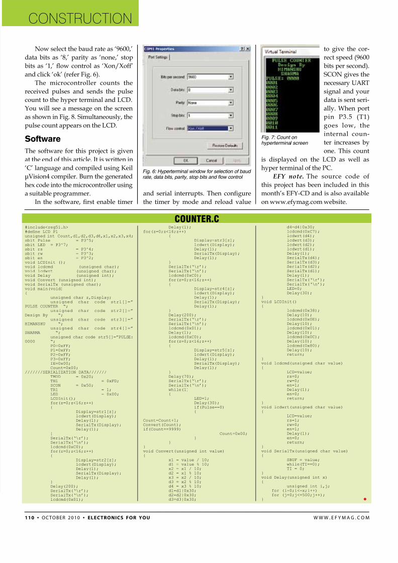
to give the cor-
rect speed (9600
bits per second).
SCON gives the
necessary UART
signal and your
data is sent seri-ally. When port
pin P3.5 (T1)
goes low, the
internal coun-
ter increases by
one. This count
is displayed on the LCD as well as
hyper terminal of the PC.
EFY note. The source code of
this project has been included in this
month’s EFY-CD and is also available
on www.efymag.com website.
and serial interrupts. Then congure
the timer by mode and reload value
counter.c
Fig. 6: Hyperterminal window for selection of baud rate, data bits, parity, stop bits and fow control
Fig. 7: Count on hyperterminal screen
Now select the baud rate as ‘9600,’
data bits as ‘8,’ parity as ‘none,’ stop
bits as ‘1,’ ow control as ‘Xon/Xoff’
and click ‘ok’ (refer Fig. 6).
The microcontroller counts the
received pulses and sends the pulse
count to the hyper terminal and LCD.You will see a message on the screen
as shown in Fig. 8. Simultaneously, the
pulse count appears on the LCD.
sfw
The software for this project is given
at the end of this article. It is written in
‘C’ language and compiled using Keil
μVision4 compiler. Burn the generated
hex code into the microcontroller using
a suitable programmer.
In the software, rst enable timer
#include<reg51.h>#dene LCD P1unsigned int Count,d1,d2,d3,d4,x1,x2,x3,x4;sbit Pulse = P3^5;sbit LED = P3^7;sbit rs = P3^4;sbit rw = P3^3;sbit en = P3^2;void LCDInit ();void lcdcmd (unsigned char);void lcdwrt (unsigned char);void Delay (unsigned int);void Convert (unsigned int);void SerialTx (unsigned char);void main(void){
unsigned char z,Display;unsigned char code str1[]=”
PULSE COUNTER “;unsigned char code str2[]=”
Design By “;unsigned char code str3[]=”
HIMANSHU “;unsigned char code str4[]=”
SHARMA “;unsigned char code str5[]=”PULSE:
0000 “;P0=0xFF;P1=0xFF;P2=0xFF;P3=0xFF;IE=0x00;Count=0x00;
///////SERIALIZATION DATA///////TMOD = 0x20;TH1 = 0xFD;SCON = 0x50;TR1 = 1;
LED = 0x00;LCDInit();for(z=0;z<16;z++){
Display=str1[z];lcdwrt(Display);Delay(1);SerialTx(Display);Delay(1);
}SerialTx(‘\r’);SerialTx(‘\n’);lcdcmd(0xC0);for(z=0;z<16;z++){
Display=str2[z];lcdwrt(Display);Delay(1);SerialTx(Display);Delay(1);
}Delay(200);SerialTx(‘\r’);
SerialTx(‘\n’);lcdcmd(0x01);
Delay(1);for(z=0;z<16;z++)
{Display=str3[z];lcdwrt(Display);Delay(1);SerialTx(Display);Delay(1);
}SerialTx(‘\r’);SerialTx(‘\n’);lcdcmd(0xC0);for(z=0;z<16;z++){
Display=str4[z];lcdwrt(Display);
Delay(1);SerialTx(Display);Delay(1);
}Delay(200);SerialTx(‘\r’);SerialTx(‘\n’);lcdcmd(0x01);Delay(1);lcdcmd(0xC0);for(z=0;z<16;z++){
Display=str5[z];lcdwrt(Display);Delay(1);SerialTx(Display);Delay(1);
}Delay(70);SerialTx(‘\r’);SerialTx(‘\n’);while(1)
{ LED=1;Delay(30);if(Pulse==0){
Count=Count+1;Convert(Count);if(Count==9999)
Count=0x00;}
}}void Convert(unsigned int value){
x1 = value / 10;d1 = value % 10;x2 = x1 / 10;d2 = x1 % 10;x3 = x2 / 10;d3 = x2 % 10;d4 = x3 % 10;d1=d1|0x30;
d2=d2|0x30;d3=d3|0x30;
d4=d4|0x30;lcdcmd(0xC7);lcdwrt(d4);lcdwrt(d3);lcdwrt(d2);lcdwrt(d1);Delay(1);SerialTx(d4);SerialTx(d3);SerialTx(d2);SerialTx(d1);Delay(1);SerialTx(‘\r’);SerialTx(‘\n’);LED=0;Delay(30);
}void LCDInit(){
lcdcmd(0x38);Delay(10);lcdcmd(0x0E);Delay(10);lcdcmd(0x01);Delay(10);lcdcmd(0x0C);Delay(10);lcdcmd(0x80);Delay(10);return;
}void lcdcmd(unsigned char value){
LCD=value;rs=0;rw=0;en=1;Delay(1);
en=0;return;}void lcdwrt(unsigned char value){
LCD=value;rs=1;rw=0;en=1;Delay(1);en=0;return;
}void SerialTx(unsigned char value){
SBUF = value;while(TI==0);TI = 0;
}void Delay(unsigned int x){
unsigned int i,j;for (i=0;i<=x;i++)
for (j=0;j<=500;j++);}