cosmac vip manual (pdf) - chip8.com
TRANSCRIPT


RCA COSMAC VIP CDP18S711Instruction Manual
RCA Solid State Division, Somerville, N. J. 08876
Copyright 1978 by RCA Corporation(All rights reserved under Pan-American Copyright Convention)
Printed in USA/2-78
VIP-311

ACKNOWLEDGMENT
COSMAC VIP has been created by Joe Weisbecker ofthe RCA Laboratories, Princeton, N.J. so that everyone canhave fun and useful personal computer experiences. Theelegant and simple hardware system design and thepowerful video output together with the customized CHIP-8language interpreter constitute a fresh and promisingapproach to personal computers.
If questions arise regarding the VIP software orhardware, write to
VIPRCA Solid State DivisionBox 3200Somerville, N.J. 08876
or telephoneArea code 201 526-6141
Information furnished by RCA is believed to be accurateand reliable. However, no responsibility is assumed byRCA for its use; nor for any infringements of patents orother rights of third parties which may result from its use.No license is granted by implication or otherwise underany patent or patent rights of RCA.
Trademarks Registered
Marca(s) Registrada(s)

Contents
I. Getting Started ...................................................................................................................5What This Manual Covers .................................................................................................5The Power Supply ..............................................................................................................6What You See .....................................................................................................................7Turning It On ......................................................... ......................................................7
II. COSMAC VIP Operation ..................................................................................................9Using the Operating System .............................................................................................9Memory Write ........................................................ .............................. ............................9Memory Read ......................................................... ............................. .......................... 10Tape Write .............................................................. ....................................................... 10Tape Read ............................................................... ....................................................... 10Testing Your Cassette System ............................... ....................................................... 11
III. CHIP-8 Language Programming .......................... ....................................................... 13Branch Instructions ............................................... ....................................................... 13How to Change and Use the Variables ................. ....................................................... 13Using the Display Instructions .............................. ....................................................... 14Applying CHIP-8 .................................................... ....................................................... 16Some Program Ideas .............................................. ....................................................... 17
IV. Machine Language Programming ................................................................................. 19VIP Machine Coding ...................................................................... ................. .............. 19Putting Machine Coding and CHIP-8 Language Together ......... ............................... 19Machine Language Programming Summed Up ........................... ............................... 20
V. Logic Description ............................................................................ .............. ................. 21How Memory is Addressed ............................................................ ............................... 21How the Input/Output Works ........................................................ ............................... 21
VI. Expansion Considerations and Connections ................................. ............................... 23Using the Byte Input/Output .......................................................... ............................... 23Using the Expansion Interface ....................................................... ............................... 24Some Expansion Ideas .................................................................... ............................... 24
VII. Troubleshooting Hints ................................................................................................... 27No Sound ......................................................................................................................... 27No Display ....................................................................................................................... 27Other Problems .............................................. ................................. .............................. 27Signal Tracing ................................................ ............................................................... 27Last Resorts .................................................... ............................................................... 28
Appendix A - Test and Operating Data ................... ............................................................... 29Byte Pattern for Displaying "COSMAC" .... ............................................................... 29Beeper Program ............................................. ............................................................... 29Cassette Attachment Diagram ...................... ............................................................... 30Cassette Phase Test ........................................ ............................................................... 30Cassette Data Test .......................................... ..................... .......................................... 31Cassette Recording Guidelines ...................... ............................................................... 32Memory Test Program................................................ .................................................... 32

Contents (Continued)
Appendix B - Operating System ................................................................................................. 33Operating System Listing ................................................................................................. 33Operating System Register Table .................................................................................... 34Operating System Summary ............................................................................................ 34
Appendix C - CHIP-8 Interpreter ................................................. ............................................35CHIP-8 Interpreter Listing ................................................. ............................................35CHIP-8 Memory Map .......................................................... ............................................36CDPI802 Register Use for CHIP-8 Interpreter ................. ............................................36CHIP-8/Operating System Standard Digit Display Format ..........................................37CHIP-8 User Notes ........................................................................... ....... .........................38
Appendix D - Video Games ........................................................................ ................................391. VIP Kaleidoscope ......................................................................... ................. ...............402. VIP Video Display Drawing Game ............................................. ................. ...............413. VIP Wipe Off ................................................................................ ................. ...............424. VIP Space Intercept ..................................................................... ................. ...............435. VIP 4096-Bit Picture .................................................................... ................. ...............446. VIP Figure Shooting at Moving Target ...................................... ................. ...............457. VIP Tick-Tack-Toe Game ...................................................... .....................................468. VIP Spooky Spot ..................................................................... ................. ....................489. VIP Jackpot ............................................................................. ................. ....................4910. VIP Snake Race ..................................................................... ................. ....................5111. VIP Card Matching Game ................................................... ................. ....................5212. VIP Armored Vehicle Clash ................................................. ................. ....................5413. VIP Hi-Lo .................................................................................... ................. ...............5614. VIP Hex Reflex ........................................................................... ................. ...............5715. VIP Dot-Dash .............................................................................. ................. ...............5816. VIP A-Mazing ............................................................................. ................. ...............6017. VIP Deduce ................................................................................. ................. ...............6218. VIP Shooting Stars ..................................................................... ................. ...............6319. VIP Strike-9 ................................................................................ ................. ...............6420. VIP Card Game (like the well-known acey-ducey) ................. ................. ...............66
Appendix E - Logic Diagrams .................................................................... ................................67Fig. E-1 - Microprocessor and Display Interface Circuits ............ ................................68Fig. E-2 - ROM Circuits and Expansion Interface ........................ ................................69Fig. E-3 - Keyboard, Decoding, Audio Oscillator, and Cassette
Interface Circuits ............................................................ ................................70Fig. E-4 - RAM Circuits ........................................ ...........................................................71Fig. E-5 - Power Supply Circuit and Byte Input/Otaput Interface ...............................72
Appendix F - Board Layout, Parts List, and Assembly Instructions ........................................731. Printed Circuit Board Layout ......................................................................................742. Parts List for RCA COSMAC VIP CDP18S711 .........................................................753. COSMAC VIP Expansion Notes ..................................................................................77
a. Soldering the PC Board ..................................................................................77b. Voltage Regulator Option ..............................................................................77c. Additional 2048-Byte RAM Option ...............................................................77
Appendix G - Data Sheets .............................................................................................................79CDP 1832 512-Word x 8-Bit Static Read-Only Memory ...............................................81CDP 1861 Video Display Controller (Video Interface) ..................................................85CDP 1802 COSMAC Microprocessor .............................................................................97

1
1. Getting Started
COSMAC VIP (Video Interface Processor)CDP18S711 is a complete computer on a singleprinted-circuit card. It includes the following:
*RCA CDP1802 Microprocessor (91 instructions)*2048-byte RAM*Built-in hex keyboard (modern reliable touchpad
type)*Graphic video display interface (standard video
output)*100-byte-per-second audio cassette interface*Regulated power supply (wall-pack type)*Crystal clock*Sound circuits (for signal tones and games)*512-byte ROM operating system*Comprehensive documentation*20 ready-to-use video game programs*Unique CHIP-8 language (31 easy-to-use in-
structions)*On-card RAM expansion up to 40% bytes*On-card parallel 1/0 port*Connector for extensive external expansion
capability
COSMAC VIP was designed for home hobby use. Justadd an inexpensive video display and an audio cassetterecorder for program storage. You don't need expensive,hidden extras such as power supply, computer terminal,external keyboard, or additional RAM. COSMAC VIPprovides everything needed for years of creativecomputer fun for the whole family. With COSMAC VIPyou're immediately ready to play video games,experiment with computer art or animation, write yourown programs with a new language called CHIP-8, or gethands-on experience using machine language.
With COSMAC VIP you can easily create pictureson the display screen and move them around. Thisfeature is invaluable for video games and not usuallyavailable with computers costing several times asmuch. The software you need to use your computer isprovided free instead of at added cost or not at all.Simplified operation was a primary design goal sothat you don't have to waste a lot of time learning andremembering complex operating procedures.COSMAC VIP uses state-of-the-art devices coupledwith an efficient design. Full expansion capabilityallows you to inexpensively tailor COSMAC VIP tospecific applications such as model railroad control,music synthesis, or color graphics. You will soon.discover that COSMAC VIP provides a refreshinglynew, lower-cost alternative to conventional computerswhich have been aimed more toward mathematicsand business than fun.
What This Manual CoversT'his manual serves several purposes. It lets you get
started playing video games with minimum effort. justset up your system as described in this section and learnhow to use the operating system and cassette interface asdescribed in the next section. You can immediately useall the video games in Appendix D without going anyfurther.
If you want to learn to write your own programs,Section III describes an easy language to start with calledCHIP-8. Most of the programs in Appendix D weredesigned using this language. CHIP-8 looks somewhatlike machine language but is quicker to learn and easierto use than many of the more common high-levellanguages. It also requires much less RAM, which save8you a lot of money.

6
CHIP-8 includes a real time clock, random numbergenerator, decimal conversion, and digit or graphicdisplay capability. It only uses 512 bytes of RAM leavingover 1024 bytes for programs in a 2048-byte system.(You can get an additional 2048 bytes of RAM byplugging four more RAM chips into your card.)
With the aid of the User Manual for the CDPI802COSMAC Microprocessor, MPM-201, you can explorethe fascinating world of machine language programming.You can even combine, machine language programs withCHIP-8 programs or develop your own interpretivelanguages.
For hardware hackers, COSMAC VIP providescomplete external interface capabilities. Somesuggestions for inexpensive external devices andapplications are listed in Section VI. Logic diagrams,data sheets, trouble -shooting hints, and test programs areprovided so that you can explore the hardware in as muchdetail as you want.
This manual assumes that you are familiar withcomputer basics from reading one or more of theexcellent magazines devoted to home computing. Youshould understand RAM, ROM, memory addressing,instructions, bytes, etc. The use of a scope
RCA COSMAC VIP Instruction Manual
will facilitate setting up the cassette system and iden-tifying hardware problems in the rare case where theyoccur. Hex notation is used in this manual unless notedotherwise. (One byte equals two hex digits.)
The Power Supply
The output wires of the internally regulated powerconverter supplied with the COSMAC VIP CDP18S711are connected to the +V DC and GND pads at the backleft comer of the PC card. The power converter output isregulated +5 V DC at 600 mA. If you wish to add moreRAM to your system, however, you may need ahigher-current power supply. A 2048-byte systemrequires about 350 mA (600 mA worst case). A4096-byte system should require average current ofabout 600 mA. If, however, your RAM chips requireabove average power, you may need to supply as muchas 900 mA at 5 V DC, regulated. You can also use yourown unregulated 8 to 10 V DC power supply by addingvoltage regulator U28 (plus heatsink) to your COSMACVIP card and cutting the printed circuit link called LKI.Never apply more than +5 V DC to the card unless theU28 regulator has been added and link LKI cut.
Photograph of COSMAC VIP (Video Interface Processor) CDP18S711 Thecables in the upper right are for the video display and for cassetteoperation. Cable on the upper left goes to the power converter.

After completing the above set-up procedure, you are ready to enter and run programs on your COSMAC VIP.The COSMAC VIP operating system, explained in thenext section, permits you to load programs into memoryfrom the hex keyboard, verify them, and record themon cassettes for later reuse.
1. Getting Started 7
What You SeeYou must now decide on the video display for your
computer. The video pad at the back right comer of theCOSMAC VIP card provides a video signal which youcan connect directly to the high-impedance input of moststandard video monitors. The horizontal sync frequencyis 15,720 Hz and the vertical sync frequency is 60 Hz.One solution to your video display need is a commercialvideo monitor having a suitable input -- not rf or antennainput. Another option is your TV receiver used with arelatively inexpensive FCC-approved modulator. Do notuse a standard TV receiver with the VIP output connectedto the VHF or UHF antenna terminals. Do not usetransformerless TV receivers.
Turning It OnAfter attaching a suitable video display, apply power.
Make sure the RUN switch is in the down (or reset)position. Hold hex key C down while you flip the RUNswitch up. You should hear a tone with key
C pressed and the Q light should be on. When you releasekey C the tone and Q light should both go off. (The toneoccurs whenever the Q light is on.) You should now see arandom pattern of small square spots on the display. Pushhex keys 8008 in sequence and you should see 8008 atthe bottom left of the screen and 64 at the lower right.Adjust your display controls for the best picture (whitespots on a-black background). You can experiment withchanging the values of RI, R2, and R4 on the COSMACVIP card to improve picture quality although this stepshouldn't be necessary. Certain modulators work betterwith an R4 of 1 kilohm instead of 200 ohms. If you don'tget a video picture refer to Section VII fortroubleshooting hints.

11. COSMAC VIP Operation
COSMAC VIP is operated with the RUN switch andhex keyboard. The PWR light shows that power is on.The Q light is activated by various programs. A tone issounded whenever the Q light is on. The TAPE lightglows when cassette input data is present. When usingCOSMAC VIP, always start with the RUN switch in thedown (or reset) position. Flipping the RUN switch upinitiates execution of machine language programsbeginning at memory location 0000. If you havepreviously stored the CHIP-8 Ian_ guage interpreterprogram at locations 0000-01FF, execution of a programwritten in this language will begin at 0200. To manuallyterminate execution of any program, flip RUN down.
Using the Operating SystemWith COSMAC VIP you can load programs into
memory from the hex keyboard or cassette recorder,record the contents of memory on cassettes, show thecontents of memory bytes in hex form on the display,and examine the contents of CDP1802 microprocessorregisters. These functions are performed with the aid of aspecial program called an operating system. Thisoperating system is contained in a ROM so that it's readyto use as soon as power is turned on. It is located atmemory locations 8000-81FF. A machine code listingand summary of this operating system is provided inAppendix B.
To use the operating system hold key C down on thehex keyboard when you flip RUN up. You will hear atone. Release key C and you're ready to use theoperating system.
After selecting the operating system you can do fourdifferent operations as shown in the following table:
9
KEY OPERATION
0AFB
MW (Memory Write)MR (Memory Read)TW (Tape Write) TR(Tape Read)
For any of these operations you must first enter amemory address. Enter the 4 hex digits of any memoryaddress using the hex keyboard (most significant digitfirst). You will see the address at the lower left of thescreen and the byte contained in that address at the lowerright. Remember that addresses and bytes are alwaysentered and shown in hex form. Suppose you entered0200. You will see 0200 at the bottom left of the screenand the byte stored at 0200 at the lower right.
Memory WriteIf you want to change this byte, press the 0 key. Now
press two digits of the new byte (most significant digitfirst) and it will be stored at 0200 replacing the originalbyte. You will see this change on the screen. If you enteranother byte it will be shown and stored at the nexthigher address in sequence (0201 in this example). Youcan load any, sequence of bytes directly from the hexkeyboard in this manner. If you make a mistake, flipRUN down. With key C pressed, flip RUN back up.Enter the address at which you made the error. Press key0 and resume entering your program.
Note the random bit pattern on the screen above thehex display. This pattern is the binary data

10
contained in the last 256-byte page of the on-card RAM.If you have a 2048-byte RAM, you are seeing locations0700-7FF on the screen. Bit 7 of the byte at 0700 is inthe upper left comer. Try storing a sequence of eight AAbytes followed by eight 55 bytes starting at location0700. Keep repeating this sequence to draw acheckerboard pattern on the screen. There are 32 rows ofspots on the screen. Each row represents 8 memory bytes(64 bits). Locations 0700-0707 are shown in the top row,0708-07OF in the next row down. Draw a bit map onpaper and you can construct pictures on the TV screen byentering the proper byte sequences. The byte pattern fordisplaying the word COSMAC is shown in Appendix A.
Memory ReadSuppose you wish to examine the contents of a
memory location. Flip RUN up while pressing key C.Enter the address of the location you want to examine.Press key A for the Memory Read mode. You will seethe memory address and the byte stored at that addresson the screen. Press any hex key to step through memoryand see the contents. Memory locations examined areleft unchanged. If a program doesn't run properly youcan use this mode to verify that it was stored correctly inmemory.
You can now enter and run the short beeper programshown in Appendix A. Flip RUN up with key C pressed.Release key C and enter address 0000. Press key 0 toselect the Memory Write mode. Now enter the beeperprogram one byte at a time using the hex keyboard. FlipRUN down to reset the computer. Flip RUN up toexecute the beeper program you just loaded intolocations 0000-OOOC. You can load and run anyCOSMAC VIP program in this manner. For most of thegame programs you will first have to load the CHIP-8interpreter (Appendix C) into locations 0000-OIFFfollowed by the game program starting at location 0200.
Tape WriteAny program you load into memory will be lost when
you turn off power. Unless it is safely stored, you willhave to key it in by hand again the next time you want touse it. The cassette interface is provided so that afterkeying in a program you can then record it on an audiocassette; and when you want to use the program again,all you have to do is play it back into the memory fromthe cassette. This playback usually takes less than 30seconds.
The COSMAC VIP cassette interface was designed towork with most standard audio cassette recorders.Panasonic models RQ-309DS, RQ-212D, and RQ-413Shave yielded satisfactory results as has the Sony
RCA COSMAC VIP Instruction Manual
TC-150. In general, better quality recorders providemore reliable operation.
Your tape recorder must have an 8-ohm earphone orexternal speaker jack and a microphone input jack.Connect the cassette recorder to the COSMAC VIPtape-in tape-out pads on the right-hand side of the card asshown in the cassette attachment diagram in AppendixA.
After properly connecting your cassette recorder youcan try recording and playing back a cassette using theoperating system as described below. Follow the cassetterecording guidelines provided in Appendix A for bestresults. If you run into trouble, use the cassette phase anddata test procedures described in Appendix A fortroubleshooting.
The memory is divided into 256-byte pages forrecording. You can record 1 to 15 consecutive pages ontape. The low-order byte of your starting address shouldbe 00. Select the operating system by holding key Cdown while flipping RUN up. Enter the 4-digit addressof the first page to be recorded on tape. Press key F andyou're ready to record. Rewind a blank cassette and placeyour cassette unit in the record mode. Wait about 10seconds and tap the hex key that represents the numberof pages you want to record on tape. The screen will goblank and you'll hear a tone while recording. When thespecified number of pages has been recorded on thecassette, the tone will end and the last memory byterecorded on tape will be shown on the screen.
Tape ReadTo load memory from a previously recorded cassette,
first select the operating system (RUN and key C). Enterthe memory address of the first page to be loaded(usually 0000). Press key B to select the Tape Readmode. Rewind and play the cassette. Immediately pressthe hex key representing the number of pages you wantto load into memory from the cassette. The tape recordertone control should be set to maximum high. The volumecontrol should be set for a steadily glowing tape lightwhen data is being read from the tape. The screen will goblank while the program is loaded from the tape intomemory. It will show the last byte loaded into memoryat the end of loading.
If the Q light and tone come on while a tape is beingread, an error occurred. Flip RUN down, rewind thecassette, and try again. You may h ' ave to readjust thecassette volume control. Be sure that the cassettecontains at least as many pages as you specify to beloaded. For most of the game programs, load theCHIP-8 interpreter program (Appendix C) into 0000-

After recording and checking a program cassette, you canbreak out the tabs at the top of the cassette to preventaccidental erasure. In the event you wish to record on acassette after you have broken out the tabs, you can do sosimply by pasting tape over the tab holes. You can record andkeep your own cassette software library starting with the gameprograms in Appendix D. Cassette recording or playbackshould require 5 + 2.5N seconds. N is the number of pagesrecorded on tape. Recording or loading the entire 2048-byteRAM (8 pages) will require less than 30 seconds. Ile nextsection describes how you can design your own programsusing a unique easy-to-learn programming language calledCHIP-8.
11. COSMAC VIP Operation 1
01FF, then load the game program starting at 0200.Record a cassette from 0000 to the end of the gameprogram. When you load this tape, starting at 0000, youwill be ready to play the game.
Testing Your CassetteSystem
Test your cassette system by entering the beeperprogram at 0000 (Appendix A). Store 25 at 06FF. Nowrecord 7 pages on a cassette starting at 0000. Load these7 pages back into memory from the cassette starting at0000. If no errors occur you should see "06FF 25" onthe screen after loading is complete. Flip RUN down,then up, and the beeper program should be running.

III. CHIP-8 Language Programming
CHIP-8 is an easy-to-learn programming languagethat lets you write your own programs. To use theCHIP-8 language, you must first store the 512-byteCHIP-8 language program at memory locations 0000 to01FF. The CHIP-8 language program is shown inAppendix C in hex form so you can enter it directly inmemory using the hex keyboard. You can then record iton a memory cassette for future use. Each CHIP-8instruction is a two-byte (4-hex-digit) code. There are31, easy-to-use CHIP-8 instructions as shown in Table L
When using CHIP-8 instructions your program mustalways begin at location 0200. There are 16 one-byte variables labeled 0-F. VX or VY refers to the valueof one of these variables. A 63FF instruction setsvariable 3 to the value FF (V3=FF). I is a memorypointer that can be used to specify any location in RAM.An A232 instruction would set I= 0232. 1 would thenaddress memory location 0232.
Branch InstructionsThere are several types of jump or branch instructions
in the CHIP-8 language. Instruction 1242 would causean unconditional branch to the instruction at memorylocation 0242. Instruction BMMM lets you index thebranch address by adding the value of variable 0 to itbefore branching. Eight conditional skip instructions letyou test the values of the 16 one-byte variables ordetermine if a specific hex key is being pressed. Thislatter capability is useful in video game programs. (Onlythe least significant hex digit of VX is used to specifythe key.)
A 2570 instruction would branch to a subroutinestarting at location 0570. 00EE at the end of thissubroutine will return program execution to the
instruction following the 2570. The subroutine itselfcould use another 2MMM instruction to branch to (orcall) another subroutine. This technique is known assubroutine nesting. Note that all subroutines called (orbranched to) by 2MMM instructions must end with00EE. Ignoring this rule will cause hard-to-findprogram bugs.
How to Change andUse the Variables
The CXKK instruction sets a random byte value intoVX. This random byte would have any bits matching 0bit positions in KK set to 0. For example, a C407instruction would set V4 equal to a random byte valuebetween 00 and 07.
A timer (or real-time clock) can be set to any valuebetween 00 and FF by a FX15 instruction. This timer isautomatically decremented by one, 60 times per seconduntil it reaches 00. Setting it to FF would require about 4seconds for it to reach 00. This timer can be examinedwith a FX07 instruction. A FX18 instruction causes atone to be sounded for the time specified by the value ofVX. A value of FF would result in a 4-second tone. Theminimum time that the speaker will respond to is thatcorresponding to the variable value 02.
A FX33 instruction converts the value of VX todecimal form. Suppose 1=0422 and V9=A7. A F933instruction would cause the following bytes to be storedin memory:
0422 010423 060424 07
Since A7 in hex equals 167 in decimal, we see that the

14
Table I - CHIP-8 Instructions
RCA COSMAC VIP Instruction Manual
Instruction Operation
1MMM Go to 0MMMBMMM Go to 0MMM + V02MMM Do subroutine at 0MMM (must end with 00EE)00EE Return from subroutine3XKK Skip next instruction if VX = KK4XKK Skip next instruction if VX n.e. KK5XY0 Skip next instruction if VX = VY9XY0 Skip next instruction if VX n.e. VYEX9E Skip next instruction if VX = Hex key (LSD)EXAl Skip next instruction if VX n.e. Hex key (LSD)6XKK Let VX = KKCXKK Let VX = Random Byte (KK = Mask)7XKK Let VX=VX+ KK8XY0 Let VX = VY8XY1 Let VX = VX/VY (VF changed)8XY2 Let VX = VX & VY (VF changed)8XY4 Let VX=VX +VY(VF=00 if VX+VY l.e. FF,VF=01 if VX +VY>FF)8XY5 Let VX = VX - VY (VF = 00 if VX < VY, VF = 01 if VX g.e. VY)FX07 Let VX = current timer valueFX0A Let VX = hex key digit (waits for any key pressed)FX15 Set timer = VX (01 = 1/60 second)FX18 Set tone duration = VX (01 = 1/60 second)AMMM Let I = 0MMMFX1E Let I = I + VXFX29 Let I = 5-byte display pattern for LSD of VXFX33 Let MI = 3-decimal digit equivalent of VX (I unchanged)FX55 Let MI = V0:VX (I = I + X + 1)FX65 Let V0: VX MI (I = I + X + 1)00E0 Erase display (all 0's)DXYN Show n-byte MI pattern at VX-VY coordinates.
I unchanged. MI pattern is combined with existing display via EXCLUSIVE-OR function.VF = 01 if a 1 in MI pattern matches 1 in existing display.
0MMM Do machine language subroutine at 0MMM (subroutine must end with D4 byte)
three RAM bytes addressed by I contain the decimalequivalent of the value of V9.
If 1 =0327, a F355 instruction will cause the values ofVO, V1, V2, and V3 to be stored at memory locations 0327,0328, 0329, and 032A. If 1=0410, a F265 instruction wouldset V0, V1, and V2 to the values of the bytes stored at RAMlocations 0410, 0411, and 0412. FX55 and FX65 let youstore the values of variables in RAM and set the values ofvariables to RAM bytes. A sequence of variables (V0 toVX) is always transferred to or from RAM. If X = 0, onlyVO is transferred.
The 8XYI, 8XY2, and 8XY4, and 8XY5 instructionsperform logic and binary arithmetic operations on two1-byte variables. VF is used for overflow in the arithmeticoperations.
Using the DisplayInstructions
An 00E0 instruction erases the screen to all 0's. When theCHIP-8 language is used, 256 bytes of RAM are displayedon the screen as'an array of spots 64 wide by 32 high. Awhite spot represents a I bit in RAM, while a dark (or off)spot represents a 0 bit in RAM. Each spot position on th ' escreen can be located by a pair of coordinates as shown inFig. 1.
The VX byte value specifies the number of horizontalspot positions from the upper left corner of the display. TheVY byte value specifies the number of vertical spotpositions from the upper left corner of the display.
The DXYN instruction is used to show a pattern of spotson the screen. Suppose we wanted to form the

When a pattern is displayed, it is compared with anypattern already on the screen. If a 1 bit in your ,patternmatches a I bit already on the screen, then a 0 bit will beshown at this spot position and VF will be set 1,6 it valueof 01. You can test VF following a DXTN instruction todetermine if your pattern
III. CHIP-8 Language Programming 15
Fig. 1 - Display screen coordinate structure.
pattern for the digit "8" on the screen. First we make pattern will be shown on the screen in the upper leftup a pattern of bits to form "8" as shown in Fig. 2. corner.
Fig. 2 - Patternof bitsjorming digit 8.
In this example we made the "8" pattern five spotshigh by four spots wide. Patterns to be shown on thescreen using the DXYN instruction must always be onebyte wide and no more than fifteen bytes high. (Severalsmall patterns can be combined to form larger ones onthe screen when required). To the right of the."8" patternin Fig. 2 are the equivalent byte values in hex form. Wecould now store this pattern as a list of five bytes atRAM location 020A as follows:
020A F0020B 90020C F0020D 90020E F0
Suppose we now want to show this pattern in theupper left corner of the screen. Well assign V I= VX andV2=VY. Now we let VI=V2=00 and set I=020A. If wenow do a D125 instruction, the "8"
You can write a program to show the "8" pattern onthe screen as follows:
0200 A20A I=020A0202 6100 V1=000204 6200 V2=000206 D125 SHOW 5MI@VlV20208 1208 GO 0208020A F090020C F090020E F000
The first column of this program shows the memorylocations at which the instruction bytes in the secondcolumn are stored. The third column indicates thefunction performed by each instruction in shorthandform. Only the bytes in the second column are actuallystored in memory.
With the CHIP-8 interpreter stored at 0000-OIFF, youcan load the above program in memory and run it. Set VIand V2 to different values to relocate the “8" pattern onthe screen. The VX-VY coordinates always specify thescreen position of the upper lefthand bit of your pattern.This bit can be either 0 or 1. The last digit of the DXYNinstruction specifies the height of your patterns or thenumber of bytes in your pattern list.
16 RCA COSMAC VIP Instruction Manual
touched any part of a previously displayed pattern. Thisfeature permits programming video games which requireknowing if one moving pattern touches or hits anotherpattern.
Because trying to display two I spots at the sameposition on the screen results in a 0 spot, you can use theDXYN instruction to erase a previously displayedpattern by displaying it a second time in the sameposition. (The entire screen can be erased with a single00E0 instruction.) The following program shows the "8"pattern, shows it again to erase it, and then changes VXand VY coordinates to create a moving pattern:
0200 A210 I=02100202 6100 V1=000204 6200 V2=000206 D125 SHOW 5MI@VlV20208 D125 SHOW 5MI@VlV2020A 7101 V1+01020C 7201 V2+01020E 1206 GO 02060210 F0900212 F0900214 F000
The "8" pattern byte list was moved to 0210 to makeroom for the other instructions. Try changing the valuesthat VI and V2 are incremented by for differentmovement speeds and angles. A delay could be insertedbetween the two DXYN instructions for slower motion.
0218 F229021A D455021C 6603021E F6180220 66200222 F6150224 F6070226 36000228 1224022A 7301022C 00E0022E 1202
I =V2 (LSDP)SHOW 5MI@V4V5V6=03TONE=V6V6=20TIME=V6V6=TIMESKIP;V6 EQ 00GO 0224V3+01ERASEGO 0202
This program continuously increments V3, converts it todecimal form, and displays it on the screen.
The FX0A instruction waits for a hex key to hepressed, VX is then set to the value of the pressed key,and program execution continues when the key isreleased. (If key 3 is pressed, VX=03). A tone is heardwhile the key is pressed. This instruction is used to waitfor keyboard input.
Applying CHIP-8
You should now be able to write some simple CHIP-8programs of your own. Here are some things to try:
1. Wait for a key to be pressed and show it on thedisplay in decimal form.
2.
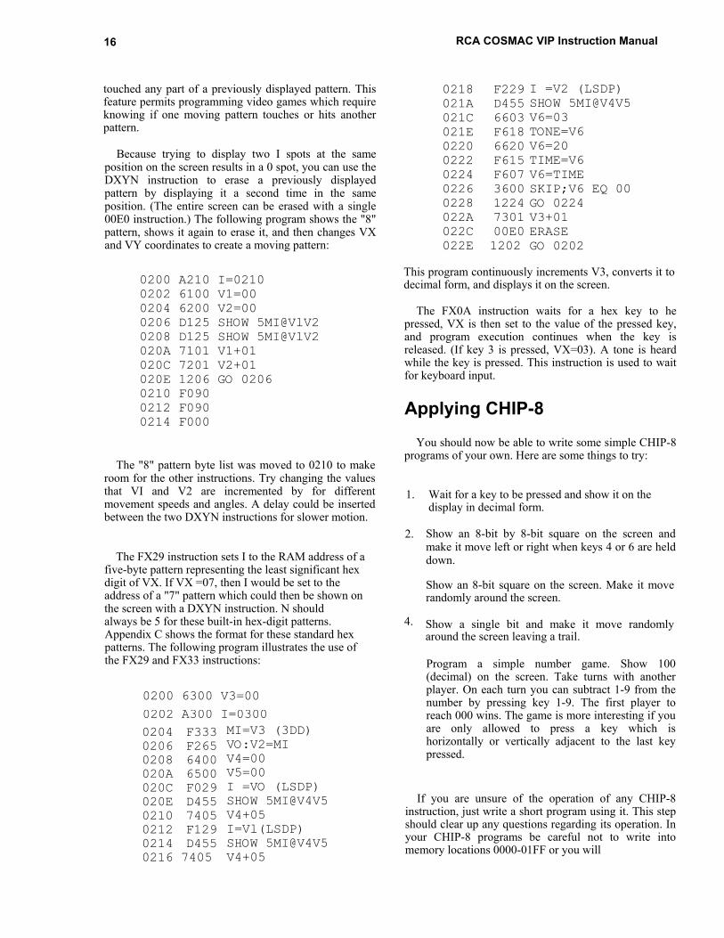
The FX29 instruction sets I to the RAM address of afive-byte pattern representing the least significant hexdigit of VX. If VX =07, then I would be set to theaddress of a "7" pattern which could then be shown onthe screen with a DXYN instruction. N shouldalways be 5 for these built-in hex-digit patterns. 4.Appendix C shows the format for these standard hexpatterns. The following program illustrates the use ofthe FX29 and FX33 instructions:
0200 6300 V3=000202 A300 I=03000204 F3330206 F2650208 6400020A 6500020C F029020E D4550210 74050212 F1290214 D4550216 7405
MI=V3 (3DD)VO:V2=MIV4=00V5=00I =VO (LSDP)SHOW 5MI@V4V5V4+05I=Vl(LSDP)SHOW 5MI@V4V5V4+05
Show an 8-bit by 8-bit square on the screen andmake it move left or right when keys 4 or 6 are helddown.
Show an 8-bit square on the screen. Make it moverandomly around the screen.
Show a single bit and make it move randomlyaround the screen leaving a trail.
Program a simple number game. Show 100(decimal) on the screen. Take turns with anotherplayer. On each turn you can subtract 1-9 from thenumber by pressing key 1-9. The first player toreach 000 wins. The game is more interesting if youare only allowed to press a key which ishorizontally or vertically adjacent to the last keypressed.
If you are unsure of the operation of any CHIP-8instruction, just write a short program using it. This stepshould clear up any questions regarding its operation. Inyour CHIP-8 programs be careful not to write intomemory locations 0000-01FF or you will

111. CHIP-8 Language Programming 17
lose the CHIP-8 interpreter and will have to reload it.You can insert stopping points in your program fordebugging purposes. Suppose you want to stop andexamine variables when your program reaches theinstruction at 0260. Just write a 1260 instruction atlocation 0260. Flip RUN down and use operating systemmode A to examine variables V0-VF. The memory mapin Appendix C shows where you can find them.
After the above practice you are ready to design moresophisticated CHIP-8 programs. Always prepare aflowchart before actually writing a program. The last352 bytes of on-card RAM are used for variables anddisplay refresh. In a 2048-byte RAM system you can uselocations 0200-069F for your programs. This area isenough for 592 CHIP-8 instructions (1184 bytes). In a4096-byte RAM system you can use locations0200-0E8F. This area is equal to 1608-CHIP-8instructions (3216 bytes).
Some Program IdeasHere are a few ideas for programs to write using the
CHIP-8 language:
1. INTOXICATION TESTER - Display a six digitrandom number on the screen for several seconds.You must remember this number and enter it fromthe keyboard within ten seconds after the screengoes blank to prove that you're sober and score.
2. NUMBER BASE QUIZ - Display numbers in 18.binary or octal on the screen. You must entertheir decimal equivalent to score points.
3. DICE - Push any key to simulate rolling dicedisplayed on the screen.
4. PUPPETS - Show large face on the screen. Letsmall children move mouth and roll eyes by 20.pushing keys.
r BUSY BOX - Let small children push keys to 21.make different object appear on the screen,move, and make sounds.
6. SHUFFLEBOARD - Simulate shuffleboardtype games on the screen.
7. COMPUTER ART - Design new programs togenerate pleasing geometric moving patterns onthe screen.
8. INVISIBLE MAZE - Try to move a spotthrough an invisible maze. Tones indicate whenyou bump into a wall.
9. LUNAR LANDING - Program a graphic lunarlanding game.
10. COLLIDE - Try to maneuver a spot from oneedge of the screen to the other without hittingrandomly moving obstacles.
Il. CAPTURE - Try to chase and catch randomlymoving spots within a specified time limit.
12. LEARNING EXPERIENCES - Program graphichand and eye coordination exercises for youngchildren or those with learning disabilities.
13. NUMBER RECOGNITION - Show groups ofobjects or spots on the screen. Young child mustpress key representing number of objects shownto score.
WALL BALL - Program a wall-ball-type paddlegame for one player.
15. FOOTBALL - Each player enters his play via thehex keyboard and the computer moves the ball onthe screen.
16. BLACKJACK - Play "21" against the computer dealer.
17. HOLIDAY DISPLAYS - Design custom,animated displays for birthdays, Halloween,Christmas, etc.
METRIC CONVERSION - Help children learnmetric by showing lengths on screen in inches andrequiring centimeter equivalent to be entered toscore.
19. TURING MACHINE - Simulate a simplifedTuring machine on the screen.
TIMER - Use the computer to time chess games,etc.
HEXAPAWN - Program Hexapawn so that thecomputer learns to play a perfect game.
22. NIM - Program Nim with groups of spotsshown on the screen.
23. BLOCK PUZZLES - You can simulate a varietyof sliding block-type puzzles on the screen.
24. BOMBS AWAY - Show a moving ship at thebottom of the screen. Try to hit the ship byreleasing bombs from a moving plane at the top ofthe screen.

18
25. PROGRAMMED SPOT - Introduce children toprogramming concepts by letting thempreprogram the movements of a spot or object onthe screen.
RCA COSMAC VIP Instruction Manual
The next section will discuss machine languageprogramming. You can even combine machine languagesubroutines with CHIP-8 programs if desired.

19
IV. Machine Language Programming
VIP Machine CodingFor a complete description of machine language
instructions, refer to the User Manual for the CDP1802COSMAC Microprocessor MPM201A. YourCOSMAC VIP computer incorporates the followingspecial machine-language input and output instructions:
CODE OPERATION
696B6162
6364
Turn display on (Bus -> MX,D)Input port byte + MX,D (Optional)Turn display off (MX -> Bus,RX+1)MX(LSD) -> Hex keyboard latch,
RX+1MX -> Output port, RX+1 (Optional)MX -> Bus,RX+l
One 64 instruction is always executed by theOperating System. It can also be used in expandedsystems if desired. Instructions 65, 66, 67, 6A, 6C, 6D,6E, and 6F are also available for use in expandedsystems.
The External Flag lines are used as follows:
FLAG
EF1
EF2EF3EF4
USE
Generated by the video interface(CDPI861)
Serial data from cassette playerHex key pressed signalNot used in basic system
EF4 can be used for system expansion. EF3 can alsobe used in expanded systems if no key will be depressedat the same time that an external device is using EF3.EF1 can only be used by an external device when thedisplay is turned off. EF2 should not be used inexpanded systems.
The latched Q line output performs several functionsin the COSMAC VIP system. When set, it holds the Qlight on and generates a continuous speaker tone. Ile Qline is also used for serial output data to a cassetterecorder. You can use the Q output line as a controlsignal in an expanded system if you avoid conflicts withits normal functions.
You can store a machine language program starting atlocation 0000. It will be executed when you flip theRUN switch up. Initially P=0, X=0, R0=0000, Q=0, andR1=0XFF, where 0X= last page of on-card RAM. (0X =07 in 2048-byte RAM system). The operating systemuses the last 84 bytes of on-card RAM. You shouldavoid using these last 84 RAM bytes when writingmachine language programs. With a 2048-byte RAM,locations 07AC-07FF would be reserved for use by theoperating system. Note that Rl initially contains theaddress of the last on-card RAM byte. Your machinelanguage program can use Rl to determine the amount ofRAM in your system when required.
Putting Machine Coding andCHIP-8 Language Together
The operating system and the CHIP-8 languageinterpreter use a video display format that is 64 bits wideby 32 bits high. This 256-byte display can easily bemodified by writing your own video refresh interruptroutine as explained in the CDP1861 data sheet providedin Appendix G. Display formats up to 64 bits wide by128 bits high are possible with no hardwaremodification. The 4096-bit picture program in AppendixD uses a machine language refresh interrupt routine thatprovides a format 64 bits wide by 64 bits high.

20
The CHIP-8 language described in the previoussection, permits machine language subroutines to becalled with a 0MMM instruction. A D4 machinelanguage instruction at the end of the machine languagesubroutine returns control to the CHIP-8 instructionfollowing the 0MMM instruction. In Appendix C, theCDP1802 register use for the CHIP8 language isprovided. R5 is used as the CHIP-8 program counter.When you call a machine language subroutine with a0MMM instruction, R5 will be addressing the CHIP-8instruction following the 0MMM. The machine languagesubroutine could retrieve the next two CHIP-8 programbytes as parameters by addressing with R5 andincrementing it by 2 before returning control to theCHIP-8 program with a D4 instruction. RC, RD, RE, andRF are available for use in machine languagesubroutines. RA is the CHIP-8 memory pointer (1).Changing the high-order byte of RB will cause anydesired RAM page to be displayed. R3 is the machinelanguage subroutine program counter.
CHIP-8 uses the operating system refresh interruptroutine contained in ROM for display. You can use thisROM interrupt routine for 256-byte display in your ownmachine language programs. First initialize R1 to 8146and R2 as a stack pointer before turning on the videointerface with a 69 instruction. Set the desired displaypage into RB.1. This interrupt routine uses R0 as thedisplay refresh pointer and modifies RB.0. R8.1 andR8.0 are decremented by 1 during each interrupt unlessthey are equal to 00. Interrupts occur 60 times per secondwhen the video interface is turned on. This rate iscontrolled by a crystal clock so that R8.0 and R8.1 canbe used as real-time clocks when needed. -
RCA COSMAC VIP Instruction Manual
While the video interface is turned on, you should notuse any of the 3-machine-cycle CDP1802 instructions(except those used for sync in the refresh interruptroutine itself). If you are not using the video interface,then you can use the CDP1802 3-cycle instructions inyour machine language programs. When you initiate amachine language program at 0000 by flipping RUN up,the video interface will be off. You must turn it on with a69 instruction to use the COSMAC VIP graphic displaycapability.
Machine LanguageProgramming Summed Up
In summary, COSMAC VIP provides you with aneasy-to-use language called CHIP-8. You can insertmachine language subroutines in CHIP-8 programs forgreater flexibility or expanded I/0 capability. You canwrite complete machine language programs to fullyutilize CDP1802 capabilities. The operating svstemfacilitates debugging machine language programs bypermitting you to examine general registers R3-RF. (Seeoperating system register table in Appendix B).Advanced programmers can even develop their own,interpretive language tailored to special requirements.Direct execution of machine language code starting atlocation 0000 together with the expansion interfacepermits the COSMAC VIP system to be used as alow-cost development system as well as a personalrecreational or educational computer.

21
V. Logic Description
A complete set of logic diagrams is provided inAppendix E. Power requirements for a system with 2048bytes of RAM is 5 V DC at 350 mA. If you wish toexpand the system you can use your own higher currentpower supply.
This system is designed around the CDP1802microprocessor Wfl. Refer to the CDP1802 data sheetand User Manual for the CDPI802 COSMACMicroprocessor MPM-201A for a complete descriptionof its operation. The CDP1802 requires a square-waveclock input at pin 1 for operation. This system uses a1.7609-MHz clock. One half of U3 is connected as afree-running crystal-controlled oscillator. A3.52180-MHz crystal is used in this circuit. The output ofthis 3.52180-MHz oscillator is then divided by 2 usingU4 to provide the 1.7609MHz input clock for theCDP1802. Because each CDP1802 machine cycle equals8 clock cycles, each machine cycle is about 4.54 us induration. TPA and TPB are timing pulses generated onceeach machine cycle by the CDP 1802 microprocessor.
How Memory Is AddressedA debounced RUN level goes high when the RUN
switch is flipped up. This signal causes the CDP1802 tobegin fetching instructions from memory. When theRUN switch is down, the CDP1802 is held in a resetstate and U6A (in Fig. E-2) is reset. U6B is held set byU6A. The CDP1802 starts fetching instructions from theROM (U10) at location 8000 since UOB is being heldset. The ROM contains the
operating system program which uses a 64 instruction togenerate an N2 pulse. This-N2 pulse sets U6A so it nolonger holds U6B in its set state. From this point on, theselection,of RAM or ROM locations is controlled by themost significant address bit latched into U6B each cycleby TPA.
U8 latches an additional 4 address bits to provide the1-9-bit address required in a 4096-byte RAM system.U9A decodes 2 of these address bits into 4 lines whichare used to select up to four 1024-byte RAM sections.Each 1024-byte section of RAM consists of two 4 x1024-bit RAM IC's (U16-U23 in Fig. E-4). Only the firsttwo sections of RAM (U16-U19) are used in a 2048-bytesystem. U9B in Fig. E-2 is wired as a simple gate thatinhibits selecting any section of RAM when either theROM is selected or a positive RAM inhibit signal isgenerated on pin 19 of the expansion interface byexternal circuits.
Memory read (MRD) and write (MWR) signals aresupplied to the RAM at appropriate times by theCDP1802. Data is transferred between memory,CDP1802, input, or output via an 8-bit data bus. Pull-upresistors are provided on this bus for compatibility withTTL signal swings provided by some RAMs.
How the Input/Output WorksUll and U12 in Fig. E-3 are used to decode the
input/output instruction codes used in the system.
U13 provides the hex keyboard interface. Thisinterface permits a program to determine which key is

pressed. A 62 machine instruction causes the leastsignificant 4 bits of memory byte to be latched into U13.These 4 bits are decoded to bring one of the 16 U13output lines low. If the key that corresponds to thisoutput line is pressed, the CDPI802 EF3 input will golow. The 4-bit codes latched into U13 correspond to theequivalent key positions. After the program send8 a 4-bitcode to U13, it subsequently examines the EF3 line tosee if the key corresponding to this code is pressed ornot. In this manner, a program can determine when anyspecific key is pressed or can sequentially scan all keyswhile waiting for any one to be pressed. Key debouncedelays must be provided in the program when required.A program can also cause a speaker tone to occur when akey is pressed. Only one key at a time should be pressedwith this method of interfacing the keyboard.
U15 generates an audible tone when pin 4 is high. Theoutput on pin 3 drives a small speaker. The 10 ohmresistor R48 in series with the speaker output can beraised in value to lower the volume if desired. TheCDP1802 latched Q-line output drives the tone generatorand also turns on the Q light. Q can be set high (1) or low(0) by machine language instructions. The RC networkconnected to pins 2, 6, and 7 of U15 determines thefrequency of the tone. You can increase or decrease thevalue of R to adjust this frequency to suit your taste.
Q is also shaped by U14A in Fig. E-3 to form a signalsuitable for recording on an audio cassette. Audiocassette recorders can't cope with square waves. Tledivider on the output of U 14A reduces the signal toabout 50 mV which is suitable for the microphone inputof most recorders. During recording, the operatingsystem program in ROM converts memory bytes into bitserial form and transmits them to the recorder via the Qline. See the cassette data test page of Appendix A forthe cassette data code used.
In playback, bit serial data from the cassette drives thetape light. The serial data is amplified and shaped
RCA COSMAC VIP Instruction Manual
into 5-volt pulses by U14B. The output of U14B isconnected to the CDP1802 EF2 input line. The operatingsystem reads tape data by examining the timing of thetransitions on the EF2 input line. Cassette read andrecord timing is derived from the crystal-controlled clockso that no adjustments are necessary.
Video output is provided by the unique CDP1861video display interface IC (U2 in Fig. E-1). Refer to theCDP1861 data sheet. in Appendix G for a description ofits operation. This chip provides one of the lowest costand most useful display interface capabilities availablefor any microcomputer. The values of the resistors RIand R4 in Fig. E-1 of Appendix E connected to outputpins 6 and 7 of U2 can be adjusted for best results withyour video display. 61 and 69 machine languageinstructions are used to generate the required on and offpulses for U2. The down position of the RUN switchresets the internal U2 circuits. When a program isinitiated, by flipping RUN up, U2 will remain off until a69 instruction is executed. No CDP1802 interrupt orDMA requests are generated by U2 until it is turned onby a 69 instruction. U I and U2 are both driven by thesame clock. They must remain in sync to provide properoperation of the display.
In general, the logic of this system has been keptsimple and straight-forward by the use of software toreplace hardware. This design not only yields a low costsystem, but one that should prove extremely reliablebecause of the reduced number of components that cancause failures. This system will not become obsolete fora long time. RAM, ROM, and microprocessor are allstate-of-the-art devices and not obsolescent types that areabout to be replaced by better ones. The cassette andvideo interfaces are optimum for long life. Also designedinto the system are full expansion capability for addedRAM, ROM, input, output, and full color graphics.

V1. Expansion Considerations andConnections
The COSMAC VIP was designed primarily as aself-contained graphic system for home use. EnoughRAM and input/output features are provided for years ofcomputer fun without adding anything to your system. If,however, you do want to expand your system, a varietyof features have been included to make expansion aseasy and inexpensive as possible. You can easilyincrease RAM to 4096 bytes by adding U20-U23to your PC card. Use the same type or a compatible typeof RAM as used for U16-U19. You may, however,have to add a higher-current power supply whenexpanding RAM.
Using the ByteInput/Output
First, you may wish to add some external com-puter-controlled devices such as relays, input sensingswitches, or even a low-cost printer. The printer willrequire an 8-bit parallel input or output port and some"hand-shaking" signals. One parallel input port and oneparallel output port are available on the PC card asshown in Fig. E-5 in Appendix E. These ports areprovided by U24, U25, U26, and U27 along withthe associated resistors and two IN914 diodes. The 22input/output port connection pads (A-Z) along theback right edge of the PC card are connected to astandard 44-pin card socket on the COSMAC VIP board.You can plug your external circuits or devices into thissocket. Table II gives the input/output port terminalconnections.
The 8 buffered output signals(M,N,P,R,S,T,U,V) will each drive up to 2TTL loads. A 63 machine language instruction willlatch a memory byte into U24 for output. The 8 latchedoutput lines can be used to drive individual relay drivercircuits, power amplifiers, lights, battery motor drivers,etc. The
23
buffered Q output line (W) can be used as an outputstrobe for transferring the latched output byte to anexternal device such as a printer. The EF3 (X) and EF4(L) input fines can be used to indicate the status of anexternal device. Don't forget that EF3 is shared with thehex keyboard.
Table 11 - Input/Output Port Terminal Connections(See Fig. E-5, Appendix E)
Pin Signal Description
24
A single photocell input could be provided via thebuffered EF4 line. You can attach the photocelldirectly between the L and Z pads. Experimentallyadjust the pull-up resistor on pad L for bestoperation. No photocell amplifier should be requiredto drive the COS/MOS input. An, externally suppliedpositive pulse- on. Pins 2_and 14 of U25,can be used asan input,byte- strobe when yow want to latch an inputbyte into U25. A 68 can be used to storethis input byte in RAM.
Using the ExpansionInterface
The 44-pin card socket for the expansion interfacepads along the back left edge of the PC board permitsextensive expansion. If you expand beyond thecapabilities of the power converter provided with theVIP, you will, of course, have to provide your own powersupply. Output signals should only drive COS/MOSloads, and must be externally buffered with a. CD4050or CD4049 IC to drive TTL loads. Keep any wiresconnected to the expansion pad signals as short aspossible. Excessive stray capacitance on these signallines can interfere with proper operation of the computer.Input signals should also be buffered with COS/MOScircuits. Refer to the. machine language programmingsection (Section IV) and the logic diagrams (Appendix E)to avoid conflicts with normal COSMAC VIP use ofthese signals. The external option terminal connectionsare given in Table III.
You can latch up the required high order address bitswith the trailing edge of TPA when adding externalmemory. You must provide a Positive level on pad 19 todisable internal RAM when external RAM is addressed.The operating system will always use the highest page ofinternal (on-card) RAM, even when you add externalRAM.
If you wish to substitute an external ROM orbattery-powered COS/MOS RAM for U10, you can usethe signal on pad X to select it. Remove U10 whensubstituting an external ROM. If you do use an externalROM for your own operating system you may no longerbe able to use the CHIP-8 interpreter because it requiressome of the operating system subroutines.
The expansion interface pads provide access to allCDP1802 signals so that you can add any desiredexternal circuits.
Only 5 out of the possible 14 CDP1802 input/outputinstructions are used internally, so that you can externallydecode the N0, N1, and N2 lines and use them with MRDto obtain the use of the remaining 9 input/outputinstruction codes. You can
I RCA COSMAC VIP Instruction Manual
also latch high-order address bits to select externaldevices if desired. When using external circuits togenerate DMA requests, interrupt requests, or input flagsignals, isolate these signals with 1N914 diodes as shownfor EF3 and EF4 in the optional parallel input/ outputport logic. Refer to the User Manual for the CDPI802COSMAC Microprocessor, MPM-201A, for specificexamples of input/output attachment techniques.
Some Expansion IdeasThe August and September 1976 issues of Popular
Electronics contain descriptions of a COSMAC ELFmicrocomputer using the CDP1802. These articlesillustrate some input/output attachment techniques.
The following lists some things that with someexercise of your ingenuity could be added to your systemat relatively low cost:
1. Manually operated photoelectric paper-tape stripreader. Only requires a tape guide and 8photocells.
2. Scanning circuit for multiple input lines fromsensing devices using CD4515 IC.
3. Full alphanumeric keyboard.
4. Low-cost printer.
5. Multi-digit numeric display.
6. Calculator chip.
7. Individual photocells or switches.
8. Output relays to control solenoids, bells,whistles, sirens, lights, or motors.
9. Sound-generating circuits that can be controlledby program.
10. Analog-to-digital input circuits.
11. Read-Only Memory for fixed program.
12. Digital-to-analog output circuits.
13. Alpha wave monitor input to control pictures onTV or output devices.
14. Temperature- or pressure-sensing devices.
15.
16.
Computer terminal.
A second hex keyboard for multi-player videogames.

I
Pin Signal Description
Negative-going memory-write pulse Earlytiming pulse for M address clocking, etc.
Memory address lines. High-order address byteappears on these lines during TPA time.,followed by low-order address byte
8-bit, 2-way tri-state data bus
Low for memory read machine cyclesChip select for operating systemOptional power for external logic
CDP1802 clock outputFlag input lines #3 and #4(Flag 3 also used for hex keyboard)Crystal frequencyFlag input line #1Low-order 3 bits of N during6N instruction
Video spot outputVideo sync outputTiming pulse for clocking memory byte out, etc.State code bit (+5 V for SI /S3, GND for SO/S2)Pulling to GND causes interrupt (22-KE2 input)State code bit (+5 V for S2/S3, GND for SO/Sl)Pull to GND for DMA-OUT cyclesQ flip-flop output linePull to GND for DMA-IN cycles+5 V when running, GND when RUN switch downInternal RAM-disable inputGND when RAM pages C, D, E, and F selectedOptional power for external logic (same as Y-Z)
Table III - External Option Terminal Connections(See Fig. E-2, Appendix E)
V1. Expansion Considerations and Connections .25

26
Some possible applications for expanded systemsinclude:
1. Counting packages, parts, cars, or people via 9.photocell or switch input.
2. Composing poetry or pictures with printer output.
3. Video target games using photocell light gun.
4. Monitor burglar alarm switches.
5. Monitor water level and temperature in fishtank and regulate automatically.
6. Measure motor speed with photocell.
7. Monitor and control experiments in home, school, or lab. Use video display for real time bar graphs of multiple variables.
RCA COSMAC VIP Instruction Manual
8. Provide a crystal-controlled, programmablepulse generator, clock, or timer.
Provide a programmable sequencer for lightshows, advertising displays, holiday lighting, etc.
10. Automatic telephone dialer.
11. Model railroad controller.
12. Battery-operated toy or robot controller.
13. Detect tape-player tones and control slideprojector.
You will soon discover that the potential applicationsof a computer such as the COSMAC VIP are onlylimited by your imagination and the ability to developappropriate interface circuits.

VIL Troubleshooting Hints
This section is aimed at helping you diagnose and fixhardware problems should they occur. First, check allIC's to make sure they are properly inserted in the PCcard. An IC inserted in the wrong direction can bepermanently damaged. Check that the +5 V DC supplyvoltage ripple does not exceed 0.2 volt. Visually inspectthe PC card for solder shorts or bad solder joints. Try toavoid zapping your PC card with static electricitycharges. Discharge youself, if necessary, by touching agrounded object before touching any IC's or PC cardwiring.
No SoundIf everything works but you don't hear any sound
from the speaker you probably have a bad U15, badspeaker, or bad connection. Flip RUN up with key Cdown. Hold any key down and the Q light should comeon. Check the Q line if it doesn't. The Q line should be at+5 V with a key held. If the Q light is on, but with notone, check U15 and your speaker connections.
No DisplayIf you get no display but do get operating system key
tones, check the video output signal. First, select theoperating system to make sure video should be present.The video signal should be 0.5 volt peak to peak orhigher. You should see negative-going vertical andhorizontal sync pulses and positive-going video pulses.The sync pulses should be about 25% of the total swing.Check your display system and interconnections if youhave the video signal present. Make sure you are usingthe correct high-impedance input setting, for example.
Other Problems
27
Using operating system mode 0, load bytes into RAMusing all 16 hex keys. If a key doesn't work or shows thewrong value on the display screen, check the keyboardand U13.
If everything except the cassette interface works,check U14. Review the cassette recording guidelines inAppendix A. Use the cassette phase and data testprocedures described in Appendix A to find out what'swrong.
If you can run some programs but not others, youmay have a bad RAM bit. Load and use the memory testprogram provided in Appendix A. Try changing RAMchips, one at a time.
If nothing seems to work and you can't run theoperating system, check your power supply and PC cardwiring for shorts again. If everything still seems OK youwill have to start signal tracing.
Signal TracingCheck the U3 oscillator output. If not present, replace
U3. If the 3.521280-MHz signal is present, check the U4divider. Replace U4 if it isn't toggling. Make sure youuse a 7474 type. With RUN up, you should see TPA andTPB pulses being generated at pins 33 and 34 of U1 Ifthey are not present, check the RUN level to make surethe switch is working, then replace U1.
Check the output of U6B to make sure that the ROMis initially selected when RUN is first flipped

28
up with key C down. With RUN up, check bus andaddress lines to see if any look different from the others.They will, of course, be at different levels or bouncingaround but you might spot something suspicious thatwould indicate a short or open for one of these lines.
Try operating with only a 1024-byte RAM (U16 andU17). Try the other two RAM chips in these sockets.Check U5 inputs and outputs to verify that all stages areinverting properly.
If you don't get a pulse at pin 10 of U2 when you flipRUN up with key C down, U12 may he bad. This pulseis a difficult pulse to see and you might have tobreadboard a latch or use a latching logic probe to catchit. If you get the display on pulse at pin 10 of U2, youshould then see U2 output pulses on pins 2, 3, and 9. Ifyou don't, try replacing U2.
RCA COSMAC VIP Instruction Manual
Last ResortsAs a last resort, try replacing Ul and the ROM. Check
the supply voltage at all chips. Examine the PC card forhairline breaks in the printed conductors. Fill upplated-through holes with solder to insure continuity.Check all signals. They should swing between groundand +4 or 5 volts. If you see a logic signal at someintermediate voltage, like +1 or 2 volts, check the sourceIC.
Once you get the operating system running, over 90%of the hardware will be operating properly. There are nocritical adjustments to be made or maintained. All systemtiming is controlled by the crystal clock. With reasonablecare your COSMAC VIP system should run for yearswithout any problems.

29
Appendix A - Test and Operating Data
Byte Pattern for Displaying "COSMAC"
The following figure shows how the word "COSMAC" would be formed by spots (or bits) on thedisplay screen.
The following bytes when loaded into memory will cause the word "COSMAC" to be shown onthe display in a 2048-byte RAM system. Start pattern of bytes at location OFOO in a 4096-bytesystem.
0700 F9 F3 E6 CF 9F 00 00 000708 81 12 07 C8 90 00 00 000710 81 13 E5 4F 90 00 00 000718 81 10 24 48 90 00 00 000720 F9 F3 E4 48 9F 00 00 000728 00 00 00 00 00 00 00 00
Beeper Program
This machine- language program flashes the Q light and beeps at a rate determined by the byte atlocation 0002. Change this byte for faster or slower rates.
0000 7A F8 0F BF 2F 9F 3A 040008 31 00 7B 30 01 00 00 00

30
Cassette Attachment Diagram
RCA COSMAC VIP Instruction Manual
Cassette Phase Test
For best results your cassette recorder should notreverse the phase of an input signal on playback. Whenplaying back a tape recorded on another recorder, itshould not reverse the phase of the output signal. Youmay have to reverse the internal head connections onsome cassette recorders to eliminate unwanted phasereversals.
To check for phase reversals, load the machinelanguage test program, given below, into memory.
Run this program to generate a phase test signal on thetape out line. Record one minute of this test signal, thenplay it back and observe the cassette recorder output on ascope. It should appear as shown in B or C below. Savethis tape to test new recorders on which you want to playtapes you have recorded on a previously tested machine.If the playback signal appears upside down from thatshown in B or C, you will have to reverse the internalhead connection leads on the out-of-phase recorder.
Test Program
0000 F8 04 AA 7B F8 0C FF 010008 3A 06 7A F8 0C FF 01 3A0010 0D 2A 8A 3A 03 F8 60 FF0018 01 3A 17 30 00 00 00 00
Signals
Appendix A - Test and Operating Data
Cassette Data Test
Load the following machine language program into memory:
0000 90 B6 B3 F8 33 A6 F8 OA0008 A3 D3 F8 6F AC F8 40 B90010 93 F6 DC 29 99 3A 10 F80018 10 A7 F8 08 A9 06 B7 F80020 80 FE DC 97 F6 B7 DC 290028 89 3A 23 17 87 F6 DC 300030 17 30 31 35 00 00 00 00
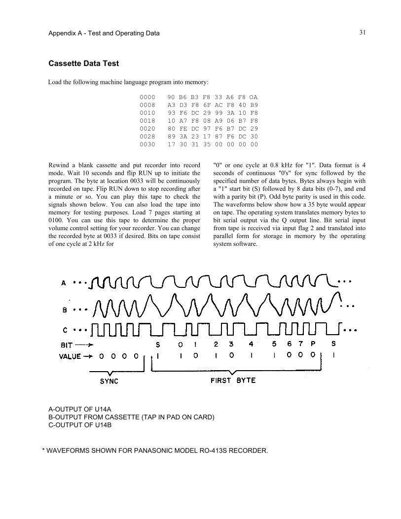
Rewind a blank cassette and put recorder into recordmode. Wait 10 seconds and flip RUN up to initiate theprogram. The byte at location 0033 will be continuouslyrecorded on tape. Flip RUN down to stop recording aftera minute or so. You can play this tape to check thesignals shown below. You can also load the tape intomemory for testing purposes. Load 7 pages starting at0100. You can use this tape to determine the propervolume control setting for your recorder. You can changethe recorded byte at 0033 if desired. Bits on tape consistof one cycle at 2 kHz for
31
"0" or one cycle at 0.8 kHz for "1". Data format is 4seconds of continuous "0's" for sync followed by thespecified number of data bytes. Bytes always begin witha "1" start bit (S) followed by 8 data bits (0-7), and endwith a parity bit (P). Odd byte parity is used in this code.The waveforms below show how a 35 byte would appearon tape. The operating system translates memory bytes tobit serial output via the Q output line. Bit serial inputfrom tape is received via input flag 2 and translated intoparallel form for storage in memory by the operatingsystem software.
A-OUTPUT OF U14AB-OUTPUT FROM CASSETTE (TAP IN PAD ON CARD)C-OUTPUT OF U14B
* WAVEFORMS SHOWN FOR PANASONIC MODEL RO-413S RECORDER.

0000 90 B1 B2 B3 F8 17 A3 D30008 42 70 22 78 22 52 C4 C40010 C4 94 80 91 AO 30 08 F80018 0A Al F8 7F A2 E2 69 F80020 04 B4 F8 00 A4 94 B7 840028 A7 7A E2 F8 00 A5 F8 FF0030 A6 85 57 94 BA 84 AA 8A0038 52 87 F3 3A 45 9A 52 970040 F3 3A 45 30 47 86 5A 1A0048 9A 52 94 FC 04 F3 3A 370050 07 52 85 F3 3A 6C F8 FF0058 A5 93 A6 31 60 7B 30 310060 17 97 52 94 FC 04 F3 3A0068 29 7A 30 6A 7B 30 6D 000070 00 00 00 00 00 00 00 000078 00 00 00 00 00 00 00 00
32 RCA COSMAC VIP Instruction Manual
Cassette Recording Guidelines
1. Use high quality tape (Maxell UD or 19.equivalent).
2. Use shortest tapes possible. You can shortentapes to several minutes in length if you enjoy 20.splicing.
3. Keep heads and pinch rollers clean.
4. Keep heads aligned for tape interchangeability.
5. Avoid recording too close to beginning of tape.
6. Make sure cassette is properly seated in 22.recorder.
7 If you have trouble with a cassette try others.You can have a had spot on tape or a warpedcassette.
8. Highest setting of tone control is usually best.
9. Set recorder volume control so that TAPE lightglows steadily on playback. This setting shouldbe lower than highest-volume setting. ExcessiveTAPE light flickering indicates a bad tape ormisaligned heads.
10. A dirty recorder volume control can cause tapedropouts.
11. Make sure cassette connection plugs make goodcontact.
12. Rewind cassettes before removing them fromrecorder.
14. Avoid exposing cassettes to heat or magneticfields.
13. Store cassettes in dust-proof containers.
15. Before recording, wind cassette to one end andfully rewind.
16. Cassette recorders will give you problems once ina while (they don't like certain cassettes, etc.). Ifone gives you problems most of the time replaceit.
17. Make sure that MIKE plug is connected beforerecording. You will hear a tone even if MIKE plugis out. On most recorders the TAPE light willglow while recording.
18. When recording give the page key a short tap tostart.
Use the last byte of a tape block as a programidentification and check code. It will appear on thedisplay screen after the tape is loaded.
When loading a cassette into memory, the tapemust contain as many pages as you specify to beloaded. If you try to load 8 pages from a 7-pagetape the loading operation won't terminateproperly.
21. You may have to record with the EAR plug outfor some tape recorders.
Always use AC adaptor with recorder for bestresults.
Memory Test Program
This machine language program should be loaded into0000-007F. It checks RAM locations 0000-07FF (UI8and U19) for proper data storage. Flip RUN up to starttest. Beeps sound during test. Entire 1024 byte sectionof RAM being tested is shown on screen. Program stopswith tone on if a bad RAM bit is found. Error byte is at007F. This byte should be 00 or FF for no error. Forexample, if byte is 01 or FE then bit 0 was bad. Theerror byte is also shown on the screen.
Set location 0020=00 and location 0023=80 to testRAM locations 0080-03FF (U16 and U17).

33
Appendix B - Operating System
Operating System ListingThe following shows the machine language code for
the ROM operating system. ROM is addressed at8000-81FF. This listing can be used to verify thecontents of the ROM if required.
8000 F8 80 B2 F8 08 A2 E2 D28008 64 00 62 0C F8 FF Al F88010 0F B1 F8 AA 51 01 FB AA8018 32 22 91 FF 04 3B 22 B18020 30 12 36 28 90 A0 E0 D08028 El F8 00 73 81 FB AF 3A8030 29 F8 D2 73 F8 9F 51 818038 A0 91 B0 F8 CF Al D0 738040 20 20 40 FF 01 20 50 FB8048 82 3A 3E 92 B3 F8 51 A38050 D3 90 B2 BB BD F8 81 BI8058 B4 B5 B7 BA BC F8 46 Al8060 F8 AF A2 F8 DD A4 F8 C68068 A5 F8 BA A7 F8 Al AC E28070 69 DC D7 D7 D7 B6 D7 D78078 D7 A6 D4 DC BE 32 F4 FB8080 0A 32 EF DC AE 22 61 9E8088 FB 0B 32 C2 9E FB 0F 3A8090 8F F8 6F AC F8 40 B9 938098 F6 DC 29 99 3A 97 F8 1080A0 A7 F8 08 A9 46 B7 93 FE80A8 DC 86 3A AD 2E 97 F6 B780B0 DC 29 89 3A AD 17 87 F680B8 DC BE 3A 9E DC 69 26 D480C0 30 C0 F8 83 AC F8 0A B980C8 DC 33 C5 29 99 3A C8 DC80D0 3B CF F8 09 A9 A7 97 7680D8 B7 29 DC 89 3A D6 87 F680E0 33 E3 7B 97 56 16 86 3A80E8 CF 2E BE 3A CF 30 BD DC80F0 16 D4 30 EF D7 D7 D7 5680F8 D4 16 30 F4 00 00 00 00<eom>
8100 30 39 22 2A 3E 20 24 348108 26 28 2E 18 14 1C 10 128110 F0 80 F0 80 F0 80 80 808118 F0 50 70 50 F0 50 50 508120 F0 80 F0 10 F0 80 F0 908128 F0 90 F0 10 F0 10 F0 908130 F0 90 90 90 F0 10 10 108138 10 60 20 20 20 70 A0 A08140 F0 20 20 7A 42 70 22 788148 22 52 C4 19 F8 00 A0 9B8150 B0 E2 E2 80 E2 E2 20 A08158 E2 20 A0 E2 20 A0 3C 538160 98 32 67 AB 2B 8B B8 888168 32 43 7B 28 30 44 D3 F88170 0A 3B 76 F8 20 17 7B BF8178 FF 01 3A 78 39 6E 7A 9F8180 30 78 D3 F8 10 3D 85 3D8188 8F FF 01 3A 87 17 9C FE8190 35 90 30 82 D3 E2 9C AF8198 2F 22 8F 52 62 E2 E2 3E81A0 98 F8 04 A8 88 3A A4 F881A8 04 A8 36 A7 88 31 AA 8F81B0 FA 0F 52 30 94 00 00 0081B8 00 D3 DC FE FE FE FE AE81C0 DC BE F1 30 B9 D4 AA 0A81C8 AA F8 05 AF 4A 5D 8D FC81D0 08 AD 2F 8F 3A CC 8D FC81D8 D9 AD 30 C5 D3 22 06 7381E0 86 73 96 52 F8 06 AE F881E8 D8 AD 02 F6 F6 F6 F6 D581F0 42 FA 0F D5 BE F6 AE 3281F8 DC 3B EA 1D 1D 30 EA 01<eom>

34
Operating System Register Table
RCA COSMAC VIP Instruction Manual
Memory Register Memory RegisterAddress Byte Address Byte,0XB0 0XC00XB1 0XC10XB2 0XC20XB3 R3.0 0XC3 R3.10XB4 R4.0 0XC4 R4.10XB5 R5.0 0XC5 R5.10XB6 R6.0 0XC6 R6.10XB7 R7.0 0XC7 R7.10XB8 R&0 0XC8 R8.10XB9 R9.0 0XC9 R9.10XBA RA.0 0XCA RA.10XBB RB.0 0XCB RB.10XBC RC.0 0XCC RC.10XBD RD.0 0XCD RD.10XBE RE.0 0XCE RE.10XBF RF.0 0XCF RF.1
0X = 07 for 2048-byte RAM0X = 0B for 3072-byte RAM0X = 0F for 4096-byte RAMR5 = CHIP-8 language program counterRA = CHIP-8 language I pointerR3 = Machine Language Subroutine Program Counter
Operating System Summary1. RUN up with key C pressed selects operating
system at 8000.
2. Enter four-digit address followed by mode digit: 5.
A MR (Memory Read)0 MW (Memory Write)B TR (Tape Read)F TW (Tape Write)
3. CDP1802 microprocessor registers are stored asshown in table above. They may be examined aftera program is run by using operating system mode A.
4. Mode 0 can be used to insert temporary stops in aprogram for debugging purposes. Insert a"branch-to-itself" instruction at the desired stoppingpoint.
The operating system uses the top 84 bytes of RAM(0XAC-0XFF). Avoid using these byte locations inyour programs.
6. The operating system searches for and uses the top(highest) 256-byte page of on-card RAM. WhenRUN is flipped up to execute a program, beginningat 0000, the following initial conditions exist:
P=0, Q=0, R0=0000, and R1 =0XFF where 0X highestpage of on-card RAM.

Appendix C - CHIP-8 Interpreter
CHIP-8 Interpreter Listing
35
To use the CHIP-8 language you must first load thefollowing interpreter program into memory
locations 0000-0IFF (2 pages). This interpreter willallow you to run the games in Appendix D or write yourown programs using the CHIP-8 instruction setdescribed in section III.
0100 00 00 00 00 00 45 A3 980108 56 D4 F8 81 BC F8 95 AC0110 22 DC 12 56 D4 06 B8 D40118 06 A8 D4 64 0A 01 E6 8A0120 F4 AA 3B 28 9A FC 01 BA0128 D4 F8 81 BA 06 FA 0F AA0130 0A AA D4 E6 06 BF 93 BE0138 F8 1B AE 2A 1A F8 00 5A0140 0E F5 3B 48 56 0A FC 010148 5A 30 40 4E F6 3B 3C 9F0150 56 2A 2A D4 00 22 86 520158 F8 F0 A7 07 5A 87 F3 170160 1A 3A 5B 12 D4 22 86 520168 F8 F0 A7 0A 57 87 F3 170170 1A 3A 6B 12 D4 15 85 220178 73 95 52 25 45 A5 86 FA0180 0F B5 D4 45 E6 F3 3A 820188 15 15 D4 45 E6 F3 3A 880190 D4 45 07 30 8C 45 07 300198 84 E6 62 26 45 A3 36 8801A0 D4 3E 88 D4 F8 F0 A7 E70lA8 45 F4 A5 86 FA 0F 3B B201B0 FC 01 B5 D4 45 56 D4 4501B8 E6 F4 56 D4 45 FA 0F 3A01C0 C4 07 56 D4 AF 22 F8 D301C8 73 8F F9 F0 52 E6 07 D201D0 56 F8 FF A6 F8 00 7E 560lD8 D4 19 89 AE 93 BE 99 EE01E0 F4 56 76 E6 F4 B9 56 4501E8 F2 56 D4 45 AA 86 FA 0F01F0 BA D4 00 00 00 00 00 0001F8 00 00 00 00 00 E0 00 4B<eom>
0000 91 BB FF 01 B2 B6 F8 CF0008 A2 F8 81 B1 F8 46 Al 900010 B4 F8 1B A4 F8 01 B5 F80018 FC A5 D4 96 B7 E2 94 BC0020 45 AF F6 F6 F6 F6 32 440028 F9 50 AC 8F FA 0F F9 F00030 A6 05 F6 F6 F6 F6 F9 F00038 A7 4C B3 8C FC 0F AC 0C0040 A3 D3 30 1B 8F FA 0F B30048 45 30 40 22 69 12 D4 000050 00 01 01 01 01 01 01 010058 01 01 01 01 01 00 01 010060 00 7C 75 83 88 95 B4 870068 BC 91 EB A4 D9 70 99 050070 06 FA 07 BE 06 FA 3F F60078 F6 F6 22 52 07 FA 1F FE0080 FE FE F1 AC 9B BC 45 FA0088 0F AD A7 F8 D0 A6 93 AF0090 87 32 F3 27 4A BD 9E AE0098 8E 32 A4 9D F6 BD 8F 7600A0 AF 2E 30 98 9D 56 16 8F00A8 56 16 30 8E 00 EC F8 D000B0 A6 93 A7 8D 32 D9 06 F200B8 2D 32 BE F8 01 A7 46 F300C0 5C 02 FB 07 32 D2 1C 0600C8 F2 32 CE F8 01 A7 06 F300D0 5C 2C 16 8C FC 08 AC 3B00D8 B3 F8 FF A6 87 56 12 D400E0 9B BF F8 FF AF 93 5F 8F00E8 32 DF 2F 30 E5 00 42 B500F0 42 A5 D4 8D A7 87 32 AC00F8 2A 27 30 F5 00 00 00 00<e0m>

36 RCA COSMAC VIP Instruction Manual
CHIP-8 Memory Map CDP1802 Register Use for CHIP-8InterpreterR0 = DMA pointer (page 0X for display refresh)R1 = INTERRUPT routine program counterR2 = Stack pointerR3 = INTERPRETER subroutine program counterR4 = CALL subroutine program counterR5 = CHIP-8 instruction program counterR6 = VX pointer (R6.1 must not be changed)R7 = VY pointer (available for machine-language subroutines)R8 = Timers (R8.1 = timer, R8.0 = tone duration)R9 = Random number (+1 in INTERRUPT routine)RA = I pointerRB = Display page pointer (RB.1 = 0X)RC =AvailableRD = AvailableRE = AvailableRF = Available

Appendix C - CHIP-8 Interpreter 37
CHIP-8/Operating System Standard Digit Display Format

CHIP-8 User Notes
1 Do not use any of the CDP1802 three-cycle machine language instructions in CHIP-8programs.
2. CDP1802 R5 is used as the CHIP-8 instructioncounter. It will he addressing the byte following a0MMM instruction for machine languagesubroutines and can be used to pass 2-byteparameters. Refer to the operating system registertable in Appendix B to examine this register duringCHIP-8 program debugging.
3. ................................................................................
4. ...................................................................................
RCA COSMAC VIP Instruction Manual
5. R7, RC, RD, RE, and RF can be used asworking registers in machine languagesubroutines. Changing other registers can causethe CHIP-8 interpreter to malfunction.
6......................................................................................
7. Program bugs can destroy the CHIP-8 in-terpreter at locations 0000-01FF. If you suspectthat this has happened, reload the interpreter.
8. The CHIP-8 interpreter uses subroutines anddigit patterns contained in the operating systemROM. If you modify this operating system, theCHIP-8 interpreter should not be used.

A
This Appendix contains program listings for twentyvideo games. These games, which illustrate en-tertainment applications of COSMAC VIP, weredeveloped by Joe Weisbecker (games, 1 through8), Joyce Weisbecker (games 9 and 10), JefWinsor (games 11, 12, and 13), Tom Chen(games 14,15, and 16), and Phil Baltzer (games17 through 20).
39
In the listing for each game, the first column is thememory location at which the instruction bytes inthe second column are stored. The comments inthe third column indicate the function of theinstruction byte. The comments are not stored inmemory.
The game titles are listed below:
Game Title .....................................................
1. VIP Kaleidoscope ...........................................................2. VIP Video Display Drawing Game .................................3. VIP Wipe Off ..................................................................4. VIP Space Intercept .......................................................5. VIP 4096-Bit Picture .......................................................6. VIP Figure Shooting at Moving Target ...........................7. VIP Tick-Tack-Toe Game ...............................................8. VIP Spooky Spot ............................................................9. VIP Jackpot ....................................................................10. VIP Snake Race ...........................................................11. VIP Card Matching Game ............................................12. VIP Armored Vehicle Clash .........................................13. VIP Hi-Lo ......................................................................14. VIP Hex Reflex..............................................................15. VIP Dot-Dash ...............................................................16. VIP A-Mazing ...............................................................17. VIP Deduce ..................................................................18. VIP Shooting Stars .......................................................19. VIP Strike-9 ..................................................................20. VIP Card Game (like the well-known acey-

40
1. VIP KaleidoscopeThis program uses the CHIP-8 INTERPRETER at
0000-01FF. Four spots appear in a group at the center ofthe screen. Press keys 2, 4, 6, or 8 to create a pattern.Keep your pattern smaller than 138 key depressions.Push key 0 to terminate pattern
RCA COSMAC VIP Instruction Manual
entry. Pushing key 0 causes your pattern to becontinuously repeated forming a fascinating, changingkaleidoscope display on the screen. A "44444442220"key sequence provides a very nice effect Experiment tofind other nice patterns. The subroutine at 0232-0274causes your pattern to be duplicated in the four quadrantsof the screen.
0200 6000 V0=000202 6380 V3=800204 611F V1=1F0206 620F V2=0F0208 2232 DO 0232020A A200 I=0200020C F31E I=I+V3020E F00A V0=KEY0210 F055 MI-V0:V00212 4000 SKIP;V0 NE 000214 121C GO 021C0216 7301 V3+010218 3300 SKIP;V3 EQ 00021A 1208 GO 0208021C 6380 V3=80021E A200 I=02000220 F31E I=I+V30222 F065 VO:VO=MI0224 4000 SKIP;VO NE 000226 121C GO 021C0228 7301 V3+01022A 4300 SKIP;V3 NE 00022C 121C GO 021C022E 2232 DO 02320230 121E GO 021E0232 4002 SKIP;V0 NE 020234 72FF V2+FF0236 4004 SKIP;VO NE 040238 71FF VI+FF023A 4006 SKIP;V0 NE 06
023C 7101 V1+01023E 4008 SKIP;V0 NE 080240 7201 V2+010242 A277 I=02770244 6AEO VA=E00246 8A12 VA=VA&Vl0248 6B1F VB=1F024A 81B2 VI=Vl&VB024C 3AOO SKIP;VA EQ 00024E 7201 V2+010250 6AFO VA=FO0252 8A22 VA=VA&V20254 6BOF VB=OF0256 8282 V2=V2&VB0258 3AOO SKIP; VAEQ 00025A 7101 V1+01025C 6BIF VB=1F025E 81B2 Vl=Vl&VB0260 D121 SHOW 1MI@VlV20262 8A10 VA=Vl0264 6B1F VB=1F0266 8B25 VB=VB-V20268 DAB1 SHOW 1MI@VAVB026A 6A3F VA=3F026C 8A15 VA=VA-VI026E DABI SHOW 1MI@VAVB0270 8B20 VB=V20272 DAB1 SHOW 1MI@VAVB0274 00EE RET0276 01800278 0000
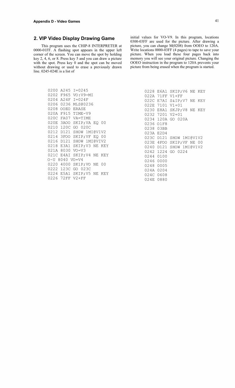
Appendix D - Video Games
2. VIP Video Display Drawing GameThis program uses the CHIP-8 INTERPRETER at
0000-01FF. A flashing spot appears in the upper leftcorner of the screen. You can move the spot by holdingkey 2, 4, 6, or 8. Press key 5 and you can draw a picturewith the spot. Press key 0 and the spot can be movedwithout drawing or used to erase a previously drawnline. 0245-024E is a list of
41
initial values for VO-V9. In this program, locations0300-03FF are used for the picture. After drawing apicture, you can change M(0208) from OOEO to 120A.Write locations 0000-03FF (4 pages) to tape to save yourpicture. When you load these four pages back intomemory you will see your original picture. Changing theOOEO instruction in the program to 120A prevents yourpicture from being erased when the program is started.
0200 A245 I=02450202 F965 VO:V9=MI0204 A24F I=024F0206 0236 MLS@02360208 OOEO ERASE020A F915 TIME-V9020C FA07 VA=TIME020E 3AOO SKIP;VA EQ 000210 120C GO 020C0212 D121 SHOW 1MI@V1V20214 3FOO SKIP;VF EQ 000216 D121 SHOW 1MI@VIV20218 E3A1 SKIP;V3 NE KEY021A 8030 VO=V3021C E4AI SKIP;V4 NE KEYO~U 8040 VO=V40220 4000 SK1P;VO NE 000222 123C GO 023C0224 E5A1 SKIP;V5 NE KEY0226 72FF V2+FF
0228 E6A1 SKIP;V6 NE KEY022A 71FF V1+FF022C E7AI S&IP;V7 NE KEY022E 7101 V1+010230 E8A1 SKJP;V8 NE KEY0232 7201 V2+010234 120A GO 020A0236 OlF80238 03BB023A E2D4023C D121 SHOW 1MI@V1V2023E 4FOO SKIP;VF NE 000240 D121 SHOW 1MI@V1V20242 1224 GO 02240244 01000246 00000248 0005024A 0204024C 0608024E 0880

67
Appendix E - Logic Diagrams
Fig. E-1 Microprocessor and Display InterfaceCircuits
Fig. E-2 ROM Circuits and Expansion Interface
Fig. E-3 Keyboard, Decoding, Audio Oscillator,and Cassette Interface Circuits
Fig. E-4 RAM Circuits
Fig. E-5 Power Supply Circuit and ByteInput/Output Interface

68 RCA COSMAC VIP Instruction Manual
Fig. E-1 - Microprocessor and Display Interface Circuits

Fig. E-2 - ROM Circuits and Expansion Interface
Appendix E - Logic Diagrams 69

70 RCA COSMAC VIP Instruction Manual
Fig. E-3 - Keyboard, Decoding, Audio Oscillator,and Cassette Interface Circuits

Appendix E - Logic Diagram's 71
Fig. E-4 - RAM Circuits

Fig. E-5 - Power Supply Circuit and Byte Input/Output Interface
72 RCA COSMAC VIP Instruction Manuel

Fig. E-5 - Power Supply Circult and Byte Input/Output Interface
72 RCA COSMAC VIP Instruction Manual

73
Appendix F -Board Layout, Parts List, and Expansion Notes
1. Printed Circuit Board Layout
2. Parts List for RCA COSMAC VIP CDP18S711

74 , RCA COSMAC VIP Instruction Manual


Appendix F - Board Layout, Parts List, and Assembly Instructions -76
2. Parts List for RCA COSMAC VIP CDP18S711
Type Number Qty. DescriptionIntegrated Circuits - SuppliedCDP1802 Ul 1 COSMAC MicroprocessorCDPI 861 U2 1 Video InterfaceSN74L00N U3 1 Quad NAND Low PowerSN7474N U4 1 Dual D-Type Flip-FlopCD4049 U5 1 Hex Inverting BufferCD4013 U6 1 Dual D-Type Flip-FlopCD4011 U7 1 Quad 2-Input NAND GateCD4042 U8 1 Quad Clocked "D" LatchCD4556 U9 1 Dual Binary 1 of 4 DecoderCDPR566 U10 1 512 x 8-Bit Static ROM (Programmed CDP1832)CD4051 Ull 1 Binary 1 of 8 DecoderCD4028 U12 1 BCD-to-Decimal DecoderCD4515 U13 1 4-Bit Latch/] of 16 DecoderCA3401 U14 1 Quad Single-Supply Op-AmpCA555CE U15 1 Timer2114 or TMS4045 U16-U19 4 1 K x 4-Bit Static RAMCD4508 U24,U25 2 Dual 4-Bit LatchCD4050 U26,U27 2 Hex BufferIntegrated Circuits - Optional2114 or TMS4045 U20-U23 4 1 K x 4-Bit Static RAM
Capacitors - SuppliedCl,Cl0 2 4.7 uF 35 V ElectrolyticC2 1 100 uF 16 V ElectrolyticC3 1 0.0047 uF 50 V Poly Film (472)C4,C5 2 0.47 uF 50 VC6,C7,C13 3 0.0 1 uF 50 V Poly Film (103)C8,C12 2 1 uF 50 V ElectrolyticC9 1 22 uF 16 V ElectrolyticC11 1 470 pF 500 V DiscC14 1 33 pF ± 10% 1 kV
(Continued on next page)


76 RCA COSMAC VIP Instruction Manual
2. Parts List for RCA COSMAC VIP CDP18S711 (Continued)
Type Number Qty. DescriptionResistors - Supplied (1 /4 W except as noted)
RI 1 3.3 K ohmR3 R5 RISRl6, R33 7 10 K ohmR39, R40R2, R17 2 1 K ohmR6-RI4R19, R20R22-R30, R36 28 22 K ohmR41-R47R18, R21 2 100 ohmR31, R32R37, R38 470 ohmR50R34 1 100 K ohmR35, R49 3 1 megohmR52R48 1 10 ohm 1/2 WR51 1 4.7 K ohmR4 1 200 ohm
Miscellaneous - SuppliedI N914 CR1 through 5 Diode
CR5HP5082-4494 3 Red LED
1 3.521280 MHz Crystal7 101 -S-D-V30-B Sl 1 SPDT Toggle Switch; C&KE7807 1 Panel Dress Nut for Switch; C&K18SO22 1 Printed Circuit BoardM-1651.0 1 Keyboard, Centralab
1 Cover, Thermoplastic7 Rubber Feet
C931802 4 18-Pin IC SocketC932402 1 24-Pin IC SocketC934002 1 40-Pin IC SocketCDP18S023 1 Power Supply, Regulated; 5 V dc, 600 mA; 110 V 50/60 Hz
6 Cable Straps1 Speaker
JI,J2 2 44-Pin ConnectorMPM-201 1 User Manual for the CDP1802 COSMAC MicroprocessorMPM-920 1 Instruction Summary for the CDP 1802 COSMAC MicroprocessorVIP-311 1 RCA COSMAC VIP Instruction Manual
Connectors, cables, hardwareMiscellaneous - OptionalLAD66A2CD 1 Heat Sink; IERC
2 4-40 1/4" Binder Hd. Machine Screws and Nuts7805 U28 1 Voltage Regulator


regulator IC) to the card together with an appropriateheat sink. Make sure the U28 lead pads on the PC DCcard don't touch the heat sink. Disconnect the +5 V supply at the + V DC and GND pads and connect yourunregulated 8-10 V DC power supply to these pads.This on-card regulator will handle up to I ampere ofcurrent and is useful for system expansion. Do not use aplastic cover for your PC card when this on-cardregulator option is used. Air How is needed to permitthe regulator to operate properly.
Appendix F - Board Layout, Parts List, and Assembly Instructions 77
3. COSMAC VIP Expansion Notes
a. Soldering the PC Board
b. Voltage Regulator Option
An unregulated 8-10 volt DC power supply canbe used with the COSMAC VIP card if desired. Cut
LK1 on the PC card. Add U28 (a 7805, 5-volt
c. Additional 2048-Byte RAM Option
To increase your COSMAC VIP RAM to a total of4096 bytes, add U20-U23 to the PC card by pluggingunits into the four sockets provided. Measure the powersupply current to be sure it does not exceed the capacityof the +5 V DC power pack supplied with the VIP (600mA). If you require additional power supply current usea regulated +5 V DC supply capable of supplying Iampere or use an unregulated 8-10 V DC supply withthe voltage regulator option on the cards.
In the event you wish to make some changes oradd components requiring soldering, you should havesome experience building electronic kits. The PCboard pads are small and close together requiringextra caution when soldering to avoid shorts or solderbridges. Use a low-heat, small-tipped, groundedsoldering iron. Keep it clean. Use small gauge, rosincore 60/40 solder. Preheat the connection and applyjust enough solder to "wet" the connection. Avoidusing excessive amounts of solder because it will flowthrough the plated-through holes and form "blobs"on the top of the card. Excessive or protracted heatfrom the soldering iron can damage some of thecomponents.