cortex m3 programming - ryerson university m3 programming ee8205: embedded computer systems...
TRANSCRIPT
© G.N. Khan Cortex-M3 CPU Programming – EE8205: Embedded Computer Systems Page: 1
Cortex M3 Programming
EE8205: Embedded Computer Systems http://www.ee.ryerson.ca/~courses/EE8205/
Dr. Gul N. Khan http://www.ee.ryerson.ca/~gnkhan
Electrical and Computer Engineering
Ryerson University
Overview • ARM Cortex-M* Programming • Data Processing & Load/Store Instructions • Control Instruction and Conditional Execution - IT Instructions • Functional Call and Return • Temporary Variables
Text by Lewis: Chapter 6 and 7- part of Chapter 6, 7 and M3 Data Sheets Text by M. Wolf: part of Chapters/Sections 2.1, 2.2 and 2.3
© G.N. Khan Cortex-M3 CPU Programming – EE8205: Embedded Computer Systems Page: 2
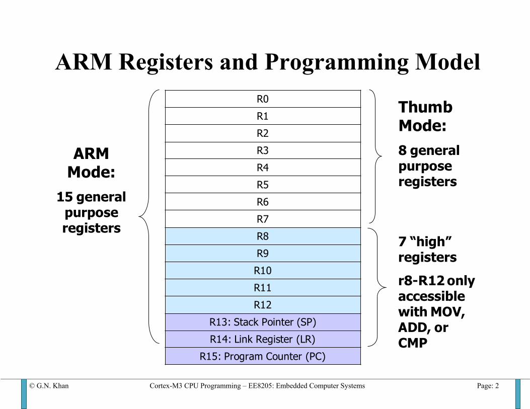
ARM Registers and Programming Model
R0
R1
R2
R3
R4
R5
R6
R7
R8
R9
R10
R11
R12
R13: Stack Pointer (SP)
R14: Link Register (LR)
R15: Program Counter (PC)
Thumb Mode:8 general purpose registers
7 “high” registers
r8-R12 only accessible with MOV, ADD, or CMP
ARM Mode:
15 general purpose registers

© G.N. Khan Cortex-M3 CPU Programming – EE8205: Embedded Computer Systems Page: 3
ARM Data Processing Instructions
Opcode [24:21]
Mnemonic Meaning Effect
0000 AND Logical bit-wise AND Rd := Rn AND Op2 0001 EOR Logical bit-wise exclusive OR Rd := Rn EOR Op2 0010 SUB Subtract Rd := Rn - Op2 0011 RSB Reverse subtract Rd := Op2 - Rn 0100 ADD Add Rd := Rn + Op2 0101 ADC Add with carry Rd := Rn + Op2 + C 0110 SBC Subtract with carry Rd := Rn - Op2 + C - 1 0111 RSC Reverse subtract with carry Rd := Op2 - Rn + C - 1 1000 TST Test Scc on Rn AND Op2 1001 TEQ Test equivalence Scc on Rn EOR Op2 1010 CMP Compare Scc on Rn - Op2 1011 CMN Compare negated Scc on Rn + Op2 1100 ORR Logical bit-wise OR Rd := Rn OR Op2 1101 MOV Move Rd := Op2 1110 BIC Bit clear Rd := Rn AND NOT Op2 1111 MVN Move negated Rd := NOT Op2
© G.N. Khan Cortex-M3 CPU Programming – EE8205: Embedded Computer Systems Page: 4
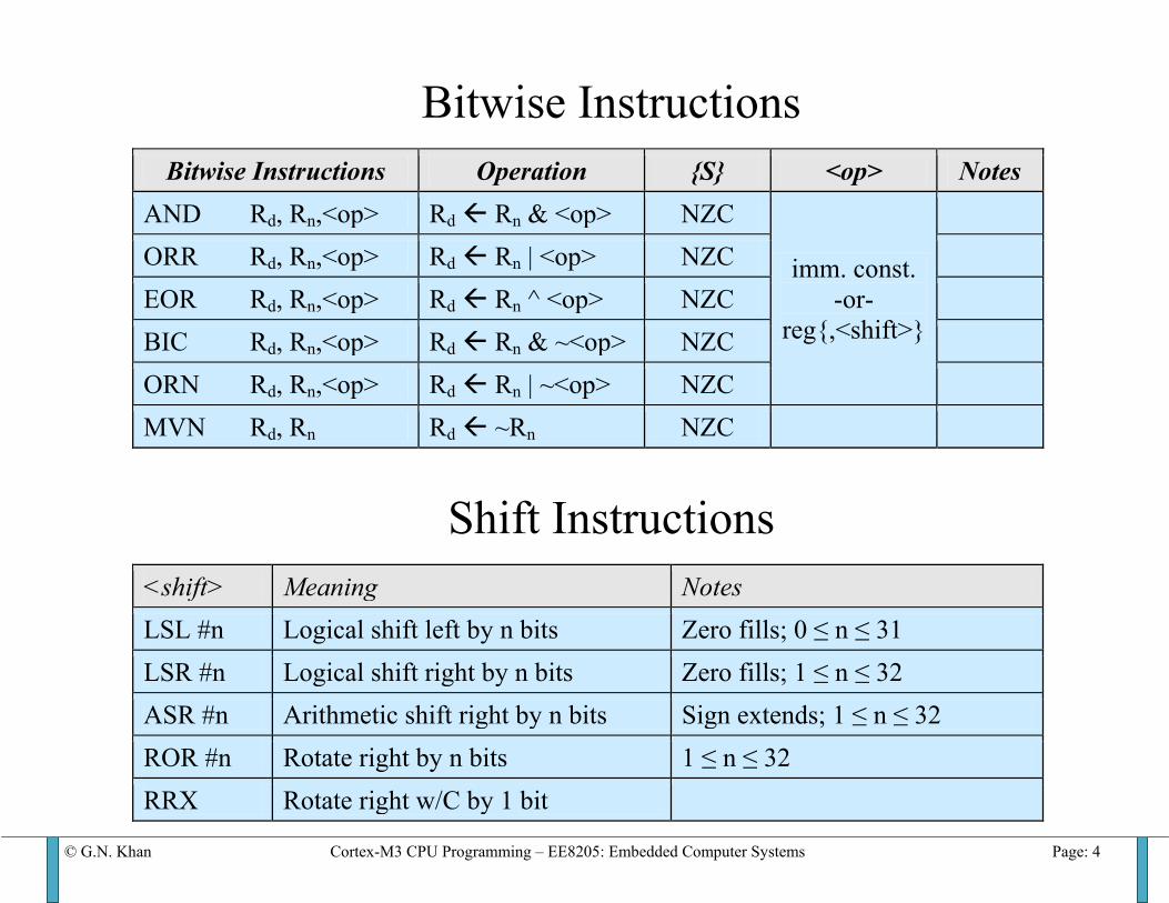
Bitwise Instructions
Bitwise Instructions Operation {S} <op> Notes AND Rd, Rn,<op> Rd Rn & <op> NZC
imm. const. -or-
reg{,<shift>}
ORR Rd, Rn,<op> Rd Rn | <op> NZC EOR Rd, Rn,<op> Rd Rn ^ <op> NZC BIC Rd, Rn,<op> Rd Rn & ~<op> NZC ORN Rd, Rn,<op> Rd Rn | ~<op> NZC MVN Rd, Rn Rd ~Rn NZC
Shift Instructions
<shift> Meaning Notes LSL #n Logical shift left by n bits Zero fills; 0 ≤ n ≤ 31 LSR #n Logical shift right by n bits Zero fills; 1 ≤ n ≤ 32 ASR #n Arithmetic shift right by n bits Sign extends; 1 ≤ n ≤ 32 ROR #n Rotate right by n bits 1 ≤ n ≤ 32 RRX Rotate right w/C by 1 bit
© G.N. Khan Cortex-M3 CPU Programming – EE8205: Embedded Computer Systems Page: 5
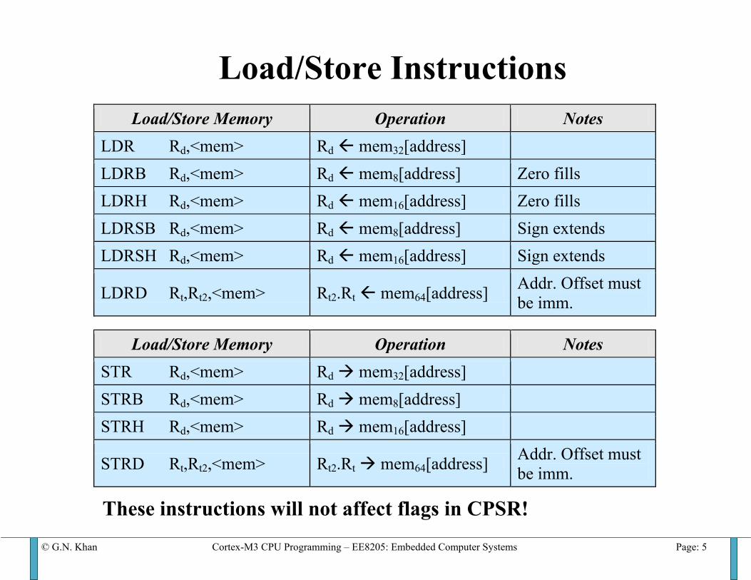
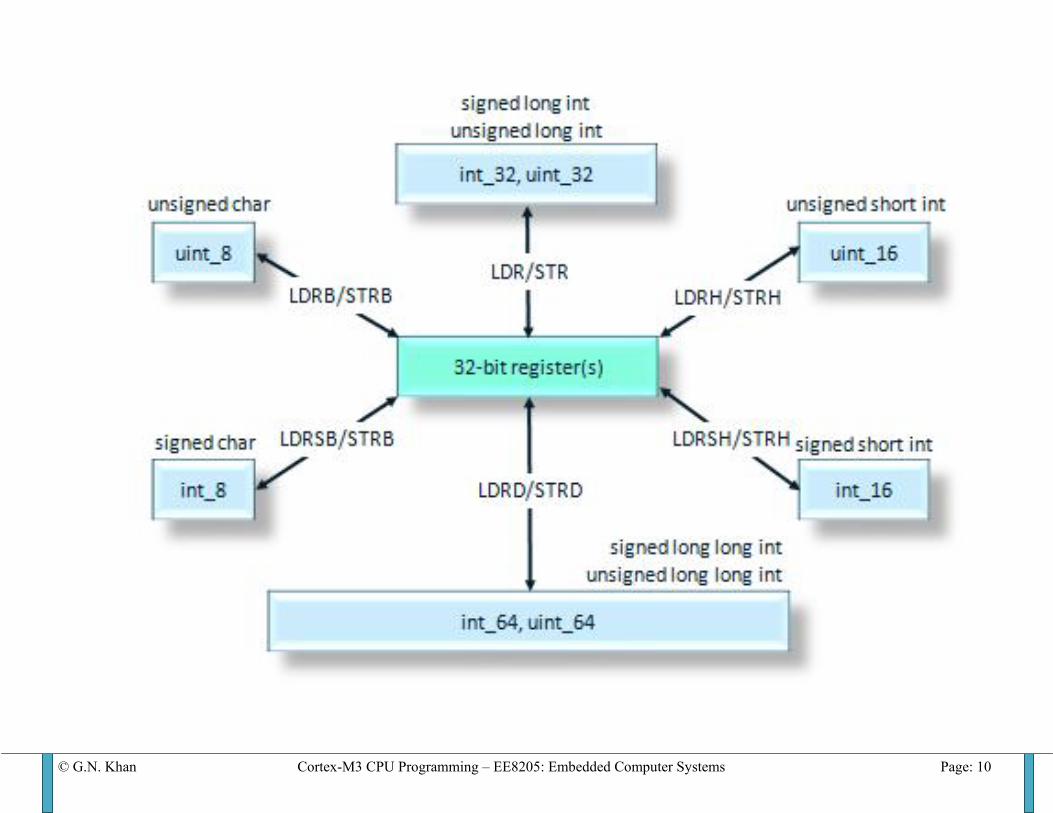
Load/Store Instructions
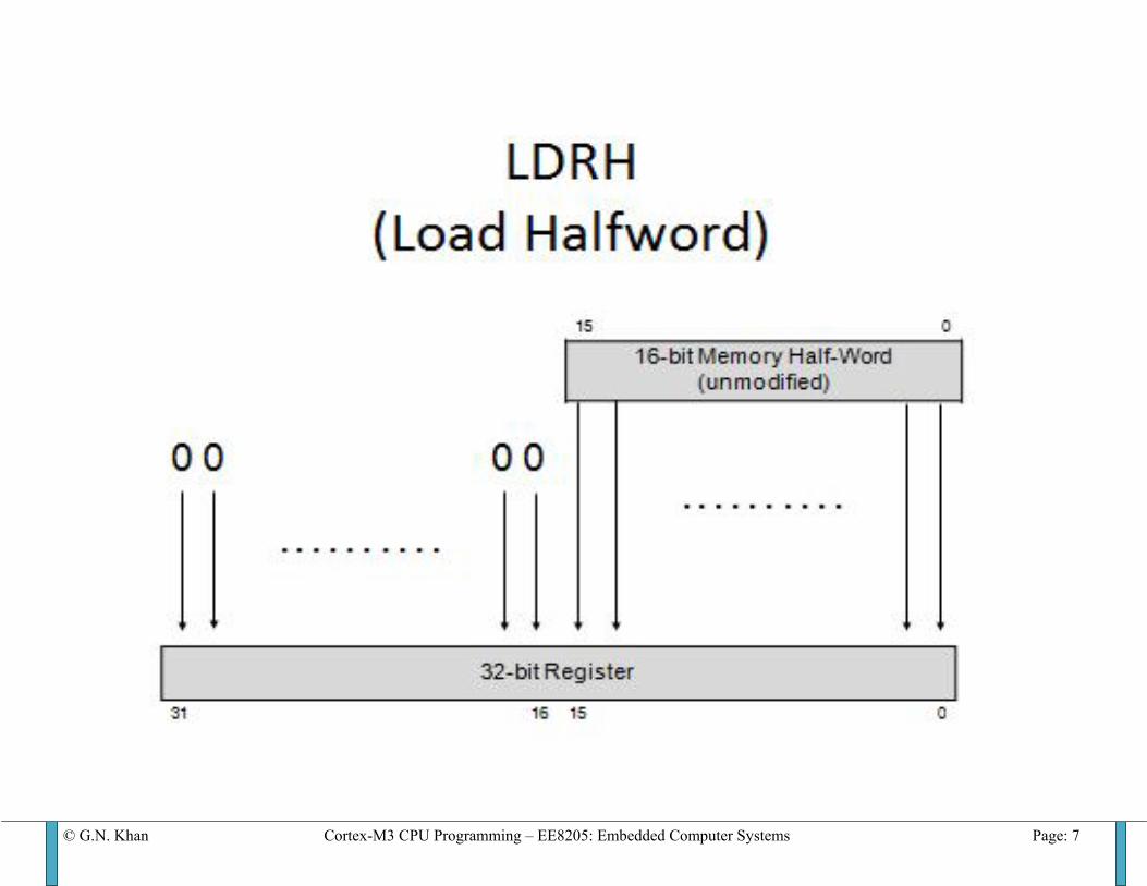
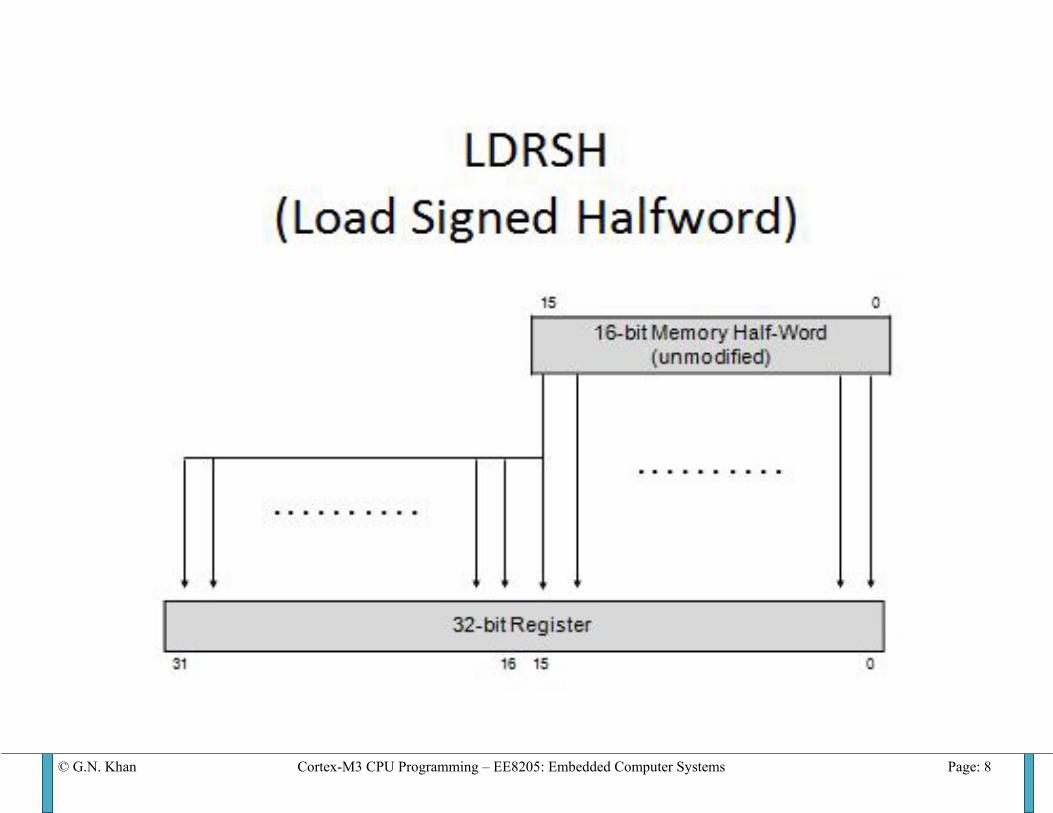
Load/Store Memory Operation Notes LDR Rd,<mem> Rd mem32[address] LDRB Rd,<mem> Rd mem8[address] Zero fills LDRH Rd,<mem> Rd mem16[address] Zero fills LDRSB Rd,<mem> Rd mem8[address] Sign extends LDRSH Rd,<mem> Rd mem16[address] Sign extends
LDRD Rt,Rt2,<mem> Rt2.Rt mem64[address] Addr. Offset must be imm.
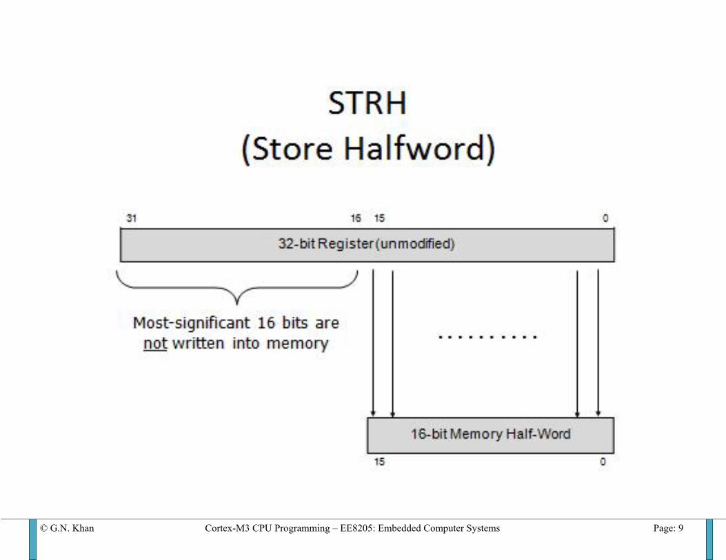
Load/Store Memory Operation Notes STR Rd,<mem> Rd mem32[address] STRB Rd,<mem> Rd mem8[address] STRH Rd,<mem> Rd mem16[address] STRD Rt,Rt2,<mem> Rt2.Rt mem64[address] Addr. Offset must
be imm.
These instructions will not affect flags in CPSR!
© G.N. Khan Cortex-M3 CPU Programming – EE8205: Embedded Computer Systems Page: 6
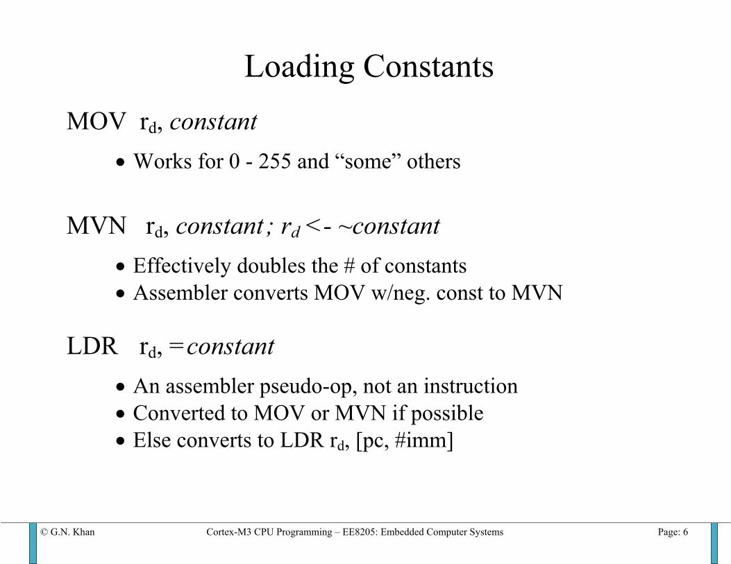
Loading Constants MOV rd, constant
• Works for 0 - 255 and “some” others
MVN rd, constant ; rd <- ~constant
• Effectively doubles the # of constants • Assembler converts MOV w/neg. const to MVN
LDR rd, =constant
• An assembler pseudo-op, not an instruction • Converted to MOV or MVN if possible • Else converts to LDR rd, [pc, #imm]
© G.N. Khan Cortex-M3 CPU Programming – EE8205: Embedded Computer Systems Page: 7
© G.N. Khan Cortex-M3 CPU Programming – EE8205: Embedded Computer Systems Page: 8
© G.N. Khan Cortex-M3 CPU Programming – EE8205: Embedded Computer Systems Page: 9
© G.N. Khan Cortex-M3 CPU Programming – EE8205: Embedded Computer Systems Page: 10
© G.N. Khan Cortex-M3 CPU Programming – EE8205: Embedded Computer Systems Page: 11
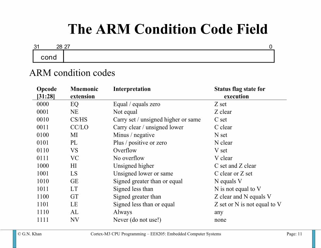
The ARM Condition Code Field
ARM condition codes
cond31 28 27 0
Opcode [31:28]
Mnemonic extension
Interpretation Status flag state for execution
0000 EQ Equal / equals zero Z set 0001 NE Not equal Z clear 0010 CS/HS Carry set / unsigned higher or same C set 0011 CC/LO Carry clear / unsigned lower C clear 0100 MI Minus / negative N set 0101 PL Plus / positive or zero N clear 0110 VS Overflow V set 0111 VC No overflow V clear 1000 HI Unsigned higher C set and Z clear 1001 LS Unsigned lower or same C clear or Z set 1010 GE Signed greater than or equal N equals V 1011 LT Signed less than N is not equal to V 1100 GT Signed greater than Z clear and N equals V 1101 LE Signed less than or equal Z set or N is not equal to V 1110 AL Always any 1111 NV Never (do not use!) none
© G.N. Khan Cortex-M3 CPU Programming – EE8205: Embedded Computer Systems Page: 12
© G.N. Khan Cortex-M3 CPU Programming – EE8205: Embedded Computer Systems Page: 13
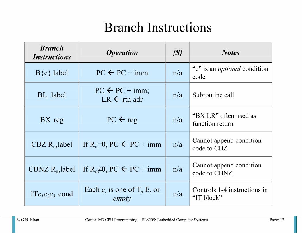
Branch Instructions
Branch Instructions Operation {S} Notes
B{c} label PC PC + imm n/a “c” is an optional condition code
BL label PC PC + imm; LR rtn adr n/a Subroutine call
BX reg PC reg n/a “BX LR” often used as function return
CBZ Rn,label If Rn=0, PC PC + imm n/a Cannot append condition code to CBZ
CBNZ Rn,label If Rn≠0, PC PC + imm n/a Cannot append condition code to CBNZ
ITc1c2c3 cond Each ci is one of T, E, or empty n/a Controls 1-4 instructions in
“IT block”
© G.N. Khan Cortex-M3 CPU Programming – EE8205: Embedded Computer Systems Page: 14
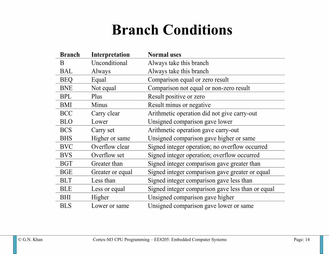
Branch Conditions
Branch Interpretation Normal uses B BAL
Unconditional Always
Always take this branch Always take this branch
BEQ Equal Comparison equal or zero result BNE Not equal Comparison not equal or non-zero result BPL Plus Result positive or zero BMI Minus Result minus or negative BCC BLO
Carry clear Lower
Arithmetic operation did not give carry-out Unsigned comparison gave lower
BCS BHS
Carry set Higher or same
Arithmetic operation gave carry-out Unsigned comparison gave higher or same
BVC Overflow clear Signed integer operation; no overflow occurred BVS Overflow set Signed integer operation; overflow occurred BGT Greater than Signed integer comparison gave greater than BGE Greater or equal Signed integer comparison gave greater or equal BLT Less than Signed integer comparison gave less than BLE Less or equal Signed integer comparison gave less than or equal BHI Higher Unsigned comparison gave higher BLS Lower or same Unsigned comparison gave lower or same
© G.N. Khan Cortex-M3 CPU Programming – EE8205: Embedded Computer Systems Page: 15
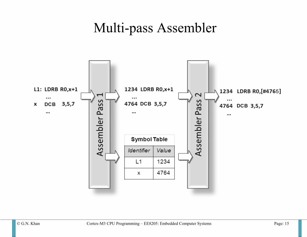
Multi-pass Assembler
© G.N. Khan Cortex-M3 CPU Programming – EE8205: Embedded Computer Systems Page: 16
Status Registers (xPSR)
31
30
29
28
27
26
25
24
23
16
15
10 9 8 0
N C Z V Q
0 or exception #
ICI/IT T ICI/IT
Bits Name Description
31 N Negative (bit 31 of result is 1)30 C Unsigned Carry29 Z Zero or Equal28 V Signed Overflow
Most important for application programming
APSR
IPSR
EPSR
© G.N. Khan Cortex-M3 CPU Programming – EE8205: Embedded Computer Systems Page: 17
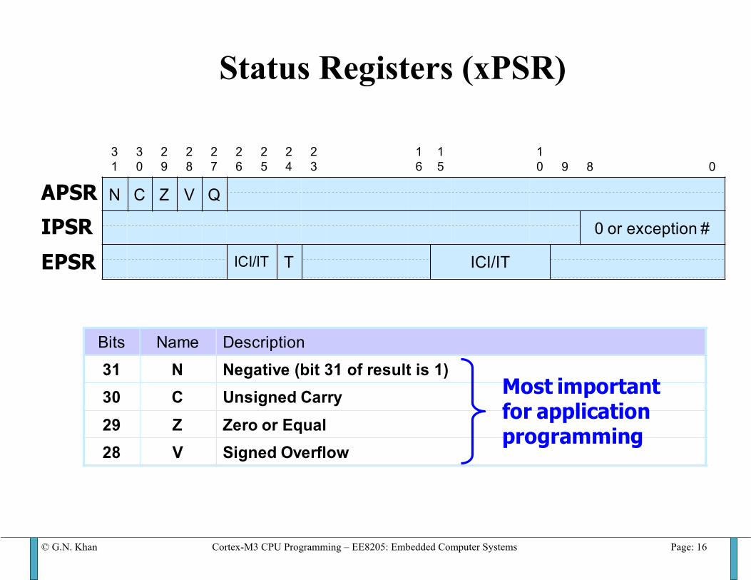
PSR: Program Status Register Divided into three bit fields • Application Program Status Register (APSR) • Interrupt Program Status Register (IPSR) • Execution Program Status Register (EPSR)
Q-bit is the sticky saturation bit and supports two rarely used instructions (SSAT and USAT) SSAT{cond} Rd, #sat, Rm{, shift} • EPSR holds the exception number is exception processing. • ICI/IT bits hold the state information for IT block instructions or
instructions that are suspended during interrupt processing. • T bit is always 1 to indicate Thumb instructions.
© G.N. Khan Cortex-M3 CPU Programming – EE8205: Embedded Computer Systems Page: 18
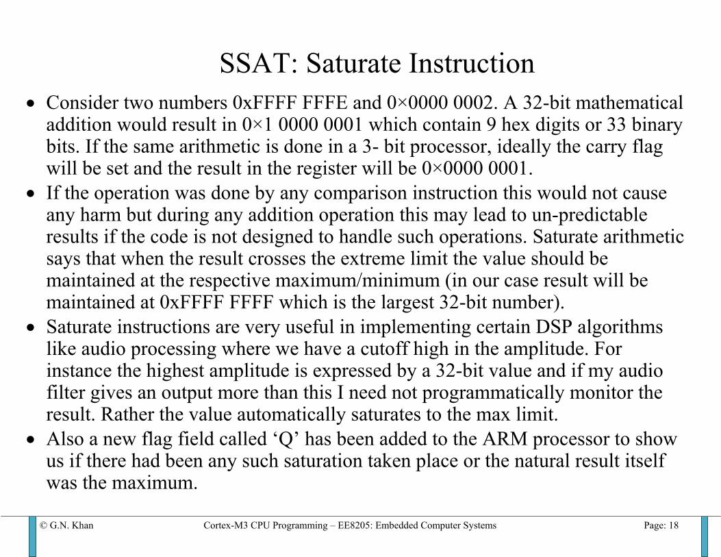
SSAT: Saturate Instruction
• Consider two numbers 0xFFFF FFFE and 0×0000 0002. A 32-bit mathematical addition would result in 0×1 0000 0001 which contain 9 hex digits or 33 binary bits. If the same arithmetic is done in a 3- bit processor, ideally the carry flag will be set and the result in the register will be 0×0000 0001.
• If the operation was done by any comparison instruction this would not cause any harm but during any addition operation this may lead to un-predictable results if the code is not designed to handle such operations. Saturate arithmetic says that when the result crosses the extreme limit the value should be maintained at the respective maximum/minimum (in our case result will be maintained at 0xFFFF FFFF which is the largest 32-bit number).
• Saturate instructions are very useful in implementing certain DSP algorithms like audio processing where we have a cutoff high in the amplitude. For instance the highest amplitude is expressed by a 32-bit value and if my audio filter gives an output more than this I need not programmatically monitor the result. Rather the value automatically saturates to the max limit.
• Also a new flag field called ‘Q’ has been added to the ARM processor to show us if there had been any such saturation taken place or the natural result itself was the maximum.

© G.N. Khan Cortex-M3 CPU Programming – EE8205: Embedded Computer Systems Page: 19
SSAT or USAT Instructions op{cond} Rd, #n, Rm {, shift #s} op = SSAT Saturates a signed value to a signed range. USAT Saturates a signed value to an unsigned range. Cond condition code Rd Specifies the destination register. n Specifies the bit position to saturate to:
n ranges from 1 to 32 for SSAT n ranges from 0 to 31 for USAT.
Rm Register containing the value to saturate. shift #s optional shift applied to Rm before saturating. These instructions saturate to a signed or unsigned n-bit value. SSAT instruction applies the specified shift, then saturates to the signed
range −2n-1 ≤ x ≤ 2n-1−1. The USAT instruction applies the specified shift, then saturates to the unsigned
range 0 ≤ x ≤ 2n−1.
© G.N. Khan Cortex-M3 CPU Programming – EE8205: Embedded Computer Systems Page: 20
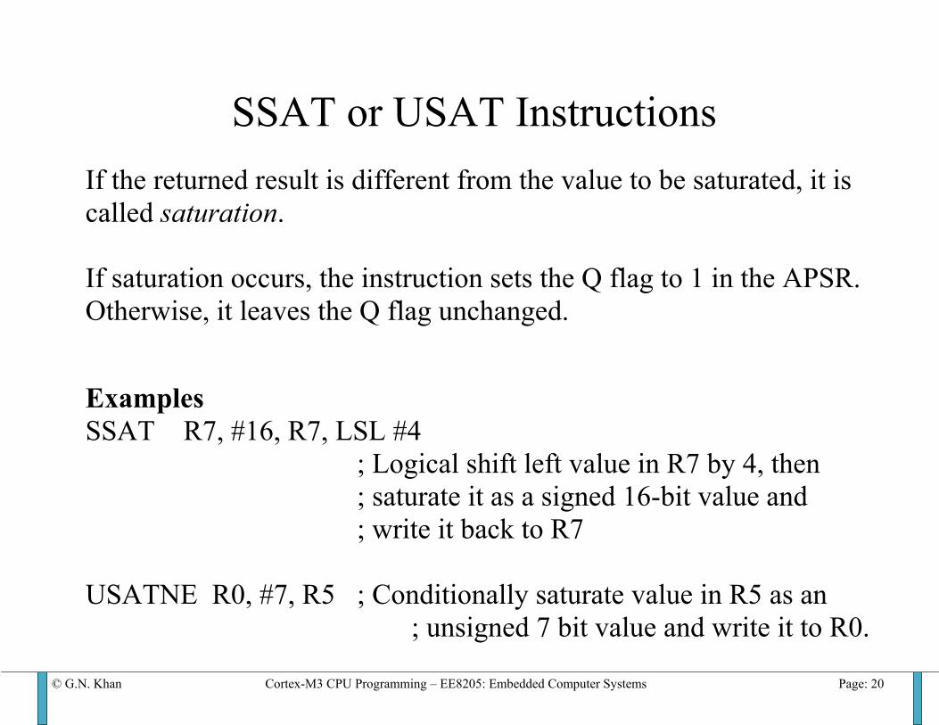
SSAT or USAT Instructions If the returned result is different from the value to be saturated, it is called saturation. If saturation occurs, the instruction sets the Q flag to 1 in the APSR. Otherwise, it leaves the Q flag unchanged. Examples SSAT R7, #16, R7, LSL #4 ; Logical shift left value in R7 by 4, then ; saturate it as a signed 16-bit value and ; write it back to R7 USATNE R0, #7, R5 ; Conditionally saturate value in R5 as an ; unsigned 7 bit value and write it to R0.
© G.N. Khan Cortex-M3 CPU Programming – EE8205: Embedded Computer Systems Page: 21
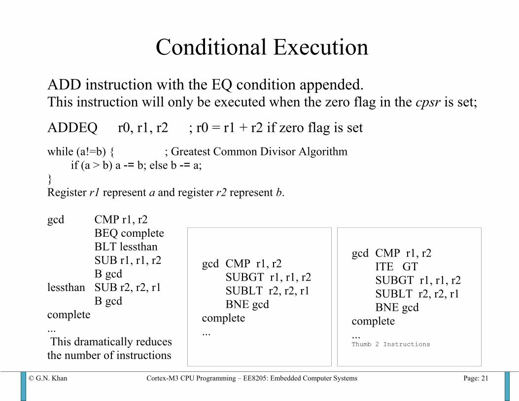
Conditional Execution ADD instruction with the EQ condition appended. This instruction will only be executed when the zero flag in the cpsr is set;
ADDEQ r0, r1, r2 ; r0 = r1 + r2 if zero flag is set while (a!=b) { ; Greatest Common Divisor Algorithm
if (a > b) a -= b; else b -= a; } Register r1 represent a and register r2 represent b. gcd CMP r1, r2
BEQ complete BLT lessthan SUB r1, r1, r2 B gcd
lessthan SUB r2, r2, r1 B gcd
complete ... This dramatically reduces the number of instructions
gcd CMP r1, r2 SUBGT r1, r1, r2 SUBLT r2, r2, r1 BNE gcd
complete ...
gcd CMP r1, r2 ITE GT SUBGT r1, r1, r2 SUBLT r2, r2, r1 BNE gcd
complete ... Thumb 2 Instructions
© G.N. Khan Cortex-M3 CPU Programming – EE8205: Embedded Computer Systems Page: 22
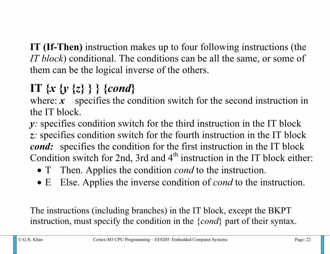
IT (If-Then) instruction makes up to four following instructions (the IT block) conditional. The conditions can be all the same, or some of them can be the logical inverse of the others.
IT {x {y {z} } } {cond} where: x specifies the condition switch for the second instruction in the IT block. y: specifies condition switch for the third instruction in the IT block z: specifies condition switch for the fourth instruction in the IT block cond: specifies the condition for the first instruction in the IT block Condition switch for 2nd, 3rd and 4th instruction in the IT block either: • T Then. Applies the condition cond to the instruction. • E Else. Applies the inverse condition of cond to the instruction.
The instructions (including branches) in the IT block, except the BKPT instruction, must specify the condition in the {cond} part of their syntax.
© G.N. Khan Cortex-M3 CPU Programming – EE8205: Embedded Computer Systems Page: 23
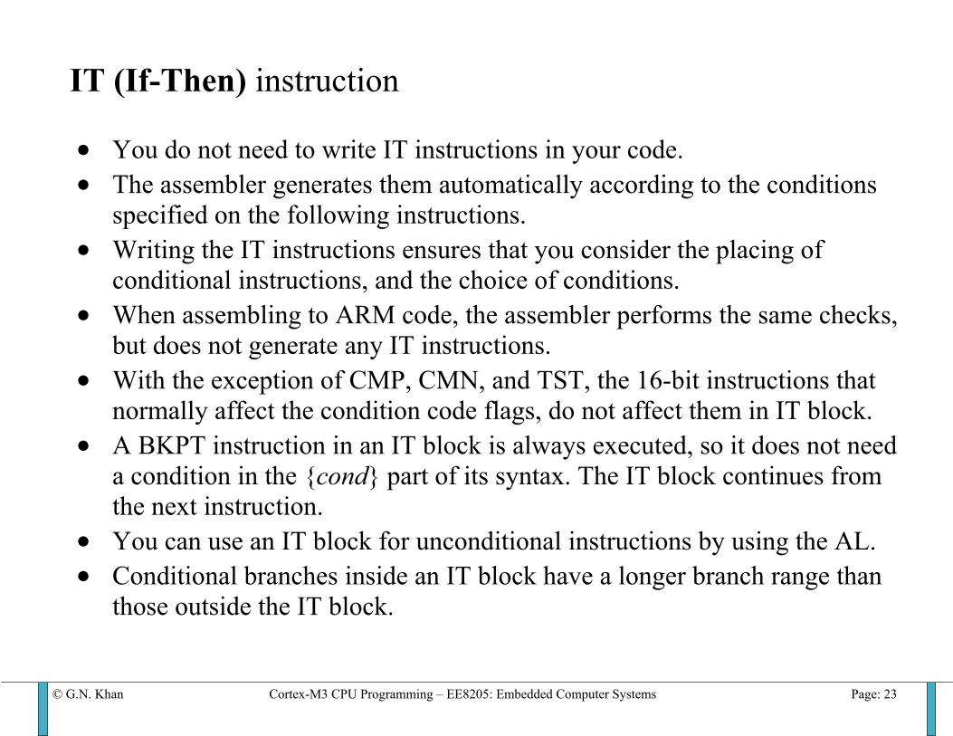
IT (If-Then) instruction • You do not need to write IT instructions in your code. • The assembler generates them automatically according to the conditions
specified on the following instructions. • Writing the IT instructions ensures that you consider the placing of
conditional instructions, and the choice of conditions. • When assembling to ARM code, the assembler performs the same checks,
but does not generate any IT instructions. • With the exception of CMP, CMN, and TST, the 16-bit instructions that
normally affect the condition code flags, do not affect them in IT block. • A BKPT instruction in an IT block is always executed, so it does not need
a condition in the {cond} part of its syntax. The IT block continues from the next instruction.
• You can use an IT block for unconditional instructions by using the AL. • Conditional branches inside an IT block have a longer branch range than
those outside the IT block.
© G.N. Khan Cortex-M3 CPU Programming – EE8205: Embedded Computer Systems Page: 24
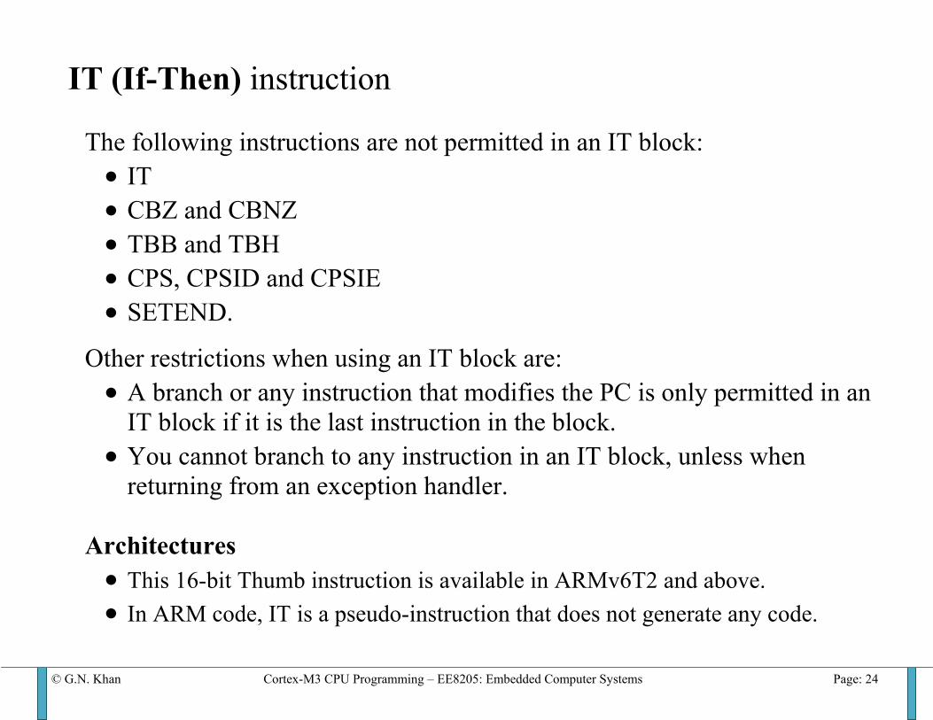
IT (If-Then) instruction The following instructions are not permitted in an IT block: • IT • CBZ and CBNZ • TBB and TBH • CPS, CPSID and CPSIE • SETEND.
Other restrictions when using an IT block are: • A branch or any instruction that modifies the PC is only permitted in an
IT block if it is the last instruction in the block. • You cannot branch to any instruction in an IT block, unless when
returning from an exception handler. Architectures • This 16-bit Thumb instruction is available in ARMv6T2 and above. • In ARM code, IT is a pseudo-instruction that does not generate any code.
© G.N. Khan Cortex-M3 CPU Programming – EE8205: Embedded Computer Systems Page: 25
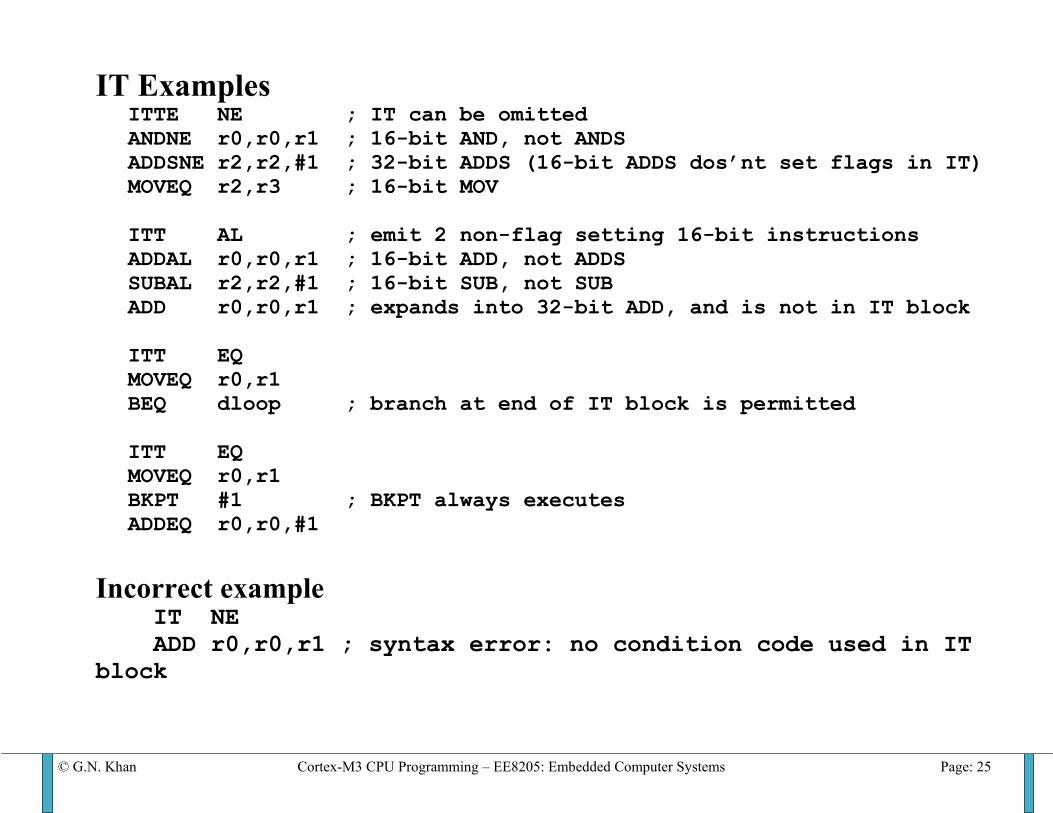
IT Examples ITTE NE ; IT can be omitted ANDNE r0,r0,r1 ; 16-bit AND, not ANDS ADDSNE r2,r2,#1 ; 32-bit ADDS (16-bit ADDS dos’nt set flags in IT) MOVEQ r2,r3 ; 16-bit MOV ITT AL ; emit 2 non-flag setting 16-bit instructions ADDAL r0,r0,r1 ; 16-bit ADD, not ADDS SUBAL r2,r2,#1 ; 16-bit SUB, not SUB ADD r0,r0,r1 ; expands into 32-bit ADD, and is not in IT block ITT EQ MOVEQ r0,r1 BEQ dloop ; branch at end of IT block is permitted ITT EQ MOVEQ r0,r1 BKPT #1 ; BKPT always executes ADDEQ r0,r0,#1
Incorrect example IT NE ADD r0,r0,r1 ; syntax error: no condition code used in IT block
© G.N. Khan Cortex-M3 CPU Programming – EE8205: Embedded Computer Systems Page: 26
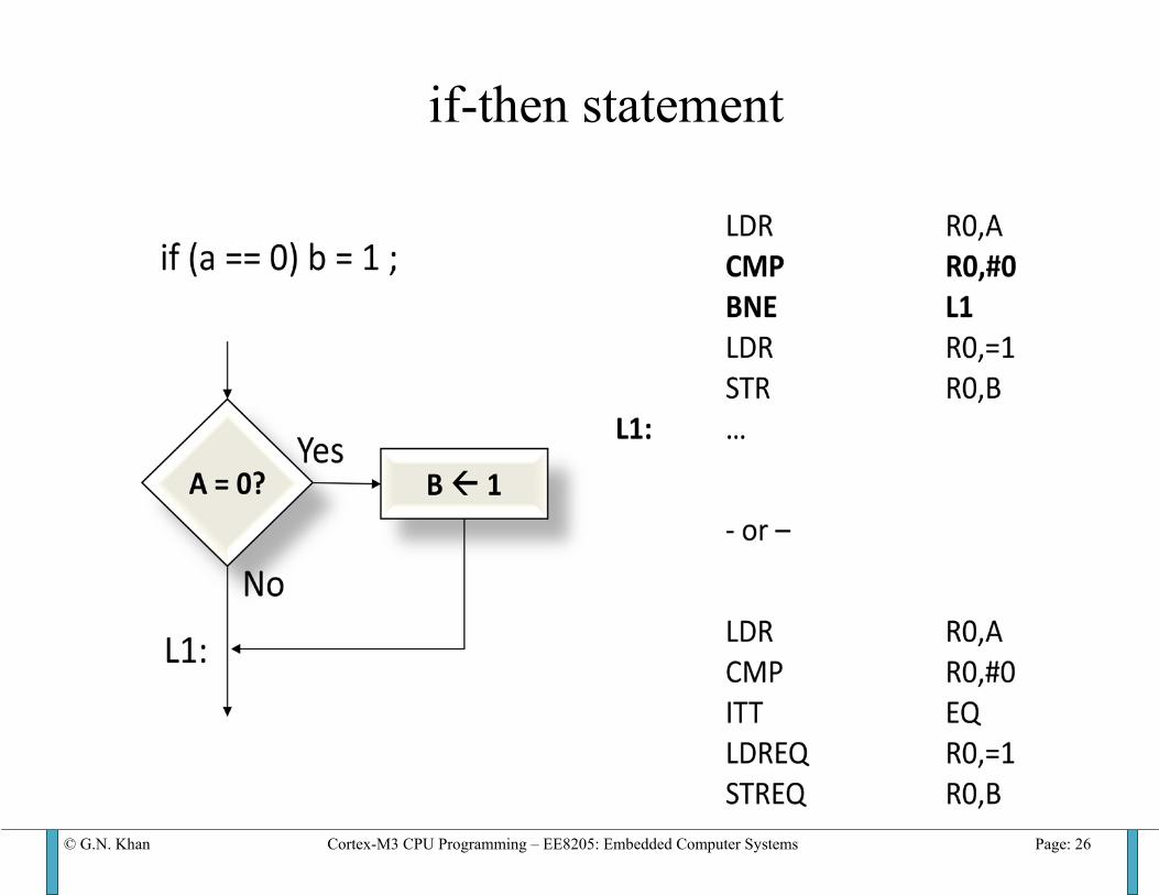
if-then statement
© G.N. Khan Cortex-M3 CPU Programming – EE8205: Embedded Computer Systems Page: 27
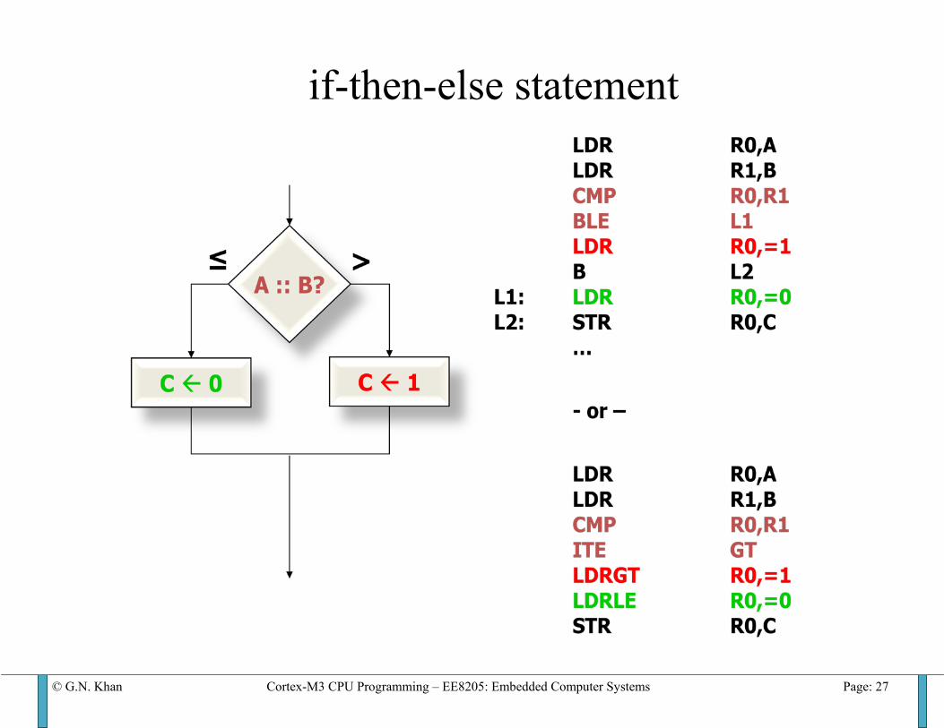
if-then-else statement
© G.N. Khan Cortex-M3 CPU Programming – EE8205: Embedded Computer Systems Page: 28
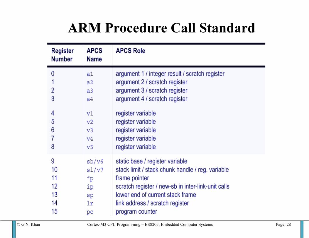
ARM Procedure Call Standard
© G.N. Khan Cortex-M3 CPU Programming – EE8205: Embedded Computer Systems Page: 29
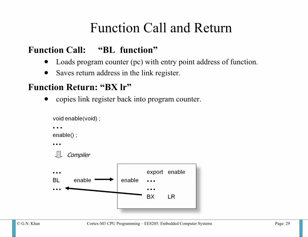
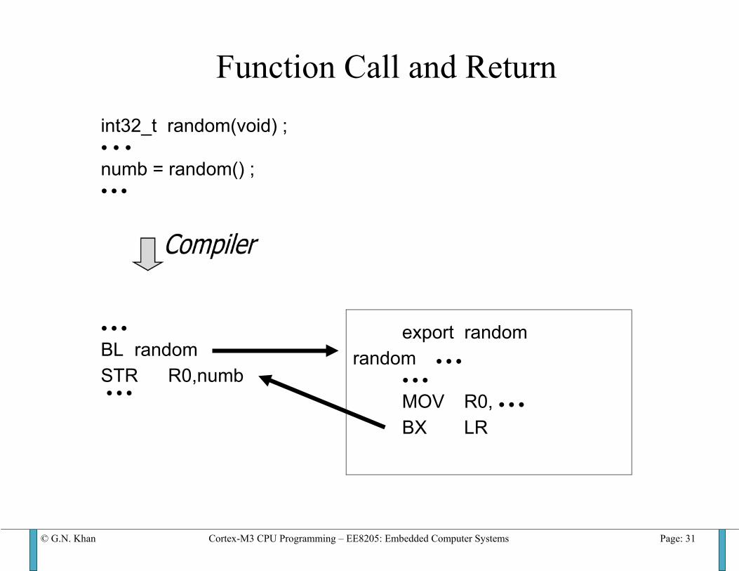
Function Call and Return Function Call: “BL function”
• Loads program counter (pc) with entry point address of function. • Saves return address in the link register.
Function Return: “BX lr” • copies link register back into program counter.
© G.N. Khan Cortex-M3 CPU Programming – EE8205: Embedded Computer Systems Page: 30
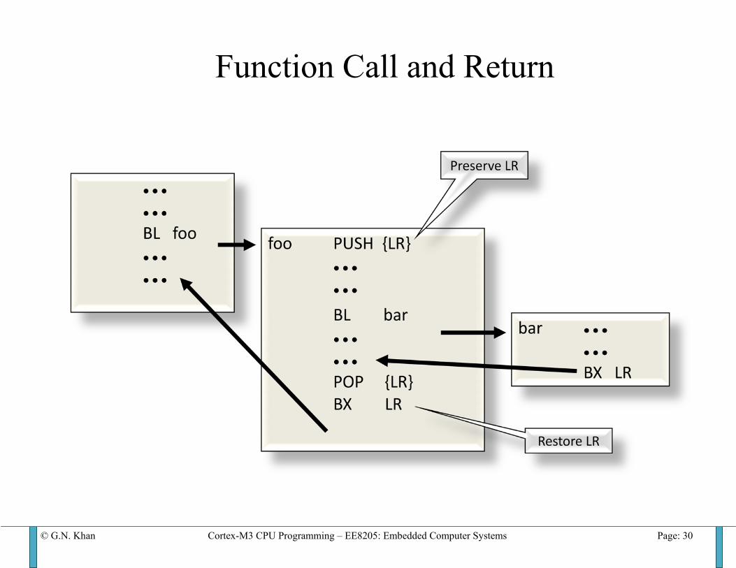
Function Call and Return
© G.N. Khan Cortex-M3 CPU Programming – EE8205: Embedded Computer Systems Page: 31
Function Call and Return int32_t random(void) ; ● ● ● numb = random() ; ● ● ●
● ● ● BL random STR R0,numb ● ● ●
export random random ● ● ● ● ● ● MOV R0, ● ● ● BX LR
© G.N. Khan Cortex-M3 CPU Programming – EE8205: Embedded Computer Systems Page: 32
Temporary Variables
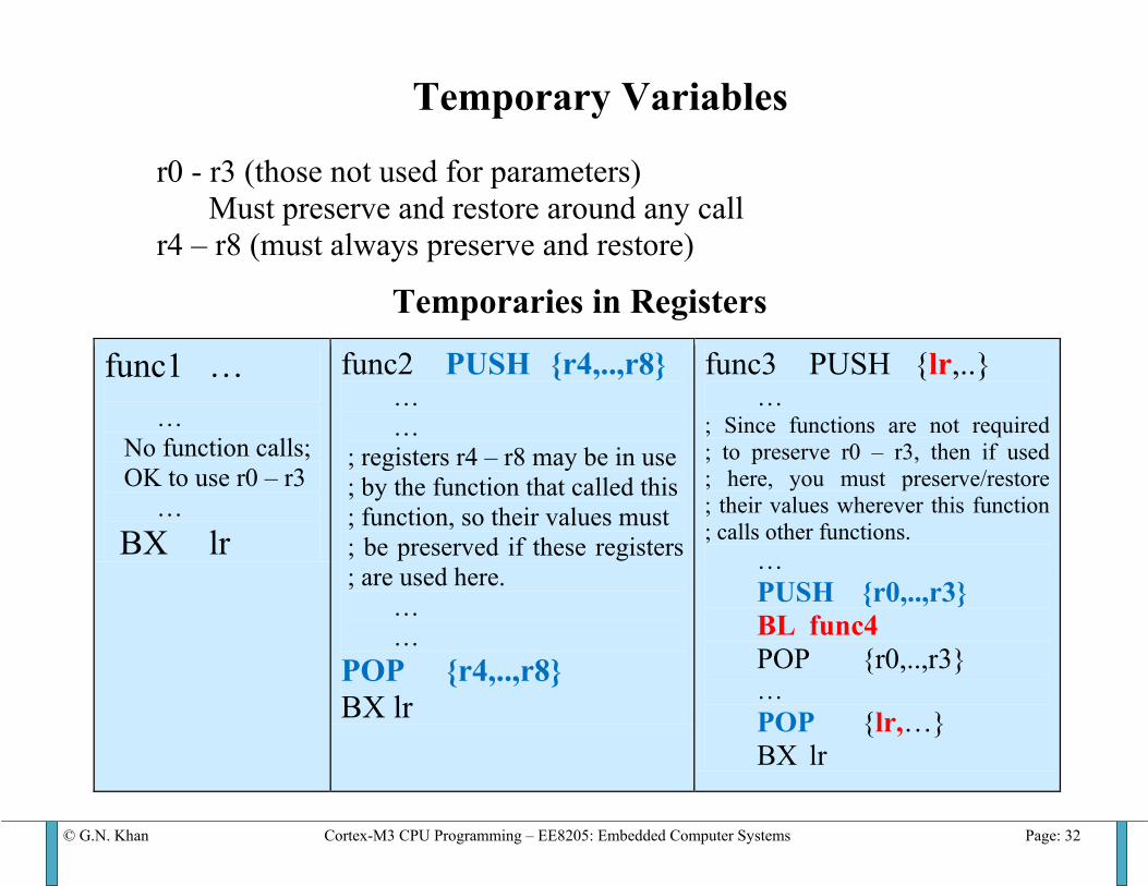
r0 - r3 (those not used for parameters) Must preserve and restore around any call
r4 – r8 (must always preserve and restore)
Temporaries in Registers
func1 … … No function calls; OK to use r0 – r3 … BX lr
func2 PUSH {r4,..,r8} … … ; registers r4 – r8 may be in use ; by the function that called this ; function, so their values must ; be preserved if these registers ; are used here. … … POP {r4,..,r8} BX lr
func3 PUSH {lr,..} … ; Since functions are not required ; to preserve r0 – r3, then if used ; here, you must preserve/restore ; their values wherever this function ; calls other functions. … PUSH {r0,..,r3} BL func4 POP {r0,..,r3} … POP {lr,…} BX lr
© G.N. Khan Cortex-M3 CPU Programming – EE8205: Embedded Computer Systems Page: 33
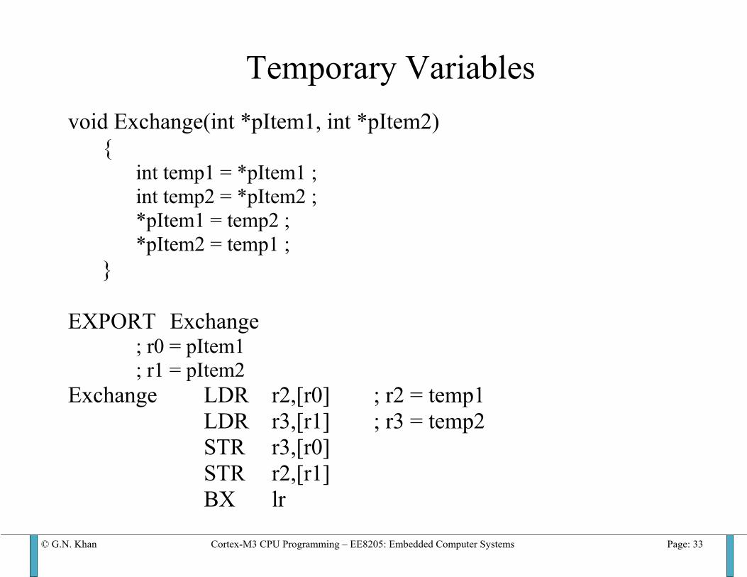
Temporary Variables void Exchange(int *pItem1, int *pItem2) { int temp1 = *pItem1 ; int temp2 = *pItem2 ; *pItem1 = temp2 ; *pItem2 = temp1 ; } EXPORT Exchange ; r0 = pItem1 ; r1 = pItem2 Exchange LDR r2,[r0] ; r2 = temp1 LDR r3,[r1] ; r3 = temp2 STR r3,[r0] STR r2,[r1] BX lr