corrosion resistant coating of metal bipolar plates for
TRANSCRIPT

1
Corrosion Resistant Coating of Metal Bipolar Plates for PEM Fuel Cells
Feb. 14, 2017
Conghua “CH” Wang
Workshop on Research and Development Needs for Bipolar Plates for PEM Fuel Cell Technologies
Southfield, MI

Demonstrated in PEM electrolyzer at Giner and Proton
Demonstrated in single cell test
Will be demonstrated in Auto FC stack with Ford
Demonstrated in single cell test
Demonstrated in Auto FC stack
with Ford
Metal Plate Technology Development at TreadStone
2006 2007 2008 2009 2010 2011 2012 2013 2014 2015 2016
2
Coating with precious metals Exceptional stability and electrical conductivity. Focus is on precious metal usage reduction and adhesion
of coating on substrate. Reduce the precious metal coating thickness. Reduce the surface coverage of precious metal
on metal substrate.
Coating without precious metals Low material cost. Final cost is dominated by the
coating processing cost. Challenges in long term durability, especially at high
potential transit conditions. Metal nitride is the most investigated coating.
The challenge is the stability of the coating at stack transient operation conditions.
Graphite coating is used in some systems. A thick coating is needed to meet the long term (>5,000 hrs) operation requirement. The fabrication cost of the thick coating is an issue.
Conductive metal oxide is the more attractive approach for long term stability.
DOTS Technology: Coating technology with
precious metal dots
TIOX Technology Coating technology
without precious metal

3
Challenges to Metal Bipolar Plates
DOE‘s Performance Requirements for PEM Fuel Cell Bipolar Plates Characteristic Units 2020 Targets
Cost $ / kW <3 H2 permeation coefficient Std cm3/(sec.cm2 Pa) <1.3 x 10⁻¹⁴
Corrosion, anode* µA / cm2 <1 Corrosion, cathode* µA / cm2 <1
Electrical conductivity S / cm >100 Areal specific resistance Ohm-cm2 0.01
Flexural strength Mpa >25 Forming elongation % 40
3
1. Sufficient corrosion resistance in PEM fuel cell stack operation conditions 2. Low surface electrical contact resistance with GDL 3. Low cost.
* Standard test condition is in pH 3 H2SO4 + 0.1 ppm HF solution at 80oC Potentiostatic test at 0.8VNHE for 100 hours. Potentiodynamic test at 10 mV/min scan rate.
* The resistance requirement is at the end of life. The resistance at the beginning of the life should be further lower. * The corrosion test condition at stack transient operation conditions is not defined by DOE. Each OEM has their own testing protocols.
Require:
4
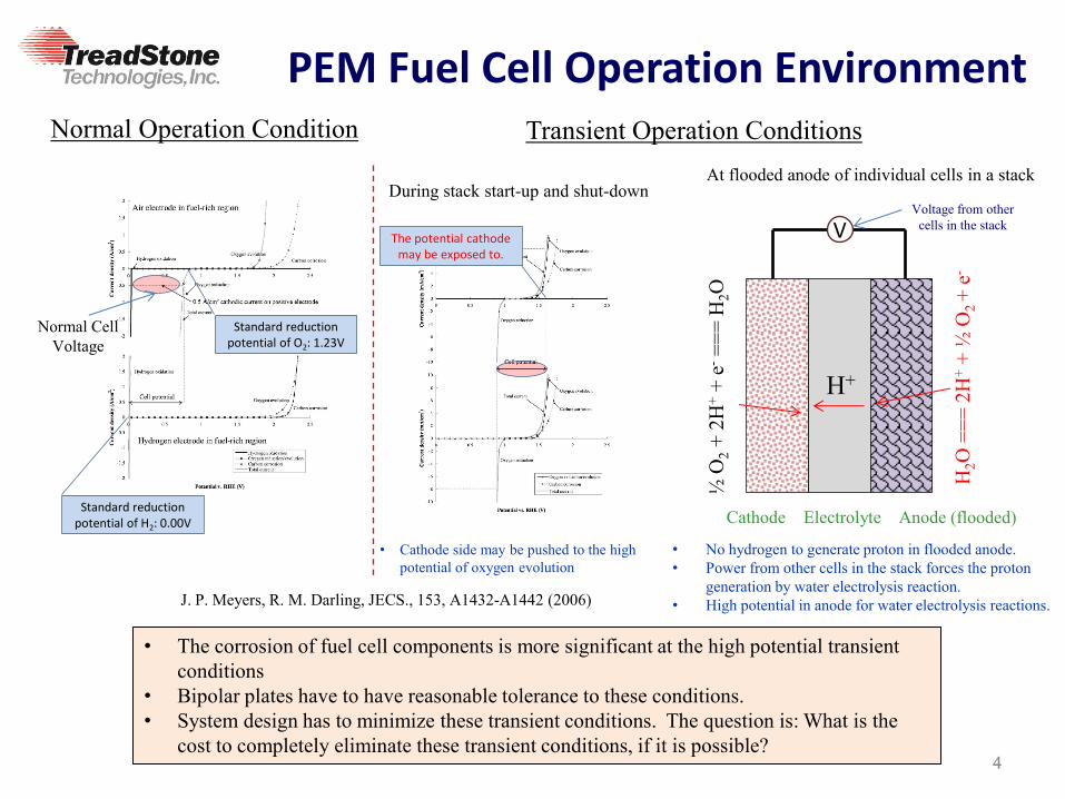
PEM Fuel Cell Operation Environment
4
Normal Operation Condition
• The corrosion of fuel cell components is more significant at the high potential transient conditions
• Bipolar plates have to have reasonable tolerance to these conditions. • System design has to minimize these transient conditions. The question is: What is the
cost to completely eliminate these transient conditions, if it is possible?
Transient Operation Conditions
• Cathode side may be pushed to the high potential of oxygen evolution
J. P. Meyers, R. M. Darling, JECS., 153, A1432-A1442 (2006)
Standard reduction potential of O2: 1.23V
Standard reduction potential of H2: 0.00V
Normal Cell Voltage
During stack start-up and shut-down At flooded anode of individual cells in a stack
½ O
2 + 2
H+ +
e- =
== H
2O
H2O
===
2H
+ + ½
O2 +
e-
H+
Cathode Electrolyte Anode (flooded)
V Voltage from other
cells in the stack The potential cathode
may be exposed to.
• No hydrogen to generate proton in flooded anode. • Power from other cells in the stack forces the proton
generation by water electrolysis reaction. • High potential in anode for water electrolysis reactions.

5
TreadStone’s Coating with Precious Metals --- Dotted Metal Plate Technologies
Highly conductive small dots can ensure the sufficient low electrical contact resistance of the metal plates for
electrochemical applications
5
Electrical Resistivity Graphite: 1375 .cm Gold: 2.2 .cm
Design Feature: 1. Using a small amount of electrically conductive
and corrosion resistant material to cover a small portion of the substrate surface in the form of isolated vias (dots).
• Low cost 2. Using non-conductive (or poor conductive)
material to cover the rest of the substrate surface and separate conductive vias.
• Eliminate galvanic corrosion • Easy processing
Substrate Metal
ElectricalPathway
Corrosion resistant alloy w/ a poor conductive surface layer
Electrically conductive dots

Actual Contact between GDL and Metal Plate
6
In micro scale, the GDL only in contact with metal plates at high points, of the rough surface of plates.
SS Plate
GDL Fiber
Gold Coated SS Surface
Majority of gold coated surface are not in contact with GDL.
On plates with gold dots on the surface: dots can standout out of the rough surface SS plate that have more chances to be contact with GDL.
GDL Fiber
Gold Dots on SS Surface SS Plate
Large amount of small gold dots can maintain sufficient contact points for low contact resistance.
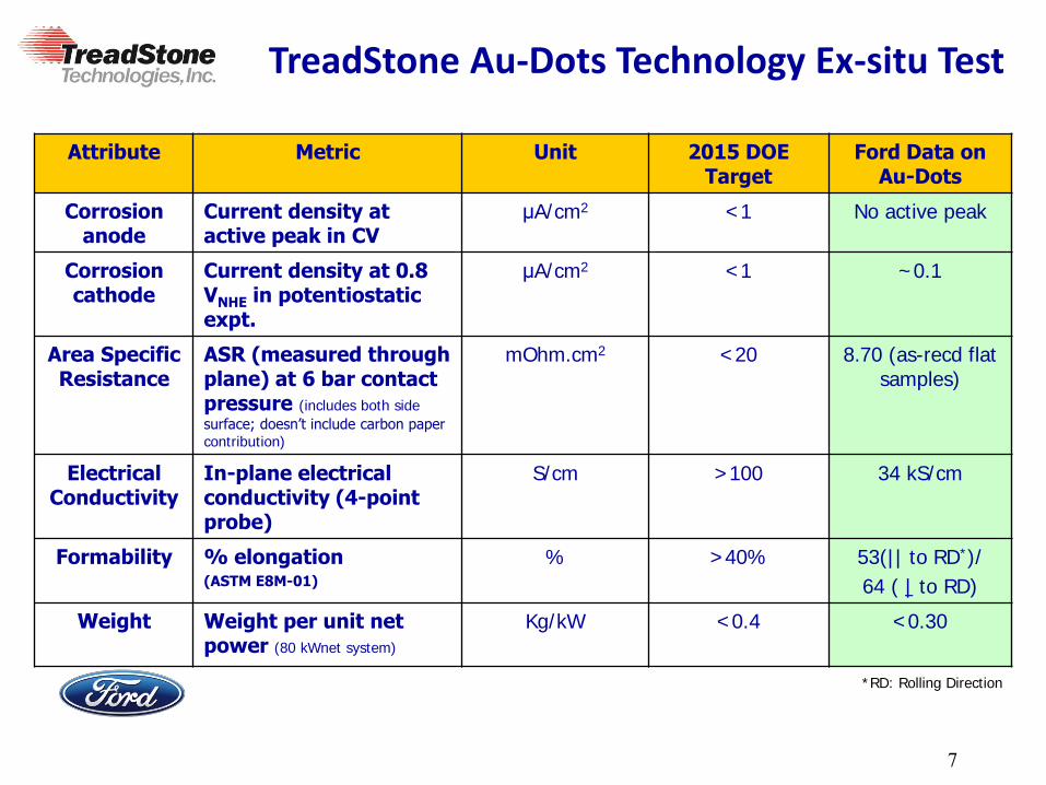
TreadStone Au-Dots Technology Ex-situ Test
Attribute Metric Unit 2015 DOE Target
Ford Data on Au-Dots
Corrosion anode
Current density at active peak in CV
μA/cm2 <1 No active peak
Corrosion cathode
Current density at 0.8 VNHE in potentiostatic expt.
μA/cm2
<1 ~0.1
Area Specific Resistance
ASR (measured through plane) at 6 bar contact pressure (includes both side
surface; doesn’t include carbon paper contribution)
mOhm.cm2 <20 8.70 (as-recd flat samples)
Electrical Conductivity
In-plane electrical conductivity (4-point probe)
S/cm >100 34 kS/cm
Formability % elongation (ASTM E8M-01)
% >40% 53(|| to RD*)/
64 ( | to RD)
Weight
Weight per unit net power (80 kWnet system)
Kg/kW
<0.4
<0.30
*RD: Rolling Direction
7

8
20-cell Stack Test at Ford
8
Contact Resistance [mΩ.cm2]
TreadStone Au-dot Plate Durability Test on 316L MP3 MBPP
Plate # #18 #19 #17 #16 Average of all plates
Testing Time (hrs.) 500 1000 1500 2000 500-2000
TPV (mV) BOL 9.09 8.49 7.42 8.12 8.41
MOL 5.90 7.21 5.93 5.67 6.40
Au splats on 1000 hrs. tested plate
In Channel
On Land
Au splat pressed flatter in the stack, lead to the lower
contact resistance.

9
TreadStone’s Coating without Precious Metals --- Doped TiOx Coating
Doping TiO2 with +5 valence elements will enforce the formation of Ti+3 in TiO2 lattice structure, and result in higher electronic conductivities.
Electron hopping between Ti+3 & Ti+4 sites
Challenges to use doped TiOx coating: 1. Doped TiOx is semi-conductive. The
electrical conductivity is not high enough. 2. How to obtain reliable bonding of doped TiOx
on metal substrate surface.
TreadStone’s approach: To coat stainless steel substrate with Ti-Nb or
Ti-Ta alloy. Then, grow the doped TiOx surface layer on the Ti alloy coating layer.
1. The doped TiOx on Ti alloy surface is thin and reliable.
2. Ti alloy bonding layer has excellent adhesion on metal substrate.
Doped TiOx semi-conductive surface layer
Ti alloy bonding layer
SS Substrate Layer
A. Trenczek-Zajac, M. Rekas, Materials Science-Poland, Vol. 24,
No. 1, 2006
Electrical conductance of Nb2O5 doped TiOx
TreadStone’s Coating Structure

10
ex-situ Tests of Doped TiOx coated SS
in pH 3 H2SO4 + 0.1 ppm HF at 80oC
Potentiodynamic Test (@10 mV/min) Potentiostatic Test (@0.8VNHE)
0 0.5 1.010-10
10-9
10-8
10-7
10-6
10-5
10-4
10-3
E (Volts)
I (Am
ps/c
m2 )
35-88-1 Ti-2Nb-SS HF 300C.cor35-88-2 Ti-2Ta-SS HF 300C 2nd sample.cor
Nb-TiOx Coated SSTa-TiOx Coated SS
E Ag/AgCl (Volt)
• Both Nb and Ta doped TiOx coated SS can meet the corrosion current target (<1 A/cm2) • Ta-TiOx coated SS has lower corrosion current than that of Nb-TiOx
0.00
0.02
0.04
0.06
0.08
0.10
0.12
0.14
0.16
0.18
0.20
0 50 100
Cu
rre
nt
A
/cm
2
Time hours
Nb-TiOx coated SS
Ta-TiOx coated SS

11
Doped TiOx Coating Stability Test in Extreme Conditions
• Doped TiOx coated SS has low surface electrical contact resistance.
• The coated SS has superior corrosion resistance for PEM fuel cell applications.
• The extreme corrosion condition (@ 1.6VNHE or 2 VNHE) ex-situ tests are not included in regular standard, but it is very attractive to OEMs because of the concerns of stack transient operation conditions.
in pH 3 H2SO4 + 0.1 ppm HF at 80oC
316L SS with Nb-TiOx coating before and after corrosion tests
316L SS with Ta-TiOx coating before and after corrosion tests
0.00
5.00
10.00
15.00
20.00
25.00
0 100 200 300 400
TPR
m
.cm
2
Compression Pressure psi
Nb-TiOx coated SSbefore corrosionafter 0.8V 100 hr
after 1.6V 24 hr
after 2.0V 24 hr
0.00
5.00
10.00
15.00
20.00
25.00
0 100 200 300 400
TPR
m
.cm
2
Compression Pressure psi
Ta-TiOx coated SSbefore corrosion
after 2V 24 hrs

12
In-situ Cell/stack Test with Nb Doped TiOx Coated SS Plates
Contact Resistance with GDL before and after 1,100 hrs. single cell test at consistent current
0
10
20
30
40
50
60
70
0 50 100 150 200 250 300TP
R
m
.cm
2
Pressure psi
525 hrs
BOT
Through Plate Resistance with GDL before and after 525 hrs. 10-cell stack test at dynamic testing condition

13
Summary
13
• TreadStone has developed low cost coating technologies for PEM fuel cell and electrolyzer applications. DOTS technology has been thoroughly evaluated in PEM fuel cell and
electrolyzer stacks. It is ready for commercialization.
TIOX technology has demonstrated superior corrosion resistance. Further development is focused on the manufacturing process and scientific mechanism investigation.
• Further technology development for commercialization: Roll to roll coating process for low cost manufacturing.
• The corrosion resistant coating must be capable to withhold the physical impact and substrate deformation during plate stamping.
• Plate joining (welding) technology has to be compatible with the coating.
High production yield in continuous production.
Minimum capital investment for early market penetration.

14
Acknowledgement
• Department of Energy • Ford Motor Company • Hawaii Natural Energy Institute,
University of Hawaii
14