corporation robots saleh faraj mansour a thesis
TRANSCRIPT

CORPORATION ROBOTS
SALEH FARAJ MANSOUR
A thesis submitted in fulfillment of the requirement for the award of the
Degree of Master of Electrical Engineering
Faculty of Electrical and Electronic Engineering
University Tun Hussein Onn Malaysia
MAY 2011

V
ABSTRACT
Nowadays, various robots are built to perform multiple tasks. Multiple robots working
together to perform a single task becomes important. One of the key elements for multiple
robots to work together is the robot need to able to follow another robot. This project is
mainly concerned on the design and construction of the robots that can follow line. In this
project, focuses on building line following robots leader and slave. Both of these robots will
follow the line and carry load. A Single robot has a limitation on handle load capacity such as
cannot handle heavy load and cannot handle long size load. To overcome this limitation an
easier way is to have a groups of mobile robots working together to accomplish an aim that
no single robot can do alone.

VI
ABSTRAK
Saat ini, pelbagai robot dibuat untuk menjalankan banyak tugas. Beberapa robot bekerja sama
untuk melakukan satu tugas menjadi penting. Salah satu elemen kunci untuk robot ganda untuk
bekerja sama adalah keperluan robot untuk bisa mengikuti robot lain. Projek ini terutama
berkaitan pada reka bentuk dan pembinaan robot yang dapat mengikuti garis. Dalam projek ini,
menumpukan pada pembangunan baris berikut pemimpin robot dan budak. Kedua-dua robot
akan mengikuti garis dan membawa beban. Sebuah robot tunggal mempunyai had-had dalam
menangani kapasiti beban seperti tidak dapat menangani beban berat dan tidak boleh menangani
beban saiz panjang. Untuk mengatasi keterbatasan ini cara yang lebih mudah adalah memiliki
kumpulan robot mobile bekerja sama untuk mencapai suatu tujuan bahawa tidak ada satu robot
boleh melakukannya sendiri.

VII
CONTENTS
TITLE I
DECLARATION II
DEDICATION III
ACKNOWLEDGEMENT IV
ABSTRACT V
ABSTRAK VI
CONTENTS VII
LIST OF TABLES X
LIST OF FIGURES XI
LIST OF SYMBOLS XIII
LIST OF APPENDIX XIV
CHAPTER 1 INTRODUCTION 1
1.1 Introduction 1
1.2 Problem Statement 3
1.3 Objectives 4
1.4 Scope of project 4
1.5 Organization of project 4
VIII
CHAPTER 2 LITERATURE REVIEW 6
2.1 Introduction 6
2.2 Development of Road Vehicle Convoy System 6
2.3 Low Cost Sensing for Autonomous Car Driving on
Road
7
2.4 Leader/Follower Behaviour using Ultrasonic
transmitter and receiver
9
2.5 Scale Invariant Feature Transform (SIFT)
algorithm
10
2.6 The X80 Robot 12
2.7 Raccoon 13
CHAPTER 3 METHADOLOGY 15
3.1 Introduction 15
3.2 Project procedures 15
3.3 Design process 17
3.4 Design Prototype 18
3.4.1 Control system 18
3.4.2 The Sensor 19
3.4.3 The comparator and sensor circuit 21
3.4.4 The Processor Unit 22
3.4.5 Motor driver 25
3.4.6 DC motor: 27
3.4.7 Wheels 28
3.4.8 LM7805 Voltage Regulator 29
3.4.9 Programming 30
CHAPTER 4 RESULT AND DISCUSSION 34
4.1 Introduction 34
4.2 Testing the Motor Circuit 34
4.3 Motor Circuit Analysis 36

IX
4.4 Output Waveform 37
4.5 Mode of movement 38
4.6 Final result for line following robots carrying load 40
CHAPTER 5 CONCLUSION AND RECOMMENDATION 42
5.1 Conclusion 42
5.2 Recommendation 43
REFFERENCE 44
APPENDIX 46

X
LIST OF TABLES
3.1 sensor arrays
Declaration of ports
19
3.2 31
4.1 Motor circuit testing of line following robot 35
4.2 Motor Circuit Measurement voltage when follow white line 36
4.3 Motor Circuit Measurement voltage when follow black line 37

XI
LIST OF FIGURES
1.1 Block diagram of mobile robot 3
2.1 HANS Vehicle 7
2.2 Occupancy Grid 9
2.3 Maxelbot 10
2.4 Robot Follower Using SIFT Algorithm 11
2.5 X80 ROBOT 12
2.6 IR sensor on X80 robot 12
3.1 Overall of the project 16
3.2 Flowchart of design process 17
3.3 block diagram of line following system 18
3.4 The basic design of IR sensor 20
3.5 infrared reflection 21
3.6 schematic of comparator and IR sensor circuit 22
3.7 Microprocessor Unit 24
3.8 PIC16F877A 25
3.9 driver motor MD30B 26
3.10 Flux magnet 27
3.11 DC motor 28
3.12 The motor and caster placed on robot 29
3.13 LM7805 30

XII
3.14 Flow chat of control program 32
3.15 Flow chart of line following robots 33
4.1 Waveform of output voltage at the motor driver when
moving forward
38
4.2 Flow Chart of programming Development for line following
robot
39
4.3 The Two Line following Robots carrying the load 40
4.4 line following robots turn left and carrying load 41
4.5 line following robots turn right and carry the load 41

XIII
LIST OF SYMBOLS
V - Voltage
+ - Positive
- - Negative
I - Input
O - Output
ICP - In-circuit debugger
CCP - Capture - compare
PWM - Pulse – width modulation
PSP - Parallel slave port
RPM - Rotation per minute
IR - Infra red

XIV
LIST OF APPENDIXS
A Coding code of line following robots 46
B PIC16F877A & MD30B motor driver data sheet 61

CHAPTER 1
1.1 Introduction
Mobile robots are becoming more heavily used in environments where human
involvement is limited, impossible, or dangerous. These robots perform some of the
more dangerous and laborious human tasks on Earth and throughout the solar system,
many times with greater efficiency and accuracy, saving both time and resources. There
exists a Nomad robot used to do all mission in Mars. This mobile robot is a nice
application for having new knowledge in the space, but the inversion it is very expense
and very complex in design: It requires several capabilities to operate in many
environments. The cost was over 1.6 million dollars. If it has problem or fail, all the
work will stop. An easier and cheaper way, is to have a groups of mobile robots working
together to accomplish an aim that no simple robot can do alone. An ideal application
for groups of heterogeneous robots working together, like a society of insect, can
accomplish the same mission that one robot. Using simpler mobile robots doing specific
task, is less expensive, more reliable and it can reach the same aims of one robots. Some
examples of applications are in manufacturing, medicine, space exploration and home.
The nature of work environments requires the robotic systems be fully autonomously in
achieving human supplied goals. One approach to designing these autonomous systems
is to develop a single robot that can accomplish particular goals in a given environment.
The complexity of many environments or works may require a mixture of robotic
capabilities that is too expensive to design into a single robot. Additionally, time
constraints may require the use of multiple robots working simultaneously on different
aspects of the mission in order to successfully accomplish the objective. In cases, it may
be easier and cheaper to design cooperative teams of robots to perform the same tasks

2
than it would be to use a single robot. Then, it is possible to build teams of
heterogeneous robots that can work together to accomplish a mission, where each robot
has different architecture performing different task in a collaborative manner. Any of
this group of robots needs reliable communication among them, in such way that the
robots will be able to accomplish their mission even when no robot failures occur. The
multi robot system required some knowledge of capabilities of its team-mates, before the
start of the mission. The team of robots can be model observing the natural behavior of
insects. They form colonies with individuals that perform different roles in function of
the needing of the community. Using this model, it is possible to have colony of robots
with some robots in charge of some responsibilities to work with others in a cooperative
way to do same tasks, in a collaborative way, to communicate each other to be more
efficient or to take decisions in a collective way, etc. in the same form as natural insects.
This colony has to have “nest” where the some robot assigns to others what to do, and
other robot that receive orders from human and communicate him the results. It is
necessary to formulate, describe, decompose, and allocate problems among a group of
intelligent agents; to communicate and interact; to act coherently in actions; and to
recognize and reconcile conflicts. In this presentation is focusing in colony of robots.
This implies to merge several disciplines such as mobile robotics, intelligent agents,
ontologisms, semantics, as well as automatic control, models of communities,
communication, and others ones, to have control of a society of robots working together
in a collaborative and cooperative way in a non structured environments [1] . Design and
construction of Mobile Robot requires a broad range of engineering skills such as
electronics design, mechanical design, program design and how the student approach
complex engineering problem. To build this project we need know how to build the
sensor circuit, comparator circuit, controller circuit and motor driver circuit then we
connect them together as showing in Figure 1.1

3
Figure 1.1: Block diagram of mobile robot
A mobile robot is divided into two main parts, namely the software and
hardware. For the software, PIC16F877A micro controller will be use for system
controller for this robot. While on the hardware side, a circuit will be built and
connected to sensors and motors. For this project a better of reflective sensor is to use
Infrared Light (IR) and NPN transistor, as less much interferences. The control has 6
modes of operation, turn left/right, forward/reverse, and stop. The actual action is caused
by controlling the direction/speed of the two motors (the two back wheels), thus causing.
Two motors as an output will control by motor driver that connected to the PIC16F877A
1.2 Problem statement
A Single robot has a limitation on handle load capacity such as cannot handle heavy load
and cannot handle long size load. To overcome this limitation an easier way is to have a
groups of mobile robots working together to accomplish an aim that no single robot can
do alone. The problem statement of this project is how to develop corporation robots.

4
1.3 Objectives
In this master project the objectives divided into:
1- To design single line following robot as leader.
2- To design second line following robot as slave robot.
3- To develop a programming code suitable for both robots to follow the line.
1.4 Scope of project
Scope of this project proposal is:
1- Develop two following line robots. In which the first robot as leader and the second
robot as slave.
2- The robots controller developed by using PIC16F877A microcontroller that is
program with assembly language.
3- Use DC motors as actuators with suitable motor driver.
1.5 Organization of project
Chapter one: Discuses the introduction (problem statement, Objectives, Scope of
project and Organization of project)
Chapter two: Discuses the literature Review

5
Chapter three: Discuses the methodology
Chapter four: Concluding the results and Discussion
Chapter five: Conclusion and recommendations

CHAPTER 2
LITERATURE REVIEW
2.1 Introduction
This chapter reviews some of previous work on development of single and corporation
robots.
2.2 Development of road vehicle convoy system
A final year project entitled “Development of a road vehicle model for road vehicle
convoy system” [2] was conducted at Faculty Electrical Engineering (FKE), University
Technology Malaysia in 2007. In this project, two small scale car-like robots were
developed. One is the leading vehicle and another is the following vehicle. The
following vehicle could follow the leading vehicle in straight line.

7
Both vehicles in this project utilize PIC 18F454 microcontroller (MCU) as the “brain”
for both vehicles. The following vehicle utilizes ultrasonic sensor (R40-16 & T40-16) to
detect and measure the distance between the leading and the following vehicle. When
the ultrasonic sensor sends a wave with certain frequency and received it back through
reflection after hit the obstacle, the information was sent to the PIC microcontroller. The
Microcontroller then perform calculation to obtain the distance between the vehicles and
follow the vehicle. The C programming language was used for the programming part in
this project. The MPLAB IDE version 7.43 with C18 compiler support C language
programming.
The robot follower in [2] has a numbers of limitations. Firstly, the following
vehicle cannot follow the leading vehicle when the leading vehicle turn left or right from
the straight line. Besides, the following vehicle could not avoid any obstacle or collision.
The following vehicle also could not vary its speed in accordance to the distance
between the vehicles. It can travel at a constant speed only.
2.3 Low Cost Sensing for Autonomous Car Driving on Road
Figure 2.1 HANS Vehicle

8
According to [3], a car-like robot equipped with a system called HANS, is able
to navigate in an autonomous and safe manner, performing trajectories similar to the
ones carried out by human drivers. The system was successfully tested in both
simulations and in a laboratory environment using a mobile robot to emulate the carlike
vehicle. As a result, this autonomous car can follow the front vehicle in curve road.
Besides, this mobile robot also can follow the road, keeping the car in the right lane,
maintaining safe distances between vehicles, and avoiding collision. For this mobile
robot, it is assumed that there are no cars driving faster than the HANS vehicle which
means that no cars will appear from behind.
HANS in [3] uses a low resolution web camera located in the centre of the
vehicle behind the rear-view mirror and a set of sixteen sonar sensor. The key role of the
camera is to act as a vision system. It is used to detect the side lines that bound the
traffic lanes, the position and orientation of the robot relative to these lines, and the
vehicles driving ahead and determining their lane and distance to the robot.
The sixteen sonar sensor was arranged to build up a occupancy grid as shown in
figure 2.2. This strategy is to reduce the influence of sonar reflections. Each sonar sensor
will form up one cone and each cone is divided into zones. The distance of each zone is
defined from the robot. Obstacles lying over a region of the occupancy grid contribute to
the voting of the cells. The zone with the highest number of measurements (votes in a
sense) is considered as being occupied by obstacle. Sonar sensors are also used to detect
emergency stopping conditions. With combinational of camera and sonar sensor, the
perception of environment also can be mapped for the robot making autonomous
decision.

9
Figure 2.2: Occupancy Grid
2.4 Leader/Follower Behavior using ultrasonic transmitter and receiver
Figure 2.3 shows two robots that are performing the leader and follower behavior. The
robot is called Maxelbot [4]. In figure 2.3, one of the robots acts as the leader and
another robot act as follower in the following behavior. The leader uses the ultrasonic
transmitter to transmit a signal through the parabolic cone. The purpose of the parabolic
cone is to transmit the signal at 360 degree to the surrounding. The three receivers of the
following car will catch the signal transmitted from the transmitter. Then the following
car will perform mathematical calculation based on the distance of three receivers from
the transmitter. Base on the calculation result, the follower predicts the distance and
angle of leader relative to the follower.

10
Figure 2.3 : Maxelbot
Limitation of this project is that the effective distance that can be measured by
the follower from the leader is about one meter only. Once the distance of the leader is
more than 1 meter from the follower, the follower cannot follow the leader.
The advantage of this method is that the cost of the hardware is relatively low
when compared to the vision system base method. Beside, the robot is more robust when
performing the following task in multiple obstacles environment compared to following
system utilizing IR sensors only.
2.5 Scale Invariant Feature Transform (SIFT) algorithm
In [5], a robot was constructed to follow human or another robot using the vision system.
The vision system in this project utilized the SIFT algorithm as shown in figure 2.4. In
this algorithm, the robot uses the feature extracted from the training image of target to
track the target. Firstly, it uses the SIFT algorithm to recognize the target. After the

11
target is recognized, it estimates the position of the target. Then it uses the PID
controller to control the motor to maintain the minimum distance between the follower
and the target.
Figure 2.4: Robot Follower Using SIFT Algorithm
There are a number of limitations of this method for following behavior. The 3.5
meter effective distance for the recognition system is adequate for a small robots
operating indoors, but would not be adequate for larger outdoor platforms. Additionally,
direct pursuit of the leader’s current position is quite impropriate and does not work well
in complex environments. PID control loops were time consuming to properly tune, and
the performance of the simple robot platform limits the applicability of the system as
implemented to wider applications.
The advantages of this system are: Firstly, the immunity to orientation and
occlusion problems made the system easy to use. Object recognition also allows for the
implementation of a wide variety of different behaviors based upon a set of different

12
trained objects, opening the way for new avenues of human robot cooperation. And
despite the image recognition software iterating at only 2Hz, the controllers were able to
perform adequately for the task. With the application of increased processing power to
the problem, robot control performance would improve.
2.6 The X80 Robot
Figure 2.5 shows the image of the X80 robot. According to [6], the X80 robot has 4
Infrared sensors and 3 sonar sensors to perform the following task. It is used to pursuit
the direct position of leader robot. The position of each sensor is arranged as shown in
figure 2.6. The following task is heavily depending on the IR sensors only. The other 3
sonar sensors are used only to perform the checking on the measurement of distance
return by the IR sensors.
Figure 2.5: X80 ROBOT Figure 2.6 :IR sensor on X80 robot

13
The limitation of the robot is that this robot can only perform the following task
in free space. The follower will lost the target if it is operating in the space full of the
obstacles. Besides, it may also easily lost track of the leader robot. Another limitation is
that the follower robot needs to stop during turning direction when the leader robot turns
direction.
Despite its limitation, the X80 robot can follow the leader robot at low speed in
free space.
2.7 Raccoon
RACCOON is a vision-based system that tracks car taillights at night as
described in [7]. The RACCOON system was developed at Carnegie Mellon
University. The prototype was built and integrated with RACCOON system. This
system enables the autonomous vehicle to chase the leading car effectively under low
light condition.
According to [7], this project was inspired by following reason:
a) The road cannot be seen clearly at night.
b) Unlit landmarks cannot be detected so corners and intersections have to be
negotiated based solely on the observed actions of the lead vehicle at night.
Problems above make the following vehicle cannot detect the leading vehicle
clearly at night using normal vision system and algorithm. In normal algorithm, the
taillights can be easily extracted from a dark background. After the extraction, the
autonomous car steers toward the taillight of lead vehicle. The autonomous vehicle may
follow the lead vehicle successfully with this algorithm.
However, this algorithm fails when lead vehicles turns to follow winding road.
When this scenario occurs, the computer controlled may steer towards taillights of lead
vehicle and then results in corner cutting. These problems can be solved by using
RACCOON system.

14
Under RACCOON system autonomous car, the image sensor can build a global
map in real time that contains the position of lead vehicle based on the location and
separation of the taillights (taillights of car) in a sequence of video images. Only one
color camera was used as sensor. RACCOON is creating an intermediate map structure
which records the lead vehicle’s trajectory. The path is represented by points in a global
reference frame. After that, the Computer controlled vehicle is steered from point to
point to follow lead vehicle’s trajectory. The autonomous vehicles can follow the lead
vehicle at any desired speed to keep the lead vehicle’s taillights in sight. Using this
approach, the autonomous vehicle steers around corners and obstacles rather than
through them.

CHAPTER 3
METHADOLOGY
3.1 Introduction
This chapter explains the methods used to implement this project. The first one is to
identify and understand the flow of operation system. The project development consists
of two stages. The first stage is assembling the project. Meanwhile at the second stage is
troubleshooting and taken the data of each part of the project.
3.2 Project procedures
The procedure of the project as shown in figure 3.1 represented in the form of flow
chart. In the earlier stage, there will be a lot information gathering activities where
consists of many important information for the project. This project started by doing the
research with previous work which is related to the current project and understanding the
basic concept of the line following robot and also to obtain an idea of the progress that
has been achieved so far in the project.

16
Stage 1
………………………………………………………………………………………………………………………………………………………….
Stage 2
Figure 3.1: Overall of the project
Start
Select Title
Determine the objective and
scope
Literature Review
Finding
Information
Gather Information
for project
Store & arrange
information for
project report
Design & build
the project
Troubleshooting
Test /implement the project
Collect the data
Finish project
report
End

17
3.3 Design process
To develop a project, it will start by introducing a typical development cycle in the most general
terms. Then it will focuses on the particular aspects that pertain to the design of logic circuit. The
flowchart in figure 3.2 depicts a typical design process.
No
Yes
Yes
No No
Yes
Figure 3.2: Flowchart of design process
Required Product
Define specification
Initial design
Simulation
Prototype Implementation
Testing
Make correction
Redesign
Design correct?
Meets
specification
?
Finished product
Minor errors?

18
3.4 Design Prototype
This project consists several blocks such as:
1) Sensor
2) Comparator
3) Processor Unit
4) Motor Driver
Motor 1 Motor 2
Figure 3.3: block diagram of line following system
3.4.1 Control system
The electrical circuit of the project are compared the analog signal received from sensors
and then transmit the result to the processor in digit ,0, or ,1, and some of them send the
analog signals to the processor ought to convert them to digital form.
Sensor array Comparator
LM324
Microcontroller
PIC16F877A
Motor
Driver
Motor
Driver

19
3.4.2 The sensor
In this project, mobile robot uses 4 IR LEDs (Tx) and 4 IR sensors (Rx) with distance
between the two sensors is 15mm. the first Rx receives an analog signal that depends on
the intensity of light reflected by the black line of emitted beam by the Tx. These signals
are sent to the comparator LM324 with creates digital signals(0 or 1) that are sent to
microcontroller PIC.
Hence, the distance between sensors and ground surface is important and it is
more important than how to put sensors near each other. The distance between sensors
and ground surface must be 2 to 10mm and the distance between each sensor is depend
on the line width.
Mobil robot used four pair of sensors as shown in Table 1.
Table 3.1: sensor arrays
Tx1(left) Tx2(center) Tx3(center) Tx4(right)
Rx1(left) Rx2(center) Rx3(center) Rx4(right)
In this project the sensor will work as an input to microcontroller and the data
will be processing before microcontroller sending it to the output part which is motor
driver that will drive the dc motor. Infra red sensor (IR sensor) is a sensor that
compatible with the concept of mobile robots. This sensor is use to sure that the robot
will move in its own path by detect the line. IR reflectance sensors contain a matched
infrared transmitter and infrared receiver pair as shown in figure 3.5.

20
Figure 3.4 : The basic design of IR sensor
These devices work by measuring the amount of light that is reflected into the
receiver. Because the receiver also responds to ambient light, the device works best
when well shielded from ambient light, and when the distance between the sensor and
the reflective surface is small(less than 5 mm). IR reflectance sensors are often used to
detect white and black surface. White surface generally reflect well, white black surface
reflect poorly.
IR LED emits infrared radiation. This radiation illuminates the surface in front of
LED. Surface reflects the infrared light Depending on reflectivity of the surface, amount
of light reflected varies. This reflected light is made incident on reverse biased IR
sensor. When photons are incident on reverse biased junction of this diode, electron-hole
pairs are generated, which results in reverse leakage current. Amount of electron-hole
pairs generated depends on intensity of incident IR radiation. More intense radiation
results in more reverse leakage current. This current can be passed through a resistor so
as to get proportional voltage. Thus as intensity of incident rays varies, voltage across
resistor will vary accordingly [8]

21
Figure 3.5: infrared reflection
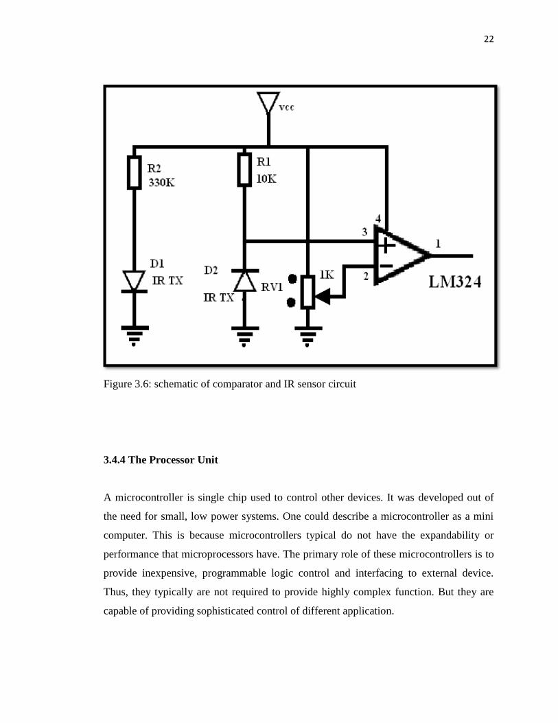
3.4.3 The comparator and sensor circuit
A comparator circuit compares two voltage signals and determines which one is greater.
The result of this comparison is indicated by the output voltage. If the op-amp’s output
is saturated in the positive direction, the no inverting input (+) is a greater, or more
positive, voltage than the inverting input (-), all voltages measured with respect to
ground. If the op-amp’s voltage is near the negative supply voltage (in this case, 0 volts,
or ground potential), it means the inverting input (-) has a greater voltage applied to it
than the no inverting input (+).
The received signals from the sensors are analog and converted to the digital
form. Therefore, the circuit can be designed to send the sensors signals to the processor,
directly. Hence, the processing time can be managed just by using an external
comparator. LM324 is a good comparator that is used in this project. One LM324 can
support four sensors.
22
Figure 3.6: schematic of comparator and IR sensor circuit
3.4.4 The Processor Unit
A microcontroller is single chip used to control other devices. It was developed out of
the need for small, low power systems. One could describe a microcontroller as a mini
computer. This is because microcontrollers typical do not have the expandability or
performance that microprocessors have. The primary role of these microcontrollers is to
provide inexpensive, programmable logic control and interfacing to external device.
Thus, they typically are not required to provide highly complex function. But they are
capable of providing sophisticated control of different application.

23
The microcontroller can provide, in a simplified form, all the main elements of
the conventional microprocessor system on one chip. As result, less complex
applications can be designed and built quickly and cheaply. A working system can
consist of microcontroller chip and just a few external components for feeding data in
and out, and generating the clock.
In this project, PIC16F877A was used as processor, PIC16f877A is a good flash
microcontroller that has many features a 40-pin and 5 input-output (I/O) ports. This flash
microcontroller may be programmed and erased instantly, without the need for a UV
light sours, to speed program testing. Reprogram ability offer a highly flexible solution
today’s ever- changing market demands, where product updates and modification are
routinely carried out in the field. Port A consists of 6 pins which can be set up as either
digital I/O or analog inputs. Port B is an 8 pin port which can be used for both digital I/O
operations and in-circuit debugger (ICD) operations. Port C, on the other hand, is a 5-pin
multi-functional port, which can be used for digital I/O, as capture-compare (CCP)
input, or pulse-width modulation (PWM) output.
Port D is an 8-pin port, which can be used for both digital I/O as well as parallel slave
port (PSP) functions. Finally, port E is a 3-pin port, which is used for external memory
connections.

24
Figure 3.7: Microprocessor Unit
The PIC16F877A microcontrollers carry a large memory array, which can be divided
into three types:
Flash program memory
EEPROM data memory
Data RAM

44
REFFERENCE
1- Colony of robots: New Challenge Workshop invited key lecture Gastón
Lefranc.2008
2- Gan Hui Wen. “Development of a road vehicle model for road vehicle convoy
System”, UTM 2007
3- Jo˜ao Sequeira, Andr´e Gonc¸alves, and Andr´e Godinho. Low cost Sensing For
Autonomous Car Driving In Highways. 2007.
4- Rozan Boudville. Obstacle detection and avoidance mobile robot. Universiti
Teknologi Malaysia. 2004.
5- J. Giesbrecht and DRDC Suffield. Leader/Follower Behaviour Using the SIFT
Algorithm for Object Recognition. 2006.

45
6- Adrian Korodi, Alexandru Codrean, Liviu Banita,Constantin Olosencu. Aspects
Regarding the Object Following Control Procedure for Wheeled Mobile Robots
2008.
7- Rahul Sukthankar. RACCOON: A Real-time Autonomous Car Chaser Operating
Optimally at Night. 2008
8- Omkar . “How to make simple infrared sensor modules “. February 19,2008 ,
From ”http://elecrom.wordpress.com/2008/02/19/how-to-make-simple-
infrared-sensor-modules/”