corp. 1801-l1 service literature revised 02/2021 el195uhne
TRANSCRIPT

Page 1© 2021 Lennox Industries Inc.
Litho U.S.A.
Corp. 1801-L1Revised 02/2021
EL195UHNEService Literature
EL195UHNE SERIES UNITS
EL195UHE series units are high-efficiency gas fur
naces available in heating input capacities of 40,000 to
100,000 Btuh and cooling applications from 2 through 5 tons.
Refer to Engineering Handbook for proper sizing.
Units are factory equipped for use with natural gas. All
EL195UHNE units are equipped with a hot surface igni
tion system. The gas valve is redundant to assure safety
shut-off as required by C.S.A.
The heat exchanger, burners and manifold assembly can be
removed for inspection and service. The maintenance section
gives a detailed description on how this is done.
All specifications are subject to change. Procedures outlined
in this manual are presented as a recommendation only
and do not supersede or replace local or state codes.
WARNINGElectric shock hazard. Can cause injuryor death. Before attempting to performany service or maintenance, turn theelectrical power to unit OFF at disconnect switch(es). Unit may have multiplepower supplies.
Table of Contents
Specifications 2. . . . . . . . . . . . . . . . . . . . . . . . . . . . . . . . .
Optional Accessories 3. . . . . . . . . . . . . . . . . . . . . . . . . .
Blower Performance Data 4. . . . . . . . . . . . . . . . . . . . . .
I-Unit Components 7. . . . . . . . . . . . . . . . . . . . . . . . . . . .
II Placement and Installation 17. . . . . . . . . . . . . . . . . . . .
III-Start-Up 37. . . . . . . . . . . . . . . . . . . . . . . . . . . . . . . . . . .
IV-Heating System Service Checks 38. . . . . . . . . . . . . .
V-Typical Operating Characteristics 44. . . . . . . . . . . . . .
VI-Maintenance 45. . . . . . . . . . . . . . . . . . . . . . . . . . . . . . .
VII-Sequence of Operation and Flow Charts 48. . . . . .
WARNINGImproper installation, adjustment, alteration, serviceor maintenance can cause property damage, personal injury or loss of life. Installation and service mustbe performed by a licensed professional HVAC installer (or equivalent), service agency or the gas supplier.
CAUTIONAs with any mechanical equipment, contact withsharp sheet metal edges can result in personal injury. Take care while handling this equipment andwear gloves and protective clothing.

Page 2
SPECIFICATIONSGas Heating Performance
Model No. EL195UH040NE36B EL195UH060NE36B1 AFUE 95% 95%
Input - Btuh 40,000 60,000Output - Btuh 39,000 58,000
Temperature rise range - °F 30 - 60 35 - 65Gas Manifold Pressure (in. w.g.)
Nat. Gas / LPG/Propane 3.5 3.5
High static - in. w.g. 0.5 0.5Energy Star® Certified Yes YesConnections in.
Intake / Exhaust Pipe (PVC) 2 / 2 2 / 2Gas pipe size IPS 1/2 1/2
Condensate Drain Trap (PVC pipe) - i.d. 3/4 3/4with furnished 90° street elbow 3/4 slip x 3/4 Mipt 3/4 slip x 3/4 Mipt
with field supplied (PVC coupling) - o.d. 3/4 slip x 3/4 MPT 3/4 slip x 3/4 MPTIndoor Blower
Wheel nom. dia. x width - in. 10 x 8 10 x 8Motor Type DC Brushless DC Brushless
Motor output - hp 1/2 1/2Tons of add-on cooling 1 - 2 1.5 - 3
Air Volume Range - cfm 260 - 990 550 - 1380Electrical Data Voltage 120 volts - 60 hertz - 1 phase
Blower motor full load amps 6.8 6.8Maximum overcurrent protection 15 15
Shipping Data lbs. - 1 package 122 128NOTE - Filters and provisions for mounting are not furnished and must be field provided.
1 Annual Fuel Utilization Efficiency based on DOE test procedures and according to FTC labeling regulations. Isolated combustion system rating for non-weatherized furnaces.
SPECIFICATIONSGas Heating Performance
Model No. EL195UH080NE48C EL195UH100NE60C1 AFUE 95% 95%
Input - Btuh 80,000 100,000Output - Btuh 78,000 97,000
Temperature rise range - °F 40 - 70 45 - 75Gas Manifold Pressure (in. w.g.)
Nat. Gas / LPG/Propane 3.5 3.5
High static - in. w.g. 0.5 0.5Energy Star® Certified Yes YesConnections in.
Intake / Exhaust Pipe (PVC) 2 / 2 2 / 2Gas pipe size IPS 1/2 1/2
Condensate Drain Trap (PVC pipe) - i.d. 3/4 3/4with furnished 90° street elbow 3/4 slip x 3/4 Mipt 3/4 slip x 3/4 Mipt
with field supplied (PVC coupling) - o.d. 3/4 slip x 3/4 MPT 3/4 slip x 3/4 MPTIndoor Blower
Wheel nom. dia. x width - in. 10 x 10 11-1/2 x 10Motor Type DC Brushless DC Brushless
Motor output - hp 3/4 1Tons of add-on cooling 2.5 - 4 3.5 - 5
Air Volume Range - cfm 760 - 1740 1260 - 2405Electrical Data Voltage 120 volts - 60 hertz - 1 phase
Blower motor full load amps 8.4 10.9Maximum overcurrent protection 15 15
Shipping Data lbs. - 1 package 148 157NOTE - Filters and provisions for mounting are not furnished and must be field provided.
1 Annual Fuel Utilization Efficiency based on DOE test procedures and according to FTC labeling regulations. Isolated combustion system rating for non-weatherized furnaces.

Page 3
OPTIONAL ACCESSORIES - ORDER SEPARATELYNOTE - FURNACES CANNOT BE TWINNED!
“B” Width Models
“C” Width Models
CABINET ACCESSORIESHorizontal Suspension Kit - Horizontal only 51W10 51W10Return Air Base - Upflow only 50W98 50W99High Performance Economizer (Commercial Only) 10U53 10U53CONDENSATE DRAIN KITSCondensate Drain Heat Cable 6 ft. 26K68 26K68
24 ft. 26K69 26K69Crawl Space Vent Drain Kit US 51W18 51W18
Canada 15Z70 15Z70CONTROLSBlower Relay Kit (for two-stage outdoor units) 85W66 85W66FILTER KITS1 Air Filter and Rack Kit
Horizontal (end) Size of filter - in. 87L96 - 18 x 25 x 1 87L97 - 20 x 25 x 1Side Return Single 44J22 44J22
Ten Pack 66K63 66K63Size of filter - in. 16 x 25 x 1 16 x 25 x 1
TERMINATION KITSSee Installation Instructions for specific venting information.Termination Kits - Direct Vent Applications Only
Concentric US - 2 in. 71M80 69M293 in. - - - 60L46
Canada - 2 in. 44W92 44W923 in. - - - 44W93
Flush-Mount US - 2, 2-1/2 or 3 in. 51W11 51W11Canada - 2, 2-1/2 or 3 in. 51W12 51W12
Wall - Close Couple
US - 2 in. 22G44 - - -3 in. 44J40 44J40
Wall - Close Couple WTK
Canada - 2 in. 30G28 - - -3 in. 81J20 81J20
Termination Kits - Direct or Non-Direct Vent
Roof 2 in. 15F75 15F75Wall Ring Kit 2 in. 15F74 3 15F74
Roof Termination Flashing Kit - Direct or Non-Direct Vent (2 flashings)
3 in. 44J41 44J41
1 Cleanable polyurethane frame type filter.2 Kits contain enough parts for two, non−direct vent installations.3 Non-direct vent only.NOTE - Termination Kits (44W92, 44W93, 30G28, 51W12, 51W19, 81J20) and Crawl Space Vent Drain Kit (15Z70) are certified to ULC S636 standard for use in Canada only.

Page 4
Blower Data
EL195UH040NE36B PERFORMANCE (Less Filter)External
Static Pressure in. w.g.
Air Volume / Watts at Various Blower SpeedsHigh Medium-High Medium Medium-Low Low
cfm Watts cfm Watts cfm Watts cfm Watts cfm Watts
0.00 1450 350 1280 247 1190 200 966 112 902 890.10 1429 360 1268 257 1171 207 939 119 875 990.20 1400 371 1248 267 1139 212 894 124 850 1100.30 1377 381 1222 279 1112 223 872 131 800 1140.40 1350 391 1195 286 1084 235 829 138 778 1220.50 1317 401 1156 298 1043 240 794 147 724 1290.60 1285 408 1127 308 1019 252 754 151 690 1420.70 1233 390 1107 316 987 259 708 161 633 1440.80 1160 370 1077 322 955 270 661 167 607 149
EL195UH060NE36B PERFORMANCE (Less Filter)External
Static Pressure in. w.g.
Air Volume / Watts at Various Blower SpeedsHigh Medium-High Medium Medium-Low Low
cfm Watts cfm Watts cfm Watts cfm Watts cfm Watts
0.00 1477 338 1289 240 1189 188 940 99 905 880.10 1431 353 1262 254 1160 200 918 109 873 970.20 1401 360 1244 263 1135 209 894 121 839 1080.30 1372 374 1215 270 1110 221 852 126 798 1130.40 1352 387 1189 282 1074 226 821 136 772 1230.50 1324 391 1165 292 1050 241 786 146 728 1300.60 1296 403 1130 302 1011 252 741 150 691 1400.70 1255 406 1102 313 988 258 703 161 641 1440.80 1190 386 1073 326 962 267 664 167 606 153
EL195UH080NE48C PERFORMANCE (Less Filter)External
Static Pressure in. w.g.
Air Volume / Watts at Various Blower SpeedsHigh Medium-High Medium Medium-Low Low
cfm Watts cfm Watts cfm Watts cfm Watts cfm Watts
0.00 1702 381 1502 270 1375 195 1298 169 1189 1320.10 1688 418 1479 287 1349 220 1258 187 1136 1440.20 1660 443 1450 304 1321 242 1215 203 1084 1580.30 1627 458 1403 321 1282 255 1172 215 1030 1720.40 1577 475 1370 337 1234 272 1131 231 990 1880.50 1540 483 1329 352 1191 288 1085 245 933 1950.60 1441 457 1291 369 1146 301 1045 259 883 2030.70 1293 402 1249 380 1102 315 992 271 830 2160.80 1144 365 1122 351 1053 326 951 285 809 219

Page 5
Blower Data
EL195UH100NE60C PERFORMANCE (Less Filter)
External Static
Pressure in. w.g.
Air Volume / Watts at Different Blower Speeds
Bottom Return Air, Side Return Air with Return Air from Both Sides or Return Air from Bottom and One Side.
Single Side Return Air − Air volumes in bold require Optional Return Air Base and field fabricated transition to accommodate 20 x 25 x 1 in. air filter in order to maintain proper air velocity.
High Med-High Medium Med-Low Low High Med-High Medium Med-Low Lowcfm Watts cfm Watts cfm Watts cfm Watts cfm Watts cfm Watts cfm Watts cfm Watts cfm Watts cfm Watts
0.00 2156 722 1922 497 1723 370 1589 215 1420 211 2102 118 1833 489 1688 170 1590 300 1375 2090.10 2112 738 1851 511 1681 388 1552 326 1380 227 2064 730 1809 504 1658 384 1540 314 1347 2240.20 2076 748 1808 533 1636 403 1525 334 1340 244 2038 749 1789 514 1623 402 1507 331 1325 2420.30 2035 768 1782 542 1604 425 1488 349 1290 259 2011 760 1761 531 1594 413 1472 348 1266 2460.40 2009 772 1749 558 1572 433 1441 362 1248 266 1968 770 1726 549 1561 431 1435 355 1247 2640.50 1942 776 1715 580 1533 452 1424 374 1213 281 1920 776 1685 560 1527 443 1394 374 1199 2780.60 1881 746 1681 584 1512 468 1357 382 1157 293 1849 741 1660 578 1489 455 1356 379 1154 2860.70 1790 715 1634 599 1459 474 1319 401 1136 306 1777 723 1622 593 1439 473 1317 395 1124 3010.80 1702 679 1582 613 1432 491 1300 418 1084 312 1682 681 1588 602 1407 488 1288 408 1067 308

Page 6
FIGURE 1
PARTS IDENTIFICATION
Ignition Control
Ignition Control
Gas Pipe Inlet(right side only)
Intake Air Pipe
Exhaust Pipe
Heat Exchanger
Burner Assembly
Inlet Air Assembly
Rollout Switch
Gas Valve
CombustionAir Inducer

Page 7
I-UNIT COMPONENTS
ELECTROSTATIC DISCHARGE (ESD)
Precautions and Procedures
CAUTIONElectrostatic discharge can affect electronic components. Take precautionsto neutralize electrostatic charge bytouching your hand and tools to metalprior to handling the control.
EL195UHNE unit components are shown in figure
NO TAG. The combustion air inducer, gas valve and burn
ers can be accessed by removing the outer access panel.
The blower and control box can be accessed by remov
ing the blower access panel.
A-Control Box Components (Figure 2)Unit transformer (T1) and integrated ignition control (A92)
are located in the control box. In addition, a door interlock
switch (S51) is located in the control box.
FIGURE 2
EL195UHNE Control Box
Integrated Control
Door InterlockSwitch
Transformer
Circuit Breaker
1. Transformer (T1)
A transformer located in the control box provides power to
the low voltage section of the unit. The transformers on all
models are rated at 40VA with a 120V primary and 24V
secondary.
2. Door Interlock Switch (S51)
A door interlock switch rated 14A at 120VAC is located on
the control box. The switch is wired in series with line volt
age. When the blower door is removed the unit will shut
down.
3. Circuit Breaker (CB8)
A 24V circuit breaker is also located in the control box. The
switch provides overcurrent protection to the transformer
(T1). The breaker is rated at 3A at 32V. If the current ex
ceeds this limit the breaker will trip and all unit operation will
shutdown. The breaker can be manually reset by pressing
the button on the face.
4. Integrated Ignition Control (A92)
WARNINGShock hazard.
Disconnect power before servicing. Control is notfield repairable. If control is inoperable, simply replace entire control.
Can cause injury or death. Unsafe operation will result if repair is attempted.
The hot surface ignition control system consisting of an in
tegrated control (figure 3 with control terminal designa
tions in tables 1, 2 and 3), sensor and ignitor (figure 5). The
integrated control and ignitor work in combination to en
sure furnace ignition and ignitor durability. The integrated
control, controls all major furnace operations. The inte
grated control also features a RED LED for troubleshoot
ing and two accessory terminals rated at (1) one amp. See
table 4 for troubleshooting diagnostic codes. The nitride
ignitor is made from a non-porous, high strength propri
etary ceramic material that provides long life and trouble
free maintenance.
TABLE 1
4-Pin Terminal Designation
PIN # FUNCTION
1 Combustion Air Inducer Line
2 Ignitor Line
3 Combustion Air Inducer Neutral
4 Ignitor Neutral
TABLE 2
12-Pin Terminal Designations
PIN # FUNCTION
1 High Limit Output
2 Not Used
3 24V Line
4 Not Used
5 Rollout Switch Out
6 24V Neutral
7 High Limit Input
8 Ground
9 Gas Valve Common
10 Pressure Switch In
11 Rollout Switch In
12 Gas Valve Out

Page 8
TABLE 3
1/4” QUICK CONNECT TERMINALS
120HUM Humidifier 120VAC
LINE 120VAC
XFMR Transformer 120VAC
CIRC Indoor blower 120VAC
EAC Indoor air quality accessory 120VAC
NEUTRALS Common 120VAC
HUM24 Humidifier 24VAC
3/16” QUICK CONNECT TERMINALS
COOL Cooling tap 24VAC
HEAT Heating tap 24VAC
FAN Continuous blower 24 VAC
PARK (no power) Park terminal for unused speed taps
FS Flame sense
24 COM Common 24VAC
TABLE 4
The integrated control is equipped with an LED light for troubleshooting. The diagnostic codes are listed below in table 4.
RED LEDFlash Code
Diagnostic Codes / Status of Furnace
Off No power to control or board fault detected
On Board fault detected,
Heartbeat1 Control powered - displayed during all modes of operation if no errors are detected
1 Reverse Line Voltage Polarity
2 Improper Earth Ground
3 Burner failed to light, or lost flame during heat demand
4 Low Flame Signal - check flame sensor
5 Watchguard - burner failed to light, exceeded maximum number of retries or recycles.
6 Not Used
7Primary or Secondary Limit Open or Watchguard Mode - Limit Switch Open longer than 3 minutes
8 Rollout Switch Open
9 Pressure Switch failed to close or opened during heat demand
10 Watchguard - Pressure Switch opened 5 times during one heat demand
11 Pressure Switch stuck closed prior to activation of combustion air inducer
12 Flame Sensed without gas valve energized
13 Low Line Voltage
Notes
Note 1 A ”Heartbeat” is indicated by a ”Slow Flash” - 1 sec on 1 sec off, repeating
NoteError codes are indicated by a ”Rapid Flash” - the LED flashes X times at 1/2 sec on 1/2 secoff, remains off for 3 sec, then repeats
NoteLast 10 error codes are stored in memory including when power is shut off to the unit. - To recall,press and release button, most recent will be displayed first, LED off for 3 sec, then next errorcode is displayed, etc. To clear error codes, depress and hold button longer than 5 seconds.

Page 9
FIGURE 3
INTEGRATED CONTROL(Automatic Hot Surface Ignition System)
BLOWER OFF DELAYRED LEDRECALL BUTTON
Electronic IgnitionOn a call for heat the integrated control monitors the com
bustion air inducer pressure switch. The control board will
not begin the heating cycle if the pressure switch is closed
(by-passed). Once the pressure switch is determined to be
open, the combustion air inducer is energized. When the
differential in the pressure switch is great enough, the pres
sure switch closes and a 15-second pre-purge begins. If
the pressure switch is not proven within 2-1/2 minutes, the
integrated control goes into Watchguard-Pressure Switch
mode for a 5-minute re-set period.
After the 15-second pre-purge period, the ignitor warms up
for 20 seconds during which the gas valve opens at 19 sec
onds for a 4-second trial for ignition. The ignitor remains
energized for the first 3 seconds during the 4 second trial. If
ignition is not proved during the 4-second period, the inte
grated control will try four more times with an inter purge
and warm-up time between trials of 35 seconds. After a to
tal of five trials for ignition (including the initial trial), the inte
grated control goes into Watchguard-Flame Failure mode.
After a 60-minute reset period, the integrated control will
begin the ignition sequence again.
Fan Time Control
Heating Fan On Time
The fan on time of 30 seconds is not adjustable.
Heating Fan Off Time
Fan off time (time that the blower operates after the heat
demand has been satisfied) can be adjusted by moving the
jumper to a different setting. The unit is shipped with a fac
tory fan off setting of 90 seconds. For customized comfort,
monitor the supply air temperature once the heat demand
is satisfied. Note the supply air temperature at the instant
the blower is de-energized.
Adjust the fan-off delay to achieve a supply air temperature
between 90° - 110° at the instant the blower is de-ener
gized. (Longer delay times allow for lower air temperature,
shorter delay times allow for higher air temperature). See
figure 4.
Cooling Fan On Time
The fan on time is 2 seconds and is not adjustable.
Cooling Fan Off Time
The control has a 45 second fan off delay after cooling de
mand has been met. This delay is factory set and not ad
justable.
HEAT FAN‐OFF TIME IN SECONDS
To adjust fan-off timing, reposition jumper across pins toachieve desired setting.
NO JUMPER
FIGURE 4
60
90
120
180 60
90
120
180 6
090
120
180 6
090
120
180
60 Second off Time
90 Second off Time
120 Second off Time
180 Second off Time

Page 10
FIGURE 5
HEATING COMPONENTS
Gas Valve
Primary Limit
Ignitor
Sensor
Gas Orifice
Air Orifice
Rollout Switch(location)
Air Gas Plenum
Gaskets
Burner
Heat Exchanger
Burner Box
B-Heating Components
Combustion air inducer (B6), primary limit control (S10), ig
nitor, burners, flame rollout switch (S47), gas valve (GV1),
combustion air pressure switch (S18), and heat exchangers
are located in the heating compartment. The heating
compartment can be accessed by removing the outer ac
cess panel.
1. Thermal Switch (Figure 5)
The auto-reset switch is located on the front of the air gas
intake. The switch will safely shut the unit down if excessive
temperatures are detected. When the switch senses ex
cessive temperature, the circuit breaks and the ignition
control immediately stops ignition and closes the gas
valve.
2. Burner and Orifice
Burners are factory set and require no adjustment. Always
operate the unit with air gas plenum in place. The burner
has one orifice located between the gas valve and the air
intake assembly (Figure 5). To check or replace the orifice
remove the black iron inlet pipe from the gas valve then re
move the four screws securing the gas valve to the intake
air pipe. The orifice is located in the orifice housing. The
burner uses an orifice (see Table 16) that is precisely
matched to the burner input. The burner can be removed
for service. If burner has been removed, it is critical to re
place all gaskets.
TABLE 5Orifice Size
Unit Input Nat Orifice Size (0 - 7500 ft)
040 0.0472
060 0.0595
080 0.0689
100 0.0810

Page 11
3. Primary Limit Control
The primary limit (S10) is located in the heating vestibule
panel. When excess heat is sensed in the heat exchanger,
the limit will open. If the limit is open, the furnace control en
ergizes the supply air blower and closes the gas valve. The
limit automatically resets when unit temperature returns to
normal. The switch must reset within three minutes or the
SureLight control will go into Watch guard for one hour. The
switch is factory set and cannot be adjusted. The switch
may have a different set point for each unit model number.
See Lennox Repair Parts Handbook if limit switch must be
replaced.
4. Gas Valve (Figure 6)
The EL195UHNE uses an internally redundant valve to assure
safety shut‐off. If the gas valve must be replaced, the same
type valve must be used.
24VAC terminals and gas control switch are located on
top of the valve. All terminals on the gas valve are con
nected to wires from the ignition control. 24V applied to the
terminals opens the valve.
Inlet and outlet pressure taps are located on the valve. A
manifold adjustment screw is also located on the valve. An
LP/Propane changeover kit is available.
FIGURE 6
NEGATIVE AIRPRESSURE PORT
POSITIVE AIRPRESSURE PORT
MANIFOLDPRESSURE TAP
INLETOUTLET
SUPPLYPRESSURE
TAP
GAS VALVE
5. Flame Sensor (Figure 5)
A flame sensor is located on the top of the air gas plenum.
The sensor can be removed for service without removing
the the burner. During operation, flame is sensed by cur
rent passed through the flame and sensing electrode. The
SureLight control allows the gas valve to remain open as
long as flame signal is sensed. To check flame sense signal
use the push-button found on the integrated control and go
to Field Test Mode. The menu will display the flame signal.
See table 6 for flame signal.
TABLE 6Flame Signal in Microamps
Normal Low Drop Out
2.6 or greater 2.5 or less 1.1
6. Ignitor (Figure 5)
EL195UHNE units use a nitride ignitor made from a propri
etary ceramic material. To check ignitor, measure its resist
ance and voltage. A value of 39 to 70 ohms indicates a
good ignitor. Voltage to the ignitor should be 102 - 132VAC.
See figure 7 for resistance and voltage checks.

Page 12
FIGURE 7
Ignitor Check Out(exploded view for clarity)
Test 1
Meter(set to ohms)
Remove 5-pin plug from controlCheck ohms reading across terminals 1and 5
Ohm value should be between 39 - 70.
Integrated control detail
.
Test 2
Seperate the 2-pin jack plug near the manifoldand check resistance of the ignitor. If the readingis correct, then then there is a problem with thewiring between the jack plug and control. If thereading is not correct the issue is the ignitor.
Meter(set to ohms)
Test 3
Insert meter probes into the terminals 1 and 5. (Use smalldiameter probes in order to not damage plug). Check
voltage during 20 second warm up period. Voltage shouldread 120 volts + 10%. If voltage is above these values,
check for correct supply voltage to furnace.
Integrated control detail
Integrated control detail
Meter(set to AC volts)

Page 13
7. Combustion Air Inducer (B6)& Cold End Header Box Figure 8
All EL195UHNE units use a combustion air inducer to
move air through the burners and heat exchanger during
heating operation. The blower uses a shaded pole
120VAC motor. The motor operates during all heating op
eration and is controlled by integrated control A92. Blower
operates continuously while there is a call for heat. The in
tegrated control will not proceed with the ignition sequence
until combustion air inducer operation is sensed by the prov
ing switches.
The combustion air inducer is installed on the cold end
header box. The cold end header box is a single piece
made of hard plastic. The box has an internal channel
where the combustion air inducer creates negative pres
sure at unit start up. The channel contains an orifice used
to regulate flow created by the combustion air inducer.
The box has pressure taps for the combustion air inducer
pressure switch hoses. The pressure switch measures
the pressure across the combustion air inducer orifice or
difference in the channel and the box. If replacement is
necessary the gaskets used to seal the box to the
vestibule panel and the combustion air inducer to
the box, must also be replaced.
8. Combustion Air Prove Switch Figure 8 and 9
EL195UHNE series units are equipped with a differen
tial pressure switch located on the cold end header box.
The switch monitors across the combustion air inducer orifice
to insure proper flow through the heat exchanger.
The switch is a SPST N.O. pressure switch electrically con
nected to the integrated control. The purpose of the switch is
to prevent burner operation if the combustion air inducer is not
moving enough air for proper combustion.
FIGURE 8
COMBUSTION AIR INDUCER AND PROVE SWITCH
Prove Switch
Combustion Air Inducer
FIGURE 9
Pressure Switch
On start‐up, the switch monitors whether the combustion air
inducer is operating. It closes a circuit to the integrated
control when the difference in pressure across the com
bustion air inducer orifice exceeds a non-adjustable factory
setting. If the switch does not successfully sense the re
quired differential, the switch cannot close and the fur
nace cannot operate. If the flue or air inlet become ob
structed during operation, the switch senses a loss of
pressure differential and opens the circuit to the integrated
control. If the condensate line is blocked, water will back up
into the header box and reduce the pressure differential
across the switch. The pressure switch opens if the differ
ential drops below the set point. See table 7.
TABLE 7
Unit Set Point
-040
0.50“-060
-080
-100

Page 14
C- Blower Compartment
IMPORTANTEach blower is statically and dynamically balancedas an assembly before installation in the unit.
ML195UHE units are equipped with a constant torque ECM
motor. It has a DC motor coupled to an electronic control
module both contained in the same motor housing. The mo
tor is programmed to provide constant torque at each of the
five selectable speed taps. Each tap requires 24 volts to en
ergize.
Input Voltage Requirements
The circuit is designed to be operated with AC voltage. To
enable a tap requires 12 to 33VAC. Expected current draw
will be less than 20mA.
Troubleshooting the Motor
Troubleshooting the motor is an easy process. Follow
steps below.
1- Shut off power to unit.
2- Remove input plugs P48 and P49 from motor. See
figure 13 for troubleshooting procedure.
If correct voltage is present in tests 1 and 2 and motor is not
operating properly, replace motor. The motor is not field re
pairable.
If replacing the indoor blower motor or blower wheel is nec
essary, placement is critical. The blower wheel must be cen
tered in the blower housing as shown in figure 10. When re
placing the indoor blower motor the set screw must be
aligned and tightened with the motor shaft as shown in figure
11.
FIGURE 10
Center Blower Wheelin Blower Housing
BLOWER WHEEL REPLACEMENT
FIGURE 11
Set ScrewHousing Hub
ALIGN AND TIGHTEN SET SCREW WITHFLAT SIDE OF MOTOR SHAFT
MotorShaft
FIGURE 12
SECONDARY LIMIT CONTROL
Secondary Limits

Page 15
12
34
5
CL
GN
Multi−Meter(set to VAC)
P48
P49
120
120
Turn on power to unit. Check for 120 volts across terminals“L” and “N” on input plug P48. If voltage is present continueto test 2. If voltage is not present problem may be may be upstream of plug P48 and proceed to test 3.
12
34
5
CL
GN
Multi−Meter(set to VAC)
P48
P49 24
Switch thermostat to CONTINUOUS FAN MODE. Check for24 volts across terminal “C” on input plug P48and speed tapused for continuous fan. (1, 2, 3, 4 or 5) on input plug P49. If24 volts is not present problem may be up stream of plug P49.Proceed to test 4.
Multi−Meter(set to VAC)
120
120
24
Multi−Meter(set to VAC)
Check for 24 volts across terminals “24 COM” and “FAN” terminals on the integrated control. If voltage is present, problem is with the harness. If voltage is not present problemmay be may be with the integrated control
Check for 120 volts across terminals “CIRC” and “Neutrals”on the integrated control. If voltage is present, problem iswith the harness. If voltage is not present problem may bemay be with the integrated control.
Test 1
Test 2
Test 3 (if necessary)
Test 4 (if necessary)
FIGURE 13

1234567
891011 12
1/16
TURN
Page 16
Replacing the Motor Module
1. Disconnect electrical power to unit.
2. Remove unit access panel.
3. Unplug the two harnesses from the motor control module. See figure 14.
TWO HARNESSCONNECTIONS
MOTOR CONTROL MODULE
MOTOR
FIGURE 14
Unplug the Two Harness Connection
4. Remove the two hex head bolts securing the motorcontrol module to the motor (see figure 15).
REMOVE BOTH HEXHEAD BOLTS
FIGURE 15
Remove the Hex Head Bolts
5. Slide the motor control module away from the motor toaccess and disconnect the internal three wire connector. It is not necessary to remove blower motor itself.Set both hex head bolts aside.
Testing the Motor (Figure16)
If any motor fails the below tests, do not install the new control module. The motor is defective and it also must be replaced. The new control can fail if placed on a defective motor.
1. Using an ohmmeter check the resistance from any oneof the motor connector pins to the aluminum end plateof the motor. This resistance should be greater than100k ohms.
2. Check the resistances between each of the three motor connector pins. These should all read approximately the same resistance within an ohm.
3. Check to see if the blower wheel spins freely.
FIGURE 16
Motor Test
TABLE 8
ScaleMeasurement range inwords
ohms
2 Mtwo megohm-two millionohms
0 - 2,000,000
200 Ktwo hundred kilo-ohm-twohundred thousand ohms
0 - 200,000
20 Ktwenty kilo-ohm-twentythousand ohms
0 - 20,000
2 Ktwo kilo-ohm two-thousandohms
0 - 2,000
200 two hundred ohms 0 - 200
Motor Module Installation
All replacement motor control modules look similar; however, each module is designed for a specific motor size. It isvery important to make sure that you are using the correctreplacement motor control module. USE OF THE WRONGMOTOR CONTROL MODULE MAY RESULT IN UNEXPECTED UNIT OPERATION.
1. Verify electrical power to unit is disconnected.
2. Connect three-wire harness from motor to controlmodule.
3. Mount new motor control moduleto motor using two hex head boltsremoved in figure 15. Torque boltsto 22 inch pounds or 1/16th clockturn as exampled to the right.
4. Reconnect the two harnesses tothe motor control module.
5. The electrical connectors of the motor should be facingdown to form a drip loop (figure17). This will directsmoisture away from the motor and its electric connections on the motor.
CONNECTORORIENTATION
BETWEEN 4 AND 8O'CLOCK
BACK OF CONTROLMODULE
DRIP LOOP
FIGURE 17
Drip Loop

Page 17
II-PLACEMENT AND INSTALLATION
Pipe & Fittings Specifications
All pipe, fittings, primer and solvent cement must conform
with American National Standard Institute and the Ameri
can Society for Testing and Materials (ANSI/ASTM) stan
dards. The solvent shall be free flowing and contain no
lumps, undissolved particles or any foreign matter that ad
versely affects the joint strength or chemical resistance of
the cement. The cement shall show no gelation, stratifica
tion, or separation that cannot be removed by stirring. Re
fer to the table 9 below for approved piping and fitting ma
terials.
CAUTIONSolvent cements for plastic pipe are flammable liquids and should be kept away from all sources ofignition. Do not use excessive amounts of solventcement when making joints. Good ventilation shouldbe maintained to reduce fire hazard and to minimizebreathing of solvent vapors. Avoid contact of cement with skin and eyes.
TABLE 9PIPING AND FITTINGS SPECIFICATIONS
Schedule 40 PVC (Pipe) D1785
Schedule 40 PVC (Cellular Core Pipe) F891
Schedule 40 PVC (Fittings) D2466
Schedule 40 CPVC (Pipe) F441
Schedule 40 CPVC (Fittings) F438
SDR-21 PVC or SDR-26 PVC (Pipe) D2241
SDR-21 CPVC or SDR-26 CPVC (Pipe) F442
Schedule 40 ABS Cellular Core DWV (Pipe) F628
Schedule 40 ABS (Pipe) D1527
Schedule 40 ABS (Fittings) D2468
ABS-DWV (Drain Waste & Vent)(Pipe & Fittings)
D2661
PVC-DWV (Drain Waste & Vent) Pipe & Fittings)
D2665
PRIMER & SOLVENT CEMENTASTM
SPECIFICATION
PVC & CPVC Primer F656
PVC Solvent Cement D2564
CPVC Solvent Cement F493
ABS Solvent Cement D2235
PVC/CPVC/ABS All Purpose Cement ForFittings & Pipe of the same material D2564, D2235, F493
ABS to PVC or CPVC Transition SolventCement D3138
CANADA PIPE & FITTING & SOLVENTCEMENT
MARKING
PVC & CPVC Pipe and Fittings
ULCS636PVC & CPVC Solvent Cement
ABS to PVC or CPVC Transition Cement
POLYPROPYLENE VENTING SYSTEM ULC-S636
PolyPro® by Duravent ULC-S636InnoFlue® by Centrotherm ULC-S636
IMPORTANTEL195UHNE exhaust and intake connections aremade of PVC. Use PVC primer and solvent cementwhen using PVC vent pipe. When using ABS ventpipe, use transitional solvent cement to make connections to the PVC fittings in the unit.
Use PVC primer and solvent cement or ABS solvent cement
meeting ASTM specifications, refer to Table 9. As an alter
nate, use all purpose cement, to bond ABS, PVC, or CPVC
pipe when using fittings and pipe made of the same materi
als. Use transition solvent cement when bonding ABS to ei
ther PVC or CPVC.
Low temperature solvent cement is recommended during
cooler weather. Metal or plastic strapping may be used for
vent pipe hangers. Uniformly apply a liberal coat of PVC
primer for PVC or use a clean dry cloth for ABS to clean in
side socket surface of fitting and male end of pipe to depth
of fitting socket.
Canadian Applications Only - Pipe, fittings, primer
and solvent cement used to vent (exhaust) this ap
pliance must be certified to ULC S636 and supplied by a
single manufacturer as part of an approved vent (ex
haust) system. In addition, the first three feet of vent
pipe from the furnace flue collar must be accessible for
inspection.
NOTE - The intake coupling on the furnace is ABS
material. Use transitional solvent to make connec
tions to PVC pipe.
NOTE - Exhaust coupling must be installed with pro
vided appliance adapter. See figure 20.

Page 18
TABLE 10OUTDOOR TERMINATION USAGE*
Input SizeVentPipe
Dia. in.
STANDARD CONCENTRIC
FlushMount
Kit
Wall Kit Wall Ring Kit
FieldFabricated
1-1/2 inch 2 inch 3 inch2 inch 3 inch 2 inch
51W11(US)
51W12(CA)
22G44 (US)430G28 (CA)
44J40 (US)
481J20 (CA)15F74
71M80(US)
444W92(CA)
69M29(US)
444W92(CA)
60L46 (US)444W93 (CA)
040
2 3YES YES 1YES 1YES 5YES 2YES
2-1/2 3YES YES 1YES 1YES 5YES 2YES
3 3YES YES 1YES 1YES 5YES 2YES
060
2 3YES YES 1YES 1YES 5YES 2YES
2-1/2 3YES YES 1YES 1YES 5YES 2YES
3 3YES YES 1YES 1YES 5YES 2YES
080
2 3YES YES YES 5YES YES YES
2-1/2 3YES YES YES 5YES YES YES
3 3YES YES YES 5YES YES YES
100
2 YES YES YES 5YES YES YES
2-1/2 YES YES 5YES YES YES
3 YES YES 5YES YES YES
NOTE - Standard Terminations do not include any vent pipe or elbows external to the structure. Any vent pipe or elbows external to the structure must be included in total vent lengthcalculations. See vent length tables.
* Kits must be properly installed according to kit instructions.1Requires field-provided outdoor 1-1/2” exhaust accelerator.2Concentric kits 71M80 and 44W92 include 1-1/2” outdoor accelerator, when used with 040 and 060 input models.3 Flush mount kits 51W11 and 51W12 includes 1-1/2 in. outdoor exhaust accelerator, required when used with 040, 060 and 080 input models.4 Termination kits 30G28, 44W92, 4493 and 81J20 are certified to ULC S636 for use in Canada only.5 See table 15 for vent accelerator requirements.
Joint Cementing Procedure
All cementing of joints should be done according to the
specifications outlined in ASTM D 2855.
DANGERDANGER OF EXPLOSION!
Fumes from PVC glue may ignite during systemcheck. Allow fumes to dissipate for at least 5 minutesbefore placing unit into operation.
1 - Measure and cut vent pipe to desired length.
2 - Debur and chamfer end of pipe, removing any ridgesor rough edges. If end is not chamfered, edge of pipemay remove cement from fitting socket and result in aleaking joint.
NOTE - Check the inside of vent pipe thoroughly for
any obstruction that may alter furnace operation.
3 - Clean and dry surfaces to be joined.
4 - Test fit joint and mark depth of fitting on outside of pipe.
5 - Uniformly apply a liberal coat of PVC primer for PVC oruse a clean dry cloth for ABS to clean inside socketsurface of fitting and male end of pipe to depth of fittingsocket.
NOTE - Time is critical at this stage. Do not allow primer to dry before applying cement.
6 - Promptly apply solvent cement to end of pipe and inside socket surface of fitting. Cement should be applied lightly but uniformly to inside of socket. Takecare to keep excess cement out of socket. Apply second coat to end of pipe.
7 - Immediately after applying last coat of cement to pipe,and while both inside socket surface and end of pipeare wet with cement, forcefully insert end of pipe intosocket until it bottoms out. Turn PVC pipe 1/4 turn during assembly (but not after pipe is fully inserted) to distribute cement evenly. DO NOT turn ABS or cellularcore pipe.
NOTE - Assembly should be completed within 20 seconds after last application of cement. Hammer blowsshould not be used when inserting pipe.
8 - After assembly, wipe excess cement from pipe at end
of fitting socket. A properly made joint will show a
bead around its entire perimeter. Any gaps may indi
cate an improper assembly due to insufficient sol
vent.
9 - Handle joints carefully until completely set.

Page 19
Venting Practices
FIGURE 18
* See table 9 for allowable pipe.
Piping Suspension Guidelines
NOTE - Isolate piping at the point where it exits the outside wall orroof in order to prevent transmission of vibration to the structure.
SCHEDULE 40PVC - 5'
all other pipe* - 3'
Wallinside outside
24” maximum3/4” minimum
Wall Thickness Guidelines
insulation(if required)
6. In areas where piping penetrates joists or interior
walls, hole must be large enough to allow clearance on
all sides of pipe through center of hole using a hanger.
7. When furnace is installed in a residence where unit is
shut down for an extended period of time, such as a
vacation home, make provisions for draining conden
sate collection trap and lines.
CHIMNEYOR GAS
VENT(Check sizing
for waterheater only)
FURNACE(Replacedby EL195)
WATERHEATER
OPENINGS(To Adjacent
Room)
If an EL195UHNE furnace replaces a furnace which was commonly vented with another gas appliance, the size of the existingvent pipe for that gas appliance must be checked. Without theheat of the original furnace flue products, the existing vent pipeis probably oversized for the single water heater or other appliance. The vent should be checked for proper draw with the remaining appliance.
FIGURE 19
REPLACING FURNACE THATWAS PART OF A COMMON
VENT SYSTEM
Exhaust Piping (Figures 20, 23 and 24)
The vent adapter must be must be attached to the exhaustcoupling on the furnace top panel. Use the provided bands.See steps below.
1 - Remove the caution sticker from vent adapter.
2 - Fully insert vent adapter with both bands loosely at
tached on the furnace exhaust coupling.
3 - Insert PVC exhaust pipe through vent adapter. Ensure
vent pipe is fully seated into exhaust coupling.
4 - Tighten both top and bottom bands to 40 in lbs. See
figure 20.
5 - Tighten top band.
Route piping to outside of structure. Continue with installa
tion following instructions given in piping termination sec
tion.
CAUTIONDo not discharge exhaust into an existing stack orstack that also serves another gas appliance. If vertical discharge through an existing unused stack is required, insert PVC pipe inside the stack until the endis even with the top or outlet end of the metal stack.
CAUTIONThe exhaust vent pipe operates under positive pressure and must be completely sealed to prevent leakage of combustion products into the living space.
FIGURE 20
Furnace
Top Band(torque to 40in−lbs)
PVCExhaust Pipe
Vent Adaptor To Exhaust Coupling
Top Panel
Bottom Band(torque to 40in−lbs)
VentAdaptor
FurnaceExhaust Coupling

Page 20
Vent Piping Guidelines
NOTE - Lennox has approved the use of DuraVent® andCentrotherm manufactured vent pipe and terminations asan option to PVC. When using the PolyPro® by DuraVent orInnoFlue® by Centrotherm venting system the vent pipe requirements stated in the unit installation instruction – minimum & maximum vent lengths, termination clearances,etc. – apply and must be followed. Follow the instructionsprovided with PoyPro by DuraVent and InnoFlue by Centrotherm venting system for assembly or if requirementsare more restrictive. The PolyPro by Duravent and InnoFlue by Centrotherm venting system must also followthe uninsulated and unconditioned space criteria listed intable 14.
The EL195UHNE can be installed as either a Non-DirectVent or a Direct Vent gas central furnace.
NOTE - In Non‐Direct Vent installations, combustion air istaken from indoors and flue gases are discharged outdoors.In Direct Vent installations, combustion air is taken from outdoors and flue gases are discharged outdoors.
Intake and exhaust pipe sizing -- Size pipe according totables 11 and 12. Count all elbows in side and outside thehome. Table 11 lists the minimum vent pipe lengths permitted. Table 12 lists the maximum pipe lengths permitted.
Regardless of the diameter of pipe used, the standard roofand wall terminations described in section Exhaust PipingTerminations should be used. Exhaust vent terminationpipe is sized to optimize the velocity of the exhaust gas asit exits the termination. Refer to table 15.
In some applications which permit the use of several different sizes of vent pipe, a combination vent pipe may beused. Contact Lennox' Application Department for assistance in sizing vent pipe in these applications.
NOTE - The exhaust collar on all models is sized to accommodate 2” Schedule 40 vent pipe. In horizontal applications, any transition to exhaust pipe larger than 2”must be made in vertical runs of the pipe. Therefore a 2”elbow must be added before the pipe is transitioned toany size larger than 2”. This elbow must be added to theelbow count used to determine acceptable vent lengths.Contact the Application Department for more informationconcerning sizing of vent systems which include multiplepipe sizes.
FIGURE 21
12” maxof straight pipe
Exhaust Pipe
12” Min.
NOTE - All horizontal runs of exhaust pipe must slope back toward unit. A minimum of 1/4” (6mm) drop for each 12” (305mm)of horizontal run is mandatory for drainage.
NOTE - Exhaust piping should be checked carefully to makesure there are no sags or low spots.
Horizontal Application
TABLE 11MINIMUM VENT PIPE LENGTHS
EL195UHNEMODEL
MIN. VENT LENGTH*
040, 060, 080, 100
15 ft. or5 ft. plus 2 elbows or 10 ft. plus 1 elbow
*Any approved termination may be added to the minimum length listed.
Use the following steps to correctly size vent pipe diameter.
FIGURE 22
Piping Size Process
1
2
3
4
5
6
Which style terminationbeing used?
Standard or concentric?See table 10.
Which needsmost elbows?
Intake orexhaust?
How many elbows?Count all elbows insideand outside house.
Desired pipe size?2”, 2-1/2”, 3”
Use table 12 or 13 to findmax intake or exhaust pipelength. Includes all ventpipe and elbows insideand outside the house.
What is the altitude ofthe furnace installation?
7
What is thefurnace capacity?040, 060, 080, or
100?
IMPORTANTDo not use screens or perforated metal in exhaust orintake terminations. Doing so will cause freeze-upsand may block the terminations.

Page 21
TABLE 12Maximum Allowable Intake or Exhaust Vent Length in Feet
NOTE - Size intake and exhaust pipe length separately. Values in table are for Intake OR Exhaust, not combined total. Both Intake and Exhaust must be same pipe
size.
NOTE - Additional vent pipe and elbows used to terminate the vent pipe outside the structure must be included in the total vent length calculation.
Standard Termination at Elevation 0 - 4500 ft
Number Of90° Elbows
Used
2” Pipe 2-1/2” Pipe 3” Pipe
Model Model Model
040 060 080 100 040 060 080 100 040 060 080 100
1 81 66 44 24 115 115 93 58 138 137 118 118
2 76 61 39 19 110 110 88 53 133 132 113 113
3 71 56 34 14 105 105 83 48 128 127 108 108
4 66 51 29
n/a
100 100 78 43 123 122 103 103
5 61 46 24 95 95 73 38 118 117 98 98
6 56 41 19 90 90 68 33 113 112 93 93
7 51 36 14 85 85 63 28 108 107 88 88
8 46 31
n/a
80 80 58 23 103 102 83 83
9 41 26 75 75 53 18 98 97 78 78
10 36 21 70 70 48 13 93 92 73 73
Concentric Termination at Elevation 0 - 4500 ft
Number Of90° Elbows
Used
2” Pipe 2-1/2” Pipe 3” Pipe
Model Model Model
040 060 080 100 040 060 080 100 040 060 080 100
1 73 58 42 22 105 105 89 54 121 121 114 114
2 68 53 37 17 100 100 84 49 116 116 109 109
3 63 48 32 12 95 95 79 44 111 111 104 104
4 58 43 27
n/a
90 90 74 39 106 106 99 99
5 53 38 22 85 85 69 34 101 101 94 94
6 48 33 17 80 80 64 29 96 96 89 89
7 43 28 12 75 75 59 24 91 91 84 84
8 38 23
n/a
70 70 54 19 86 86 79 79
9 33 18 65 65 49 14 81 81 74 74
10 28 13 60 60 44 n/a 76 76 69 69

Page 22
TABLE 13Maximum Allowable Exhaust Vent Lengths With Furnace Installed in a Closet or Basement Using Ventilated
Attic or Crawl Space For Intake Air in FeetNOTE - Additional vent pipe and elbows used to terminate the vent pipe outside the structure must be included in the total vent length calculation.
Standard Termination at Elevation 0 - 4500 ft
Number Of 90°Elbows Used
2” Pipe 2-1/2” Pipe 3” Pipe
Model Model Model
040 060 080 100 040 060 080 100 040 060 080 100
1 71 56 34 14 100 100 78 43 118 117 98 98
2 66 51 29 9 95 95 73 38 113 112 93 93
3 61 46 24 4 90 90 68 33 108 107 88 88
4 56 41 19
n/a
85 85 63 28 103 102 83 83
5 51 36 14 80 80 58 23 98 97 78 78
6 46 31 9 85 75 63 18 93 92 73 73
7 41 26 4 70 70 48 13 88 87 68 68
8 36 21
n/a
65 65 43 8 83 82 63 63
9 31 16 60 60 38 3 78 77 58 58
10 26 11 55 55 33 n/a 73 72 53 53
Standard Termination Elevation 4500 - 10,000 ft
Number Of 90°Elbows Used
2” Pipe 2-1/2” Pipe 3” Pipe
Model Model Model
040 060 080 100 040 060 080 100 040 060 080 100
1 71 56 34
n/a
100 100 78 43 118 117 98 98
2 66 51 29 95 95 73 38 113 112 93 93
3 61 46 24 90 90 68 33 118 107 88 88
4 56 41 19 85 85 63 28 113 102 83 83
5 51 36 14 80 80 58 23 98 97 78 78
6 46 31 9 85 85 53 18 93 92 73 73
7 41 26 4 70 70 48 13 98 87 68 68
8 36 21
n/a
65 65 43 8 93 82 63 63
9 31 16 60 60 38 3 78 77 58 58
10 26 11 55 55 33 n/a 73 72 53 53

Page 23
FIGURE 23
TYPICAL EXHAUST AND INTAKE PIPE CONNECTIONS IN UPFLOWNON-DIRECT AND DIRECT VENT APPLICATIONS
TRANSITION
2”2”
2”
3”
2”2”
or
DO NOT transitionfrom smaller to largerpipe in horizontal runs
of exhaust pipe.
EXHAUST
*2”
* When transitioning up in pipe size, use the shortest length of 2” PVC pipe possible.
INTAKE
TRANSITION
3”*2”
EXHAUST INTAKE
2”
ApplianceAdaptor
ApplianceAdaptor
FIGURE 24
SIDE VIEW
2”2”
2”
2”or
TYPICAL EXHAUST AND INTAKE PIPE CONNECTIONS IN HORIZONTAL NON-DIRECT AND DIRECT VENTAPPLICATIONS (RIGHT HAND DISCHARGE SHOWN)
2”
45°MAX
45°MAX
DO NOT transitionfrom smaller to largerpipe in horizontal runs
of exhaust pipe.
EXHAUST
12” max.
* When transitioning up in pipe size, use the shortest length of 2” PVC pipe possible.
INTAKE
3”
*2”
*2”
2”
2” 2”
2”
ApplianceAdaptor
ApplianceAdaptor
EXHAUST
INTAKE

Page 24
Intake Piping
The EL195UHNE furnace may be installed in either direct
vent or non-direct vent applications. In non-direct vent
applications, when intake air will be drawn into the furnace
from the surrounding space, the indoor air quality must be
considered and guidelines listed in Combustion, Dilution
and Ventilation Air section must be followed.
Follow the next two steps when installing the unit in Direct
Vent applications, where combustion air is taken from
outdoors and flue gases are discharged outdoors. The
provided air intake screen must not be used in direct
vent applications (outdoors).
1 - Use transition solvent cement or a sheet metal screw
to secure the intake pipe to the inlet air connector.
2 - Route piping to outside of structure. Continue with
installation following instructions given in general
guidelines for piping terminations and intake and ex
haust piping terminations for direct vent sections. Re
fer to table 12 for pipe sizes.
Follow the next two steps when installing the unit in Non‐
Direct Vent applications where combustion air is taken
from indoors and flue gases are discharged outdoors.
1 - Use field-provided materials and the factory-provided
air intake screen to route the intake piping as shown in
figure 25 or 26. Maintain a minimum clearance of 3”
(76mm) around the air intake opening. The air intake
opening (with the protective screen) should always be
directed forward or to either side in the upflow position,
and either straight out or downward in the horizontal
position.
The air intake piping must not terminate too close
to the flooring or a platform. Ensure that the intake
air inlet will not be obstructed by loose insulation
or other items that may clog the debris screen.
2 - If intake air is drawn from a ventilated attic (figure 27)
or ventilated crawlspace (figure 28) the exhaust vent
length must not exceed those listed in table 13. If 3” di
ameter pipe is used, reduce to 2” diameter pipe at the
termination point to accommodate the debris screen.
3 - Use a sheet metal screw to secure the intake pipe to
the connector, if desired.
FIGURE 25
TYPICAL AIR INTAKE PIPE CONNECTIONSUPFLOW NON−DIRECTVENT APPLICATIONS
NOTE - Debris screen and elbow may be rotated, so thatscreen may be positioned to face forward or to either side.
INTAKEDEBRISSCREEN(Provided)
FIGURE 26
TYPICAL AIR INTAKE PIPE CONNECTIONSHORIZONTAL NON−DIRECT VENT APPLICATIONS
(Horizontal Right−Hand Air Discharge Application Shown)
NOTE - Debris screen may be positioned straight out(preferred) or with an elbow rotated to face down.
INTAKEDEBRISSCREEN(Provided)
Page 25
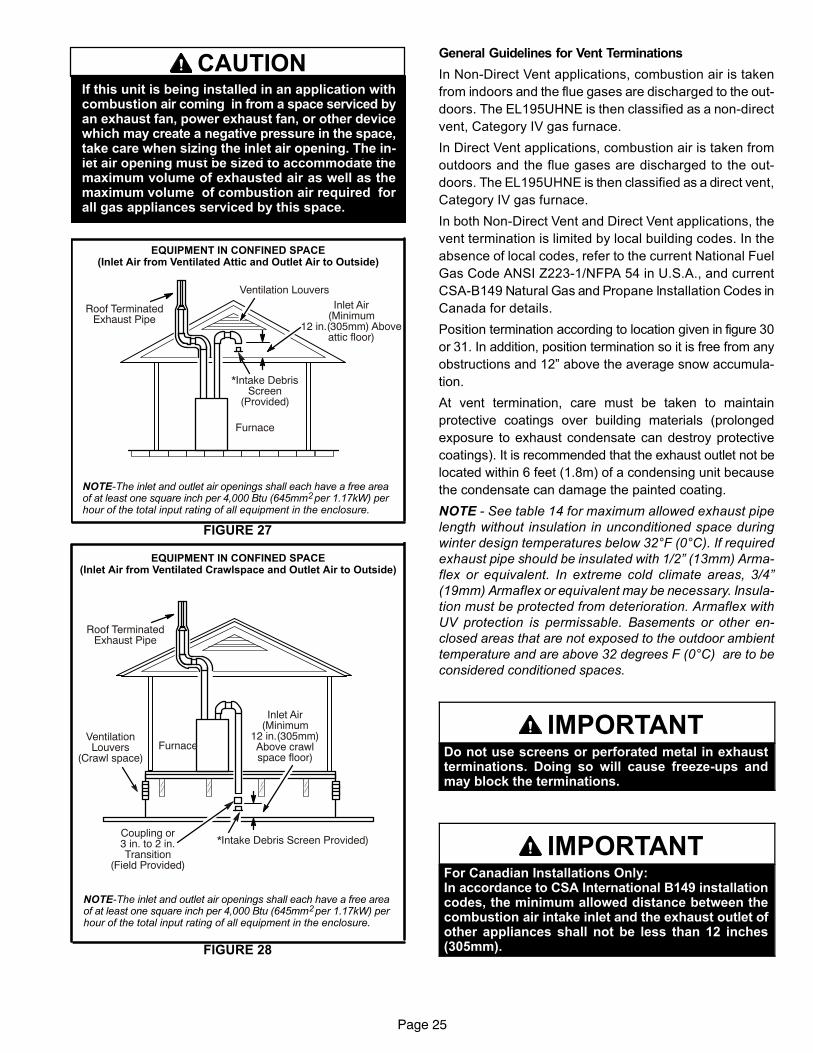
CAUTIONIf this unit is being installed in an application withcombustion air coming in from a space serviced byan exhaust fan, power exhaust fan, or other devicewhich may create a negative pressure in the space,take care when sizing the inlet air opening. The inlet air opening must be sized to accommodate themaximum volume of exhausted air as well as themaximum volume of combustion air required forall gas appliances serviced by this space.
FIGURE 27
EQUIPMENT IN CONFINED SPACE(Inlet Air from Ventilated Attic and Outlet Air to Outside)
NOTE-The inlet and outlet air openings shall each have a free areaof at least one square inch per 4,000 Btu (645mm2 per 1.17kW) perhour of the total input rating of all equipment in the enclosure.
Ventilation LouversInlet Air
(Minimum12 in.(305mm) Above
attic floor)
Roof TerminatedExhaust Pipe
Furnace
*Intake DebrisScreen
(Provided)
FIGURE 28
NOTE-The inlet and outlet air openings shall each have a free areaof at least one square inch per 4,000 Btu (645mm2 per 1.17kW) perhour of the total input rating of all equipment in the enclosure.
EQUIPMENT IN CONFINED SPACE(Inlet Air from Ventilated Crawlspace and Outlet Air to Outside)
Roof TerminatedExhaust Pipe
FurnaceVentilationLouvers
(Crawl space)
*Intake Debris Screen Provided)
Inlet Air(Minimum
12 in.(305mm)Above crawlspace floor)
Coupling or3 in. to 2 in.Transition
(Field Provided)
General Guidelines for Vent Terminations
In Non‐Direct Vent applications, combustion air is taken
from indoors and the flue gases are discharged to the out
doors. The EL195UHNE is then classified as a non‐direct
vent, Category IV gas furnace.
In Direct Vent applications, combustion air is taken from
outdoors and the flue gases are discharged to the out
doors. The EL195UHNE is then classified as a direct vent,
Category IV gas furnace.
In both Non‐Direct Vent and Direct Vent applications, the
vent termination is limited by local building codes. In the
absence of local codes, refer to the current National Fuel
Gas Code ANSI Z223-1/NFPA 54 in U.S.A., and current
CSA-B149 Natural Gas and Propane Installation Codes in
Canada for details.
Position termination according to location given in figure 30
or 31. In addition, position termination so it is free from any
obstructions and 12” above the average snow accumula
tion.
At vent termination, care must be taken to maintain
protective coatings over building materials (prolonged
exposure to exhaust condensate can destroy protective
coatings). It is recommended that the exhaust outlet not be
located within 6 feet (1.8m) of a condensing unit because
the condensate can damage the painted coating.
NOTE - See table 14 for maximum allowed exhaust pipe
length without insulation in unconditioned space during
winter design temperatures below 32°F (0°C). If required
exhaust pipe should be insulated with 1/2” (13mm) Arma
flex or equivalent. In extreme cold climate areas, 3/4”
(19mm) Armaflex or equivalent may be necessary. Insula
tion must be protected from deterioration. Armaflex with
UV protection is permissable. Basements or other en
closed areas that are not exposed to the outdoor ambient
temperature and are above 32 degrees F (0°C) are to be
considered conditioned spaces.
IMPORTANTDo not use screens or perforated metal in exhaustterminations. Doing so will cause freeze-ups andmay block the terminations.
IMPORTANTFor Canadian Installations Only:In accordance to CSA International B149 installationcodes, the minimum allowed distance between thecombustion air intake inlet and the exhaust outlet ofother appliances shall not be less than 12 inches(305mm).

Page 26
TABLE 14Maximum Allowable Exhaust Vent Pipe Length (in ft.) Without Insulation In Unconditioned Space For
Winter Design Temperatures Single - Stage High Efficiency Furnace
Winter DesignTemperatures1
°F (°C)
Vent PipeDiameter
Unit Input Size
040 060 080 100
32 to 21(0 to -6)
PVC 2PP PVC 2PP PVC 2PP PVC 2PP
2 in. 18 16 31 28 50 48 30 30
2-1/2 in. 13 N/A 24 N/A 42 N/A 56 N/A
3 in. 9 9 18 18 35 35 47 47
20 to 1(-7 to -17)
2 in 9 8 18 16 32 29 30 30
2-1/2 in. 5 N/A 13 N/A 24 N/A 34 N/A
3 in. N/A N/A 8 8 19 19 26 26
0 to -20(-18 to -29)
2 in. 5 N/A 12 10 22 19 30 27
2-1/2 in. N/A N/A 7 N/A 15 N/A 22 N/A
3 in. N/A N/A N/A N/A 10 10 16 16
1Refer to 99% Minimum Design Temperature table provided in the current edition of the ASHRAE Fundamentals Handbook.
2 Poly-Propylene vent pipe (PP) by Duravent and Centrotherm.
NOTE - Concentric terminations are the equivalent of 5' and should be considered when measuring pipe length.
NOTE - Maximum uninsulated vent lengths listed may include the termination(vent pipe exterior to the structure) and cannot exceed 5 linear feet or themaximum allowable intake or exhaust vent length listed in table 12 or 13 which ever is less.
NOTE - If insulation is required in an unconditioned space, it must be located on the pipe closest to the furnace. See figure29.
FIGURE 29
ConditionedSpace Unconditioned
Space
ExhaustPipe
IntakePipe
ConditionedSpace
Pipe Insulation

Page 27
FIGURE 30
VENT TERMINATION CLEARANCESFOR NON-DIRECT VENT INSTALLATIONS IN THE USA AND CANADA
K
D
E
L
B
C
F
G
A
B
JA
M
I
H
INSIDE CORNER
DETAIL
VENT TERMINAL AIR SUPPLY INLETAREA WHERE TERMINALIS NOT PERMITTED
FixedClosedOperable
B
FixedClosed
Operable
B
B
A =
B =
C =
D =
E =
F =
G =
H =
I =
J =
K =
L =
M =
US Installations1 Canadian Installations2
12 inches (305mm) or 12 in. (305mm)above average snow accumulation.
12 inches (305mm) or 12 in. (305mm)above average snow accumulation.
Clearance above grade, veranda,porch, deck or balcony
Clearance to window ordoor that may be opened 4 feet (1.2 m) below or to side of opening;
1 foot (30cm) above opening
6 inches (152mm) for appliances <10,000Btuh (3kw), 12 inches (305mm) for appliances > 10,000 Btuh (3kw) and
<100,000 Btuh (30kw), 36 inches (.9m)for appliances > 100,000 Btuh (30kw)
Clearance to permanentlyclosed window
Vertical clearance to ventilated soffit located above the terminal within a
horizontal distance of 2 feet (610 mm)from the center line of the terminal
Clearance to unventilated soffit
Clearance to outside corner
Clearance to inside corner
Clearance to each side of center line extended above meter / regulator assembly
Clearance to service regulatorvent outlet
Clearance to non-mechanical airsupply inlet to building or the com
bustion air inlet to any other appliance
Clearance to mechanical air supply inlet
Clearance above paved sidewalk orpaved driveway located on public property
Clearance under veranda, porch, deck or balcony
* 12”
* Equal to or greater than soffit depth.
*
* 3 feet (.9m)
* 12”
3 feet (.9m) within a height 15 feet (4.5m)above the meter / regulator assembly
3 feet (.9m)
6 inches (152mm) for appliances <10,000Btuh (3kw), 12 inches (305mm) for appliances > 10,000 Btuh (3kw) and
<100,000 Btuh (30kw), 36 inches (.9m)for appliances > 100,000 Btuh (30kw)
3 feet (.9m) above if within 10 feet(3m) horizontally
6 feet (1.8m)
7 feet (2.1m)†
12 inches (305mm)‡
1 In accordance with the current ANSI Z223.1/NFPA 54 Natural Fuel Gas Code2 In accordance with the current CSA B149.1, Natural Gas and Propane Installation Code † A vent shall not terminate directly above a sidewalk or paved driveway that islocated between two single family dwellings and serves both dwellings.
‡ Permitted only if veranda, porch, deck or balcony is fully openon a minimum of two sides beneath the floor. Lennox recommendsavoiding this location if possible.
4 feet (1.2 m) below or to side of opening;1 foot (30 cm) above opening
7 feet (2.1m)†
* Equal to or greater than soffit depth.
* Equal to or greater than soffit depth. * Equal to or greater than soffit depth.
* No minimum to outside corner * No minimum to outside corner
3 feet (.9m) within a height 15 feet (4.5m)above the meter / regulator assembly
*12 inches (305mm)‡
* *
*For clearances not specified in ANSI Z223.1/NFPA 54 or CSAB149.1, clearance will be in accordance with local installationcodes and the requirements of the gas supplier and these installation instructions.”

Page 28
FIGURE 31
VENT TERMINATION CLEARANCESFOR DIRECT VENT INSTALLATIONS IN THE USA AND CANADA
K
D
E
L
B
C
F
G
A
B
JA
M
I
H
INSIDE CORNER
DETAIL
VENT TERMINAL AIR SUPPLY INLETAREA WHERE TERMINALIS NOT PERMITTED
FixedClosedOperable
B
FixedClosed
Operable
B
B
A =
B =
C =
D =
E =
F =
G =
H =
I =
J =
K =
L =
M =
US Installations1 Canadian Installations2
12 inches (305mm) or 12 in. (305mm)above average snow accumulation.
12 inches (305mm) or 12 in. (305mm)above average snow accumulation.
Clearance above grade, veranda,porch, deck or balcony
Clearance to window ordoor that may be opened
6 inches (152mm) for appliances <10,000Btuh (3kw), 9 inches (228mm) for ap
pliances > 10,000 Btuh (3kw) and <50,000Btuh (15 kw), 12 inches (305mm) for ap
pliances > 50,000 Btuh (15kw)
6 inches (152mm) for appliances <10,000Btuh (3kw), 12 inches (305mm) for appliances > 10,000 Btuh (3kw) and
<100,000 Btuh (30kw), 36 inches (.9m)for appliances > 100,000 Btuh (30kw)
Clearance to permanentlyclosed window
Vertical clearance to ventilated soffit located above the terminal within a
horizontal distance of 2 feet (610mm)from the center line of the terminal
Clearance to unventilated soffit
Clearance to outside corner
Clearance to inside corner
Clearance to each side of center line extended above meter / regulator assembly
Clearance to service regulatorvent outlet
Clearance to non-mechanical airsupply inlet to building or the com
bustion air inlet to any other appliance
Clearance to mechanical air supply inlet
Clearance above paved sidewalk orpaved driveway located on public property
Clearance under veranda, porch, deck or balcony
* 12”
*
*
* 7 feet (2.1m)
3 feet (.9m) within a height 15 feet (4.5m)above the meter / regulator assembly
3 feet (.9m)
6 inches (152mm) for appliances <10,000Btuh (3kw), 9 inches (228mm) for ap
pliances > 10,000 Btuh (3kw) and <50,000Btuh (15 kw), 12 inches (305mm) for ap
pliances > 50,000 Btuh (15kw)
6 inches (152mm) for appliances <10,000Btuh (3kw), 12 inches (305mm) for appliances > 10,000 Btuh (3kw) and
<100,000 Btuh (30kw), 36 inches (.9m)for appliances > 100,000 Btuh (30kw)
3 feet (.9m) above if within 10 feet(3m) horizontally
6 feet (1.8m)
7 feet (2.1m)†
12 inches (305mm)‡
1 In accordance with the current ANSI Z223.1/NFPA 54 Natural Fuel Gas Code2 In accordance with the current CSA B149.1, Natural Gas and Propane Installation Code *For clearances not specified in ANSI Z223.1/NFPA 54 or CSA
B149.1, clearance will be in accordance with local installationcodes and the requirements of the gas supplier and theseinstallation instructions.”
† A vent shall not terminate directly above a sidewalk or paved driveway that is locatedbetween two single family dwellings and serves both dwellings.
‡ Permitted only if veranda, porch, deck or balcony is fully open on a minimum oftwo sides beneath the floor. Lennox recommends avoiding this location if possible.
* 12”
* Equal to or greater than soffit depth * Equal to or greater than soffit depth* Equal to or greater than soffit depth
* Equal to or greater than soffit depth * Equal to or greater than soffit depth
* No minimum to outside corner * No minimum to outside corner
3 feet (.9m) within a height 15 feet (4.5m)above the meter / regulator assembly
3 feet (.9m)
*
*12 inches (305mm)‡

Page 29
Details of Intake and Exhaust Piping Terminations for
Direct Vent Installations
NOTE - In Direct Vent installations, combustion air is taken from outdoors and flue gases are discharged to outdoors.
NOTE - Flue gas may be slightly acidic and may adverselyaffect some building materials. If any vent termination isused and the flue gasses may impinge on the building material, a corrosion-resistant shield (minimum 24 inchessquare) should be used to protect the wall surface. If theoptional tee is used, the protective shield is recommended.The shield should be constructed using wood, plastic,sheet metal or other suitable material. All seams, joints,cracks, etc. in the affected area should be sealed using anappropriate sealant. See figure 40.
Intake and exhaust pipes may be routed either horizontallythrough an outside wall or vertically through the roof. In attic or closet installations, vertical termination through theroof is preferred. Figures 32 through 42 show typicalterminations.
1. Intake and exhaust terminations are not required to bein the same pressure zone. You may exit the intake onone side of the structure and the exhaust on anotherside (figure 33). You may exit the exhaust out the roofand the intake out the side of the structure (figure 34).
2. Intake and exhaust pipes should be placed as closetogether as possible at termination end (refer to illustrations). Maximum separation is 3” (76mm) on roofterminations and 6” (152mm) on side wall terminations.
NOTE - When venting in different pressure zones, the
maximum separation requirement of intake and ex
haust pipe DOES NOT apply.
3. On roof terminations, the intake piping should terminate straight down using two 90° elbows (See figure32).
4. Exhaust piping must terminate straight out or up asshown. A reducer may be required on the exhaust piping at the point where it exits the structure to improvethe velocity of exhaust away from the intake piping.See table 15.
FIGURE 32
UNCONDITIONEDATTIC SPACE
1/2” (13mm) FOAMINSULATION IN
UNCONDITIONEDSPACE
3”(76mm) MAX.
12” (305mm) ABOVEAVERAGE SNOWACCUMULATION
3” (76mm) OR2” (51mm) PVC
PROVIDE SUPPORTFOR INTAKE ANDEXHAUST LINES
8” (203mm) MIN
Inches(mm)
DIRECT VENT ROOF TERMINATION KIT(15F75 or 44J41)
FIGURE 33
ExhaustPipe
Furnace
Exiting Exhaust and Intake Vent(different pressure zones)
Inlet Air(Minimum 12 in.305 MM) abovegrade or snowaccumulation
FIGURE 34
Roof TerminatedExhaust Pipe
Furnace
Exiting Exhaust and Intake Vent(different pressure zones)
Inlet Air(Minimum 12 in.305 MM) abovegrade or snowaccumulation
TABLE 15EXHAUST PIPE TERMINATION SIZE REDUCTION
EL195UHNEMODEL Exhaust Pipe Size
TerminationPipe Size
*040 and 060 2” (51mm), 2-1/2”(64mm), 3” (76mm)
1-1/2” (38mm)
*080 2” (51mm)100 2” (51mm)
*-040, -060 and -080 units with the flush mount terminationmust use the 1-1/2”accelerator supplied with the kit.
NOTE - Care must be taken to avoid recirculation of ex
haust back into intake pipe.
5. On field-supplied terminations for side wall exit, ex
haust piping may extend a maximum of 12 inches
(305mm) for 2” PVC and 20 inches (508mm) for 3”
(76mm) PVC beyond the outside wall. Intake piping
should be as short as possible. See figure 40.
6. On field-supplied terminations, a minimum distance
between the end of the exhaust pipe and the end of
the intake pipe without a termination elbow is 8” and a
minimum distance of 6” with a termination elbow. See
figure 40.

Page 30
7. If intake and exhaust piping must be run up a side wall
to position above snow accumulation or other ob
structions, piping must be supported. At least one
bracket must be used within 6” from the top of the el
bow and then every 24” (610mm) as shown in figure
40, to prevent any movement in any direction. When
exhaust and intake piping must be run up an outside
wall, the exhaust piping must be terminated with pipe
sized per table 15.The intake piping may be equipped
with a 90° elbow turndown. Using turndown will add 5
feet (1.5m) to the equivalent length of the pipe
8. A multiple furnace installation may use a group of up to
four terminations assembled together horizontally, as
shown in figure 38.
FIGURE 35
2” EXTENSION FOR 2” PVCPIPE1” EXTENSION FOR 3”PVC PIPE
1-1/2” ACCELERATOR
FURNACEEXHAUST
PIPE
FURNACEINTAKE
PIPE
4''
GLUE EXHAUSTEND FLUSH INTO
TERMINATION
FLATSIDE
FLUSH-MOUNT SIDE WALL TERMINATION51W11 (US) or 51W12 (Canada)
FIGURE 36
DIRECT VENT CONCENTRIC ROOFTOP TERMINATION71M80, 69M29 or 60L46 (US)44W92 or 44W93 (Canada)
MinimumAbove Average
SnowAccumulation
SHEET METAL STRAP(Clamp and sheet metal strap
must be field installed to supportthe weight of the termination kit.)
FLASHING(Not Furnished)
CLAMPFIELD-PROVIDED
REDUCER MAY BE REQUIREDTO ADAPT LARGER VENT
PIPE SIZE TO TERMINATION
12” (305mm) INTAKEAIR
EXHAUSTVENT
12” (305mm) Min.above grade oraverage snowaccumulation.
FIGURE 37
DIRECT VENT CONCENTRIC WALL TERMINATION71M80, 69M29 or 60L46 (US)44W92 or 44W93 (Canada)
INTAKEAIR
INTAKEAIRINTAKE
AIR
OUTSIDEWALL
GRADE
CLAMP(Not Furnished)
FIELD-PROVIDEDREDUCER MAY BE REQUIRED
TO ADAPT LARGER VENTPIPE SIZE TO TERMINATION
EXHAUSTVENT
EXHAUSTVENT
FIGURE 38
EXHAUSTVENT
INTAKEAIR
5-1/2”(140mm)
Front View
12”(305mm)
5”(127mm)
18” MAX.(457mm)
EXHAUST VENT
INTAKEAIR
OPTIONAL VENT TERMINATION FOR MULTIPLE UNITINSTALLATION OF DIRECT VENT WALL TERMINATION KIT
(30G28 or 81J20)
Inches (mm)
Side View
12” (305mm) Min.above grade oraverage snow accumulation.
optional intake elbow
DIRECT VENT APPLICATIONUSING EXISTING CHIMNEY
NOTE - Do not discharge exhaust gases directly into any chimney or vent stack. If vertical discharge through an existing unused chimney or stack is required, insert pipinginside chimney until the pipe open end is above top of chimney and terminate as illustrated. In any exterior portion of chimney, the exhaust vent must be insulated.
FIGURE 39
3” - 8”(76mm-203mm)
STRAIGHT-CUT ORANGLE-CUT IN DIRECTION
OF ROOF SLOPE *
EXHAUST VENT1/2” (13mm)
WEATHERPROOFINSULATION
SHOULDER OF FITTINGSPROVIDE SUPPORT
OF PIPE ON TOP PLATE
ALTERNATEINTAKE PIPE
INTAKE PIPEINSULATION (optional)
EXTERIORPORTION OF
CHIMNEY
INSULATETO FORM
SEAL
SHEETMETAL TOP
PLATE
Minimum 12” (305MM)above chimney top
plate or average snowaccumulation
8” - 12”(203mm - 305mm)
3”-8”(76mm-203mm)

Page 31
FIGURE 40
* Use wall support every 24” (610 mm). Use two wall supports if extension is greater than 24” (610 mm) but less than 48” (1219 mm).NOTE − One wall support must be within 6” (152 mm)from top of each pipe (intake and exhaust) to preventmovement in any direction.
NOTE − FIELD−PROVIDEDREDUCER MAY BE
REQUIRED TO ADAPTLARGER VENT PIPE SIZE
TO TERMINATION
STRAIGHTAPPPLICATION
EXTENDEDAPPLICATION
D
B
D
B
A
2” (51mm)Vent Pipe
3” (76mm)Vent Pipe
A− Minimum clearanceabove grade or average
snow accumulation
B− Maximum horizontal separation between intake and exhaust
D− Maximum exhaustpipe length
E− Maximum wall supportdistance from top of each
pipe (intake/exhaust)
12” (305 mm)
12” (305 mm)
12” (305 mm)
6” (152 mm)6” (152 mm)
6” (152 mm)6” (152 mm)
8” (203 mm)8” (203 mm)
20” (508 mm)
6” (152 mm)6” (152 mm)
Front View ofIntake and Exhaust
Intake Exhaust
A
C
B
1
2
D
A
C 3IntakeElbow
ExhaustB
A
D
2” (51MM)Vent Pipe
3” (76MM)Vent Pipe
A− Clearance abovegrade or average snow
accumulation
B− Horizontalseparation betweenintake and exhaust
C− Minimum fromend of exhaust to
inlet of intake
D− Exhaust pipe length
E− Wall support distancefrom top of each pipe
(intake/exhaust)
12” (305 mm) Min. 12” (305 mm) Min.
6” (152 mm) Min.24” (610 mm) Max.
9” (227 mm) Min.
12” (305 mm) Min.16” (405 mm) Max.
6” (152 mm) Max.
6” (152 mm) Min.24” (610 mm) Max.
9” (227 mm) Min.
12” (305 mm) Min.20” (508 mm) Max.
6” (152 mm) Max.
IntakeElbow
* WALLSUPPORT
B
A
DE
B
DE
A
ALTERNATE TERMINATIONS (TEE & FORTY−FIVE DEGREE ELBOWS ONLY)
D
C
12”
1
2
E
B
A
1 The exhaust termination tee should be connected to the 2” or 3” PVC flue pipe as shown in the illustration.Do not use an accelerator in applications that include an exhaust termination tee.The accelerator is not required.
2 As required. Flue gas may be acidic and may adversely affect some building materials. If a side wall venttermination is used and flue gases will impinge on the building materials, a corrosion−resistant shield(24 inches square) should be used to protect the wall surface. If optional tee is used, the protective shieldis recommended. The shield should be constructed using wood, sheet metal or other suitable material.All seams, joints, cracks, etc. in affected area, should be sealed using an appropriate sealant.
3 Exhaust pipe 45° elbow can be rotated to the side away from the combustion air inlet to direct exhaust away from adjacent property. The exhaust must never be directed toward the combustion air inlet.
C2 -Minimum from end ofexhaust to inlet of intake
C1 -Minimum from end ofexhaust to inlet of intake
FIELD FABRICATED WALL TERMINATION
C1 C2
C1C2
See venting table 12 for maximum venting lengthswith this arrangement.
Page 32
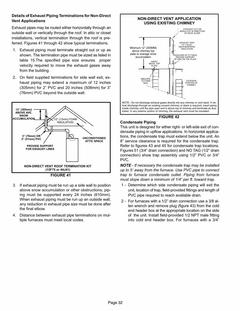
Details of Exhaust Piping Terminations for Non‐Direct
Vent Applications
Exhaust pipes may be routed either horizontally through an
outside wall or vertically through the roof. In attic or closet
installations, vertical termination through the roof is pre
ferred. Figures 41 through 42 show typical terminations.
1. Exhaust piping must terminate straight out or up as
shown. The termination pipe must be sized as listed in
table 15.The specified pipe size ensures proper
velocity required to move the exhaust gases away
from the building.
2. On field supplied terminations for side wall exit, ex
haust piping may extend a maximum of 12 inches
(305mm) for 2” PVC and 20 inches (508mm) for 3”
(76mm) PVC beyond the outside wall.
FIGURE 41
NON-DIRECT VENT ROOF TERMINATION KIT(15F75 or 44J41)
UNCONDITIONEDATTIC SPACE
3” (76mm) OR2” (51mm) PVC
PROVIDE SUPPORTFOR EXHAUST LINES
12” (305mm)ABOVE AVE.
SNOWACCUMULATION 1/2” (13mm) FOAM
INSULATION
3. If exhaust piping must be run up a side wall to position
above snow accumulation or other obstructions, pip
ing must be supported every 24 inches (610mm).
When exhaust piping must be run up an outside wall,
any reduction in exhaust pipe size must be done after
the final elbow.
4. Distance between exhaust pipe terminations on mul
tiple furnaces must meet local codes.
NOTE - Do not discharge exhaust gases directly into any chimney or vent stack. If vertical discharge through an existing unused chimney or stack is required, insert pipinginside chimney until the pipe open end is above top of chimney and terminate as illustrated. In any exterior portion of chimney, the exhaust vent must be insulated.
FIGURE 42
STRAIGHT-CUT ORANGLE-CUT IN DIRECTION
OF ROOF SLOPE
EXHAUST VENT1/2” (13mm)
WEATHERPROOFINSULATION
SHOULDER OF FITTINGSPROVIDE SUPPORT
OF PIPE ON TOP PLATE
EXTERIORPORTION OF
CHIMNEY
INSULATETO FORM
SEAL
SHEETMETAL TOP
PLATE
NON-DIRECT VENT APPLICATIONUSING EXISTING CHIMNEY
Minimum 12” (305MM)above chimney top
plate or average snowaccumulation
Condensate Piping
This unit is designed for either right‐ or left‐side exit of con
densate piping in upflow applications. In horizontal applica
tions, the condensate trap must extend below the unit. An
8” service clearance is required for the condensate trap.
Refer to figures 43 and 45 for condensate trap locations.
Figures 51 (3/4” drain connection) and NO TAG (1/2” drain
connection) show trap assembly using 1/2” PVC or 3/4”
PVC.
NOTE - If necessary the condensate trap may be installed
up to 5’ away from the furnace. Use PVC pipe to connect
trap to furnace condensate outlet. Piping from furnace
must slope down a minimum of 1/4” per ft. toward trap.
1 - Determine which side condensate piping will exit the
unit, location of trap, field-provided fittings and length of
PVC pipe required to reach available drain.
2 - For furnaces with a 1/2” drain connection use a 3/8 al
len wrench and remove plug (figure 43) from the cold
end header box at the appropriate location on the side
of the unit. Install field-provided 1/2 NPT male fitting
into cold end header box. For furnaces with a 3/4”

Page 33
drain connection use a large flat head screw driver or a
1/2” drive socket extension and remove plug. Install
provided 3/4 NPT street elbow fitting into cold end
header box. Use Teflon tape or appropriate pipe dope.
NOTE - Cold end header box drain plugs are factory in
stalled. Check the unused plug for tightness to prevent
leakage.
3 - Install the cap over the clean out opening at the base
of the trap. Secure with clamp. See figure 51 or
NO TAG.
4 - Install drain trap using appropriate PVC fittings, glue
all joints. Glue the provided drain trap as shown in fig
ure 51 or NO TAG. Route the condensate line to an
open drain. Condensate line must maintain a 1/4”
downward slope from the furnace to the drain.
FIGURE 43
CONDENSATE TRAP AND PLUG LOCATIONS(Unit shown in upflow position)
NOTE - In upflow applications where side return
air filter is installed on same side as the conden
sate trap, filter rack must be installed beyond
condensate trap or trap must be re-located to
avoid interference.
Trap(same onright side)
Plug(same on left side)
1-1/2 in.
5 - Figures 46 and 48 show the furnace and evaporator
coil using a separate drain. If necessary the conden
sate line from the furnace and evaporator coil can
drain together. See figures 47, 49 and 50.
Upflow furnace (figure 49) - In upflow furnace applica
tions the field provided vent must be a minimum 1” to a
maximum 2” length above the condensate drain outlet
connection. Any length above 2” may result in a
flooded heat exchanger if the combined primary drain
line were to become restricted.
Horizontal furnace (figure 50) - In horizontal furnace
applications the field provided vent must be a mini
mum 4” to a maximum 5” length above the condensate
drain outlet connection. Any length above 5” may re
sult in a flooded heat exchanger if the combined pri
mary drain line were to become restricted.
NOTE - In horizontal applications it is recommended to
install a secondary drain pan underneath the unit and
trap assembly.
NOTE - Appropriately sized tubing and barbed fitting may
be used for condensate drain. Attach to the drain on the
trap using a hose clamp. See figure 44.
FIGURE 44
Tubing
Hose Clamp
Barbed Fitting
Field Provided Drain Components
Elbow
CAUTIONDo not use copper tubing or existing copper condensate lines for drain line.
6 - If unit will be started immediately upon completion of
installation, prime trap per procedure outlined in Unit
Start-Up section.
Condensate line must slope downward away from the
trap to drain. If drain level is above condensate trap,
condensate pump must be used. Condensate drain
line should be routed within the conditioned space to
avoid freezing of condensate and blockage of drain
line. If this is not possible, a heat cable kit may be used
on the condensate trap and line. Heating cable kit is
available from Lennox in various lengths; 6 ft. (1.8m) -
kit no. 26K68 and 24 ft. (7.3m) - kit no. 26K69.
FIGURE 45
(Unit shown in upflow position with remote trap)
*5’ max.
To Drain
PVCPipeOnly
FieldProvidedVentMin. 1” AboveCondensate
DrainConnection
1” Min.
Trap Can Be Installed aMaximum 5’ From Furnace
2” Max.
CONDENSATE TRAP LOCATIONS
*Piping from furnace must slope down aminimum 1/4” per ft. toward trap

Page 34
FIGURE 46
Unit With Evaporator Coil UsingA Separate Drain
CondensateDrainConnection
Field Provided Vent(1” min. 2” max. abovecondensate connection)
Evaporator drainline required.Trap optional.
FIGURE 47
Horizontal Furnace 4” Min. to 5” Max.abovecondensatedrain connection)
FurnaceCondensateDrainConnection
From Evaporator Coil
Optional
Condensate Trap With Optional Overflow Switch
FIGURE 48
Unit With Evaporatoir Coil Using a Separate Drain(Unit shown in horizontal left-hand discharge position)
.
5’ max.PVC Pipe Only
4”min5”max
EvaporatorCoil
Drain Pan
CondensateDrainConnection
Field Provided Vent(4” min. to 5” max. abovecondensate connection)
Piping from furnace and evaporator coil must slope down a minimum 1/4” per ft. toward trap

Page 35
FIGURE 49
Unit With Evaporator Coil Using a Common Drain
(1”min. to 2” Max.abovecondensate drain connection)
CondensateDrainConnection
Evaporator drainline required.Trap optional.
IMPORTANTWhen combining the furnace and evaporatorcoil drains together, the A/C condensate drainoutlet must be vented to relieve pressure in order for the furnace pressure switch to operateproperly.
FIGURE 50
Unit With Evaporator Coil Using a Common Drain(Unit shown in horizontal left-hand discharge position)
Condensate DrainConnection
(4”min. to 5” Max.abovecondensate drain connection)
5’ max.PVC Pipe Only
4”min5”max
EvaporatorCoil
Drain Pan
Piping from furnace and evaporator coil must slope down a minimum 1/4” per ft. toward trap

Page 36
FIGURE 51
Drain TrapAssembly
(Furnished)
Vent
Drain TrapClean Out
5 FeetMaximum
Coupling 3/4 inch slip X slip(Not Furnished)
90° Elbow 3/4 inch PVC(Not Furnished)
3/4 inch PVC Pipe(Not Furnished)
1/2 inch PVC Pipe(Not Furnished)
Condensate DrainConnection In Unit
Drain Assembly for 1/2 inch Drain Pipe
90° Elbow 3/4 inch PVC
(Not Furnished)
Coupling 3/4 inch slip X slip(Not Furnished)
ToDrain
ToDrain
90° Elbow 3/4 inch PVC
(Not Furnished)
To
ToDrain
90° Elbow 1/2 inch PVC
(Not Furnished)
1/2 inch PVC Pipe(Not Furnished)
Drain Assembly for 3/4 inch Drain Pipe
Condensate DrainConnection In Unit
Condensate DrainConnection In Unit
Vent
ToDrain
Condensate DrainConnection In Unit
Optional Condensate Drain Connection
OptionalDrainPipingFromTrap
DrainTrap Assembly(Furnished)
DrainTrap Assembly with 1/2 inch PipingDrainTrap Assembly with 3/4 inch Piping
1/2 inch3/4 inch
1 (25 mm) Min.2 (50 mm) Max.Above Top OfCondensate DrainConnection In Unit
1 (25 mm) Min. 2 (50 mm) Max. Above TopOf Condensate Drain Connection In Unit
1 (25 mm) Min. 2 (50 mm) Max. Above TopOf Condensate Drain Connection In Unit
Trap
Vent
ToDrain
7(178)
TRAP / DRAIN ASSEMBLY USING 1/2” PVC OR 3/4” PVCCOLD END HEADER BOX WITH 3/4 DRAIN CONNECTION
Adapter 3/4 inch slip X3/4 inch mpt (not furnished)
90° Street Elbow3/4 inch PVC(not furnished)
90° Street Elbow3/4 inch PVC( furnished)
Adapter 3/4 inch slip X3/4 inch mpt (not furnished)

Page 37
III-START‐UP
A-Preliminary and Seasonal Checks
1 - Inspect electrical wiring, both field and factory installedfor loose connections. Tighten as required.
2 - Check voltage at disconnect switch. Voltage must be within range listed on the nameplate. If not, consult the powercompany and have voltage condition corrected before starting unit.
3 - Inspect condition of condensate traps and drain assembly. Disassemble and clean seasonally.
B-Heating Start‐Up
BEFORE LIGHTING the unit, smell all around the fur
nace area for gas. Be sure to smell next to the floor be
cause some gas is heavier than air and will settle on the
floor.
The gas valve on the EL195UHNE is equipped with a gas
control switch. Use only your hand to move the switch.
Never use tools. If the the switch will not move by hand,
replace the valve. Do not try to repair it. Force or at
tempted repair may result in a fire or explosion.
Placing the furnace into operation:
EL195UHNE units are equipped with a SureLight ignition
system. Do not attempt to manually light burners on this
furnace. Each time the thermostat calls for heat, the
burners will automatically light. The ignitor does not get
hot when there is no call for heat on units with SureLight�
ignition system.
Priming Condensate Trap
The condensate trap should be primed with water prior to
start-up to ensure proper condensate drainage. Either
pour 10 fl. oz. (300 ml) of water into the trap, or follow
these steps to prime the trap:
1 - Follow the lighting instructions to place the unit into op
eration.
2 - Set the thermostat to initiate a heating demand.
3 - Allow the burners to fire for approximately 3 minutes.
4 - Adjust the thermostat to deactivate the heating de
mand.
5 - Wait for the combustion air inducer to stop. Set the
thermostat to initiate a heating demand and again al
low the burners to fire for approximately 3 minutes.
6 - Adjust the thermostat to deactivate the heating de
mand and again wait for the combustion air inducer to
stop. At this point, the trap should be primed with suffi
cient water to ensure proper condensate drain opera
tion.
WARNINGIf you do not follow these instructions exactly, a fireor explosion may result causing property damage,personal injury or death.
Gas Valve Operation (Figure 52)
1 - STOP! Read the safety information at the beginning of
this section.
2 - Set the thermostat to the lowest setting.
3 - Turn off all electrical power to the unit.
4 - This furnace is equipped with an ignition device which
automatically lights the burners. Do not try to light the
burners by hand.
5 - Remove the access panel.
6 - Move gas valve switch to OFF. See figure 52.
7 - Wait five minutes to clear out any gas. If you then smell
gas, STOP! Immediately call your gas supplier from a
neighbor's phone. Follow the gas supplier's instruc
tions. If you do not smell gas go to next step.
8 - Move gas valve switch to ON. See figure 52.
FIGURE 52
NEGATIVE AIRPRESSURE PORT
POSITIVE AIRPRESSURE PORT
MANIFOLDPRESSURE TAP
INLETOUTLET
SUPPLYPRESSURE
TAPGAS VALVE SHOWN IN THE ON POSITION
GAS VALVE
9 - Replace the access panel.
10- Turn on all electrical power to to the unit.
11- Set the thermostat to desired setting.
NOTE - When unit is initially started, steps 1 through 11
may need to be repeated to purge air from gas line.
12- If the appliance will not operate, follow the instructions
“Turning Off Gas to Unit” and call your service techni
cian or gas supplier.
Turning Off Gas to Unit
1 - Set the thermostat to the lowest setting.
2 - Turn off all electrical power to the unit if service is to be
performed.
3 - Remove the access panel.
4 - Move gas valve switch to OFF.
5 - Replace the access panel.
Failure To Operate
If the unit fails to operate, check the following:
1 - Is the thermostat calling for heat?
2 - Are access panels securely in place?
3 - Is the main disconnect switch closed?
4 - Is there a blown fuse or tripped breaker?
5 - Is the filter dirty or plugged? Dirty or plugged filters willcause the limit control to shut the unit off.
6 - Is gas turned on at the meter?
7 - Is the manual main shut‐off valve open?
8 - Is the internal manual shut‐off valve open?
9 - Is the unit ignition system in lockout? If the unit locks outagain, inspect the unit for blockages.

Page 38
IV-HEATING SYSTEM SERVICE CHECKS
A-C.S.A. Certification
All units are C.S.A. design certified without modifications.
Refer to the EL195UHNE Operation and Installation In
struction Manual Information.
B-Gas Piping
CAUTIONIf a flexible gas connector is required or allowed bythe authority that has jurisdiction, black iron pipeshall be installed at the gas valve and extend outsidethe furnace cabinet. The flexible connector can thenbe added between the black iron pipe and the gassupply line.
WARNINGDo not over torque (800 in-lbs) or under torque (350in-lbs) when attaching the gas piping to the gasvalve.
Gas supply piping should not allow more than 0.5” W.C.
drop in pressure between gas meter and unit. Supply gas
pipe must not be smaller than unit gas connection.
Compounds used on gas piping threaded joints should be
resistant to action of liquefied petroleum gases.
C-Testing Gas Piping
IMPORTANTIn case emergency shutdown is required, turn offthe main shut‐off valve and disconnect the mainpower to unit. These controls should be properlylabeled by the installer.
When pressure testing gas lines, the gas valve must be dis
connected and isolated. Gas valves can be damaged if
subjected to more than 0.5 psig (14” W.C.). See figure 53.
FIGURE 53
Isolate Gas Valve
Manual Main Shut-Off Valve WillNot Hold Normal Test Pressure
1/8” N.P.T. Plugged Tap
Cap
When checking piping connections for gas leaks, use pre
ferred means. Kitchen detergents can cause harmful corro
sion on various metals used in gas piping. Use of a specialty
Gas Leak Detector is strongly recommended. It is available
through Lennox under part number 31B2001. See Corp.
8411-L10, for further details.
WARNING
Do not use matches, candles, flame or any othersource of ignition to check for gas leaks.
D-Gas Supply, Manifold and Signal Pressure
Gas Flow (Approximate)
TABLE 16
GAS METER CLOCKING CHART
EL195Unit
Seconds for One Revolution
Natural LP/Propane
1 cu ftDial
2 cu ftDial
1 cu ftDial
2 cu ftDia
-040 90 1780 N/A N/A
-060 60 120 150 300
-080 45 90 112 224
-100 36 72 N/A N/A
Natural-1000 btu/cu ft LP/Propane-2500 btu/cu
Furnace should operate at least 5 minutes before check
ing gas flow. Determine time in seconds for two revolu
tions of gas through the meter. (Two revolutions assures a
more accurate time.) Divide by two and compare to time
in table 16. If manifold pressure matches table 18 and rate
is incorrect, check gas orifices for proper size and re
striction. Remove temporary gas meter if installed.
NOTE - To obtain accurate reading, shut off all other gas
appliances connected to meter.
Supply Pressure Measurement
A threaded plug on the inlet side of the gas valve provides
access to the supply pressure tap. Remove the threaded
plug, install a field-provided barbed fitting and connect a
manometer to measure supply pressure. Replace the
threaded plug after measurements have been taken. See
table 17 for supply line pressure.
On multiple unit installations, each unit should be checked
separately, with and without units operating.
TABLE 17Supply Line
Unit Fuel Supply LineWC”
Propane Kit0-4500 ft
(0-1372m)All Nat 4.5 - 10.5
-040
LP/Propane
N/A N/A
-060 11.0 - 13.0 19K05
-080 11.0 - 13.0 19K06
-110 N/A N/A
NOTE - A natural to L.P. propane gas changeover kit is necessary to con
vert this unit. Refer to the changeover kit installation instruction for the
conversion procedure and manifold pressure measure procedure.

Page 39
Manifold and Signal Pressure Measurement
To correctly measure manifold and signal pressure, follow
the steps below:
1 - Turn off the electrical power and gas supply to the fur
nace.
2 - Remove the threaded plug from the outlet side of the
gas valve and install a field-provided barbed fitting.
Connect measuring device positive “+” to barbed fit
ting to measure manifold pressure. See figure 52 for
manifold location.
3 - Install hoses and meter as shown in figure 56 for signal
pressure measurement.
4 - After allowing unit to stabilize for 8 minutes, record
manifold pressure and compare to value in table 18. If
manifold pressure is within range, rate check is com
plete move to step 6. If manifold pressure is not within
range continue.
Valve is not adjustable. Do not adjust manifold
pressure.
5 - Record signal pressure and compare to value in table
18. If signal pressure is within range continue. If the
signal is not within range go to “Troubleshooting”.
6 - Shut off unit and remove manometer and signal meter
after accurate readings has been obtained.
7 - Restart unit and check for gas leaks. Seal any leaksfound.
If the unit has difficulty igniting or ignites with loud res
onance the air orifice must be checked and replaced if
necessary.
TABLE 18
Manifold and Signal Pressure (inches w.c.)
Model Manifold Nat Manifold LP Signal
040
3.2 - 3.8
N/a 0.80 - 0.93
0603.6
0.69 - 0.93
080 0.73 - 0.93
100 N/a 0.75 - 0.93
Air Orifice Replacement
Do not replace the air orifice until the problem has been de
termined. If the unit has difficulty igniting the orifice is over
sized and brings in too much air. If the unit ignites but with
loud resonance the orifice is too small and needs more air.
The air orifice is located inside the gray coupling between
the clamps. Figure 55 show corresponding steps with the
steps below.
1 - Turn off the electrical power and gas supply to the fur
nace.
2 - Remove the black air pressure tube on the air intake
coupling.
3 - Use a 5/16” nut driver to loosen the clamps on the gray
coupling.
4 - Remove the two screws attaching the air intake cou
pling to the furnace cabinet.
5 - Remove the air intake coupling. If the air intake cou
pling is still too difficult to remove, then remove the two
screws from the right side of the top cap and one from
the far right side of the blower deck that attaches to the
cabinet. See figure 54. Carefully pull cabinet side away
from air intake coupling, then remove the air intake
coupling. Note: Be careful not to bend the cabinet
side.
6 - Remove the air orifice. Check the “Part” number
stamped on the air orifice. See table 19. If the part num
ber is incorrect, then replace it with the proper air ori
fice. Repeat manifold check. If air orifice is correct di
ameter, then it must be replaced to resolve ignition or
resonance issue. See table 19 for replacement.
7 - Reinstall the air orifice on the left side of the coupling
and push firmly into place.
8 - Reinstall air intake coupling making sure it is fully seat
ed in the gray coupling. Re-install the two screws at
taching the air intake coupling to the furnace cabinet.
Tighten clamps to secure the coupling. Re-install the
two screws on the right side of the top cap and the one
screw that attaches the blower deck to the cabinet.
9 - Reconnect the black air pressure tube.
10 -Repeat manifold and signal pressure check. If unit ig
nites and manifold and signal pressure are correct,
move on to combustion check. If unit still does not ig
nite or ignites with loud resonance go to Troubleshoot
ing figure 57.
FIGURE 54
REMOVE SCREWS
Screws
Screw

Page 40
FIGURE 55
Gray Coupling
2
Air Intake Coupling
3
4
5
67
8
Air Orifice andPart Number
8
9
Air Orifice Replacement
FIGURE 56
Operating Signal Pressure Measurement
TABLE 19
Single-StageProduction Resonance (more air) Difficulty Igniting (less air)
Orifice Size (Part No) Orifice Size Cat No Orifice Size Cat No
040 0.800 (16) 0.812 (01) 21U23 0.787 (20) 21U01
060 0.995 (14) 1.010 (21) 21U02 0.980 (13) 21U25
080 1.105 (12) 1.125 (03) 19X31 1.085 (22) 21U03
100 1.250 (06) 1.281 (19) 19X39 1.219 (04) 19X32

Page 41
Gas manifold pressure withinrange shown in table 18?
Check the following1-Does the unit have the correctair orifice size? See table 19.2 -Is the orifice fully seated tightagainst the elbow ?3 -Is the orifice damaged in anyway?4 - Is the air inlet screen clear ofany obstruction ?
Correct any problems found.Is ignition or resonance issueresolved ?
Check Air OrificeSee Figure 55.
Troubleshooting is complete
Check Gas Manifold Pressure
Replace air orifice.see table 3.
Check signal Pressure
Signal pressure withinrange shown in table 18? Replace gas valve
Check the following1-. Vent /air intake pipe restriction.2- Plugged drain3- Plugged air inlet screen4 - Signal hoses to gas valvefor kinks, loose fit or plugging.
Correct any problems found.Manifold pressure correct ? Replace gas valve
No
Yes
Is ignition or resonanceissue resolved?
Yes Troubleshooting is complete
No
Replace air orifice.see table 19.
No
No
Yes
Troubleshooting Poor Ignition or Combustion Resonance Issues
No
Yes
Yes
FIGURE 57

Page 42
E-Proper CombustionFurnace should operate minimum 15 minutes with correct
manifold pressure and gas flow rate before checking com
bustion. Take combustion sample beyond the flue outlet
and compare to the tables below.
TABLE 20
EL195Model
CO2% For Nat CO2% For LP/Propane
040 6.3 - 7.8 N/A
060 6.5 - 8.2 8.4 - 9.9
080 7.2 - 8.4 9.0 -10.4
100 7.3 - 8.5 N/A
The maximum carbon monoxide reading should not exceed 100ppm.
F-High AltitudeUnits are NOT approved for installations over 4500 ft.
G- Proper Ground and Voltage
WARNINGElectric Shock Hazard. Can causeinjury or death. Unit must be properlygrounded in accordance with nationaland local codes.
A poorly grounded furnace can contribute to premature ignitor failure. Use the following procedure to check forground and voltage to the integrated control.
1 - Measure the AC voltage between Line Neutral (spade
terminals) and “C” terminal (low voltage terminal
block) on the integrated control. See figure 58. A wide
variation in the voltage between Line Neutral and “C”
as a function of load indicates a poor or partial ground.
Compare the readings to the table below. If the read
ings exceed the maximum shown in table 1, make re
pairs before operating the furnace.
2 - In addition, measure the AC voltage from Line Hot to
Line Neutral (spade terminals) on the integrated con
trol. See figure 58. This voltage should be in the range
of 97 to 132 Vac
TABLE 21
Furnace StatusMeasurement VAC
Expected Maximum
Power On Furnace Idle 0.3 2
CAI / Ignitor Energized 0.75 5
Indoor Blower Energized Less than 2 10
CHECK VOLTAGE BETWEEN LINE NEUTRALAND LOW VOLTAGE “C” TERMINAL
Red LED Recall Red LED Recall
CHECK VOLTAGE BETWEEN LINEHOT AND LINE NEUTRAL
FIGURE 58

Page 43
V-TYPICAL OPERATING CHARACTERISTICS
A-Blower Operation and Adjustment1
NOTE- The following is a generalized procedure and
does not apply to all thermostat controls.
1 - Blower operation is dependent on thermostat control
system.
2 - Generally, blower operation is set at thermostat sub
base fan switch. With fan switch in ON position, blower
operates continuously. With fan switch in AUTO position,
blower cycles with demand or runs continuously while
heating or cooling circuit cycles.
3 - Depending on the type of indoor thermostat, blower
and entire unit will be off when the system switch is in
OFF position.
B-Temperature Rise (Figure 59)
Temperature rise for EL195UHNE units depends on unit in
put, blower speed, blower horsepower and static pressure
as marked on the unit rating plate. The blower speed must
be set for unit operation within the range of “TEMP. RISE
°F” listed on the unit rating plate.
FIGURE 59
TEMPERATURE RISE
Supply Duct TemperatureReturn Duct Temperature _
Temperature Rise =
SUPPLYAIR
Temperatures
RETURN AIR
C-External Static Pressure
1 - Tap locations shown in figure 60.
2 - Punch a 1/4” diameter hole in supply and return air ple
nums. Insert manometer hose flush with inside edge of
hole or insulation. Seal around the hose with perma
gum. Connect the zero end of the manometer to the
discharge (supply) side of the system. On ducted sys
tems, connect the other end of manometer to the return
duct as above.
3 - With only the blower motor running and the evaporator
coil dry, observe the manometer reading. Adjust blow
er motor speed to deliver the air desired according to
the job requirements. For heating speed external static
pressure drop must not be more than 0.5” W.C. For
cooling speed external static pressure drop must not
be more than 0.8” W.C.
4 - Seal the hole when the check is complete.
FIGURE 61
EXTERNAL STATIC PRESSURESupply Duct StaticReturn Duct Static +
Total Duct Static = (dry coil)
Duct Static
or
Supply Air
Return Air
High “+”
Low “-”
+ −
D-Blower Speed Taps
Blower speed tap changes are made on the integrated con
trol. See figure 3 or 58. The heating tap is connected to the
“HEAT” terminal and the cooling tap is connected to the
“COOL” terminal. On all units the continuous blower tap is
connected to the “FAN” terminal. Unused taps must be se
cured on two dummy terminals labeled ”PARK. To change
out existing speed tap, turn off power and switch out speed
tap with tap connected to “PARK”. See blower speed tap
table on unit diagram for motor tap colors for each speed.

Page 44
VI-MAINTENANCE
WARNINGELECTRICAL SHOCK, FIRE,OR EXPLOSION HAZARD.
Failure to follow safety warnings exactly could resultin dangerous operation, serious injury, death orproperty damage.Improper servicing could result in dangerous operation, serious injury, death, or property damage.Before servicing, disconnect all electrical power tofurnace.When servicing controls, label all wires prior to disconnecting. Take care to reconnect wires correctly.Verify proper operation after servicing.
WARNINGThe blower access panel must be securely in placewhen the blower and burners are operating. Gasfumes, which could contain carbon monoxide, canbe drawn into living space resulting in personal injury or death.
Annual Furnace Maintenance
At the beginning of each heating season, and to complywith the Lennox Limited Warranty, your system should bechecked as follows:
1- Check wiring for loose connections, voltage at indoor
unit and amperage of indoor motor.
2- Check the condition of the belt and shaft bearings if ap
plicable.
3- Inspect all gas pipe and connections for leaks.
4- Check the cleanliness of filters and change if necessary
(monthly).
5- Check the cleanliness of blower assembly and clean
the housing, blower wheel and blower motor if neces
sary.
6- Inspect the condensate drain and trap for leaks and
cracks. The drain and trap must also be cleaned and the
trap must be primed with water. Inspect the rubber
hoses connected to the pressure switches for cracks or
loose connections, replace as necessary. Remove the
rubber hoses from the cold end header box and inspect
for any blockage, clean as needed. If strainers are in
stalled in the hoses remember to remove and clean be
fore reinstalling the hoses.
7- Evaluate the heat exchanger integrity by inspecting the
heat exchanger per the AHRI heat exchanger inspec
tion procedure. This procedure can be viewed at
www.ahrinet.org
8- Ensure sufficient combustion air is available to the fur
nace. Fresh air grilles and louvers (on the unit and in the
room where the furnace is installed) must be properly
sized, open and unobstructed to provide combustion
air.
9- On condensing furnaces, inspect the furnace intake
and exhaust pipes to make sure they are in place, struc
turally sound, without holes, blockage or leakage and
the exhaust pipe is sloped toward the furnace. Inspect
terminations to ensure they are free of obstructions and
are structurally sound. Inspect the furnace return air
duct connection to ensure the duct is sealed to the fur
nace. Check for air leaks on supply and return ducts and
seal where necessary
10 Inspect the furnace return air duct connection to ensure
the duct is sealed to the furnace. Check for air leaks on
supply and return ducts and seal where necessary.
11 Check the condition of the furnace cabinet insulation
and repair if necessary.
12 Perform a complete combustion analysis during the fur
nace inspection to ensure proper combustion and oper
ation. Consult Service Literature for proper combustion
values.
13 Verify operation of CO detectors and replace batteries
as required.
Perform a general system test. Turn on the furnace tocheck operating functions such as the start-up and shut-offoperation.
1 - Check the operation of the ignition system, inspect
and clean flame sensor. Check microamps before and
after. Check controls and safety devices (gas valve,
flame sensor, temperature limits). Consult Service
Manual for proper operating range. Thermal Limits
should be checked by restricting airflow and not dis
connecting the indoor blower. For additional details,
please see Service and Application Note H049.
2 - Verify that system total static pressure and airflow set
tings are within specific operating parameters.
3 - Clock gas meter to ensure that the unit is operating at
the specified firing rate for each stage of operation.
Check supply, manifold and signal pressures at 35, 70
and 100% capacity as outlined in the unit Service Lit
erature. If manifold pressure adjustment is necessary,
consult the Service Literature for unit specific informa
tion on adjusting gas pressure. Not all gas valves are
adjustable. Verify correct temperature rise.
NOTE - After any heavy snow, ice or frozen fog event the
furnace vent pipes may become restricted. Always check
the vent system and remove any snow or ice that may be
obstructing the plastic intake or exhaust pipes.

Page 45
Winterizing and Condensate Trap Care
1 - Turn off power to the unit.
2 - Have a shallow pan ready to empty condensate water.
3 - Remove the drain plug from the condensate trap and
empty water. Inspect the trap then reinstall the drain
plug and refill trap with water.
Condensate Hose Screens (Figure 62)Check the condensate hose screens for blockage andclean if necessary.
1 - Turn off power to the unit.
2 - Remove hoses from cold end header box. Twist andpull screens to remove.
3 - Inspect screens and rinse with tap water if needed.
4 - Reinstall screens, reconnect hoses and turn on powerto unit.
FIGURE 62
Condensate Hose Screens
Hose Hose
A-Heat Exchanger and Burners
If cleaning the heat exchanger becomes necessary, follow
the below procedures and refer to figure 1 and 63 when dis
assembling unit. Use papers or protective covering in front
of furnace while removing heat exchanger assembly.
1 - Turn off both electrical and gas power supplies to furnace.
2 - Remove exhaust pipe from appliance adaptor butleave adaptor connected to exhaust coupling. Removetop cap and intake air pipe from side of unit.
3 - Label the wires from gas valve, thermal switch, primarylimit switch and make-up box then disconnect them.
4 - Label then disconnect the wires from gas valve, thermal switch, primary limit switch and make-up box.
5 - Disconnect gas supply piping. Remove the screw securing the air fuel plenum and remove along with the airinake assembly as one component.
6 - Remove screws from both sides, top and bottom ofvestibule panel.
7 - Remove heat exchanger. It may be necessary tospread cabinet side to allow more room.
8 - Back wash using steam. Begin from the burner opening on each tube. Steam must not exceed 275°F.
9 - Run a vacuum cleaner over the face of burner. Visuallyinspect inside the burner. Remove any blockage. Replace gasket between burner plate and air fuel plenumthen re-install burner plate.
10 -To clean the combustion air inducer visually inspectand using a wire brush clean where necessary. Usecompressed air to clean off debris and any rust.
11 -Reinstall heat exchanger in vestibule.
12 - Reinstall the air fuel plenum and air intake assembly.
13 - Re-install the combustion air inducer assembly. Make note to re-install all screws. Failure to replace allscrews may cause leaks. Reconnect all wires.
14- Reconnect top cap and exhaust pipe to combustion air inducer outlet. Reconnect intake air pipe.
15 - Reconnect gas supply piping.
16 - Turn on power and gas supply to unit.
17 - Set thermostat and check for proper operation.
18 - Check all piping connections, factory and field, for gasleaks. Use a leak detecting solution or other preferredmeans.
CAUTIONSome soaps used for leak detection are corrosive tocertain metals. Carefully rinse piping thoroughly after leak test has been completed. Do not usematches, candles, flame or other sources of ignitionto check for gas leaks.
19 - If a leak is detected, shut gas and electricity off and repair leak.
20 - Repeat steps 18 and 19 until no leaks are detected..
21 - Replace access panel.

Page 46
BURNER, C.A.I ASSEMBLY &HEAT EXCHANGER REMOVAL
FIGURE 63
Gas Valve
Primary LimitIgnitor
Sensor
Gas Orifice
O Ring
High TemperatureSwitch
(location)
Air Gas Plenum
Gaskets
Burner
Heat Exchanger
Burner Box

Page 47
VII-WIRING DIAGRAM AND SEQUENCE OF OPERATION
1 - Line voltage is applied to L1 and N. the T1 low voltage transformer is energized, and line voltage is applied to B3 indoor blower.
2 - S47 rollout switch(es) must be closed in order for 24V from transformer to be output on integrated control ”R” to power thermostat.
3 - When there is a call for heat, W1 of the thermostat energizes W of the furnace control with 24VAC.
4 - A92 integrated control runs a self-check. S10 primary limit and S21 secondary limit contacts are found to be closed. Call for heat can continue.
5 - A92 integrated control energizes B6 combustion air inducer. S18 combustion air pressure switch closes . Once S18 closes, a 15-second
pre-purge follows.
6 - A92 integrated control energizes R33 ignitor. A 20-second warm-up period begins.
7 - GV1 gas valve opens for a 4-second trial for ignition
8 - Flame is sensed, gas valve remains open for the heat call.
9 - After 30-second delay (from flame sensed), A92 integrated control applies 24VAC to Heat speed of B3 indoor blower.
10 - When heat demand is satisfied, W1 of the indoor thermostat de-energizes W of A92integrated control which de-energizes GV1 gas valve.
B6 combustion air inducer continues a 5-second post-purge period, and B3 indoor blower completes a selected OFF time delay.
1
8
2
46
7
3
9
10
1
55

Page 48
Troubleshooting: Heating Sequence of Operation
HEATING SEQUENCE OF OPERATION
NORMAL HEATING MODE ABNORMAL HEATING MODE
CONTROL SELF-CHECK OKAY?
BURNER OFF?
NORMAL OPERATION:LED SLOW FLASH
NO
YES
YES
GAS VALVE OFF. COMBUSTION AIR INDUCER OFF.INDOOR BLOWER DELAY OFF.
LED SLOW FLASH(RESET CONTROL BY TURNING MAIN POWER OFF.)
LED FLASHES CODE 1 - POLARITYREVERSED.
POWER ON
IS POLARITY CORRECT?
ROLLOUT SWITCH CLOSED?
THERMOSTAT CALLS FOR HEAT:LED SLOW FLASH
IS COMBUSTION AIRPRESSURE SWITCH OPEN?
LED FLASHES CODE 8 - ROLLOUT SWITCH OPEN. GAS VALVE OFF. COMBUSTION AIR INDUCER ON.
INDOOR BLOWER ON.SEQUENCE HOLDS UNTIL ROLLOUT SWITCH CLOSES
AND POWER IS RESET OR T'STAT IS INTERRUPTEDFOR MINIMUM OF 1 SECOND.
LED FLASHES CODE 12 - FLAME SENSEDWITHOUT GAS VALVE ENERGIZED.
GAS VALVE OFF. COMBUSTION AIR INDUCER ON.INDOOR BLOWER ON HEATING SPEED.
LED FLASHES CODE 11 - PRESSURESWITCH CLOSED.
GAS VALVE OFF COMBUSTION AIRINDUCER OFF. INDOOR BLOWER
OFF WITH DELAY.(Sequence holds until pressure switchopens or thermostat resets control.)
NO
NO
YES
YES
IS VOLTAGEABOVE 70 VOLTS?
LED FLASHES CODE 13 - LOW LINE VOLTAGE.CONTROL WILL NOT RESPOND TO A CALL FOR
HEATING UNTIL VOLTAGE RISES ABOVE 75 VOLTS.
NO
NO
NO
IS COMBUSTION AIR INDUCER ENERGIZED?
HAS COMBUSTION AIR PRESSURESWITCH CLOSED IN 2.5 MINUTES?
YES
YESLED FLASHES CODE 9 - PRESSURE SWITCH FAILED
TO CLOSE OR OPENED DURING HEAT DEMAND.PRESSURE SWITCH IS IN WATCHGUARD MODE. GAS
VALVE OFF. COMBUSTION AIR INDUCER OFF.INDOOR BLOWER OFF WITH DELAY. IS 5‐MINUTE
RESET PERIOD COMPLETE?
NO
PRIMARY LIMIT SWITCH. CLOSED?
YES
YES
CONTINUED NEXT PAGE
LED FLASHES CODE 7 - PRIMARYLMIT OPEN. COMBUSTION AIR
INDUCER OFF.I NDOOR BLOWER ONNO
YES
NO
YES
IS THERE A PROPER GROUND?
YES
NOLED FLASHES CODE 2 - IMPROPER
GROUND.
YES
YES

Page 49
Troubleshooting: Heating Sequence of Operation (Continued)
HEATING SEQUENCE CONTINUED
NORMAL HEATING MODE ABNORMAL HEATING MODE
FLAME RECTIFICATION CURRENTCHECK. CAN FLAME BE PROVEN WITHIN4 SECONDS AFTER GAS VALVE OPENS?
(0.5 microamps)
FLAME PRESENT?
INDOOR BLOWER ONAFTER 30-SECOND DELAY
PRIMARY LIMIT SWITCH CLOSED?
COMBUSTION AIR PRESSURESWITCH CLOSED?
LED FLASHES CODE 4 - LOWFLAME SIGNAL.
(Does not affect operation of control)
LED FLASHES CODE 7 - PRIMARY LIMIT OPENGAS VALVE DE-ENERGIZED.
COMBUSTION AIR INDUCER DE-ENERGIZED.INDOOR BLOWER ON UNTIL SWITCH CLOSES.
LIMIT SWITCH CLOSED?
GAS VALVE DE-ENERGIZED.COMBUSTION AIR INDUCER ON.
INDOOR BLOWER OFF WITH DELAYHAS CAI SWITCH CLOSED IN 2.5 MINUTES?
15‐SECOND COMBUSTION AIR INDUCER PREPURGEINITIATED BY CLOSED PRESSURE SWITCH.
YES
IGNITOR WARM‐UP -- 20 SECONDS.
YES
YES
FLAME STABILIZATION PERIOD.
GAS VALVE OFF. COMBUSTION AIR INDUCER ON.INDOOR BLOWER OFF.
HAS CONTROL FAILED TO SENSE FLAME FORFIVE CONSECUTIVE TRIES DURING A SINGLE
HEAT DEMAND?
LED SIGNAL WATCHGUARD FAILURE CODEWATCHGUARD MODE. GAS VALVE OFF.
COMBUSTION AIR INDUCER OFF.INDOOR BLOWER OFF WITH DELAY
IS 60‐MINUTE RESET PERIOD COMPLETE?
YES
4 SECONDS
YES
HAS CONTROL RESET IGNITIONSEQUENCE FOUR TIMES?
FLAME SIGNAL 1.5 MICROAMPS OR GREATER?
YES
YES
YES
ROLLOUT SWITCH CLOSED?LED FLASHES CODE 8 - ROLLOUT SWITCH OPEN.
GAS VALVE POWER OFF. COMBUSTION AIR INDUCER POWERON. INDOOR BLOWER ON SEQUENCE HOLDS UNTIL ROLLOUT
SWITCH IS RESET AND MAIN POWER IS INTERRUPTED ORTHERMOSTAT IS CYCLED OFF/ON FOR 1 SEC. MINIMUM.
YES
THERMOSTAT DEMAND SATISFIED.
LED SLOW FLASH.
COMB. AIR INDUCER CONTINUES 5‐SECONDPOST PURGE AFTER T'STAT DEMAND IS SATISFIED.INDOOR AIR BLOWER COMPLETES SELECTED “OFF”
DELAY BEFORE SHUTTING OFF.
YES
NO
5‐MINUTE PRESSURE SWITCHWATCHGUARD MODE.
YES
IS VOLTAGE ABOVE 70 VOLTS?
LED FLASHES CODE 13 -LOW LINE VOLTAGE.
ONCE VOLTAGE IS ABOVE75 VOLTS, HEATING
SEQUENCE RESTARTS.
NO
YES
YES
YES
NO
NO
NO
NO
NO
NO
YES
YES
NO
NO
NO
YES
YESHAS PRIMARY LIMIT RESET
TIME EXCEEDED 3 MINUTES?
LED FLASHES CODE7 - PRIMARY LIMITOPEN. GAS VALVE,
COMB. AIR INDUCERAND INDOOR BLOWER OFF. LEDs SIGNALLIMIT SWITCH OPEN
UNTIL MAINPOWER IS
INTERRUPTED ORT'STAT IS CYCLED
OFF/ON FOR 1 SEC.MINIMUM. 60-MINUTE
WATCHGUARD PERIOD STARTS AT
TIME LIMIT CLOSES.IS 60-MIN. PERIOD
COMPLETE?NO
YES
4‐SECOND TRIAL FOR IGNITION.GAS VALVE OPENS. IGNITOR ENERGIZED FOR
FIRST 3 SECONDS OF THE TRIAL.
LED FLASHESCODE 10
1 HR PRESSURESWITCH
WATCHGUARDMODE
HAS PRESSURE SWITCH OPENED 5TIMES IN SAME HEAT DEMAND
NO
YES

Page 50
Troubleshooting: Cooling Sequence of Operation
COOLING SEQUENCE OF OPERATION
NORMAL COOLING MODE ABNORMAL COOLING MODE
IGNITION CONTROL MAIN POWER ON.
CONTROL SELF DIAGNOSTIC CHECK.IS CONTROL OPERATING NORMALLY?
YES
LED FLASHES CODE 1 POLARITY REVERSEDCONTROL WILL CONTINUE TO CALL FOR COOLING IN
THIS CONDITION.
POWER ON
LED FLASHES STEADY - CIRCUIT BOARD FAILUREGAS VALVE OFF. COMBUSTION AIR INDUCER OFF.
INDOOR BLOWER OFF WITH NORMAL DELAY.INTERRUPT MAIN POWER TO RESET CONTROL.
YES
IS POLARITY CORRECT?
ROLLOUT SWITCH MONITORED CONTINUOUSLY.IS ROLLOUT SWITCH CLOSED?
LED: SLOW FLASH RATE REMAINS UNCHANGEDTHROUGHOUT COOLING CYCLE.
THERMOSTAT CALLS FOR COOLING.
COMPRESSOR CONTACTOR AND SYSTEM FANENERGIZED WITH 2‐SECOND DELAY
(COOLING SPEED)
COMPRESSOR OFF.
THERMOSTAT OPENS.
SYSTEM FAN AND EAC TERM. OFFWITH 45‐SECOND DELAY.
NO
NO
LED FLASHES CODE 8 ROLLOUT SWITCH OPEN. GASVALVE OFF. COMBUSTION AIR INDUCER ON. INDOOR
BLOWER ON. SEQUENCE HOLDS UNTIL ROLLOUT SWITCHCLOSES AND MAIN POWER IS INTERRUPTED OR
THERMOSTAT IS CYCLED OFF/ON FOR 1 SEC. MINIMUM.
IS VOLTAGEABOVE 70 VOLTS?
LED FLASHES CODE 13 LOW VOLTAGE. CONTROLWILL CONTINUE TO CALL FOR COOLING
IN THIS CONDITION.
YES
YES
NO
NO
IS THERE A PROPER GROUND?
YES
NOLED FLASHES CODE 2 IMPROPER GROUND
CONTROL WILL CONTINUE TO CALL FOR COOLINGIN THIS CONDITION.

Page 51
Troubleshooting: Continuous Fan / Accessories Sequence of Operation
CONTINUOUS FAN / ACCESSORIES SEQUENCE OF OPERATION
LED: SLOW FLASH RATE REMAINSUNCHANGED THROUGHOUT SEQUENCE.
MANUAL FAN SELECTION MADE AT THERMOSTAT.CONTROL (G) ENERGIZES SYSTEM FAN AT FAN
SPEED. EAC TERMINAL IS ENERGIZED.
THERMOSTAT CALLS FOR HEAT (W).
THERMOSTAT CALLS FOR COOLING.
THERMOSTAT OPENS.
SYSTEM FAN SWITCHED TO COOL SPEED.EAC TERM. REMAINS ON.
THERMOSTAT OPENS.
MANUAL FAN SELECTION MADE AT THERMOSTAT.CONTROL (G) ENERGIZES SYSTEM FAN AT FAN
SPEED. EAC TERM. ENERGIZED.
NO YES
YESNO
SYSTEM FAN SWITCHES TO HEAT SPEAD AFTER 30SECOND DELAY. EAC AND HUM TERMINALS REMAIN ON.
SYSTEM FAN CONTINUES FAN SPEED WITHOUTINTERRUPTION. EAC TERMINAL REMAIN ON.
HUM TERMINALS ARE ENERGIZED WITHCOMBUSTION AIR BLOWER.
HUM. TERMINALS OFF AFTER POST PURGEBY COMBUSTION AIR INDUCER. SYTEM FANSWITCHES TO FAN SPEED AFTER BLOWER
OFF DELAY. EAC CONTINUES WITHOUTINTERUPTION.