corner horn plans - decware
TRANSCRIPT

DECWARE CORNER HORN PLANS Designed by Steve Deckert © 1994 ~ 2005
High Fidelity Engineering Co. WWW.DECWARE.COM
READ THIS FIRST ! It is important to understand a few basic points before diving into the construction of these cabinets: This is a fairly complex cabinet design that because of it’s angles require an actual size template to keep the layout true. These instructions are based on this template. This cabinet can be built with a decent table saw, router, drill, belt sander and basic hand tools. We recommend a nail gun that shoots both 1 inch and 2 inch finish nails. This cabinet is held together with a quality grade of carpenter’s wood glue. Finish nails are used to tack everything together while the glue dries. In addition a few 1.5 inch drywall screws in select places are also a good idea. We recommend a high grade 3/4 “ plywood for construction. I have also built these us-ing MDF and high density particle board with reasonable results. The plywood is lighter, more resistant to moisture and several times stronger. MDF or Particle board would shatter like glass should the cabinet fall out of the back of a truck, where plywood would just slide down the road in tact. It is important to decide before you begin how you will finish these cabinets. If you paint them, construction will go much easier because you’ll be able to use wood putty or ideally Bondo for filling imperfections. If you plan to try and stain and varnish the cabi-net, everything will have to be perfect thus doubling the difficulty level of construction. Veneering the cabinets is usually the best alternative if you want them to look like fine furniture. If you do decide to use a veneer keep in mind that many of the pieces will have to be covered before the cabinet is assembled. You will be expected to take your angles and measurements directly off the template as you construct your cabinets. Publishing each part’s dimensions and angles only works when the cabinets are made on a computerized CNC machine. When built by human hands even a 1/2 degree mistake on one angle can multiply itself throughout the angles of the design into a serious problem. Also material thickness varies in this day and age. What you think is 3/4” can often be 1/64th or more shy. The only way to make the box come out correctly with the variables in material and tools is to cut and dry fit each part as you go. This is why an actual size template is provided. Precise cut sheets are not provided with these plans because of the variables involved. You can plan on at least two sheets of 4x8 material for each cabinet. One of the angles in this cabinet requires more then the 45 degrees a table saw can reach to. You will have to construct a jig that will tip the panels being cut an additional 23 degrees so you can rip the panels with a 68 degree edge. On a more encouraging note, this cabinet is divided vertically and the left side is an ex-act mirror image of the right side. Also the cabinet is divided horizontally at it’s center point so the top half of the cabinet is a mirror image of the bottom half. This means you only have to figure out how to build and fit 1/4 of the cabinet because everything after that will just be repeated.
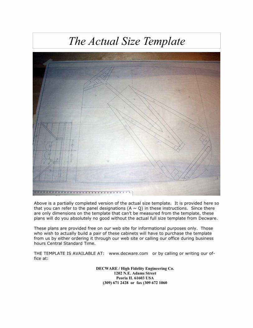
The Actual Size Template
Above is a partially completed version of the actual size template. It is provided here so that you can refer to the panel designations (A ~ Q) in these instructions. Since there are only dimensions on the template that can’t be measured from the template, these plans will do you absolutely no good without the actual full size template from Decware. These plans are provided free on our web site for informational purposes only. Those who wish to actually build a pair of these cabinets will have to purchase the template from us by either ordering it through our web site or calling our office during business hours Central Standard Time. THE TEMPLATE IS AVAILABLE AT: www.decware.com or by calling or writing our of-fice at: DECWARE / High Fidelity Engineering Co.
1202 N.E. Adams Street Peoria IL 61603 USA
(309) 671 2428 or fax (309 672 1060
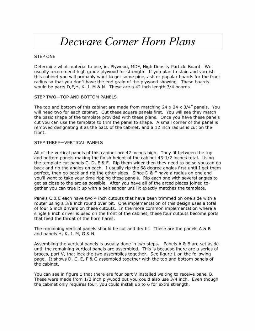
Decware Corner Horn Plans STEP ONE Determine what material to use, ie. Plywood, MDF, High Density Particle Board. We usually recommend high grade plywood for strength. If you plan to stain and varnish this cabinet you will probably want to get some pine, ash or popular boards for the front radius so that you don’t have the end grain of the plywood showing. These boards would be parts D,F,H, K, J, M & N. These are a 42 inch length 3/4 boards. STEP TWO—TOP AND BOTTOM PANELS The top and bottom of this cabinet are made from matching 24 x 24 x 3/4” panels. You will need two for each cabinet. Cut these square panels first. You will see they match the basic shape of the template provided with these plans. Once you have these panels cut you can use the template to trim the panel to shape. A small corner of the panel is removed designating it as the back of the cabinet, and a 12 inch radius is cut on the front. STEP THREE—VERTICAL PANELS All of the vertical panels of this cabinet are 42 inches high. They fit between the top and bottom panels making the finish height of the cabinet 43-1/2 inches total. Using the template cut panels C, D, E & F. Rip them wider then they need to be so you can go back and rip the angles on each. I usually rip the 68 degree angles first until I get them perfect, then go back and rip the other sides. Since D & F have a radius on one end you’ll want to take your time ripping these panels. Rip each one with several angles to get as close to the arc as possible. After you have all of the arced pieces joined to-gether you can true it up with a belt sander until it exactly matches the template. Panels C & E each have two 4 inch cutouts that have been trimmed on one side with a router using a 3/8 inch round over bit. One implementation of this design uses a total of four 5 inch drivers on these cutouts. In the more common implementation where a single 6 inch driver is used on the front of the cabinet, these four cutouts become ports that feed the throat of the horn flares. The remaining vertical panels should be cut and dry fit. These are the panels A & B and panels H, K, J, M, G & N. Assembling the vertical panels is usually done in two steps. Panels A & B are set aside until the remaining vertical panels are assembled. This is because there are a series of braces, part V, that lock the two assemblies together. See figure 1 on the following page. It shows D, C, E, F & G assembled together with the top and bottom panels of the cabinet. You can see in figure 1 that there are four part V installed waiting to receive panel B. These were made from 1/2 inch plywood but you could also use 3/4 inch. Even though the cabinet only requires four, you could install up to 6 for extra strength.
Decware Corner Horn Plans...
FIGURE 1—View from rear
Panel B is tapered on one side to fit into the braces, part V. (Panel B is the vertical divider the splits the horn flares into two halves.) This is done be-cause we want this divider to cut the air like a knife with minimal turbulence. Even though this ta-per is only needed in front of the 4 inch cutouts between the two braces, it’s easier to make the panel with the taper running it’s entire length. Once your satisfied that your as-sembly is fitting together and your happy with the radius on the front (belt sanding) you can fasten the top and bottom pan-els permanently. TIP Before installing panel B you have the opportunity to seal the wood in this area with sanding sealer. Once you install panel B you will no longer be able to reach everything with a paint brush.
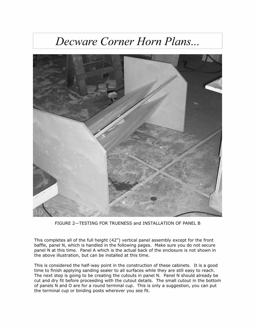
TIP Most if not all of the vertical panel assemblies are heavily glued and shot together with an air finish nailer. When installing the top and bottom panels the same procedure is used with the addition of screws for added strength. It is also okay to add small cleats where the vertical assemblies connect to the top and bottom panels if you want. That way you don’t have to have screw heads showing on the top and bottom of your cabi-net. Also when the top and bottom panels are connected to the vertical assemblies be sure to test the trueness of your work by setting the speaker on it’s side on a perfectly flat floor. See figure 2 on the following page for illustration.
Decware Corner Horn Plans...
FIGURE 2—TESTING FOR TRUENESS and INSTALLATION OF PANEL B
This completes all of the full height (42”) vertical panel assembly except for the front baffle, panel N, which is handled in the following pages. Make sure you do not secure panel N at this time. Panel A which is the actual back of the enclosure is not shown in the above illustration, but can be installed at this time. This is considered the half-way point in the construction of these cabinets. It is a good time to finish applying sanding sealer to all surfaces while they are still easy to reach. The next step is going to be creating the cutouts in panel N. Panel N should already be cut and dry fit before proceeding with the cutout details. The small cutout in the bottom of panels N and O are for a round terminal cup. This is only a suggestion, you can put the terminal cup or binding posts wherever you see fit.

Decware Corner Horn Plans... STEP 4—FRONT PANELS Panel N is the permanent front of the cabinet and provides a backer for the removable front baffle, panel O. Panel O should be cut and dry fit to panel N before any cutouts are made in either panel. When panel N is cut be sure to allow a small amount of clearance at the top and bottom of it so that it can be easily removed. The template shows panels N & O cut for a single 6 inch driver which is the standard configuration. However, the concept behind a removable front baffle is to allow those who want to experiment with different drivers to do so by installing different front baf-fles. This would include a solid front baffle with no cutouts when using the configuration with four 5 inch drivers inside the cabinet. Once you have panel O cut and dry fit to panel N, you can create the cutout for the 6 inch driver. After you have completed panel O with the cutout, you can dry fit it back onto panel N and use a pencil to transfer the opening in panel O to panel N. This way they are certain to line up. The inside of the cutout on panel N should be rounded over with a 1/2 to 3/4 inch round over bit. Once this is done there is one last opening to cut in panel N. Just below your cutout on panel N you will be cutting a square opening large enough to gain access to the four 4 inch holes at the throat of the horn. This way you install and de-install the four 5 inch drivers at any point in the future. Without this opening there is no way to access this area. Refer to the template for locations of these openings. Once you have completed this, you can now permanently install panel N to the cabinet. NOTE: The diameter of your driver cutout should be based on the actual dimensions of the driver you intend to use. NOTE: We recommend the Fostex FE167 full range driver for this cabinet as our ideal choice for lower powered amplifiers. It is a full range driver and used with no crossover. For applications where more power handling is desired you can configure this speaker as a 2-way using an Eminence Alpha-8 midrange driver and a ribbon tweeter like Hi-Vi Re-search’s RT1C-A. When configured as a 2-way with the tweeter, the tweeter should be flush mounted in the front baffle just above the 6 inch driver. It should be wired with a single 4 uf 200 volt poly or mylar capacitor in parallel with the main driver, however the polarity of the tweeter must be reversed. TIP It’s a good idea to line the back of the front baffle with felt and use a generous pattern of screws to hold the front baffle on. I usually run them every 6 inches down each side.

Decware Corner Horn Plans...
FIGURE—3 REAR VIEW OF COMPLETED CABINET
STEP 5—HORN FLARE The actual horn flare was started when you in-stalled the small braces known as part V. From that point the flare ex-pands to the first bend. To create this part we must first make the hori-zontal parts known as parts R & S on the tem-plate. Parts R and S are located exactly 16 inches apart and centered in the verti-cal plane. These are in-stalled next. If you look at the tem-plate it is important to realize that part R, for example, extends all the way to the inside corner of panels A & B. The smaller blocking known as parts P, Q, R, S, T & U are all cut at a length of 16 inches and are set be-tween parts R & S.
For added strength additional blocking can be added to R & S to make them double thick. In the illustration above you can see this was done on the lower set and not done on the upper set. Parts P & Q are actually panels that set the proper angle for the bend in the horn flare. These angles will reflect high frequencies that are too short to make the bend and thus increase the bandwidth of the flare to 4500 Hz when four 5 inch full range drivers are used on the inside of the cabinet instead of the single 6 inch front mounted arrange-ment. NOTE: With a single 6 inch driver in front the horn begins to work at 110 Hz down to 40 Hz. If you use a driver with an fs below 100Hz you can have too much bass.

Decware Corner Horn Plans... Once you have parts R & S installed you will need to create a cardboard template for pieces X & Y. These pieces connect part V to part R & S. Once you get the cardboard template to fit perfectly with no gaps, you can transfer the pattern to wood and cut it out. Remember both of the short edges of pieces X and Y will have angles on them to match up with the 90 degree edges of the connecting parts, R, S & V. We do not pro-vide the angles or template for this part because if anything is just slightly off on the rest of the cabinet and you cut this piece from a template it would not fit tightly. With the addition of this pieces, you have just completed the first section of the horn flare. Make sure that all your joints inside the horn flare are air tight. Use caulk if you have too. FINAL FLARE The final panel that completes the horn flare is often called the “sails” or “wings” of the cabinet. These are trickier then they look to make. The start at the edge of pieces R & S and go down to meet the front edges of the cabinet. There are two ways to build these. One is to cut the panel with straight lines, the other is to cut it so it follows the curve at the front of the cabinet. If you ignore the curve and cut the panels with straight lines, you will have a void between the panel and the curve that will have to be filled with something, either another piece of wood, or Bondo (auto body filler) Myself, I like to cut them to match the curve. This creates a compound radius cut as it curves around so the only way to do it correctly is to once again create a cardboard template first. Once you have a perfect fitting cardboard piece, you can transfer the pattern to wood and cut the panel. Once you have the panel shape cut out, you will need to create the angle at the top edge to meet with parts R & S. On the other wider end of the panel you will also need to create an angle so it meets tightly with the bottom/top panel. This is best done with a practice piece of narrow board and dry fitted until the angles and length are perfect, then repeated with the actual panel. Now that you have the shape cut, and both the top and bottom angles cut, you will have to back-cut behind the radius until it fits tight. By hand is the only way this can be done, and I usually use a coping saw. If the angle of back-cut is not enough you will create a gap when you try to fit the panel. If however it is too much the gap is hidden below the joint and can not be seen. In this case you can back fill the gap with Bondo or Putty. I usually add some cleats under these panels and bracing to make them stronger and easier to connect to the rest of the cabinet. TIP Lay the enclosure on it’s side when fitting these panels so they stay true.
Decware Corner Horn Plans... These panels, W & X, are actually the most difficult ones to get right. Take your time when creating the templates. If your cabinet is going together dead perfect then the pattern you create will fit perfect in all 4 positions in the cabinet. If it does not fit per-fect in all 4 positions then you will have to create a template for each of the 4 positions and you will understand why we don’t try to provide a template for this panel. STEP 6—FINISHING At this stage you cabinet is basically done. You will want to add small braces anywhere you think it would add strength to the cabinet if you haven’t done so. To determine if and where braces should be added you simply knock on the various panels making up the cabinet and listen to the pitch. After your carpentry work is all done, give the whole cabinet a nice sanding and then seal it with sanding sealer and sand it again. If you are veneering the cabinet, you al-ready know what your doing so good luck. STEP 7—INSTALLATION This cabinet must be installed tight into a corner to work. That is because it uses the walls to complete the horn flare. You will run into two issues when you go to install the cabinets into the corners of your room. 1) there will be base boards to deal with and 2) the corner will not be perfectly square. BASEBOARDS For permanent installations you can cut the base board to butt into the cabinet. An-other alternative is to raise the cabinet off the floor to sit just above the baseboards. And finally, if the baseboards are very thin you may be able to ignore them. GASKET Since no corner of any room is perfectly true you will find gaps when you try to butt the cabinet up against the walls. This is handled by installing a 3/4” wide by 5/8” foam weather strip (self adhesive type) to all the edges that contact the walls. This ensures you have an air tight seal against the wall. You must have an air tight seal against the walls. If you are going to paint your cabinets with the same paint that’s on your walls like I of-ten do, I’ll just caulk the cabinet into the corner with a latex painters caulk. That way when it’s time to remove the cabinets I can cut the caulk with a utility knife and repaint the walls. FOR CRAZY AUDIOPHILES Refer to figure 3, you can cap off the hollow cavities and install a plug in parts R & S and fill the hollow cavities with sand. If you never have to move the cabinet this is just icing on the cake.
Decware Corner Horn Plans... ROOM SETUP The ideal situation for these speakers is to place them in the corners on either side of a large opening to an adjoining room. If you place them on a wall with no opening, you will find the soundstage depth will be very limited. This problem can be reduced by installing quadratic theory diffusers on the wall between the loudspeakers from floor level to at least the six foot mark. Another way to approach set up is to create two knee walls that are four feet high and three feet wide. These walls can be used to create a corner somewhere back from the front wall, ideally 6 feet or more. These walls will have to be sand filled because they are not supporting the weight of the house and therefore would be prone to resonate. SUPPORT FORUM Decware will be providing an online support forum for this enclosure design where you can go for advise and to get questions answered. It is also a great place to post pic-tures of your new speakers and brag about how great they sound. AMPLIFICATION No system will ever sound better then it’s weakest link. If you don’t have a great great great amplifier you should be warned that these speakers deserve one. Start with the amp you have and then talk to me about getting one of our Tube amplifiers. The com-bination is a benchmark that becomes impossible to beat by even the most high dollar systems. If you don’t believe that, please schedule a listening appointment with me and come hear it for yourself. CONCLUSION There are technical white papers on the design of the horn that I wrote in 1994 after I built my first pair and realized how good they are. Please consider these white papers part of these plans as both are needed to understand and properly use these speakers. Hope you enjoy these speakers as much as I have. After 11 years they are still my fa-vorite speakers and promise to hold that position for some time to come. Enjoy, Steve Decket DECWARE / High Fidelity Engineering Co.