corky’s vamcorky’s vam--rabrab -...
TRANSCRIPT
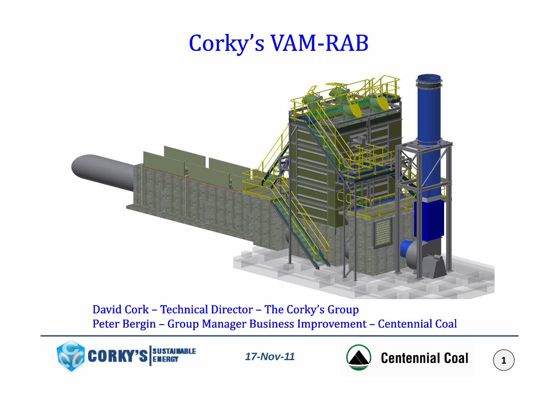
Corky’s VAMCorky’s VAM--RABRAB
David Cork David Cork –– Technical Director Technical Director –– The Corky’s GroupThe Corky’s GroupPeter Bergin Peter Bergin –– Group Manager Business Improvement Group Manager Business Improvement –– Centennial CoalCentennial Coal117-Nov-11
AcknowledgementAcknowledgementAcknowledgement Acknowledgement • Corky’s are the designers, constructors and maintainers of the VAM RAB y g ,
demonstration plant to be developed at Mandalong
• Centennial Coal are the owners of the site on which the demonstration plant• Centennial Coal are the owners of the site on which the demonstration plant will operate.
• The project is jointly funded by NSW Department of Trade & Investment, Regional Infrastructure & Services through the Clean Coal Fund, which is administered by the Minister for Resources & Energy, Centennial Coal and y gy,Corky’s.
A i d h i d il fl h i f NSW• Any views expressed herein do not necessarily reflect the views of NSW DT&IRI&S or the NSW Government.
217-Nov-11
Indentifying the ProblemIndentifying the ProblemIndentifying the ProblemIndentifying the ProblemWorldwide ventilation air methane (VAM) emissions contributesWorldwide, ventilation air methane (VAM) emissions contributesto 17% of manmade greenhouse gas pollution (Mallett & Su, 2004).
These fugitive emissions are heading towards 10% of Australia’semissions by 2020. (Department of Climate Change, 2011)
With a carbon tax proposed to come into effect in July, 2012 inp p yAustralia, it has become a poignant issue to treat and reducethese emissions. The carbon tax in Australia is sufficiently high tol d d l i hi h ld h iclose some underground coal mines which would otherwise
have a long and profitable life.
317-Nov-11
Indentifying the ProblemIndentifying the ProblemIndentifying the ProblemIndentifying the ProblemIf Ventilation Air Methane (VAM) is such a large issue why has it notIf Ventilation Air Methane (VAM) is such a large issue why has it not been solved before:• Has been difficult to capture and use due to p
– Large airflows – (50 to 500 m3/s)– Low concentrations – 0.1 to 1.0%, typically 0.3 to 0.5%– Highly Variable methane concentrationHighly Variable methane concentration
• Technical restraints on technology– Safety – must manage system so there is no flame path between mine and reactor – Dust from coal mine reacts with bricks in fluxing reactor– Maintaining reactor temperature, VAM does not sustain oxidation easily, which is good for safety but poor for abatement – Temperature Control, occasionally the reactor can overheat – Management of heat/ energy recovery – there are large amounts of highly variable
waste heat
417-Nov-11
Application of TechnologyApplication of TechnologyApplication of TechnologyApplication of TechnologyLeading edge technologyOne size does not fit allChallenges to overcome:• Legislation• Safety levels• Technical issue – ongoing research• Efficiency of technology• Up scaling • Long term reliability and stability
617-Nov-11

Centennial CoalCentennial CoalCentennial CoalCentennial Coal• Proactive and supportive of VAM abatement
• Started VAM abatement discussions with Corky’s in early 2008
• Mandalong - host mine - located near Morisset, in the Newcastle Coalfield of NSW.
• VAM emission that are potentially abatable of 600 - 700 kt pa
717-Nov-11

Centennial MandalongCentennial MandalongCentennial MandalongCentennial Mandalong
817-Nov-11

Centennial MandalongCentennial MandalongCentennial MandalongCentennial MandalongVentilation Air Flow 300 m3/sVAM concentration 0.60 %
Methane flow 1.80 m3/s6 480 m3/h6,480 m /h
155,520 m3/day56,764,800 m3/y
37 147 t/y37,147 t/y
CH4 + 2O2 ⇒ CO2 + 2H2O
Global Warming Potential 21abatement GWP 20
abatement benefit 742,934 t/y CO2 equ
917-Nov-11

Corky’s TechnologyCorky’s TechnologyCorky s TechnologyCorky s TechnologyBased on Traditional Coke Battery Design y gPrinciples• 100 years plus of history• Ver large thermal mass• Very large thermal mass• Low pressure drop (open chequers)• Gas Gun fired as top-up fuel• Known brick and refractory methods• Known reversal patterns• Kno n performance ith et and d st Blast• Known performance with wet and dusty Blast
furnace gas• One must control Temperature
1017-Nov-11

Ventilation Air Methane Ventilation Air Methane R ti Aft BR ti Aft BRegenerative After Burner Regenerative After Burner VAMVAM--RABRABNov 09
Nov 10
1117-Nov-11

Project StageProject Stage Demonstration PlantDemonstration PlantProject Stage Project Stage –– Demonstration PlantDemonstration Plant
P f b i ti d f t tPre fabrication and safety systems testing at Carrington
1217-Nov-11
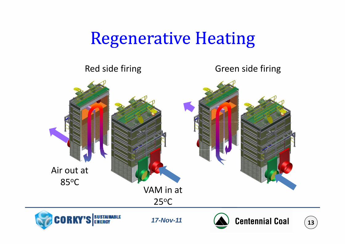
Regenerative HeatingRegenerative HeatingRegenerative Heating Regenerative Heating R d id fi i G id fi iRed side firing Green side firing
Air out at
VAM in at 25oC
85oC
1317-Nov-11

High Thermal MassHigh Thermal MassHigh Thermal MassHigh Thermal MassThe chequer height, hence thermal mass, is approximately 3 times what is required for stable methane concentration operation.
Tall structure leads to low fraction of RAB beingTall structure leads to low fraction of RAB being filled with VAM. The VAM filled portion is between 29 to 34%.
Very slow rise in pressure resulting from a methanespike event due to heat being absorbed by the Chequers low gas turbulence and by the lowChequers, low gas turbulence and by the low VAM fraction of total volume.
No fire observed in duct when operating above LEL
Air filled volumeVAM filled volume
1417-Nov-11

Energy BalanceEnergy Balance3.0
energy per 10 m3/s MWt
Energy BalanceEnergy Balance2 0
2.5
t
energy per 10 m3/s, MWtsupplementary energy, MWtexcess energy, MWt
1.5
2.0
rgy
MW
t gy,electricity, MWe (gross)
0 5
1.0Ener
For example:
0.0
0.5
0 1% 0 3% 0 5% 0 7% 0 9%
300m3/s at 0.6% methaneIs 66.6MWt heat input with 37 2MW potentially recoverable0.1% 0.3% 0.5% 0.7% 0.9%
Methane Content37.2MWt potentially recoverable
1517-Nov-11
Why Potentially Recoverable?Why Potentially Recoverable?3.0
energy per 10 m3/s MWt
Why Potentially Recoverable?Why Potentially Recoverable?2 0
2.5
t
energy per 10 m3/s, MWtsupplementary energy, MWtexcess energy, MWt
Typical methane distribution
1.5
2.0
rgy
MW
t gy,electricity, MWe (gross)
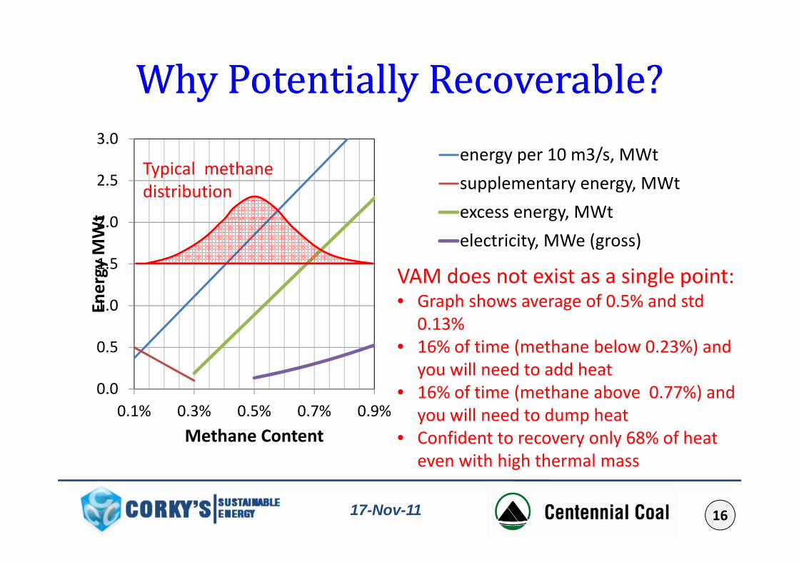
VAM does not exist as a single point:
0 5
1.0Ener VAM does not exist as a single point:
• Graph shows average of 0.5% and std 0.13%
• 16% of time (methane below 0 23%) and
0.0
0.5
0 1% 0 3% 0 5% 0 7% 0 9%
• 16% of time (methane below 0.23%) and you will need to add heat
• 16% of time (methane above 0.77%) and ill d t d h t0.1% 0.3% 0.5% 0.7% 0.9%
Methane Contentyou will need to dump heat
• Confident to recovery only 68% of heat even with high thermal mass
1617-Nov-11
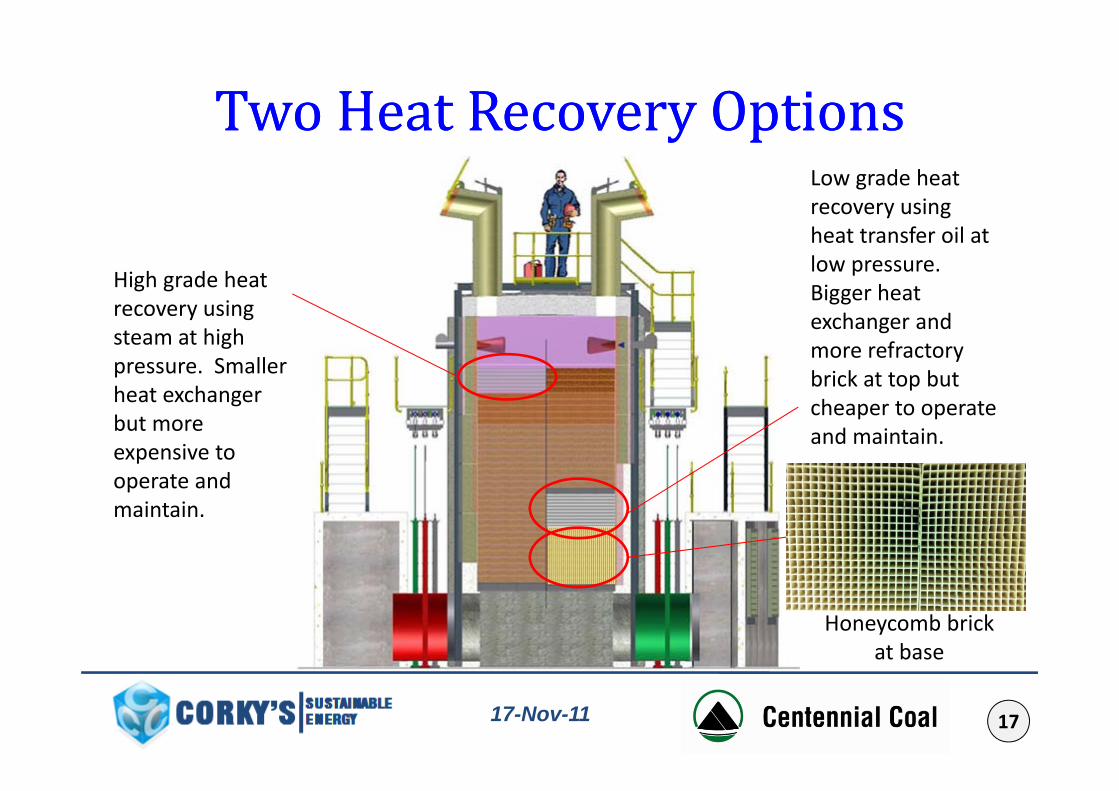
Two Heat Recovery OptionsTwo Heat Recovery OptionsTwo Heat Recovery OptionsTwo Heat Recovery OptionsLow grade heat recovery using y gheat transfer oil at low pressure. Bigger heat High grade heat
recovery using exchanger and more refractory brick at top but
recovery using steam at high pressure. Smaller heat exchanger cheaper to operate
and maintain.
heat exchanger but more expensive to operate andoperate and maintain.
Honeycomb brick at base
1717-Nov-11
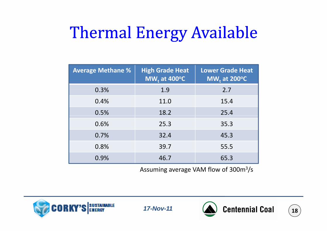
Thermal Energy AvailableThermal Energy AvailableThermal Energy AvailableThermal Energy AvailableAverage Methane % High Grade Heat
MWt at 400oCLower Grade Heat
MWt at 200oC
0 3% 1 9 2 70.3% 1.9 2.7
0.4% 11.0 15.4
0.5% 18.2 25.4
0.6% 25.3 35.3
0.7% 32.4 45.3
0.8% 39.7 55.5
0.9% 46.7 65.3
A i VAM fl f 300 3/Assuming average VAM flow of 300m3/s
1817-Nov-11

Connection to MineConnection to Mine -- ScopeScopeConnection to Mine Connection to Mine ScopeScopeProposed Solution• Passive safety design where combustion is in the chequersy g q• Have five independent layers of protection• Three layers to stop VAM spike reaching RAB• Two layers to stop deflagration flashback reaching mine fanTwo layers to stop deflagration flashback reaching mine fan• Solution is scalable to full commercial implementation• Independent layers mutually supportive
eg barriers work in both directioneg. barriers work in both directioneg. dilution door also act as pressure relief
ibl
Bypass
Frangible Pressure Relief System
Bypass System
Dilution System
1917-Nov-11

Connection to MineConnection to Mine CHCH measurementmeasurementConnection to Mine Connection to Mine –– CHCH44 measurementmeasurementMineMine
ventilation fan
10 m3/s along 4 m duct of CSA 1.5m2ILP 2 and 5 10 m /s along 4 m duct of CSA 1.5mVelocity along duct 6.6 m/s10 m3/s along 10 m duct of CSA 3.0m2
Velocity along duct 3.3 m/s
ILP 2 and 5 O2 sil 2
ILP 1 CH4 sil 2
y g /Warning time: 0.6+3.0 = 3.6 seconds
ILP 2 CH4 sil 2
ILP 4 CH4 sil 2
310 m3/s up a 240 m shaft of diameter 5.5mVelocity up shaft 13.0 m/sWarning time 18.4 seconds
2017-Nov-11
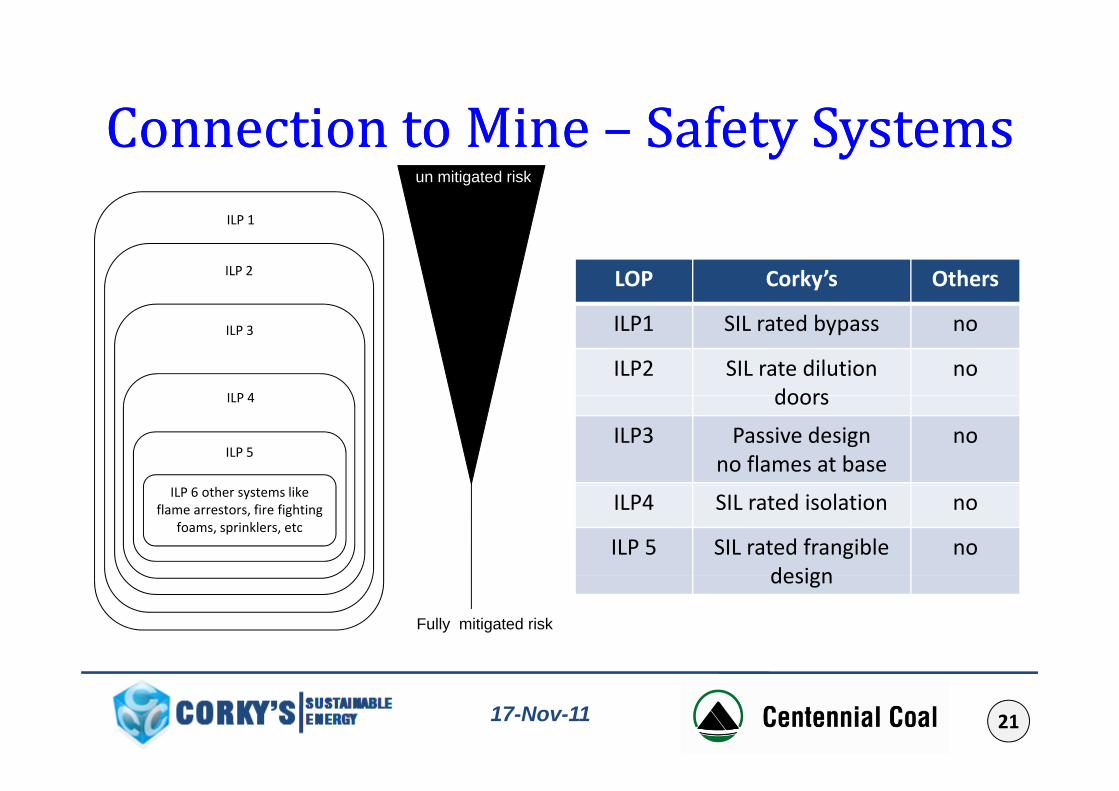
Connection to MineConnection to Mine Safety SystemsSafety SystemsConnection to Mine Connection to Mine –– Safety SystemsSafety SystemsILP 1
un mitigated risk
ILP 1
ILP 2 LOP Corky’s Others
ILP 3
ILP 4
ILP1 SIL rated bypass no
ILP2 SIL rate dilution doors
noILP 4
ILP 5
doors
ILP3 Passive design no flames at base
no
ILP 6 other systems like flame arrestors, fire fighting
foams, sprinklers, etcILP4 SIL rated isolation no
ILP 5 SIL rated frangible design
no
Fully mitigated risk
design
2117-Nov-11
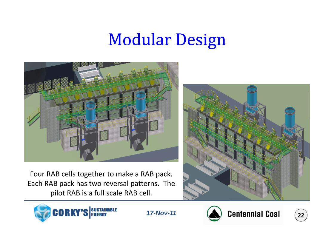
Modular DesignModular DesignModular DesignModular Design
F RAB ll h k RAB kFour RAB cells together to make a RAB pack. Each RAB pack has two reversal patterns. The
pilot RAB is a full scale RAB cell.
2217-Nov-11

How is Four Pack Different to How is Four Pack Different to D t ti Pl tD t ti Pl tDemonstration PlantsDemonstration PlantsA four pack has:p
• Lower cost per volume of VAM abated.
• Less heat lost due to reduced surface area per reaction volume. Therefore will work better at 0.3%.
• More surface area in bottom half and this will result lower exhaust temperature. Therefore it will work better at 0.3%
• More refractory mass per reaction volume. Therefore more steady operation.p
• And is designed for low grade heat recovery (fitting HE is optional)
2317-Nov-11
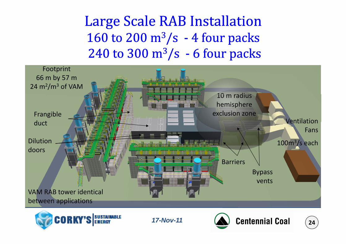
Large Scale RAB Installation Large Scale RAB Installation 160 to 200 m160 to 200 m33/s/s -- 4 four packs4 four packs160 to 200 m160 to 200 m /s /s -- 4 four packs4 four packs240 to 300 m240 to 300 m33/s /s -- 6 four packs6 four packsF i
10 di
Footprint 66 m by 57 m
24 m2/m3 of VAM10 m radius hemisphere
exclusion zoneVentilation
Frangible duct
Dilution doors
Ventilation Fans
100m3/s each
duct
Barriers
doors
Bypass vents
VAM RAB tower identical between applications
2417-Nov-11
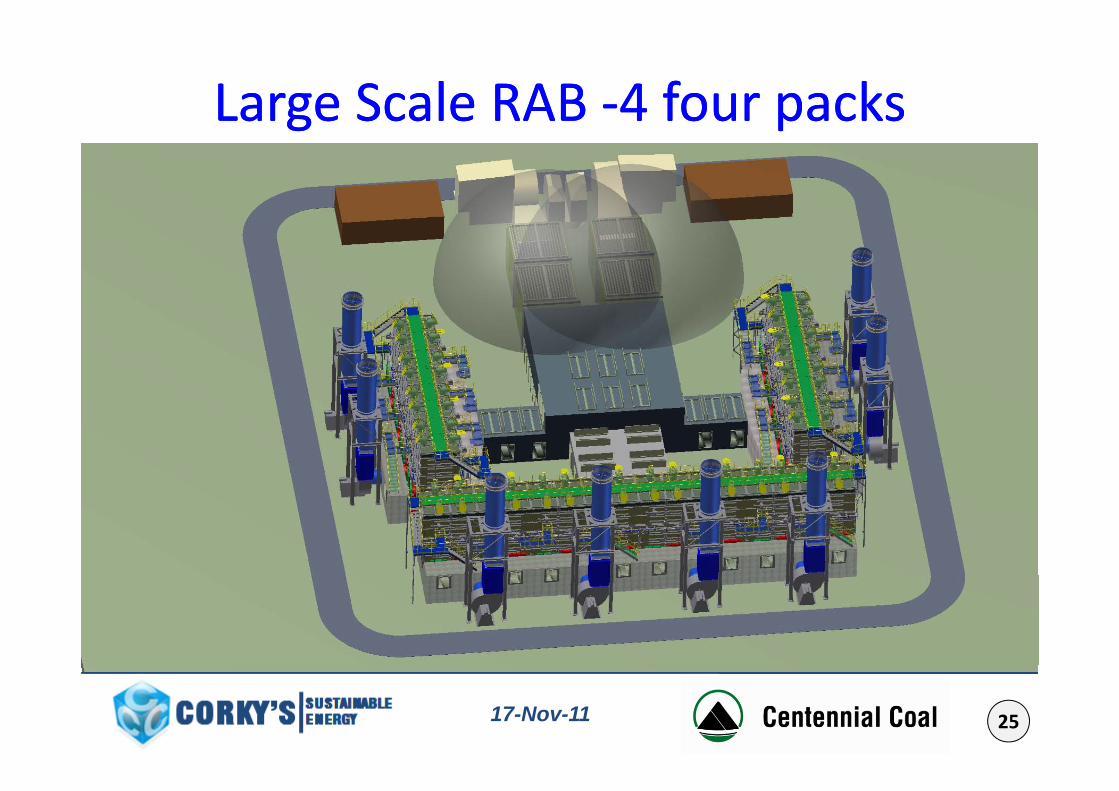
Large Scale RAB Large Scale RAB --4 four packs4 four packsgg pp
Dilution doors
Dilution doors
Dilution doors
Vent Louvers
Frangible
Frangible duct
doors duct Frangible duct
Isolation Louvers/ curtains
2517-Nov-11
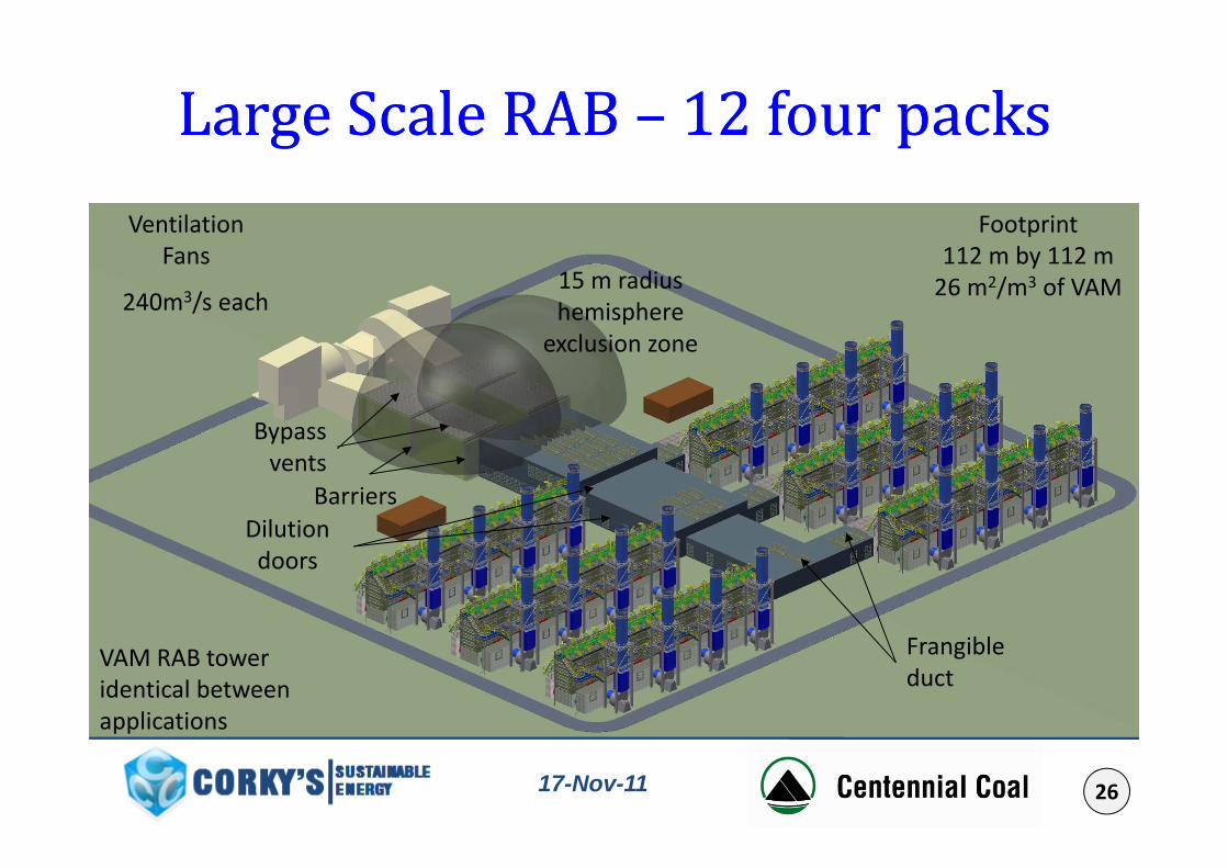
Large Scale RAB Large Scale RAB –– 12 four packs12 four packsgg ppFootprint Ventilation
15 m radius hemisphere
l i
112 m by 112 m26 m2/m3 of VAM
Fans
240m3/s eachexclusion zone
Bypass
BarriersDilution
Bypass vents
Dilution doors
Frangibleduct
VAM RAB tower identical between applications
2617-Nov-11
pp
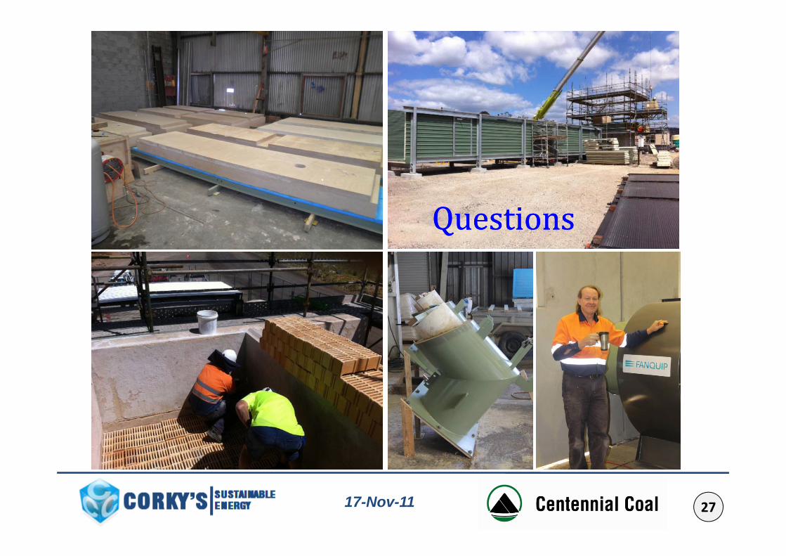
QuestionsQuestionsQuestionsQuestions
2717-Nov-11