core analysis of portland cement concrete slip formed barriers · core analysis of portland cement...
TRANSCRIPT
CORE ANALYSIS OF PORTLAND CEMENT CONCRETE
SLIP FORMED BARRIERS
Final ReportFor
MLR-98-4
January 2000
Highway Division
Iowa Departmentof Transportation

Core Analysis ofPortland Cement Concrete
Slip Formed Barriers
Final Reportfor
MLR-98-4
ByRobert Steffes
Assistant to the Research Engineer515-239-1392
FAX 515-239-1092and
Todd HansonP.C. Concrete Engineer
515-239-1226FAX 515-239-1092Office of Materials
Project Development DivisionIowa Department of Transportation
Ames, Iowa 50010
January 2000

TECHNICAL REPORT DOCUMENTATION PAGE
1. REPORT NO. 2. REPORT DATE
MLR-98-4 January 2000 3. TITLE & SUBTITLE 4. TYPE OF REPORT & PERIOD COVERED
Core Analysis of Portland Cement Concrete Final Report, 10-98 to 9-99Slip Formed Barriers
5. AUTHOR(S) 6. PERFORMING ORGANIZATION ADDRESS
Robert Steffes Iowa Department of TransportationAssistant to the Research Engineer Materials Department and 800 Lincoln WayTodd Hanson Ames, Iowa 50010P.C. Concrete Engineer 7.
ACKNOWLEDGMENT OF COOPERATING ORGANIZATIONS
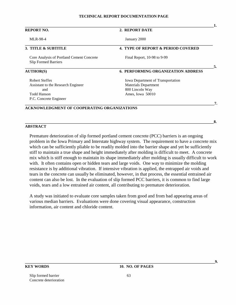
8. ABSTRACT
Premature deterioration of slip formed portland cement concrete (PCC) barriers is an ongoingproblem in the Iowa Primary and Interstate highway system. The requirement to have a concrete mixwhich can be sufficiently pliable to be readily molded into the barrier shape and yet be sufficientlystiff to maintain a true shape and height immediately after molding is difficult to meet. A concretemix which is stiff enough to maintain its shape immediately after molding is usually difficult to workwith. It often contains open or hidden tears and large voids. One way to minimize the moldingresistance is by additional vibration. If intensive vibration is applied, the entrapped air voids andtears in the concrete can usually be eliminated, however, in that process, the essential entrained aircontent can also be lost. In the evaluation of slip formed PCC barriers, it is common to find largevoids, tears and a low entrained air content, all contributing to premature deterioration.
A study was initiated to evaluate core samples taken from good and from bad appearing areas ofvarious median barriers. Evaluations were done covering visual appearance, constructioninformation, air content and chloride content.
9. KEY WORDS 10. NO. OF PAGES
Slip formed barrier 63Concrete deterioration


TABLE OF CONTENTS
Page
Introduction . . . . . . . . . . . . . . . . . . . . . . . . . . . . . . . . . . . . . . . . . . . . . . . . . . . . . . . . . . . . . . 1
Objective . . . . . . . . . . . . . . . . . . . . . . . . . . . . . . . . . . . . . . . . . . . . . . . . . . . . . . . . . . . . . . . . 1
Project Sites . . . . . . . . . . . . . . . . . . . . . . . . . . . . . . . . . . . . . . . . . . . . . . . . . . . . . . . . . . . . . . 1
Core Descriptions . . . . . . . . . . . . . . . . . . . . . . . . . . . . . . . . . . . . . . . . . . . . . . . . . . . . . . . . . . 1
Results . . . . . . . . . . . . . . . . . . . . . . . . . . . . . . . . . . . . . . . . . . . . . . . . . . . . . . . . . . . . . . . . . . 1
Conclusion . . . . . . . . . . . . . . . . . . . . . . . . . . . . . . . . . . . . . . . . . . . . . . . . . . . . . . . . . . . . . . . 2
Implementation . . . . . . . . . . . . . . . . . . . . . . . . . . . . . . . . . . . . . . . . . . . . . . . . . . . . . . . . . . . 3
Acknowledgment . . . . . . . . . . . . . . . . . . . . . . . . . . . . . . . . . . . . . . . . . . . . . . . . . . . . . . . . . . 3
AppendicesAppendix A - MLR Proposal . . . . . . . . . . . . . . . . . . . . . . . . . . . . . . . . . . . . . . . . . . . . . 4Appendix B - Concrete Median Barrier Standard Plan . . . . . . . . . . . . . . . . . . . . . . . . . 8Appendix C - Project Sites, Contractors and Field Notes . . . . . . . . . . . . . . . . . . . . . . 10Appendix D - Core Descriptions . . . . . . . . . . . . . . . . . . . . . . . . . . . . . . . . . . . . . . . . . 44Appendix E - Core Photos . . . . . . . . . . . . . . . . . . . . . . . . . . . . . . . . . . . . . . . . . . . . . . 46Appendix F - Core Analysis Tables . . . . . . . . . . . . . . . . . . . . . . . . . . . . . . . . . . . . . . . 58Appendix G - New Mix Design for Concrete Barrier Rail . . . . . . . . . . . . . . . . . . . . . . 61
DISCLAIMER
The contents of this report reflect the views of theauthor and do not necessarily reflect the officialviews of the Iowa Department of Transportation.This report does not constitute any standard,specification or regulation.


1
INTRODUCTION
Some PCC median barriers showed signs of having less than desirable qualities in appearance anddurability. To achieve the desired molded shape, excessive vibration was often applied to a stiffconcrete mix. The finished product was sometimes a barrier with large entrapped air voids, tears andlow entrained air content, all contributing to premature deterioration. A Materials LaboratoryResearch proposal, MLR-98-4 (see Appendix A) was set up to evaluate the problem.
OBJECTIVE
The objective of the research is to evaluate existing PCC median barriers and to find procedures,materials and mix designs which will result in a better appearing, more workable and more durablePCC slip formed median barrier.
PROJECT SITES
The sites for taking median barrier core samples were selected to cover four different constructionprojects. They were all from Interstate routes in Polk County (see Appendix C). With carefulobservations in the field, the exact location of the core sampling sites may be visible by the evidenceof filled core holes.
CORE DESCRIPTIONS
Cores were taken from the median barrier of I-80 in Polk County, October 1998. The coredescription, “bad,” means there was significant visual appearance of barrier surface deterioration,i.e., cracking, staining and leachate deposits. The core description, “good,” means there was novisual appearance of deterioration on the barrier surface.
The arrow on the face of each core points to the top position. This position was marked to determineif core voids, cracks or tears show a relevance to direction of paving.
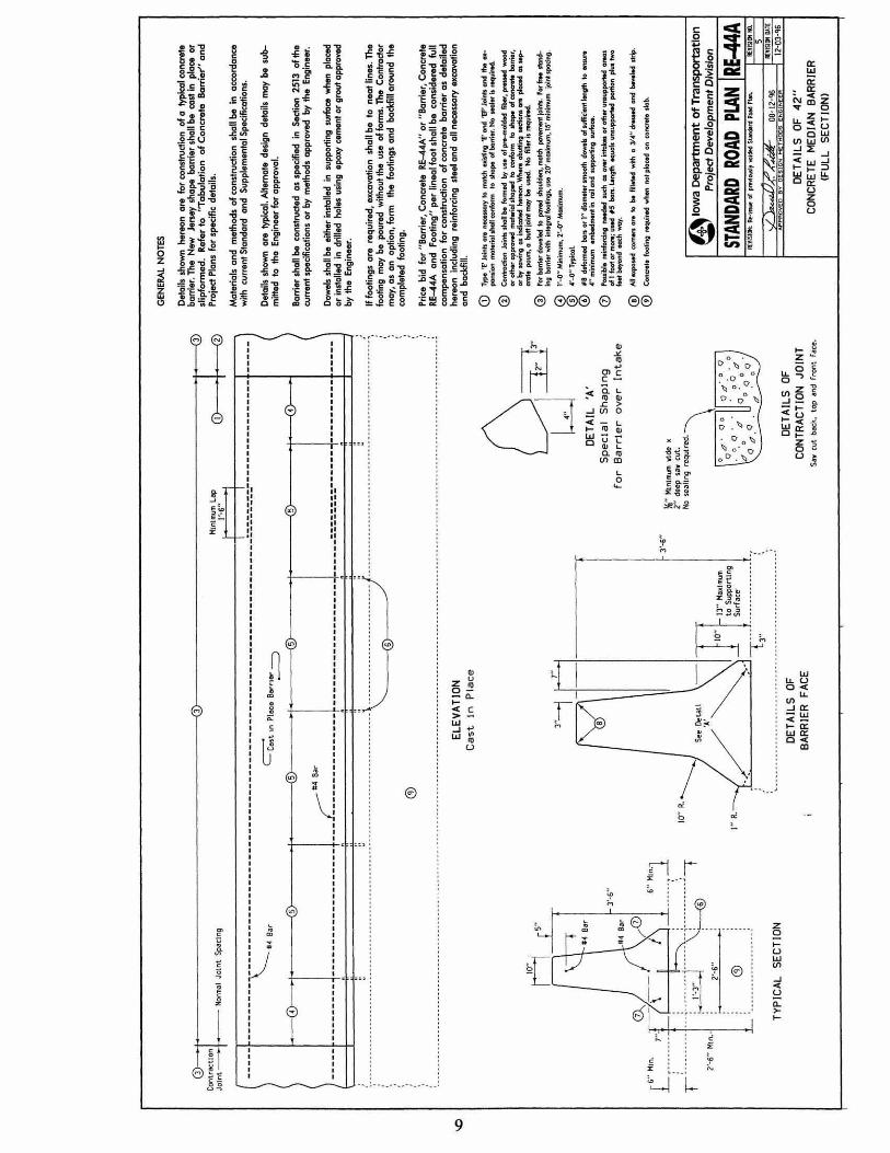
The core sites were selected such that no reinforcing steel should be hit by the coring bit (seeAppendix B).
RESULTS
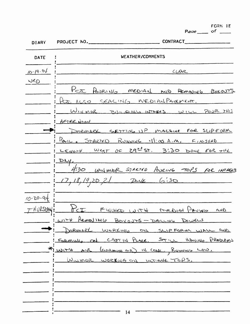
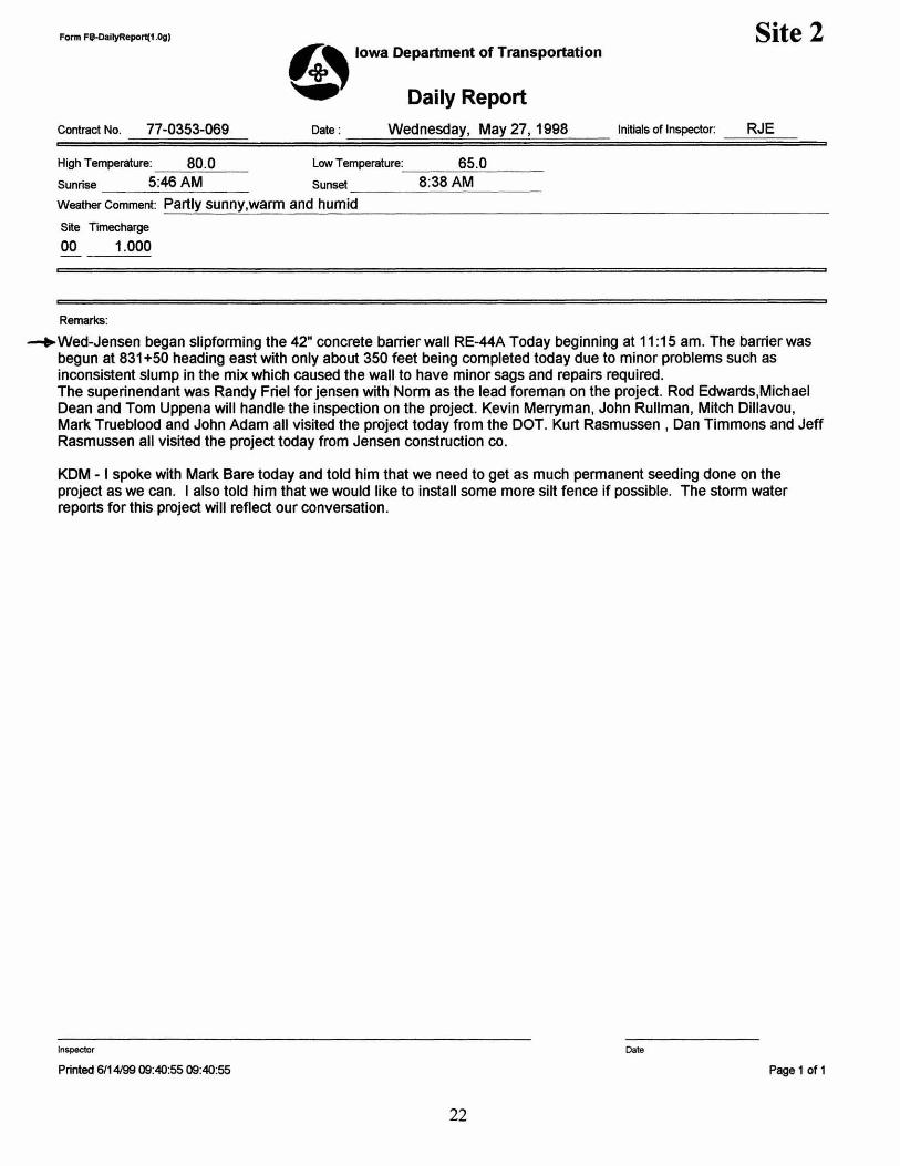
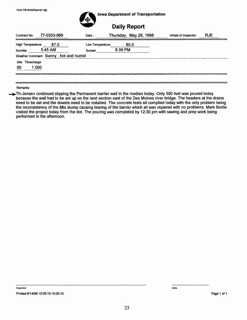
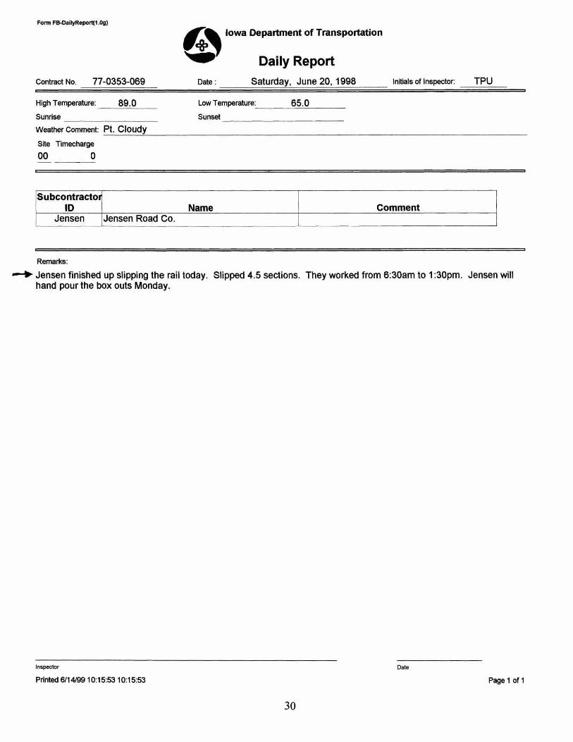
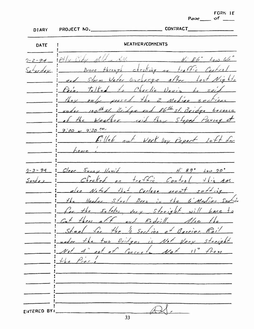
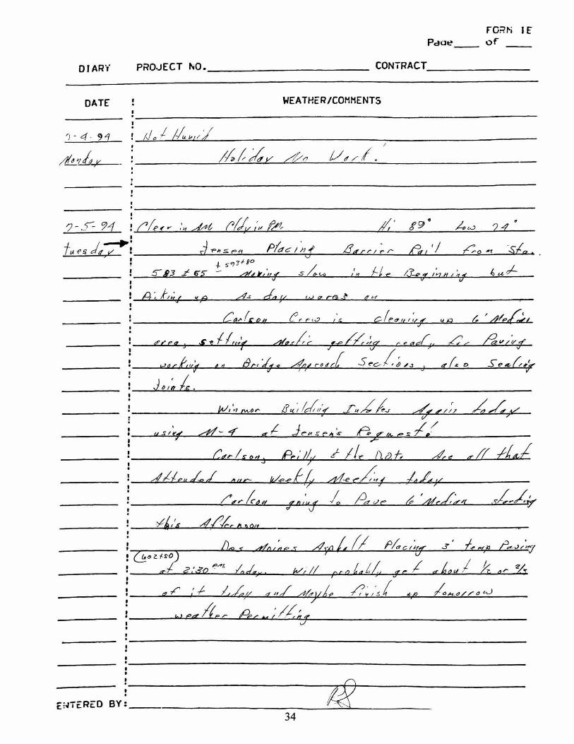
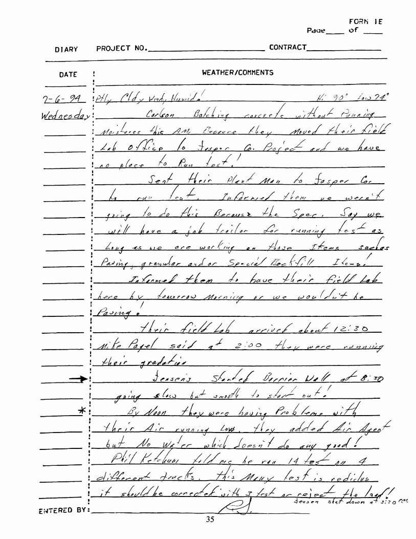
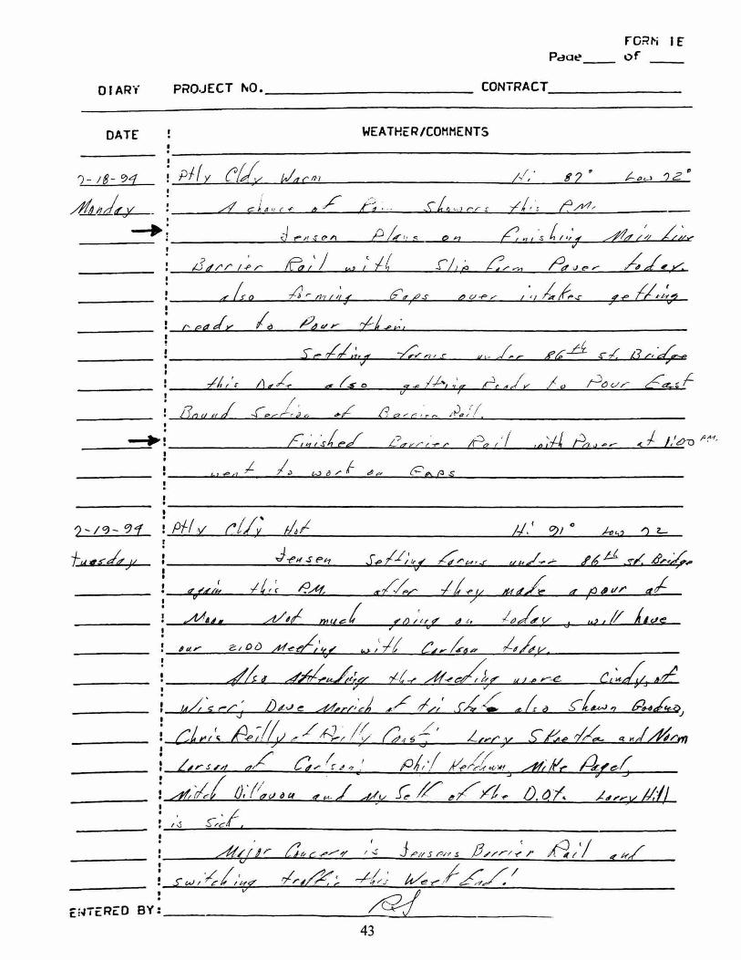
The search for information and construction history for the selected sites gave limited success. Themajority of information came from field book notes which often gave minimal details. For projectsites, mainly 1 and 3, air content problems were recorded a number of times (see project diary and
2
daily reports, Appendix C).
The visual appearance of some cores showed major voids or tears within the concrete as a result ofconstruction workability, consolidation or mix design problems (see photos, Appendix E).
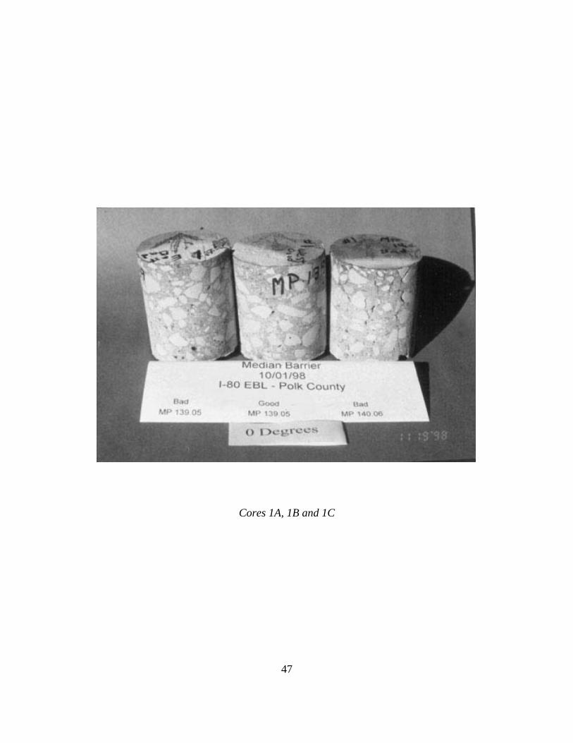
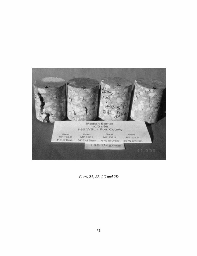
The results of coring from some areas of barriers with a bad appearing surface showed no significant“bad” problem deeper into the barrier. Examples are core photos 1A and 1C. In other cases, largevoids or tears were exposed during coring which were not detectable from surface visualexaminations (see core photos 2A and 2B). The concrete in core 4B was so deteriorated that it couldnot be prepared for laboratory analysis. The air system for most cores was found to be acceptableexcept for core 1A (see appendix F).
From the differences in core conditions and surface appearances found, it can be seen that there isa wide range and somewhat unpredictable quality of concrete to be found in the barriers.
CONCLUSION
As a result of the study of median barrier quality problems, a significant amount of work has beendone to change the mix design to something which would be more suitable for slip formed barrierapplications.
The standard Iowa DOT D-57 mix design has typically been used in slip formed barrier rails. Thismix has a high amount of paste and fines, having a cement content of 709 lbs./cu. yd., with 50%coarse aggregate and 50% sand. The typical combined gradation produces a gap-graded aggregatestructure and in conjunction with the high paste content it produces a very stiff unworkable mix.
In 1999, slip formed barrier rails were being placed on the dual bridges over the railroad on relocatedUS 18 in Floyd County, near Rudd. The contractor, Allied Construction, called in with problemsconcerning entraining air in the D-57 mix. The D-57 mix is typically placed at 3/4 in. slump makingit difficult to entrain air. The producer had been using 25 oz./cwt of air entraining agent and wasable to achieve only 5.5% plastic air content. It was decided to investigate the use of well-gradedaggregates in conjunction with a reduced cement content to facilitate placement and air entrainingof the concrete.
The new mix design for the concrete barrier rail (BR) utilized well-graded aggregates through theincorporation of ¼" (6.35 mm) chips and a reduced cement content of 603 lbs./cu. yd. This mixrequired only 8 oz./cwt of air entraining agent to achieve 7.4 % plastic air content. They were alsoable to increase the slump to 1 in. and rate of placement was increased.
Since this project, the BR mix was included in the standard specifications. In the fall of 1999, it wasused on a median barrier on I-35/80 in Des Moines from Merle Hay Road to the 2nd Avenueinterchange. The BR mix design achieved better placement characteristics and air entraining
3
capacity than the D-57 mix design.
Additional design adjustments may be needed as material and construction conditions vary. Frominitial applications, the new mix design appears to be a significant improvement over previously usedmix designs. The new mix design specification for BR is now being applied (see Appendix G). Atthis time, no specific recommendations for changes in vibration energy applied or configuration ofvibrators will be made.
IMPLEMENTATION
A major effort has already been put into place to develop a new concrete mix especially designedfor use in slip formed barriers. Initial use of the new mix occurred in 1999 in bridge barrier rails inFloyd County on US 18 and in median barriers in Polk County on I-35/80.
The new mix design was already found to be easier to work with and will result in a better finishedproduct.
ACKNOWLEDGMENT
Sincere thanks and appreciation goes to the Special Investigation personnel for their support toobtain core samples and to the Cement and Concrete personnel for their support in the core analysis.


4
APPENDIX AMLR Proposal


5
DATE: October 28, 1998
PROJECT: MLR-98-4
TITLE: Core Analysis of Slip Formed Barriers
PRINCIPAL INVESTIGATOR: Todd Hanson and Bob Steffes
OBJECTIVE: The objective of this research is to determine the air content and void system of
low slump Portland cement concrete (PCC) slip formed median barriers in search
of causes of premature concrete deterioration.
DISCUSSION: In some areas of some slip formed barrier projects, premature deterioration
appears to be occurring. Extensive surface cracking and growth of leachate
deposits become visible on the barrier surface within a few years after
construction. To slipform a barrier, a relatively dry, stiff mix of concrete is
required and extensive vibration is used to facilitate concrete consolidation and
forming. It is assumed that an inappropriate mix design for the application and/or
excessive vibration may be contributing to the premature deterioration.
PURPOSE: The purpose of this study is to determine if adjustments in mix design, vibration
for consolidation or construction techniques could be made which would result
in an improved appearance and durability of slip formed PCC barriers.
PROCEDURE: Cores will be taken from median barriers from four different paving projects on
I-80 and I-80/I-35 in Polk County. Core sites will be selected to include areas
with no visible deterioration and sites which show extensive deterioration. The
cores will be 4" diameter and approximately 5" long, perpendicular to the barrier
face. They will be taken approximately 30" above the roadway surface.
6
ANALYSIS: The core analysis will include chloride content at various depths, and a detailed
determination of the air void system.
The chloride contents will be checked at 0.5", 1", and 2" intervals using the
Phillips XRF. Samples will be analyzed for elemental chlorine (Cl) and used to
estimate the amount per cubic yard.
Air content will be checked at 0.5" and 1" intervals using the Hitachi low vacuum
SEM in conjunction with an image analysis program. The air content (%),
specific surface (α), and spacing factor (L) will be calculated at each depth.
Records of concrete mixes used and construction logs will be evaluated, if core
analysis results are found to be abnormal.
RESPONSIBILITIES: Projects for evaluation will be selected by the Portland Cement
Pavement Engineer.
Specific sites for cores will be selected by the Materials Research
personnel.
Coring will be done by Special Investigations personnel.
Analysis of cores and summation of results will be done by the
Technical Services Engineer.
IMPLEMENTATION: The findings from this study will lead to:
1) Improvements in the concrete mix design, workability, durability and
appearance of the barriers.
2) Improved consolidation while still maintaining desired entrained air
content.

7
REPORTING: The final report will be coauthored by Todd Hanson and Bob Steffes.

8
APPENDIX BConcrete Median Barrier Standard Plan


10
APPENDIX CProject Sites, Contractors and Field Notes


11
PROJECT SITES, CONTRACTORS AND FIELD NOTES
Site 1 Site Location:I-80 East bound laneMP 139.05, MP 140.06Paved west to eastUsed D-571994
Contractor:Dormark Construction CompanyP.O. Box 520 303 S 2nd StreetGrimes, IA 50111515-986-4270
Field Notes:See pages 13-22
Site 2 Site Location:I-35/I-80 West bound laneMP 132.90Paved west to eastUsed D-57-C20 & D-57-C101998
Contractor:Jensen Road CompanyBox 33455550 NE 22nd StreetDes Moines, IA 50316515-266-5173
Field Notes:See pages 23-31

12
PROJECT SITES, CONTRACTORS AND FIELD NOTES, Continued
Site 3 Site Location:I-35/I-80 West bound laneMP 128.25Paved west to eastUsed D-57 & D-57-6-C1994
Contractor:Jensen Road CompanyBox 33455550 NE 22nd StreetDes Moines, IA 50316515-266-5173
Field Notes:See pages 32-43
Site 4 Site Location:I-35/I-80 South bound laneMP 126.50Files have been purgedPaved south to north
Contractor:United Contractors Inc.P.O. Box 3476678 N W 62nd AvenueJohnston, IA 50131515-276-6162
Field Notes:Field notes were purged


44
APPENDIX DCore Descriptions


45
POLK COUNTY PROJECT SITESAND
CORE DESCRIPTIONS
Core 1A, I-80, EBLMP 139.05, 20 ft. west - BAD
Core 1B, I-80, EBLMP 139.05, 70 ft. west - GOOD
Core 1C, I-80, EBLMP 140.06 - BAD
Core 2A, I-35, I-80, WBLMP 132.9, 4 ft. east of drain panel - GOOD
Core 2B, I-35, I-80, WBLMP 132.9, 54 ft. east of drain panel - GOOD
Core 2C, I-35, I-80, WBLMP 132.9, 4 ft. west of drain panel - GOOD
Core 2D, I-35, I-80, WBLMP 132.9, 24 ft. west of drain panel - GOOD
Core 3A, I-35, I-80, WBLMP 128.25 - GOOD
Core 4A, I-35, I-80, SBLMP 126.5 - GOOD
Core 4B, I-35, I-80, SBLMP 126.5 - BAD


46
APPENDIX ECore Photos

47
Cores 1A, 1B and 1C

48
Barrier showing sites (dark 4" diameter circle) for core 1A

49
Barrier showing site (dark 4" diameter circle) for core 1B
50
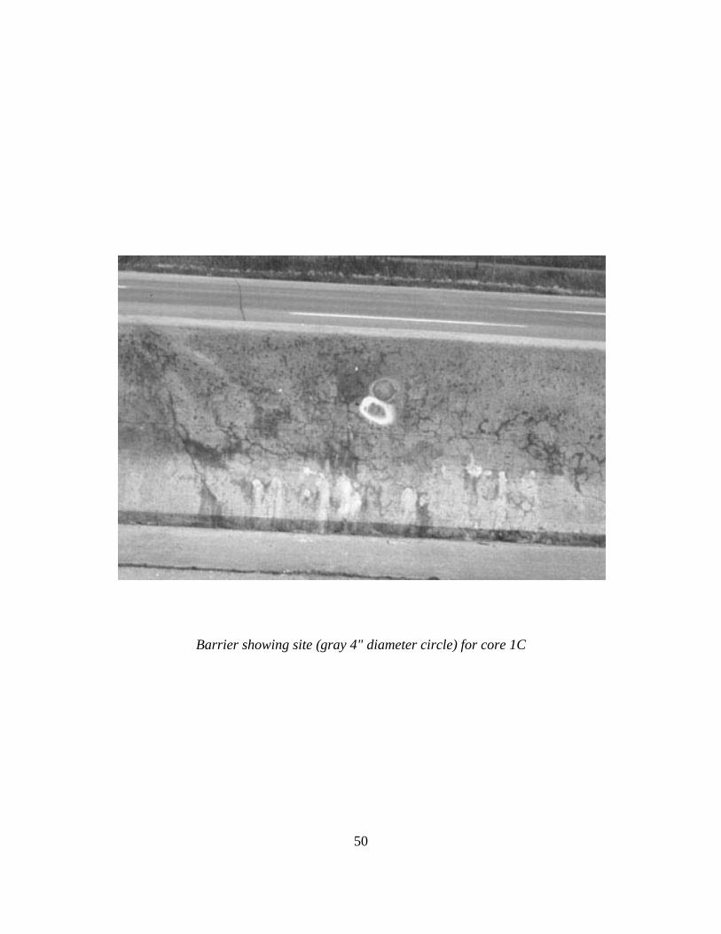
Barrier showing site (gray 4" diameter circle) for core 1C
51
Cores 2A, 2B, 2C and 2D

52
Barrier showing site (dark 4" diameter circle) for cores 2A and 2C

53
Core 3A

54
Barriers showing site (dark 4" diameter circle) for core 3A

55
Cores 4A and 4B
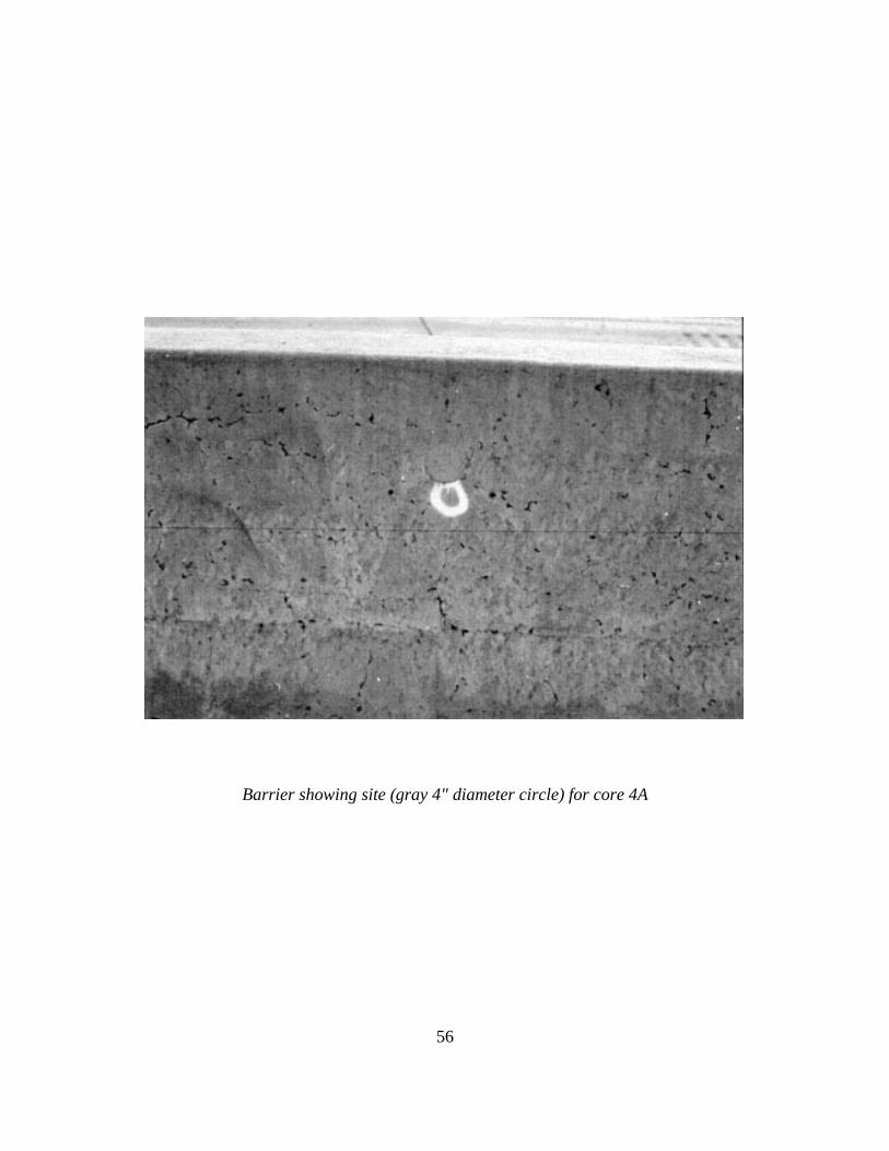
56
Barrier showing site (gray 4" diameter circle) for core 4A

57
Barrier showing site (dark 4" diameter circle) for core 4B


58
APPENDIX FCore Analysis Tables

59
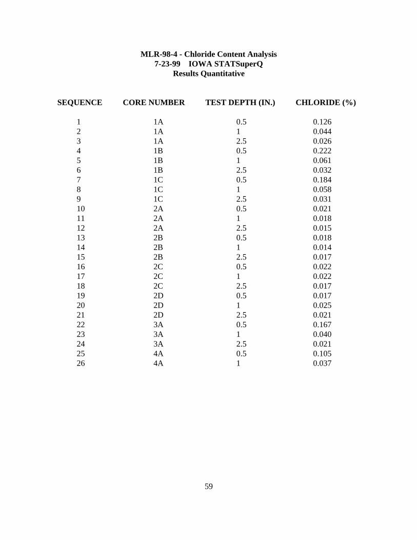
MLR-98-4 - Chloride Content Analysis7-23-99 IOWA STATSuperQ
Results Quantitative
SEQUENCE CORE NUMBER TEST DEPTH (IN.) CHLORIDE (%)
1 1A 0.5 0.1262 1A 1 0.0443 1A 2.5 0.0264 1B 0.5 0.2225 1B 1 0.0616 1B 2.5 0.0327 1C 0.5 0.1848 1C 1 0.0589 1C 2.5 0.03110 2A 0.5 0.02111 2A 1 0.01812 2A 2.5 0.01513 2B 0.5 0.01814 2B 1 0.01415 2B 2.5 0.01716 2C 0.5 0.02217 2C 1 0.02218 2C 2.5 0.01719 2D 0.5 0.01720 2D 1 0.02521 2D 2.5 0.02122 3A 0.5 0.16723 3A 1 0.04024 3A 2.5 0.02125 4A 0.5 0.10526 4A 1 0.037

61
APPENDIX GNew Mix Design for Concrete Barrier Rail


