copyright prentice-hall chapter 23 machining processes used to produce round shapes: turning and...
TRANSCRIPT

Copyright Prentice-Hall
Chapter 23Machining Processes Used to Produce Round
Shapes: Turning and Hole Making

Lathe Cutting Operations
Miscellaneous cutting operations that can be performed on a lathe. Note that all parts are circular – a property known as axisymmetry. The tools used, their shape, and the processing parameters are described throughout this chapter.
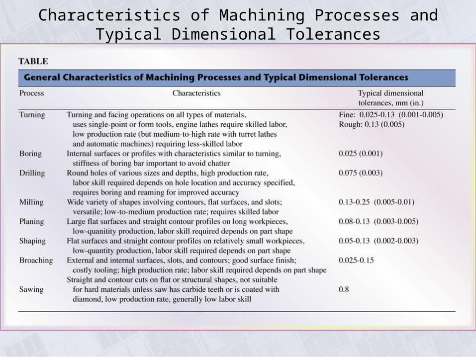
Characteristics of Machining Processes and Typical Dimensional Tolerances

Lathe
General view of a typical lathe, showing various components. Source: Courtesy of Heidenreich & Harbeck.

Turning Operation
Schematic illustration of the basic turning operation, showing depth-of-cut, d; feed, f; and spindle rotational speed, N in rev/min. Cutting speed is the surface speed of the workpiece at the tool tip.
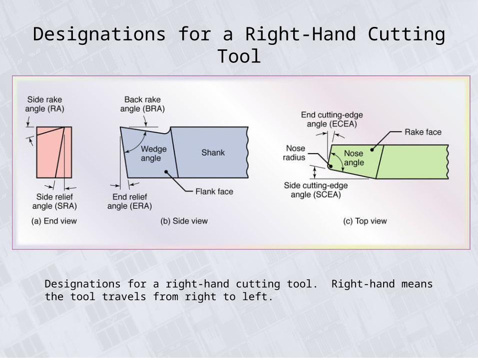
Designations for a Right-Hand Cutting Tool
Designations for a right-hand cutting tool. Right-hand means the tool travels from right to left.

General Recommendations for Tool Angles in Turning

Summary of Turning
Parameters and Formulas

Forces Acting on a Cutting Tool in Turning
Forces acting on a cuttin tool in turning, Fc is the cutting force, Ft is the thrust of feed force (in the direction of feed), and Fr is the radial force that tends to push the tool away from the workpiece being machined.

Range of Applicable Cutting Speeds and Feeds for Tool Materials
Figure 23.6 The range of applicable cutting speeds and feeds for a variety of tool materials.

Typical Capacities and Maximum Workpiece Dimensions for Machine Tools

Collets
(a) and (b) Schematic illustrations of a draw-in type collet. The workpiece is placed in the collet hole, and the conical surfaces of the collet are forced inwards by pulling it with a draw bar into the sleeve. (c) A push-out type collet. (d) Workholding of a workpiece on a face plate.

Mandrels to Hold Workpieces for Turning
Figure 23.8 Various types of mandrels to hold workpieces for turning. These mandrels usually are mounted between centers on a lathe. Note that in (a), both the cylindrical and the end faces of the workpiece can be machined, whereas in (b) and (c), only the cylindrical surfaces can be machined.

Turret Lathe
Schematic illustration of the components of a turret lathe. Note the two turrets: square and hexagonal (main).
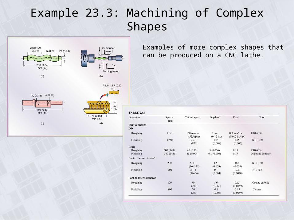
Example 23.3: Machining of Complex Shapes
Examples of more complex shapes that can be produced on a CNC lathe.

Typical Production Rates for Various
Machining Operations

Range of Surface Roughnesses in
Machining Processes
The range of surface roughnesses obtained in various machining processes. Note the wide range within each group, especially in turning and boring.

Range of Dimensional Tolerances in
Machining as a Function of
Workpiece Size
Range of dimensional tolerances obtained in various machining processes as a function of workpiece size. Note that there is an order os magnitude difference between small and large workpieces.

Troubleshooting Guide for Turning

Boring and Boring Mill
(a) Schematic illustration of a steel boring bar with a carbide insert. Note the passageway in the bar for cutting fluid application. (b) Schematic illustration of a boring bar with tungsten-alloy “inertia disks” sealed in the bar to counteract vibration and chatter during boring. This system is effective for boring bar length-to-diameter ratios of up to 6.
Schematic illustration of a vertical boring mill. Such a machine can accommodate workpiece sizes as large as 2.5m (98 in.) in diameter.

General Capabilities of Drilling
Figure 23.20 Various types of drills and drilling and reaming operations.

Types of Drills
Figure 23.21 Various types of drills.

Trepanning
Figure 23.23 (a) Trepanning tool. (b) Trepanning with a drill-mounted single cutter.

General Recommendations for Speeds and Feeds in Drilling

Troubleshooting Guide for Drilling

Three-Axis Computer Numerical-Control Drilling Machine
A three-axis computer numerical-control drilling machine. The turret holds as many as eight different tools, such as drills, taps, and reamers.

Helical Reamer and Inserted-Blade Adjustable Reamer
(a) Terminology for a helical reamer. (b) Inserted-blade adjustable reamer.

Tapping
(a) Terminology for a tap. (b) Tapping of steel nuts in production.