copyright © mikroelektronika, december 2011. all rights ... · dvd or download it from the...
TRANSCRIPT

Copyright © mikroElektronika, December 2011. All rights reserved.

Page 2 Page 3
mikroPascal PRO for ARM® organizes
applications into projects consisting of a
single project file (file with the .mppar
extension) and one or more source files (files
with the .c extension). The mikroPascal PRO
for ARM® compiler allows you to manage
several projects at a time. Source files can be
compiled only if they are part of the project.
In this reference guide, we will create a new
project, write code, compile it and test the
results. The purpose of this project is to make
microcontroller PORTA LEDs blink, which will
be easy to test.
A project file contains:
• Project name and optional description;
• Target device in use;
• Device clock;
• List of the project source files;
• Binary files (*.emcl); and
• Other files.
1. Introduction to mikroPascal PRO for ARM
05
06
07
01 04 07
02 05 08
03 06
Main Toolbar
Code Explorer
Project Settings
Messages
Code Editor
Image Preview
Project Manger
Library Manager
03
02
04
01
08

Page 2 Page 3
Let’s make a simple “Hello world” example for the
selected microcontroller. First thing embedded
programmers usually write is a simple LED blinking
program. So, let’s do that in a few simple lines of
Pascal code.
LED blinking is just turning ON and OFF LEDs that
are connected to desired PORT pins. In order to see
the example in action, it is necessary to connect
the target microcontroller according to schematics
shown on Figure 2-1. In the project we are about
to write, we will use only PORTA, so you should
connect the LEDs to PORTA only.
Prior to creating a new project, it is necessary to do the following:
Step 1: Install the compilerInstall the mikroPascal PRO for ARM® compiler from the Product DVD or download it from the MikroElektronika website:
http://www.mikroe.com/eng/products/view/753/mikroPascal-pro-for-arm/
Step 2: Start up the compilerDouble click on the compiler icon in the Start menu, or on your desktop
to Start up the mikroPascal PRO for ARM® compiler. The mikroPascal
PRO for ARM® IDE (Integrated Development Environment) will appear
on the screen. Now you are ready to start creating a new project.
2. Hardware ConnectionVCC-3.3
AVCC
30292827 3433
58575655545352
463635 42 43 44 4537 50
9
48 49
1112
32
72
69686766656463
43
78 77
2423
181716151413
5678
10
7980
12
22212019
62616059
38 39 40 41 47
71
31
51
70
26
25
76
757473
LM3S9B95
81828384858687888990919293949596979899100
PA
7P
A6
ER
BIA
SV
DD
PF4
PF5
PE5PE4LDOVDD
GNDVDD
PB1/USB0VBUS
VDD
VD
DTX
OP
PJ4PJ5PJ6PJ7
GN
DTX
ON
PB
5P
B6
PB
7
VD
D
VD
DC
PJ1
PH
2P
H3
GNDAVDDA
PD
5P
D4
PE
3P
E2
GN
D
PB
4
PD2
PA
2
PC6PC7GNDVDDPG0PG1
USB0DPUSB0DM
NC
PB3/I2C0SDA
PJ0
PD1PD0
VD
DC
PD
6P
D7
PE7PE6
PA
1P
A0
PC4PC5
OS
C1
PJ3
PB0/USB0ID
PF2
PF0
OS
C0
GND
PJ2
RX
IN
MDIO
PF1
PH
0
XTALNPHYXTALPPHYPH7
PG
7
RX
IP
PF3
RST
PH
1
PA
5P
A4
PA
3
PA
7P
A6
PA
2P
A1
PA
0
PA
5P
A4
PA
7
PA
6
PA
5
PA
4
PA
3
PA
2
PA
1
PA
0
PA
3PD3
GND
PH6PH5
PB2/I2C0SCL
PC
2
PH
4
USB0BIASPE0PE1
PC
3
PC
1P
C0
VD
DG
ND
U1
R619K1
E910uF
VCORE
VCORE
R14K7
R54K7
R24K7
R64K7
R34K7
R74K7
R44K7
R84K7
LD0LED
LD4LED
LD1LED
LD5LED
LD2LED
LD6LED
LD3LED
LD7LED
VCC3
VCC3
Figure 2-1: Hardware
connection schematics

Page 4 Page 5
The process of creating a new project is very
simple. Select the New Project option from
the Project menu as shown below. The New Project Wizard window appears. It can also
be opened by clicking the New Project icon
from the Project toolbar.
The New Project Wizard (Figure 3-1) will
guide you through the process of creating
a new project. The introductory window of
this application contains a list of actions to
be performed when creating a new project.
Click Next.
3. Creating a New Project
Figure 3-1: Introductory window of the New Project Wizard
01
01
Page 4 Page 5
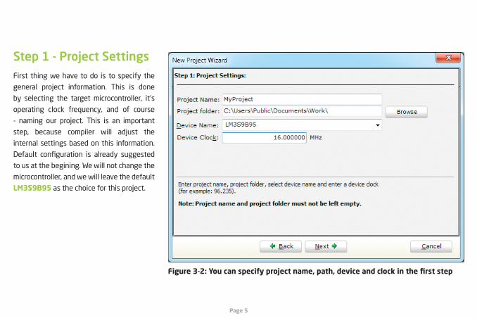
First thing we have to do is to specify the
general project information. This is done
by selecting the target microcontroller, it’s
operating clock frequency, and of course
- naming our project. This is an important
step, because compiler will adjust the
internal settings based on this information.
Default configuration is already suggested
to us at the begining. We will not change the
microcontroller, and we will leave the default
LM3S9B95 as the choice for this project.
Step 1 - Project Settings
Figure 3-2: You can specify project name, path, device and clock in the first step

Page 6 Page 7
If you do not want to use the suggested path
for storing your new project, you can change the destination folder. In order to do that,
follow a simple procedure:
Step 1 - Project Settings
Figure 3-3: Change the destination folder using Browse For Folder dialog
01
01
02
03 03
02
Click the Browse button of the Project
Settings window to open the Browse for Folder dialog.
Select the desired folder to be the
destination path for storing your new
project files.
Click the OK button to confirm your
selection and apply the new path.

Page 6 Page 7
Once we have selected the destination
project folder, let’s do the rest of the project
settings:
Step 1 - Project Settings
Figure 3-4: Enter project name and change device clock speed if necessary
01
02
03
03
01
02
Enter the name of your project. Since
we are going to blink some LEDs,
it’s appropriate to call the project
“LedBlinking”
For this demonstration, we will use
the default 16MHz clock. Clock speed
depends on your target hardware, and
whether you are using PLL or not. But
however you configure your hardware,
make sure to specify the exact clock
(Fosc) that the microcontroller is
operating at.
Click the OK button to proceed.

Page 8 Page 9
This step allows you to include additional files
that you need in your project: some headers
or source files that you already wrote, and
that you might need in further development.
Since we are building a simple application, we
won’t be adding any files at this moment.
Step 2 - Add files
01
Figure 3-5: Add existing headers, sources or other files if necessary
Click Next.01

Page 8 Page 9
Following step allows you to quickly set
whether you want to include all libraries in
your project, or not. Even if all libraries are
included, they will not consume any memory
unless they are explicitely used from within
your code. The main advantage of including
all libraries is that you will have over 500 functions available for use in your code
right away, and visible from Code Assistant
[CTRL+Space]. We will leave this in default
configuration:
Step 3 - Include Libraries
02
01
Figure 3-6: Include all libraries in the project, which is a default configuration.
01
02
Make sure to leave “Include All” selected.
Click Next.

Page 10 Page 11
After all configuration is done, final step
allows you to do just a bit more.
Step 4 - Finishing
Figure 3-7: Choose whether to open Edit Project window after dialog closes.
02
0101 There is a check-box called “Open Edit Project window to set Configuration bits” at the final step. Edit Project is a
specialized window which allows you to
do all the necessary oscillator and PLL
settings. We made sure that everything
is described in plain English, so you
will be able to do the settings without
having to open the datasheet. Anyway,
since we are only building a simple
application, we will leave it at default
configuration (internal 16MHz oscillator
with PLL disabled). Therefore, leave the checkbox unchecked.
Click Finish.02
Page 10 Page 11
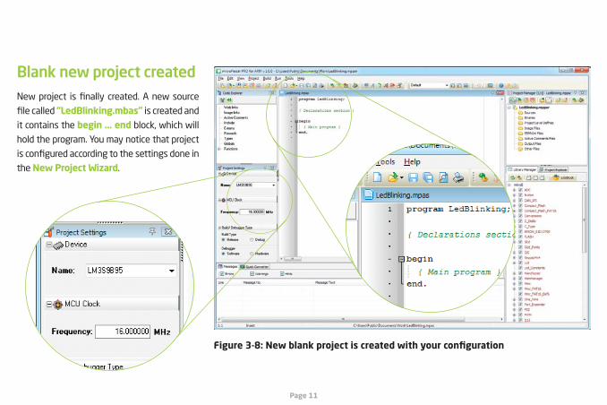
New project is finally created. A new source
file called “LedBlinking.mbas” is created and
it contains the begin ... end block, which will
hold the program. You may notice that project
is configured according to the settings done in
the New Project Wizard.
Blank new project created
Figure 3-8: New blank project is created with your configuration
Page 12 Page 13
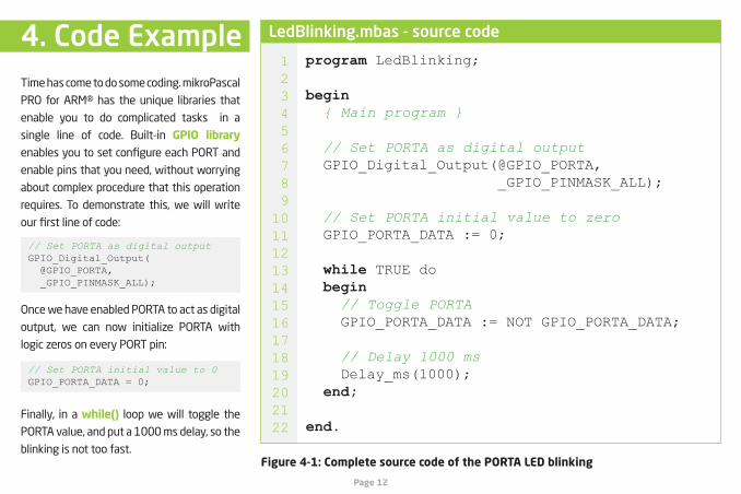
Time has come to do some coding. mikroPascal
PRO for ARM® has the unique libraries that
enable you to do complicated tasks in a
single line of code. Built-in GPIO library
enables you to set configure each PORT and
enable pins that you need, without worrying
about complex procedure that this operation
requires. To demonstrate this, we will write
our first line of code:
Once we have enabled PORTA to act as digital
output, we can now initialize PORTA with
logic zeros on every PORT pin:
Finally, in a while() loop we will toggle the
PORTA value, and put a 1000 ms delay, so the
blinking is not too fast.
program LedBlinking;
begin { Main program }
// Set PORTA as digital output GPIO_Digital_Output(@GPIO_PORTA, _GPIO_PINMASK_ALL);
// Set PORTA initial value to zero GPIO_PORTA_DATA := 0;
while TRUE do begin // Toggle PORTA GPIO_PORTA_DATA := NOT GPIO_PORTA_DATA;
// Delay 1000 ms Delay_ms(1000); end;
end.
// Set PORTA as digital outputGPIO_Digital_Output( @GPIO_PORTA, _GPIO_PINMASK_ALL);
// Set PORTA initial value to 0GPIO_PORTA_DATA = 0;
12345678910111213141516171819202122
LedBlinking.mbas - source code4. Code Example
Figure 4-1: Complete source code of the PORTA LED blinking

Page 12 Page 13
Figure 4-2: This is how the code looks written in compiler code editor window
Page 14 Page 15
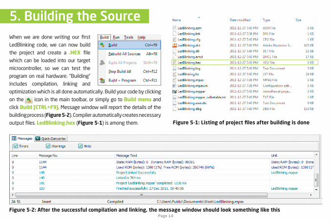
When we are done writing our first
LedBlinking code, we can now build
the project and create a .HEX file
which can be loaded into our target
microcontroller, so we can test the
program on real hardware. “Building”
includes compilation, linking and
optimization which is all done automatically. Build your code by clicking
on the icon in the main toolbar, or simply go to Build menu and
click Build [CTRL+F9]. Message window will report the details of the
building process (Figure 5-2). Compiler automatically creates necessary
output files. LedBlinking.hex (Figure 5-1) is among them.
5. Building the Source
Figure 5-2: After the successful compilation and linking, the message window should look something like this
Figure 5-1: Listing of project files after building is done
Page 14 Page 15
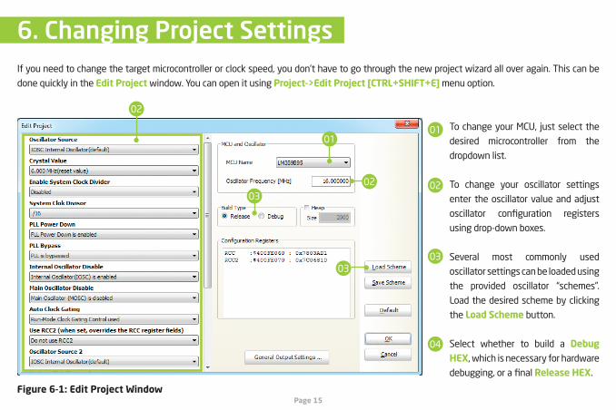
If you need to change the target microcontroller or clock speed, you don’t have to go through the new project wizard all over again. This can be
done quickly in the Edit Project window. You can open it using Project->Edit Project [CTRL+SHIFT+E] menu option.
6. Changing Project Settings
Figure 6-1: Edit Project Window
01
02
02
03
01
02
03
04
To change your MCU, just select the
desired microcontroller from the
dropdown list.
To change your oscillator settings
enter the oscillator value and adjust
oscillator configuration registers
using drop-down boxes.
Several most commonly used
oscillator settings can be loaded using
the provided oscillator “schemes”.
Load the desired scheme by clicking
the Load Scheme button.
Select whether to build a Debug HEX, which is necessary for hardware
debugging, or a final Release HEX.
03

If you want to learn more about our products, please
visit our website at www.mikroe.com. If you are
experiencing some problems with any of our products or
just need additional information, please place your ticket
at www.mikroe.com/esupport If you have any questions,
comments or business proposals, do not hesitate to
contact us at [email protected]
Designed by
MikroElektronika,
December 2011.