copyright by david charles sing 2013
TRANSCRIPT
Copyright
by
David Charles Sing
2013
The Thesis Committee for David Charles Sing
Certifies that this is the approved version of the following thesis:
Direct Measurement of Vanadium Cross-over in an Operating Redox
Flow Battery
APPROVED BY
SUPERVISING COMMITTEE:
Arumugam Manthiram
Jeremy P. Meyers
Supervisor:
Co-Supervisor:

Direct Measurement of Vanadium Cross-over in an Operating Redox
Flow Battery
by
David Charles Sing, B.S.; M.S.; Ph.D.
Thesis
Presented to the Faculty of the Graduate School of
The University of Texas at Austin
in Partial Fulfillment
of the Requirements
for the Degree of
Master of Science in Engineering
The University of Texas at Austin
May 2013
iv
Acknowledgements
I would like to thank first and foremost the love and support of my wife Meryl,
who likely did not expect to be supporting her graduate student husband at this stage of
our lives.
Next, I thank my advisor Dr. Jeremy Meyers for offering a research assistant
position to a middle-aged engineer who many would have thought was just suffering
through a mid-life career crisis. Thanks also to the other members of the Meyers research
group, especially my friend and colleague Philip Michael, who helped me tremendously
getting our lab set up and getting our first battery experiments going. It was fun working
with Philip while we both plunged ahead into a brand new field for both of us.
Finally I would like to thank the faculty and staff of the Materials Science and
Engineering program. I was fortunate to be able to learn from world class professors such
as Dr. John Goodenough, Dr. Allan Bard, Dr. Arumugam Manthiram, and the rest of the
faculty members of the MS&E program. Thank you also to the talented staff of the
Mechanical Engineering Department machine shop, lead by Mr. Scott Allen, especially
for putting up with last minute modifications and additions to my job submissions.
Finally, I would like to acknowledge the financial supporters of my research, including
United Technologies Research Center and the US Department of Energy. This work was
supported by the US DOE ARPA-E program under grant # DE-AR00000149.
v
Abstract
Direct Measurement of Vanadium Cross-over in an Operating Redox
Flow Battery
David Charles Sing, M.S.E.
The University of Texas at Austin, 2013
Supervisor: Arumugam Manthiram
Co-Supervisor: Jeremy P. Meyers
A redox flow battery (RFB) is an electrochemical energy storage device in which
the storage medium is in the form of liquid electrolyte, which is stored in external
reservoirs separate from the cell stack. The storage capacity of such systems is limited by
the size of the external tanks, making the RFB an ideal technology for grid level energy
storage. The vanadium redox flow battery (VRB) is a particularly attractive variant of the
RFB, due to its use of a single transition-metal element in both the positive and negative
electrolytes. However, the performance of the VRB is affected by the cross-over of
electrolytes through the ion-exchange membrane which separates the positive and
negative electrolytes. Cross-over causes degradation of energy storage efficiency and
long term capacity loss. Previous studies of ion cross-over have focused primarily on the
measurement of ion diffusion across ion exchange membranes in the absence of electrical
current. In this work a novel VRB cell is described in which ion cross-over can be
measured directly in the presence and absence of electrical current. Measurements are

vi
made of cross-over using this cell with three different types of ion exchange membrane in
both charge and discharge modes. The results reported in this work show that the rate of
ion cross-over can be greatly enhanced or suppressed depending upon the magnitude of
the current flow and its direction relative to the ion concentration gradient.

vii
Table of Contents
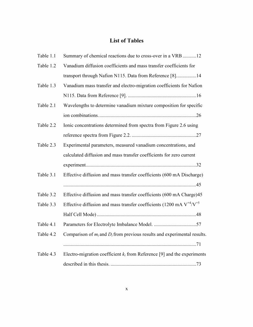
List of Tables ...........................................................................................................x
List of Figures ....................................................................................................... xii
Chapter 1: Introduction to Vanadium Redox Flow Batteries .................................1
1.1 Flow batteries for Grid-Level Energy Storage......................................1
1.2 Vanadium redox flow batteries ..............................................................5
1.3 Experimental Apparatus.........................................................................7
Experimental VRB Cell .........................................................................7
Electrolyte Preparation...........................................................................9
Ion Exchange Membrane .....................................................................10
1.4 Brief Review of Previous Ion Cross-over Measurements ....................13
Dialysis Cell Experiments....................................................................13
Redox Flow Battery Experiments ........................................................14
1.5 Triple membrane cell ...........................................................................17
Chapter 2: Optical Measurement of Vanadium Ion Concentrations and Transport
Coefficients ...................................................................................................19
2.1 Beer’s Law for Mixtures of Absorbing Species ..................................19
2.2 Spectroscopic Analysis of Vanadium Ion Mixtures ............................21
2.3 Analysis of VRB Electrolyte Samples .................................................24
2.4 Calculation of Membrane Transport Coefficients ...............................28
2.5 Summary of Optical Measurement of Vanadium Ion Concentrations and
Transport Coefficients .........................................................................32
Chapter 3: Cross-over Measurements using the Triple Membrane VRB Cell ......34
3.1 Vanadium Redox Flow Battery Operation ..........................................34
3.2 Triple Membrane (XO) Cell ................................................................35
3.4 Full Cell Mode XO Experiments .........................................................38
3.5 Electric Field Effect on Transport Coefficients ...................................43
3.6 Half Cell Mode XO Experiments ........................................................46

viii
Chapter 4: The Effects of Current Density on Vanadium Cross-over ...................50
4.1 Cross-Over experiments with N212 Membranes 0.7 M Solutions ......50
Half Cell Mode Experiments with V+4
/V+5
..........................................51
Half Cell and Full Cell Experiments with V+2
/V+3
..............................52
Combined V+2
/V+3
and V+4
/V+5
Mass Transfer Coefficients ..............53
4.2 Predicting Cell Imbalance from Mass Transfer Coefficients ..............55
Prediction of Cell Imbalance from V+2
/V+3
and V+4
/V+5
mass transfer
coefficients ..................................................................................56
Experimental Measurement of Cell Imbalance over two charge/discharge
cycles...........................................................................................58
4.3 Cross-Over experiments with 1.5 M Solutions ....................................62
Membrane comparison experiments ....................................................62
N212 Membrane Experiments with 1.5 M V solutions ..............63
N117 Membrane Experiments with 1.5 M V solutions ..............64
FX-7050 Membrane Experiments with 1.5 M V solutions .........65
Direct Comparison of N212, N117, and FX-70450 Combined V+4
/
V+5
Transport Coefficients .................................................66
4.4 Evidence of oxidation of V+4
to V+5
in XO cell ..................................67
Cross-over Experiments with Vanadium solutions in the +XO
reservoir .............................................................................68
4.5 Comparison of Experimental results with Previous measurements .....70
4.6 Conclusions for Current density scaling study experiments ................73
Chapter 5: Convective Flow Effects on Cross-over ..............................................76
5.1 Convective flow effects on mass transport ..........................................76
5.2 Convective flow/ Variable Sulfate concentration cross-over experiments
..............................................................................................................77
Experiment Configuration ...................................................................77
Data Analysis using a Full Factorial Model ........................................79
5.3 Comparison of Variable Sulfate concentration model with results from
current scaling experiments .................................................................82
5.4 Conclusions for Convective flow effects on cross-over ......................84

ix
Chapter 6: Conclusions and Recommendations for Future Work .........................85
6.1 Conclusions ..........................................................................................85
Spectroscopic measurement of Vanadium electrolyte mixtures ..........85
Triple Membrane Cell ..........................................................................85
Scaling of Cross-over with Current Density ........................................86
Prediction of Electrolyte imbalance .....................................................86
Demonstration of convective flow effects ...........................................87
Oxidation of V+4
to V+5
during cross-over measurements ...................88
6.2 Recommendations for future work ......................................................89
Improvements in the VRB cell designs ...............................................89
Membrane selection within the XO cell ..............................................89
Half Cell Mode Experiment Improvements .........................................90
Additional Experiments on Convective Flow Effects .........................91
Experiments with Advanced VRB Cell Designs .................................91
Investigation of other Variables affecting Cross-over .........................92
6.3 Closing Remarks ..................................................................................93
Appendix: Compilation of Experimental Run Data...............................................94
Chapter 4 Experiments ..................................................................................94
References ..............................................................................................................97
x
List of Tables
Table 1.1 Summary of chemical reactions due to cross-over in a VRB ...........12
Table 1.2 Vanadium diffusion coefficients and mass transfer coefficients for
transport through Nafion N115. Data from Reference [8]. ...............14
Table 1.3 Vanadium mass transfer and electro-migration coefficients for Nafion
N115. Data from Reference [9]. .......................................................16
Table 2.1 Wavelengths to determine vanadium mixture composition for specific
ion combinations. ..............................................................................26
Table 2.2 Ionic concentrations determined from spectra from Figure 2.6 using
reference spectra from Figure 2.2. ....................................................27
Table 2.3 Experimental parameters, measured vanadium concentrations, and
calculated diffusion and mass transfer coefficients for zero current
experiment.........................................................................................32
Table 3.1 Effective diffusion and mass transfer coefficients (600 mA Discharge)
...........................................................................................................45
Table 3.2 Effective diffusion and mass transfer coefficients (600 mA Charge)45
Table 3.3 Effective diffusion and mass transfer coefficients (1200 mA V+4
/V+5
Half Cell Mode) ................................................................................48
Table 4.1 Parameters for Electrolyte Imbalance Model. ..................................57
Table 4.2 Comparison of mi and Di from previous results and experimental results.
...........................................................................................................71
Table 4.3 Electro-migration coefficient ki from Reference [9] and the experiments
described in this thesis. .....................................................................73

xi
Table 5.1 Fluid volume increases and water flux for runs with 2.5 M sulfate
concentration difference. ...................................................................79
Table 5.2 Experimental Conditions and Results for variable sulfate experiments.
...........................................................................................................81
Table A1 Low Concentration (0.7 M) V+2/
V+3
and V+4/
V+5
N212 Cross-over Data
(Figures 4.1, 4.2, 4.3, 4.4). ................................................................94
Table A2 High Concentration (1.5 M) V+4/
V+5
with N212, N117, FX-7050
membranes (Figures 4.9. 4.10, 4.11, 4.12). ......................................95
Table A3 V+4/
V+5
Electrolyte in +XO (Figure 4.15).........................................96
Table A4 Variable Sulfate (Figure 5.2). ...........................................................96

xii
List of Figures
Figure 1.1 Energy storage used to buffer and load shift output from a solar
generation facility. Figure adapted from reference [20]. ....................2
Figure 1.2 Flow Battery Schematic Diagram. ......................................................3
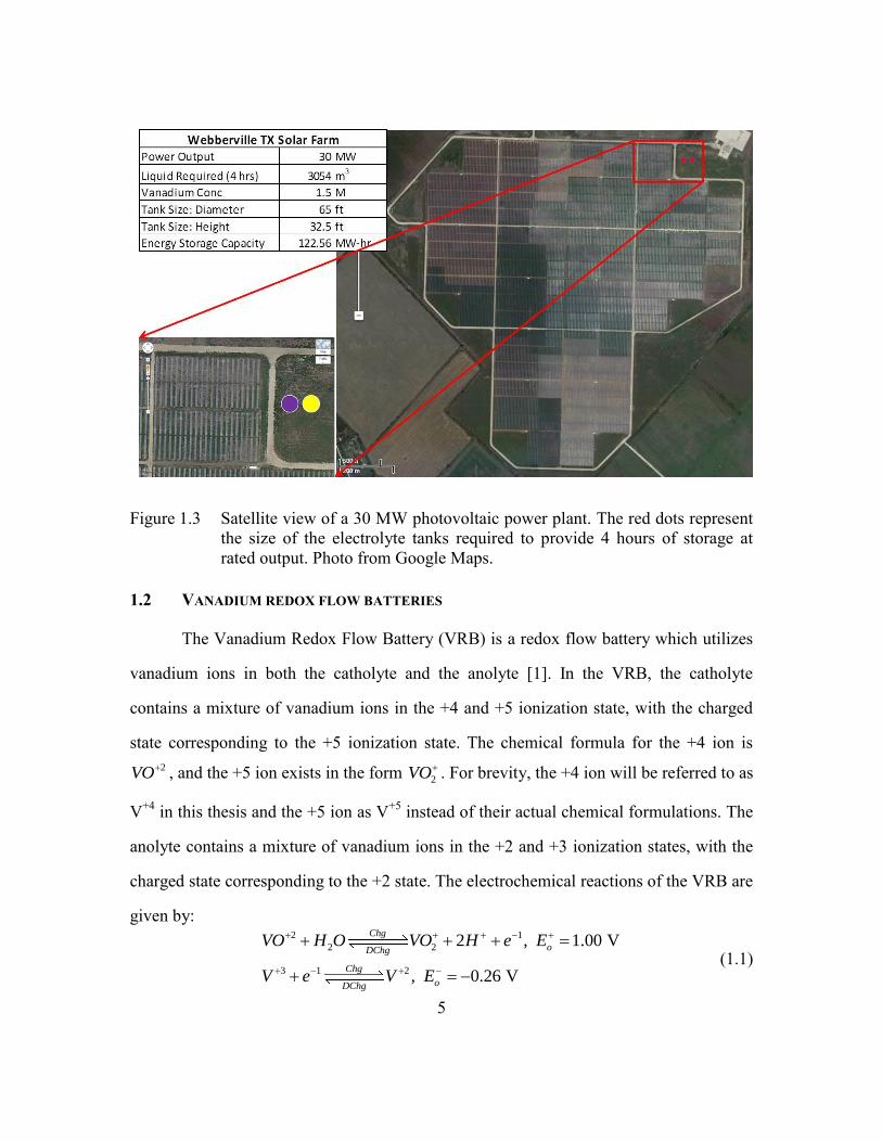
Figure 1.3 Satellite view of a 30 MW photovoltaic power plant. The red dots
represent the size of the electrolyte tanks required to provide 4 hours of
storage at rated output. Photo from Google Maps. .............................5
Figure 1.4 Experimental VRB Cell (a) attached to experimental apparatus (b)
Exploded view. ...................................................................................8
Figure 1.5 VRB Cell and supporting hardware. ...................................................9
Figure 1.6 Schematic of Dialysis Cell Experiment. Copied from Reference [7].13
Figure 1.7 Schematic of Fe/V Flow Battery cells to measure V transport across ion
exchange membranes with electrical current flowing. Copied from Ref.
[9]. .....................................................................................................15
Figure 1.8 Triple Membrane Cell Schematic Diagram. .....................................18
Figure 2.1 Vanadium 0.1 M solutions, ionization states +2 through +5. Photograph
by the author. ....................................................................................21
Figure 2.2 Absorption spectra of 0.1 M samples of vanadium cations (a) V+4
and
V+5
(b) V+2
and V+3
. ..........................................................................21
Figure 2.3 Absorption spectra of negative VRB electrolytes from 0% to 100%
SOC, 1 M total V concentration. Figure from Tang et.al. [12].........22
Figure 2.4 Absorption spectra of positive VRB electrolyte from 100% SOC (100%
V+5
) to 0% SOC (100% V+4
). 0.5 M total V concentration. Figure from
Tang et. al. [12]. ................................................................................23

xiii
Figure 2.5 (a) Absorption spectra V+4
/V+5
mixtures with total V concentration 0.07
M. Nominal V+4
content 20% through 80%. (b) Spectra of linear
combination of V+4
and V+5
spectra fit to spectra shown in (a). .......24
Figure 2.6 Sample mixture spectra and fit to reference spectra (labeled “Sum V4
V5” etc) for (a) V+5
/V+4
(b) V+4/
V+3
and (c) V+3
/V+2
mixtures. ........26
Figure 2.7 Experimental setup for a vanadium membrane transport experiment.28
Figure 2.8 (a) V+ and V- Absorption Spectra (b) +XO and -XO Absorption
Spectra, XO cell with no current flow. .............................................31
Figure 3.1 VRB Cell for initial experiments. N117 Membrane, no current defining
aperture. ............................................................................................34
Figure 3.2 (a) Current vs Voltage (b) Power Density vs Current Density for VRB
with N117 and N212 membranes .....................................................35
Figure 3.3 Exploded view of Triple membrane (XO) Cell ................................36
Figure 3.4 (a) XO Cell showing electrolyte inputs and outputs (b) internal view
showing a white ion exchange membrane separating the V- chamber
from the –XO chamber and the 2 cm2 Teflon current defining aperture.
...........................................................................................................37
Figure 3.5 XO running as a VRB showing current flow during charge and
discharge. ..........................................................................................38
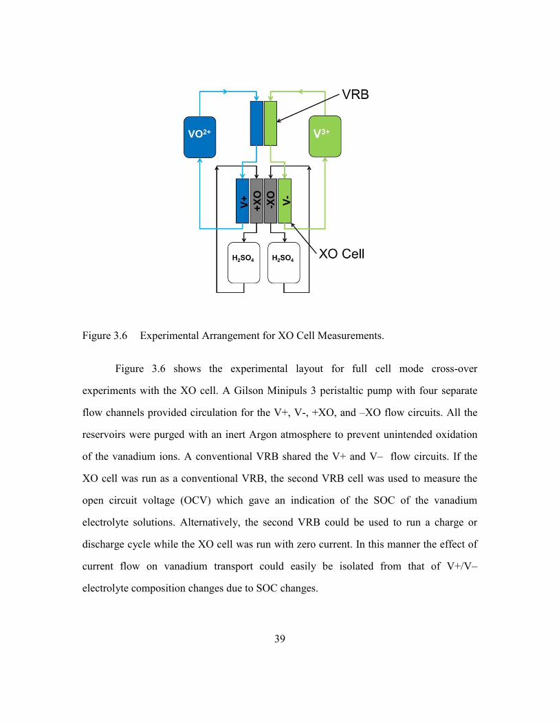
Figure 3.6 Experimental Arrangement for XO Cell Measurements. .................39
Figure 3.7 Full Cell Mode I-V curve for XO cell operating as a VRB. .............40
Figure 3.8 Absorption spectrographs for XO cell electrolytes collected during a full
cell mode 600 mA experiment. (a) Initial V+ (b) Final V+ (c) Initial V-
(d) Final V- (e) +XO (f) -XO. ...........................................................41
Figure 3.9 Effect of current flow direction on +XO and -XO spectra. ..............42

xiv
Figure 3.10 Effective mass transfer coefficients for (a) V+4
and V+5
and (b) V+2
and
V+3
versus cell operation mode. ........................................................46
Figure 3.11 (a) Experimental arrangement for V+4
/V+5
half cell mode experiments
(b) V+ absorption spectra (c) V– spectra (d) +XO spectrum (e) –XO
spectrum. ...........................................................................................47
Figure 3.12 Effective mass transfer coefficient vs. current density, XO cell
experiments. ......................................................................................48
Figure 4.1 V+4
and V+5
m* vs current density, N212 Membrane 0.7 M V
concentration, Half cell mode. ..........................................................52
Figure 4.2 V+2
and V+3
m* vs current density, N212 Membrane 0.7 M V
concentration. Half cell (‘V2V3’) and full cell (‘V2V3V4V5’) mode
experiments. ......................................................................................53
Figure 4.3 Combined V+2
/V+3
mass transport coefficient vs current density.....54
Figure 4.4. Combined V+4
/V+5
mass transport coefficient vs current density.....55
Figure 4.5 Development of steady state imbalance in vanadium concentration due
to differences in transport rates. Parameters as listed in Table 4.1. ..58
Figure 4.6 Vanadium concentrations in the (a) V+ and (b) V- electrolytes during the
first discharge/charge cycle of a two cycle cross-over experiment. .59
Figure 4.7 Spectra of samples from +XO in (a) (c) (e) and (g) and from –XO in (b)
(d) (f) and (g) measured after each step of a two cycle discharge/charge
cross-over experiment. ......................................................................60
Figure 4.8 (a) Cumulative concentrations of vanadium collected in +XO and –XO
reservoirs during two cycle cross-over experiment. (b) Mass transfer
coefficients for V+ to +XO and V- to –XO averaged over two
discharge/charge cycles. ...................................................................61

xv
Figure 4.9 V+4
and V+5
m* vs current density, N212 Membrane 1.5 M V
concentration, Half cell mode. ..........................................................63
Figure 4.10 V+4
and V+5
m* vs current density, N117 Membrane, 1.5 M V
concentration. Half cell mode. ..........................................................64
Figure 4.11 V+4
and V+5
m* vs current density, FX-7050 Membrane, 1.5 M V
concentration. Half cell mode ..........................................................65
Figure 4.12 (a) Combined V+4
and V+5
transport coefficient vs current density for
N212, N117, and FX-7050 Membranes -1000 to 1000 mA/cm2 (b) -1000
to 0 mA/cm2 x-axis. ..........................................................................66
Figure 4.13 (a) XO electrode without leakage path cannot support V+4
oxidation. (b)
Leakage path through membrane allows V+4
oxidation reaction to occur.
...........................................................................................................67
Figure 4.14 Experimental configuration with V electrolyte (V+4
this illustration) in
+XO reservoir and sulfuric acid in -XO reservoir. Experiments
conducted with V+5
and V+4
in +XO. .................................................68
Figure 4.15 V+4
and V+5
mass transfer coefficients obtained using the cell
configuration of Figure 4.14. 0.7 M V+4
or 0.8 M V+5
solutions in +XO.
...........................................................................................................70
Figure 5.1 Experimental configuration for convective flow experiments. .........77
Figure 5.2 Calculated Mass Transport Coefficients for the variable sulfate
experiments. ......................................................................................79
Figure 5.3 Comparison of Full Factorial and Linear Model fits to measured mass
transport coefficient data...................................................................82

xvi
Figure 5.4 Comparison of V+4
m*
from different experiments (described in Chapter
4) with results from full factorial model of variable sulfate experiment.
...........................................................................................................83

1
Chapter 1: Introduction to Vanadium Redox Flow Batteries
In this chapter, the motivation for the research is briefly discussed, followed by an
introduction to redox flow batteries (RFB) and the all-vanadium redox flow battery in
particular. The experimental apparatus is described and a brief review of relevant
previous experimental results from the literature is discussed. In subsequent chapters of
this thesis the use of absorption spectroscopy for determination of the composition of
vanadium ion mixtures will be discussed, as well as the methods for calculating cross-
over rates from the spectroscopic data. A large chapter is devoted to a discussion of
scaling studies of cross-over variation with electric current density, followed by a shorter
chapter discussing an experimental study of the effects of convective flows on cross-over.
Finally a summary of the results and recommendations for future work is presented in the
final chapter.
1.1 FLOW BATTERIES FOR GRID-LEVEL ENERGY STORAGE
Grid-level energy storage is essential for widespread integration of renewable
energy sources such as wind and solar into the national energy grid. Energy storage
capability allows rapid fluctuations in output due to factors such as cloud cover to be
buffered, and over longer time periods the storage of energy generated during peak
production times for use later during periods of peak demand. Figure 1.1 illustrates how
storage can firm up the capacity of a solar power generation facility.

2
Figure 1.1 Energy storage used to buffer and load shift output from a solar generation
facility. Figure adapted from reference [20].
Among the many proposed systems for grid level energy storage is the redox flow
battery (RFB). The RFB is an electrochemical energy storage device in which the storage
medium is in the form of liquid electrolytes containing ionic species which are either
oxidized or reduced to store and release electrical energy. A schematic diagram of a
redox flow battery is shown in Figure 1.2. External tanks store the two electrolyte
species, the positive electrolyte (catholyte), which is reduced during electrical discharge,
and the negative electrolyte (anolyte), which is oxidized during discharge. Many flow
battery systems use aqueous electrolytes with a strong acid as supporting electrolyte to
provide a ready source of hydrogen ions needed as charge carriers in the electrolyte and
ionomer. External pumps circulate the electrolytes through the cell stack, the flow rate is
such that in most cases the only a small percentage of the electrolyte is reacted in a single
pass. Within the cell stack porous conducting electrodes are separated by an ion exchange
membrane which allows hydrogen ions to pass but keeps the electrolyte species from
mixing. The porous electrodes provide a large surface area for the heterogeneous
electrochemical reactions to occur. Current collectors in contact with the porous

3
electrodes conduct electrons generated by the electrochemical reactions to and from the
external circuit.
Figure 1.2 Flow Battery Schematic Diagram.
The most important feature of the flow battery is that the energy capacity of the
battery depends on the size of the external electrolyte reservoirs, and thus is completely
decoupled from the power rating of the system, which is proportional to the cross
sectional area of the flow battery cell stack. The decoupling of storage capacity from
power capacity makes flow batteries good candidates for large-scale energy storage
applications.
The size of the electrolyte reservoirs required for a given energy storage
application is easily estimated. The strength of typical anolytes and catholytes used in

4
most RFB systems is 1 to 2 M, and the energy stored per electron is on the order of 1 eV.
Therefore, assuming an electrolyte strength of 1.5 M, each liter of electrolyte can store
the following amount of energy:
23 19 (mole/L) (electrons/mole) (eV/electron) (J/eV)
(J/L)
(W-hr/L)
1.5 6.02 10 1 1.6 10
=144480
40.13
(1.1)
Storage of the output of a 30 MW solar power plant for 4 hours would require 120 MW-
hr of storage capacity, and with a specific capacity of 40.13 W-hr/liter, the volume of
electrolyte of each type (anolyte and catholyte) would be 62.99 10 liters. A tank to store
that amount of liquid is approximately 65 feet in diameter and 32.5 feet tall, which is
comparable to the size of tanks found in a typical petroleum tank farm. Compared to the
scale of a typical photovoltaic power plant, tanks of this size are very reasonably sized.
Figure 1.3 shows a satellite view of the City of Austin 30 MW photovoltaic power plant
in Webberville, TX, with two red dots representing 65 foot diameter electrolyte storage
tanks. Compared to the scale of the photovoltaic plant the tanks required for energy
storage are quite small. In actual practice a modular set of tanks and RFB stacks would be
used, but this example shows that large scale storage facilities can be accommodated by
current renewable energy resources.
5
Figure 1.3 Satellite view of a 30 MW photovoltaic power plant. The red dots represent
the size of the electrolyte tanks required to provide 4 hours of storage at
rated output. Photo from Google Maps.
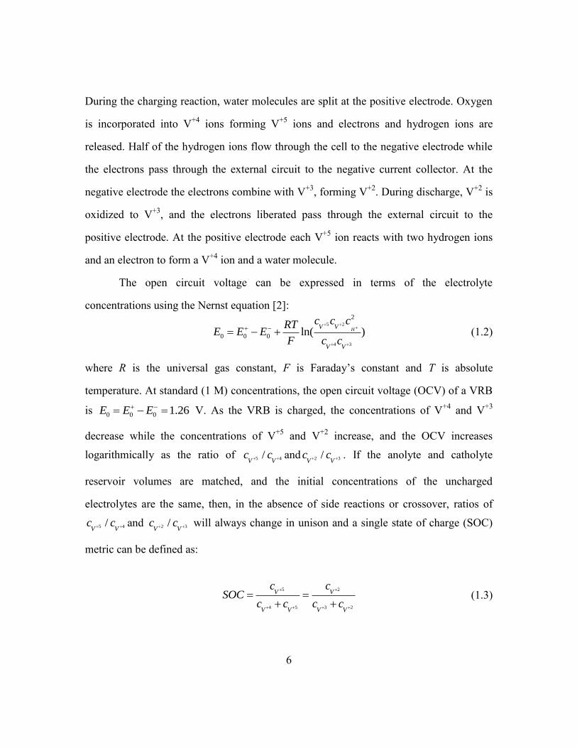
1.2 VANADIUM REDOX FLOW BATTERIES
The Vanadium Redox Flow Battery (VRB) is a redox flow battery which utilizes
vanadium ions in both the catholyte and the anolyte [1]. In the VRB, the catholyte
contains a mixture of vanadium ions in the +4 and +5 ionization state, with the charged
state corresponding to the +5 ionization state. The chemical formula for the +4 ion is
2VO , and the +5 ion exists in the form 2VO . For brevity, the +4 ion will be referred to as
V+4
in this thesis and the +5 ion as V+5
instead of their actual chemical formulations. The
anolyte contains a mixture of vanadium ions in the +2 and +3 ionization states, with the
charged state corresponding to the +2 state. The electrochemical reactions of the VRB are
given by:
2 1
2 2
3 1 2
2 , 1.00 V
, 0.26 V
Chg
oDChg
Chg
oDChg
VO H O VO H e E
V e V E
(1.1)
6
During the charging reaction, water molecules are split at the positive electrode. Oxygen
is incorporated into V+4
ions forming V+5
ions and electrons and hydrogen ions are
released. Half of the hydrogen ions flow through the cell to the negative electrode while
the electrons pass through the external circuit to the negative current collector. At the
negative electrode the electrons combine with V+3
, forming V+2
. During discharge, V+2
is
oxidized to V+3
, and the electrons liberated pass through the external circuit to the
positive electrode. At the positive electrode each V+5
ion reacts with two hydrogen ions
and an electron to form a V+4
ion and a water molecule.
The open circuit voltage can be expressed in terms of the electrolyte
concentrations using the Nernst equation [2]:
5 2
4 3
2
0 0 0 ln( )HV V
V V
c c cRTE E E
F c c
(1.2)
where R is the universal gas constant, F is Faraday’s constant and T is absolute
temperature. At standard (1 M) concentrations, the open circuit voltage (OCV) of a VRB
is 0 0 0 1.26E E E V. As the VRB is charged, the concentrations of V+4
and V+3
decrease while the concentrations of V+5
and V+2
increase, and the OCV increases
logarithmically as the ratio of 5 4/V V
c c and 2 3/V V
c c . If the anolyte and catholyte
reservoir volumes are matched, and the initial concentrations of the uncharged
electrolytes are the same, then, in the absence of side reactions or crossover, ratios of
5 4/V V
c c and 2 3/V V
c c will always change in unison and a single state of charge (SOC)
metric can be defined as:
5 2
4 5 3 2
V V
V V V V
c cSOC
c c c c
(1.3)
7
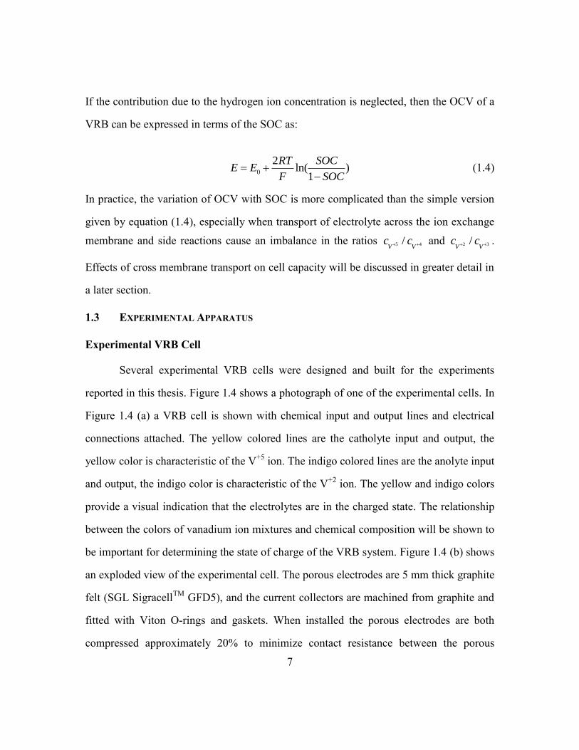
If the contribution due to the hydrogen ion concentration is neglected, then the OCV of a
VRB can be expressed in terms of the SOC as:
0
2ln( )
1
RT SOCE E
F SOC
(1.4)
In practice, the variation of OCV with SOC is more complicated than the simple version
given by equation (1.4), especially when transport of electrolyte across the ion exchange
membrane and side reactions cause an imbalance in the ratios 5 4/V V
c c and 2 3/V V
c c .
Effects of cross membrane transport on cell capacity will be discussed in greater detail in
a later section.
1.3 EXPERIMENTAL APPARATUS
Experimental VRB Cell
Several experimental VRB cells were designed and built for the experiments
reported in this thesis. Figure 1.4 shows a photograph of one of the experimental cells. In
Figure 1.4 (a) a VRB cell is shown with chemical input and output lines and electrical
connections attached. The yellow colored lines are the catholyte input and output, the
yellow color is characteristic of the V+5
ion. The indigo colored lines are the anolyte input
and output, the indigo color is characteristic of the V+2
ion. The yellow and indigo colors
provide a visual indication that the electrolytes are in the charged state. The relationship
between the colors of vanadium ion mixtures and chemical composition will be shown to
be important for determining the state of charge of the VRB system. Figure 1.4 (b) shows
an exploded view of the experimental cell. The porous electrodes are 5 mm thick graphite
felt (SGL SigracellTM
GFD5), and the current collectors are machined from graphite and
fitted with Viton O-rings and gaskets. When installed the porous electrodes are both
compressed approximately 20% to minimize contact resistance between the porous

8
electrodes and the current collectors. The porous electrode and current collectors fit into
PVC frame pieces with manifolds for electrolyte flow and are fitted with acid resistant
PVDF tube fittings. An ion exchange membrane is sandwiched between the PVC frame
pieces and is sealed with 1.5 mm Viton gaskets. A 75 micron thick Teflon gasket with a 4
cm by 4 cm opening defines the cross sectional area for current flow through the cell.
Figure 1.4 Experimental VRB Cell (a) attached to experimental apparatus (b) Exploded
view.
Figure 1.5 shows the balance of the equipment used in the experiments. A Gilson
MinipulsTM
3 peristaltic pump is used to pump the electrolytes through the VRB Cell.
Pyrex flasks with rubber stoppers and glass tubing are used to form the electrolyte
reservoirs. Both electrolyte reservoirs can be purged with Argon gas to prevent oxidation
from atmospheric oxygen, in practice only the anolyte reservoir requires purging to
prevent the V+2
ionic species from being oxidized. Acid resistant plastic and Viton tubing
are used throughout. Figure 1.5 also shows two additional reservoirs (labeled “Cross-over
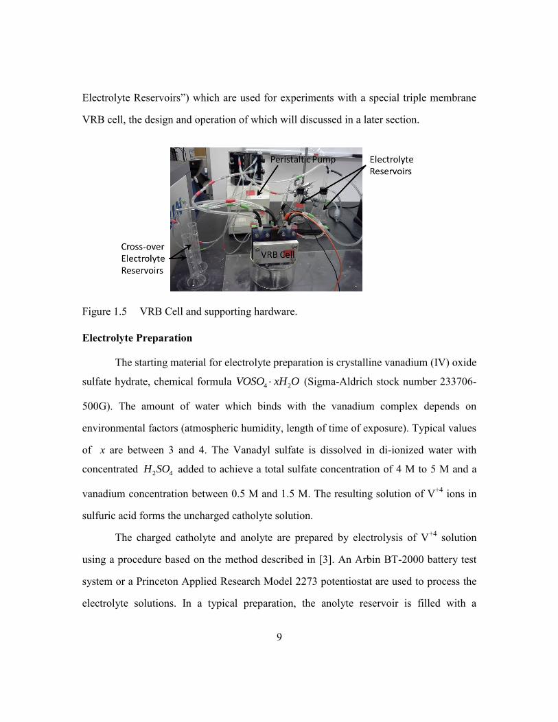
9
Electrolyte Reservoirs”) which are used for experiments with a special triple membrane
VRB cell, the design and operation of which will discussed in a later section.
Figure 1.5 VRB Cell and supporting hardware.
Electrolyte Preparation
The starting material for electrolyte preparation is crystalline vanadium (IV) oxide
sulfate hydrate, chemical formula 4 2VOSO xH O (Sigma-Aldrich stock number 233706-
500G). The amount of water which binds with the vanadium complex depends on
environmental factors (atmospheric humidity, length of time of exposure). Typical values
of x are between 3 and 4. The Vanadyl sulfate is dissolved in di-ionized water with
concentrated 2 4H SO added to achieve a total sulfate concentration of 4 M to 5 M and a
vanadium concentration between 0.5 M and 1.5 M. The resulting solution of V+4
ions in
sulfuric acid forms the uncharged catholyte solution.
The charged catholyte and anolyte are prepared by electrolysis of V+4
solution
using a procedure based on the method described in [3]. An Arbin BT-2000 battery test
system or a Princeton Applied Research Model 2273 potentiostat are used to process the
electrolyte solutions. In a typical preparation, the anolyte reservoir is filled with a

10
quantity of V+4
solution while the catholyte reservoir is filled with twice that amount of
V+4
solution. The anolyte and catholyte solutions are pumped through a VRB cell, and a
constant charging current with a current density of 65 mA/cm2 is injected into the
positive electrode of the VRB cell. The applied electrical current drives the following
chemical reactions in the VRB:
2 1
2 2
2 1 3
2
3 1 2
Positive Electrode:
2
Negative Electrode:
2
VO H O VO H e
VO H e V H O
V e V
(1.5)
Since the volume of catholyte is twice that of the anolyte, a single oxidation reaction
occurs at the positive electrode while two successive reduction reactions occur at the
negative electrode. At the positive electrode V+4
is oxidized to the V+5
ionization state. At
the negative electrode, V+4
is reduced to V+3
, which is further reduced to V+2
after all the
V+4
in the anolyte is exhausted. The endpoint of the reaction is indicated by a sharp rise
in the applied voltage and a dramatic color change in the solutions, with the anolyte
assuming the indigo color characteristic of V+2
and the catholye becoming yellow which
is characteristic of V+5
.
Ion Exchange Membrane
One of the most important components of a VRB is the ion exchange membrane.
The ion exchange membrane has two competing roles: maintaining separation of the
electrolyte species while providing a high conductivity path for hydrogen ions to
complete the electrical circuit within the VRB. For a given material, a thick membrane
will offer increased resistance to mixing of the electrolyte species, but at the cost of
higher internal cell resistance. In general, materials which offer superior separation of

11
electrolytes have higher resistivity. Three different ion exchange membranes were used in
this thesis: Dupont NafionTM
117, Nafion 212, and FumatechTM
FX-7050.
The transport of the anolyte and catholyte across the ion exchange membrane is
called electrolyte cross-over. Electrolyte cross-over leads to loss of energy efficiency and
cell capacity. In a VRB, V+4
and V+5
ions from the catholyte which pass through the ion
exchange membrane will react with the V+2
and V+3
ions in the anolyte according to the
following reactions:
+4 2 +3
2 2 3
2
+5 2 +3
2 3 2
2 2
3 2
2
V into V /V :
2 2
V into V /V :
2
2
VO V H V H O
VO V H V VO H O
VO V VO
(1.6)
V+4
ions that cross-over into the anolyte can only react with V+2
ions, forming two V+3
ions for every V+4
ion. V+5
ions can react with either V+2
or V+3
ions. If there is sufficient
amount of V+2
present, a V+5
ion will react with V+2
to form a V+3
and V+4
ion. The V+4
ion formed will react with additional V+2
to form two more V+3
ions, which makes a total
of three V+3
ions for every V+5
ion which enters the anolyte. A similar set of reactions
occurs when V+2
and V+3
cross over into the catholyte:
+3 +4 +5
3 2
2
+2 +4 +5
2 2 3
2
2 3 2
2 2
V into V /V :
2
V into V /V :
2 2
2
V VO VO
V VO H V H O
V VO H V VO H O
(1.7)
V+3
ions which cross-over to the catholyte can only react with V+5
ions, forming two V+4
ions for every V+3
ion. V+2
ions can react with either V+4
or V+5
ions. If there is a
sufficient amount of V+5
present, a V+2
ion will react V+5
to form a V+3
and V+4
ion. The

12
V+3
ion will react with additional V+5
to form two more V+4
ions, which makes a total of
three V+4
ions formed for every V+2
ion which enters the catholyte. Table 1.1 summarizes
the reactants and products of cross-over ion reactions. It is apparent that cross-over ions
have the effect of discharging the cell, with V+2
and V+5
ions having twice the discharge
effect of V+3
and V+4
ions.
Table 1.1 Summary of chemical reactions due to cross-over in a VRB
In addition to causing self-discharge, cross-over can also lead to a permanent loss
of capacity in a flow battery system [4,5]. Capacity loss results when the net flux of ion
cross-over is non-zero over a charge and discharge cycle, leading to excess vanadium on
one side of the cell and a deficit on the other side. When this occurs, the cell is said to be
unbalanced, and the half cell with less vanadium will cycle over larger range of SOC with
each charge/discharge cycle, while the cell with more vanadium will cycle over a smaller
range of SOC. Unbalancing is a direct result of differences in the transport coefficients
of the various ionic species through the ion exchange membrane. Knehr et.al. showed
that small imbalances in transport, which over a single charge/discharge cycle result in
only a fraction of a percent loss in capacity, can over many (45) cycles result in a large
(17%) capacity loss [5]. Since VRB’s are designed to run many thousands of cycles,
capacity loss due to electrolyte imbalance is a serious problem from an operational
standpoint.
13
1.4 BRIEF REVIEW OF PREVIOUS ION CROSS-OVER MEASUREMENTS
Dialysis Cell Experiments
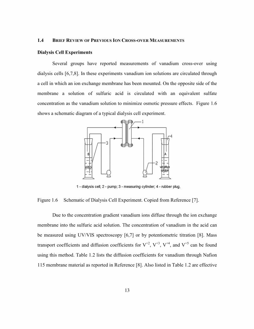
Several groups have reported measurements of vanadium cross-over using
dialysis cells [6,7,8]. In these experiments vanadium ion solutions are circulated through
a cell in which an ion exchange membrane has been mounted. On the opposite side of the
membrane a solution of sulfuric acid is circulated with an equivalent sulfate
concentration as the vanadium solution to minimize osmotic pressure effects. Figure 1.6
shows a schematic diagram of a typical dialysis cell experiment.
Figure 1.6 Schematic of Dialysis Cell Experiment. Copied from Reference [7].
Due to the concentration gradient vanadium ions diffuse through the ion exchange
membrane into the sulfuric acid solution. The concentration of vanadium in the acid can
be measured using UV/VIS spectroscopy [6,7] or by potentiometric titration [8]. Mass
transport coefficients and diffusion coefficients for V+2
, V+3
, V+4
, and V+5
can be found
using this method. Table 1.2 lists the diffusion coefficients for vanadium through Nafion
115 membrane material as reported in Reference [8]. Also listed in Table 1.2 are effective

14
mass transfer coefficients mi calculated by dividing the diffusion coefficients by the
membrane thickness.
Table 1.2 Vanadium diffusion coefficients and mass transfer coefficients for transport
through Nafion N115. Data from Reference [8].
However, in an operating VRB, an electrical current primarily carried by the H+
ions is also present, and with it an electro-osmotic flow of water. vanadium ions can be
transported by electro-migration and convective flows in addition to concentration
gradient driven diffusion. These effects cannot be measured in dialysis cell experiments.
Redox Flow Battery Experiments
Luo and co-workers [9] measured vanadium ion transport in redox flow battery
cells using a mixed vanadium/Fe system. In these experiments vanadium redox couples
(V+2
/V+3
or V+4
/V+5
) were paired with the Fe+2
/Fe+3
redox couple to form working flow
battery cells. Vanadium which crossed over to the Fe side of the cells can be measured
using ICP mass spectroscopy (ICP/MS). In these experiments, the total concentration of
vanadium cross-over can be measured but that of the individual ionic components cannot
be determined. The authors used the cell configurations shown in Figure 1.7 (a) and (b) to
measure cross-over with the mixed V/Fe cells running charge and discharge cycles. The

15
transport of V+4/
V+5
was studied using the cell in Figure 1.7 (a) and the transport of
V+2
/V+3
was studied using the cell in Figure 1.7 (b).
Figure 1.7 Schematic of Fe/V Flow Battery cells to measure V transport across ion
exchange membranes with electrical current flowing. Copied from Ref. [9].
Because the chemical compositions of the flow cells change with time as the cells
are charged and discharged, the amount of vanadium that passes through the membrane
depends on both electrical effects and concentration changes. To isolate concentration
changes from electric current effects a complex of four cells as shown in Figure 1.7 (c)
was used. Cells (1) and (2) in Figure 1.7 (c) had no current flowing through them, while
cells (3) and (4) were run through charge/discharge cycles to reproduce the composition
charges in the single cell apparatus shown in Figures 1.7 (a) and (b). In this way the
effects of chemical composition changes on vanadium transport could be isolated form
the electric current effects. The authors found that transport was enhanced when the
electrical current was in the same direction as the ion gradient driven flux and suppressed
16
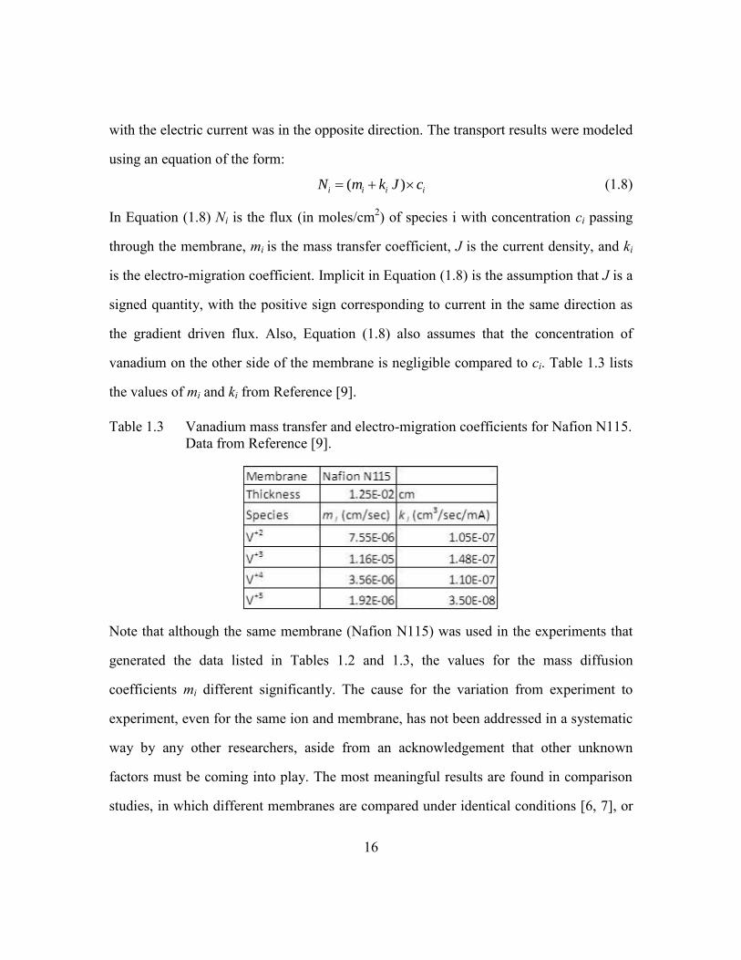
with the electric current was in the opposite direction. The transport results were modeled
using an equation of the form:
( )i i i iN m k J c (1.8)
In Equation (1.8) Ni is the flux (in moles/cm2) of species i with concentration ci passing
through the membrane, mi is the mass transfer coefficient, J is the current density, and ki
is the electro-migration coefficient. Implicit in Equation (1.8) is the assumption that J is a
signed quantity, with the positive sign corresponding to current in the same direction as
the gradient driven flux. Also, Equation (1.8) also assumes that the concentration of
vanadium on the other side of the membrane is negligible compared to ci. Table 1.3 lists
the values of mi and ki from Reference [9].
Table 1.3 Vanadium mass transfer and electro-migration coefficients for Nafion N115.
Data from Reference [9].
Note that although the same membrane (Nafion N115) was used in the experiments that
generated the data listed in Tables 1.2 and 1.3, the values for the mass diffusion
coefficients mi different significantly. The cause for the variation from experiment to
experiment, even for the same ion and membrane, has not been addressed in a systematic
way by any other researchers, aside from an acknowledgement that other unknown
factors must be coming into play. The most meaningful results are found in comparison
studies, in which different membranes are compared under identical conditions [6, 7], or
17
a single membrane which is tested with only one parameter varied (i.e. current density for
the experiment reported in Reference [9]).
To date, the results reported by Luo and co-workers are the only ones published in
which the transport of vanadium has been measured across ion exchange membranes in
the presence of electrical current. The maximum current density used in these
experiments, 50 mA/cm2, is much less than the current densities that have been reported
in experiments with state-of-the-art VRB cells, in which current densities in excess of
500 mA/cm2 have been demonstrated [10,19]. Also, the use of a number of different
flow batteries in a complicated series/parallel arrangement makes the execution of
experiments to separate concentration changes from current effects unwieldy at best. A
novel new cell design which simplifies the measurement of transport in an operating
VRB configuration was developed for this thesis and is described in the next section.
1.5 TRIPLE MEMBRANE CELL
A special VRB cell was designed with the purpose of studying ion cross-over in
an operating VRB cell. Two additional electrolyte chambers are incorporated into a
standard VRB cell to form the triple-membrane cell. Figure 1.8 shows a schematic
diagram of this cell. The triple membrane cell, which, for brevity, will be referred to as
the “XO” (for cross-over) cell, is a conventional VRB with positive and negative
electrolyte flow chambers, indicated in Figure 1.8 as the “V+” and “V-” chambers. Two
additional chambers, labeled “+XO” and “–XO”, are filled with sulfuric acid which is
circulated through two reservoirs using two additional flow circuits. Three ion exchange
membranes separate the four different chambers of the cell. The strength of the sulfuric
acid pumped through the XO chambers is adjusted to match the sulfate concentration of
the anolyte and catholyte.

18
Figure 1.8 Triple Membrane Cell Schematic Diagram.
The XO chambers act like a salt bridge connecting the V+ and V- chambers,
allowing a flux of H+ ions to pass through the +XO and –XO chambers during charge and
discharge. Anolyte and catholyte ions which cross-over through the outer ion exchange
membranes are collected in the –XO and +XO chambers respectively. Transport into the
XO chambers is dominated by the flux of ions from the adjacent V+ and V- chambers,
since the concentration gradient across the outer membranes is several orders of
magnitude greater than the gradient across the center membrane. All of the cross-over
transport data in this thesis was collected with the XO cell.
The XO cell proved to be very successful for measuring the transport of vanadium
with and without electrical current. Experiments with current densities up to 900 mA/cm2
were successfully run with the cell. The exact details and operating conditions will be
discussed in Chapter 3.

19
Chapter 2: Optical Measurement of Vanadium Ion Concentrations and
Transport Coefficients
In this chapter methods are described to determine the composition of mixtures of
vanadium ions using absorption spectroscopy. The calculation of vanadium transport
coefficients is demonstrated with spectroscopy data from a simple experiment.
2.1 BEER’S LAW FOR MIXTURES OF ABSORBING SPECIES
In many cases, the intensity of light transmitted through a liquid media varies
exponentially with the path length l:
0
NlI I e (2.1)
where is the cross section for light absorption and N is the number density of the
absorbing molecules. The absorbance is defined as the negative logarithm (base 10) of
the fraction of transmitted light:
0
logI
AI
(2.2)
Substituting (2.1) into (2.2) yields Beer’s Law, which relates the absorbance to the
properties and number density of the absorbing molecules:
0.434A Nl (2.3)
If Beer’s law is valid for a particular substance, then equations (2.1) through (2.3)
are valid, and the absorbance is proportional to the concentration of the absorbing
molecules. Equation (2.3) is often recast in terms of molar concentration c and molar
absorptivity a as:
A acl (2.4)
If a mixture of two absorbing species and is prepared, then the absorptivity of the
mixture will often behave linearly with the concentrations of the component species c
and c according to:

20
bA a c l a c l (2.5)
where a and a are the molar absorptivity of species and
Equation (2.5) implies that if the absorptivity is measured at two different
wavelengths, 1 and 2 , then the concentrations of the two species can be found by
solving the following system of equations:
1 1 1
2 2 2
( ) ( ) ( )
( ) ( ) ( )
A a c l a c l
A a c l a c l
(2.6)
In practice, the absorption spectra of reference samples of known concentrations of and
are used to eliminate the molar absorptivity and path length by using the relationship:
( ) ( ) ref
j i j i jA a c l (2.7)
where ( )j iA is the absorptivity at wavelength i of the reference sample consisting of
species j with concentration ref
jc . Using (2.7) the system of equations (2.6) can be
rewritten in terms of the absorptivity of the reference samples as:
1 1 1
2 2 2
( ) ( ) ( )
( ) ( ) ( )
ref ref
ref ref
ccA A A
c c
ccA A A
c c
(2.8)
The solution of (2.8) yields the coefficients / refc c and / refc c , the concentrations of
species and relative to the reference sample concentrations.
21
2.2 SPECTROSCOPIC ANALYSIS OF VANADIUM ION MIXTURES
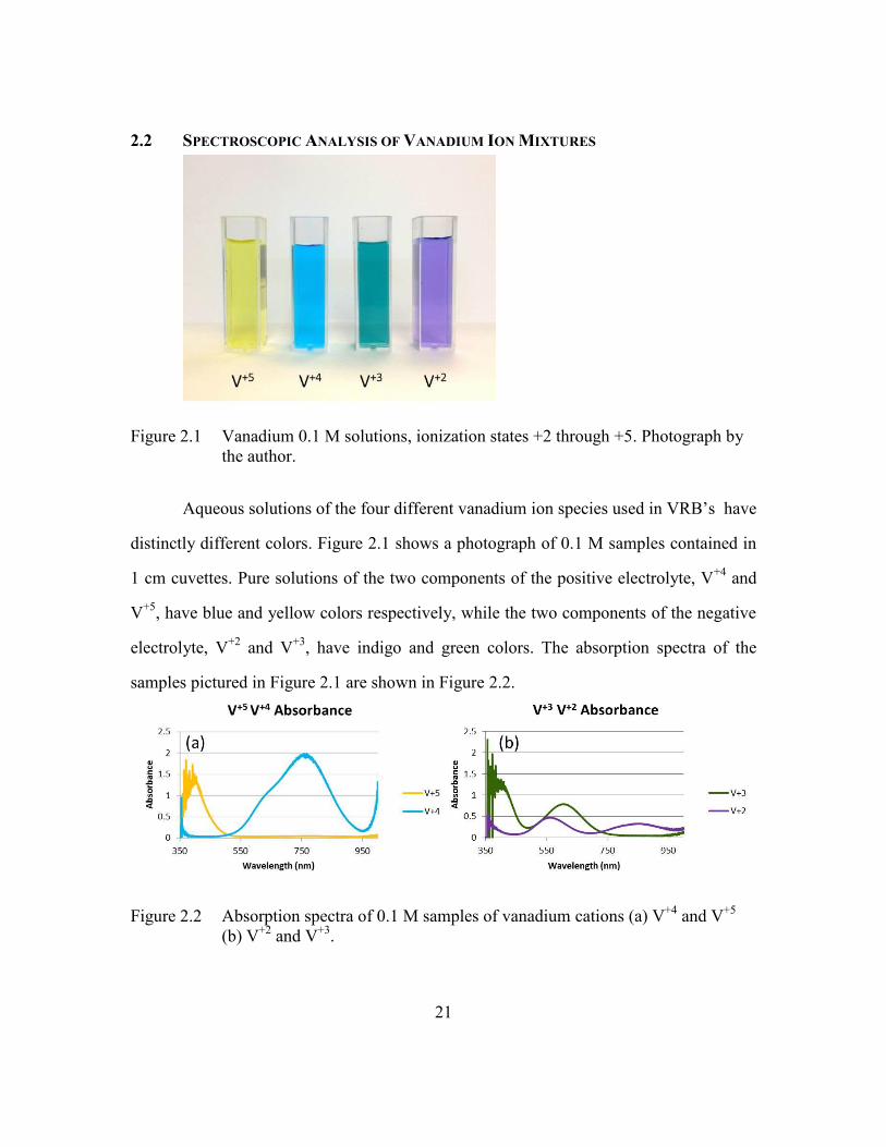
Figure 2.1 Vanadium 0.1 M solutions, ionization states +2 through +5. Photograph by
the author.
Aqueous solutions of the four different vanadium ion species used in VRB’s have
distinctly different colors. Figure 2.1 shows a photograph of 0.1 M samples contained in
1 cm cuvettes. Pure solutions of the two components of the positive electrolyte, V+4
and
V+5
, have blue and yellow colors respectively, while the two components of the negative
electrolyte, V+2
and V+3
, have indigo and green colors. The absorption spectra of the
samples pictured in Figure 2.1 are shown in Figure 2.2.
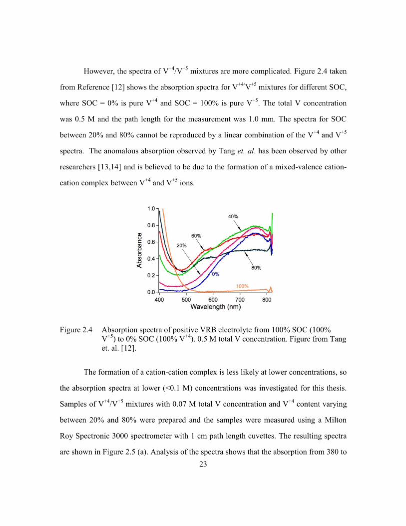
Figure 2.2 Absorption spectra of 0.1 M samples of vanadium cations (a) V+4
and V+5
(b) V+2
and V+3
.

22
Because of these distinctly different colors, several research groups have investigated the
use of UV/VIS absorption spectroscopy to determine the state of charge (SOC) of the
electrolytes used in VRB’s [11,12].
A requirement for spectrophotometry of a mixture of vanadium ions to be useful
for determining the composition mixture is that the spectrum must obey Equation (2.5),
which states that the mixture spectrum is a linear combination of the spectra of the
component species. Tang et. al. measured the absorption spectra of mixtures of V+2
and
V+3
typical of the negative electrolyte of a VRB [12]. Figure 2.3 taken from Reference
[12] shows the absorption spectra of the negative electrolyte for different SOC, where
SOC = 0% is pure V+3
and SOC = 100% is pure V+2
. The sum of the concentrations of
V+2
and V+3
was kept constant at 1 M, and the path length of the sample used was 0.5
mm. The spectra in Figure 2.3 are well represented by linear combinations of the V+2
and
V+3
spectra with the coefficients consistent with the SOC of the electrolyte mixture. The
authors conclude that absorption spectroscopy is useful for determining the SOC of the
VRB negative electrolyte.
Figure 2.3 Absorption spectra of negative VRB electrolytes from 0% to 100% SOC, 1
M total V concentration. Figure from Tang et.al. [12].
23
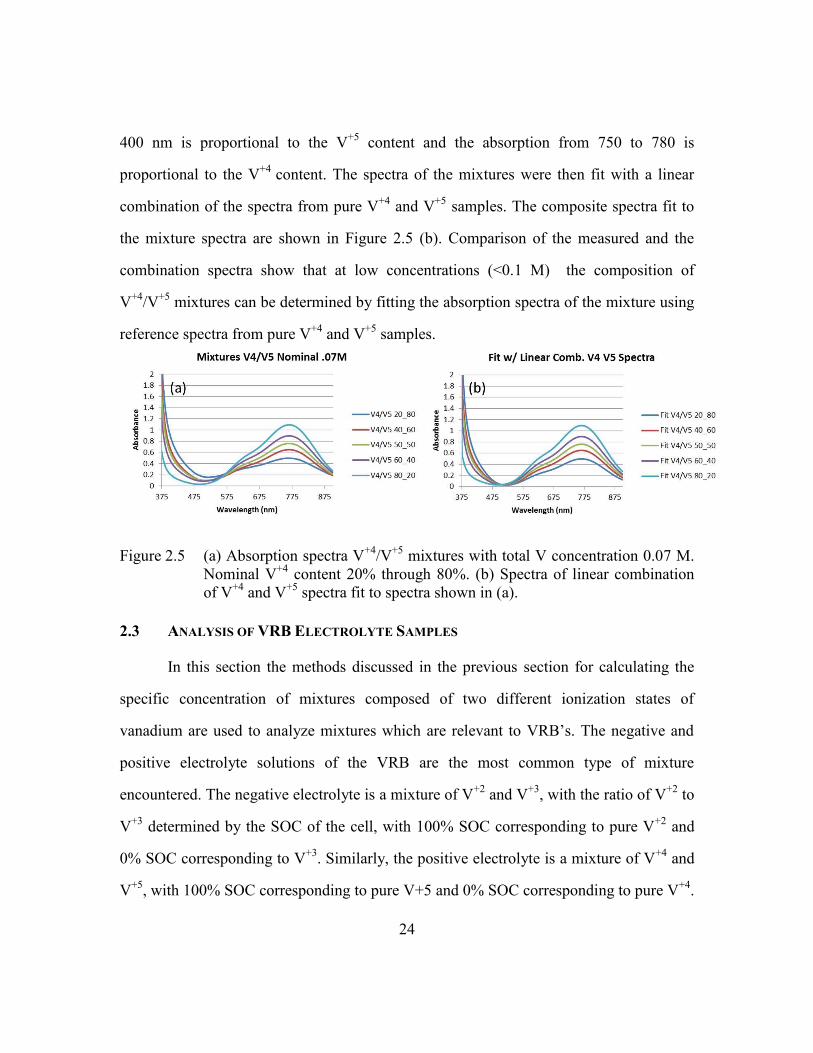
However, the spectra of V+4
/V+5
mixtures are more complicated. Figure 2.4 taken
from Reference [12] shows the absorption spectra for V+4/
V+5
mixtures for different SOC,
where SOC = 0% is pure V+4
and SOC = 100% is pure V+5
. The total V concentration
was 0.5 M and the path length for the measurement was 1.0 mm. The spectra for SOC
between 20% and 80% cannot be reproduced by a linear combination of the V+4
and V+5
spectra. The anomalous absorption observed by Tang et. al. has been observed by other
researchers [13,14] and is believed to be due to the formation of a mixed-valence cation-
cation complex between V+4
and V+5
ions.
Figure 2.4 Absorption spectra of positive VRB electrolyte from 100% SOC (100%
V+5
) to 0% SOC (100% V+4
). 0.5 M total V concentration. Figure from Tang
et. al. [12].
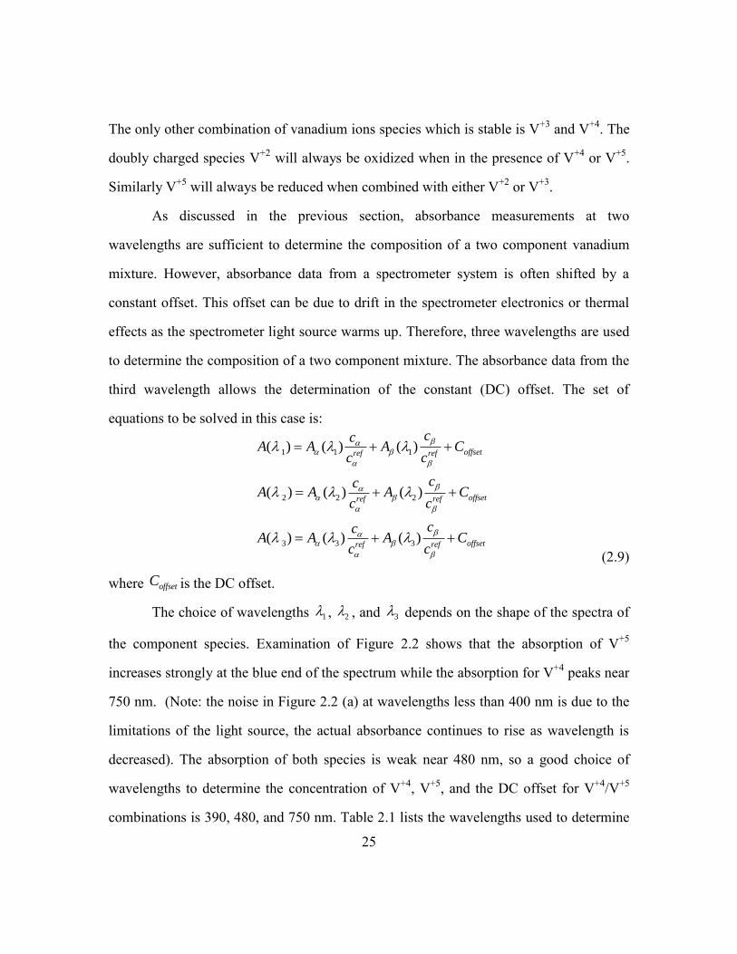
The formation of a cation-cation complex is less likely at lower concentrations, so
the absorption spectra at lower (<0.1 M) concentrations was investigated for this thesis.
Samples of V+4
/V+5
mixtures with 0.07 M total V concentration and V+4
content varying
between 20% and 80% were prepared and the samples were measured using a Milton
Roy Spectronic 3000 spectrometer with 1 cm path length cuvettes. The resulting spectra
are shown in Figure 2.5 (a). Analysis of the spectra shows that the absorption from 380 to
24
400 nm is proportional to the V+5
content and the absorption from 750 to 780 is
proportional to the V+4
content. The spectra of the mixtures were then fit with a linear
combination of the spectra from pure V+4
and V+5
samples. The composite spectra fit to
the mixture spectra are shown in Figure 2.5 (b). Comparison of the measured and the
combination spectra show that at low concentrations (<0.1 M) the composition of
V+4
/V+5
mixtures can be determined by fitting the absorption spectra of the mixture using
reference spectra from pure V+4
and V+5
samples.
Figure 2.5 (a) Absorption spectra V+4
/V+5
mixtures with total V concentration 0.07 M.
Nominal V+4
content 20% through 80%. (b) Spectra of linear combination
of V+4
and V+5
spectra fit to spectra shown in (a).
2.3 ANALYSIS OF VRB ELECTROLYTE SAMPLES
In this section the methods discussed in the previous section for calculating the
specific concentration of mixtures composed of two different ionization states of
vanadium are used to analyze mixtures which are relevant to VRB’s. The negative and
positive electrolyte solutions of the VRB are the most common type of mixture
encountered. The negative electrolyte is a mixture of V+2
and V+3
, with the ratio of V+2
to
V+3
determined by the SOC of the cell, with 100% SOC corresponding to pure V+2
and
0% SOC corresponding to V+3
. Similarly, the positive electrolyte is a mixture of V+4
and
V+5
, with 100% SOC corresponding to pure V+5 and 0% SOC corresponding to pure V+4
.
25
The only other combination of vanadium ions species which is stable is V+3
and V+4
. The
doubly charged species V+2
will always be oxidized when in the presence of V+4
or V+5
.
Similarly V+5
will always be reduced when combined with either V+2
or V+3
.
As discussed in the previous section, absorbance measurements at two
wavelengths are sufficient to determine the composition of a two component vanadium
mixture. However, absorbance data from a spectrometer system is often shifted by a
constant offset. This offset can be due to drift in the spectrometer electronics or thermal
effects as the spectrometer light source warms up. Therefore, three wavelengths are used
to determine the composition of a two component mixture. The absorbance data from the
third wavelength allows the determination of the constant (DC) offset. The set of
equations to be solved in this case is:
1 1 1
2 2 2
3 3 3
( ) ( ) ( )
( ) ( ) ( )
( ) ( ) ( )
offsetref ref
offsetref ref
offsetref ref
ccA A A C
c c
ccA A A C
c c
ccA A A C
c c
(2.9)
where offsetC is the DC offset.
The choice of wavelengths 1 , 2 , and 3 depends on the shape of the spectra of
the component species. Examination of Figure 2.2 shows that the absorption of V+5
increases strongly at the blue end of the spectrum while the absorption for V+4
peaks near
750 nm. (Note: the noise in Figure 2.2 (a) at wavelengths less than 400 nm is due to the
limitations of the light source, the actual absorbance continues to rise as wavelength is
decreased). The absorption of both species is weak near 480 nm, so a good choice of
wavelengths to determine the concentration of V+4
, V+5
, and the DC offset for V+4
/V+5
combinations is 390, 480, and 750 nm. Table 2.1 lists the wavelengths used to determine

26
the concentrations of the component species (relative to the reference concentrations) and
the DC offset for V+4
/V+5
, V+3
/V+4
, and V+2
/V+3
mixture combinations.
Table 2.1 Wavelengths to determine vanadium mixture composition for specific ion
combinations.
Figure 2.6 Sample mixture spectra and fit to reference spectra (labeled “Sum V4 V5”
etc) for (a) V+5
/V+4
(b) V+4/
V+3
and (c) V+3
/V+2
mixtures.

27
Figure 2.6 shows the absorbance spectra of V+4
/V+5
, V+3
/V+4
, and V+2
/V+3
mixtures typical of the samples measured in this thesis. The spectrum shown in Figure
2.6 (a) is from a sample in which V+4
and V+5
ions diffused from the positive electrolyte
of a VRB through an ion exchange membrane and were collected in sulfuric acid. Also
plotted in Figure 2.6 (a) is the representation of the mixture spectrum using a
combination of reference V+4
and V+5
spectra. Similarly, Figure 2.6 (b) and (c) show the
spectra of mixtures of V+3
/ V+4
, and V+2
/V+3
, collected in a similar manner, along with
the representations of the mixture spectra using reference spectra. In all cases the linear
combinations of the reference spectra provide an accurate representation of the mixture
spectra. Using the absorbance spectra of the 0.1 M samples shown in Figure 2.2 to
calibrate the reference absorbance data, the composition of the mixtures whose spectra
are shown in Figure 2.6 were calculated using Equation (2.9) and are tabulated in Table
2.2:
Table 2.2 Ionic concentrations determined from spectra from Figure 2.6 using
reference spectra from Figure 2.2.
The uncertainty in the absolute values of the concentrations shown in Table 2.2 is
approximately 20%, mainly due to uncertainty in the concentration of the reference
samples. However, as will be shown later, the determination of vanadium ion transport
coefficients depends on the ratio of vanadium concentrations in the different chambers of
the experimental cell, so the uncertainty in the calibration coefficients does not lead to
significant error in the vanadium transport coefficients.

28
2.4 CALCULATION OF MEMBRANE TRANSPORT COEFFICIENTS
In the preceding section it was shown that the composition of dilute (<0.1 M)
mixtures of vanadium ions can be determined by absorption spectroscopy of the
solutions. Higher concentration vanadium ion solutions (~ 1 to 2 M) are easily analyzed
by diluting the samples by a factor of 10 to 20 to reduce the sample concentration to 0.1
M or less. Using this method the composition any mixtures of V+2
/V+3
, V+3
/V+4
, or
V+4
/V+5
encountered in VRB experiments can be analyzed. In this section the calculation
of membrane transport coefficients from absorption data is discussed in detail for a
typical experiment using the XO cell.
Figure 2.7 Experimental setup for a vanadium membrane transport experiment.
A schematic of the experimental arrangement is shown in Figure 2.7. In the
chamber labeled V+, a mixture of V+4
/V+5
is circulated using an external pump and
reservoir. An ion exchange membrane (Nafion N212) separates the V+ chamber from the
neighboring chamber labeled +XO. A solution of sulfuric acid (with sulfate concentration
matching the sulfate concentration of the V+ solution) is pumped through the +XO
chamber. A second membrane (Nafion N117) separates +XO from the next chamber,
labeled –XO. A solution of sulfuric acid identical to that pumped through +XO is

29
pumped through –XO. A third membrane (N212) separates –XO from the chamber
labeled V-. A mixture of V+2
/V+3
circulates through the V- chamber. The total vanadium
concentrations and sulfate concentrations of the V+ and V- solutions match. Graphite felt
porous electrodes fill the flow regions of all four chambers.
In this experiment, no current is flowing through the cell. Transport of V+4
and
V+5
will occur between the V+ and +XO chambers driven by the concentration gradient
across the N212 membrane. Similarly transport of V+2
and V+3
will occur across the
N212 membrane separating the V- and –XO chambers. The transport between the V+ or
V- chambers and the adjacent +XO or –XO chamber will be much greater than any
transport between the –XO and +XO chambers because the vanadium concentration
difference across the outer N212 membranes (of order 1 M) is much greater than the
concentration difference across the center N117 membrane (of order 0.01 M).
The experiment is initiated by pumping sulfuric acid solution through the +XO
and –XO chambers while a mixture of V+4
/V+5
is pumped through V+ and V+2
/V+3
is
pumped through V-. The transport of vanadium ions across the ion exchange membrane
is modeled as a diffusion process, with the ion flux being described by Fick’s law:
i i iN D c (2.10)
In the above expression iN is the ion flux (in moles/cm2sec) of species i through the
membrane, Di is the diffusion coefficient for species i, and ic is the concentration
gradient across the membrane. The following analysis is made with regards to transport
from the V+ chamber to the +XO chamber, the analysis for transport between V- and
–XO is analogous. With the assumption that the concentration on the V+ side of the
membrane is much greater than the concentration on the +XO side, the concentration
gradient can be approximated as:
30
V
ii
cc
l
(2.11)
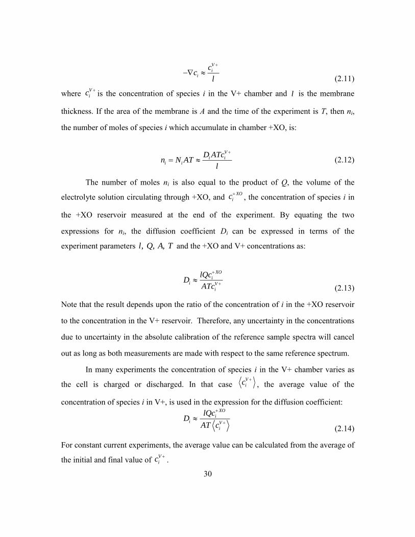
where V
ic is the concentration of species i in the V+ chamber and l is the membrane
thickness. If the area of the membrane is A and the time of the experiment is T, then ni,
the number of moles of species i which accumulate in chamber +XO, is:
V
i ii i
D ATcn N AT
l
(2.12)
The number of moles ni is also equal to the product of Q, the volume of the
electrolyte solution circulating through +XO, and XO
ic, the concentration of species i in
the +XO reservoir measured at the end of the experiment. By equating the two
expressions for ni, the diffusion coefficient Di can be expressed in terms of the
experiment parameters , , , l Q A T and the +XO and V+ concentrations as:
XO
ii V
i
lQcD
ATc
(2.13)
Note that the result depends upon the ratio of the concentration of i in the +XO reservoir
to the concentration in the V+ reservoir. Therefore, any uncertainty in the concentrations
due to uncertainty in the absolute calibration of the reference sample spectra will cancel
out as long as both measurements are made with respect to the same reference spectrum.
In many experiments the concentration of species i in the V+ chamber varies as
the cell is charged or discharged. In that case V
ic
, the average value of the
concentration of species i in V+, is used in the expression for the diffusion coefficient:
XO
ii V
i
lQcD
AT c
(2.14)
For constant current experiments, the average value can be calculated from the average of
the initial and final value of V
ic .

31
A useful quantity for comparing ion cross-over rates for different membrane types
and thickness is the mass transfer coefficient m, which is the proportionality constant
relating the flux of species i to the difference in concentrations across the membrane. For
of cross-over between V+ and +XO chambers, the flux is ( )V XO
i i i iN m c c . With the
assumption that V XO
i ic c , and using equations (2.10) and (2.11), the mass transfer
coefficient mi can be expressed in terms of terms of the experimentally measured
concentrations in the V+ and +XO reservoirs as:
XO
i ii V
i
D Qcm
l AT c
(2.15)
Given mi, the cross-over flux from V+ to +XO is easily calculated as V
i i iN m c .
Figure 2.8 (a) V+ and V- Absorption Spectra (b) +XO and -XO Absorption Spectra,
XO cell with no current flow.
One mL samples of V+ and V- were collected before the experiment was run and
diluted by a factor of 10 to determine the initial vanadium concentrations. The vanadium
and sulfuric acid solution were then pumped through the cell for 3600 seconds, after
which samples of +XO and –XO solutions collected. Figure 2.8 shows the absorption
spectra of the V+, V-, +XO, and –XO samples. It is clear from Figure 2.8 that the spectra

32
of the +XO and –XO electrolytes closely resemble the spectra of V+ and V- samples
respectively.
Table 2.3 Experimental parameters, measured vanadium concentrations, and
calculated diffusion and mass transfer coefficients for zero current
experiment.
Table 2.3 lists the experimental parameters, the measured vanadium
concentrations (M), and the calculated diffusion and mass transfer coefficients for the
four vanadium ion species for this experiment. The calculation procedure discussed
above for determining the transport coefficients from absorption data for this simple
experiment is utilized for all of the experiments reported in this thesis. In most of the
experiments to be discussed later, current is flowing through the cell, and the
compositions of the V+ and V- electrolytes change during the experiment. In this case the
diffusion coefficient is calculated using (2.14) instead of (2.13). Also, as will be
discussed later in greater detail, the mechanism for transport is no longer purely diffusive;
electric field effects play an important role in determining transport rates when current is
present.
2.5 SUMMARY OF OPTICAL MEASUREMENT OF VANADIUM ION CONCENTRATIONS
AND TRANSPORT COEFFICIENTS
In this chapter, it was shown that absorption spectroscopy could be used to
determine the composition and concentration of vanadium ion mixtures encountered
when analyzing vanadium flow battery electrolytes. Problems in analyzing V+4
/V+5

33
mixtures which had been identified by other researchers were shown to be alleviated by
diluting the mixtures sufficiently. It was shown that, with the use of reference spectra of
known concentration samples of vanadium ions, measurements at three different
wavelengths provided sufficient information to decompose the spectrum of any vanadium
ion mixture and to determine the concentration of the different components. A formalism
was developed to calculate the diffusion and mass transfer coefficients of vanadium ions
across an ion exchange membrane using the concentrations determined from the
absorption spectra.

34
Chapter 3: Cross-over Measurements using the Triple Membrane VRB
Cell
3.1 VANADIUM REDOX FLOW BATTERY OPERATION
Initial experiments were performed with the VRB cell shown in Figure 3.1. This
cell had a Nafion N117 membrane with 5 mm carbon felt porous electrodes. The cross
sectional area of the cell was 22.3 cm2. Flat Viton gaskets 1.5 mm thick sandwiched the
Nafion membrane and provided the sealing surfaces for the PVC frames. The entire
assembly was bolted together with machine screws and an external clamping assembly
provided pressure on the graphite current collectors which compressed the porous
electrodes to approximately 4 mm thickness when assembled. Brass plated external
electrodes placed between the back of the graphite current collectors and the clamping
plates provided an attachment for the external power supplies. In later experiments, the
brass-plated electrodes were replaced with electrodes cut from 3 mm graphite stock to
avoid corrosion problems due to leaking electrolytes. This cell was used to prepare the
V+5
and V+2
electrolytes from V+4
electrolyte using the process described in Chapter 2.
Figure 3.1 VRB Cell for initial experiments. N117 Membrane, no current defining
aperture.

35
Figure 3.2 shows current-voltage and power density data for the cell with the
original N117 membrane and a subsequent experiment in which a N212 ion exchange
membrane was used. A potentiostat (Princeton Applied Research PAR 2273 with current
booster) was used to apply a slow current ramp from zero to 8 amps over 400 seconds.
Electrolyte solutions with 1 M total vanadium concentration and 4 M total sulfate
concentration were used in these experiments. The data in Figure 3.2 (a) shows that the
output voltage at the highest currents was slightly higher with the N212 membrane
compared to the N117 data, which was due to the lower series resistance of the thinner
N212 material (50 microns) compared to N117 (180 microns). Figure 3.2 (b) shows the
power density versus current density curves derived from the data in Figure 3.2 (a). The
peak power achieved by the cell with the N212 membrane was 261 mW/cm2 at a current
density of 342 mA/cm2.
Figure 3.2 (a) Current vs Voltage (b) Power Density vs Current Density for VRB with
N117 and N212 membranes
3.2 TRIPLE MEMBRANE (XO) CELL
The motivation for the development of the triple membrane, or XO cell, was
discussed in Chapter 1. The XO cell is a modified VRB cell identical to the one used in
the initial experiments described in the previous section, with two additional flow
36
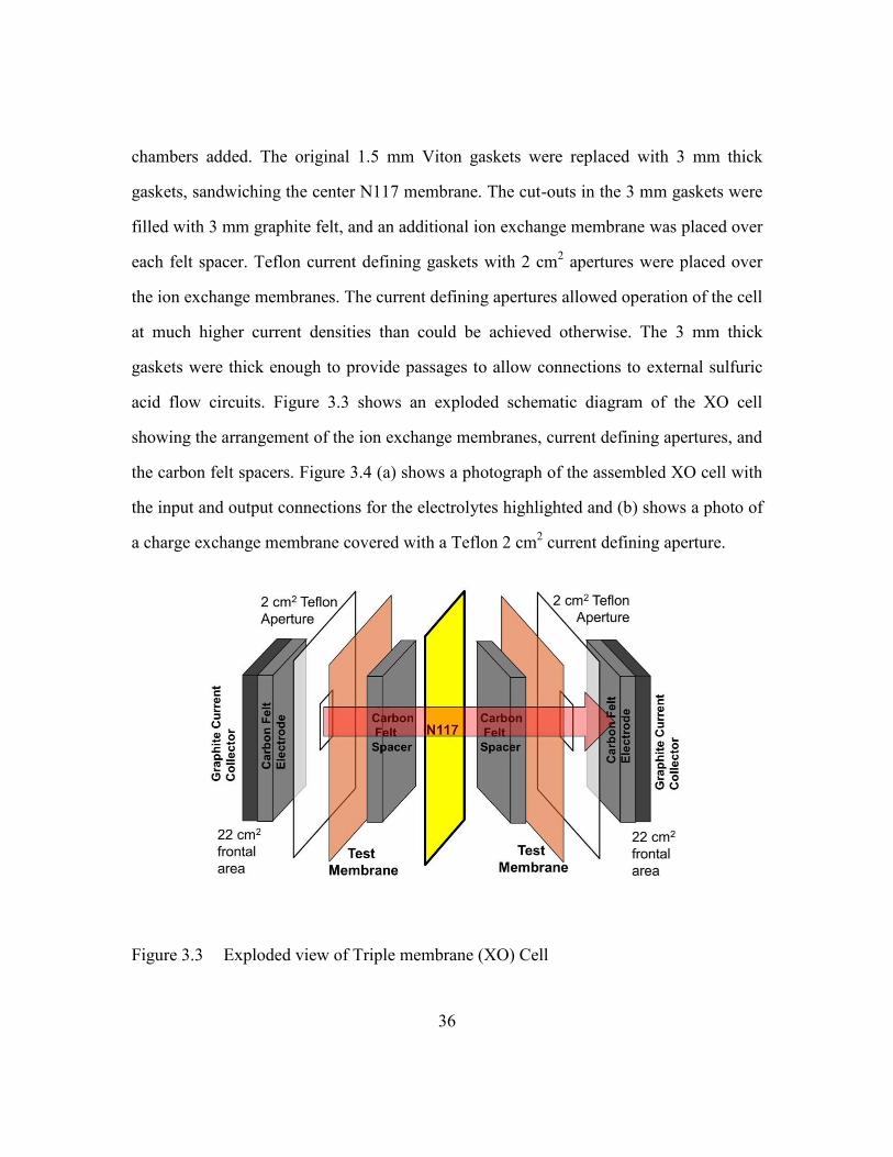
chambers added. The original 1.5 mm Viton gaskets were replaced with 3 mm thick
gaskets, sandwiching the center N117 membrane. The cut-outs in the 3 mm gaskets were
filled with 3 mm graphite felt, and an additional ion exchange membrane was placed over
each felt spacer. Teflon current defining gaskets with 2 cm2 apertures were placed over
the ion exchange membranes. The current defining apertures allowed operation of the cell
at much higher current densities than could be achieved otherwise. The 3 mm thick
gaskets were thick enough to provide passages to allow connections to external sulfuric
acid flow circuits. Figure 3.3 shows an exploded schematic diagram of the XO cell
showing the arrangement of the ion exchange membranes, current defining apertures, and
the carbon felt spacers. Figure 3.4 (a) shows a photograph of the assembled XO cell with
the input and output connections for the electrolytes highlighted and (b) shows a photo of
a charge exchange membrane covered with a Teflon 2 cm2 current defining aperture.
Figure 3.3 Exploded view of Triple membrane (XO) Cell
37
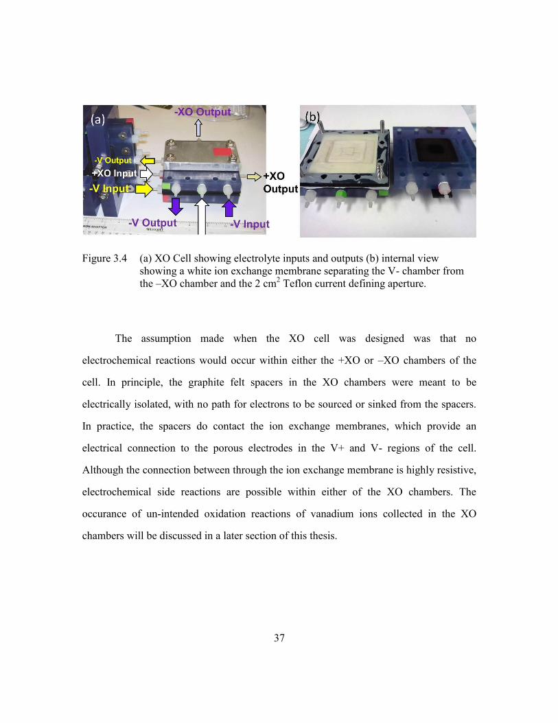
Figure 3.4 (a) XO Cell showing electrolyte inputs and outputs (b) internal view
showing a white ion exchange membrane separating the V- chamber from
the –XO chamber and the 2 cm2 Teflon current defining aperture.
The assumption made when the XO cell was designed was that no
electrochemical reactions would occur within either the +XO or –XO chambers of the
cell. In principle, the graphite felt spacers in the XO chambers were meant to be
electrically isolated, with no path for electrons to be sourced or sinked from the spacers.
In practice, the spacers do contact the ion exchange membranes, which provide an
electrical connection to the porous electrodes in the V+ and V- regions of the cell.
Although the connection between through the ion exchange membrane is highly resistive,
electrochemical side reactions are possible within either of the XO chambers. The
occurance of un-intended oxidation reactions of vanadium ions collected in the XO
chambers will be discussed in a later section of this thesis.
38
3.4 FULL CELL MODE XO EXPERIMENTS
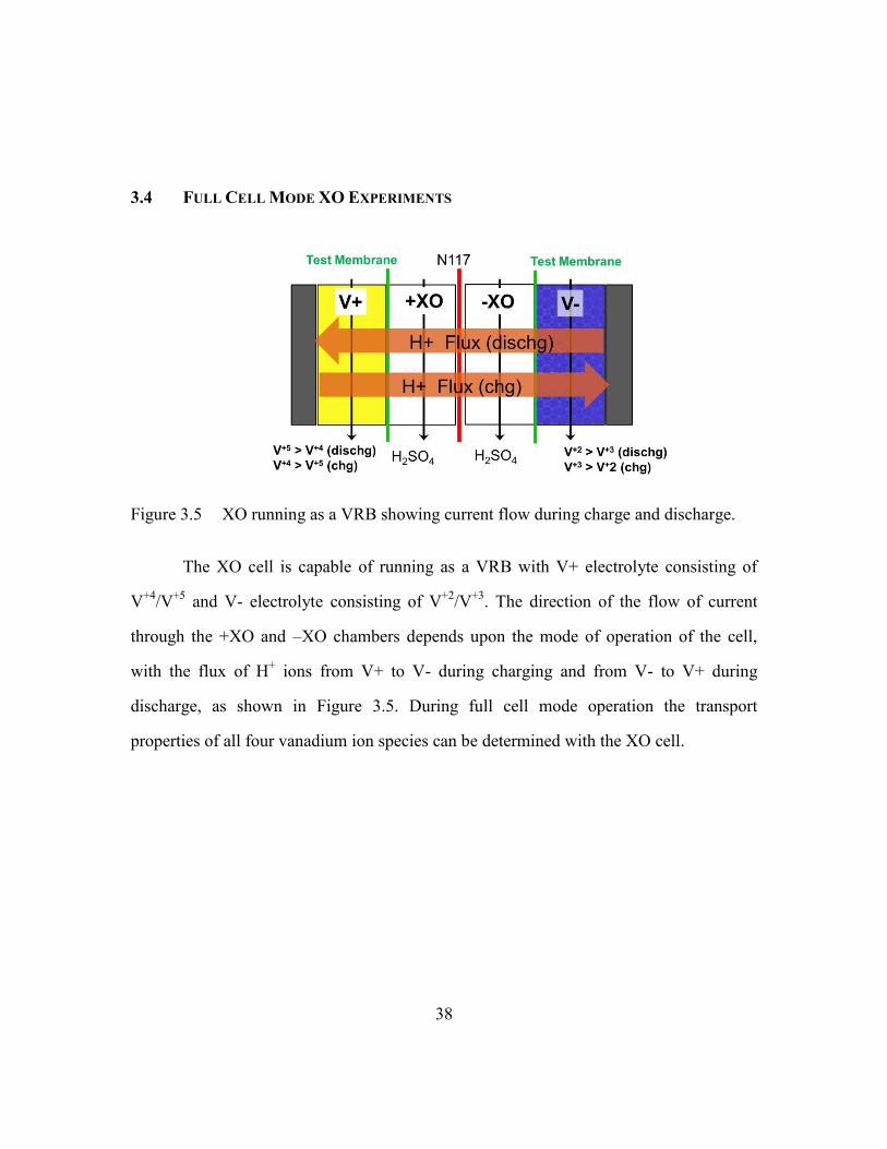
Figure 3.5 XO running as a VRB showing current flow during charge and discharge.
The XO cell is capable of running as a VRB with V+ electrolyte consisting of
V+4
/V+5
and V- electrolyte consisting of V+2
/V+3
. The direction of the flow of current
through the +XO and –XO chambers depends upon the mode of operation of the cell,
with the flux of H+ ions from V+ to V- during charging and from V- to V+ during
discharge, as shown in Figure 3.5. During full cell mode operation the transport
properties of all four vanadium ion species can be determined with the XO cell.
39
Figure 3.6 Experimental Arrangement for XO Cell Measurements.
Figure 3.6 shows the experimental layout for full cell mode cross-over
experiments with the XO cell. A Gilson Minipuls 3 peristaltic pump with four separate
flow channels provided circulation for the V+, V-, +XO, and –XO flow circuits. All the
reservoirs were purged with an inert Argon atmosphere to prevent unintended oxidation
of the vanadium ions. A conventional VRB shared the V+ and V– flow circuits. If the
XO cell was run as a conventional VRB, the second VRB cell was used to measure the
open circuit voltage (OCV) which gave an indication of the SOC of the vanadium
electrolyte solutions. Alternatively, the second VRB could be used to run a charge or
discharge cycle while the XO cell was run with zero current. In this manner the effect of
current flow on vanadium transport could easily be isolated from that of V+/V–
electrolyte composition changes due to SOC changes.

40
Figure 3.7 Full Cell Mode I-V curve for XO cell operating as a VRB.
Figure 3.7 shows the current-voltage curve for a full cell mode experiment in
which the XO cell was running a 600 mA discharge for 10800 seconds. An Arbin BT-
2000 battery tester was used to control the current and log the data. The voltage dropped
from 1.5 V to 0.65 V when the current flow was initiated. At the end of the experiment
the output voltage had dropped to below 0.1 V. When the current flow was interrupted an
open circuit voltage of 1.25 V was measured. The total vanadium concentration of the
anolyte and catholyte was 0.7 M and the total sulfate concentration was 3.7 M. The +XO
and –XO reservoirs were filled with 30 mL each of fresh 4 M sulfuric acid before the
start of the experiment. A trapped volume of 3 mL was assumed for each XO chamber
and was added to the total volume of liquid contained in the +XO and –XO reservoirs
when mass transfer coefficients were calculated from the raw data.
The initial and final SOC of the electrolytes in the V+ and V- chambers was
determined by taking 1 mL samples of the anolyte and catholyte at the beginning and end
of the experiment. The samples were diluted 10:1 and then analyzed using the UV/VIS
absorption spectroscopy method discussed earlier. Samples of the +XO and –XO
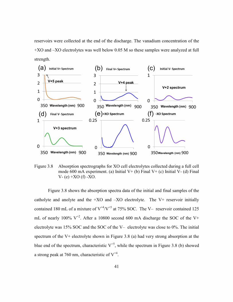
41
reservoirs were collected at the end of the discharge. The vanadium concentration of the
+XO and –XO electrolytes was well below 0.05 M so these samples were analyzed at full
strength.
Figure 3.8 Absorption spectrographs for XO cell electrolytes collected during a full cell
mode 600 mA experiment. (a) Initial V+ (b) Final V+ (c) Initial V- (d) Final
V- (e) +XO (f) -XO.
Figure 3.8 shows the absorption spectra data of the initial and final samples of the
catholyte and anolyte and the +XO and –XO electrolyte. The V+ reservoir initially
contained 180 mL of a mixture of V+4
/V+5
at 75% SOC. The V– reservoir contained 125
mL of nearly 100% V+2
. After a 10800 second 600 mA discharge the SOC of the V+
electrolyte was 15% SOC and the SOC of the V– electrolyte was close to 0%. The initial
spectrum of the V+ electrolyte shown in Figure 3.8 (a) had very strong absorption at the
blue end of the spectrum, characteristic V+5
, while the spectrum in Figure 3.8 (b) showed
a strong peak at 760 nm, characteristic of V+4
.
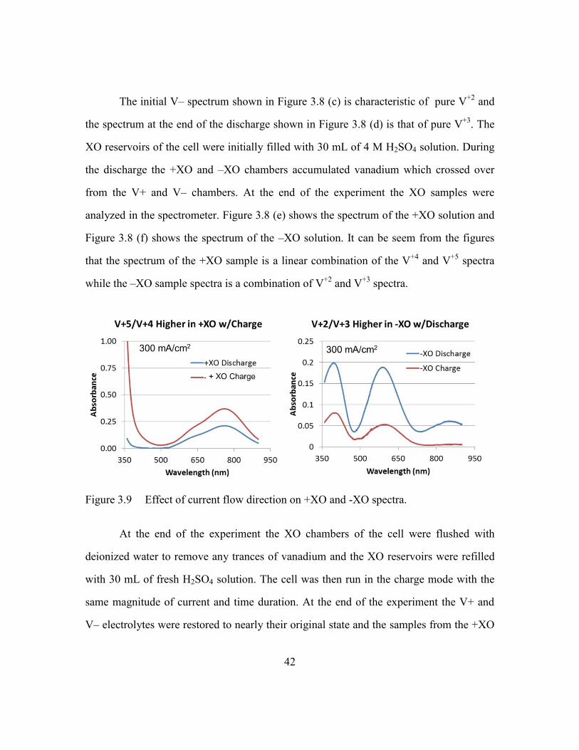
42
The initial V– spectrum shown in Figure 3.8 (c) is characteristic of pure V+2
and
the spectrum at the end of the discharge shown in Figure 3.8 (d) is that of pure V+3
. The
XO reservoirs of the cell were initially filled with 30 mL of 4 M H2SO4 solution. During
the discharge the +XO and –XO chambers accumulated vanadium which crossed over
from the V+ and V– chambers. At the end of the experiment the XO samples were
analyzed in the spectrometer. Figure 3.8 (e) shows the spectrum of the +XO solution and
Figure 3.8 (f) shows the spectrum of the –XO solution. It can be seem from the figures
that the spectrum of the +XO sample is a linear combination of the V+4
and V+5
spectra
while the –XO sample spectra is a combination of V+2
and V+3
spectra.
Figure 3.9 Effect of current flow direction on +XO and -XO spectra.
At the end of the experiment the XO chambers of the cell were flushed with
deionized water to remove any trances of vanadium and the XO reservoirs were refilled
with 30 mL of fresh H2SO4 solution. The cell was then run in the charge mode with the
same magnitude of current and time duration. At the end of the experiment the V+ and
V– electrolytes were restored to nearly their original state and the samples from the +XO

43
and –XO reservoirs were collected for analysis. Figure 3.9 compares the spectra for the
+XO and –XO solutions for the charge and discharge experiments.
It can be seen from Figure 3.9 that the absorption, and hence vanadium
concentration, in the +XO electrolyte was higher during charge than discharge, while the
reverse was true in the –XO electrolyte. During charge mode, the H+ flux was in the V+
to V– direction, so the H+ flux and the electric field were parallel with the direction of
concentration gradient driven flux of V+4
/V+5
into the +XO chamber and opposite to the
direction of the concentration gradient driven flux of V+2
/V+3
from the V– chamber into
the –XO chamber. Transport was enhanced when the electric field and the concentration
gradient were in the same direction and suppressed when the electric field was in the
opposite direction. The changes in vanadium transport with current direction observed in
this experiment are in agreement the results reported in [9] from the mixed V/Fe flow
battery experiments.
3.5 ELECTRIC FIELD EFFECT ON TRANSPORT COEFFICIENTS
At the end of Chapter 2, the calculation of membrane transport coefficients was
described for an experiment in which the XO cell was run without current. For the zero
current case the flux of ions of species i was assumed to be due to diffusion alone:
i i iN D c (3.1)
The general expression for the flux of ions of species i due to diffusion and electro-
migration is given by the Nernst-Planck equation [15]:
i i i i i iN D c z c (3.2)
where zi is the charge number, i is the mobility, and is the gradient of the
electrostatic potential. At the end of Chapter 2, it was shown that a suitable
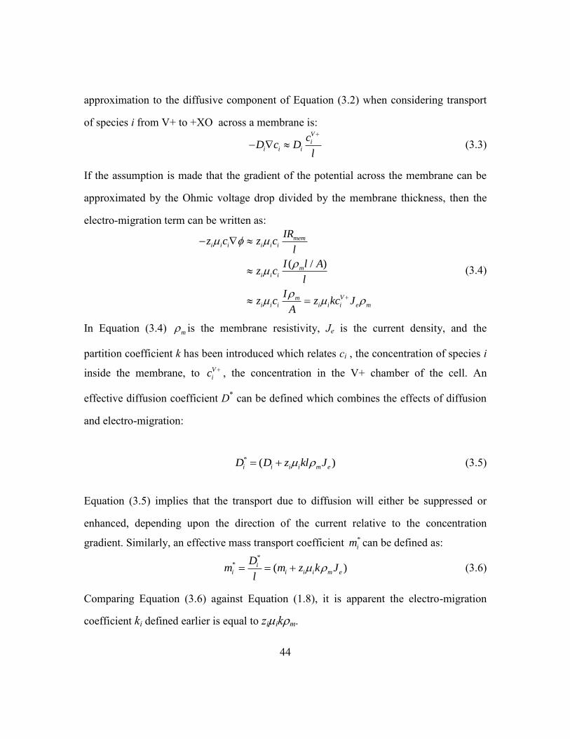
44
approximation to the diffusive component of Equation (3.2) when considering transport
of species i from V+ to +XO across a membrane is:
V
ii i i
cD c D
l
(3.3)
If the assumption is made that the gradient of the potential across the membrane can be
approximated by the Ohmic voltage drop divided by the membrane thickness, then the
electro-migration term can be written as:
( / )
memi i i i i i
mi i i
Vmi i i i i i e m
IRz c z c
l
I l Az c
l
Iz c z kc J
A
(3.4)
In Equation (3.4) m is the membrane resistivity, Je is the current density, and the
partition coefficient k has been introduced which relates ci , the concentration of species i
inside the membrane, to V
ic , the concentration in the V+ chamber of the cell. An
effective diffusion coefficient D* can be defined which combines the effects of diffusion
and electro-migration:
* ( )i i i i m eD D z kl J (3.5)
Equation (3.5) implies that the transport due to diffusion will either be suppressed or
enhanced, depending upon the direction of the current relative to the concentration
gradient. Similarly, an effective mass transport coefficient *
im can be defined as:
*
* ( )ii i i i m e
Dm m z k J
l (3.6)
Comparing Equation (3.6) against Equation (1.8), it is apparent the electro-migration
coefficient ki defined earlier is equal to ziikm.

45
The absorption spectrographs from the full cell 600 mA/cm2 discharge and charge
experiments with the XO cell can be analyzed using the same method as described at the
end of Chapter 2, but the transport coefficients Di and mi which are calculated using
Equations (2.14) and (2.15) should be interpreted as an effective diffusion coefficient *
iD
and *
im with the effects of electro-migration combined with concentration gradient driven
transport. The absorption spectrographs shown in Figure 3.8 were analyzed by fitting the
spectra to reference sample spectra to determine the composition of the samples in terms
of V+2
, V+3
, V+4
and V+5
concentrations. The effective transport coefficients for the 600
mA discharge experiment are listed in Table 3.1.
Table 3.1 Effective diffusion and mass transfer coefficients (600 mA Discharge)
Figure 3.9 shows that the amount of V+4
and V+5
transport into the +XO chamber
increased when the cell was run in charge mode, while V+2
and V+3
transport into the
–XO chamber decreased. The effective transport coefficients for the 600 mA charge
experiment listed in Table 3.2 and show that transport is greater for V+4
and V+5
and
smaller for V+2
and V+3
when the cell is run in charge mode compared to discharge mode.
Table 3.2 Effective diffusion and mass transfer coefficients (600 mA Charge)

46
In Figure 3.10 the effective mass transfer coefficients for V+5
, V+4
, V+3
, and V+2
are plotted as a function of mode of operation (charge, zero current, or discharge). It is
clear from Figure 3.10 that the simple linear variation in m* with current density implied
by Equation (3.6) is an oversimplification, since nonlinearities are apparent in the
changes in transport of V+4
, V+3
, and V+2
with current, and that extrapolating the linear
variation observed in the V+5
transport would rapidly lead to a negative transport
coefficient. The measurement in the variation in m* over a wider range of current
densities is the topic of Chapter 4, but it is clear that complicated behaviors are seen,
which lead to a more complicated picture of the interplay of diffusion and electro-
migration effects.
Figure 3.10 Effective mass transfer coefficients for (a) V+4
and V+5
and (b) V+2
and V+3
versus cell operation mode.
3.6 HALF CELL MODE XO EXPERIMENTS
Although the XO cell can be run as a VRB with V+4/
V+5
and V+2
/V+3
electrolyte
mixtures in the V+ and V- flow circuits, for many of the experiments reported in this
thesis, the XO cell was run half cell mode, in which both the V+ and V- sides of the cell
run the same redox reaction, with one side running the reaction in the oxidation direction
and the other in the reduction direction. Operation with just the V+4
/V+5
mixture

47
simplifies operation of the cell, removing the requirement to provide an inert atmosphere
purge in the V- reservoir to avoid oxidation of V+2
by atmospheric oxygen. Another
advantage of operation in half cell mode is that simultaneous measurement of the effect
of current flow in both the co- and counter directions to the gradient driven ion flux can
be performed in a single run.
Figure 3.11 (a) Experimental arrangement for V+4
/V+5
half cell mode experiments (b)
V+ absorption spectra (c) V– spectra (d) +XO spectrum (e) –XO spectrum.
Figure 3.11 shows the experimental arrangement and the absorption data spectra
for the XO cell running a 1200 mA charge cycle with the V+ electrolyte initially
consisting of nearly 100% V+4
and the V– electrolyte with nearly 100% V+5
. Figure 3.11
(a) shows the cell reactions and the direction of current flow through the cell. An Arbin
BT-2000 battery tester was used to drive the oxidation reaction V+4
V+5
on the V+
side and the reduction reaction V+5
V+4
on the V– side. The H+ flux was from V+
chamber to the V– chamber. After one hour of operation samples of electrolytes were
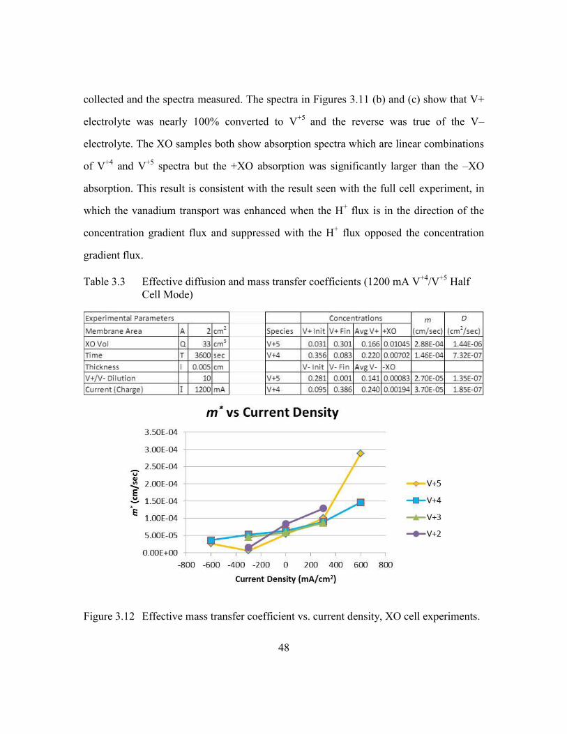
48
collected and the spectra measured. The spectra in Figures 3.11 (b) and (c) show that V+
electrolyte was nearly 100% converted to V+5
and the reverse was true of the V–
electrolyte. The XO samples both show absorption spectra which are linear combinations
of V+4
and V+5
spectra but the +XO absorption was significantly larger than the –XO
absorption. This result is consistent with the result seen with the full cell experiment, in
which the vanadium transport was enhanced when the H+ flux is in the direction of the
concentration gradient flux and suppressed with the H+ flux opposed the concentration
gradient flux.
Table 3.3 Effective diffusion and mass transfer coefficients (1200 mA V+4
/V+5
Half
Cell Mode)
Figure 3.12 Effective mass transfer coefficient vs. current density, XO cell experiments.

49
Figure 3.12 shows the effective mass transfer coefficient as a function of current
density for all of the experiments discussed so far (full cell mode 600 mA charge and
discharge, full cell mode zero current, half cell mode V+4
/V+5
1200 mA charge). Positive
current density corresponds to the direction of current flow in the same direction of the
concentration gradient driven flux (from V+ to +XO or V- to –XO), and negative current
density corresponds to current flow in the direction opposite to the concentration driven
flux. This convention is used for all of the data presented in the remainder of this thesis.
In all cases the transport parameters increase when the current is in the same direction as
the concentration driven flux and decrease when the current is in the opposite direction.
In the next chapter, results for experiments with a greater range of currents and for
different types of ion exchange membranes will be presented.
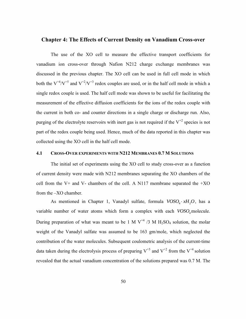
50
Chapter 4: The Effects of Current Density on Vanadium Cross-over
The use of the XO cell to measure the effective transport coefficients for
vanadium ion cross-over through Nafion N212 charge exchange membranes was
discussed in the previous chapter. The XO cell can be used in full cell mode in which
both the V+4
/V+5
and V+2
/V+3
redox couples are used, or in the half cell mode in which a
single redox couple is used. The half cell mode was shown to be useful for facilitating the
measurement of the effective diffusion coefficients for the ions of the redox couple with
the current in both co- and counter directions in a single charge or discharge run. Also,
purging of the electrolyte reservoirs with inert gas is not required if the V+2
species is not
part of the redox couple being used. Hence, much of the data reported in this chapter was
collected using the XO cell in the half cell mode.
4.1 CROSS-OVER EXPERIMENTS WITH N212 MEMBRANES 0.7 M SOLUTIONS
The initial set of experiments using the XO cell to study cross-over as a function
of current density were made with N212 membranes separating the XO chambers of the
cell from the V+ and V- chambers of the cell. A N117 membrane separated the +XO
from the –XO chamber.
As mentioned in Chapter 1, Vanadyl sulfate, formula 4 2VOSO xH O , has a
variable number of water atoms which form a complex with each 4VOSO molecule.
During preparation of what was meant to be 1 M V+4
/3 M H2SO4 solution, the molar
weight of the Vanadyl sulfate was assumed to be 163 gm/mole, which neglected the
contribution of the water molecules. Subsequent coulometric analysis of the current-time
data taken during the electrolysis process of preparing V+5
and V+2
from the V+4
solution
revealed that the actual vanadium concentration of the solutions prepared was 0.7 M. The
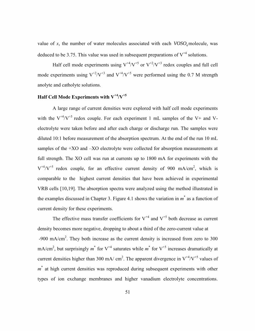
51
value of x, the number of water molecules associated with each 4VOSO molecule, was
deduced to be 3.75. This value was used in subsequent preparations of V+4
solutions.
Half cell mode experiments using V+4
/V+5
or V+2
/V+3
redox couples and full cell
mode experiments using V+2
/V+3
and V+4
/V+5
were performed using the 0.7 M strength
anolyte and catholyte solutions.
Half Cell Mode Experiments with V+4
/V+5
A large range of current densities were explored with half cell mode experiments
with the V+4
/V+5
redox couple. For each experiment 1 mL samples of the V+ and V-
electrolyte were taken before and after each charge or discharge run. The samples were
diluted 10:1 before measurement of the absorption spectrum. At the end of the run 10 mL
samples of the +XO and –XO electrolyte were collected for absorption measurements at
full strength. The XO cell was run at currents up to 1800 mA for experiments with the
V+4
/V+5
redox couple, for an effective current density of 900 mA/cm2, which is
comparable to the highest current densities that have been achieved in experimental
VRB cells [10,19]. The absorption spectra were analyzed using the method illustrated in
the examples discussed in Chapter 3. Figure 4.1 shows the variation in m* as a function of
current density for these experiments.
The effective mass transfer coefficients for V+4
and V+5
both decrease as current
density becomes more negative, dropping to about a third of the zero-current value at
-900 mA/cm2. They both increase as the current density is increased from zero to 300
mA/cm2, but surprisingly m
* for V
+4 saturates while m
* for V
+5 increases dramatically at
current densities higher than 300 mA/ cm2. The apparent divergence in V
+4/V
+5 values of
m* at high current densities was reproduced during subsequent experiments with other
types of ion exchange membranes and higher vanadium electrolyte concentrations.

52
Reasons for this behavior and the results of additional experiments to determine if the
transport difference was real or an artifact of the measurement technique will be
discussed in later sections.
Figure 4.1 V+4
and V+5
m* vs current density, N212 Membrane 0.7 M V concentration,
Half cell mode.
Half Cell and Full Cell Experiments with V+2
/V+3
A limited number of experiments with the V+2
/V+3
redox couple were performed
with the N212 membrane and the 0.7 M V electrolytes. Complications due to the
sensitivity of V+2
to oxidation from atmospheric oxygen limited the amount of data
collected using the V+2
/V+3
couple; as such, half cell and full cell experiments were
conducted at current densities up to 600 mA/cm2. In addition to purging of the V
+2/V
+3
reservoirs with inert gas, the sulfuric acid used in the XO reservoirs needed to be de-
oxygenated in order to preserve any V+2
collected during experiments. Oxidation of V+2
by dissolved oxygen leads to an underestimation of m*
for V+2
and overestimation of m*
for V+3
in a given experiment. Figure 4.2 shows m* as a function of current density for

53
V+2
and V+3
for both half cell and full cell mode experiments. The large amount of scatter
in the data is partly due to oxidation of V+2
to V+3
after collection.
Figure 4.2 V+2
and V+3
m* vs current density, N212 Membrane 0.7 M V concentration.
Half cell (‘V2V3’) and full cell (‘V2V3V4V5’) mode experiments.
Combined V+2
/V+3
and V+4
/V+5
Mass Transfer Coefficients
Since un-intended oxidation of V+2
artificially suppressed m* for V+2
and
enhanced m* for V+3
, the calculation of a combined V+2
/V+3
m* by combining the
measured concentrations of V+2
and V+3
has the potential to reduced the scatter in the
measurements. The formula used to calculate the combined mass transfer coefficient for
V+2
and V+3
transport between V- and –XO is:
2 3
2 3
2 3
*
/
( )
( )
XO XO
V V
V V V V
V V
Q c cm
AT c c
(4.1)
Figure 4.3 shows that the combined V+2
/V+3
m* varies linearly with current density, in
agreement with the prediction of the simple model result given by Equation (3.6), and the
amount of scatter in the data is less than that observed in Figure 4.2.

54
Figure 4.3 Combined V+2
/V+3
mass transport coefficient vs current density.
In the same way that un-intended oxidation of V+2
by dissolved oxygen affected
V+2
and V+3
mass transport calculations, un-intended side reactions were thought to be
present during higher current experiments with the V+4
/V+5
redox couple. The saturation
of the mass transport coefficient for V+4
for current densities greater than 300 mA/cm2, as
seen in Figure 4.1, implies that oxidation of V+4
to V+5
occurred after it had been
collected in the +XO reservoir. A combined V+4
/V+5
mass transport coefficient can be
defined using a formula analogous to Equation (4.1), and the results of that calculation
are shown in Figure 4.4. The combined mass transport coefficient for V+4
/V+5
increases
linearly for current densities greater than zero, consistent with Equation (3.6). The
combined V+4
/V+5
mass transport coefficient approaches a limiting value as current
densities become more negative.
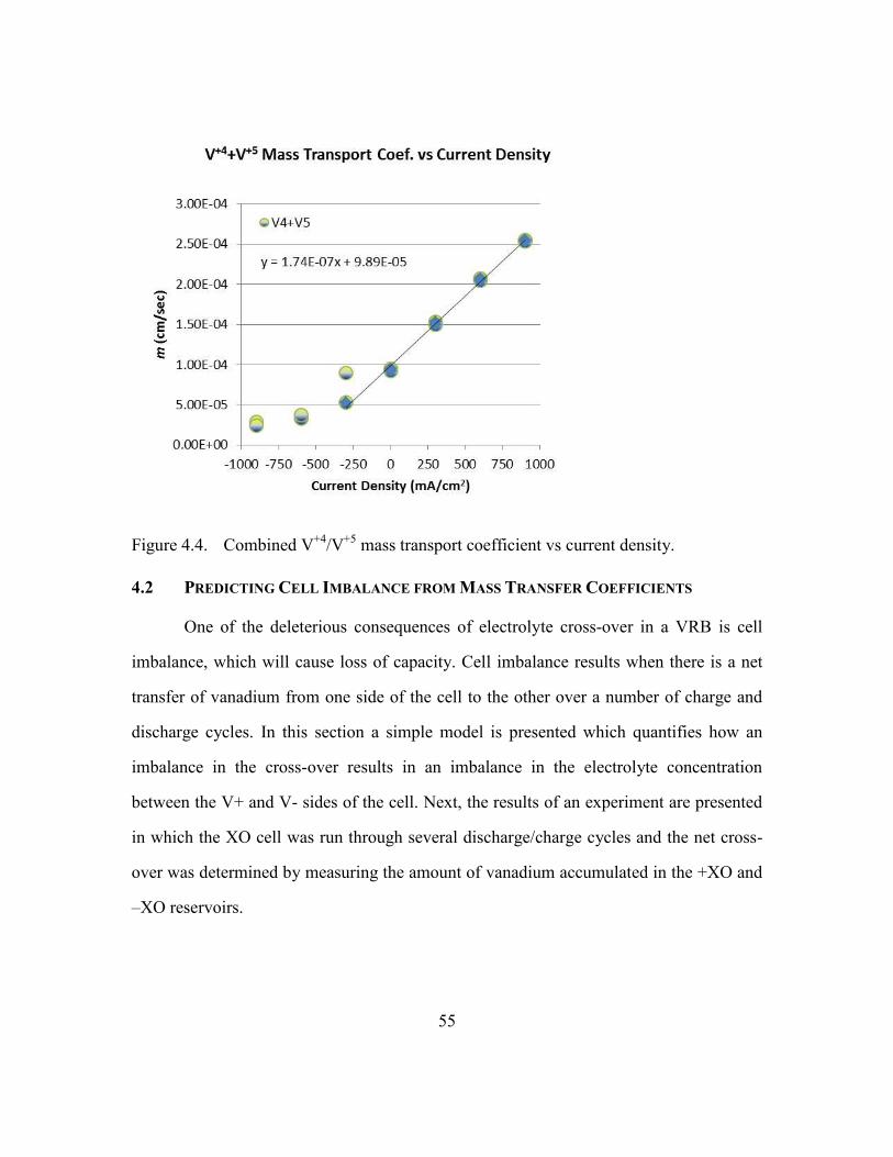
55
Figure 4.4. Combined V+4
/V+5
mass transport coefficient vs current density.
4.2 PREDICTING CELL IMBALANCE FROM MASS TRANSFER COEFFICIENTS
One of the deleterious consequences of electrolyte cross-over in a VRB is cell
imbalance, which will cause loss of capacity. Cell imbalance results when there is a net
transfer of vanadium from one side of the cell to the other over a number of charge and
discharge cycles. In this section a simple model is presented which quantifies how an
imbalance in the cross-over results in an imbalance in the electrolyte concentration
between the V+ and V- sides of the cell. Next, the results of an experiment are presented
in which the XO cell was run through several discharge/charge cycles and the net cross-
over was determined by measuring the amount of vanadium accumulated in the +XO and
–XO reservoirs.
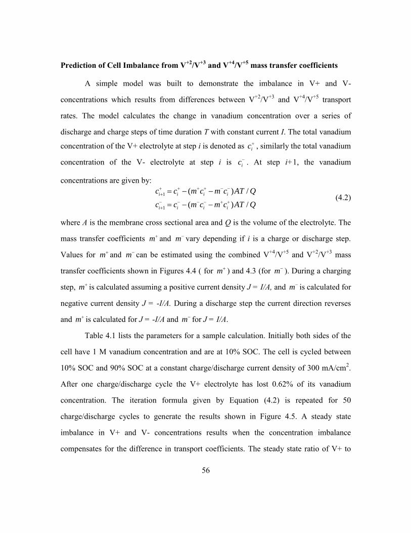
56
Prediction of Cell Imbalance from V+2
/V+3
and V+4
/V+5
mass transfer coefficients
A simple model was built to demonstrate the imbalance in V+ and V-
concentrations which results from differences between V+2
/V+3
and V+4
/V+5
transport
rates. The model calculates the change in vanadium concentration over a series of
discharge and charge steps of time duration T with constant current I. The total vanadium
concentration of the V+ electrolyte at step i is denoted as ic , similarly the total vanadium
concentration of the V- electrolyte at step i is ic . At step i+1, the vanadium
concentrations are given by:
1
1
( ) /
( ) /
i i i i
i i i i
c c m c m c AT Q
c c m c m c AT Q
(4.2)
where A is the membrane cross sectional area and Q is the volume of the electrolyte. The
mass transfer coefficients m and m vary depending if i is a charge or discharge step.
Values for m and m can be estimated using the combined V+4
/V+5
and V+2
/V+3
mass
transfer coefficients shown in Figures 4.4 ( for m ) and 4.3 (for m ). During a charging
step, m is calculated assuming a positive current density J = I/A, and m is calculated for
negative current density J = -I/A. During a discharge step the current direction reverses
and m is calculated for J = -I/A and m for J = I/A.
Table 4.1 lists the parameters for a sample calculation. Initially both sides of the
cell have 1 M vanadium concentration and are at 10% SOC. The cell is cycled between
10% SOC and 90% SOC at a constant charge/discharge current density of 300 mA/cm2.
After one charge/discharge cycle the V+ electrolyte has lost 0.62% of its vanadium
concentration. The iteration formula given by Equation (4.2) is repeated for 50
charge/discharge cycles to generate the results shown in Figure 4.5. A steady state
imbalance in V+ and V- concentrations results when the concentration imbalance
compensates for the difference in transport coefficients. The steady state ratio of V+ to

57
V- total vanadium concentrations can be shown to be equal to the inverse ratio of the
sum of the mass transfer coefficients during charge and discharge:
Chg DChgSS
SS Chg DChg
m mc
c m m
(4.3)
In the example shown in Figure 4.5, the V+ side of the cell increases in concentration and
the V- side decreases in concentration until the flux rates, integrated over a
charge/discharge cycle, balance. This simple model does not account for the self
discharge reactions listed in Table 1.1 that occur when the vanadium ions cross-over to
the other side of the cell. Much more detailed models of cross-over effects on cell
capacity have been produced by Knehr [16] and Tang [4]. These models take into
account side reactions and water transport, as well as treating all four vanadium species
separately, but both predict the establishment of a steady state imbalance when side
reactions are not significant.
Table 4.1 Parameters for Electrolyte Imbalance Model.
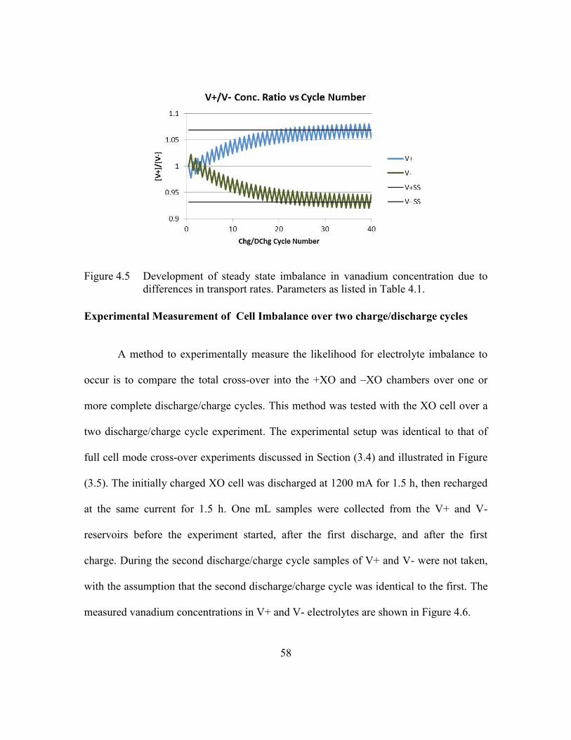
58
Figure 4.5 Development of steady state imbalance in vanadium concentration due to
differences in transport rates. Parameters as listed in Table 4.1.
Experimental Measurement of Cell Imbalance over two charge/discharge cycles
A method to experimentally measure the likelihood for electrolyte imbalance to
occur is to compare the total cross-over into the +XO and –XO chambers over one or
more complete discharge/charge cycles. This method was tested with the XO cell over a
two discharge/charge cycle experiment. The experimental setup was identical to that of
full cell mode cross-over experiments discussed in Section (3.4) and illustrated in Figure
(3.5). The initially charged XO cell was discharged at 1200 mA for 1.5 h, then recharged
at the same current for 1.5 h. One mL samples were collected from the V+ and V-
reservoirs before the experiment started, after the first discharge, and after the first
charge. During the second discharge/charge cycle samples of V+ and V- were not taken,
with the assumption that the second discharge/charge cycle was identical to the first. The
measured vanadium concentrations in V+ and V- electrolytes are shown in Figure 4.6.
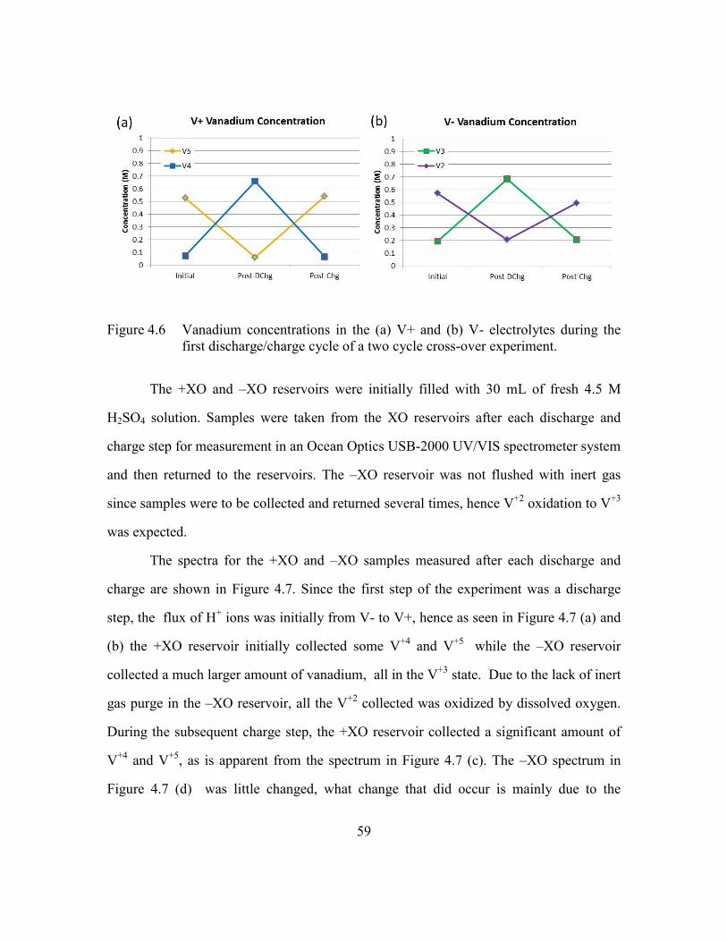
59
Figure 4.6 Vanadium concentrations in the (a) V+ and (b) V- electrolytes during the
first discharge/charge cycle of a two cycle cross-over experiment.
The +XO and –XO reservoirs were initially filled with 30 mL of fresh 4.5 M
H2SO4 solution. Samples were taken from the XO reservoirs after each discharge and
charge step for measurement in an Ocean Optics USB-2000 UV/VIS spectrometer system
and then returned to the reservoirs. The –XO reservoir was not flushed with inert gas
since samples were to be collected and returned several times, hence V+2
oxidation to V+3
was expected.
The spectra for the +XO and –XO samples measured after each discharge and
charge are shown in Figure 4.7. Since the first step of the experiment was a discharge
step, the flux of H+ ions was initially from V- to V+, hence as seen in Figure 4.7 (a) and
(b) the +XO reservoir initially collected some V+4
and V+5
while the –XO reservoir
collected a much larger amount of vanadium, all in the V+3
state. Due to the lack of inert
gas purge in the –XO reservoir, all the V+2
collected was oxidized by dissolved oxygen.
During the subsequent charge step, the +XO reservoir collected a significant amount of
V+4
and V+5
, as is apparent from the spectrum in Figure 4.7 (c). The –XO spectrum in
Figure 4.7 (d) was little changed, what change that did occur is mainly due to the

60
presence of V+4
in the –XO sample. The V+4
present is from cross-over of V+4
from the
+XO chamber and also from V+5
which crossed over and was immediately oxidized to
V+4
by V+3
in the –XO solution.
Figure 4.7 Spectra of samples from +XO in (a) (c) (e) and (g) and from –XO in (b) (d)
(f) and (g) measured after each step of a two cycle discharge/charge cross-
over experiment.

61
Figure 4.8 (a) Cumulative concentrations of vanadium collected in +XO and –XO
reservoirs during two cycle cross-over experiment. (b) Mass transfer
coefficients for V+ to +XO and V- to –XO averaged over two
discharge/charge cycles.
Figure 4.8 (a) shows the concentrations of the V+3
, V+4
, and V+5
in the +XO and
–XO reservoirs at the end of each step during the experiment. At the end of the second
discharge step (cycle number 1.5 in Figure 4.8), the +XO chamber has lost a small
amount of V+5
due to V+3
crossing over from the –XO chamber and reacting to form V+4
.
The concentration of V+3
in –XO has doubled due the influx of V+2
and V+3
into the –XO
chamber during the discharge step. At the end of the final charge step (cycle number 2 in
Figure 4.8) the concentration of V+4
and V+5
in the +XO reservoir has nearly doubled due
to the influx from the V+ chamber.
The concentration data in Figure 4.8 are used to calculate mass transfer constants for
cross-over from V- to –XO and V+ to +XO averaged over two discharge/charge cycles.
The results of these calculations are listed in Figure 4.8 (b). For this experiment the mass
transfer coefficients for transfer from V+ to +XO and V- to –XO are relatively close,

62
only differing about 5%, which means in steady state the average vanadium concentration
in a VRB cell would be about 5% less than on the V+ side compared to the V- side.
4.3 CROSS-OVER EXPERIMENTS WITH 1.5 M SOLUTIONS
Subsequent experiments with the XO cell were carried out with higher
concentration solutions of the vanadium anolyte and catholyte. Solutions were prepared
with 1.5 M vanadium concentration and 3.5 M H2SO4 concentration. Due to the higher
concentration of the vanadium in the V+ and V- chambers of the cell, samples taken for
spectroscopic analysis from these parts of the cell were diluted 20:1 before performing
absorption spectrometry analysis.
Membrane comparison experiments
A series of experiments were undertaken to compare the cross-over performance
of three different ion exchange membranes: Nafion N212, Nafion N117, and Fumatech
FX-7050. The Nafion membranes differ primarily in thickness, with N212 being 50 m
thick and N117 180 m thick. The Fumatech FX-7050 membrane is a per-fluorosulfonic
acid cation exchange membrane, nominally 50 m thick. Compared to the Nafion
membrane, the Fumatech membrane has better dimensional stability, with very little
swelling when wetted, and is more robust than equivalent thickness Nafion membranes.
The XO cell was run in half cell mode with the V+4
/V+5
redox couple. For all the
experiments run, the center membrane separating the +XO from the –XO chamber was
Nafion N117. The first set of experiments with 1.5 M concentration solutions were done
with N212 membranes separating the XO chambers from the neighboring V+/V-
chambers. N117 membranes were used in the second set of experiments, followed by a
third set with FX-7050 membranes.
63
N212 Membrane Experiments with 1.5 M V solutions
Figure 4.9 V+4
and V+5
m* vs current density, N212 Membrane 1.5 M V concentration,
Half cell mode.
Figure 4.9 shows the measured mass transport coefficient m* for V
+5 and V
+4 as a
function of current density for N212 experiments with 1.5 M total vanadium
concentration. The mass transport coefficient for V+5 rises much faster than V+4 for
current densities in excess of 450 mA/cm2, similar to what was observed in Figure 4.1 at
lower concentrations. Unexpectedly, the mass transport coefficients for the 1.5 M
concentration experiments are much less than those measured at 0.7 M concentrations. A
possible reason for the discrepancy is osmotic pressure differences present during the
lower concentration experiments driving convective flows. More care was taken to match
the sulfate concentration of the V+ and V- solutions to the sulfuric acid solutions used in
the +XO and –XO chambers during the higher concentration experiments. A set of
experiments in which sulfate concentration was deliberately mismatched was performed
later and the results will be discussed in a later chapter of this thesis. Those experiments

64
did show that sulfate concentration mismatch across an ion exchange membrane greatly
affects the amount of vanadium transport.
N117 Membrane Experiments with 1.5 M V solutions
Figure 4.10 shows the measured mass transport coefficient m* for V
+5 and V
+4 as
a function of current density for N117 experiments with 1.5 M total vanadium
concentration. The effect of the thicker membrane was apparent only for current densities
less than 450 mA/cm2, where the N117 transport coefficients were about a factor of two
less than those for N212. Cross-over rates at high current densities much more important
for determining net cross over than those at very negative current densities, so there
appears to be little advantage to using the thicker N117 membrane to mitigate cross over
effects.
Figure 4.10 V+4
and V+5
m* vs current density, N117 Membrane, 1.5 M V
concentration. Half cell mode.

65
FX-7050 Membrane Experiments with 1.5 M V solutions
Figure 4.11 shows the measured mass transport coefficient m* for V
+5 and V
+4 as
a function of current density for experiments with FX-7050 membranes with 1.5 M total
vanadium concentration. The effect of the Fumatech FX-7050 membrane is profound,
mass transport coefficients for V+4
and V+5
are reduced by a factor of three or more
compared to either Nafion membrane for all current densities tested. However, it was
noted that higher voltage was required to drive the equivalent current through the cell
when the FX-7050 membranes were in place, which indicates that the conductivity of the
Fumatech membrane was lower than that of the Nafion membranes. Quantitative
measurements of the difference in conductivity were not attempted due to corrosion on
the external clips connecting the cell to the battery test equipment causing variable
contact resistance run to run.
Figure 4.11 V+4
and V+5
m* vs current density, FX-7050 Membrane, 1.5 M V
concentration. Half cell mode

66
Direct Comparison of N212, N117, and FX-70450 Combined V+4
/ V+5
Transport
Coefficients
Figure 4.12 shows the combined V+4
/V+5
mass transfer coefficient for all three
types of membranes on the same scale. Figure 4.12 (a) shows the entire range of current
densities while (b) shows the range from -1000 mA/cm2 to 0 mA/cm
2. The difference
between the thicker (N117) and thinner (N212) Nafion membranes is apparent only at
current densities less than 450 mA/cm2. Figure 4.12 (b) shows in greater detail the
differences in cross-over for zero and negative current densities. Differences between the
two thickness of Nafion are readily apparent for negative current densities. Figure 4.12
(b) also shows the extremely low amount of cross-over for the Fumatech FX-7050
membranes at zero and negative current densities, about a factor of five less than N117
and more than a factor of ten less than N212. At the peak positive current densities cross-
over for FX-7050 is a factor of three less than that of the Nafion membranes.
Figure 4.12 (a) Combined V+4
and V+5
transport coefficient vs current density for N212,
N117, and FX-7050 Membranes -1000 to 1000 mA/cm2 (b) -1000 to 0
mA/cm2 x-axis.

67
4.4 EVIDENCE OF OXIDATION OF V+4
TO V+5
IN XO CELL
As reported in earlier sections of this thesis, the mass transfer coefficient m* for
V+4
appears to saturate for current densities 450 mA/cm2, while m
* for V
+5 increases
rapidly. At current densities below this value m* for V
+4 and V
+5 track together. One
possible explanation for this observation is that the V+4
collected in the +XO electrolyte
is being oxidized to V+5
. The +XO and –XO chambers of the XO cell are both filled with
carbon felt electrodes, and redox reactions could occur in the cross-over chambers if there
is a source or sink of electrons. When considering the oxidation of V+4
to V+5
in the +XO
chamber when the current density is positive (ie H+ flux flowing from V+ through the ion
exchange membrane to +XO), if there is sufficient membrane electronic conductivity
electrons could flow from the +XO porous electrode through the ion exchange membrane
to the V+ porous electrode and then into current collector. In this way V+4
in the +XO
electrolyte could be oxidized to V+5.
. Figure 4.13 (b) illustrates the current pathway for
this reaction.
Figure 4.13 (a) XO electrode without leakage path cannot support V+4
oxidation. (b)
Leakage path through membrane allows V+4
oxidation reaction to occur.

68
Cross-over Experiments with Vanadium solutions in the +XO reservoir
Figure 4.14 Experimental configuration with V electrolyte (V+4
this illustration) in +XO
reservoir and sulfuric acid in -XO reservoir. Experiments conducted with
V+5
and V+4
in +XO.
A new experimental arrangement was devised to try to prevent the occurrence of
the situation depicted in Figure 4.13 (b). Figure 4.14 shows the configuration used for a
series of experiments in which one of the XO reservoir was filled with a solution of either
V+4
or V+5
and the other reservoir was filled with sulfuric acid. The V+ reservoir was
filled with the usual V+5
/V+4
mixture and the V- reservoir was filled with V+2
/V+3
mixture. When the cell was being charged, V+4
oxidation occurred in the V+ chamber and
V+3
reduction occurred in the V- chamber. A flux of H+ flowed from V+ through the XO
chambers and into the V- chamber.
The composition of the vanadium solution in the +XO electrolyte was largely
unchanged throughout the experiment, while the –XO electrolyte collected V+4
which
crossed over from the +XO electrolyte due to diffusion and migration. The possibility of
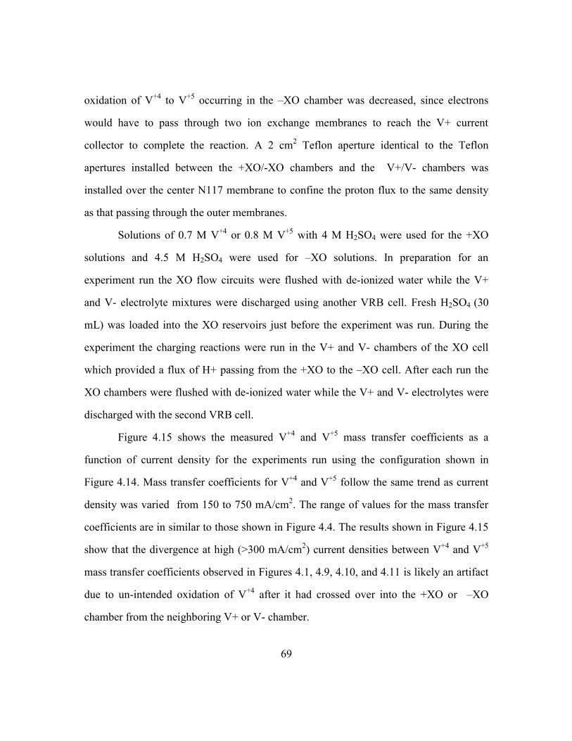
69
oxidation of V+4
to V+5
occurring in the –XO chamber was decreased, since electrons
would have to pass through two ion exchange membranes to reach the V+ current
collector to complete the reaction. A 2 cm2 Teflon aperture identical to the Teflon
apertures installed between the +XO/-XO chambers and the V+/V- chambers was
installed over the center N117 membrane to confine the proton flux to the same density
as that passing through the outer membranes.
Solutions of 0.7 M V+4
or 0.8 M V+5
with 4 M H2SO4 were used for the +XO
solutions and 4.5 M H2SO4 were used for –XO solutions. In preparation for an
experiment run the XO flow circuits were flushed with de-ionized water while the V+
and V- electrolyte mixtures were discharged using another VRB cell. Fresh H2SO4 (30
mL) was loaded into the XO reservoirs just before the experiment was run. During the
experiment the charging reactions were run in the V+ and V- chambers of the XO cell
which provided a flux of H+ passing from the +XO to the –XO cell. After each run the
XO chambers were flushed with de-ionized water while the V+ and V- electrolytes were
discharged with the second VRB cell.
Figure 4.15 shows the measured V+4
and V+5
mass transfer coefficients as a
function of current density for the experiments run using the configuration shown in
Figure 4.14. Mass transfer coefficients for V+4
and V+5
follow the same trend as current
density was varied from 150 to 750 mA/cm2. The range of values for the mass transfer
coefficients are in similar to those shown in Figure 4.4. The results shown in Figure 4.15
show that the divergence at high (>300 mA/cm2) current densities between V
+4 and V
+5
mass transfer coefficients observed in Figures 4.1, 4.9, 4.10, and 4.11 is likely an artifact
due to un-intended oxidation of V+4
after it had crossed over into the +XO or –XO
chamber from the neighboring V+ or V- chamber.
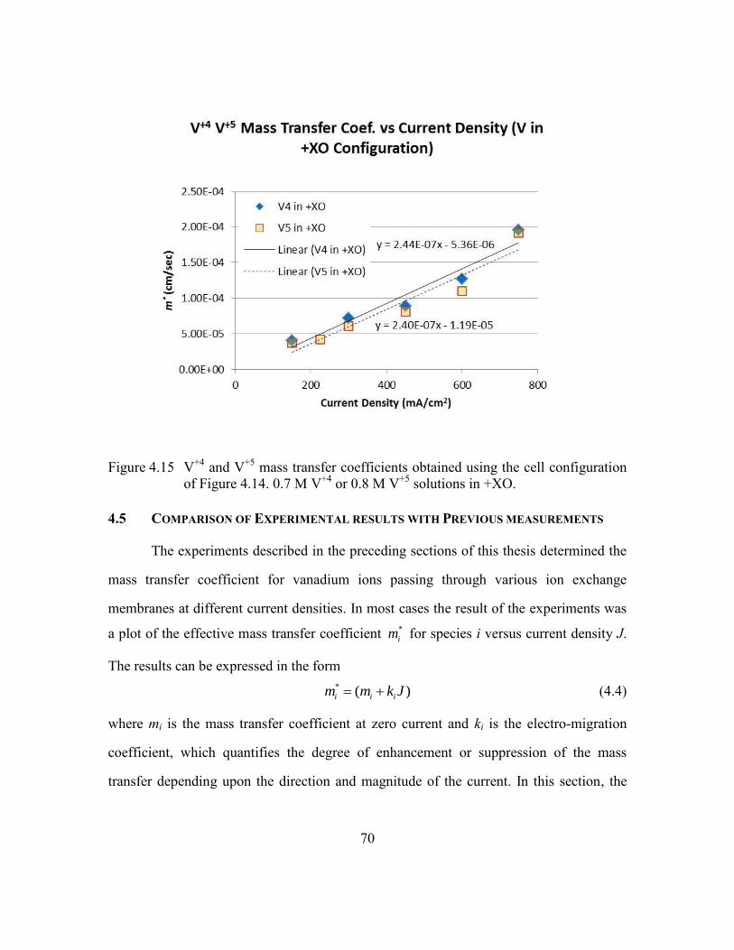
70
Figure 4.15 V+4
and V+5
mass transfer coefficients obtained using the cell configuration
of Figure 4.14. 0.7 M V+4
or 0.8 M V+5
solutions in +XO.
4.5 COMPARISON OF EXPERIMENTAL RESULTS WITH PREVIOUS MEASUREMENTS
The experiments described in the preceding sections of this thesis determined the
mass transfer coefficient for vanadium ions passing through various ion exchange
membranes at different current densities. In most cases the result of the experiments was
a plot of the effective mass transfer coefficient *
im for species i versus current density J.
The results can be expressed in the form
* ( )i i im m k J (4.4)
where mi is the mass transfer coefficient at zero current and ki is the electro-migration
coefficient, which quantifies the degree of enhancement or suppression of the mass
transfer depending upon the direction and magnitude of the current. In this section, the

71
values of mi and ki determined from the experiments with the XO cell will be compared
against results reported in the literature.
Table 4.2 lists the values of mi from References [8] and [9] (and as shown in
Tables 1.1 and 1.2) and the values of mi from the experimental results reported in sections
4.1,4.3, and 4.4 of this thesis. Also listed in Table 4.2 is the diffusion coefficient Di which
is calculated by multiplying the mass transfer coefficient mi by the membrane thickness l.
The diffusion coefficient is calculated to allow comparison of the experimental results
against the literature values, since three different thickness of Nafion membrane are
represented in the previous results and the experimental data. Figure 4.16 shows the
diffusion coefficient data listed in Table 4.2 plotted on a logarithmic scale.
Table 4.2 Comparison of mi and Di from previous results and experimental results.
The diffusion coefficient data shows the experimental results for the Nafion
membranes are larger than the results from References [8] and [9], by up to a factor of
ten. Such large differences could indicate a systematic problem in the measurements,
72
such as a leak which allowed electrolytes to bypass the membrane. However, cross-over
rates with the Fumatech FX-7050 membrane, obtained with exactly the same cell
configuration as the Nafion membrane results, were up to two orders of magnitude less.
This provides confidence that the transport measured was through the membranes tested
and there was no side channel for ionic transfer.
Figure 4.16 Diffusion coefficient data from Table 4.2.
The other parameter which can be obtained from the experiments is ki, the electro-
migration coefficient which describes the change in mass transport rate as function of the
applied current density. Experimental values of ki were obtained by applying linear
regression to the parts of the m*
vs J curves in which linear behavior was observed.
Because of issues with oxidation of V+2
and V+4
, the combined V+2
/V+3
or V+4
/V+5
mass
transport coefficient data were analyzed to determine ki from the experimental results
reported in Sections 4.1 and 4.3. There were no unintended oxidation reactions occurring
during the experiments reported in Section 4.4, so ki for V+4
and V+5
could be calculated
from the results of those experiments for each species separately. Table 4.3 gives a

73
compilation of the ki values obtained from the experiments described in this chapter and
the values of ki from Reference [9]. Aside from the value of ki for V+5
from Reference
[9], all of the ki values from the experiments and the literature are within a factor of 2.5 of
each other. It should be noted that the maximum current density used in the experiments
described in Reference [9] was 50 mA/cm2, while the maximum current densities for the
experiments in this thesis were in excess of 750 mA/cm2. The fact that the values of ki
from the literature and this thesis agree despite the huge difference in the range of current
densities investigated lends confidence in the results.
Table 4.3 Electro-migration coefficient ki from Reference [9] and the experiments
described in this thesis.
4.6 CONCLUSIONS FOR CURRENT DENSITY SCALING STUDY EXPERIMENTS
Common amongst all of the experimental results reported in this thesis is the
powerful effect current density magnitude and direction has on the cross-over rates of
vanadium ions through ion exchange membranes. Cross-over rates vary by up to several
decades in magnitude as current is varied from -900 to 900 mA/cm2, which are current
regimes relevant to the state of the art VRB cells being developed. Surprisingly, the
difference between thick and thin Nafion membranes (N117 vs N212) disappeared at the
highest current densities tested. The Fumatech FX-7050 membrane was the best

74
performing membrane from a cross-over perspective, with cross-over rates at large
positive current densities less than one third that of the Nafion membranes. At negative
current densities cross over rates for the Fumatech membrane were a factor of twenty less
than N212 and almost a factor of ten less than N117.
Electrolyte imbalance was shown to result when cross-over rates between the two
sides of a VRB are not equal. A simple model was constructed which demonstrates that
small (< 1%) electrolyte imbalances present over a single charge/discharge cycle will
grow over many cycles and can eventually lead to a steady state electrolyte imbalance
situation. A method to directly measure the net cross-over in the XO cell by running the
cell over several discharge/charge cycles was described and the results from an
experiment showed the feasibility of this method.
Comparison of results with low (~ 0.7 M) and high (~ 1.5 M) concentration
vanadium solutions with the same membrane (N212) showed a factor of two difference in
the measured cross-over rates, with the rate for the lower concentration being higher. A
possible cause for this discrepancy may be the presence of convective flows which
provide an additional transport mechanism for ions to move across a membrane. A set of
experiments will be described in the next chapter which quantifies the effect of
convective flows on vanadium cross-over.
The absolute value of the diffusion coefficient measured for Nafion membranes in
the experiments described in this thesis was approximately one order of magnitude higher
than those measured by other researchers. However, the diffusion coefficient for
Fumatech FX-7050 membrane material was two orders of magnitude less than the value
measured for Nafion membranes, which indicates that the experimental technique used in
this thesis was sound and the transport measured was through the membrane and leakage
around the membrane was not likely to have occurred. The experimentally determined
75
electro-migration coefficient for Nafion membranes measured in this thesis agreed with
the value reported in the literature within a factor of 2.5, despite the large difference in
current densities between the previous results and this thesis.

76
Chapter 5: Convective Flow Effects on Cross-over
5.1 CONVECTIVE FLOW EFFECTS ON MASS TRANSPORT
In addition to diffusion and migration, convective flow is an important effect to
consider when analyzing mass transport. The expression for the flux of species i taking
into account diffusion, electro-migration, and convection is:
i i i i i i iN D c z c cV (5.1)
Equation (5.1) differs from Equation (3.1) only in the addition of the convective term
icV , where V is the bulk fluid velocity. The addition of the convection term adds an
additional term to the expression for the effective mass transfer coefficient m*:
* ( )i i i m em m z k J kV (5.2)
In Equation (5.2) the factor k in the convective term is the partition coefficient which was
first introduced in Equation (3.6) and takes into account the drop in the vanadium
concentration across the membrane to electrolyte interface.
As mentioned at the conclusion of the previous chapter, an unresolved issue from
the experimental results is the discrepancy between measurements of m* obtained with
experiments with low (~ 0.7 M) and high (~ 1.5 M) concentration vanadium solutions
using the same membrane (Nafion N212). Convective flow effects provide a possible
explanation for this discrepancy. A set of experiments was designed to deliberately
introduce convective flow variations and to quantify their effect on vanadium cross-over.

77
5.2 CONVECTIVE FLOW/ VARIABLE SULFATE CONCENTRATION CROSS-OVER
EXPERIMENTS
Experiment Configuration
Convective flow variations were created by varying the difference in total ionic
strength across the membrane. The experimental arrangement for these experiments is
shown in Figure 5.1.
Figure 5.1 Experimental configuration for convective flow experiments.
This experimental configuration is similar to that described in section (4.3) of the
previous chapter, in which cross-over between the two XO chambers of the cell was
studied by flowing a solution of V+5
or V+4
on one side of the center N117 membrane
and sulfuric acid on the other side. In those experiments the strength of the sulfuric acid
solutions were adjusted so that the total sulfate concentrations on both sides of the center
membrane matched. In the experiments described in this chapter, the concentration of the
sulfuric acid in the –XO solution was reduced for some experimental runs to introduce an

78
osmotic pressure gradient across the center membrane and an accompanying bulk fluid
flow. The +XO reservoir was filled with 25 mL of 5 M H2SO4 while the –XO reservoir
was filled with 100 mL of a mixture of 0.5 M VOSO4 (i.e. V+4
) with 4.5 M, 3.25 M, or 2
M sulfuric acid. In this way a sulfate concentration difference of zero, 1.25, or 2.5 M was
imposed across the center N117 membrane. Fumatech FX-7050 membranes are used to
separate the +XO and –XO chambers from the V+ and V- chambers of the cell. The FX-
7050 membranes were found to have the lowest cross-over of the three membrane types
tested, and the use of these membranes insures that the cross-over from the –XO chamber
through the center N117 membrane is the dominant source of vanadium flowing into the
+XO chamber of the cell.
Fluid volume increases of several mL were noted in the +XO reservoir when a
2.5 M difference in sulfate concentration existed across the membrane during the
experiments. However, the reservoirs for the +XO and –XO pumping circuits were 25
mL graduated cylinders with a minimum graduation of 0.5 mL, so it was impossible to
make accurate measurements of the volume changes. Table 5.1 lists the measured volume
changes and calculated fluid flux rate for runs with a 2.5 M sulfate concentration
difference. Smaller (< 0.5 mL) volume differences were noted when the sulfate difference
was 1.25 M. The sulfate concentration difference was used as an independent variable
instead of the fluid flux when analyzing the results from the experiment, with the implicit
assumption that fluid flux is proportional to the sulfate concentration difference.
Figure 5.2 shows the measured effective mass transport coefficients for the
experiment runs. The x-axis label lists the sulfate concentration difference and the current
density for each run. The sulfate concentration had a large effect on the mass transfer
coefficients, with m* increased by more than a factor of three when a sulfate
concentration difference of 2.5 M was present across the membrane.

79
Table 5.1 Fluid volume increases and water flux for runs with 2.5 M sulfate
concentration difference.
Figure 5.2 Calculated Mass Transport Coefficients for the variable sulfate experiments.
Data Analysis using a Full Factorial Model
The results were analyzed using a full factorial model of the form given by
Equation (5.3) with linear variation in sulfate concentration difference 4SO and current
density eJ and an interaction term proportional to 4 * eSO J :
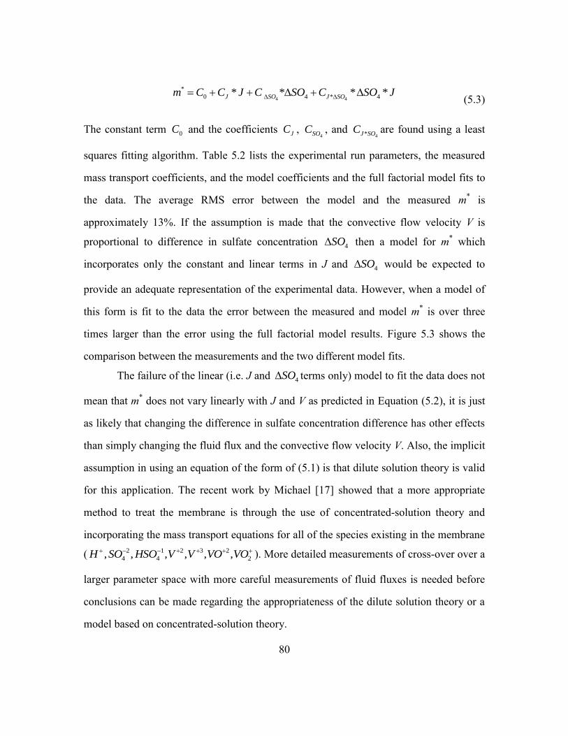
80
4 4
*
0 4 * 4* * * *J SO J SOm C C J C SO C SO J (5.3)
The constant term 0C and the coefficients JC , 4SOC , and
4*J SOC are found using a least
squares fitting algorithm. Table 5.2 lists the experimental run parameters, the measured
mass transport coefficients, and the model coefficients and the full factorial model fits to
the data. The average RMS error between the model and the measured m* is
approximately 13%. If the assumption is made that the convective flow velocity V is
proportional to difference in sulfate concentration 4SO then a model for m* which
incorporates only the constant and linear terms in J and 4SO would be expected to
provide an adequate representation of the experimental data. However, when a model of
this form is fit to the data the error between the measured and model m* is over three
times larger than the error using the full factorial model results. Figure 5.3 shows the
comparison between the measurements and the two different model fits.
The failure of the linear (i.e. J and 4SO terms only) model to fit the data does not
mean that m* does not vary linearly with J and V as predicted in Equation (5.2), it is just
as likely that changing the difference in sulfate concentration difference has other effects
than simply changing the fluid flux and the convective flow velocity V. Also, the implicit
assumption in using an equation of the form of (5.1) is that dilute solution theory is valid
for this application. The recent work by Michael [17] showed that a more appropriate
method to treat the membrane is through the use of concentrated-solution theory and
incorporating the mass transport equations for all of the species existing in the membrane
( 2 1 2 3 2
4 4 2, , , , , ,H SO HSO V V VO VO ). More detailed measurements of cross-over over a
larger parameter space with more careful measurements of fluid fluxes is needed before
conclusions can be made regarding the appropriateness of the dilute solution theory or a
model based on concentrated-solution theory.

81
Table 5.2 Experimental Conditions and Results for variable sulfate experiments.

82
Figure 5.3 Comparison of Full Factorial and Linear Model fits to measured mass
transport coefficient data.
5.3 COMPARISON OF VARIABLE SULFATE CONCENTRATION MODEL WITH RESULTS
FROM CURRENT SCALING EXPERIMENTS
The results of the variable sulfate experiment reported in the previous section
showed that mismatch in the sulfate concentration across the membrane can cause large
effects on the cross-over rates of vanadium. A 2.5 M mismatch in the sulfate
concentration caused an increase in the V+4
cross-over rate through Nafion N117 of over
a factor of three at zero and 600 mA/cm2 current density. The results of the variable
sulfate experiment were fit to a full factorial model which can be used to predict the mass
transport rate for V+4
through N117 as a function of current density and sulfate
concentration difference across the membrane. The full factorial model is used to
compare the V+4
mass transfer coefficients obtained with N212 membranes at low and
high vanadium concentrations.
83
Figure 5.4 compares the measured V+4
m* values for the different experiments
described in the previous chapter against the experimental results from variable sulfate
experiment at 600 mA/cm2 and the predictions of the full factorial model with different
sulfate concentrations. As noted earlier, the results for low (0.7 M) and high (1.5 M)
concentration experiments with N212 membranes differed considerably. The discrepancy
between the low and high concentration N212 data can explained using the results from
the variable sulfate experiment if a 2.5 M sulfate concentration difference existed during
the lower concentration experiments which added an additional source to the cross
membrane transport. This amount of sulfate concentration mismatch is larger than the
amount of error (~ 0.5 M) likely due to errors in solution preparation, so the reason for
the discrepancy between the different experiments is still unknown.
Figure 5.4 Comparison of V+4
m*
from different experiments (described in Chapter 4)
with results from full factorial model of variable sulfate experiment.
84
5.4 CONCLUSIONS FOR CONVECTIVE FLOW EFFECTS ON CROSS-OVER
The effect of varying convective flow velocity as well as current density was
tested in the experiment described in this chapter. The convective flow velocity was
found to vary monotonically with the sulfate concentration difference across the ion
exchange membrane. Cross-over rates at zero and 600 mA/cm2
current density were
observed to increase by more than a factor of three when a sulfate concentration
difference of 2.5 M was imposed across a Nafion N117 membrane. A full factorial model
with terms proportional to current density, sulfate concentration difference, and the
product of the two was found to best describe the experimental results. The results show
that convective flow effects have a large effect on the transport of vanadium through ion
exchange membranes and needed to be taken into account when running cross-over
experiments. However, the level of sulfate concentration mismatch needed to explain all
of the variation in the mass transfer coefficients measured during the various experiments
described in Chapter 4 of this thesis is larger than the likely variations that occurred
during the experiments.
85
Chapter 6: Conclusions and Recommendations for Future Work
6.1 CONCLUSIONS
Spectroscopic measurement of Vanadium electrolyte mixtures
The characteristic colors of the aqueous solutions containing V+2
, V+3
, V+4
and
V+5
had prompted many different groups to investigate the use of absorption
spectroscopy to determine the composition and concentration of vanadium ion mixtures
encountered in VRB work. However, problems with anomalous absorption which could
not be reconciled with Beer’s law had lead researchers to discount the usefulness of this
method for determining the composition of mixtures of V+4
and V+5
ions. In this thesis, it
was demonstrated that dilution of the solutions of vanadium ion mixtures was sufficient
to allow the spectroscopic analysis of any mixture of vanadium ions, as long as the final
concentration was less than 0.1 M. Methods to determine the composition and
concentration of vanadium ion mixtures using absorption data at three different
wavelengths were developed and applied in the analysis of the cross-over experiments
reported in this thesis.
Triple Membrane Cell
The most important product from this work was the development of the Triple
Membrane (or XO) cell for the study of electrolyte cross-over in a flow battery under
realistic operating conditions. The XO cell is a standard porous electrode VRB with two
additional chambers which connect the V+ and V- chambers of the cell. The additional
chambers, called the positive and negative cross over, or +XO and –XO chambers for
short, provide an ionic conduction path between the V+ and V- chambers of the VRB.
The +XO and –XO chambers contain sulfuric acid solution which maintains ionic
conduction across the cell as well as providing a medium for the collection and analysis
86
of electrolyte species which cross through the ion exchange membranes separating the
XO chambers from the V+ and V- chambers.
Scaling of Cross-over with Current Density
The XO cell was successfully operated as a VRB and clearly demonstrated the
powerful effect current density has on the transport of vanadium ions across an ion
exchange membrane. The numerous experiments which were performed with the XO cell
demonstrated that at current densities that have been achieved by leading edge research
groups, the contribution of electric field effects to electrolyte cross-over often far exceeds
that due to diffusion alone. At large positive current densities (up to 900 mA/cm2) cross-
over was increased by more than a factor of five (for N117) compared to the no current
case. At large negative current densities (as small as -900 mA/cm2) cross-over was
suppressed by up to an order of magnitude compared to diffusion alone.
The current density scaling experiments were extended to include the comparison
of three different ion exchange membranes: Nafion N212, N117, and Fumatech FX-7050.
In head to head experiments, the Fumatech membrane was found to have up to a factor of
three less cross-over at large positive current densities and an order of magnitude less
cross-over at large negative current densities compared to either Nafion membrane. The
difference between the two Nafion membranes was only apparent for current densities
less than 450 mA/cm2, at or above this level the cross-over of the thick (N117) and thin
(N212) Nafion membranes were the same.
Prediction of Electrolyte imbalance
A simple model was developed which demonstrated how differences in cross-over
rates between the V+ and V- sides of a VRB can lead to capacity loss due to the
development of an electrolyte imbalance situation. Since the cross-over rates have great
87
sensitivity to the direction and magnitude of the current flow through the cell, any model
which is used to predict capacity loss due to cross-over must incorporate the current
density effects in addition to diffusion effects. The use of the XO cell to measure the net
cross-over from V+ and V- chambers over multiple discharge and charge cycles was
demonstrated in an experiment over two full discharge/charge cycles. Samples of the
electrolyte from the +XO and –XO chambers of the XO cell were analyzed after each
step of the experiment and the net cross-over rate was determined. The direct
measurement of net cross-over by the XO cell over one or two cycles can allow the
prediction of an electrolyte imbalance condition which would take many (20 to 50 cycles
or more) to become apparent as a capacity loss in a conventional cell.
Demonstration of convective flow effects
The effect of osmotic pressure gradient driven convective flows on cross-over
was studied in an experiment in which a deliberate mismatch in sulfate levels was used to
modulate cross-over between the +XO and –XO chambers of the XO cell. Mismatches in
sulfate level of 2.5 M were shown to lead to measureable fluid transfer (assumed to be
water) during cross-over experiments. Cross-over rates with and without current density
were affected by the osmotic pressure gradient caused by the sulfate concentration
difference. The cross-over results were found to be best fit by a full factorial model which
included linear terms in current density and sulfate concentration difference and a non-
linear interaction term proportional to the product of the two. The interaction term is not
predicted by dilute solution theory, but the strictly speaking the membrane-electrolyte
system is best modeled with concentrated solution theory.
However, the differences in sulfate concentrations needed to explain the
difference in cross-over rates with N212 membranes at low and high vanadium
88
concentration are larger than those that were likely to have occurred during electrolyte
solution preparation. The results of the convective flow experiment do show the
importance of careful preparation of the vanadium solutions and in the specification of
the strength of the sulfuric acid solutions used to collect cross-over in the XO cell
experiments. The results also demonstrated a method to isolate changes in transport due
to convective flows from changes due to concentration gradients and electric field effects.
Oxidation of V+4
to V+5
during cross-over measurements
At moderately high current densities ( > 300 mA/cm2) the mass transport
coefficient for V+5
increased rapidly with current density while that of V+4
showed signs
of saturation. This effect was seen in current scaling experiments carried out with V+4
and
V+5
at both high and low concentrations and with all three membranes tested. A
mechanism was proposed in which leakage currents through the ion exchange membrane
separating the +XO from the V+ chambers of the XO cell allowed oxidation of V+4
collected in the +XO chamber to converted to V+5
. A series of experiments were run in
which solutions of either V+4
or V+5
were pumped through the +XO chamber, and cross-
over to the –XO chamber was studied as a function of current density. This experimental
configuration provided improved electrical isolation of the chamber of the cell which in
which V+4
or V+5
is collected, and in this manner oxidation of V+4
was reduced. The large
difference in the V+4
and V+5
mass transport coefficients at high current densities
disappeared with the new experimental configuration, which suggests that un-intended
oxidation of V+4
was present in the earlier experiments.

89
6.2 RECOMMENDATIONS FOR FUTURE WORK
Improvements in the VRB cell designs
All of the experimental VRB cells built for these experiments had problems with
leaking electrolytes. Part of the problem was found to the porous nature of the graphite
used to machine the current collectors of the VRB cells. Graphite was purchased from
Glemco Inc, which supplies graphite for use in the semiconductor industry. Graphite
parts used in semiconductor equipment are most often used in a vacuum environment,
and graphite is not typically used in parts in which a vacuum seal to atmosphere is made.
Consequently, the graphite parts used in the VRB cells which were wetted on one side
and exposed to the atmosphere on the other side showed signs of liquid penetration. The
other source of leakage was due to the design of the electrodes themselves. The sealing
surface of the electrodes is approximately 4 mm wide and the electrodes were recessed
into the PVC flange of the cell, making it difficult to verify the integrity of the electrode
to flange seal. Simplification of the design to incorporate planar electrodes with simple
flat gasket seals would eliminate the seal leakage problem. Elimination of leaking issues
would allow the cells to be used over longer duration experiments and over multiple
charge/discharge cycles, and for changes in electrolyte volume due to convective flow
effects to be more easily detected.
Membrane selection within the XO cell
The membrane comparison studies revealed that the Fumatech FX-7050
membrane had very low cross-over rates, both in the forward and backward current flow
directions, compared to the Nafion brand membranes. The Fumatech membrane is the
best choice for the membrane to separate the +XO and –XO chambers of the XO cell
when studying net cross-over between V+ and V- chambers, which is important for

90
predicting capacity loss due to electrolyte imbalance situtaions. The net cross-over
experiment discussed in section 4.2 of this thesis used a Nafion N117 membrane to
separate the +XO and the –XO chambers, and a measureable amount of vanadium was
exchanged between those two regions of the cell. The bulk of the cross-over that
contributed to the vanadium detected in the +XO and –XO electrolytes in those
experiments was from the adjacent V+ and V- chambers. However, the small amount of
vanadium exchanged between the XO chambers became more significant when the net
cross over rate was calculated since the net cross over involves the difference between
two comparably sized quantities (i.e. the V+ and V- cross-over rates).
Half Cell Mode Experiment Improvements
Many of the experiments were performed using the XO cell in the half cell mode,
in which one side of the cell runs a redox reaction in the oxidation direction and the other
side of the cell ran the same reaction in the opposite direction. Two separate reservoirs
were used in the experiments, and the duration of the experiment was limited by the
volume, concentration, and initial state of charge of the electrolytes stored in each
reservoir. Recently, researchers at United Technologies have shown that by using a single
electrolyte reservoir, a quasi-steady state half cell reaction can be maintained in a flow
battery cell [19]. Both sides of the battery use the same flow circuit, with the electrolyte
exiting one side of the cell immediately entering the other side of the cell. Reactants
which are consumed in the first reaction are immediately restored during the second
reaction. The use of the quasi-steady state half cell mode eliminates variations in the
electrolyte composition during the experiments which are presently accounted for by
averaging starting and ending compositions and assuming linear behavior during the

91
experiment. Also, experiments can be run indefinitely, which is useful when cross-over
rates are very low.
Additional Experiments on Convective Flow Effects
The experiment described in Chapter 5 provides a method to produce convective
flow effects through the variation in the sulfate concentration difference between the
different electrolyte solutions. Electrolyte volume differences which can used to deduce
convective flow velocity variations were observed and could be related to the sulfate
concentration differences, but the type of electrolyte reservoir used in the experiments
did not provide sufficient resolution for volume change measurements to be made
accurately. Redesign of the electrolyte reservoirs to improve the ability to measure
electrolyte volume differences is needed.
The results of the Chapter 5 experiment were best fit with an empirical model
with linear terms in current density and sulfate concentration difference, and a nonlinear
term proportional to the product of current density and sulfate difference. The original
experiments only investigated five combinations of current density and sulfate
concentration difference, more experiments to explore the two dimensional parameter
space are needed to explore in greater detail the non-linear nature of the transport.
Experiments with other species other than V+4
are also needed to obtain data important
for understanding the importance of convective flow in cross-over for all of the species
important for VRB’s.
Experiments with Advanced VRB Cell Designs
The experiments described in this thesis were performed using a simple flow
battery cell design utilizing carbon felt electrodes and capable of modest current densities
(~ 250 mA/cm2). Higher current densities for testing membrane cross-over were achieved
92
by the use of current defining apertures and by driving the cell with external power
supplies (ie. potentiostats) during charging and discharge cycles with little regard to
voltage or energy efficiency. The leading edge VRB cells optimized for peak power
density are able to efficiently operate at current densities up to 1000 mA/cm2 [10,20]. A
logical extension of the work reported in this thesis is to modify a high performance VRB
cell by adding the additional membranes and porous electrode chambers to directly
measure cross-over. The additional membranes, porous electrodes, and electrolyte inlet
and outlets that comprise the additional chambers of the XO cell can be fit within two 3
Mm thick Viton gaskets which can be sandwiched between the positive and negative half
cells of current experimental VRB cells. In this way virtually any type of VRB cell can
be made into an XO cell with dedicated chambers to collect cross-over from the positive
and negative half cells.
Investigation of other Variables affecting Cross-over
The relatively large discrepancy (~ factor of 10) between the Nafion zero current
diffusion coefficients reported in the literature and the results found in this work as well
as the large variation seen in the literature demonstrates that all of the variables affecting
cross-over through flow battery membranes are not known. One possible variable to
explore in future work is the compression of the porous electrodes against the
membranes. Various changes that were made to the graphite electrode gaskets in an
attempt to control electrolyte leakage issues during this work caused variation in the
degree of compression that the porous electrodes were subjected to. Also, many of the
dialysis cell experiments reported in the literature were made with free standing
membranes without any porous electrodes in contact with the membranes.

93
It is possible that the Nafion membranes that were used in the experiments
described in this thesis were subjected to extreme conditions compared to the
experiments described in the literature. Operation at extremely high current densities with
large voltages and at nearly 100% SOC produces conditions which are known to damage
graphite porous electrodes and current collectors. Wear patterns corresponding to the
position of the 2 cm2 Teflon aperture were observable in the graphite electrodes used in
the XO cell experiments. Microscopic examination of the Nafion membranes which have
been subjected to extreme conditions might reveal flaws which could lead to enhanced
transport. The use of improved experimental techniques such as the quasi-steady state
half cell mode and closer attention to osmotic pressure gradient effects would reduce
other sources of variation and improve the chances of identifying other variables
influencing electrolyte cross-over.
6.3 CLOSING REMARKS
The most important result of this thesis was not the actual experimental results,
but the development of a method to directly measure electrolyte cross-over under realistic
operating conditions using the triple membrane (XO) cell. The XO cell geometry, with
the additional chambers between the half cells of a standard RFB, successfully
demonstrated that cross-over from each side of the cell could be collected with minimal
cross-talk between the two sides of the cell, and in the case of vanadium can easily be
diagnosed with simple spectroscopic absorption measurements. The results of the
experiments clearly showed the importance of current driven transport when considering
cross-over of electrolytes in a VRB cell, and show how capacity loss can be predicted
from the results of cross-over measurements over just a few charge/discharge cycles.

94
Appendix: Compilation of Experimental Run Data
CHAPTER 4 EXPERIMENTS
Table A1 Low Concentration (0.7 M) V+2/
V+3
and V+4/
V+5
N212 Cross-over Data
(Figures 4.1, 4.2, 4.3, 4.4).
Date Membrane Species Initial_C Final_C Dilution Avg_ConcXO_Conc Time Vol (CC) J_Dens Mass Trans Diff_C Exp_Type Combined m
8/3/2012 N212 V5 0.004035 0.027261 10 0.1565 0.0047 7200 53 0 1.10E-04 5.51E-07 V4V5 9.51E-05
8/3/2012 N212 V4 0.035062 0.007561 10 0.2131 0.0049 7200 53 0 8.40E-05 4.20E-07 V4V5
8/3/2012 N212 V5 0.026316 0.001157 10 0.1374 0.0040 7200 53 0 1.08E-04 5.38E-07 V4V5 9.19E-05
8/3/2012 N212 V4 0.009572 0.0377 10 0.2364 0.0053 7200 53 0 8.27E-05 4.14E-07 V4V5
8/2/2012 N212 V5 0.004234 0.029676 10 0.1696 0.0077 7200 53 300 1.67E-04 8.36E-07 V4V5 1.53E-04
8/2/2012 N212 V4 0.034768 0.007705 10 0.2124 0.0082 7200 53 300 1.41E-04 7.07E-07 V4V5
8/2/2012 N212 V5 0.027377 0.001992 10 0.1468 0.0040 7200 53 -300 1.01E-04 5.03E-07 V4V5 8.95E-05
8/2/2012 N212 V4 0.010074 0.037265 10 0.2367 0.0053 7200 53 -300 8.26E-05 4.13E-07 V4V5
8/3/2012 N212 V5 0.027943 0.004049 10 0.1600 0.0033 7200 53 -300 7.50E-05 3.75E-07 V4V5 5.33E-05
8/3/2012 N212 V4 0.007327 0.035306 10 0.2132 0.0021 7200 53 -300 3.70E-05 1.85E-07 V4V5
8/3/2012 N212 V5 0.002057 0.02891 10 0.1548 0.0076 7200 53 300 1.81E-04 9.07E-07 V4V5 1.50E-04
8/3/2012 N212 V4 0.037273 0.008238 10 0.2276 0.0079 7200 53 300 1.28E-04 6.40E-07 V4V5
8/7/2012 N212 V5 0.003093 0.030102 10 0.1660 0.0104 3600 33 600 2.88E-04 1.44E-06 V4V5 2.07E-04
8/7/2012 N212 V4 0.035623 0.008329 10 0.2198 0.0070 3600 33 600 1.46E-04 7.32E-07 V4V5
8/7/2012 N212 V5 0.028113 0.000107 10 0.1411 0.0008 3600 33 -600 2.70E-05 1.35E-07 V4V5 3.33E-05
8/7/2012 N212 V4 0.009474 0.038566 10 0.2402 0.0019 3600 33 -600 3.70E-05 1.85E-07 V4V5
8/7/2012 N212 V5 0.030102 0.002754 10 0.1643 0.0014 3600 33 -600 3.91E-05 1.96E-07 V4V5 3.72E-05
8/7/2012 N212 V4 0.008329 0.036422 10 0.2238 0.0018 3600 33 -600 3.59E-05 1.79E-07 V4V5
8/7/2012 N212 V5 0.000107 0.028634 10 0.1437 0.0108 3600 33 600 3.44E-04 1.72E-06 V4V5 2.04E-04
8/7/2012 N212 V4 0.038566 0.008029 10 0.2330 0.0060 3600 33 600 1.18E-04 5.91E-07 V4V5
8/10/2012 N212 V5 0.032027 0.001775 10 0.1690 0.0007 3000 33 -900 2.14E-05 1.07E-07 V4V5 2.90E-05
8/10/2012 N212 V4 0.009973 0.041687 10 0.2583 0.0016 3000 33 -900 3.39E-05 1.69E-07 V4V5
8/10/2012 N212 V5 0.003126 0.03248 10 0.1780 0.0138 3000 33 900 4.25E-04 2.12E-06 V4V5 2.55E-04
8/10/2012 N212 V4 0.040126 0.00831 10 0.2422 0.0057 3000 33 900 1.30E-04 6.52E-07 V4V5
8/10/2012 N212 V5 0.001775 0.032214 10 0.1699 0.0139 3000 33 900 4.48E-04 2.24E-06 V4V5 2.53E-04
8/10/2012 N212 V4 0.041687 0.008975 10 0.2533 0.0056 3000 33 900 1.23E-04 6.13E-07 V4V5
8/10/2012 N212 V5 0.03248 0.002632 10 0.1756 0.0006 3000 33 -900 2.02E-05 1.01E-07 V4V5 2.40E-05
8/10/2012 N212 V4 0.00831 0.040221 10 0.2427 0.0012 3000 33 -900 2.68E-05 1.34E-07 V4V5
8/21/2012 N212 V5 0.034677 0.034677 10 0.3468 0.0047 3600 33 0 6.28E-05 3.14E-07 V2V3V4V5 6.34E-05
8/21/2012 N212 V4 0.01985 0.01985 10 0.1985 0.0028 3600 33 0 6.44E-05 3.22E-07 V2V3V4V5
8/22/2012 N212 V5 0.035261 0.035261 10 0.3526 0.0042 3600 33 0 5.44E-05 2.72E-07 V2V3V4V5 5.78E-05
8/22/2012 N212 V4 0.020368 0.020368 10 0.2037 0.0028 3600 33 0 6.38E-05 3.19E-07 V2V3V4V5
8/22/2012 N212 V3 0.013147 0.013147 10 0.1315 0.0017 3600 33 0 5.92E-05 2.96E-07 V2V3V4V5 7.68E-05
8/22/2012 N212 V2 0.034532 0.034532 10 0.3453 0.0063 3600 33 0 8.35E-05 4.18E-07 V2V3V4V5
8/23/2012 N212 V5 0.038328 0.00672 10 0.2252 0.0005 6000 33 -600 6.41E-06 3.20E-08 V2V3V4V5 1.82E-05
8/23/2012 N212 V4 0.012891 0.047479 10 0.3019 0.0030 6000 33 -600 2.70E-05 1.35E-07 V2V3V4V5
8/23/2012 N212 V3 0.006322 0.049324 10 0.2782 0.0213 6000 33 600 2.10E-04 1.05E-06 V2V3V4V5 1.74E-04
8/23/2012 N212 V2 0.036863 0 10 0.1843 0.0080 6000 33 600 1.20E-04 5.99E-07 V2V3V4V5
8/23/2012 N212 V5 0.006834 0.032772 10 0.1980 0.0127 5031 33 600 2.11E-04 1.06E-06 V2V3V4V5 1.58E-04
8/23/2012 N212 V4 0.047472 0.017485 10 0.3248 0.0125 5031 33 600 1.26E-04 6.30E-07 V2V3V4V5
8/23/2012 N212 V3 0.049324 0.008825 10 0.2907 0.0022 5031 33 -600 2.46E-05 1.23E-07 V2V3V4V5
8/24/2012 N212 V5 0.033893 0.004484 10 0.1919 0.0008 10800 33 -300 6.20E-06 3.10E-08 V2V3V4V5 3.53E-05
8/24/2012 N212 V4 0.016739 0.048066 10 0.3240 0.0111 10800 33 -300 5.25E-05 2.63E-07 V2V3V4V5
8/24/2012 N212 V3 0 0.042911 10 0.2146 0.0122 10800 33 300 8.68E-05 4.34E-07 V2V3V4V5 1.10E-04
8/24/2012 N212 V2 0.046886 0.006426 10 0.2666 0.0225 10800 33 300 1.29E-04 6.44E-07 V2V3V4V5
8/24/2012 N212 V5 0.004484 0.033203 10 0.1884 0.0124 10800 33 300 1.01E-04 5.04E-07 V2V3V4V5 9.43E-05
8/24/2012 N212 V4 0.048066 0.015726 10 0.3190 0.0189 10800 33 300 9.05E-05 4.53E-07 V2V3V4V5
8/24/2012 N212 V3 0.042911 0 10 0.2146 0.0064 10800 33 -300 4.55E-05 2.28E-07 V2V3V4V5 2.89E-05
8/24/2012 N212 V2 0.006426 0.044981 10 0.2570 0.0025 10800 33 -300 1.51E-05 7.53E-08 V2V3V4V5
8/31/2012 N212 V3 0.03877 0.03877 10 0.3877 0.0126 7200 33 0 7.48E-05 3.74E-07 V3V2 9.33E-05
8/31/2012 N212 V2 0.036584 0.036584 10 0.3658 0.0180 7200 33 0 1.13E-04 5.64E-07 V3V2
9/5/2012 N212 V3 0.004622 0.032967 10 0.1879 0.0128 7200 33 300 1.56E-04 7.82E-07 V3V2 1.55E-04
9/5/2012 N212 V2 0.028895 0.002224 10 0.1556 0.0105 7200 33 300 1.54E-04 7.71E-07 V3V2
9/5/2012 N212 V3 0.033981 3.87E-05 10 0.1701 0.0026 7200 33 -300 3.48E-05 1.74E-07 V3V2 5.05E-05
9/5/2012 N212 V2 0 0.036584 10 0.1829 0.0052 7200 33 -300 6.51E-05 3.25E-07 V3V2
9/6/2012 N212 V3 0.036069 0.003565 10 0.1982 0.0135 6800 33 300 1.65E-04 8.27E-07 V3V2 1.41E-04
9/6/2012 N212 V2 0 0.027786 10 0.1389 0.0061 6800 33 300 1.07E-04 5.33E-07 V3V2
9/6/2012 N212 V3 0.004622 0.034462 10 0.1954 0.0032 6800 33 -300 4.02E-05 2.01E-07 V3V2 3.81E-05
9/6/2012 N212 V2 0.028895 0 10 0.1445 0.0021 6800 33 -300 3.53E-05 1.76E-07 V3V2

95
Table A2 High Concentration (1.5 M) V+4/
V+5
with N212, N117, FX-7050
membranes (Figures 4.9. 4.10, 4.11, 4.12).
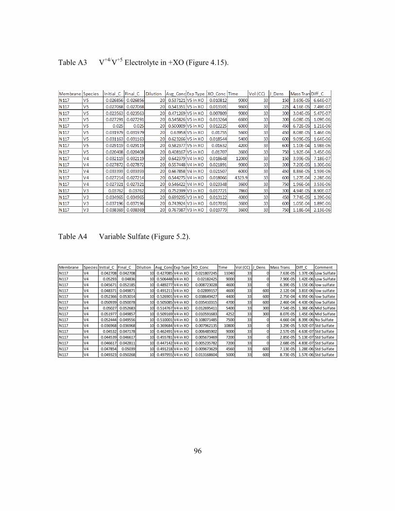
96
Table A3 V+4/
V+5
Electrolyte in +XO (Figure 4.15).
Table A4 Variable Sulfate (Figure 5.2).
Membrane Species Initial_C Final_C Dilution Avg_Conc Exp Type XO_Conc Time Vol (CC) J_Dens Mass Trans Diff_C Comment
N117 V4 0.042708 0.042708 10 0.427085 V4 in XO 0.021807245 11040 33 0 7.63E-05 1.37E-06 Low Sulfate
N117 V4 0.05293 0.04836 10 0.506448 V4 in XO 0.02182425 9000 33 0 7.90E-05 1.42E-06 Low Sulfate
N117 V4 0.045671 0.052185 10 0.489277 V4 in XO 0.008723028 4600 33 0 6.39E-05 1.15E-06 low sulfate
N117 V4 0.048371 0.049871 10 0.491211 V4 in XO 0.02899157 4600 33 600 2.12E-04 3.81E-06 low sulfate
N117 V4 0.052366 0.053014 10 0.526901 V4 in XO 0.038649427 4400 33 600 2.75E-04 4.95E-06 low Sulfate
N117 V4 0.050939 0.050078 10 0.505085 V4 in XO 0.035410315 4700 33 600 2.46E-04 4.43E-06 low Sulfate
N117 V4 0.05027 0.052683 10 0.514767 V4 in XO 0.012695411 5400 33 300 7.54E-05 1.36E-06 Mid Sulfate
N117 V4 0.051977 0.049857 10 0.509169 V4 in XO 0.010591683 4252 33 300 8.07E-05 1.45E-06 Mid Sulfate
N117 V4 0.052444 0.049556 10 0.510001 V4 in XO 0.108071485 7500 33 0 4.66E-04 8.39E-06 No Sulfate
N117 V4 0.036968 0.036968 10 0.369684 V4 in XO 0.007962135 10800 33 0 3.29E-05 5.92E-07 Std Sulfate
N117 V4 0.04532 0.047178 10 0.462491 V4 in XO 0.006485902 9000 33 0 2.57E-05 4.63E-07 Std Sulfate
N117 V4 0.044539 0.046617 10 0.455781 V4 in XO 0.005673469 7200 33 0 2.85E-05 5.13E-07 Std Sulfate
N117 V4 0.046617 0.042811 10 0.447142 V4 in XO 0.005235782 7200 33 0 2.68E-05 4.83E-07 Std Sulfate
N117 V4 0.047854 0.05039 10 0.491218 V4 in XO 0.009673629 4560 33 600 7.13E-05 1.28E-06 Std Sulfate
N117 V4 0.049323 0.050268 10 0.497955 V4 in XO 0.013168604 5000 33 600 8.73E-05 1.57E-06 Std Sulfate
97
References
1. M. Rychcik and M. Skyllas-Kazacos, “Characteristics of a new all-vanadium
redox flow battery”, J. Power Sources, 22 (1988) 59-67.
2. K.W. Knehr, E. Kumbur,” Open circuit voltage of vanadium redox flow
batteries: Discrepancy between models and experiments”, Electrochemistry
Communications, 13 (2011) 342-345.
3. E. Kjeang, B. Proctorm A. Brolo, D. Harrington, N. Djilali, D. Sinton, “High
performance microfluidic vanadium redox fuel cell”, Electrochimica Acta, 52
(2007) 4942–4946.
4. A. Tang, J. Bao, M. Skylass-Kazacos, “Dynamic modeling of the effects of
ion diffusion and side reactions on the capacity loss for vanadium redox flow
battery”, J. Power Sources, 196 (2011) 10737-10747.
5. K.W. Knehr, E. Agar, C. Dennison, A. Kalidindi, and E. Kumbar, “A
Transient Vanadium Flow Battery Model Incorporating Vanadium Crossover
and Water Transport through the Membrane”, J. Electrochem. Soc., 159
(2012) A1446-A1459.
6. F. Grossmith, P. Llewellyn, A.G. Fane, M. Skyllas-Kazacos, “Evaluation of
membranes for all-vanadium redox cell”, Proc. Electrochem. Soc. Symp.,
Honolulu, October 1988, pp. 363-374.
7. E. Wiedemann, A. Heintz, R.N. Lichtenthaler, “Transport properties of
vanadium ions in cation exchange membranes: Determination of diffusion
coefficients using a dialysis cell”, J. Membrane Science ,141 (1998) 215-221
8. C. Sun, J. Chen, H. Zhang, X. Han, Q. Luo, “Investigations on transfer of
water and vanadium ions across Nafion membrane in an operating vanadium
redox flow battery”, J. Power Sources, 195 (2010) 890-897.
9. Q. Luo, L. Li, Z. Nie, W. Wang, X. Wei, B. Li, B. Chen, Z. Yang, “In-situ
investigation of vanadium ion transport in redox flow battery”, J. Power
Sources, 218 (2012) 15-20.
10. Q. Liu, G. Grim, A. Papandrew, A. Turbin, T. Zawodzinski, M. Mench, “High
Performance Vanadium Redox Flow Batteries with Optimized Electrode
Configuration and Membrane Selection”, J. Electrochem. Soc., 159 (2012),
A1246-A1252.
11. M. Skyllas-Kazacos, M. Kazacos, “State of charge monitoring methods for
vanadium redox flow battery control”, J. Power Sources, 2011, 196, 8822-
8827.
12. Z. Tang, D. Aaron, A. Papandrew, T. Zawodzinski, “Monitoring the State of
Charge of Operating Vanadium Redox Flow Batteries”, ECS Transactions,
2012, 41 (23), 1-9.
13. P. Blanc, C. Madic, J. P. Launay, “ Spectrophotometric identification of a
mixed-vlaence cation-cation complex between aquadioxovanadium (V) and
aquaovanadium (IV) ions in perchloric, sulfuric, and hydrochloric acid
media”, Inorganic Chemistry, 1982, 21, 2923-2928.

98
14. K. Okamoto, J. Woo-Sik, H. Tomiyasu, H. Fukutomi, “Vanadium-51 NMR
line-broadening in the mixture of dioxovanadium(V) and oxovanadium(IV)
ions in perchloric acid Solution”, Inorganica Chimica Acta. 1988, 143, 217-
221.
15. J. Newman, K. Thomas-Alyea, Electrochemical Systems, 3rd Edition
(Hoboken NJ: Wiley, 2004).
16. K. Knehr, E. Agar, C. Dennison, A. Kalidindi, E. Kumbar, “A Transient
Vanadium Flow Battery Model Incorporating Vanadium Crossover and Water
Transport through the Membrane”, J. of the Electrochemical Soc., 159 (2012)
A1446-1459.
17. P.H. Michael, “A Multicomponent Model for the Vanadium Redox Flow
Battery”, Unpublished Masters Thesis, The University of Texas, Austin TX
(2012).
18. R.M. Darling and M.L Perry, “Pseudo-Steady-State Flow Battery
Experiments”, paper #B6-0480 to be presented at the 223rd
meeting of the
Electrochemical Society. Toronto, Canada (2013).
19. M.L. Perry, R.M. Darling, R. Zaffou, “High Power Density Flow Battery
Cells”, paper #B6-0476 to be presented at the 223rd
meeting of the
Electrochemical Society. Toronto, Canada (2013).
20. W.B. Stine and M. Geyer, “Power from the Sun”, published online
http://www.powerfromthesun.net/book.html, (2001).