copyright 2017 medical ip - tutorial medip v.1.0.0.9 01 ... ip... · medical images and creating 3d...
TRANSCRIPT
Copyright 2017 Medical IP - Tutorial Medip v.1.0.0.9 01/2018, Revision 1.0.0.2

ME
DIP
MA
NU
AL
| 1
List of Contents 1. Introduction . . . . . . . . . . . . . . . . . . . . . . . . . . . . . . . . . . . . . . . . . . . . . . . . . . . . . . . . . 2
2. Overview . . . . . . . . . . . . . . . . . . . . . . . . . . . . . . . . . . . . . . . . . . . . . . . . . . . . . . . . . . . . . . 3
2-1 Medical IP Overview . . . . . . . . . . . . . . . . . . . . . . . . . . . . . . . . . . . . . . . . . . . . . . . . . . . . . 3
2-2 Medip History . . . . . . . . . . . . . . . . . . . . . . . . . . . . . . . . . . . . . . . . . . . . . . . . . . . . . . . . . . . . 4
2-3 From Image to Model . . . . . . . . . . . . . . . . . . . . . . . . . . . . . . . . . . . . . . . . . . . . . . . . . . . . 4 2-4 STL File Explanation . . . . . . . . . . . . . . . . . . . . . . . . . . . . . . . . . . . . . . . . . . . . . . . . . . . . 4
2-5 Medical Imaging. . . . . . . . . . . . . . . . . . . . . . . . . . . . . . . . . . . . . . . . . . . . . . . . . . . . . . . . . . 4
2-6 Before You Start. . . . . . . . . . . . . . . . . . . . . . . . . . . . . . . . . . . . . . . . . . . . . . . . . . . . . . . . . . 5
2-6-1 Download and Install Medip. . . . . . . . . . . . . . . . . . . . . . . . . . . . . . . . . . . . . . . . . . 5
2-6-2 How to activate Medip software. . . . . . . . . . . . . . . . . . . . . . . . . . . . . . . . . . . . . . 7
2-6-3 How to Use this Tutorial. . . . . . . . . . . . . . . . . . . . . . . . . . . . . . . . . . . . . . . . . . . . . . 7
3. Navigation . . . . . . . . . . . . . . . . . . . . . . . . . . . . . . . . . . . . . . . . . . . . . . . . . . . . . . . . . . . 8
3-1 Explanation . . . . . . . . . . . . . . . . . . . . . . . . . . . . . . . . . . . . . . . . . . . . . . . . . . . . . . . . . . . . . . 8
3-1-1 Main Viewer . . . . . . . . . . . . . . . . . . . . . . . . . . . . . . . . . . . . . . . . . . . . . . . . . . . . . . . . . . 8
3-1-2 Main Toolbar . . . . . . . . . . . . . . . . . . . . . . . . . . . . . . . . . . . . . . . . . . . . . . . . . . . . . . . . . 9
3-1-3 Icon List . . . . . . . . . . . . . . . . . . . . . . . . . . . . . . . . . . . . . . . . . . . . . . . . . . . . . . . . . . . . . . 9
3-1-4 Segmentation Toolbar . . . . . . . . . . . . . . . . . . . . . . . . . . . . . . . . . . . . . . . . . . . . . . . 13
3-1-5 All Shortcuts. . . . . . . . . . . . . . . . . . . . . . . . . . . . . . . . . . . . . . . . . . . . . . . . . . . . . . . . . . 13
3-2 Step by Step Tutorial . . . . . . . . . . . . . . . . . . . . . . . . . . . . . . . . . . . . . . . . . . . . . . . . . . . 14
3-2-1 Zooming and Panning. . . . . . . . . . . . . . . . . . . . . . . . . . . . . . . . . . . . . . . . . . . . . . . . 14
3-2-1 Segmentation Toolbar. . . . . . . . . . . . . . . . . . . . . . . . . . . . . . . . . . . . . . . . . . . . . . . . . 14
4. Import . . . . . . . . . . . . . . . . . . . . . . . . . . . . . . . . . . . . . . . . . . . . . . . . . . . . . . . . . . . . . . . . . 16
5. Segmentation . . . . . . . . . . . . . . . . . . . . . . . . . . . . . . . . . . . . . . . . . . . . . . . . . . . . . 17
5-1 Explanation . . . . . . . . . . . . . . . . . . . . . . . . . . . . . . . . . . . . . . . . . . . . . . . . . . . . . . . . . . . . . . 17
5-2 Step by Step Tutorial. . . . . . . . . . . . . . . . . . . . . . . . . . . . . . . . . . . . . . . . . . . . . . . . . . . . 17
5-2-1 Region Growing . . . . . . . . . . . . . . . . . . . . . . . . . . . . . . . . . . . . . . . . . . . . . . . . . . . . . . . . 18
5-2-2 ROI List Box . . . . . . . . . . . . . . . . . . . . . . . . . . . . . . . . . . . . . . . . . . . . . . . . . . . . . . . . . 19
6. Visualization . . . . . . . . . . . . . . . . . . . . . . . . . . . . . . . . . . . . . . . . . . . . . . . . . . . . . . . 33
6-1 Explanation . . . . . . . . . . . . . . . . . . . . . . . . . . . . . . . . . . . . . . . . . . . . . . . . . . . . . . . . . . . . . . 33
6-2 Step by Step Tutorial . . . . . . . . . . . . . . . . . . . . . . . . . . . . . . . . . . . . . . . . . . . . . . . . . . . . 33
7. Conlusion . . . . . . . . . . . . . . . . . . . . . . . . . . . . . . . . . . . . . . . . . . . . . . . . . . . . . . . . . . . . 37
8. Contact Us . . . . . . . . . . . . . . . . . . . . . . . . . . . . . . . . . . . . . . . . . . . . . . . . . . . . . . . . . . 38

ME
DIP
MA
NU
AL
| 2
1. Introduction Medip (Medical Image Processing) is a Medical IP’s software for processing
medical images and creating 3D models. Medip uses 2D cross-sectional
medical images such as from computed tomography (CT) and magnetic
resonance imaging (MRI) to construct 3D models, which can then be directly
linked to rapid prototyping, computer-aided design (CAD), surgical simulation
and advanced engineering analysis.
ME
DIP
MA
NU
AL
| 3
2. Overview
2–1 Medical IP
Overview
Medical IP is an international company, best known for its activities in the field
of medical imaging and prototyping. Started in 2015 as a spin off corporation
from the Seoul National University Hospital, it began as a rapid prototyping
service bureau. Since then, Medical IP has grown into the world’s rapid
prototype producer. The company also enjoys a worldwide reputation as
provider of innovative software solutions, such 3D Printing Technology and
Virtual-Augmented Reality for surgery simulation.
For the medical and rapid prototyping industries, Medical IP offers complete
software solution for 3D visualization. Medip is the medical image based
processing tool for creating 3D models, and linking the models to rapid
prototyping (RP). It allows user to import patients’ data, attempts segmentation,
and prepare a 3D object (STL) files for additive fabrication as well as performs
easy mesh and geometry manipulation. This STL file further can be imported
in any 3D printer in the world. Owning its intellectual rights on customized 3D
printing technologies, Medical IP moreover provides patient-specific 3D
fabricated organ service, called Anatdel. It supports surgeons, doctors and
medical students to understand and simulate surgical planning that match to
the operation in the operating room. MAVR (Medical Augmented and Virtual
Reality software) on the other hand is an extension of Medip which enable
users to visualize the volumetric 3D model into virtual and augmented reality
visualization. It support all of NifTI-1 files (.nii), which widely used for medical
imaging. It allows user to virtually simulate and slicing each organ and
performing surgical simulation before operation. As one of the Medical IP one
stop solution, MAVR completes overall visualization both real and augmented
world.
ME
DIP
MA
NU
AL
| 4
2–2 Medip History
2-3 From Image to
Model
2 - 4 File Explanation
2 - 5 Medical Imaging
After the start of the company Medical IP in 2015, it didn’t take too long for the
company to see the analogy between RP and CT (or MRI) images. In RP, a
3D model is built slice per slice, whereas a CT scanner does the reverse, it
breaks down a 3D model (the human body) into a stack of image slices. In
2015, Medical IP wrote software that linked the image information to RP
models. Since then, Medip was born.
A sequence of medical images can be loaded into software, Medip, and this
usually consists of image in the XY plane (axial images). Medip then calculates
and create images in the XZ(coronal) and YZ (sagittal) direction. Based on this
method, those sequence of medical images then reconstructed as 3D
rendering. The key to converting 3D model into RP is a process called
segmentation. From the 3D rendering, then user draws specific targeted organ
which will be used for volume and surface rendering (masking), and this
surface further can be exported in STL format so it can be printed in the 3D
printing machine.
STL or STereoLithography is a file format as a Standard Triangle Language.
This file format is widely used for rapid prototyping, 3D printing and computer-
aided manufacturing (CAD) because of its simple file structure to match any
contour desired. It describes only the surface of geometry of 3D object without
any color, texture, etc.
Medical imaging is the technique and process of creating visual
representations of the interior body for clinical analysis and medical
intervention. It is a part of biological imaging and incorporate radiology which
aim to reveal internal structures hidden by the skin, bones, as well as to
diagnose and treat disease. It uses several modality medical images including
CT, and MRI. And the process for visualizing the specific targeted organ uses
some segmentation techniques, image enhancements, noise reduction, etc.
Accurate segmentation is important in order to extract meaningful information
from the images.
ME
DIP
MA
NU
AL
| 5
2 - 6 Before You Start
2-6-1 Download and Install
Medip
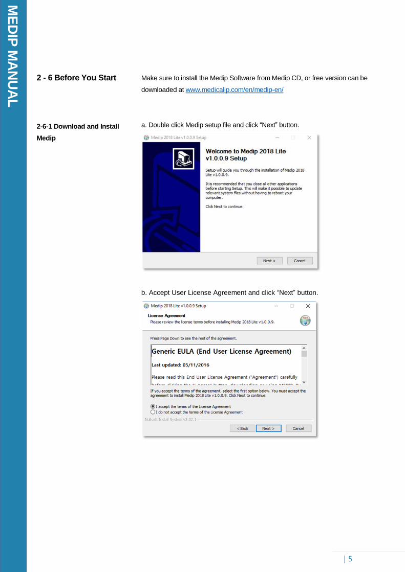
Make sure to install the Medip Software from Medip CD, or free version can be
downloaded at www.medicalip.com/en/medip-en/
a. Double click Medip setup file and click “Next” button.
b. Accept User License Agreement and click “Next” button.

ME
DIP
MA
NU
AL
| 6
c. Choose installation folder, and click “Next” button.
d. Accept User License Agreement and click “Next” button.
e. Finish

ME
DIP
MA
NU
AL
| 7
2-6-2 How to activate Medip
software
2-6-3 How to Use this
Tutorial
a. Get the license code from Medical IP.
b. Open your Medip software → Go to "Info" at the main toolbar
c. Insert activation key
You will see the following conventions while following the step by step
section in this tutorial:
.
Phrases in bold (example) represent tools, buttons and functions
in Medip.
Anything in double quotation marks ("example") signifies exactly
what you will see in Medip (not functions)

ME
DIP
MA
NU
AL
| 8
3. Navigation
3 - 1 Explanation
3-1-1 Main viewer
Tools to learn : Navigation, Segmentation Toolbar, Rendering Toolbar
To process data in Medip, a set of stacked 2D cross-sectional images is first
imported. These 2D images commonly in the DICOM (.dcm) format, come
from medical scanning equipment. Once the stacked images are imported,
they can be viewed and edited using the various tools available in Medip. The
quality of the 3D images that Medip can create directly correlates to the slice
thickness and pixel size of the 2D images.
The Medip screen is broken up into four main views; 3D, axial, coronal, sagittal.
Users can think of axial as a top down view, coronal as a front view, and
sagittal as a left view. The axial view comes from the imported stack of images.
To obtain the coronal and sagittal views, Medip transposes the axial images
into their respective positions. The 3D pane is where 3D models are visualized.
Clicking on an image with the left mouse button automatically updates your
location in all views. There are eight additional thumbnails on the right side,
four thumbnails at the top represent four files upfront the current image position,
and vice versa.
Each of the 2D views contains a slice number and coordinate at the top-left
corner and slice sliding bar at the bottom. You can use PageUp and
PageDown keyboard to move the slider. To make it a single viewer, you can
click space keyboard
ME
DIP
MA
NU
AL
| 9
3-1-2 Main Toolbar
3-1-3 Icon List
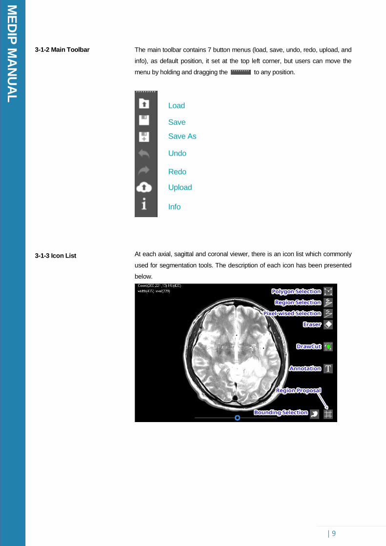
The main toolbar contains 7 button menus (load, save, undo, redo, upload, and
info), as default position, it set at the top left corner, but users can move the
menu by holding and dragging the to any position.
At each axial, sagittal and coronal viewer, there is an icon list which commonly
used for segmentation tools. The description of each icon has been presented
below.
Load
Save
Save As
Undo
Redo
Upload
Info
ME
DIP
MA
NU
AL
| 10
a. Polygon Selection
b. Region Selection
c. Pixel-wised Selection
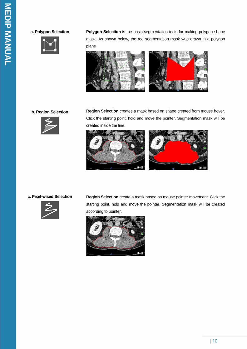
Polygon Selection is the basic segmentation tools for making polygon shape
mask. As shown below, the red segmentation mask was drawn in a polygon
plane
Region Selection creates a mask based on shape created from mouse hover.
Click the starting point, hold and move the pointer. Segmentation mask will be
created inside the line.
Region Selection create a mask based on mouse pointer movement. Click the
starting point, hold and move the pointer. Segmentation mask will be created
according to pointer.
ME
DIP
MA
NU
AL
| 11
d. Eraser
e. Draw cut
f. Annotation
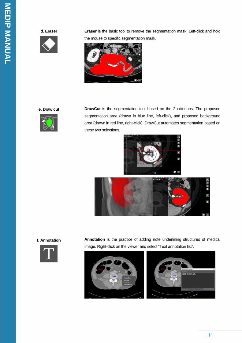
Eraser is the basic tool to remove the segmentation mask. Left-click and hold
the mouse to specific segmentation mask.
DrawCut is the segmentation tool based on the 2 criterions. The proposed
segmentation area (drawn in blue line, left-click), and proposed background
area (drawn in red line, right-click). DrawCut automates segmentation based on
these two selections.
Annotation is the practice of adding note underlining structures of medical
image. Right-click on the viewer and select “Text annotation list”.

ME
DIP
MA
NU
AL
| 12
g. Region Proposal
h. Boundary Viewer
Region Proposal can be seen as “working region”. Everything inside working
region will be calculated, and vice versa. Setting the working region can be
done easily by moving the white line in all image viewer.
Boundary Viewer is the tool for viewing the border of segmentation mask.
ME
DIP
MA
NU
AL
| 13
3-1-4 Segmentation Toolbar
3-1-5 All Shortcuts
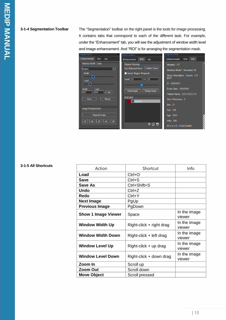
The “Segmentation” toolbar on the right panel is the tools for image processing.
It contains tabs that correspond to each of the different task. For example,
under the “Enhancement” tab, you will see the adjustment of window width level
and image enhancement. And “ROI” is for arranging the segmentation mask.
Action Shortcut Info
Load Ctrl+O
Save Ctrl+S
Save As Ctrl+Shift+S
Undo Ctrl+Z
Redo Ctrl+Y
Next Image PgUp
Previous Image PgDown
Show 1 Image Viewer Space In the image viewer
Window Width Up Right-click + right drag In the image viewer
Window Width Down Right-click + left drag In the image viewer
Window Level Up Right-click + up drag In the image viewer
Window Level Down Right-click + down drag In the image viewer
Zoom In Scroll up
Zoom Out Scroll down
Move Object Scroll pressed
ME
DIP
MA
NU
AL
| 14
3-2 Step by Step
Tutorial
3-2-1 Zooming and Panning
3-2-1 Segmentation Toolbar
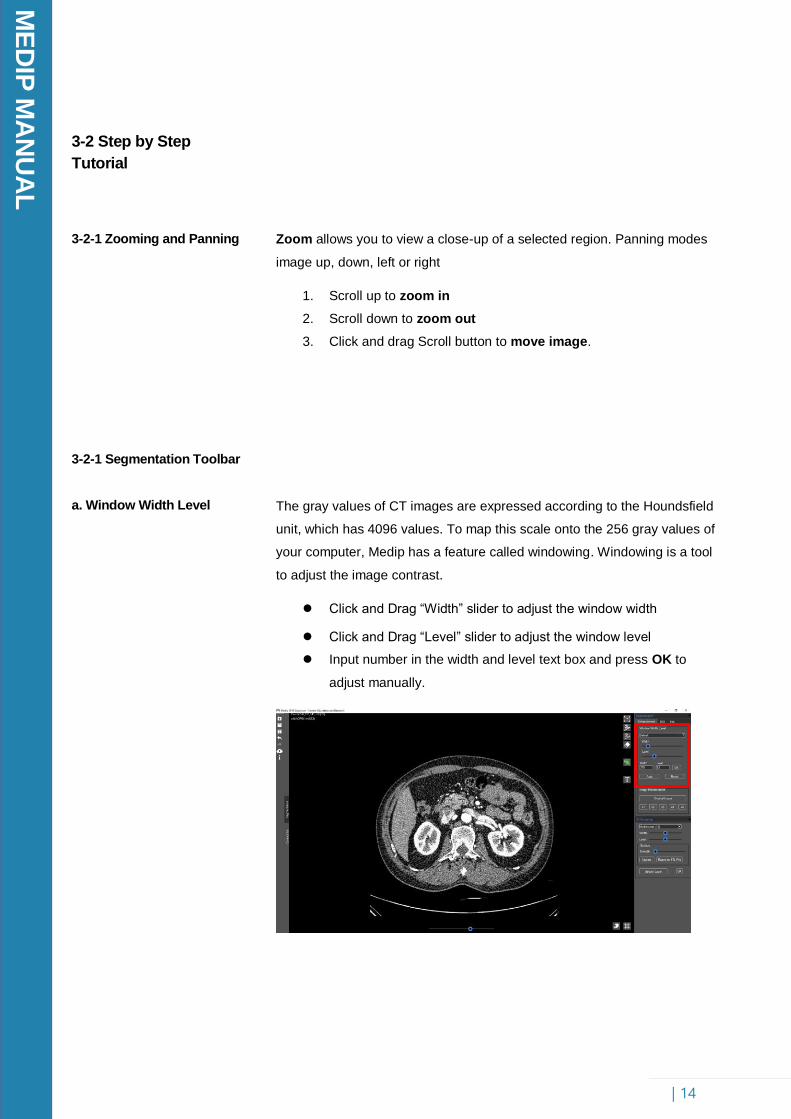
a. Window Width Level
Zoom allows you to view a close-up of a selected region. Panning modes
image up, down, left or right
1. Scroll up to zoom in
2. Scroll down to zoom out
3. Click and drag Scroll button to move image.
The gray values of CT images are expressed according to the Houndsfield
unit, which has 4096 values. To map this scale onto the 256 gray values of
your computer, Medip has a feature called windowing. Windowing is a tool
to adjust the image contrast.
Click and Drag “Width” slider to adjust the window width
Click and Drag “Level” slider to adjust the window level
Input number in the width and level text box and press OK to
adjust manually.
ME
DIP
MA
NU
AL
| 15
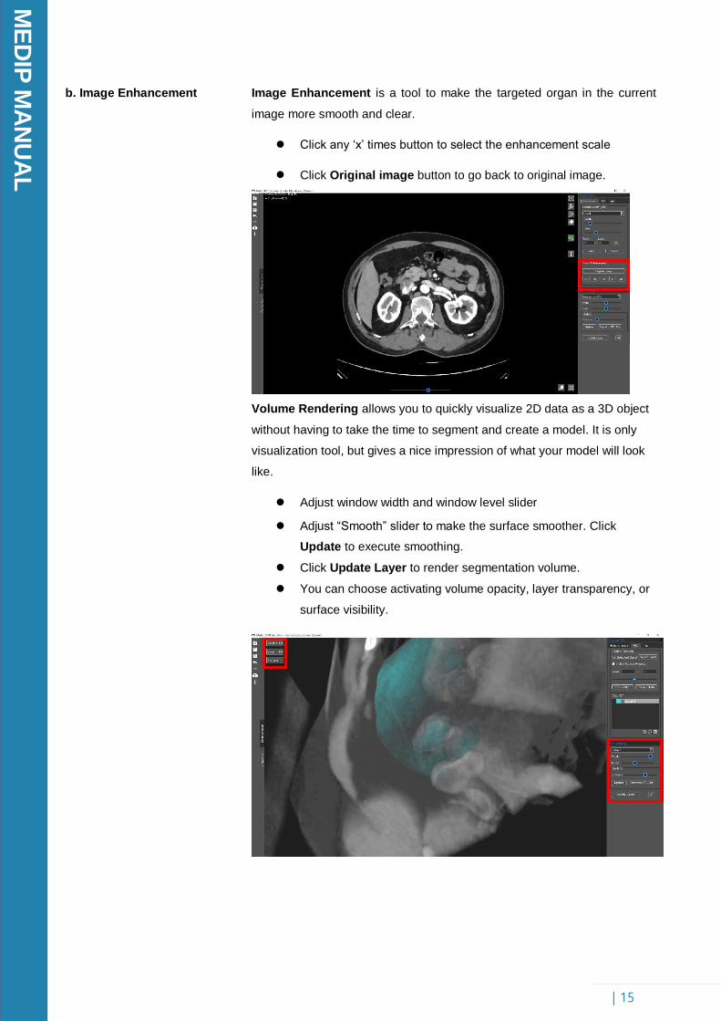
b. Image Enhancement Image Enhancement is a tool to make the targeted organ in the current
image more smooth and clear.
Click any ‘x’ times button to select the enhancement scale
Click Original image button to go back to original image.
Volume Rendering allows you to quickly visualize 2D data as a 3D object
without having to take the time to segment and create a model. It is only
visualization tool, but gives a nice impression of what your model will look
like.
Adjust window width and window level slider
Adjust “Smooth” slider to make the surface smoother. Click
Update to execute smoothing.
Click Update Layer to render segmentation volume.
You can choose activating volume opacity, layer transparency, or
surface visibility.
ME
DIP
MA
NU
AL
| 16
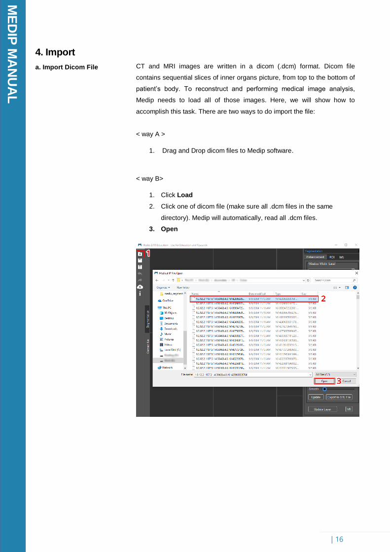
4. Import
a. Import Dicom File
CT and MRI images are written in a dicom (.dcm) format. Dicom file
contains sequential slices of inner organs picture, from top to the bottom of
patient’s body. To reconstruct and performing medical image analysis,
Medip needs to load all of those images. Here, we will show how to
accomplish this task. There are two ways to do import the file:
< way A >
1. Drag and Drop dicom files to Medip software.
< way B>
1. Click Load
2. Click one of dicom file (make sure all .dcm files in the same
directory). Medip will automatically, read all .dcm files.
3. Open
ME
DIP
MA
NU
AL
| 17
5. Segmentation
5-1 Explanation
3-2 Step by Step
Tutorial
Tools to learn: Region Proposal, Region Growing, basic editing tools
Segmentation is the main activity in Medip. Medip has several tools to
segment, or section, region of interest. Before doing the segmentation, we
have to set the Region Proposal ( ). It can be seen as segmentation
working area. By setting the region proposal, everything inside the region
will be processed, and vice versa. This tool also can be used for slicing the
3D rendering view.
In the “Segmentation Toolbar”, inside “ROI” tab, there is Region Growing
function. Region Growing is a mask created based on how surrounding
pixels compare to a selected datapoints, grey value, automatically
determining from the window level slider. This tool proves very useful for
segmenting such as blood vessels and nerves. To further segment various
of an image, Medip has a selection of editing tools. Pixel-wised Selection
can be helpful for manual segmentation. Region Selection, Polygon
Selection, and Eraser provide the tools needed to draw and erase the
mask. To perform the transformation from 2D to 3D, we only need to click
‘update’ the 3D rendering.
All of segmentation masks can be arranged inside “ROI LIST” box. The
mask that is selected in the “ROI” is considered the active mask. There are
several functions like Duplicate, Merge, Inverse, Erosion, Dilation, etc
for managing the segmentation mask.
Depending on the type of file output needed, Medip has various exporting
options including exporting the STL format. This file further can be imported
and printed using 3D printer.
Scenario : Your boss has asked you to review some scans and put
together a presentation displaying a patient’s anatomy. You will use Medip
to highlight the colon and bone structure, and create a 3D model to fully
display the patient’s anatomy. The procedures outlined below will show you
how to accomplish these tasks.
ME
DIP
MA
NU
AL
| 18
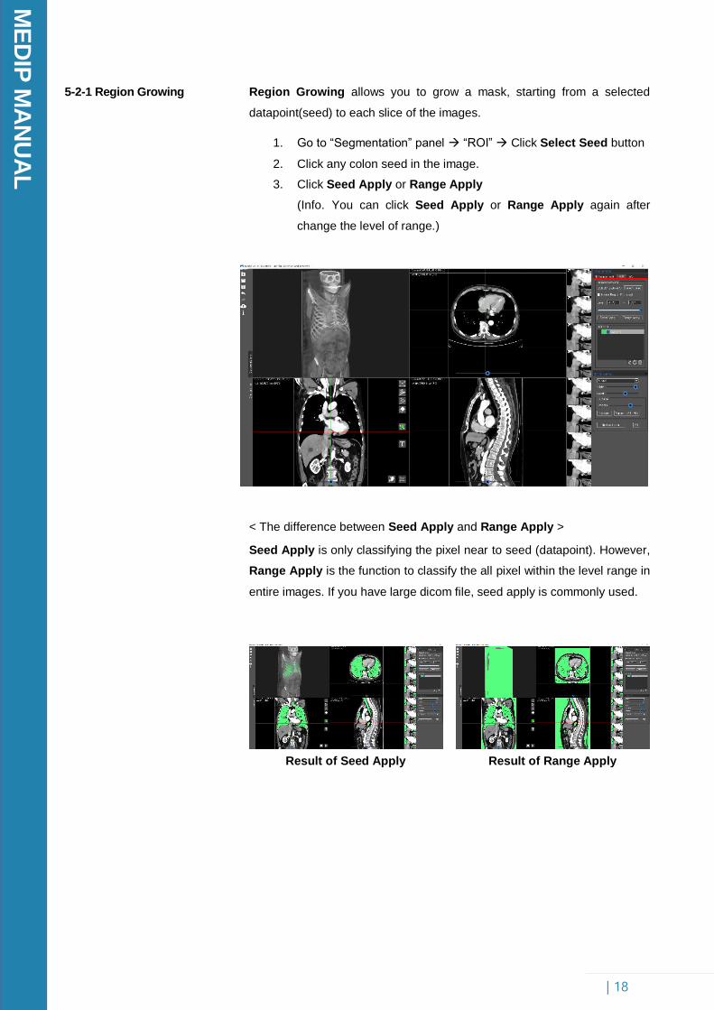
5-2-1 Region Growing
Region Growing allows you to grow a mask, starting from a selected
datapoint(seed) to each slice of the images.
1. Go to “Segmentation” panel “ROI” Click Select Seed button
2. Click any colon seed in the image.
3. Click Seed Apply or Range Apply
(Info. You can click Seed Apply or Range Apply again after
change the level of range.)
< The difference between Seed Apply and Range Apply >
Seed Apply is only classifying the pixel near to seed (datapoint). However,
Range Apply is the function to classify the all pixel within the level range in
entire images. If you have large dicom file, seed apply is commonly used.
5-2-2 ROI List Box
Result of Seed Apply Result of Range Apply
ME
DIP
MA
NU
AL
| 19
5-2-1 ROI List Box
New Layer
Medip provides several functions for maintaining the segmentation masks.
All functions listed below are shown when right clicked button triggered
inside the “ROI LIST” box.
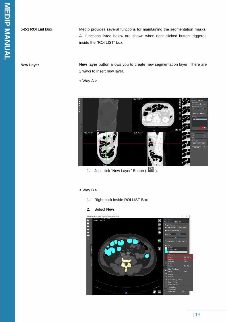
New layer button allows you to create new segmentation layer. There are
2 ways to insert new layer.
< Way A >
1. Just click “New Layer” Button ( ).
< Way B >
1. Right-click inside ROI LIST Box
2. Select New
ME
DIP
MA
NU
AL
| 20
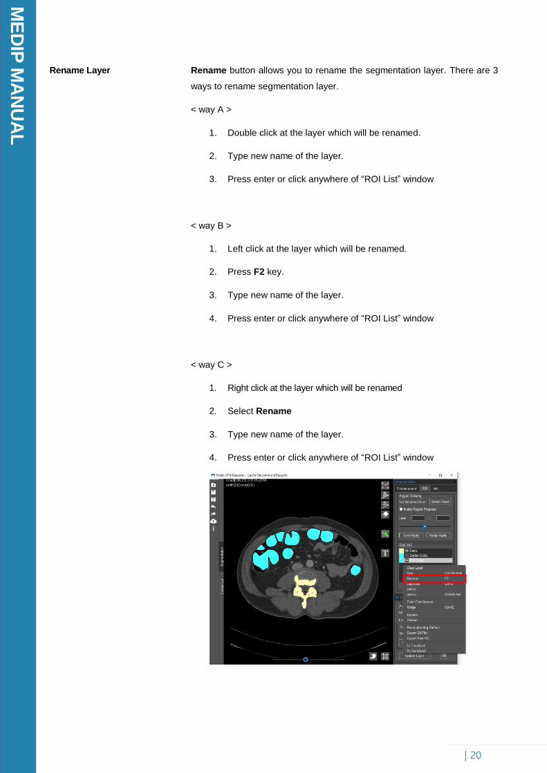
Rename Layer Rename button allows you to rename the segmentation layer. There are 3
ways to rename segmentation layer.
< way A >
1. Double click at the layer which will be renamed.
2. Type new name of the layer.
3. Press enter or click anywhere of “ROI List” window
< way B >
1. Left click at the layer which will be renamed.
2. Press F2 key.
3. Type new name of the layer.
4. Press enter or click anywhere of “ROI List” window
< way C >
1. Right click at the layer which will be renamed
2. Select Rename
3. Type new name of the layer.
4. Press enter or click anywhere of “ROI List” window
ME
DIP
MA
NU
AL
| 21
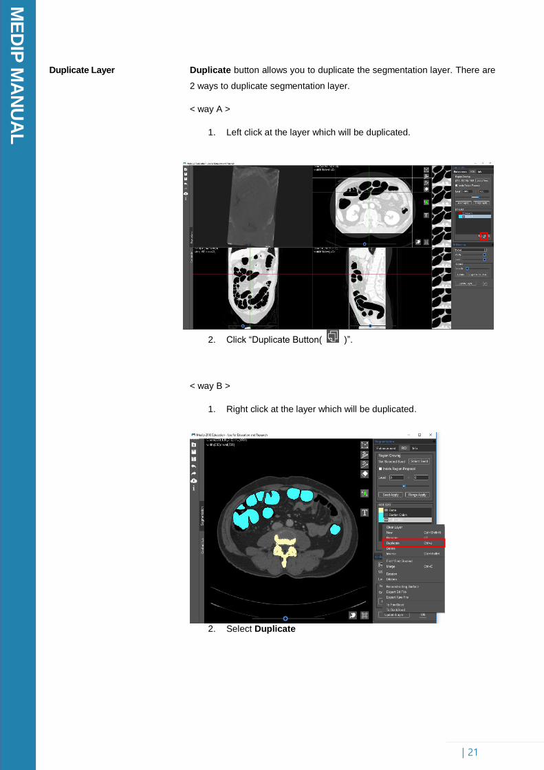
Duplicate Layer
Duplicate button allows you to duplicate the segmentation layer. There are
2 ways to duplicate segmentation layer.
< way A >
1. Left click at the layer which will be duplicated.
2. Click “Duplicate Button( )”.
< way B >
1. Right click at the layer which will be duplicated.
2. Select Duplicate
ME
DIP
MA
NU
AL
| 22
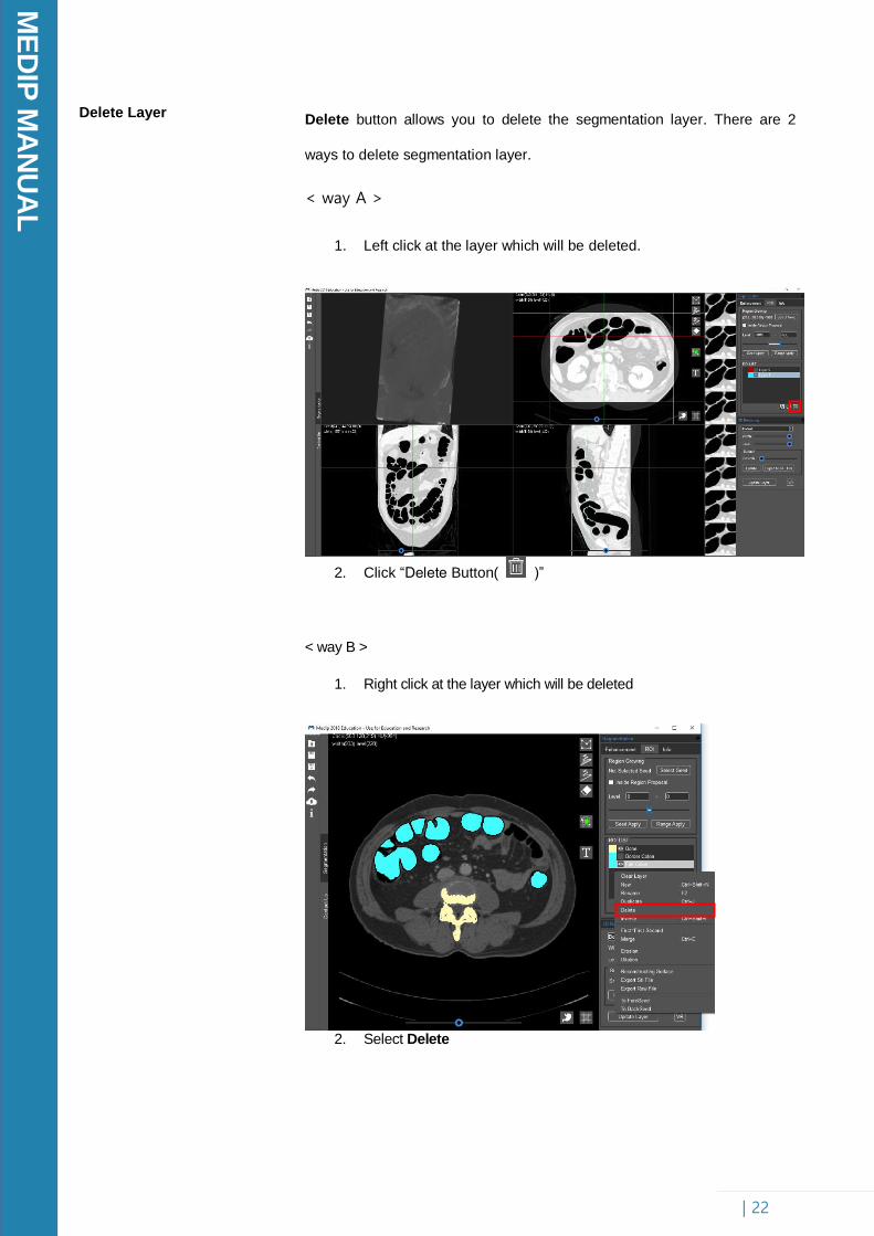
Delete Layer Delete button allows you to delete the segmentation layer. There are 2
ways to delete segmentation layer.
< way A >
1. Left click at the layer which will be deleted.
2. Click “Delete Button( )”
< way B >
1. Right click at the layer which will be deleted
2. Select Delete
ME
DIP
MA
NU
AL
| 23
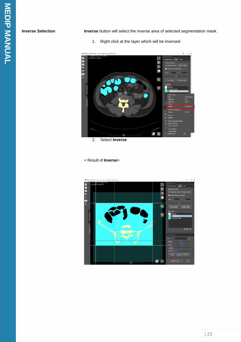
Inverse Selection Inverse button will select the inverse area of selected segmentation mask.
1. Right click at the layer which will be inversed
2. Select Inverse
< Result of Inverse>
ME
DIP
MA
NU
AL
| 24
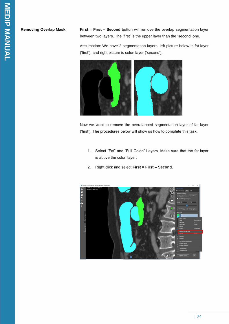
Removing Overlap Mask
First = First – Second button will remove the overlap segmentation layer
between two layers. The ‘first’ is the upper layer than the ‘second’ one.
Assumption: We have 2 segmentation layers, left picture below is fat layer
(‘first’), and right picture is colon layer (‘second’).
Now we want to remove the overalapped segmentation layer of fat layer
(‘first’). The procedures below will show us how to complete this task.
1. Select “Fat” and “Full Colon” Layers. Make sure that the fat layer
is above the colon layer.
2. Right click and select First = First – Second.
ME
DIP
MA
NU
AL
| 25
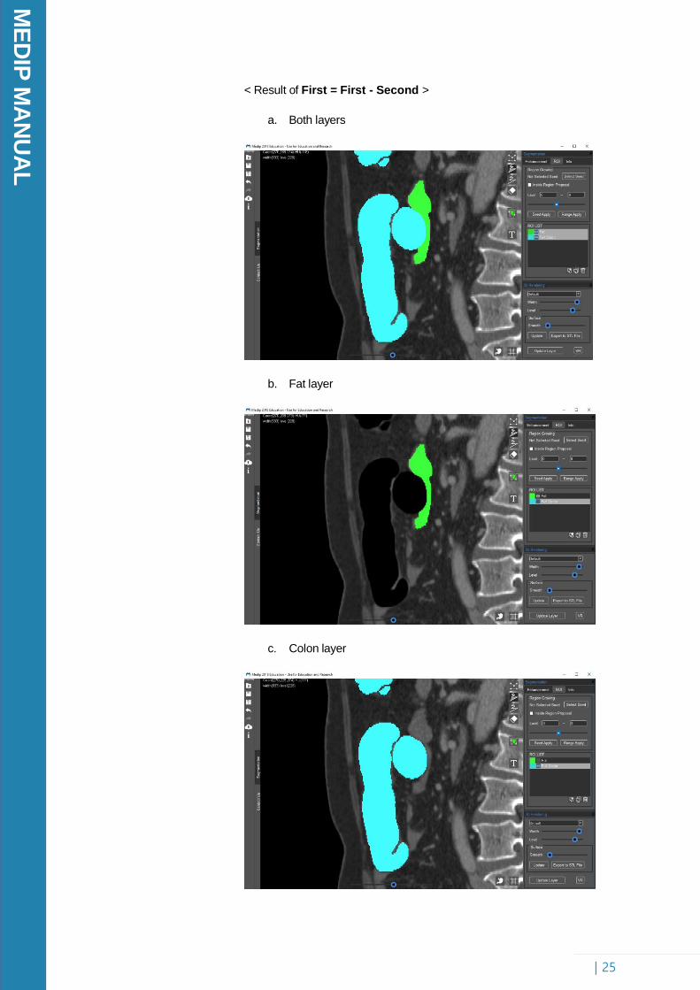
< Result of First = First - Second >
a. Both layers
b. Fat layer
c. Colon layer
ME
DIP
MA
NU
AL
| 26
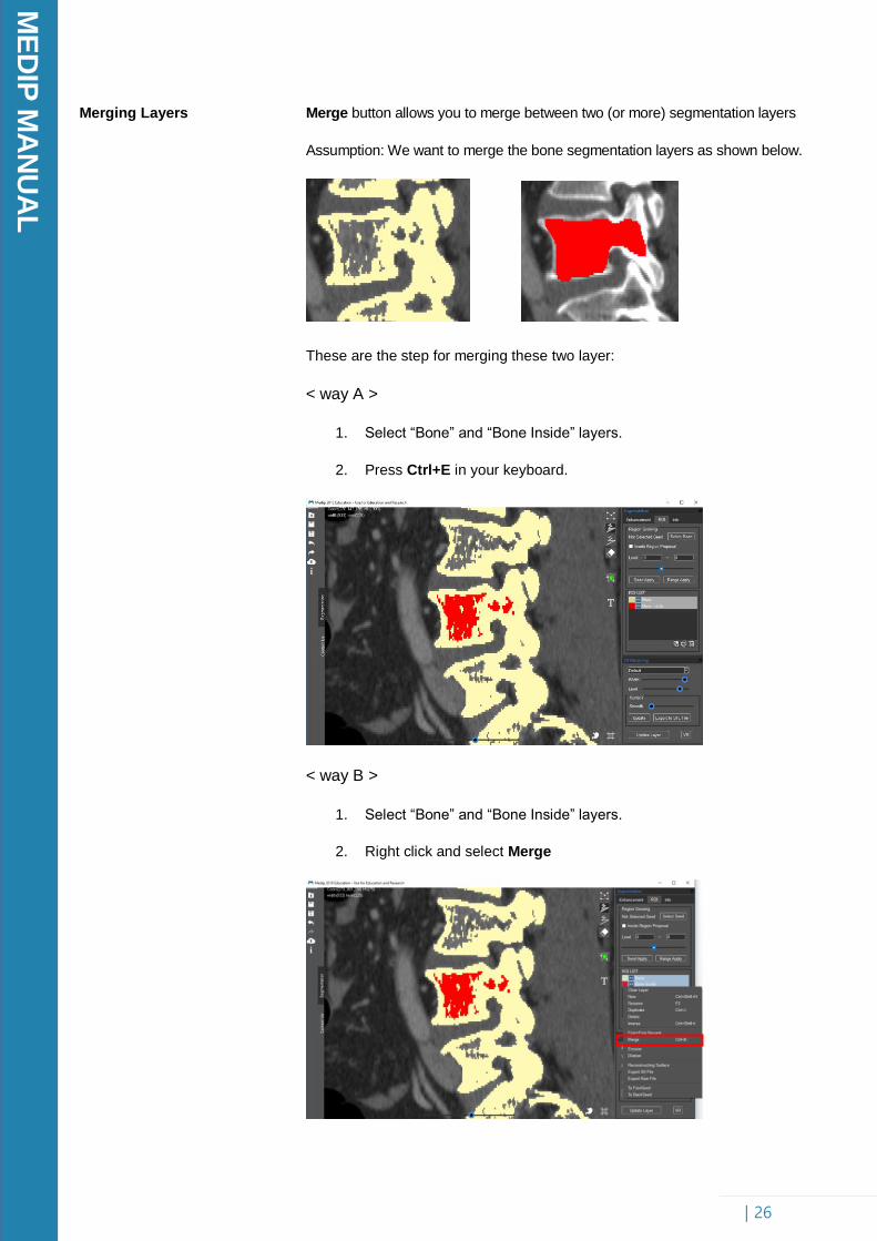
Merging Layers
Merge button allows you to merge between two (or more) segmentation layers
Assumption: We want to merge the bone segmentation layers as shown below.
These are the step for merging these two layer:
< way A >
1. Select “Bone” and “Bone Inside” layers.
2. Press Ctrl+E in your keyboard.
< way B >
1. Select “Bone” and “Bone Inside” layers.
2. Right click and select Merge

ME
DIP
MA
NU
AL
| 27
< Result of Merge Layers >
ME
DIP
MA
NU
AL
| 28
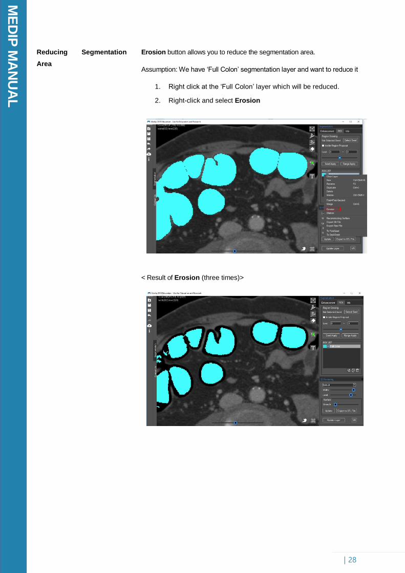
Reducing Segmentation
Area
Erosion button allows you to reduce the segmentation area.
Assumption: We have ‘Full Colon’ segmentation layer and want to reduce it
1. Right click at the ‘Full Colon’ layer which will be reduced.
2. Right-click and select Erosion
< Result of Erosion (three times)>
ME
DIP
MA
NU
AL
| 29
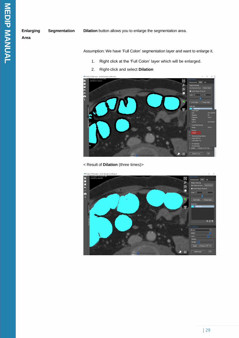
Enlarging Segmentation
Area
Dilation button allows you to enlarge the segmentation area.
Assumption: We have ‘Full Colon’ segmentation layer and want to enlarge it.
1. Right click at the ‘Full Colon’ layer which will be enlarged.
2. Right-click and select Dilation
< Result of Dilation (three times)>
ME
DIP
MA
NU
AL
| 30
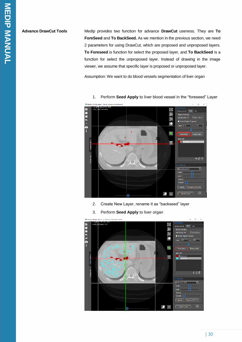
Advance DrawCut Tools
Medip provides two function for advance DrawCut useness. They are To
ForeSeed and To BackSeed. As we mention in the previous section, we need
2 parameters for using DrawCut, which are proposed and unproposed layers.
To Foreseed is function for select the proposed layer, and To BackSeed is a
function for select the unproposed layer. Instead of drawing in the image
viewer, we assume that specific layer is proposed or unproposed layer.
Assumption: We want to do blood vessels segmentation of liver organ
1. Perform Seed Apply to liver blood vessel in the “foreseed” Layer
2. Create New Layer, rename it as “backseed” layer
3. Perform Seed Apply to liver organ
ME
DIP
MA
NU
AL
| 31
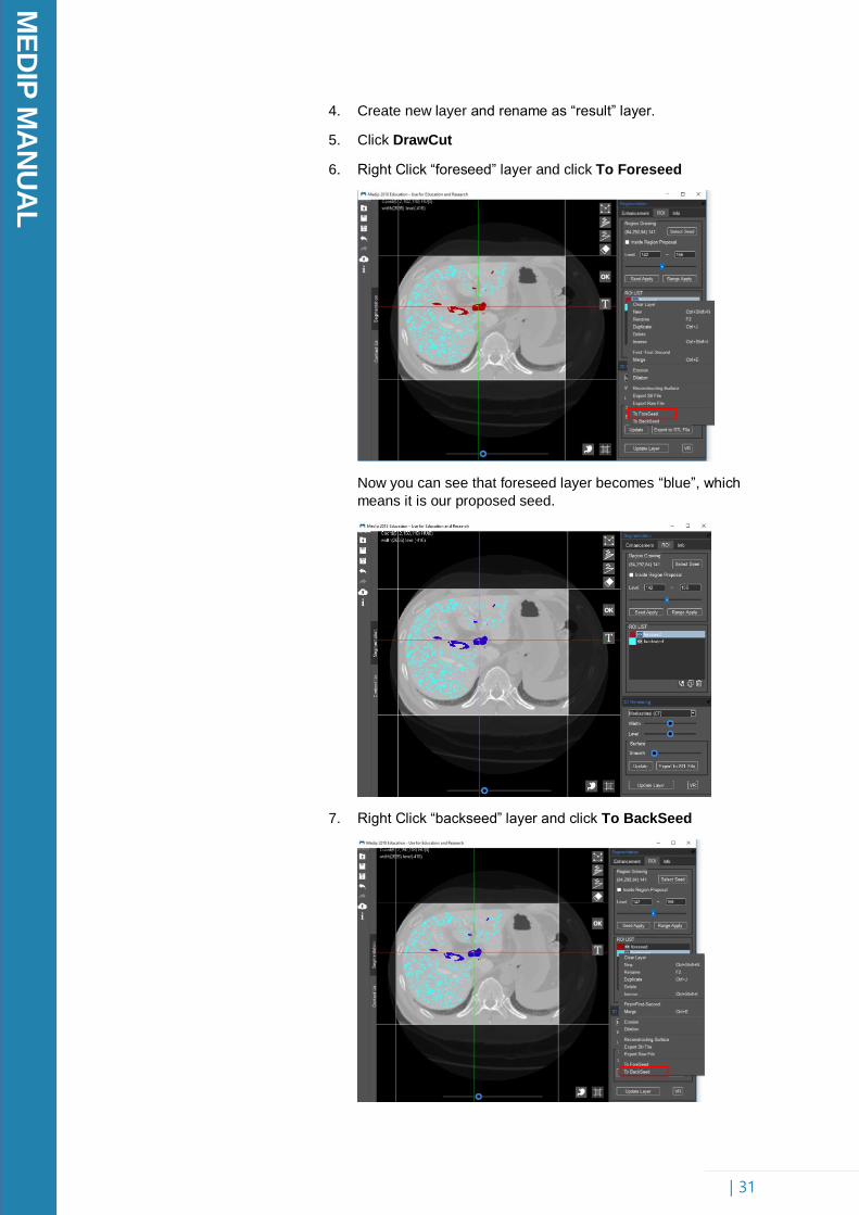
4. Create new layer and rename as “result” layer.
5. Click DrawCut
6. Right Click “foreseed” layer and click To Foreseed
Now you can see that foreseed layer becomes “blue”, which
means it is our proposed seed.
7. Right Click “backseed” layer and click To BackSeed
ME
DIP
MA
NU
AL
| 32
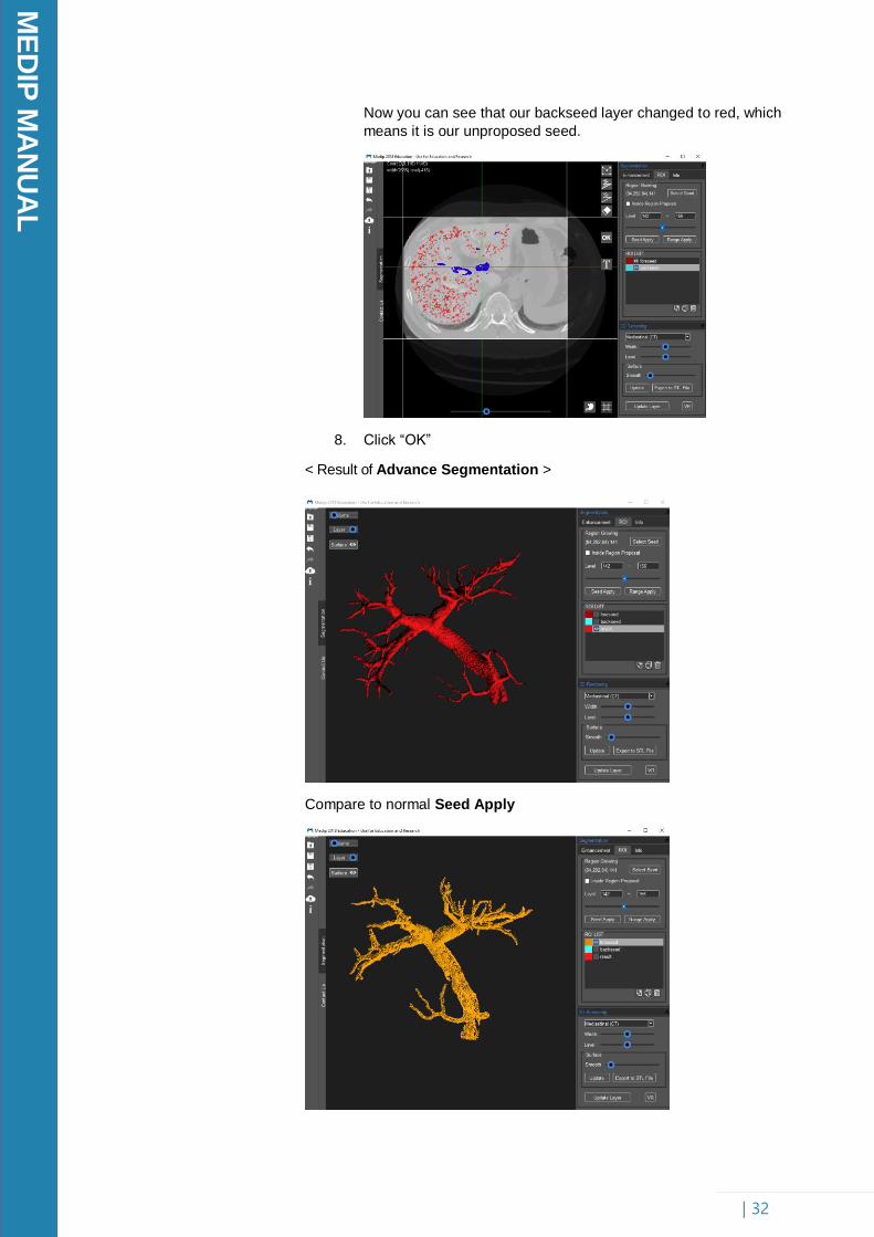
Now you can see that our backseed layer changed to red, which
means it is our unproposed seed.
8. Click “OK”
< Result of Advance Segmentation >
Compare to normal Seed Apply

ME
DIP
MA
NU
AL
| 33
6. Visualization
6-1 Explanation
6-2 Step by Step
Tutorial
Reconstructing Surface
Tools to learn: Surface Reconstruction, Export to STL File, Export to RAW
File
After finishing all organ segmentation, we can visualize it into 3D Model and
exporting it into STL file. This file furthermore can be printed using 3D printer
machine. In this section we will render 3D reconstruction and export it to STL
File and RAW File.
Reconstructing Surface allows you to render the 3D surface of segmented
organ.
1. Right click at the ‘Full Colon’ layer which will be reconstructed
2. Right-click and select Reconstructing Surface
< Result of Reconstructing Surface>

ME
DIP
MA
NU
AL
| 34
Surface Smoothing
Surface Smoothing allows you to smooth the surface of reconstructed 3D
model.
Assumption: We have performed surface reconstruction before.
1. Adjust the “Smooth” in 3D Rendering Toolbar.
2. Right-click and select Reconstructing Surface.
< Result of Reconstructing Surface>
ME
DIP
MA
NU
AL
| 35
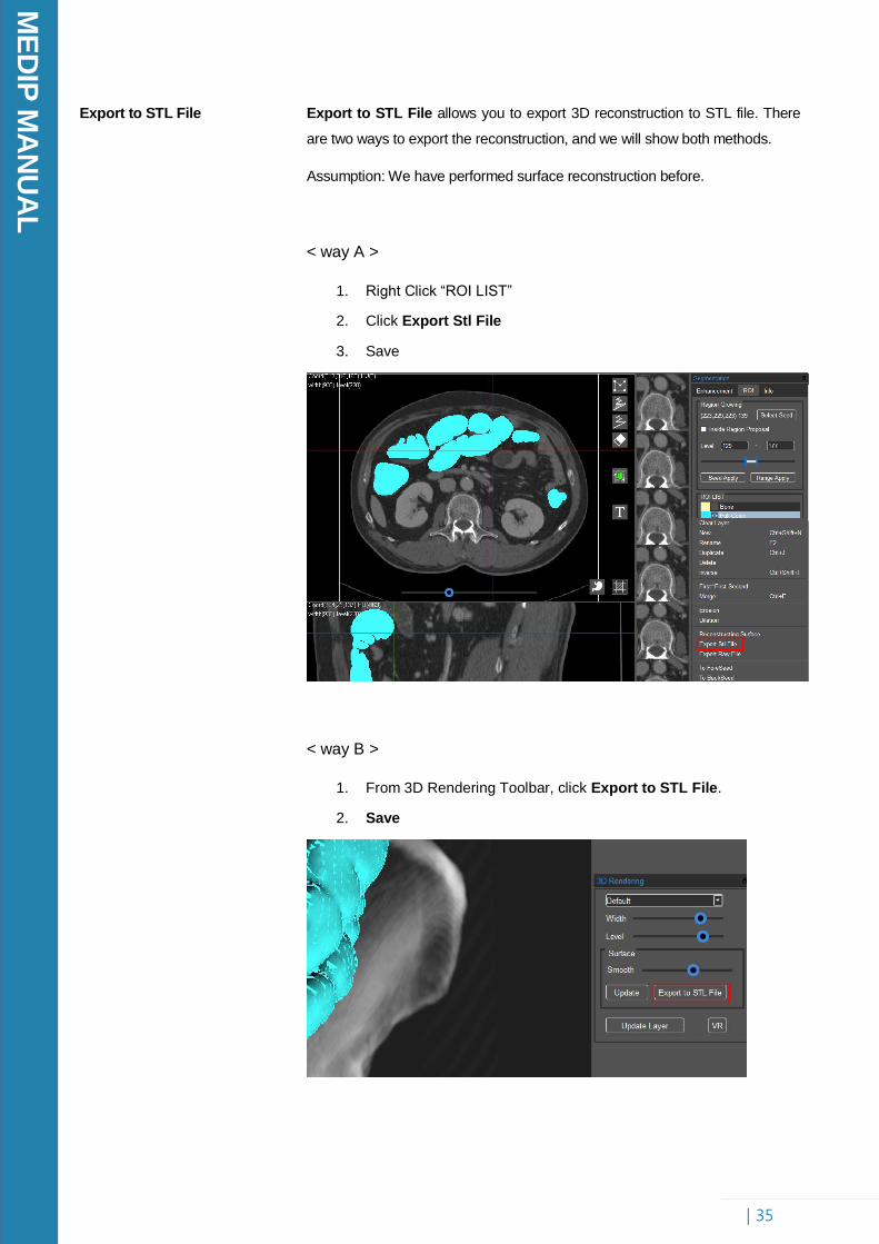
Export to STL File
Export to STL File allows you to export 3D reconstruction to STL file. There
are two ways to export the reconstruction, and we will show both methods.
Assumption: We have performed surface reconstruction before.
< way A >
1. Right Click “ROI LIST”
2. Click Export Stl File
3. Save
< way B >
1. From 3D Rendering Toolbar, click Export to STL File.
2. Save

ME
DIP
MA
NU
AL
| 36
Export to RAW File
Export to RAW File allows you to export 3D reconstruction to RAW file.
Assumption: We have performed surface reconstruction before.
1. Right Click “ROI LIST”, click Export Raw File
2. Save

ME
DIP
MA
NU
AL
| 37
7. Conclusion
Through the manual book, we have explored various functions of Medip
from installation to how to use. Medip also can be used for different type of
organs except for the mentioned above, such as lung, liver, and heart as
we have shown below. With Medip software, performing medical imaging
for segmentation, image enhancement, and 3D modeling is no longer
difficult. We provide comprehensive tools for these tasks which aim to
assist medical practices for easy and better visualization.
ME
DIP
MA
NU
AL
| 38
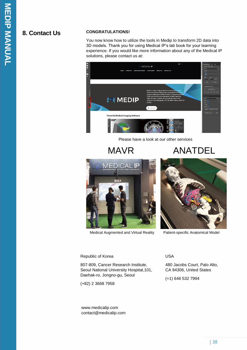
8. Contact Us
CONGRATULATIONS!
You now know how to utilize the tools in Medip to transform 2D data into
3D models. Thank you for using Medical IP’s lab book for your learning
experience. If you would like more information about any of the Medical IP
solutions, please contact us at:
Please have a look at our other services
Republic of Korea
807-809, Cancer Research Institute,
Seoul National University Hospital,101,
Daehak-ro, Jongno-gu, Seoul
(+82) 2 3668 7958
USA
480 Jacobs Court, Palo Alto,
CA 94306, United States
(+1) 646 532 7994
www.medicalip.com
MAVR ANATDEL
Medical Augmented and Virtual Reality Patient-specific Anatomical Model