copyright © 1997-2001 henning umland
TRANSCRIPT
Copyr ight © 1997-2001 Henning Umland
All Rights Reserved
Revised May 24, 2001
Legal Notice
1. L icense and Ownership
The archive file astro.zip is NOT public domain but rather is a licensed product. The file astro.zip,including its accompanying files, is owned and copyrighted by
Henning Umland, © Copyr ight 1997-2001, all r ights reserved. I grant the user a free nonexclusive license to download the file for personal or educational use aswell as for any lawful non-commercial purposes provided the terms of this agreement are met. Todeploy the archive file astro.zip and/or its contents in any commercial context, either in-house orexternally, you must obtain a license from the author.
2. Distr ibution
You may reproduce and freely distribute copies of the file astro.zip to third parties provided you donot do so for profit and each copy is unaltered and complete.
3. Warranty Disclaimer
I provide the file astro.zip and its contents to you "as is" without any express or implied warrantiesof any kind including, but not limited to, any implied warranties of fitness for a particular purpose. Imake no representations or warranties of any kind with respect to any support services I may renderto you. I do not warrant that the documents contained in the file astro.zip will meet yourrequirements or that they are error-free. You assume full responsibility for the selection, possession,and use of the documents and for verifying the results obtained therefrom.
May 24, 2001
Henning Umland
Correspondence address:
Dr. Henning UmlandRabenhorst 621244 Buchholz i. d. N.Germany
Fax +49 89 2443 66455E-mail [email protected]

Index
Preface
Chapter 1 The Elements of Celestial Navigation
Chapter 2 Altitude Measurement
Chapter 3 The Geographic Position of a Celestial Body
Chapter 4 Finding One's Position (Sight Reduction)
Chapter 5 Finding the Position of a Traveling Vessel
Chapter 6 Methods for Latitude and Longitude Measurement
Chapter 7 Finding Time and Longitude by Lunar Observations
Chapter 8 Rise, Set, Twilight
Chapter 9 Geodetic Aspects of Celestial Navigation
Chapter 10 Spherical Trigonometry
Chapter 11 The Navigational Triangle
Chapter 12 Other Navigational Formulas
Chapter 13 Mercator Charts and Plotting Sheets
Chapter 14 Magnetic Declination
Chapter 15 Ephemerides of the Sun
Chapter 16 Navigational Errors
Appendix
Legal Notice

Carpe diem. Horace
Preface
Why should anybody still use celestial navigation in the era of electronics and GPS? You might as well ask why somepeople still develop black and white photos in their darkroom instead of using a high-color digital camera and imageprocessing software. The answer would be the same: because it is a noble art, and because it is fun. Reading a GPSdisplay is easy and not very exciting as soon as you have got used to it. Celestial navigation, however, will always be achallenge because each scenario is different. Finding your geographic position by means of astronomical observationsrequires knowledge, judgement, and the ability to handle delicate instruments. In other words, you play an active partduring the whole process, and you have to use your brains. Everyone who ever reduced a sight knows the thrill I amtalking about. The way is the goal.It took centuries and generations of navigators, astronomers, geographers, mathematicians, and instrument makers todevelop the art and science of celestial navigation to its present state, and the knowledge thus accumulated is tooprecious to be forgotten. After all, celestial navigation will always be a valuable alternative if a GPS receiver happens tofail.Yearsago, when I read my first book on navigation, the chapter on celestial navigation with its fascinating diagrams andformulas immediately caught my particular interest although I was a little deterred by its complexity at first. As I becamemore advanced, I realized that celestial navigation isnot as difficult as it seems to be at first glance. Further, I found thatmany publications on this subject, although packed with information, are more confusing than enlightening, probablybecause most of them have been written by experts and for experts.I decided to write something like a compact guide-book for my personal use which had to include operating instructionsas well as all important formulas and diagrams. The idea to publish it came in 1997 when I became interested in theinternet and found that it is the ideal medium to share one's knowledge with others. I took my manuscript, rewrote it inthe form of a structured manual, and redesigned the layout to make it more attractive to the public. After convertingeverything to the HTML format, I published it on my web site. Since then, I have revised text and graphic imagesseveral times and added a couple of new chapters. People seem to like it, at least I get approving e-mails now and then.
Following the recent trend, I decided to convert the manual to the PDF format, which has become an establishedstandard for internet publishing. In contrast to HTML documents, the page-oriented PDF documents retain their layoutwhen printed. The HTML version is no longer available since keeping two versions in different formats synchronizedwas too much work. In my opinion, a printed manual is more useful anyway.
Since people keep asking me how I wrote the documents and how I created the graphic images, a short description ofthe procedure and software used is given below:
Drawings and diagrams were made with good old CorelDraw! 3.0 and exported as GIF files.
The manual was designed and written with Star Office. The Star Office (.sdw) documents were then converted toPostscript (.ps) files with the AdobePS printer driver (available at www.adobe.com). Finally, the Postscript files wereconverted to PDF files with GsView and Ghostscript (www.ghostscript.com).
I apologize for misspellings, grammar errors, and wrong punctuation. I did my best, but after all, English is not mynative language.I hope the new version will find as many readers as the old one. Hints and suggestions are always welcome. Since I amvery busy, I may not always be able to answer incoming e-mails immediately. Be patient.Last but not least, I owe my wife an apology for spending countless hours in front of the PC, staying up late, neglectinghousehold chores, etc. I'll try to mend my ways. Some day ...
May 24, 2001
Henning Umland
Correspondence address:
Dr. Henning UmlandRabenhorst 621244 Buchholz i. d. N.Germany
Fax +49 89 2443 66455E-mail [email protected]
Chapter 1
The Elements of Celestial Navigation
Celestial navigation, a branch of applied astronomy, is the art and science of finding one's geographic position throughastronomical observations, particularly by measuring altitudes of celestial bodies – sun, moon, planets, or stars.
An observer watching the night sky without knowing anything about geography and astronomy might spontaneously getthe impression of being on a plane located at the center of a huge, hollow sphere with the celestial bodies attached to itsinner surface. Indeed, this naive model of the universe was in use for millennia and developed to a high degree ofperfection by ancient astronomers. Still today, it is a useful tool for celestial navigation since the navigator, like theastronomers of old, measures apparent positions of bodies in the sky but not their absolute positions in space.
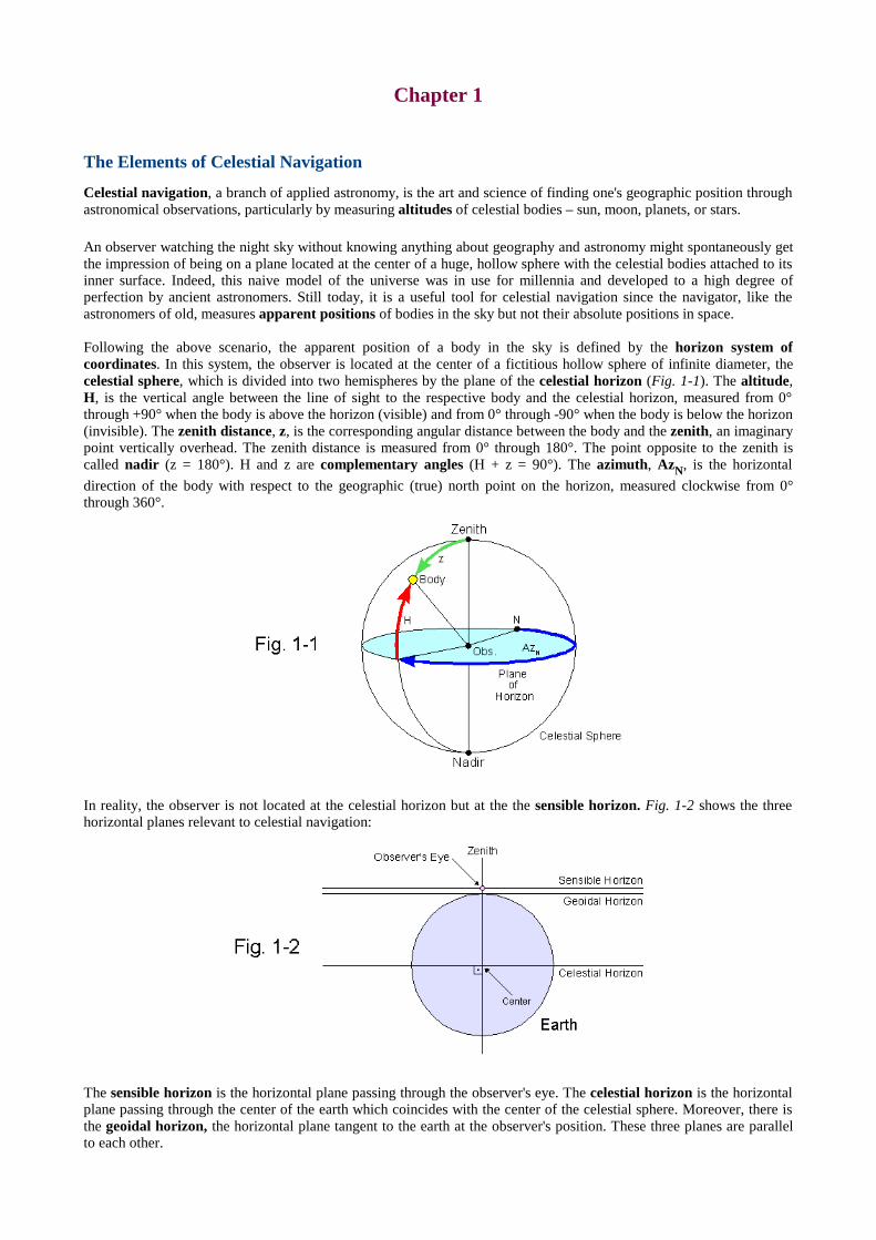
Following the above scenario, the apparent position of a body in the sky is defined by the horizon system ofcoordinates. In this system, the observer is located at the center of a fictitious hollow sphere of infinite diameter, thecelestial sphere, which is divided into two hemispheres by the plane of the celestial horizon (Fig. 1-1). The altitude,H, is the vertical angle between the line of sight to the respective body and the celestial horizon, measured from 0°through +90° when the body isabove the horizon (visible) and from 0° through -90° when the body isbelow the horizon(invisible). The zenith distance, z, is the corresponding angular distance between the body and the zenith, an imaginarypoint vertically overhead. The zenith distance is measured from 0° through 180°. The point opposite to the zenith iscalled nadir (z = 180°). H and z are complementary angles (H + z = 90°). The azimuth, AzN, is the horizontal
direction of the body with respect to the geographic (true) north point on the horizon, measured clockwise from 0°through 360°.
In reality, the observer is not located at the celestial horizon but at the the sensible horizon. Fig. 1-2 shows the threehorizontal planes relevant to celestial navigation:
The sensible horizon is the horizontal plane passing through the observer's eye. The celestial horizon is the horizontalplane passing through the center of the earth which coincides with the center of the celestial sphere. Moreover, there isthe geoidal horizon, the horizontal plane tangent to the earth at the observer's position. These three planes are parallelto each other.
The sensible horizon merges into the geoidal horizon when the observer's eye is at sea or ground level. Since bothhorizonsare usually very close to each other, they can be considered as identical under practical conditions. None of theabove horizontal planes coincides with the visible horizon, the line where the earth's surface and the sky appear to meet.
Calculations of celestial navigation always refer to the geocentric altitude of a body, the altitude with respect to afictitious observer being at the celestial horizon and at the center of the earth which coincides the center of thecelestial sphere. Since there is no way to measure this altitude directly, it has to be derived from the altitude withrespect to the visible or sensible horizon (altitude corrections, chapter 2).
A marine sextant is an instrument designed to measure the altitude of a body with reference to the visible sea horizon.Instruments with any kind of an artificial horizon measure the altitude referring to the sensible horizon (chapter 2).
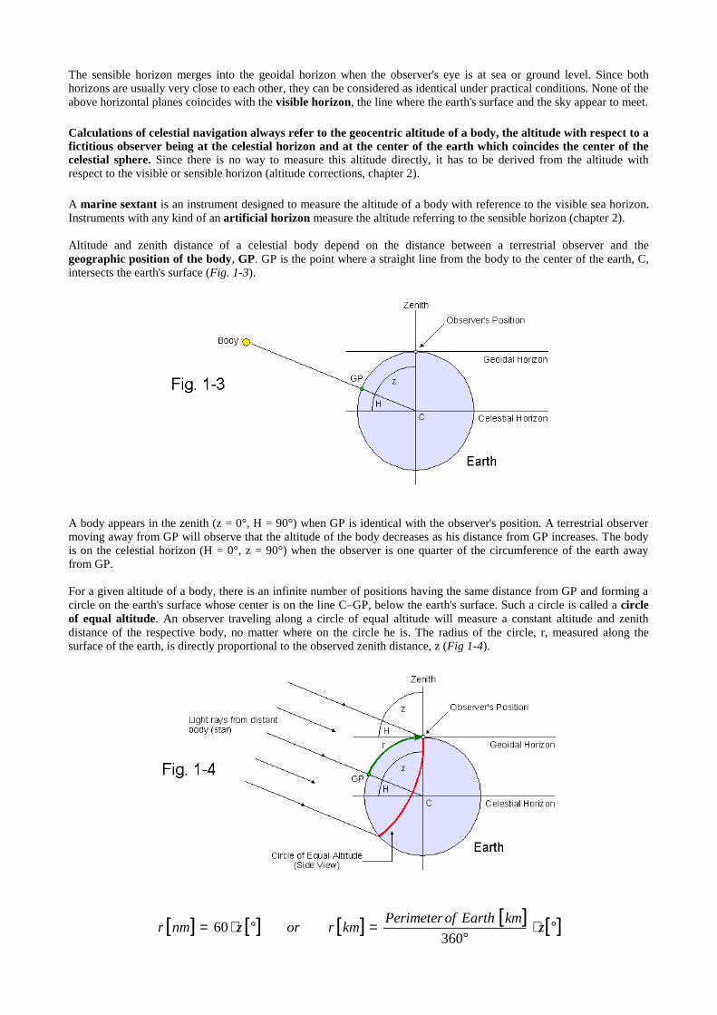
Altitude and zenith distance of a celestial body depend on the distance between a terrestrial observer and thegeographic position of the body, GP. GP is the point where a straight line from the body to the center of the earth, C,intersects the earth's surface (Fig. 1-3).
A body appears in the zenith (z = 0°, H = 90°) when GP is identical with the observer's position. A terrestrial observermoving away from GP will observe that the altitude of the body decreases as his distance from GP increases. The bodyis on the celestial horizon (H = 0°, z = 90°) when the observer is one quarter of the circumference of the earth awayfrom GP.
For a given altitude of a body, there is an infinite number of positions having the same distance from GP and forming acircle on the earth's surface whose center is on the line C–GP, below the earth's surface. Such a circle is called a circleof equal altitude. An observer traveling along a circle of equal altitude will measure a constant altitude and zenithdistance of the respective body, no matter where on the circle he is. The radius of the circle, r, measured along thesurface of the earth, is directly proportional to the observed zenith distance, z (Fig 1-4).
[ ] [ ] [ ] [ ] [ ]°⋅°
=°⋅= zkmEarthofPerimeter
kmrorznmr360
60
One nautical mile (1 nm = 1.852 km) is the great circle distance of one minute of arc (the definition of a great circle isgiven in chapter 3). The mean perimeter of the earth is 40031.6 km.
Light rays coming from distant objects (stars) are virtually parallel to each other when reaching the earth. Therefore, thealtitude with respect to the geoidal (sensible) horizon equals the altitude with respect to the celestial horizon. In contrast,light rays coming from the relatively close bodies of the solar system are diverging. This results in a measurabledifference between both altitudes (parallax). The effect is greatest when observing the moon, the body closest to theearth (see chapter 2, Fig. 2-4).
The azimuth of a body depends on the observer's position on the circle of equal altitude and can assume any valuebetween 0° and 360°.
Whenever we measure the altitude or zenith distance of a celestial body, we have already gained partial informationabout our own geographic position because we know we are somewhere on a circle of equal altitude with the radius rand the center GP, the geographic position of the body. Of course, the information available so far is still incompletebecause we could be anywhere on the circle of equal altitude which comprises an infinite number of possible positionsand is therefore also called a circle of position (see chapter 4).
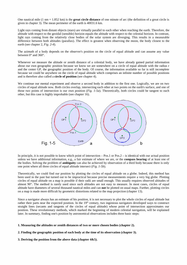
We continue our mental experiment and observe a second body in addition to the first one. Logically, we are on twocirclesof equal altitude now. Both circlesoverlap, intersecting each other at two pointson the earth's surface, and one ofthose two points of intersection is our own position (Fig. 1-5a). Theoretically, both circles could be tangent to eachother, but this case is highly improbable (see chapter 16).
In principle, it is not possible to know which point of intersection – Pos.1 or Pos.2 – is identical with our actual positionunless we have additional information, e.g., a fair estimate of where we are, or the compass bearing of at least one ofthe bodies. Solving the problem of ambiguity can also be achieved by observation of a third body because there is onlyone point where all three circles of equal altitude intersect (Fig. 1-5b).
Theoretically, we could find our position by plotting the circles of equal altitude on a globe. Indeed, this method hasbeen used in the past but turned out to be impractical because precise measurements require a very big globe. Plottingcircles of equal altitude on a map is possible if their radii are small enough. This usually requires observed altitudes ofalmost 90°. The method is rarely used since such altitudes are not easy to measure. In most cases, circles of equalaltitude have diameters of several thousand nautical milesand can not be plotted on usual maps. Further, plotting circleson a map is made more difficult by geometric distortions related to the map projection (chapter 13).
Since a navigator always has an estimate of his position, it is not necessary to plot the whole circles of equal altitude butrather their parts near the expected position. In the 19th century, two ingenious navigators developed ways to constructstraight lines (secants and tangents of the circles of equal altitude) whose point of intersection approximates ourposition. These revolutionary methods, which marked the beginning of modern celestial navigation, will be explainedlater. In summary, finding one's position by astronomical observations includes three basic steps:
1. Measuring the altitudes or zenith distances of two or more chosen bodies (chapter 2).
2. Finding the geographic position of each body at the time of its observation (chapter 3).
3. Deriving the position from the above data (chapter 4&5).
Chapter 2
Altitude Measurement
Although altitudes and zenith distances are equally suitable for navigational calculations, most formulas are traditionallybased upon altitudes which are easily accessible using the visible sea horizon as a natural reference line. Directmeasurement of the zenith distance, however, requires an instrument with an artificial horizon, e.g., a pendulum or spiritlevel indicating the direction of the normal force (perpendicular to the local horizontal plane), since a reference point inthe sky does not exist.
Instruments
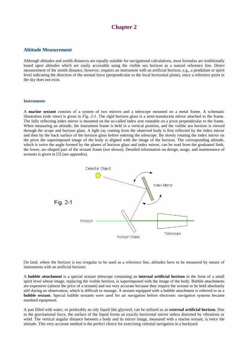
A marine sextant consists of a system of two mirrors and a telescope mounted on a metal frame. A schematicillustration (side view) is given in Fig. 2-1. The rigid horizon glass is a semi-translucent mirror attached to the frame.The fully reflecting index mirror is mounted on the so-called index arm rotatable on a pivot perpendicular to the frame.When measuring an altitude, the instrument frame is held in a vertical position, and the visible sea horizon is viewedthrough the scope and horizon glass. A light ray coming from the observed body is first reflected by the index mirrorand then by the back surface of the horizon glass before entering the telescope. By slowly rotating the index mirror onthe pivot the superimposed image of the body is aligned with the image of the horizon. The corresponding altitude,which is twice the angle formed by the planes of horizon glass and index mirror, can be read from the graduated limb,the lower, arc-shaped part of the sextant frame (not shown). Detailed information on design, usage, and maintenance ofsextants is given in [3] (see appendix).
On land, where the horizon is too irregular to be used as a reference line, altitudes have to be measured by means ofinstruments with an artificial horizon:
A bubble attachment is a special sextant telescope containing an internal artificial horizon in the form of a smallspirit level whose image, replacing the visible horizon, is superimposed with the image of the body. Bubble attachmentsare expensive (almost the price of a sextant) and not very accurate because they require the sextant to be held absolutelystill during an observation, which is difficult to manage. A sextant equipped with a bubble attachment is referred to as abubble sextant. Special bubble sextants were used for air navigation before electronic navigation systems becamestandard equipment.
A pan filled with water, or preferably an oily liquid like glycerol, can be utilized as an external artificial horizon. Dueto the gravitational force, the surface of the liquid forms an exactly horizontal mirror unless distorted by vibrations orwind. The vertical angular distance between a body and its mirror image, measured with a marine sextant, is twice thealtitude. This very accurate method is the perfect choice for exercising celestial navigation in a backyard.
A theodolite is basically a telescopic sight which can be rotated about a vertical and a horizontal axis. The angle ofelevation is read from the vertical circle, the horizontal direction from the horizontal circle. Built-in spirit levels are usedto align the instrument with the plane of the sensible horizon before starting the observations (artificial horizon).Theodolites are primarily used for surveying, but they are excellent navigation instruments as well. Many models canmeasure angles to 0.1' which cannot be achieved even with the best sextants. A theodolite is mounted on a tripod and hasto stand on solid ground. Therefore, it is restricted to land navigation. Traditionally, theodolites measure zenithdistances. Modern models can optionally measure altitudes.
Never view the sun through an optical instrument without inserting a proper shade glass, otherwise your eyemight suffer permanent damage !
Altitude corrections
Any altitude measured with a sextant or theodolite contains errors. Altitude corrections are necessary toeliminate systematic altitude errors and to reduce the altitude measured relative to the visible or sensible horizonto the altitude with respect to the celestial horizon and the center of the earth (chapter 1). Of course, altitudecorrections do not remove random errors.
Index error (IE)
A sextant or theodolite, unless recently calibrated, usually has a constant error (index error, IE) which has to besubtracted from the readings before they can be processed further. The error is positive if the displayed value is greaterthan the actual value and negative if the displayed value is smaller. Angle-dependent errors require alignment of theinstrument or the use of an individual correction table.
The sextant altitude, Hs, is the altitude as indicated by the sextant before any corrections have been applied.
When using an external artificial horizon, H1 (not Hs!) has to be divided by two.
A theodolite measuring the zenith distance, z, requires the following formula to obtain H1:
Dip of horizon
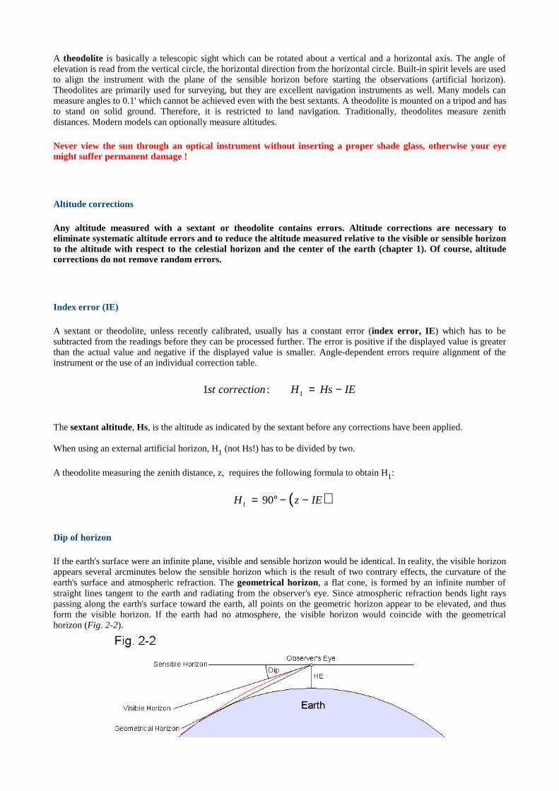
If the earth's surface were an infinite plane, visible and sensible horizon would be identical. In reality, the visible horizonappears several arcminutes below the sensible horizon which is the result of two contrary effects, the curvature of theearth's surface and atmospheric refraction. The geometrical horizon, a flat cone, is formed by an infinite number ofstraight lines tangent to the earth and radiating from the observer's eye. Since atmospheric refraction bends light rayspassing along the earth's surface toward the earth, all points on the geometric horizon appear to be elevated, and thusform the visible horizon. If the earth had no atmosphere, the visible horizon would coincide with the geometricalhorizon (Fig. 2-2).
IEHsHcorrectionst −=1:1
( )IEzH −−°= 901
The altitude of the sensible horizon relative to the visible horizon is called dip and is a function of the height of eye,HE, the vertical distance of the observer's eye from the earth's surface:
The above formula is empirical and includes the effects of the curvature of the earth's surface and atmosphericrefraction*.
*At sea, the dip of horizon can be obtained directly by measuring the vertical angle between the visible horizon in front of the observer and thevisible horizon behind the observer (through the zenith). Subtracting 180° from the angle thus measured and dividing the resulting angle by twoyields the dip of horizon. This very accurate method is rarely used because it requires a special instrument (similar to a sextant).
The correction for dip has to be omitted (dip = 0) if any kind of an ar tificial hor izon is used since an ar tificialhor izon indicates the sensible hor izon.
The altitude obtained after applying corrections for index error and dip is also referred to as apparent altitude, Ha.
Atmospher ic refraction
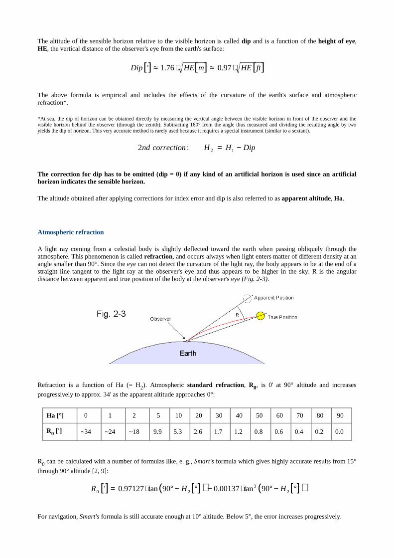
A light ray coming from a celestial body is slightly deflected toward the earth when passing obliquely through theatmosphere. Thisphenomenon is called refraction, and occurs always when light entersmatter of different density at anangle smaller than 90°. Since the eye can not detect the curvature of the light ray, the body appears to be at the end of astraight line tangent to the light ray at the observer's eye and thus appears to be higher in the sky. R is the angulardistance between apparent and true position of the body at the observer's eye (Fig. 2-3).
Refraction is a function of Ha (= H2). Atmospheric standard refraction, R0, is 0' at 90° altitude and increases
progressively to approx. 34' as the apparent altitude approaches 0°:
Ha [°] 0 1 2 5 10 20 30 40 50 60 70 80 90
R0 [' ] ~34 ~24 ~18 9.9 5.3 2.6 1.7 1.2 0.8 0.6 0.4 0.2 0.0
R0 can be calculated with a number of formulas like, e. g., Smart's formula which gives highly accurate results from 15°
through 90° altitude [2, 9]:
For navigation, Smart's formula is still accurate enough at 10° altitude. Below 5°, the error increases progressively.
[ ] [ ] [ ]ftHEmHEDip ⋅≈⋅≈ 97.076.1'
DipHHcorrectionnd −= 12:2
[ ] [ ]( ) [ ]( )°−°⋅−°−°⋅= 23
20 90tan00137.090tan97127.0' HHR
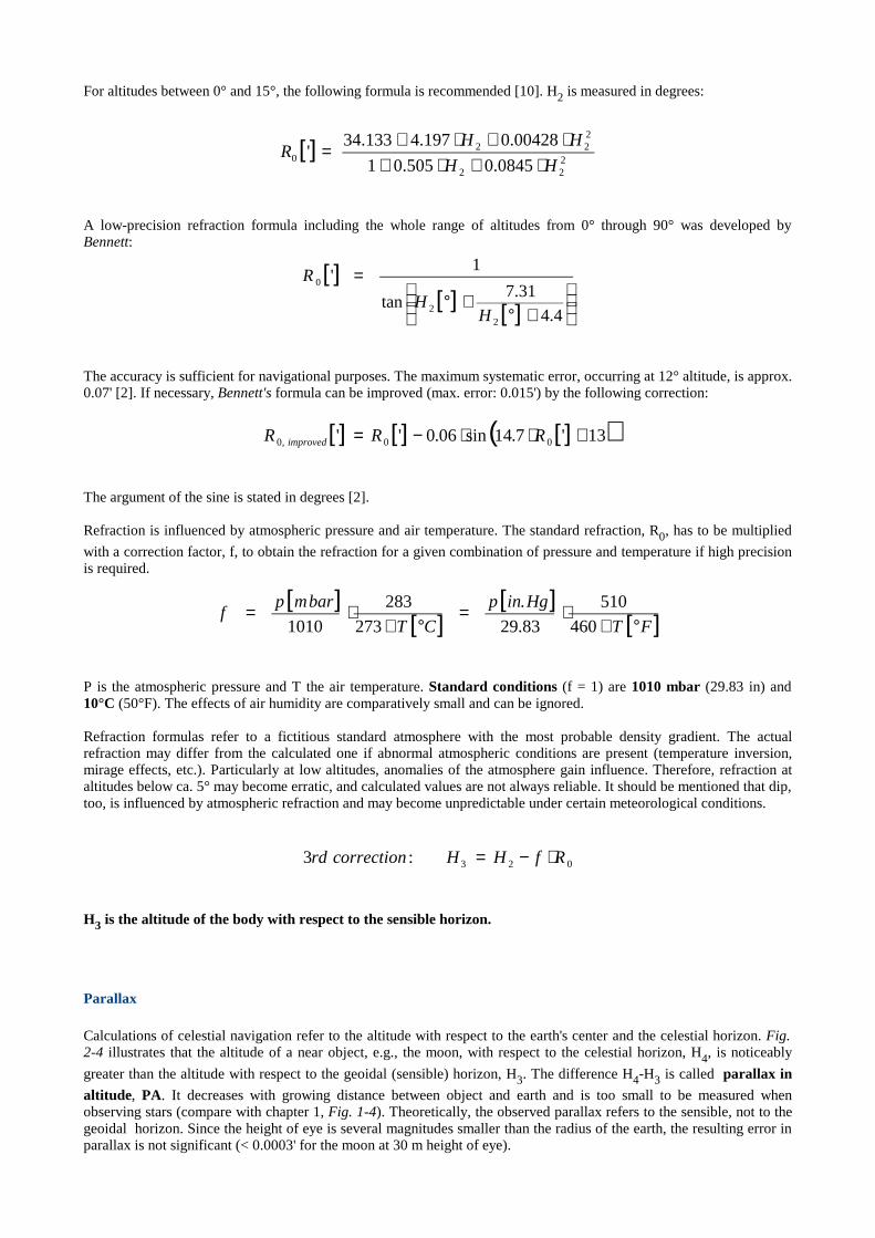
For altitudes between 0° and 15°, the following formula is recommended [10]. H2 is measured in degrees:
A low-precision refraction formula including the whole range of altitudes from 0° through 90° was developed byBennett:
The accuracy is sufficient for navigational purposes. The maximum systematic error, occurring at 12° altitude, is approx.0.07' [2]. If necessary, Bennett's formula can be improved (max. error: 0.015') by the following correction:
The argument of the sine is stated in degrees [2].
Refraction is influenced by atmospheric pressure and air temperature. The standard refraction, R0, has to be multiplied
with a correction factor, f, to obtain the refraction for a given combination of pressure and temperature if high precisionis required.
P is the atmospheric pressure and T the air temperature. Standard conditions (f = 1) are 1010 mbar (29.83 in) and10°C (50°F). The effects of air humidity are comparatively small and can be ignored.
Refraction formulas refer to a fictitious standard atmosphere with the most probable density gradient. The actualrefraction may differ from the calculated one if abnormal atmospheric conditions are present (temperature inversion,mirage effects, etc.). Particularly at low altitudes, anomalies of the atmosphere gain influence. Therefore, refraction ataltitudes below ca. 5° may become erratic, and calculated values are not always reliable. It should be mentioned that dip,too, is influenced by atmospheric refraction and may become unpredictable under certain meteorological conditions.
H3 is the altitude of the body with respect to the sensible hor izon.
Parallax
Calculations of celestial navigation refer to the altitude with respect to the earth's center and the celestial horizon. Fig.2-4 illustrates that the altitude of a near object, e.g., the moon, with respect to the celestial horizon, H4, is noticeably
greater than the altitude with respect to the geoidal (sensible) horizon, H3. The difference H4-H3 is called parallax in
altitude, PA. It decreases with growing distance between object and earth and is too small to be measured whenobserving stars (compare with chapter 1, Fig. 1-4). Theoretically, the observed parallax refers to the sensible, not to thegeoidal horizon. Since the height of eye is several magnitudes smaller than the radius of the earth, the resulting error inparallax is not significant (< 0.0003' for the moon at 30 m height of eye).
[ ]222
222
0 0845.0505.01
00428.0197.4133.34'
HH
HHR
⋅+⋅+⋅+⋅+
=
[ ][ ] [ ]
+°
+°=
4.4
31.7tan
1'
22
0
HH
R
[ ] [ ] [ ]( )13'7.14sin06.0'' 00,0 +⋅⋅−= RRR improved
[ ][ ]
[ ][ ]FT
Hginp
CT
barmpf
°+⋅=
°+⋅=
460
510
83.29
.
273
283
1010
023:3 RfHHcorrectionrd ⋅−=

The parallax (in altitude) of a body being on the geoidal horizon is called horizontal parallax, HP. The HP of the sunis approx. 0.15'. Current HP's of the moon (ca. 1°!) and the navigational planets are given in the Nautical Almanac[12] and similar publications, e.g., [13]. PA is a function of altitude and HP of a body:
When we observe the upper or lower limb of a body (see below), we assume that the parallax of the limb equals theparallax of the center (when at the same altitude). For geometric reasons (curvature of the surface), this is not quitecorrect. However, even with the moon, the body with by far the greatest parallax, the resulting error is so small that itcan be ignored (<< 1'').
The above formula is rigorous for a spherical earth. However, the earth is not exactly a sphere but resembles an oblatespheroid, a sphere flattened at the poles (chapter 9). This may cause a small but measurable error in the parallax of themoon (≤ 0.2'), depending on the observer's position [12]. Therefore, a small correction, OB, should be added to PA ifhigh precision is required:
Lat is the observer's assumed latitude (chapter 4). AzN , the azimuth of the moon, is either measured with a compass
(compass bearing) or calculated using the formulas given in chapter 4.
Semidiameter
When observing sun or moon with a marine sextant or theodolite, it is not possible to locate the center of the body withsufficient accuracy. It is therefore common practice to measure the altitude of the upper or lower limb of the body andadd or subtract the apparent semidiameter, SD, the angular distance of the respective limb from the center (Fig. 2-5).
( ) 33 coscossinarcsin HHPHHPPA ⋅≈⋅=
( )[ ]32
3 cossinsincos2sin298
HLatHAzLatHP
OB N ⋅−⋅⋅⋅⋅=
OBPAPA improved +=
PAHHcorrectionth += 34:4
We correct for the geocentric SD, the SD measured by a fictitiousobserver at the center the earth, since H4 refers to the
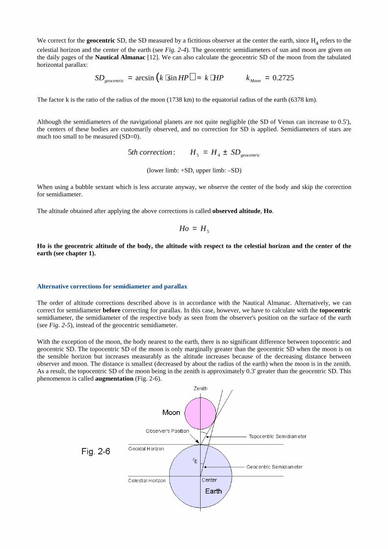
celestial horizon and the center of the earth (see Fig. 2-4). The geocentric semidiameters of sun and moon are given onthe daily pages of the Nautical Almanac [12]. We can also calculate the geocentric SD of the moon from the tabulatedhorizontal parallax:
The factor k is the ratio of the radius of the moon (1738 km) to the equatorial radius of the earth (6378 km).
Although the semidiameters of the navigational planets are not quite negligible (the SD of Venus can increase to 0.5'),the centers of these bodies are customarily observed, and no correction for SD is applied. Semidiameters of stars aremuch too small to be measured (SD=0).
(lower limb: +SD, upper limb: –SD)
When using a bubble sextant which is less accurate anyway, we observe the center of the body and skip the correctionfor semidiameter.
The altitude obtained after applying the above corrections is called observed altitude, Ho.
Ho is the geocentric altitude of the body, the altitude with respect to the celestial horizon and the center of theearth (see chapter 1).
Alternative corrections for semidiameter and parallax
The order of altitude corrections described above is in accordance with the Nautical Almanac. Alternatively, we cancorrect for semidiameter before correcting for parallax. In this case, however, we have to calculate with the topocentricsemidiameter, the semidiameter of the respective body as seen from the observer's position on the surface of the earth(see Fig. 2-5), instead of the geocentric semidiameter.
With the exception of the moon, the body nearest to the earth, there is no significant difference between topocentric andgeocentric SD. The topocentric SD of the moon is only marginally greater than the geocentric SD when the moon is onthe sensible horizon but increases measurably as the altitude increases because of the decreasing distance betweenobserver and moon. The distance is smallest (decreased by about the radius of the earth) when the moon is in the zenith.As a result, the topocentric SD of the moon being in the zenith is approximately 0.3' greater than the geocentric SD. Thisphenomenon is called augmentation (Fig. 2-6).
( ) 2725.0sinarcsin =⋅≈⋅= Moongeocentric kHPkHPkSD
geocentricSDHHcorrectionth ±= 45:5
5HHo =
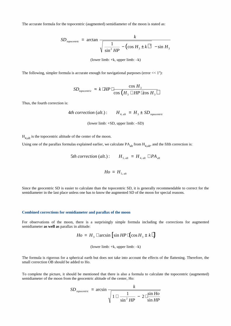
The accurate formula for the topocentric (augmented) semidiameter of the moon is stated as:
(lower limb: +k, upper limb: –k)
The following, simpler formula is accurate enough for navigational purposes (error << 1''):
Thus, the fourth correction is:
(lower limb: +SD, upper limb: –SD)
H4,alt is the topocentric altitude of the center of the moon.
Using one of the parallax formulas explained earlier, we calculate PAalt from H4,alt, and the fifth correction is:
Since the geocentric SD is easier to calculate than the topocentric SD, it is generally recommendable to correct for thesemidiameter in the last place unless one has to know the augmented SD of the moon for special reasons.
Combined corrections for semidiameter and parallax of the moon
For observations of the moon, there is a surprisingly simple formula including the corrections for augmentedsemidiameter as well as parallax in altitude:
(lower limb: +k, upper limb: –k)
The formula is rigorous for a spherical earth but does not take into account the effects of the flattening. Therefore, thesmall correction OB should be added to Ho.
To complete the picture, it should be mentioned that there is also a formula to calculate the topocentric (augmented)semidiameter of the moon from the geocentric altitude of the center, Ho:
( ) 32
32sincos
sin
1arctan
HkHHP
kSD ctopocentri
−±−=
ctopocentrialt SDHHaltcorrectionth ±= 3,4:.)(4
altaltalt PAHHaltcorrectionth += ,4,5:.)(5
altHHo ,5=
( )[ ]kHHPHHo ±⋅+= 33 cossinarcsin
HP
Ho
HP
kSD ctopocentri
sin
sin2
sin
11
arcsin
2⋅−+
=
( )33
3
coscos
cos
HHPH
HHPkSD ctopocentri ⋅+
⋅⋅≈
Phase correction (Venus and Mars)
Since Venus and Mars show phases similar to the moon, their apparent center may differ somewhat from the actualcenter. Since the coordinates of both planets tabulated in the Nautical Almanac [12] refer to the apparent center, anadditional correction is not required. The phase correction for Jupiter and Saturn is too small to be significant.
In contrast, coordinates calculated with Interactive Computer Ephemeris refer to the actual center. In this case, theupper or lower limb of the respective planet should be observed if the magnification of the telescope permits it.
The Nautical Almanac provides sextant altitude correction tables for sun, planets, stars (pages A2 – A4), and the moon(pages xxxiv – xxxv), which can be used instead of the above formulas if very high precision is not required (the tablescause additional rounding errors). Instruments with an artificial horizon can exhibit additional errors caused by acceleration forces acting on the bubble orpendulum and preventing it from aligning itself with the direction of the gravitational force. Such acceleration forces canbe random (vessel movements) or systematic (coriolis force). The coriolis force is important to air navigation andrequires a special correction formula. In the vicinity of mountains, ore deposits, and other local irregularities of theearth's crust, the gravitational force itself can be slightly deflected from its normal direction.
Chapter 3
The Geographic Position (GP) of a Celestial Body
Geographic terms
In celestial navigation, the earth is regarded as a sphere. Although this is only an approximation, the geometry of thesphere is applied successfully, and the errors caused by the oblateness of the earth are usually negligible (see chapter 9).
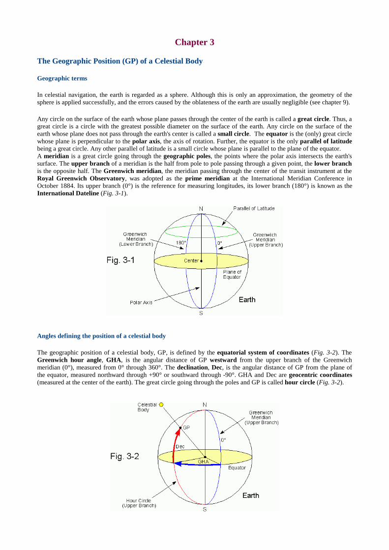
Any circle on the surface of the earth whose plane passes through the center of the earth is called a great circle. Thus, agreat circle is a circle with the greatest possible diameter on the surface of the earth. Any circle on the surface of theearth whose plane doesnot pass through the earth's center is called a small circle. The equator is the (only) great circlewhose plane is perpendicular to the polar axis, the axis of rotation. Further, the equator is the only parallel of latitudebeing a great circle. Any other parallel of latitude is a small circle whose plane is parallel to the plane of the equator. A meridian is a great circle going through the geographic poles, the points where the polar axis intersects the earth'ssurface. The upper branch of a meridian is the half from pole to pole passing through a given point, the lower branchis the opposite half. The Greenwich meridian, the meridian passing through the center of the transit instrument at theRoyal Greenwich Observatory, was adopted as the prime meridian at the International Meridian Conference inOctober 1884. Its upper branch (0°) is the reference for measuring longitudes, its lower branch (180°) is known as theInternational Dateline (Fig. 3-1).
Angles defining the position of a celestial body
The geographic position of a celestial body, GP, is defined by the equatorial system of coordinates (Fig. 3-2). TheGreenwich hour angle, GHA, is the angular distance of GP westward from the upper branch of the Greenwichmeridian (0°), measured from 0° through 360°. The declination, Dec, is the angular distance of GP from the plane ofthe equator, measured northward through +90° or southward through -90°. GHA and Dec are geocentric coordinates(measured at the center of the earth). The great circle going through the poles and GP is called hour circle (Fig. 3-2).
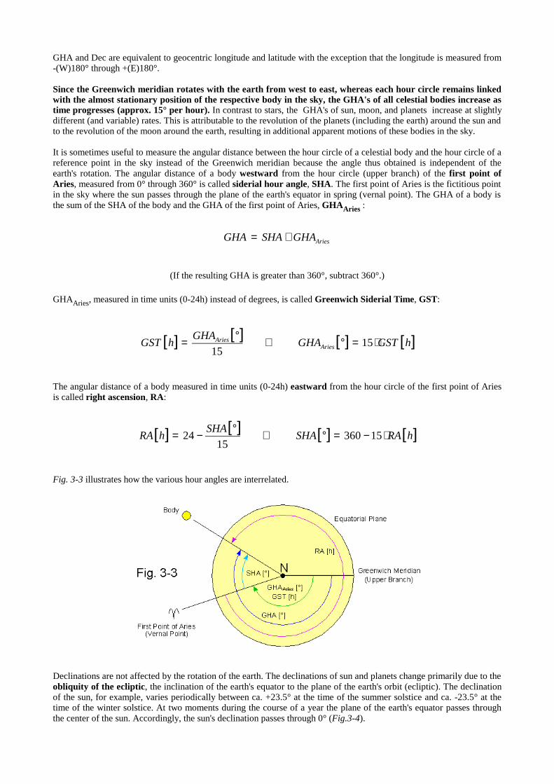
GHA and Dec are equivalent to geocentric longitude and latitude with the exception that the longitude is measured from-(W)180° through +(E)180°.
Since the Greenwich mer idian rotates with the ear th from west to east, whereas each hour circle remains linkedwith the almost stationary position of the respective body in the sky, the GHA's of all celestial bodies increase astime progresses (approx. 15° per hour). In contrast to stars, the GHA's of sun, moon, and planets increase at slightlydifferent (and variable) rates. This isattributable to the revolution of the planets (including the earth) around the sun andto the revolution of the moon around the earth, resulting in additional apparent motions of these bodies in the sky.
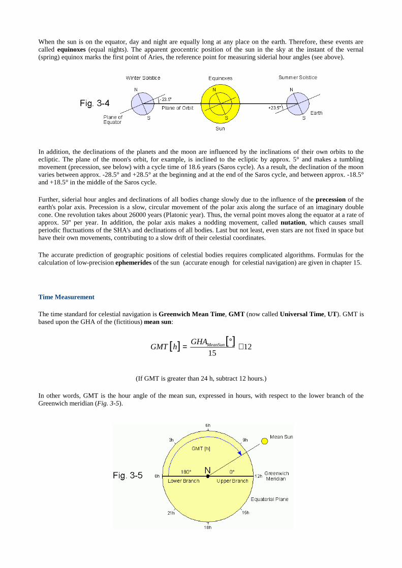
It is sometimes useful to measure the angular distance between the hour circle of a celestial body and the hour circle of areference point in the sky instead of the Greenwich meridian because the angle thus obtained is independent of theearth's rotation. The angular distance of a body westward from the hour circle (upper branch) of the first point ofAr ies, measured from 0° through 360° iscalled sider ial hour angle, SHA. The first point of Aries is the fictitious pointin the sky where the sun passes through the plane of the earth's equator in spring (vernal point). The GHA of a body isthe sum of the SHA of the body and the GHA of the first point of Aries, GHAAr ies :
(If the resulting GHA is greater than 360°, subtract 360°.)
GHAAries, measured in time units (0-24h) instead of degrees, is called Greenwich Sider ial Time, GST:
The angular distance of a body measured in time units (0-24h) eastward from the hour circle of the first point of Ariesis called r ight ascension, RA:
Fig. 3-3 illustrates how the various hour angles are interrelated.
Declinations are not affected by the rotation of the earth. The declinations of sun and planets change primarily due to theobliquity of the ecliptic, the inclination of the earth's equator to the plane of the earth's orbit (ecliptic). The declinationof the sun, for example, varies periodically between ca. +23.5° at the time of the summer solstice and ca. -23.5° at thetime of the winter solstice. At two moments during the course of a year the plane of the earth's equator passes throughthe center of the sun. Accordingly, the sun's declination passes through 0° (Fig.3-4).
AriesGHASHAGHA +=
[ ] [ ] [ ] [ ]hGSTGHAGHA
hGST AriesAries ⋅=°⇔°= 15
15
[ ] [ ] [ ] [ ]hRASHASHA
hRA ⋅−=°⇔°−= 1536015
24
When the sun is on the equator, day and night are equally long at any place on the earth. Therefore, these events arecalled equinoxes (equal nights). The apparent geocentric position of the sun in the sky at the instant of the vernal(spring) equinox marks the first point of Aries, the reference point for measuring siderial hour angles (see above).
In addition, the declinations of the planets and the moon are influenced by the inclinations of their own orbits to theecliptic. The plane of the moon's orbit, for example, is inclined to the ecliptic by approx. 5° and makes a tumblingmovement (precession, see below) with a cycle time of 18.6 years (Saros cycle). Asa result, the declination of the moonvaries between approx. -28.5° and +28.5° at the beginning and at the end of the Saros cycle, and between approx. -18.5°and +18.5° in the middle of the Saros cycle.
Further, siderial hour angles and declinations of all bodies change slowly due to the influence of the precession of theearth's polar axis. Precession is a slow, circular movement of the polar axis along the surface of an imaginary doublecone. One revolution takes about 26000 years (Platonic year). Thus, the vernal point moves along the equator at a rate ofapprox. 50'' per year. In addition, the polar axis makes a nodding movement, called nutation, which causes smallperiodic fluctuations of the SHA's and declinations of all bodies. Last but not least, even stars are not fixed in space buthave their own movements, contributing to a slow drift of their celestial coordinates.
The accurate prediction of geographic positions of celestial bodies requires complicated algorithms. Formulas for thecalculation of low-precision ephemerides of the sun (accurate enough for celestial navigation) are given in chapter 15.
Time Measurement
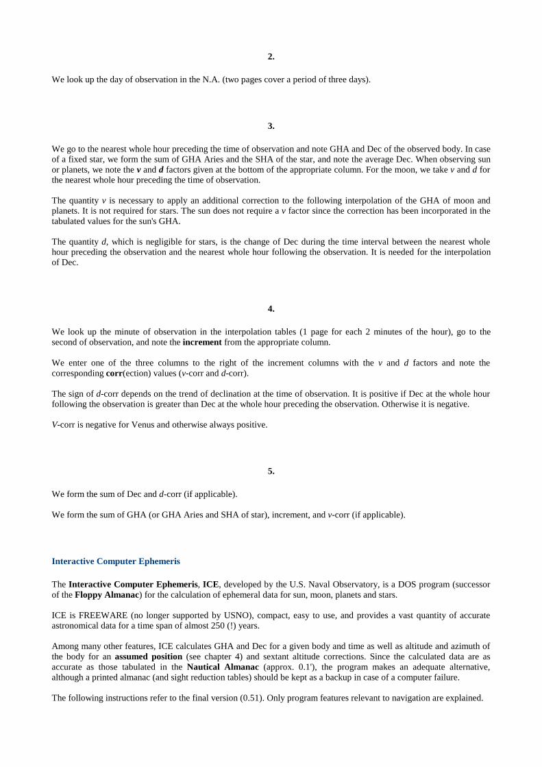
The time standard for celestial navigation is Greenwich Mean Time, GMT (now called Universal Time, UT). GMT isbased upon the GHA of the (fictitious) mean sun:
(If GMT is greater than 24 h, subtract 12 hours.)
In other words, GMT is the hour angle of the mean sun, expressed in hours, with respect to the lower branch of theGreenwich meridian (Fig. 3-5).
[ ] [ ]12
15+°= MeanSunGHA
hGMT

By definition, the GHA of the mean sun increases by exactly 15° per hour , completing a 360° cycle in 24 hours.Celestial coordinates tabulated in the Nautical Almanac refer to GMT (UT).
The hourly increase of the GHA of the apparent (observable) sun is subject to periodic changes and is sometimesslightly greater, sometimes slightly smaller than 15° during the course of a year. This behavior is caused by theeccentricity of the earth's orbit and by the obliquity of the ecliptic. The time derived from the GHA of the apparent sunis called Greenwich Apparent Time, GAT. A sundial located at the Greenwich meridian, for example, would indicateGAT. The difference between GAT and GMT is called equation of time, EoT:
EoT varies periodically between approx. -16 minutes and +16 minutes. Predicted values for EoT for each day of theyear (at 0:00 and 12:00 GMT) are given in the Nautical Almanac (grey background indicates negative EoT). EoT isneeded when calculating times of sunrise and sunset, or determining a noon longitude (see chapter 6). Formulas for thecalculation of EoT are given in chapter 15.
Due to the rapid change of GHA, celestial navigation requires accurate time measurement, and the time at theinstant of observation should be noted to the second if possible. This is usually done by means of a chronometer anda stopwatch. The effects of time errors are dicussed in chapter 16. If GMT (UT) is not available, UTC (CoordinatedUniversal Time) can be used. UTC, based upon highly accurate atomic clocks, is the standard for radio time signalsbroadcast by, e. g., WWV or WWVH* . Since GMT (UT) is linked to the earth's rotating speed which decreases slowlyand, moreover, with unpredictable irregularities, GMT (UT) and UTC tend to drift apart. For practical reasons, it isdesirable to keep the difference between GMT (UT) and UTC sufficiently small. To ensure that the difference, DUT,never exceeds ±0.9 s, UTC is synchronized with UT by inserting or omitting leap seconds at certain times, if necessary.Current values for DUT are published by the United StatesNaval Observatory, Ear th Or ientation Depar tment, on aregular basis (IERS Bulletin A).
*It is most confusing that nowadays the term GMT is often used as a synonym for UTC instead of UT. GMT time signals from radiostations generally refer to UTC. In this publication, the term GMT is always used in the traditional (astronomical) sense, as explainedabove.
Terrestr ial Dynamical Time, TDT, is an atomic time scale which is not synchronized with GMT (UT). It is acontinuous and linear time measure used in astronomy (calculation of ephemerides) and space flight. TDT is presently(2001) approx. 1 minute ahead of GMT.
The Nautical Almanac
Predicted values for GHA and Dec of sun, moon and the navigational planets with reference to GMT (UT) are tabulatedfor each whole hour of the year on the daily pages of the Nautical Almanac, N.A., and similar publications [12, 13].GHAAries is tabulated in the same manner.
Listing GHA and Dec of all 57 fixed stars used in navigation for each whole hour of the year would require too muchspace. Since declinations of stars and (apparent) positions of stars relative to each other change only slowly, tabulatedaverage siderial hour angles and declinations of stars for periods of 3 days are accurate enough for navigationalapplications.
GHA and Dec for each second of the year are obtained using the interpolation tables at the end of the N.A. (printed ontinted paper), as explained in the following directions:
1.
We note the exact time of observation (UTC or, preferably, UT), determined with a chronometer, for each celestialbody.
GMTGATEoT −=
DUTUTCUT +=
2.
We look up the day of observation in the N.A. (two pages cover a period of three days).
3.
We go to the nearest whole hour preceding the time of observation and note GHA and Dec of the observed body. In caseof a fixed star, we form the sum of GHA Aries and the SHA of the star, and note the average Dec. When observing sunor planets, we note the v and d factors given at the bottom of the appropriate column. For the moon, we take v and d forthe nearest whole hour preceding the time of observation.
The quantity v is necessary to apply an additional correction to the following interpolation of the GHA of moon andplanets. It is not required for stars. The sun does not require a v factor since the correction has been incorporated in thetabulated values for the sun's GHA.
The quantity d, which is negligible for stars, is the change of Dec during the time interval between the nearest wholehour preceding the observation and the nearest whole hour following the observation. It is needed for the interpolationof Dec.
4.
We look up the minute of observation in the interpolation tables (1 page for each 2 minutes of the hour), go to thesecond of observation, and note the increment from the appropriate column.
We enter one of the three columns to the right of the increment columns with the v and d factors and note thecorresponding corr(ection) values (v-corr and d-corr).
The sign of d-corr depends on the trend of declination at the time of observation. It is positive if Dec at the whole hourfollowing the observation is greater than Dec at the whole hour preceding the observation. Otherwise it is negative.
V-corr is negative for Venus and otherwise always positive.
5.
We form the sum of Dec and d-corr (if applicable).
We form the sum of GHA (or GHA Aries and SHA of star), increment, and v-corr (if applicable).
Interactive Computer Ephemeris
The Interactive Computer Ephemeris, ICE, developed by the U.S. Naval Observatory, is a DOS program (successorof the Floppy Almanac) for the calculation of ephemeral data for sun, moon, planets and stars.
ICE is FREEWARE (no longer supported by USNO), compact, easy to use, and provides a vast quantity of accurateastronomical data for a time span of almost 250 (!) years.
Among many other features, ICE calculates GHA and Dec for a given body and time as well as altitude and azimuth ofthe body for an assumed position (see chapter 4) and sextant altitude corrections. Since the calculated data are asaccurate as those tabulated in the Nautical Almanac (approx. 0.1'), the program makes an adequate alternative,although a printed almanac (and sight reduction tables) should be kept as a backup in case of a computer failure.
The following instructions refer to the final version (0.51). Only program features relevant to navigation are explained.
1. Installation Copy the program files to a chosen directory on the hard drive or to a floppy disk.
2. Getting Started Change to the program directory (or floppy disk) and enter "ice". The main menu appears. Use the function keys F1 toF10 to navigate through the submenus. The program is more or less self-explanatory.
Go to the submenu INITIAL VALUES (F1). Follow the directions on the screen to enter date and time of observation(F1), assumed latitude (F2), assumed longitude (F3), and your local time zone (F6). Assumed latitude and longitudedefine your assumed position. Use the correct data format, as shown on the screen (decimal format for latitude andlongitude). After entering the above data, press F7 to accept the values displayed.
To change the default values permanently, edit the file ice.dft with a text editor (after making a backup copy) and makethe appropriate changes. Do not change the data format. The numbers have to be in columns 21-40.
An output file can be created to store calculated data. Go to the submenu FILE OUTPUT (F2) and enter a chosen filename, e.g., OUTPUT.TXT.
3. Calculation of Navigational Data From the main menu, go to the submenu NAVIGATION (F7). Enter the name of the body. The program displays GHAand Dec of the body, GHA and Dec of the sun (if visible), and GHA of the vernal equinox for the time (UT) stored inINITIAL VALUES. Hc (computed altitude) and Zn (azimuth) mark the apparent position of the body as observed fromthe assumed position. Approximate altitude corrections (refraction, SD, PA), based upon Hc, are also displayed (forlower limb of body). The semidiameter of the moon includes augmentation. The coordinates calculated for Venus andMars do not include phase correction. Therefore, the upper or lower limb (if visible) should be observed. ∆T is TDT-UT, the difference between terrestrial dynamical time and UT for the date given (presently approx. 1 min.).
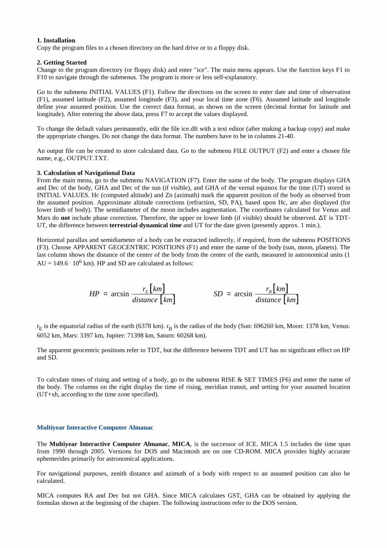
Horizontal parallax and semidiameter of a body can be extracted indirectly, if required, from the submenu POSITIONS(F3). Choose APPARENT GEOCENTRIC POSITIONS (F1) and enter the name of the body (sun, moon, planets). Thelast column shows the distance of the center of the body from the center of the earth, measured in astronomical units (1AU = 149.6 . 106 km). HP and SD are calculated as follows:
rE is the equatorial radius of the earth (6378 km). rB is the radius of the body (Sun: 696260 km, Moon: 1378 km, Venus:
6052 km, Mars: 3397 km, Jupiter: 71398 km, Saturn: 60268 km).
The apparent geocentric positions refer to TDT, but the difference between TDT and UT has no significant effect on HPand SD.
To calculate times of rising and setting of a body, go to the submenu RISE & SET TIMES (F6) and enter the name ofthe body. The columns on the right display the time of rising, meridian transit, and setting for your assumed location(UT+xh, according to the time zone specified).
Multiyear Interactive Computer Almanac
The Multiyear Interactive Computer Almanac, MICA, is the successor of ICE. MICA 1.5 includes the time spanfrom 1990 through 2005. Versions for DOS and Macintosh are on one CD-ROM. MICA provides highly accurateephemerides primarily for astronomical applications.
For navigational purposes, zenith distance and azimuth of a body with respect to an assumed position can also becalculated.
MICA computes RA and Dec but not GHA. Since MICA calculates GST, GHA can be obtained by applying theformulas shown at the beginning of the chapter. The following instructions refer to the DOS version.
[ ][ ]
[ ][ ]kmdistance
kmrSD
kmdistance
kmrHP BE arcsinarcsin ==
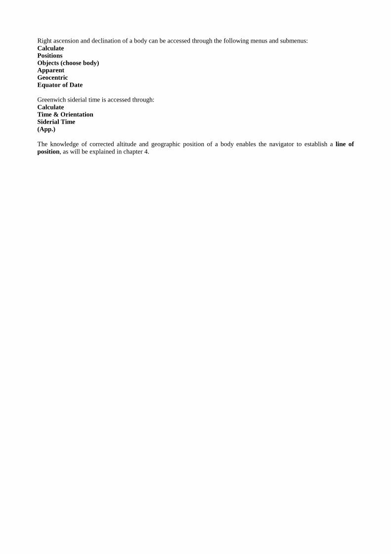
Right ascension and declination of a body can be accessed through the following menus and submenus: CalculatePositionsObjects (choose body)ApparentGeocentricEquator of Date
Greenwich siderial time is accessed through: CalculateTime & OrientationSiderial Time(App.)
The knowledge of corrected altitude and geographic position of a body enables the navigator to establish a line ofposition, as will be explained in chapter 4.
Chapter 4
Finding One's Position (Sight Reduction)
Lines of Position
Any geometrical or physical line passing through the observer's (still unknown) position and accessible throughmeasurement or observation is called a line of position, LoP. Examples are circles of equal altitude, meridians oflongitude, parallels of latitude, bearing lines (compass bearings) of terrestrial objects, coastlines, rivers, roads, orrailroad tracks. A single LoP indicates an infinite ser ies of possible positions. The observer 's actual position ismarked by the point of intersection of at least two LoP's, regardless of their nature. The concept of the positionline is essential to modern navigation.
Sight Reduction
Deriving a line of position from altitude and GP of a celestial object is called sight reduction in navigator´s language.Understanding the process completely requires some background in spherical trigonometry, but knowing the basicconcepts and a few equations is sufficient for most applications of celestial navigation. The theoretical explanation,using the law of cosines and the navigational tr iangle, is given in chapter 10 and 11. In the following, we will discussthe semi-graphic methods developed by Sumner and St. Hilaire. Both methods require relatively simple calculationsonly and enable the navigator to plot lines of position on a navigation chart or plotting sheet (see chapter 13).
Knowing altitude and GP of a body, we also know the radius of the corresponding circle of equal altitude (our line ofposition) and the location of its center. As mentioned in chapter 1 already, plotting circles of equal altitude directly on achart is usually impossible due to their large dimensions and the distortions caused by map projection. However,Sumner and St. Hilaire showed that only a small arc of each circle of equal altitude is needed to find one's position.Since this arc is comparatively short, it can be replaced with a secant or tangent a of the circle.
The Intercept Method
This is the most versatile and most popular sight reduction procedure. In the second half of the 19th century, the Frenchnavy officer and later admiral St. Hilaire found that a straight line tangent to the circle of equal altitude in the vicinityof the observer's position can be utilized as a line of position. The procedure comprises the following steps:
1.
First, we need an initial position which should be less than ca. 100 nm away from our actual (unknown) position. Thismay be our estimated position, our dead reckoning position, DRP (chapter 11), or an assumed position, AP. Wemark this position on our navigation chart or plotting sheet (chapter 13) and note the corresponding latitude andlongitude. An assumed position is a chosen point in the vicinity of our estimated position or DRP, preferably the nearestpoint on the chart where two grid lines intersect. An assumed position is sometimes preferred since it may be moreconvenient for plotting lines and measuring angles on the plotting sheet. Some sight reduction tables are based uponAP's because they require integer values for coordinates. The following procedures and formulas refer to an AP.They would be exactly the same, however , when using a DRP or an estimated position.
2.
Using the laws of spherical trigonometry (chapter 10 and 11), we calculate the altitude of the observed body as it wouldappear at our AP (reduced to the celestial horizon). This altitude is called calculated or computed altitude, Hc:
or
( )LHADecLatDecLatHc APAP coscoscossinsinarcsin ⋅⋅+⋅=
( )tDecLatDecLatHc APAP coscoscossinsinarcsin ⋅⋅+⋅=
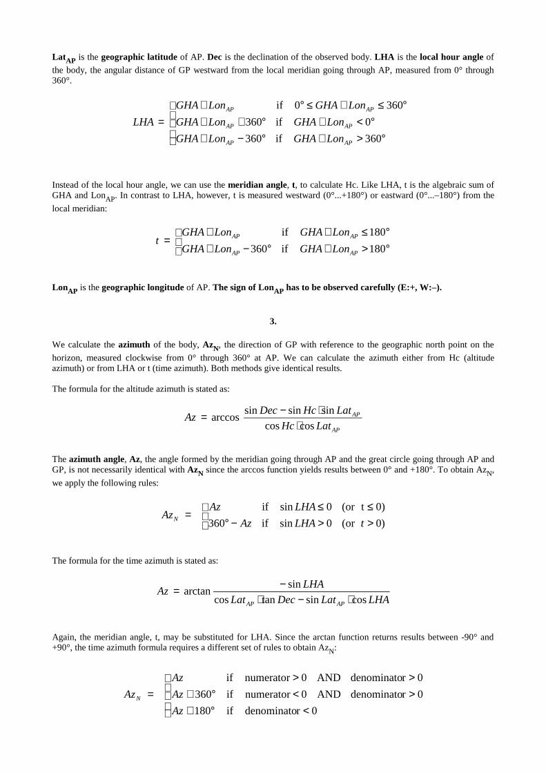
LatAP is the geographic latitude of AP. Dec is the declination of the observed body. LHA is the local hour angle of
the body, the angular distance of GP westward from the local meridian going through AP, measured from 0° through360°.
Instead of the local hour angle, we can use the mer idian angle, t, to calculate Hc. Like LHA, t is the algebraic sum ofGHA and LonAP. In contrast to LHA, however, t is measured westward (0°...+180°) or eastward (0°...–180°) from the
local meridian:
LonAP is the geographic longitude of AP. The sign of LonAP has to be observed carefully (E:+, W:–).
3.
We calculate the azimuth of the body, AzN, the direction of GP with reference to the geographic north point on the
horizon, measured clockwise from 0° through 360° at AP. We can calculate the azimuth either from Hc (altitudeazimuth) or from LHA or t (time azimuth). Both methods give identical results.
The formula for the altitude azimuth is stated as:
The azimuth angle, Az, the angle formed by the meridian going through AP and the great circle going through AP andGP, is not necessarily identical with AzN since the arccos function yields results between 0° and +180°. To obtain AzN,
we apply the following rules:
The formula for the time azimuth is stated as:
Again, the meridian angle, t, may be substituted for LHA. Since the arctan function returns results between -90° and+90°, the time azimuth formula requires a different set of rules to obtain AzN:
°>+°−+°<+°++
°≤+≤°+=
360if360
0if360
3600if
APAP
APAP
APAP
LonGHALonGHA
LonGHALonGHA
LonGHALonGHA
LHA
°>+°−+°≤++
=180if360
180if
APAP
APAP
LonGHALonGHA
LonGHALonGHAt
AP
AP
LatHc
LatHcDecAz
coscos
sinsinsinarccos
⋅⋅−=
>>−°≤≤
=)0or(0sinif360
0)t(or0sinif
tLHAAz
LHAAzAzN
LHALatDecLat
LHAAz
APAP cossintancos
sinarctan
⋅−⋅−=
<°+><°+>>
=0rdenominatoif180
0rdenominatoAND0numeratorif360
0rdenominatoAND0numeratorif
Az
Az
Az
AzN
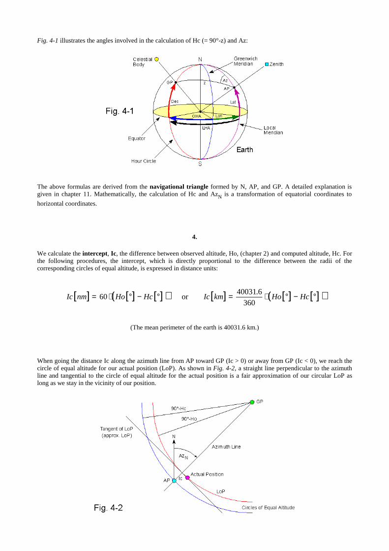
Fig. 4-1 illustrates the angles involved in the calculation of Hc (= 90°-z) and Az:
The above formulas are derived from the navigational triangle formed by N, AP, and GP. A detailed explanation isgiven in chapter 11. Mathematically, the calculation of Hc and AzN is a transformation of equatorial coordinates to
horizontal coordinates.
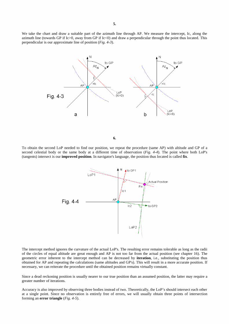
4.
We calculate the intercept, Ic, the difference between observed altitude, Ho, (chapter 2) and computed altitude, Hc. Forthe following procedures, the intercept, which is directly proportional to the difference between the radii of thecorresponding circles of equal altitude, is expressed in distance units:
(The mean perimeter of the earth is 40031.6 km.)
When going the distance Ic along the azimuth line from AP toward GP (Ic > 0) or away from GP (Ic < 0), we reach thecircle of equal altitude for our actual position (LoP). As shown in Fig. 4-2, a straight line perpendicular to the azimuthline and tangential to the circle of equal altitude for the actual position is a fair approximation of our circular LoP aslong as we stay in the vicinity of our position.
[ ] [ ] [ ]( ) [ ] [ ] [ ]( )°−°⋅=°−°⋅= HcHokmIcHcHonmIc360
6.40031or60
5.
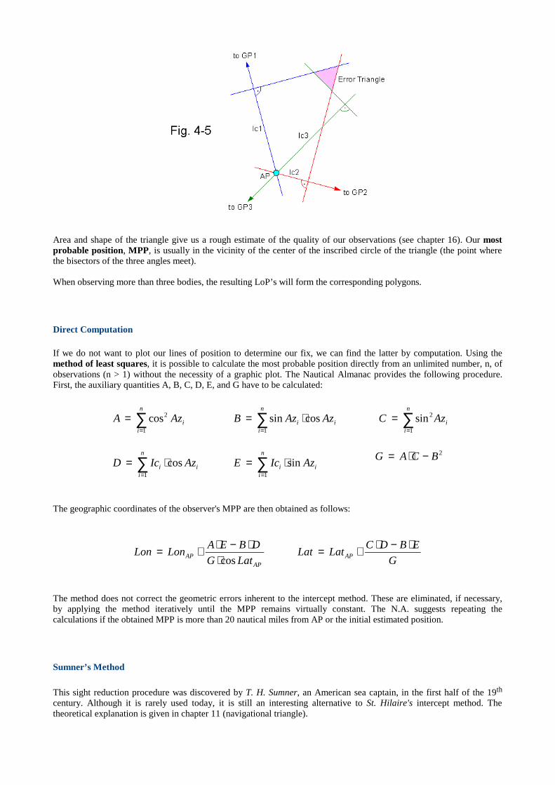
We take the chart and draw a suitable part of the azimuth line through AP. We measure the intercept, Ic, along theazimuth line (towards GP if Ic>0, away from GP if Ic<0) and draw a perpendicular through the point thus located. Thisperpendicular is our approximate line of position (Fig. 4-3).
6.
To obtain the second LoP needed to find our position, we repeat the procedure (same AP) with altitude and GP of asecond celestial body or the same body at a different time of observation (Fig. 4-4). The point where both LoP's(tangents) intersect is our improved position. In navigator's language, the position thus located is called fix.
The intercept method ignores the curvature of the actual LoP's. The resulting error remains tolerable as long as the radiiof the circles of equal altitude are great enough and AP is not too far from the actual position (see chapter 16). Thegeometric error inherent to the intercept method can be decreased by iteration, i.e., substituting the position thusobtained for AP and repeating the calculations (same altitudes and GP's). This will result in a more accurate position. Ifnecessary, we can reiterate the procedure until the obtained position remains virtually constant.
Since a dead reckoning position is usually nearer to our true position than an assumed position, the latter may require agreater number of iterations.
Accuracy is also improved by observing three bodies instead of two. Theoretically, the LoP’s should intersect each otherat a single point. Since no observation is entirely free of errors, we will usually obtain three points of intersectionforming an error triangle (Fig. 4-5).
Area and shape of the triangle give us a rough estimate of the quality of our observations (see chapter 16). Our mostprobable position, MPP, is usually in the vicinity of the center of the inscribed circle of the triangle (the point wherethe bisectors of the three angles meet).
When observing more than three bodies, the resulting LoP’s will form the corresponding polygons.
Direct Computation
If we do not want to plot our lines of position to determine our fix, we can find the latter by computation. Using themethod of least squares, it is possible to calculate the most probable position directly from an unlimited number, n, ofobservations (n > 1) without the necessity of a graphic plot. The Nautical Almanac provides the following procedure.First, the auxiliary quantities A, B, C, D, E, and G have to be calculated:
The geographic coordinates of the observer's MPP are then obtained as follows:
The method does not correct the geometric errors inherent to the intercept method. These are eliminated, if necessary,by applying the method iteratively until the MPP remains virtually constant. The N.A. suggests repeating thecalculations if the obtained MPP is more than 20 nautical miles from AP or the initial estimated position.
Sumner ’s Method
This sight reduction procedure was discovered by T. H. Sumner, an American sea captain, in the first half of the 19th
century. Although it is rarely used today, it is still an interesting alternative to St. Hilaire's intercept method. Thetheoretical explanation is given in chapter 11 (navigational triangle).
∑=
=n
iiAzA
1
2cos ∑=
⋅=n
iii AzAzB
1
cossin i
n
i
AzC ∑=
=1
2sin
∑=
⋅=n
iii AzIcD
1
cos i
n
ii AzIcE sin
1
⋅= ∑=
2BCAG −⋅=
G
EBDCLatLat
LatG
DBEALonLon AP
APAP
⋅−⋅+=⋅
⋅−⋅+=cos

Sumner had the brilliant idea to derive a line of position from the points where a circle of equal altitude intersects twochosen parallels of latitude, P1 and P2 (Fig. 4-6).
An observer being between the parallels P1 and P2 is either on the arc A-B or on the arc C-D. With an estimate of hislongitude, the observer can easily find on which of both arcs he is, for example, A-B. The arc thus found is the relevantpart of his line of position, the other arc is discarded. We can approximate the LoP by drawing a straight line through Aand B which is a secant of the circle of equal altitude. This secant is called Sumner line. Before plotting the Sumner lineon our chart, we have to find the longitudes of the points of intersection, A, B, C, and D. This is the procedure:
1.
We choose a parallel of latitude (P1) north of our estimated latitude. Preferably, the assumed latitude, Lat, should referto the nearest grid line on our chart or plotting sheet.
2.
Solving the altitude formula (see above) for t and substituting Ho for Hc, we get:
Now, t is a function of latitude, declination, and the observed altitude of the body. Lat is the assumed latitude. In otherwords, the meridian angle of a body is either +t or –t when an observer being at the latitude Lat measures the altitudeHo. Using the following formulas, we obtain the longitudes which mark the points where the circle of equal altitudeintersects the assumed parallel of latitude, for example, the points A and C if we choose P1:
Comparing the longitudes thus obtained with our estimated longitude, we select the relevant longitude and discard theother. This method of finding longitude is called time sight (see chapter 6).
GHAtLon −=1
°+→°−< 360180If 11 LonLon
GHAtLon −−°= 3602
°−→°+>
°+→°−<
360180If
360180If
22
22
LonLon
LonLon
DecLat
DecLatHot
coscos
sinsinsinarccos
⋅⋅−±=

3.
We chose a parallel of latitude (P2) south of our estimated latitude. The distance between P1 and P2 should not exceed1 or 2 degrees. We repeat steps 1 and 2 with the second parallel of latitude, P2.
4.
On our plotting sheet, we mark each remaining longitude on the corresponding parallel and plot the Sumner line throughthe points thus located.
To obtain a fix, we repeat the above procedure with the same parallels and a second body. The point where both Sumnerlines, LoP1 and LoP2, intersect is our fix (Fig. 4-7).
If both assumed parallels of latitude are either north or south of our actual position, we will of course find the point ofintersection outside the interval defined by both parallels. Nevertheless, a fix thus obtained is correct.
A fix obtained with Sumner's method, too, has a small error caused by neglecting the curvature of the circles of equalaltitude. Similar to the intercept method, we can improve the fix by iteration. In this case, we choose a new pair ofassumed latitudes, nearer to the fix, and repeat the whole procedure.
A Sumner line may be inaccurate under certain conditions (see time sight, chapter 6). Apart from these restrictions,Sumner's method is fully adequate. It has even the advantage that lines of position are plotted without a protractor.
As with the intercept method, we can plot Sumner lines resulting from three (or more) observations to obtain an errortriangle (polygon).
Sumner's method revolutionized celestial navigation and can be considered as the beginning of modern position linenavigation which was later perfected by St. Hilaire's intercept method.
Combining Different Lines of Position
Since the point of intersection of any two LoP's, regardless of their nature, marks the observer'sgeographic position, onecelestial LoP may suffice to find one's position if another LoP of a different kind is available.
In the desert, for instance, we can determine our current position by finding the point on the map where a LoP obtainedby observation of a celestial object intersects the dirt road we are traveling on (Fig. 4-8).
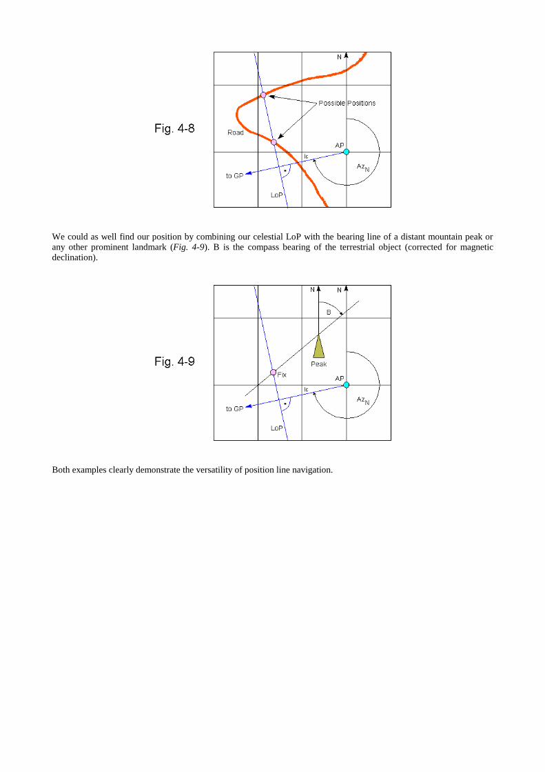
We could as well find our position by combining our celestial LoP with the bearing line of a distant mountain peak orany other prominent landmark (Fig. 4-9). B is the compass bearing of the terrestrial object (corrected for magneticdeclination).
Both examples clearly demonstrate the versatility of position line navigation.

Chapter 5
Finding the Position of a Traveling Vessel
The intercept method even enables the navigator to determine the position of a vessel traveling a considerable distancebetween two observations, provided course and speed over ground are known.
We begin with plotting both lines of position in the usual manner, as illustrated in chapter 4, Fig. 4-4. Then, we applythe vector of motion (defined by course, speed, and time elapsed) to the LoP resulting from the first observation, andplot the advanced first LoP, the parallel of the first LoP thus obtained. The point where the advanced first LoPintersects the second LoP is the position of the vessel at the time of the second observation. A position obtained inthis fashion is called a running fix (Fig. 5-1).
The procedure gives good results when traveling short distances (up to approx. 30 nm) between the observations. Whentraveling a larger distance (up to approx. 150 nm), it may be necessary to choose two different AP's, not too far awayfrom each estimated position, to reduce geometric errors (Fig. 5-2).
It is also possible to find the running fix for the time of the first observation. In this case the second LoP has to beretarded (moved backwards).
Sumner lines and terrestrial lines of position may be advanced or retarded in the same manner.
In practice, course and speed over ground can only be estimated since the exact effects of currents and wind are usuallynot known. Therefore, a running fix is usually not as accurate as a stationary fix.
Chapter 6
Methods for Latitude and Longitude Measurement
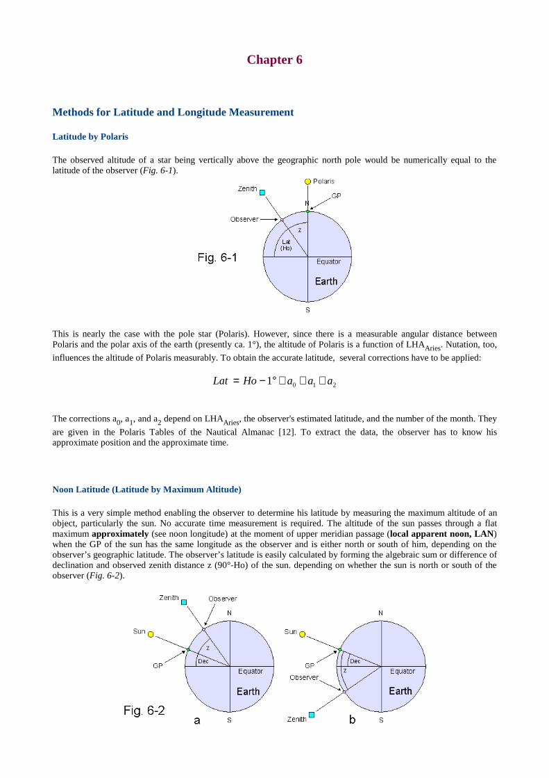
Latitude by Polaris
The observed altitude of a star being vertically above the geographic north pole would be numerically equal to thelatitude of the observer (Fig. 6-1).
This is nearly the case with the pole star (Polaris). However, since there is a measurable angular distance betweenPolaris and the polar axis of the earth (presently ca. 1°), the altitude of Polaris is a function of LHAAries. Nutation, too,
influences the altitude of Polaris measurably. To obtain the accurate latitude, several corrections have to be applied:
The corrections a0, a1, and a2 depend on LHAAries, the observer'sestimated latitude, and the number of the month. They
are given in the Polaris Tables of the Nautical Almanac [12]. To extract the data, the observer has to know hisapproximate position and the approximate time.
Noon Latitude (Latitude by Maximum Altitude)
This is a very simple method enabling the observer to determine his latitude by measuring the maximum altitude of anobject, particularly the sun. No accurate time measurement is required. The altitude of the sun passes through a flatmaximum approximately (see noon longitude) at the moment of upper meridian passage (local apparent noon, LAN)when the GP of the sun has the same longitude as the observer and is either north or south of him, depending on theobserver’s geographic latitude. The observer’s latitude is easily calculated by forming the algebraic sum or difference ofdeclination and observed zenith distance z (90°-Ho) of the sun. depending on whether the sun is north or south of theobserver (Fig. 6-2).
2101 aaaHoLat +++°−=
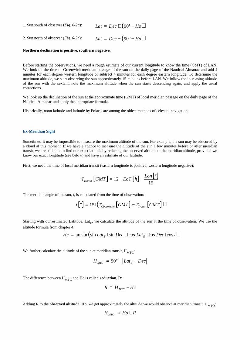
1. Sun south of observer (Fig. 6-2a): ( )HoDecLat −°+= 90
2. Sun north of observer (Fig. 6-2b): ( )HoDecLat −°−= 90
Northern declination is positive, southern negative.
Before starting the observations, we need a rough estimate of our current longitude to know the time (GMT) of LAN.We look up the time of Greenwich meridian passage of the sun on the daily page of the Nautical Almanac and add 4minutes for each degree western longitude or subtract 4 minutes for each degree eastern longitude. To determine themaximum altitude, we start observing the sun approximately 15 minutes before LAN. We follow the increasing altitudeof the sun with the sextant, note the maximum altitude when the sun starts descending again, and apply the usualcorrections.
We look up the declination of the sun at the approximate time (GMT) of local meridian passage on the daily page of theNautical Almanac and apply the appropriate formula.
Historically, noon latitude and latitude by Polaris are among the oldest methods of celestial navigation.
Ex-Meridian Sight
Sometimes, it may be impossible to measure the maximum altitude of the sun. For example, the sun may be obscured bya cloud at this moment. If we have a chance to measure the altitude of the sun a few minutes before or after meridiantransit, we are still able to find our exact latitude by reducing the observed altitude to the meridian altitude, provided weknow our exact longitude (see below) and have an estimate of our latitude.
First, we need the time of local meridian transit (eastern longitude is positive, western longitude negative):
The meridian angle of the sun, t, is calculated from the time of observation:
Starting with our estimated Latitude, LatE, we calculate the altitude of the sun at the time of observation. We use the
altitude formula from chapter 4:
We further calculate the altitude of the sun at meridian transit, HMTC:
The difference between HMTC and Hc is called reduction, R:
Adding R to the observed altitude, Ho, we get approximately the altitude we would observe at meridian transit, HMTO:
[ ] [ ] [ ]15
12°−−= Lon
hEoTGMTTTransit
[ ] [ ] [ ]( )GMTTGMTTt TransitnObservatio −⋅=° 15
( )tDecLatDecLatHc EE coscoscossinsinarcsin ⋅⋅+⋅=
DecLatH EMTC −−°= 90
HcHR MTC −=
RHoH MTO +≈
From HMTO, we can calculate our improved latitude, Latimproved:
(sun south of observer: +, sun north of observer: –)
The exact latitude is obtained by iteration, i. e., we substitute Latimproved for LatE and repeat the calculations until the
obtained latitude is virtually constant. Usually, no more than one or two iterations are necessary. The method has a fewlimitations and requires critical judgement. The meridian angle should be smaller than about one quarter of the expectedzenith distance at meridian transit (zMT = LatE–Dec), and the meridian zenith distance should be at least four times
greater than the estimated error of LatE. Otherwise, a greater number of iterations may be necessary. Dec must not lie
between LatE and the true latitude because the method yields erratic results in such cases. If in doubt, we can calculate
with different estimated latitudes and compare the results. For safety reasons, the sight should be discarded if themeridian altitude exceeds approx. 85°. If t isnot a small angle (t > 1°), we may have to correct the latitude last found forthe change in declination between the time of observation and the time of meridian transit, depending on the current rateof change of Dec.
Noon Longitude (Longitude by Equal Altitudes, Longitude by Meridian Transit)
Since the earth rotates with an angular velocity of 15° per hour with respect to the mean sun, the time of local meridiantransit (local apparent noon) of the sun, TTransit, can be used to calculate the observer's longitude:
TTransit is measured as GMT (decimal format). The correction for EoT at the time of meridian transit, EoTTransit, has to
be made because the apparent sun, not the mean sun, is observed (see chapter 3). Since the Nautical Almanac containsonly values for EoT (see chapter 3) at 0:00 GMT and 12:00 GMT of each day, EoTTransit has to be found by
interpolation.
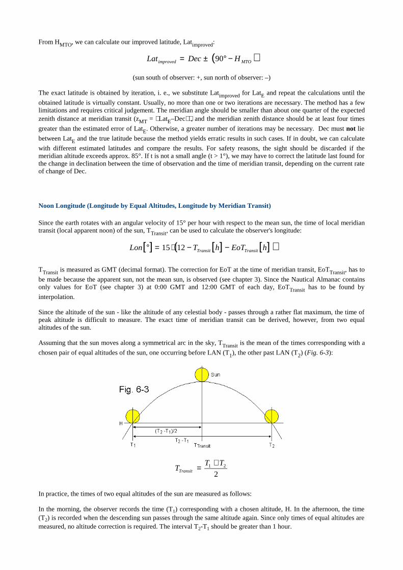
Since the altitude of the sun - like the altitude of any celestial body - passes through a rather flat maximum, the time ofpeak altitude is difficult to measure. The exact time of meridian transit can be derived, however, from two equalaltitudes of the sun.
Assuming that the sun moves along a symmetrical arc in the sky, TTransit is the mean of the times corresponding with a
chosen pair of equal altitudes of the sun, one occurring before LAN (T1), the other past LAN (T2) (Fig. 6-3):
In practice, the times of two equal altitudes of the sun are measured as follows:
In the morning, the observer records the time (T1) corresponding with a chosen altitude, H. In the afternoon, the time(T2) is recorded when the descending sun passes through the same altitude again. Since only times of equal altitudes aremeasured, no altitude correction is required. The interval T2-T1 should be greater than 1 hour.
( )MTOimproved HDecLat −°±= 90
[ ] [ ] [ ]( )hEoThTLon TransitTransit −−⋅=° 1215
221 TT
TTransit
+=
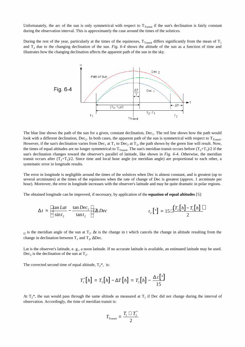
Unfortunately, the arc of the sun is only symmetrical with respect to TTransit if the sun's declination is fairly constantduring the observation interval. This is approximately the case around the times of the solstices.
During the rest of the year, particularly at the times of the equinoxes, TTransit differs significantly from the mean of T1
and T2 due to the changing declination of the sun. Fig. 6-4 shows the altitude of the sun as a function of time andillustrates how the changing declination affects the apparent path of the sun in the sky.
The blue line shows the path of the sun for a given, constant declination, Dec1. The red line shows how the path wouldlook with a different declination, Dec2. In both cases, the apparent path of the sun is symmetrical with respect to TTransit.However, if the sun'sdeclination varies from Dec1 at T1 to Dec2 at T2, the path shown by the green line will result. Now,the times of equal altitudes are no longer symmetrical to TTransit. The sun's meridian transit occurs before (T2+T1)/2 if thesun's declination changes toward the observer's parallel of latitude, like shown in Fig. 6-4. Otherwise, the meridiantransit occurs after (T2+T1)/2. Since time and local hour angle (or meridian angle) are proportional to each other, asystematic error in longitude results.
The error in longitude is negligible around the times of the solstices when Dec is almost constant, and is greatest (up toseveral arcminutes) at the times of the equinoxes when the rate of change of Dec is greatest (approx. 1 arcminute perhour). Moreover, the error in longitude increases with the observer's latitude and may be quite dramatic in polar regions.
The obtained longitude can be improved, if necessary, by application of the equation of equal altitudes [5]:
t2 is the meridian angle of the sun at T2. ∆t is the change in t which cancels the change in altitude resulting from the
change in declination between T1 and T2, ∆Dec.
Lat is the observer's latitude, e. g., a noon latitude. If no accurate latitude is available, an estimated latitude may be used.Dec2 is the declination of the sun at T2.
The corrected second time of equal altitude, T2*, is:
At T2*, the sun would pass through the same altitude as measured at T1 if Dec did not change during the interval ofobservation. Accordingly, the time of meridian transit is:
Dect
Dec
t
Latt ∆⋅
−≈∆
2
2
2 tan
tan
sin
tan [ ] [ ] [ ]( )2
15 122
hThTt
−⋅≈°
[ ] [ ] [ ] [ ] [ ]1522
*2
°∆−=∆−= thThThThT
2
*21 TT
TTransit
+=
The correction is very accurate if the exact value for ∆Dec is known. Calculating ∆Dec with MICA yields a morereliable correction than extracting ∆Dec from the Nautical Almanac. If no precise computer almanac is available, ∆Decshould be calculated from the daily change of declination to keep the rounding error as small as possible.
Although the equation of equal altitudes isstrictly valid only for an infinitesimal change of Dec, dDec, it can be used fora measurable change, ∆Dec, (up to several arcminutes) as well without sacrificing much accuracy. Accurate timemeasurement provided, the residual error in longitude should be smaller than ±0.1' in most cases.
The above formulas are not only suitable to determine one's exact longitude but can also be used to determine thechronometer error if one's exact position is known. This is done by comparing the time of meridian transit calculatedfrom one's longitude with the time of meridian transit derived from the observation of two equal altitudes.
Fig. 6-5 shows that the maximum altitude of the sun is slightly different from the altitude at the moment of meridianpassage if the declination changes. Since the sun'shourly change of declination isnever greater than approx. 1' and sincethe maximum of altitude is rather flat, the resulting error of a noon latitude is not significant (see end of chapter).
The equation of equal altitudes is derived from the altitude formula (see chapter 4) using differential calculus:
First, we want to know how a small change in declination would affect sin H. We differentiate sin H with respect to Dec:
Thus, the change in sin H caused by an infinitesimal change in declination, d Dec, is:
Now we differentiate sin H with respect to t in order to find out how a small change in the meridian angle would affectsin H:
The change in sin H caused by an infinitesimal change in the meridian angle, dt, is:
Since we want both effects to cancel each other, the total differential has to be zero:
tDecLatDecLatH coscoscossinsinsin ⋅⋅+⋅=
( )tDecLatDecLat
Dec
Hcossincoscossin
sin ⋅⋅−⋅=∂
∂
( ) ( ) DecdtDecLatDecLatDecdDec
H ⋅⋅⋅−⋅=⋅∂
∂cossincoscossin
sin
( )tDecLat
t
Hsincoscos
sin ⋅⋅−=∂
∂
( )tdtDecLattd
t
H ⋅⋅⋅−=⋅∂
∂sincoscos
sin
( ) ( )0
sinsin =⋅∂
∂+⋅∂
∂td
t
HDecd
Dec
H
( ) ( )Decd
Dec
Htd
t
H ⋅∂
∂=⋅∂
∂− sinsin
Longitude Measurement on a Traveling Vessel
On a traveling vessel, we have to take into account not only the influence of varying declination but also the effects ofchanging latitude and longitude on sin H during the observation interval. Again, the total differential has to be zerobecause we want the combined effects to cancel each other with respect to their influence on sin H:
Differentiating sin H (altitude formula) with respect to Lat, we get:
Thus, the total change in t caused by the combined variations in Dec, Lat, and Lon is:
dLat and dLon are the infinitesimal changes in latitude and longitude caused by the vessel's movement during theobservation interval. For practical purposes, we can substitute the measurable changes ∆Dec, ∆Lat and ∆Lon for dDec,dLat and dLon (resulting in the measurable change ∆t). ∆Lat and ∆Lon are calculated from course, C, and velocity, v,over ground and the time elapsed:
Again, the corrected second time of equal altitude is:
The longitude thus calculated refers to T1. The longitude at T2 is Lon+∆Lon.
( ) DecdtDecLatDecLattdtDecLat ⋅⋅⋅−⋅=⋅⋅⋅ cossincoscossinsincoscos
Decdt
Dec
t
Lattd ⋅
−=
tan
tan
sin
tan
( ) ( ) ( ) ( )0
sinsinsin =⋅∂
∂+⋅∂
∂++⋅∂
∂Decd
Dec
HLatd
Lat
HLondtd
t
H
( ) ( ) ( ) ( )Decd
Dec
HLatd
Lat
HLondtd
t
H ⋅∂
∂+⋅∂
∂=+⋅∂
∂− sinsinsin
( )tDecLatDecLat
Lat
Hcoscossinsincos
sin ⋅⋅−⋅=∂
∂
LondLatdt
Lat
t
DecDecd
t
Dec
t
Lattd −⋅
−+⋅
−=
tan
tan
sin
tan
tan
tan
sin
tan
[ ] [ ] [ ] [ ]( )hThTCknvLat 12cos' −⋅⋅=∆
DecdtDecLat
tDecLatDecLattd ⋅
⋅⋅⋅⋅−⋅=
sincoscos
cossincoscossin
[ ] [ ] [ ] [ ]( )hThTLat
CknvLon 12cos
sin' −⋅⋅=∆
( ) hnmknotkn /11 =
[ ] [ ] [ ]152
*2
°∆−== thThT
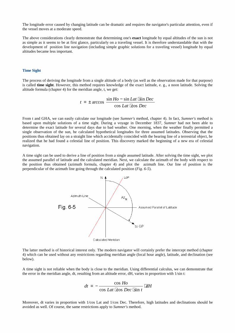
The longitude error caused by changing latitude can be dramatic and requires the navigator's particular attention, even ifthe vessel moves at a moderate speed.
The above considerations clearly demonstrate that determining one's exact longitude by equal altitudes of the sun is notas simple as it seems to be at first glance, particularly on a traveling vessel. It is therefore understandable that with thedevelopment of position line navigation (including simple graphic solutions for a traveling vessel) longitude by equalaltitudes became less important.
Time Sight
The process of deriving the longitude from a single altitude of a body (as well as the observation made for that purpose)is called time sight. However, this method requires knowledge of the exact latitude, e. g., a noon latitude. Solving thealtitude formula (chapter 4) for the meridian angle, t, we get:
From t and GHA, we can easily calculate our longitude (see Sumner's method, chapter 4). In fact, Sumner's method isbased upon multiple solutions of a time sight. During a voyage in December 1837, Sumner had not been able todetermine the exact latitude for several days due to bad weather. One morning, when the weather finally permitted asingle observation of the sun, he calculated hypothetical longitudes for three assumed latitudes. Observing that thepositions thus obtained lay on a straight line which accidentally coincided with the bearing line of a terrestrial object, herealized that he had found a celestial line of position. This discovery marked the beginning of a new era of celestialnavigation.
A time sight can be used to derive a line of position from a single assumed latitude. After solving the time sight, we plotthe assumed parallel of latitude and the calculated meridian. Next, we calculate the azimuth of the body with respect tothe position thus obtained (azimuth formula, chapter 4) and plot the azimuth line. Our line of position is theperpendicular of the azimuth line going through the calculated position (Fig. 6-5).
The latter method is of historical interest only. The modern navigator will certainly prefer the intercept method (chapter4) which can be used without any restrictions regarding meridian angle (local hour angle), latitude, and declination (seebelow).
A time sight is not reliable when the body is close to the meridian. Using differential calculus, we can demonstrate thatthe error in the meridian angle, dt, resulting from an altitude error, dH, varies in proportion with 1/sin t:
Moreover, dt varies in proportion with 1/cos Lat and 1/cos Dec. Therefore, high latitudes and declinations should beavoided as well. Of course, the same restrictions apply to Sumner's method.
DecLat
DecLatHot
coscos
sinsinsinarccos
⋅⋅−±=
dHtDecLat
Hodt ⋅
⋅⋅−=
sincoscos
cos

The Meridian Angle of the Sun at Maximum Altitude
As mentioned above, the moment of maximum altitude does not exactly coincide with the upper meridian transit of thesun (or any other body) if the declination is changing. At maximum altitude, the rate of change of altitude caused by thechanging declination cancels the rate of change of altitude caused by the changing meridian angle. The equation of equalaltitude can be used to calculate the meridian angle of the sun at this moment. We divide each side of the equation by theinfinitesimal time interval dT:
Measuring the rate of change of t and Dec in arcminutes per hour we get:
Sine t is very small, we can substitute tan t for sin t:
Now, we can solve the equation for tan t:
Since a small angle (in radians) is nearly equal to its tangent, we get:
Measuring t in arcminutes, the equation is stated as:
dDec/dT is the rate of change of declination measured in arcminutes per hour.
The maximum altitude occurs after LAN if t is positive, and before LAN if t is negative.
For example, at the time of the spring equinox (Dec = 0, dDec/dT ≈ +1'/h) an observer being at +80° (N) latitude wouldobserve the maximum altitude of the sun at t ≈ +21.7', i. e., 86.7 seconds after meridian transit (LAN). An observer at+45° latitude, however, would observe the maximum altitude at t ≈ +3.82', i. e., only 15.3 seconds after meridian transit.
We can use the last equation to evaluate the systematic error of a noon latitude. The latter is known to be based upon themaximum altitude, not on the meridian altitude of the sun. Following the above example, the observer at 80° latitudewould observe the maximum altitude 86.7 seconds after meridian transit. During this interval, the declination of the sunwould have changed from 0 to +1.445'' (assuming that Dec is 0 at the time of meridian transit). Using the altitudeformula (chapter 4), we get:
Td
Decd
t
Dec
t
Lat
Td
td ⋅
−=
tan
tan
sin
tan
[ ][ ]hTd
Decd
t
Dec
t
Lath
'
tan
tan
sin
tan/'900 ⋅
−=
[ ][ ]hTd
Decd
t
DecLat '
tan
tantan900 ⋅−≈
[ ][ ]hTd
DecdDecLatt
'
900
tantantan ⋅−≈
[ ] ( ) [ ][ ]hTd
DecdDecLatt
'tantan82.3' ⋅−⋅≈
( ) ''72.0'010'7.21cos''445.1cos80cos''445.1sin80sinarcsin °=⋅⋅°+⋅°=Hc
[ ] [ ][ ]hTd
DecdDecLatt
'
900
tantan
180⋅−≈⋅° π
In contrast, the calculated altitude at meridian transit would be exactly 10°. Thus, the error of the noon latitude would be-0.72''.
In the same way, we can calculate the maximum altitude of the sun observed at 45° latitude:
In this case, the error of the noon latitude would be only -0.13''.
The above examples show that even at the times of the equinoxes, the systematic error of a noon latitude caused by thechanging declination of the sun is much smaller than other observational errors, e. g., the errors in dip or refraction. Asignificant error in latitude can only occur if the observer is very close to one of the poles (tan Lat!). Around the times ofthe solstices, the error in latitude is practically non-existent.
( ) ''13.0'045'82.3cos''255.0cos45cos''255.0sin45sinarcsin °=⋅⋅°+⋅°=Hc
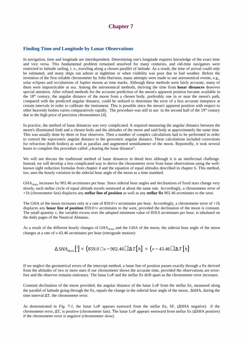
Chapter 7
Finding Time and Longitude by Lunar Observations
In navigation, time and longitude are interdependent. Determining one's longitude requires knowledge of the exact timeand vice versa. This fundamental problem remained unsolved for many centuries, and old-time navigators wererestricted to latitude sailing, i. e., traveling along a chosen parallel of latitude. As a result, the time of arrival could onlybe estimated, and many ships ran ashore at nighttime or when visibility was poor due to bad weather. Before theinvention of the first reliable chronometer by John Harrison, many attempts were made to use astronomical events, e.g.,solar eclipses and occultations of Jupiter moons as time marks. Although these methods were fairly accurate, many ofthem were impracticable at sea. Among the astronomical methods, deriving the time from lunar distances deservesspecial attention. After refined methods for the accurate prediction of the moon's apparent position became available inthe 18th century, the angular distance of the moon from a chosen body, preferably one in or near the moon's path,compared with the predicted angular distance, could be utilized to determine the error of a less accurate timepiece atcertain intervals in order to calibrate the instrument. This is possible since the moon's apparent position with respect toother heavenly bodies variescomparatively rapidly. The procedure was still in use in the second half of the 19th centurydue to the high price of precision chronometers [4].
In practice, the method of lunar distances was very complicated. It required measuring the angular distance between themoon's illuminated limb and a chosen body and the altitudes of the moon and said body at approximately the same time.This was usually done by three or four observers. Then a number of complex calculations had to be performed in orderto convert the topocentric angular distance to the geocentric angular distance. These calculations included correctionsfor refraction (both bodies) as well as parallax and augmented semidiameter of the moon. Reportedly, it took severalhours to complete this procedure called „clearing the lunar distance“.
We will not discuss the traditional method of lunar distances in detail here although it is an intellectual challenge.Instead, we will develop a less complicated way to derive the chronometer error from lunar observations using the well-known sight reduction formulas from chapter 4 and the equation of equal altitudes described in chapter 6. This method,too, uses the hourly variation in the siderial hour angle of the moon as a time standard.
GHAAries increases by 902.46 arcminutes per hour. Since siderial hour anglesand declinationsof fixed starschange veryslowly, each stellar circle of equal altitude travels westward at about the same rate. Accordingly, a chronometer error of+1h (chronometer fast) displaces any stellar line of position as well as any stellar fix 902.46 arcminutes to the west.
The GHA of the moon increases only at a rate of 859.0+v arcminutes per hour. Accordingly, a chronometer error of +1hdisplaces any lunar line of position 859.0+v arcminutes to the west, provided the declination of the moon is constant.The small quantity v, the variable excess over the adopted minimum value of 859.0 arcminutes per hour, is tabulated onthe daily pages of the Nautical Almanac.
As a result of the different hourly changes of GHAAries and the GHA of the moon, the siderial hour angle of the moonchanges at a rate of v-43.46 arcminutes per hour (retrograde motion):
If we neglect the geometrical errors of the intercept method, a lunar line of position passes exactly through a fix derivedfrom the altitudes of two or more stars if our chronometer shows the accurate time, provided the observations are error-free and the observer remains stationary. The lunar LoP and the stellar fix drift apart as the chronometer error increases.
Constant declination of the moon provided, the angular distance of the lunar LoP from the stellar fix, measured alongthe parallel of latitude going through the fix, equals the change in the siderial hour angle of the moon, ∆SHA, during thetime interval ∆T, the chronometer error.
As demonstrated in Fig. 7-1, the lunar LoP appears eastward from the stellar fix, SF, (∆SHA negative) if thechronometer error, ∆T, is positive (chronometer fast). Τhe lunar LoP appears westward from stellar fix (∆SHA positive)if the chronometer error is negative (chronometer slow).
[ ] ( ) [ ] ( ) [ ]hTvhTvSHAMoon ∆⋅−=∆⋅−+=∆ 46.4346.9020.859'
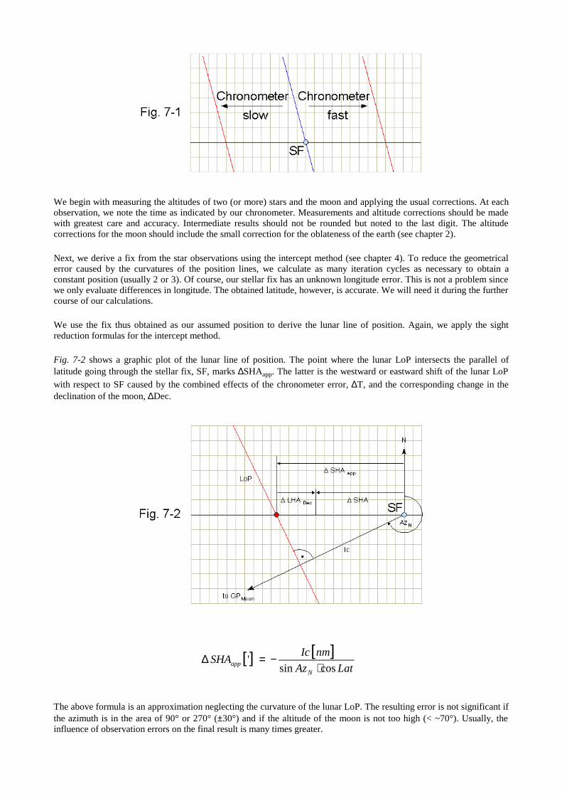
We begin with measuring the altitudes of two (or more) stars and the moon and applying the usual corrections. At eachobservation, we note the time as indicated by our chronometer. Measurements and altitude corrections should be madewith greatest care and accuracy. Intermediate results should not be rounded but noted to the last digit. The altitudecorrections for the moon should include the small correction for the oblateness of the earth (see chapter 2).
Next, we derive a fix from the star observations using the intercept method (see chapter 4). To reduce the geometricalerror caused by the curvatures of the position lines, we calculate as many iteration cycles as necessary to obtain aconstant position (usually 2 or 3). Of course, our stellar fix has an unknown longitude error. This is not a problem sincewe only evaluate differences in longitude. The obtained latitude, however, is accurate. We will need it during the furthercourse of our calculations.
We use the fix thus obtained as our assumed position to derive the lunar line of position. Again, we apply the sightreduction formulas for the intercept method.
Fig. 7-2 shows a graphic plot of the lunar line of position. The point where the lunar LoP intersects the parallel oflatitude going through the stellar fix, SF, marks ∆SHAapp. The latter is the westward or eastward shift of the lunar LoPwith respect to SF caused by the combined effects of the chronometer error, ∆T, and the corresponding change in thedeclination of the moon, ∆Dec.
The above formula isan approximation neglecting the curvature of the lunar LoP. The resulting error is not significant ifthe azimuth is in the area of 90° or 270° (±30°) and if the altitude of the moon is not too high (< ~70°). Usually, theinfluence of observation errors on the final result is many times greater.
[ ] [ ]LatAz
nmIcSHA
Napp cossin
'⋅
−=∆
∆SHA equals ∆SHAapp only if the moon's declination is constant during the interval ∆Τ. Usually, the moon's declinationchanges rapidly. The quantity d tabulated on the daily pages of the Nautical Almanac is the hourly change in declinationmeasured in arcminutes. We remember that d can be positive or negative, depending on the current trend of declination.The change in Dec during the interval ∆T is:
∆Dec is equivalent to a change in the local hour angle, ∆LHADec, if we consider equal altitudes of the moon. ∆LHADec
can be positive or negative. We can calculate ∆LHADec with the equation of equal altitudes (see chapter 6):
LHA is the algebraic sum of the GHA of the moon and the longitude of the stellar fix.
Thus, we get:
∆SHA is the algebraic sum of ∆SHAapp and ∆LHADec:
Combining the above formulas, we have:
Solving the equation for ∆T (in seconds of time), we get the chronometer error:
According to the hourly variation of GHAAries, our improved longitude is:
Lon is the raw longitude obtained by our observations of stars.
One should have no illusions about the accuracy of longitudes obtained by lunar distances and related methods sincesmall observation errors result in large errors in time and longitude. This is due to the fact that siderial hour angle anddeclination of the moon change slowly compared with the rate of change of GHA which is the basis for usual sightreduction procedures. Longitude errors of 1° were considered as normal in the days of lunar distances when nothingbetter was available.
[ ] [ ]hTdDec ∆⋅=∆ '
Decapp LHASHASHA ∆+∆=∆
( ) [ ] [ ] [ ]LatAz
nmIchTdfhTv
N cossin46.43
⋅−∆⋅⋅=∆⋅−
[ ] [ ]( ) LatAzdfv
nmIcsT
N cossin46.433600
⋅⋅⋅+−⋅=∆
[ ] [ ]sTCCLonLonimproved ∆⋅=+= 25068.0'
−=∆⋅=∆
LHA
Dec
LHA
LatfDecfLHADec tan
tan
sin
tan
[ ] [ ]hTdfLHADec ∆⋅⋅=∆ '
The above method works best if the azimuth of the moon is 90° or 270°. In practice, an azimuth of 90°±30° or 270°±30°is acceptable. The optimum altitude of the moon is a trade-off between refraction errors (low altitude) and the curvatureof the LoP (high altitudes). Therefore, medium altitudes (20°-60°) are preferred. The accuracy of the method decreaseswith increasing latitude. Therefore, it should not be used in polar regions. In any case, the observer has to be stationary.If the Observer's position changes during the observations, intolerable errors will result. The overall error can bereduced by multiple observations. It is therefore recommended to make a series of observations (see chapter 16).
Compared with the traditional method of lunar distances, the above procedure has not only the advantage that therequired formulas are much simpler but also that it can be managed by one person since it is not necessary to make theobservations at the same time. On land, relatively accurate results can be obtained when using a theodolite to measurethe altitudes. In this case, the residual error in longitude usually does not exceed a few arcminutes.
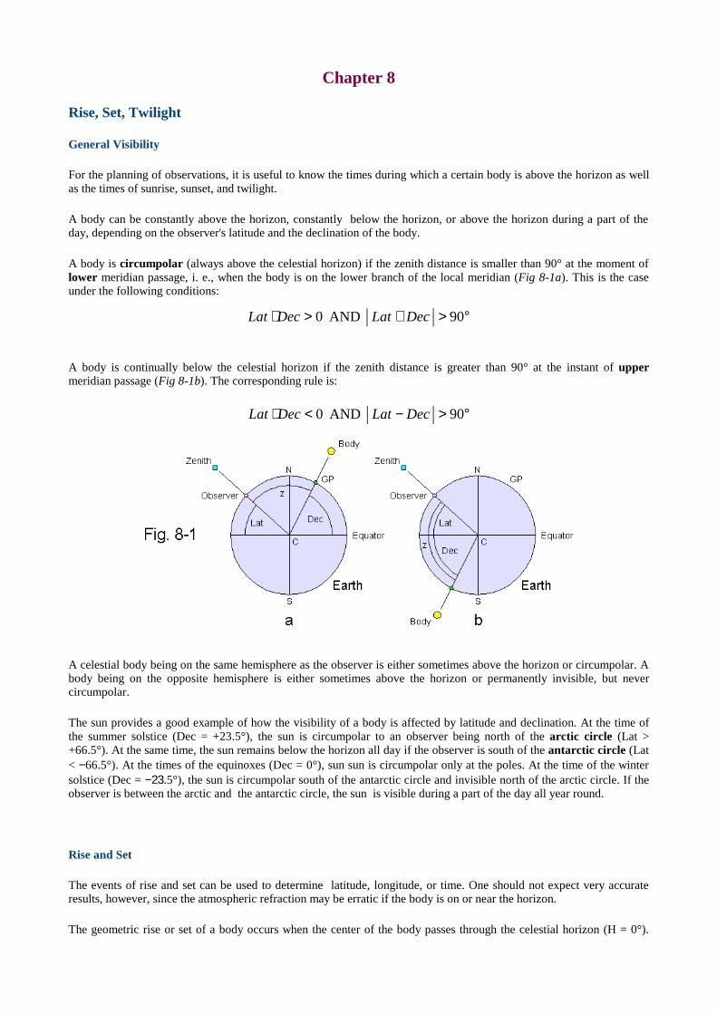
Chapter 8
Rise, Set, Twilight
General Visibility
For the planning of observations, it is useful to know the times during which a certain body is above the horizon as wellas the times of sunrise, sunset, and twilight.
A body can be constantly above the horizon, constantly below the horizon, or above the horizon during a part of theday, depending on the observer's latitude and the declination of the body.
A body is circumpolar (always above the celestial horizon) if the zenith distance is smaller than 90° at the moment oflower meridian passage, i. e., when the body is on the lower branch of the local meridian (Fig 8-1a). This is the caseunder the following conditions:
A body is continually below the celestial horizon if the zenith distance is greater than 90° at the instant of uppermeridian passage (Fig 8-1b). The corresponding rule is:
A celestial body being on the same hemisphere as the observer is either sometimes above the horizon or circumpolar. Abody being on the opposite hemisphere is either sometimes above the horizon or permanently invisible, but nevercircumpolar.
The sun provides a good example of how the visibility of a body is affected by latitude and declination. At the time ofthe summer solstice (Dec = +23.5°), the sun is circumpolar to an observer being north of the arctic circle (Lat >+66.5°). At the same time, the sun remains below the horizon all day if the observer is south of the antarctic circle (Lat< −66.5°). At the times of the equinoxes (Dec = 0°), sun sun is circumpolar only at the poles. At the time of the wintersolstice (Dec = −23.5°), the sun is circumpolar south of the antarctic circle and invisible north of the arctic circle. If theobserver is between the arctic and the antarctic circle, the sun is visible during a part of the day all year round.
Rise and Set
The events of rise and set can be used to determine latitude, longitude, or time. One should not expect very accurateresults, however, since the atmospheric refraction may be erratic if the body is on or near the horizon.
The geometric rise or set of a body occurs when the center of the body passes through the celestial horizon (H = 0°).
°>+>⋅ 90AND0 DecLatDecLat
°>−<⋅ 90AND0 DecLatDecLat
Due to the influence of atmospheric refraction, all bodies except the moon appear above the visible and sensible horizonat this instant. The moon is not visible at the moment of her geometric rise or set since the depressing effect of thehorizontal parallax (∼1°) is greater than the elevating effect of atmospheric refraction.
The approximate apparent altitudes (referring to the sensible horizon) at the moment of the astronomical rise or set are:
Sun (lower limb): 15'
Stars: 29'
Planets: 29' − HP
When measuring these altitudes with reference to the sea horizon, we have to add the dip of horizon (chapter 2) to theabove values. For example, the altitude of the lower limb of the rising or setting sun is approx. 20' if the height of eye is8m.
We begin with the well-known altitude formula (see chapter 4), substituting the meridian angle, t, for the local hourangle (see chapter 3). We can do this since the trigonometric functions of t are equal to those of the corresponding LHA.
Solving the equation for t, we get :
The equation has no solution if the argument of the inverse cosine is smaller than −1 or greater than 1. In the first case,the body is circumpolar, in the latter case, the body remains continuously below the horizon. Otherwise, the arccosfunction returns values in the range from 0°through 180°.
Due to the ambiguity of the arccos function, the equation has two solutions, one for rise and one for set. For thecalculations below, we have to observe the following rules:
If the body is rising (body eastward from the observer), t is treated as a negative quantity.
If the body is setting (body westward from the observer), t is treated as a positive quantity.
If we know our latitude and the time of rise or set, we can calculate our longitude:
GHA is the Greenwich hour angle of the body at the moment of rise or set. The sign of t has to be observed carefully(see above). If the resulting longitude is smaller than −180°, we add 360°.
Knowing our position, we can calculate the times of sunrise and sunset:
[ ] [ ]EoT
LontGMT setSurise −°−°±=
151512/
tDecLatDecLatH coscoscossinsin0sin ⋅⋅+⋅==
DecLat
DecLatt
coscos
sinsincos
⋅⋅−=
( )DecLatt tantanarccos ⋅−=
GHAtLon −±=
The times of sunrise and sunset obtained with the above formula are not quite accurate since Dec and EoT are variable.Since we do not know the exact time of rise or set at the beginning, we have to use estimated values for Dec and EoTinitially. The time of rise or set can be improved by iteration (repeating the calculations with Dec and EoT at thecalculated time of rise or set). Further, the times thus calculated are influenced by the irregularities of atmosphericrefraction near the horizon. Therefore, a time error of ±2 minutes is not unusual.
Accordingly, we can calculate our longitude from the time of sunrise or sunset if we know our latitude:
Again, this is not a very precise method, and an error of several arcminutes in longitude is not unlikely.
Knowing our longitude, we are able to determine our approximate latitude from the time of sunrise or sunset:
In navigation, rise and set are defined as the moments when the upper limb of a body crosses the visible horizon.These events can be observed without a sextant. Now, we have to take into account the effects of refraction, horizontalparallax, dip, and semidiameter. These quantities determine the altitude (Ho) of a body with respect to the celestialhorizon at the instant of the visible rise or set.
According to the Nautical Almanac, the refraction for a body being on the sensible horizon, RH, is approximately (!) 34'.
When observing the upper limb of the sun, we get:
Ho is negative. If we refer to the upper limb of the sun and the sensible horizon (Dip=0), the meridian angle at the timeof sunrise or sunset is:
Azimuth and Amplitude
The azimuth angle of a rising or setting body is calculated with the azimuth formula (see chapter 4):
DecLat
DecLatHot
coscos
sinsinsinarccos
⋅⋅−=
DipRSDHPHo H −−−=
DecLat
DecLatt
coscos
sinsin0145.0arccos
⋅⋅−−=
[ ] ( )EoTGMTtLon setSunrise −−⋅+±=° /1215
[ ] [ ] ( )EoTGMTLont setSunrise −−⋅−°=° /1215
−=
Dec
tLat
tan
cosarctan
DipDipHo −−≈−−−= '50'34'16'15.0
LatH
LatHDecAz
coscos
sinsinsinarccos
⋅⋅−=
With H=0, we get:
Az is +90° (rise) and −90° (set) if the declination of the body is zero, regardless of the observer's latitude. Accordingly,the sun rises in the east and sets in the west at the times of the equinoxes (geometric rise and set).
With Hcenter= −50' (upper limb of the sun on the sensible horizon), we have:
The true azimuth of the rising or setting body is:
The azimuth of a body at the moment of rise or set can be used to find the magnetic declination at the observer's position(compare with chapter 13).
The horizontal angular distance of the rising/setting body from the east/west point on the horizon is called amplitudeand can be calculated from the azimuth. An amplitude of E45°N, for instance, means that the body rises 45° north of theeast point on the horizon.
Twilight
At sea, twilight is important for the observation of stars and planets since it is the only time when these bodies and thehorizon are visible. By definition, there are three kindsof twilight. The altitude, H, refers to the center of the sun and thecelestial horizon and marks the beginning (morning) and the end (evening) of the respective twilight.
Civil twilight: H = −6°
Nautical twilight: H = −12°
Astronomical twilight: H = −18°
In general, an altitude of the sun between −3° and −9° is recommended for astronomical observations at sea (bestvisibility of brighter stars and sea horizon). However, exceptions to this rule are possible, depending on the actualweather conditions.
The meridian angle for the sun at −6° altitude (center) is:
Using this formula, we can find the approximate time for our observations (in analogy to sunrise and sunset).
DecLat
DecLatt
coscos
sinsin10453.0arccos
⋅⋅−−=
Lat
DecAz
cos
sinarccos=
Lat
LatDecAz
cos9999.0
sin0145.0sinarccos
⋅⋅+=
>−°≤
=0sinif360
0sinif
tAz
tAzAzN

As mentioned above, the simultaneous observation of stars and the horizon is possible during a limited time intervalonly.
To calculate the length of this interval, ∆T, we use the altitude formula and differentiate sin H with respect to themeridian angle, t:
Substituting cosH.dH for d(sinH) and solving for dt, we get the change in the meridian angle, dt, as a function of achange in altitude, dH:
With H = −6° and dH = 6° (H = −3°...−9°), we get:
Converting the change in the meridian angle to a time span (measured in minutes) and ignoring the sign, the equation isstated as:
The shortest possible time interval for our observations (Lat = 0, Dec = 0, t = 96°) lasts approx. 24 minutes. As theobserver moves northward or southward from the equator, cos Lat and sin t decrease (t>90°). Accordingly, the durationof twilight increases. When t is 0° or 180°, ∆T is infinite.
This is in accordance with the well-known fact that twilight is shortest in equatorial regions and longest in polar regions.
We would obtain the same result when calculating t for H = −3° and H = −9°, respectively:
The Nautical Almanac provides tabulated values for the times of sunrise, sunset, civil twilight and nautical twilight forlatitudes between −60° and +72° (referring to an observer being at the Greenwich meridian). In addition, times ofmoonrise and moonset are given.
( )tDecLat
td
Hdsincoscos
sin ⋅⋅−=
( ) tdtDecLatHd ⋅⋅⋅−= sincoscossin
HdtDecLat
Htd ⋅
⋅⋅−=
sincoscos
cos
[ ]tDecLat
tsincoscos
97.5
⋅⋅−≈°∆
[ ]tDecLat
mTsincoscos
24
⋅⋅≈∆
[ ] [ ] [ ]( )°−°⋅=∆ °−°− 394 ttmT

Chapter 9
Geodetic Aspects of Celestial Navigation
The Ellipsoid
Celestial navigation is based upon the assumption that the earth is a sphere and, consequently, on the laws of sphericaltrigonometry. In reality, the shape of the earth is rather irregular and approximates an oblate spheroid (ellipsoid)resulting from two forces, gravitation and centrifugal force, acting on the viscous body of the earth. While gravitationalone would force the earth to assume the shape of a sphere, the state of lowest potential energy, the centrifugal forcecaused by the earth's rotation contracts the earth along the polar axis (axis of rotation) and stretches it along the plane ofthe equator. The local vector sum of both forces is called gravity.
A number of reference ellipsoids are in use to describe the shape of the earth, for example the World Geodetic System(WGS) ellipsoid of 1984. The following considerations refer to the ellipsoid model of the earth which is sufficientfor most navigational purposes. Fig.9-1 shows a meridional section of the ellipsoid.
Earth data (WGS 84 ellipsoid) :
Equatorial radius re 6378137.0 m
Polar radius rp 6356752.3142 m
Flattening (re- rp) / re 1/298.25722
Due to the flattening of the earth, we have to distinguish between geographic and geocentric latitude which would bethe same if the earth were a sphere. The geographic (geodetic) latitude of a given position, Lat, is the angle formed bythe local normal (perpendicular) to the adopted ellipsoid and the plane of the equator. The geocentric latitude, Lat', isthe angle formed by the local radius vector and the plane of the equator. Geographic and geocentric latitude areinterrelated as follows:
Geographic and geocentric latitude are equal at the poles and on the equator. At all other places, the geocentric latitude,Lat', is smaller than the geographic latitude, Lat. As with the spherical earth model, geographic and geocentric longitudeare equal. Maps are always based upon geographic (geodetic) coordinates.
Latr
rLat
e
p tan'tan2
2
⋅=

In the following, we will discuss the effects of the oblateness (flattening) of the earth on celestial navigation. Altitudes(or zenith distances) measured by the navigator always refer to the local plumb line which aligns itself with gravity andpoints to the astronomical zenith.
Even the visible sea horizon correlates with the astronomical zenith since the water surface is perpendicular to the localplumb line. Under the assumption of a homogeneous mass distribution throughout the ellipsoid, the plumb line coincideswith the local normal to the ellipsoid which points to the geodetic zenith. Thus, astronomical and geodetic zenith areidentical.
The geocentric zenith is defined as the point where the extended local radius vector of the earth intersects the celestialsphere. The angular distance of the astronomical (geodetic) zenith from the geocentric zenith is called angle of thevertical, v. The angle of the vertical is a function of the geographic latitude. The following formula was proposed bySmart [9]:
The coefficients of the formula have been adapted to the proportions of the WGS 84 ellipsoid.
The angle of the vertical at a given position equals the difference between geographic and geocentric latitude (Fig. 9-1):
The maximum value of v, occurring at 45° geographic latitude, is approx. 11.5'. Thus, the geocentric latitude of anobserver being at 45°geographic latitude is only 44° 48.5'. This difference is not negligible. Therefore, the navigator hasto know if the coordinates of a fix obtained by astronomical observations are geographic or geocentric. Altitudes aremeasured with respect to the sea horizon or an artificial horizon. Both correlate with the local plumb line which points tothe astronomical zenith. Thus, the latter is the only reference available to the navigator. As demonstrated in Fig. 9-1, thealtitude of the celestial north pole, PN, (corrected altitude of Polaris) with respect to the geoidal horizon equals the
geographic, not the geocentric latitude. A noon latitude, being the sum or difference of the (geocentric) declination andthe zenith distance with respect to the astronomical zenith would give the same result.
Latitudes obtained by celestial observations are geographic latitudes since the navigator measures altitudes withrespect to the local astronomical zenith (directly or indirectly).
It is further important to know if the oblateness of the earth causes significant errors due to the fact that calculations ofcelestial navigation are based on a spherical earth model. According to the above values for polar radius and equatorialradius of the earth, the great circle distance of 1' is 1.849 km at the poles and 1.855 km at the equator. This smalldifference does not produce a significant error when plotting lines of position. It is therefore sufficient to use theadopted mean value (1 nautical mile = 1.852 km). However, when calculating the great circle distance (see chapter 11)of two locations thousands of nautical miles apart, the error caused by the oblateness of the earth can increase to severalnautical miles. If extraordinary precision is required, the formulas for geodetic distance given in [2] should be used.
The Parallax of the Moon
Due to the oblateness of the earth, the distance between geoidal and celestial horizon is not constant but can assume anyvalue between rp and re, depending on the observer's latitude. This has a measurable effect on the parallax of the moon
since tabulated values for HP refer to the equatorial radius, re. The parallax of the moon is further affected by the
displacement of the plumb line from the earth's center. A correction formula compensating both effects is given inchapter 2. The asymmetry of the plumb line with respect to the earth's center even causes a small (negligible) parallax inazimuth unless the moon is on the local meridian. In the following, we will calculate the effects of the oblateness of theearth on the parallax of the moon with the exact formulas of spherical astronomy [9]. For practical navigation, thesimplified correction formulas given in chapter 2 are accurate enough. Fig. 9-2 shows a projection of the astronomicalzenith, Za, the geocentric zenith, Zc, and the geographic position of the moon, M, on the celestial sphere, an imaginary
hollow sphere of infinite diameter with the earth at its center.
[ ] ( ) ( ) ( )LatLatLatv ⋅⋅+⋅⋅−⋅⋅≈ 6sin026.04sin163.12sin666.692''
'LatLatv −=
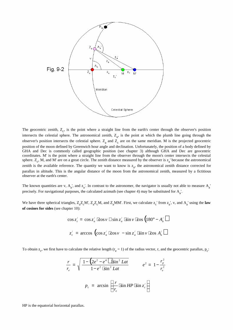
The geocentric zenith, Zc, is the point where a straight line from the earth's center through the observer's position
intersects the celestial sphere. The astronomical zenith, Za, is the point at which the plumb line going through the
observer's position intersects the celestial sphere. Za and Zc are on the same meridian. M is the projected geocentric
position of the moon defined by Greenwich hour angle and declination. Unfortunately, the position of a body defined byGHA and Dec is commonly called geographic position (see chapter 3) although GHA and Dec are geocentriccoordinates. M' is the point where a straight line from the observer through the moon's center intersects the celestialsphere. Zc, M, and M' are on a great circle. The zenith distance measured by the observer is za' because the astronomical
zenith is the available reference. The quantity we want to know is za, the astronomical zenith distance corrected for
parallax in altitude. This is the angular distance of the moon from the astronomical zenith, measured by a fictitiousobserver at the earth's center.
The known quantities are v, Aa', and za'. In contrast to the astronomer, the navigator is usually not able to measure Aa'
precisely. For navigational purposes, the calculated azimuth (see chapter 4) may be substituted for Aa'.
We have three spherical triangles, ZaZcM', ZaZcM, and ZaMM'. First, we calculate zc' from za', v, and Aa' using the law
of cosines for sides (see chapter 10):
To obtain zc, we first have to calculate the relative length (re = 1) of the radius vector, r, and the geocentric parallax, pc:
HP is the equatorial horizontal parallax.
( )//// cossinsincoscosarccos aaac Avzvzz ⋅⋅−⋅=
⋅⋅= /sinsinarcsin c
ec zHP
r
rp
( )//// 180cossinsincoscoscos aaac Avzvzz −°⋅⋅+⋅=
( )2
22
22
242
1sin1
sin21
e
p
e r
re
Late
Latee
r
r −=⋅−
⋅−−=

The geocentric zenith distance corrected for parallax is:
Using the cosine formula again, we calculate Ac, the azimuth angle of the moon with respect to the geocentric zenith:
The astronomical zenith distance corrected for parallax is:
Thus, the parallax in altitude (astronomical) is:
The small angle between M and M', measured at Za, is the parallax in azimuth, paz:
Comparing the exact formulas with the simplified parallax formulas given in chapter 2 (including the correction for theoblateness of the earth), we will find very small differences in the observed altitude (small fractions of an arcsecond).These small differences are not measurable with the instruments of celestial navigation and can be neglected.
The parallax in azimuth does not exist when the moon is on the local meridian and is greatest when the moon ist east orwest of the observer. It is further greatest at medium latitudes (45°) and non-existant when the observer is at one of thepoles or on the equator (v = 0). Even under the most unfavourable conditions, the parallax in azimuth is only a fractionof an arcminute and therefore insignificant to celestial navigation.
Other celestial bodies do not require a correction for the oblateness of the earth since their parallaxes are verysmall compared with the parallax of the moon.
The Geoid
The earth is not exactly an oblate ellipsoid. The shape of the earth is more accurately described by the geoid, anequipotential surface of the earth's field of gravity. This surface has elevations and depressions caused by geographicfeatures and a non-uniform mass distribution (materials of different density). Elevations occur at local accumulations ofmatter (mountains, ore deposits), depressions at local deficiencies of matter (valleys, lakes, caverns). The elevation ordepression of each point of the geoid with respect to the ellipsoid is found by gravity measurement. At the flank of anelevation or depression of the geoid, the plumb line (the normal to the geoid) does not coincide with the normal to theellipsoid, and the astronomical zenith differs from the geodetic zenith. Thus, the astronomical latitude or longitude of aposition (obtained through astronomical observations) may slightly differ from the geographic (geodetic) latitude orlongitude. These differences are usually smaller than one arcminute, but greater local differenceshave been reported, forexample, in coastal waters with adjacent high mountains.
The errors caused by the irregular shape of the geoid are usually not relevant to celestial navigation at sea but areimportant to surveying and map-making where a higher degree of accuracy is required.
ccc pzz −= /
vz
vzzA
c
cac sinsin
coscoscosarccos
/
//
⋅⋅−
=
( )ccca Avzvzz cossinsincoscosarccos ⋅⋅+⋅=
/
/
sinsin
coscoscosarccos
aa
aacaz zz
zzpp
⋅⋅−=
aa zzPA −= /
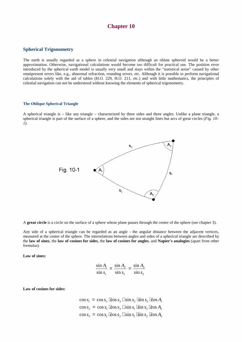
Chapter 10
Spher ical Tr igonometry
The earth is usually regarded as a sphere in celestial navigation although an oblate spheroid would be a betterapproximation. Otherwise, navigational calculations would become too difficult for practical use. The position errorintroduced by the spherical earth model is usually very small and stays within the "statistical noise" caused by otheromnipresent errors like, e.g., abnormal refraction, rounding errors, etc. Although it is possible to perform navigationalcalculations solely with the aid of tables (H.O. 229, H.O. 211, etc.) and with little mathematics, the principles ofcelestial navigation can not be understood without knowing the elements of spherical trigonometry.
The Oblique Spher ical Tr iangle
A spherical triangle is – like any triangle – characterized by three sides and three angles. Unlike a plane triangle, aspherical triangle is part of the surface of a sphere, and the sides are not straight lines but arcs of great circles (Fig. 10-1).
A great circle is a circle on the surface of a sphere whose plane passes through the center of the sphere (see chapter 3).
Any side of a spherical triangle can be regarded as an angle - the angular distance between the adjacent vertices,measured at the center of the sphere. The interrelations between angles and sides of a spherical triangle are described bythe law of sines, the law of cosines for sides, the law of cosines for angles, and Napier 's analogies (apart from otherformulas).
Law of sines:
Law of cosines for sides:
3
3
2
2
1
1
sin
sin
sin
sin
sin
sin
s
A
s
A
s
A ==
321213
231312
132321
cossinsincoscoscos
cossinsincoscoscos
cossinsincoscoscos
Asssss
Asssss
Asssss
⋅⋅+⋅=⋅⋅+⋅=⋅⋅+⋅=
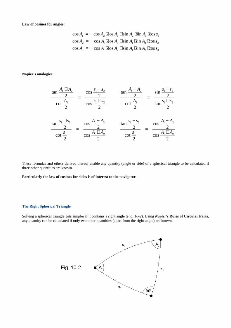
Law of cosines for angles:
Napier 's analogies:
These formulas and others derived thereof enable any quantity (angle or side) of a spherical triangle to be calculated ifthree other quantities are known.
Par ticular ly the law of cosines for sides is of interest to the navigator .
The Right Spher ical Tr iangle
Solving a spherical triangle gets simpler if it contains a right angle (Fig. 10-2). Using Napier's Rules of Circular Par ts,any quantity can be calculated if only two other quantities (apart from the right angle) are known.
321213
231312
132321
cossinsincoscoscos
cossinsincoscoscos
cossinsincoscoscos
sAAAAA
sAAAAA
sAAAAA
⋅⋅+⋅−=⋅⋅+⋅−=⋅⋅+⋅−=
2cos
2cos
2cot
2tan
2cos
2cos
2cot
2tan
2sin
2sin
2cot
2tan
2cos
2cos
2cot
2tan
21
21
3
21
21
21
3
21
21
21
3
21
21
21
3
21
AA
AA
s
ss
AA
AA
s
ss
ss
ss
A
AA
ss
ss
A
AA
+
−
=
−
+
−
=
+
+
−
=
−
+
−
=
+
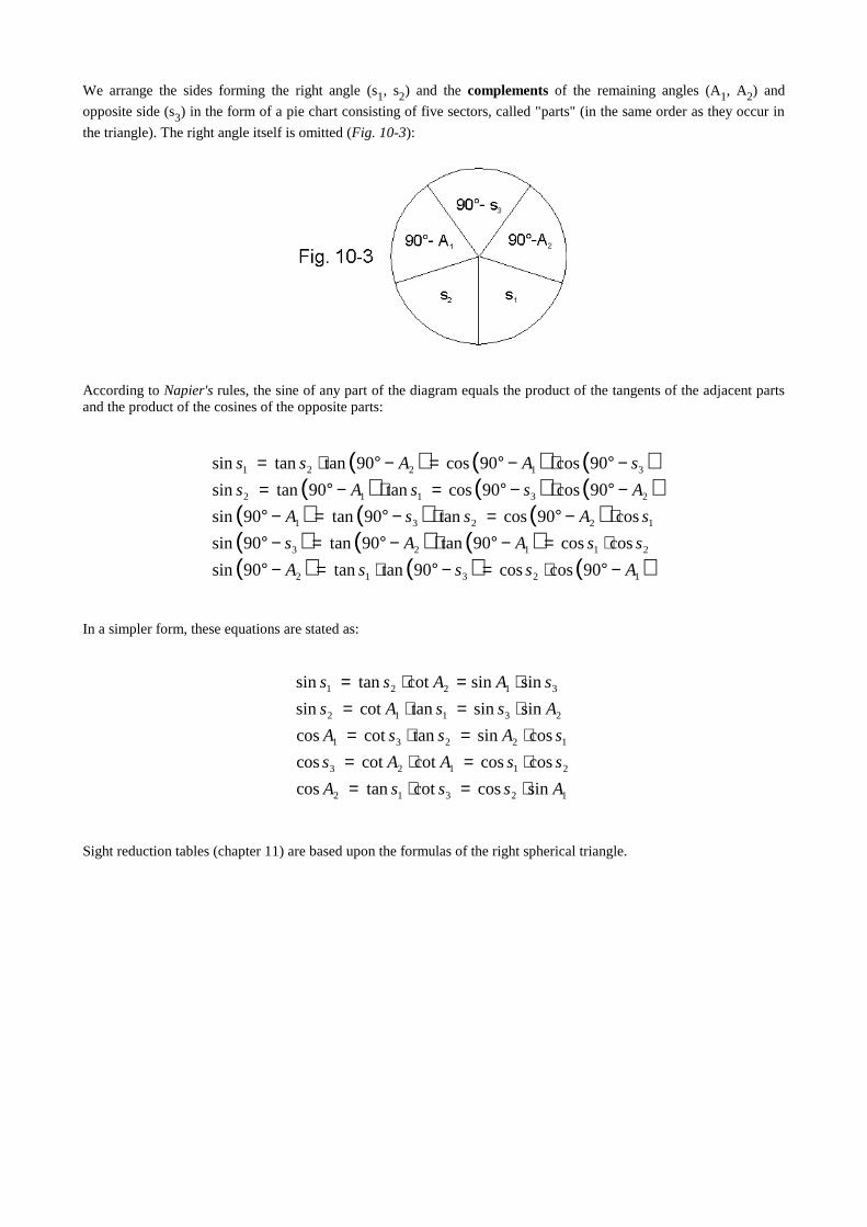
We arrange the sides forming the right angle (s1, s2) and the complements of the remaining angles (A1, A2) and
opposite side (s3) in the form of a pie chart consisting of five sectors, called "parts" (in the same order as they occur in
the triangle). The right angle itself is omitted (Fig. 10-3):
According to Napier's rules, the sine of any part of the diagram equals the product of the tangents of the adjacent partsand the product of the cosines of the opposite parts:
In a simpler form, these equations are stated as:
Sight reduction tables (chapter 11) are based upon the formulas of the right spherical triangle.
( ) ( ) ( )( ) ( ) ( )
( ) ( ) ( )( ) ( ) ( )( ) ( ) ( )12312
21123
12231
23112
31221
90coscos90tantan90sin
coscos90tan90tan90sin
cos90costan90tan90sin
90cos90costan90tansin
90cos90cos90tantansin
AsssA
ssAAs
sAssA
AssAs
sAAss
−°⋅=−°⋅=−°⋅=−°⋅−°=−°⋅−°=⋅−°=−°−°⋅−°=⋅−°=−°⋅−°=−°⋅=
12312
21123
12231
23112
31221
sincoscottancos
coscoscotcotcos
cossintancotcos
sinsintancotsin
sinsincottansin
AsssA
ssAAs
sAssA
AssAs
sAAss
⋅=⋅=⋅=⋅=⋅=⋅=
⋅=⋅=⋅=⋅=

Chapter 11
The Navigational Triangle
The navigational triangle, the basis of all common sight reduction procedures, is the (usually oblique) sphericaltriangle on the earth's surface formed by the north pole, N, the observer's assumed position, AP, and the geographicposition of the celestial object, GP, at the time of observation (Fig. 11-1).
When using the intercept method, the latitude of the assumed position, LatAP, the declination of the observed celestial
body, Dec, and the local hour angle, LHA, or the meridian angle, t, (calculated from the longitude of AP and the GHAof the object), are initially known to the observer.
The first step is calculating the side z of the navigational triangle by using the law of cosines for sides:
Since cos (90°-x) equals sin x and vice versa, the equation can be written in a simpler form:
The side z is not only the great circle distance between AP and GP but also the zenith distance of the celestial objectand the radius of the circle of equal altitude (see chapter 1).
Substituting the altitude H for z, we get:
Solving the equation for H leads to the altitude formula known from chapter 4:
( ) ( ) ( ) ( ) LHADecLatDecLatz APAP cos90sin90sin90cos90coscos ⋅−°⋅−°+−°⋅−°=
LHADecLatDecLatz APAP coscoscossinsincos ⋅⋅+⋅=
LHADecLatDecLatH APAP coscoscossinsinsin ⋅⋅+⋅=
( )LHADecLatDecLatH APAP coscoscossinsinarcsin ⋅⋅+⋅=

The azimuth angle of the observed body is also calculated by means of the law of cosines for sides:
Using the altitude, which has been calculated already, instead of the zenith distance, results in the following equation:
Solving the equation for Az finally yields the azimuth formula from chapter 4:
The resulting azimuth angle is always in the range of 0°... 180° and therefore not necessarily identical with the trueazimuth, AzN (0°... 360° clockwise from true north) commonly used in navigation. In all cases where sin LHA is
negative (GP east of AP) , Az equals AzN. Otherwise (sin LHA positive, GP westward from AP , as shown in Fig. 11-1),
AzN is obtained by subtracting Az from 360°.
When using Sumner's method, z (or H), Dec, and LatAP (the assumed latitude) are initially known, and LHA (or t) is the
quantity to be calculated.
Again, the law of cosines for sides can be applied:
The obtained LHA (or t) is then processed as described in chapter 4.
When observing a celestial body at the time of meridian passage, the local hour angle is zero, and the navigationaltriangle becomes infinitesimally narrow. In this special case, the formulas of spherical trigonometry are not needed, andthe sides of the spherical triangle can be calculated by simple addition or subtraction.
( ) ( ) ( ) AzzLatzLatDec APAP cossin90sincos90cos90cos ⋅⋅−°+⋅−°=−°
AzzLatzLatDec APAP cossincoscossinsin ⋅⋅+⋅=
AzHLatHLatDec APAP coscoscossinsinsin ⋅⋅+⋅=
HLat
HLatDecAz
AP
AP
coscos
sinsinsinarccos
⋅⋅−=
( ) ( ) ( ) ( ) LHADecLatDecLatz APAP cos90sin90sin90cos90coscos ⋅−°⋅−°+−°⋅−°=
LHADecLatDecLatH APAP coscoscossinsinsin ⋅⋅+⋅=
DecLat
DecLatHLHA
AP
AP
coscos
sinsinsincos
⋅⋅−=
DecLat
DecLatHLHA
AP
AP
coscos
sinsinsinarccos
⋅⋅−=
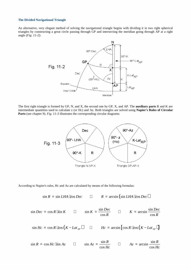
The Divided Navigational Tr iangle
An alternative, very elegant method of solving the navigational triangle begins with dividing it in two right sphericaltriangles by constructing a great circle passing through GP and intersecting the meridian going through AP at a rightangle (Fig. 11-2):
The first right triangle is formed by GP, N, and X, the second one by GP, X, and AP. The auxiliary par ts R and K areintermediate quantities used to calculate z (or Hc) and Az. Both triangles are solved using Napier 's Rules of CircularPar ts (see chapter 9). Fig. 11-3 illustrates the corresponding circular diagrams:
According to Napier's rules, Hc and Az are calculated by means of the following formulas:
( )DecLHARDecLHAR cossinarcsincossinsin ⋅=⇒⋅=
R
DecK
R
DecKKRDec
cos
sinarcsin
cos
sinsinsincossin =⇒=⇒⋅=
( ) ( )[ ]APAP LatKRHcLatKRHc −⋅=⇒−⋅= coscosarcsincoscossin
Hc
RAz
Hc
RAzAzHcR
cos
sinarcsin
cos
sinsinsincossin =⇒=⇒⋅=

To obtain the true azimuth, AzN (0°... 360°), the following rules have to be applied:
If the sine of LHA is negative, enter the above formulas with the explementary angle, 360°-LHA, instead of LHA.
The divided navigational triangle is of considerable importance since it forms the theoretical background for a numberof sight reduction tables, e.g., the Ageton Table.
Using the secant and cosecant function (sec x = 1/cos x, csc x = 1/sin x) and substituting the meridian angle, t, for LHA,the equations for the divided navigational triangle are stated as:
In logarithmic form, these equations are stated as:
Having the logarithms of the secants and cosecants of angles available in the form of a suitable table, we can solve asight by a sequence of simple additions and subtractions (beside converting the angles to their corresponding log secantsand log cosecants and vice versa). Apart from the table itself, the only tools required are a sheet of paper and a pencil.
The Ageton Table (H.O. 211), first published in 1931, is based upon the above formulas and provides a very efficientarrangement of angles and their log secants and log cosecants on 36 pages as well as step by step instructions for use.
Sight reduction tables were developed many years before the invention of electronic calculators in order to simplifycalculations necessary to reduce a sight. Still today, sight reduction tables are preferred by people who do not want todeal with the formulas of spherical trigonometry. Moreover, they provide a valuable backup method if electronic devicesfail.
A modified version of the Ageton Table is available at: http://www.umland.onlinehome.de/page3.htm
>>−°<>+°<<−°><
=
AP
AP
AP
AP
N
LatDecLHAAz
LatDecLHAAz
LatDecLHAAz
LatDecLHAAz
Az
AND0sinif360
AND0sinif180
AND0sinif180
AND0sinif
DectR seccsccsc ⋅=
R
DecK
sec
csccsc =
( )LatKRHc −⋅= secseccsc
Hc
RAz
sec
csccsc =
DectR seclogcsclogcsclog +=
RDecK seclogcsclogcsclog −=
( )LatKRHc −+= seclogseclogcsclog
HcRAz seclogcsclogcsclog −=
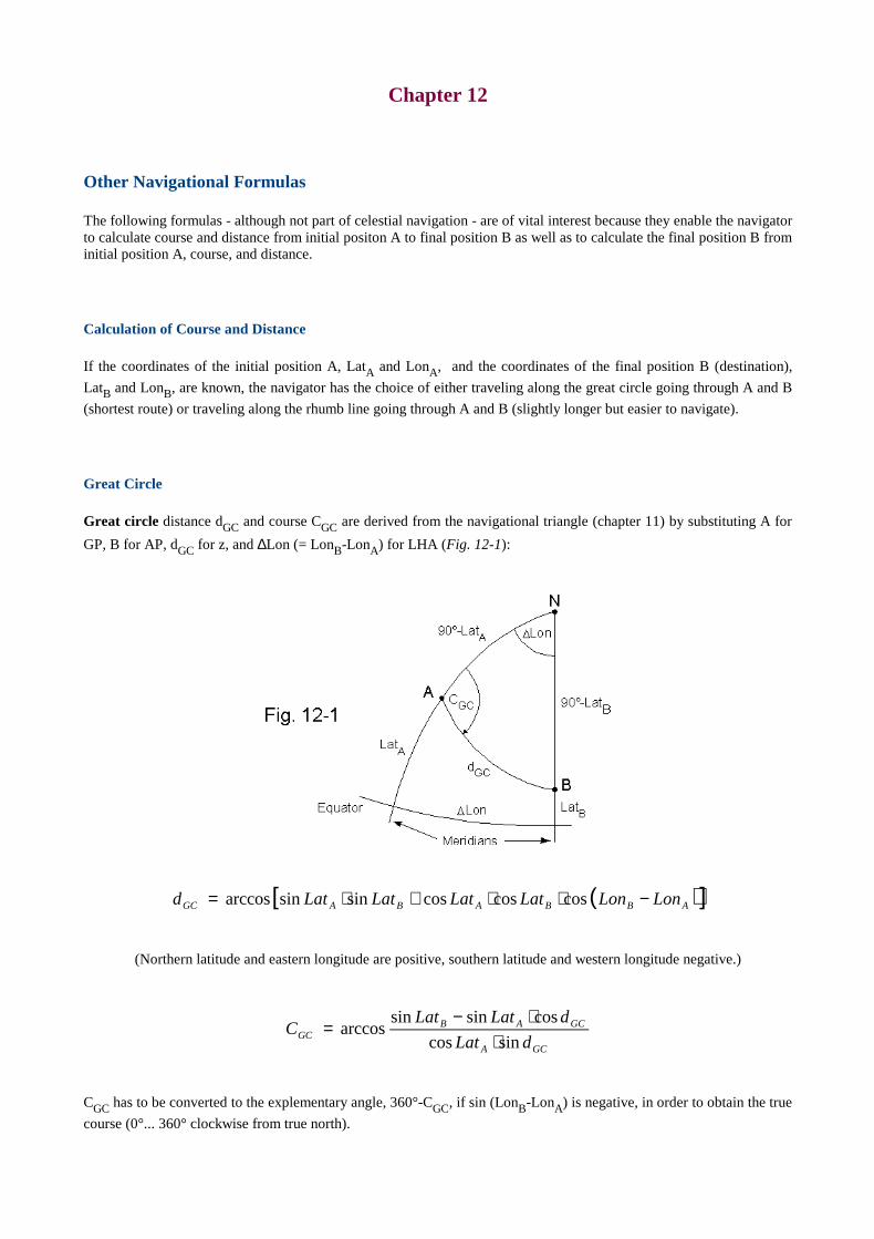
Chapter 12
Other Navigational Formulas
The following formulas - although not part of celestial navigation - are of vital interest because they enable the navigatorto calculate course and distance from initial positon A to final position B as well as to calculate the final position B frominitial position A, course, and distance.
Calculation of Course and Distance
If the coordinates of the initial position A, LatA and LonA, and the coordinates of the final position B (destination),
LatB and LonB, are known, the navigator has the choice of either traveling along the great circle going through A and B
(shortest route) or traveling along the rhumb line going through A and B (slightly longer but easier to navigate).
Great Circle
Great circle distance dGC and course CGC are derived from the navigational triangle (chapter 11) by substituting A for
GP, B for AP, dGC for z, and ∆Lon (= LonB-LonA) for LHA (Fig. 12-1):
(Northern latitude and eastern longitude are positive, southern latitude and western longitude negative.)
CGC has to be converted to the explementary angle, 360°-CGC, if sin (LonB-LonA) is negative, in order to obtain the true
course (0°... 360° clockwise from true north).
( )[ ]ABBABAGC LonLonLatLatLatLatd −⋅⋅+⋅= coscoscossinsinarccos
GCA
GCABGC dLat
dLatLatC
sincos
cossinsinarccos
⋅⋅−
=
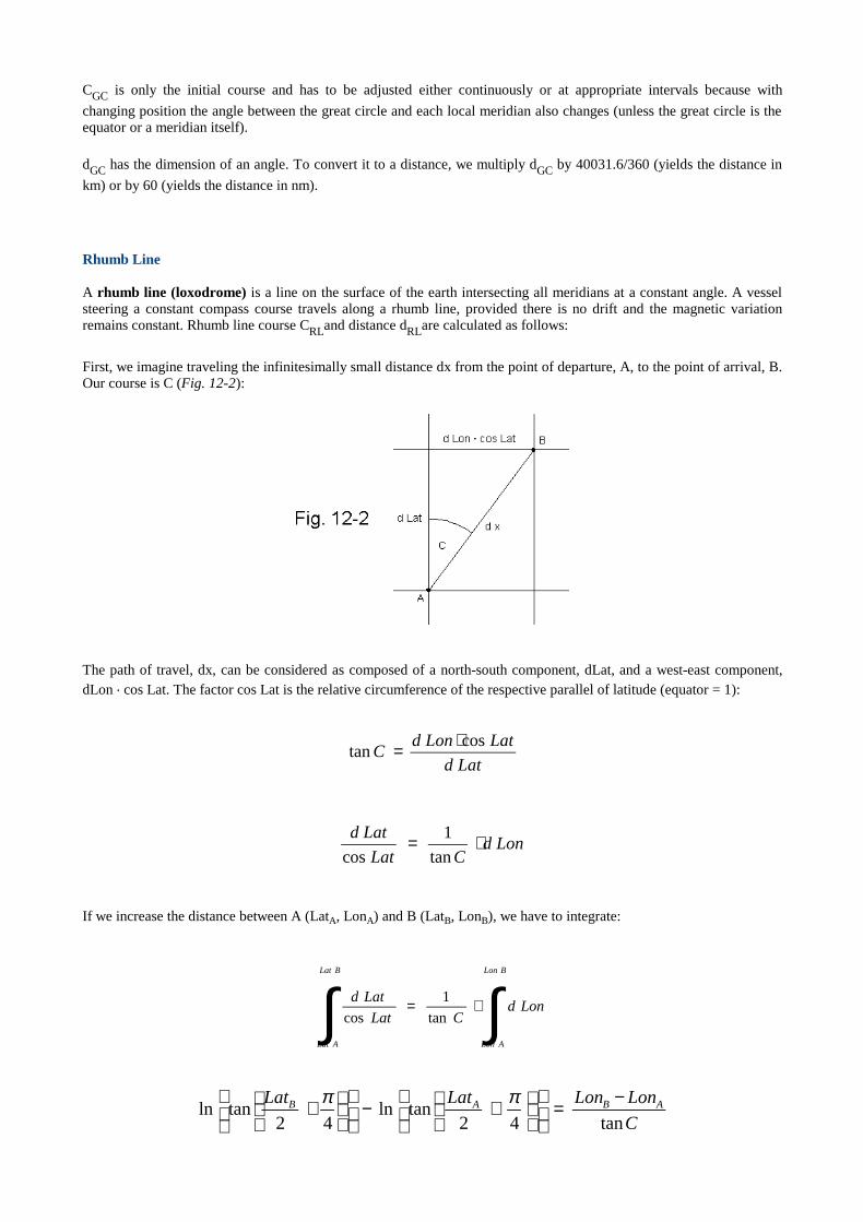
CGC is only the initial course and has to be adjusted either continuously or at appropriate intervals because with
changing position the angle between the great circle and each local meridian also changes (unless the great circle is theequator or a meridian itself).
dGC has the dimension of an angle. To convert it to a distance, we multiply dGC by 40031.6/360 (yields the distance in
km) or by 60 (yields the distance in nm).
Rhumb Line
A rhumb line (loxodrome) is a line on the surface of the earth intersecting all meridians at a constant angle. A vesselsteering a constant compass course travels along a rhumb line, provided there is no drift and the magnetic variationremains constant. Rhumb line course CRLand distance dRLare calculated as follows:
First, we imagine traveling the infinitesimally small distance dx from the point of departure, A, to the point of arrival, B.Our course is C (Fig. 12-2):
The path of travel, dx, can be considered as composed of a north-south component, dLat, and a west-east component,dLon . cos Lat. The factor cos Lat is the relative circumference of the respective parallel of latitude (equator = 1):
If we increase the distance between A (LatA, LonA) and B (LatB, LonB), we have to integrate:
Latd
LatLondC
costan
⋅=
LondCLat
Latd ⋅=tan
1
cos
∫∫ ⋅=
BLon
ALon
BLat
ALat
LondCLat
Latd
tan
1
cos
C
LonLonLatLat ABAB
tan42tanln
42tanln
−=
+−
+ ππ
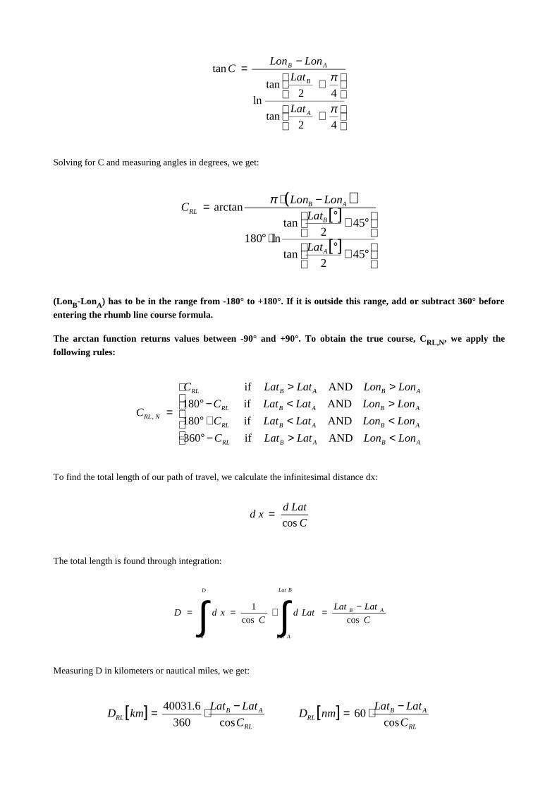
Solving for C and measuring angles in degrees, we get:
(LonB-LonA) has to be in the range from -180° to +180°. I f it is outside this range, add or subtract 360° before
enter ing the rhumb line course formula.
The arctan function returns values between -90° and +90°. To obtain the true course, CRL,N, we apply the
following rules:
To find the total length of our path of travel, we calculate the infinitesimal distance dx:
The total length is found through integration:
Measuring D in kilometers or nautical miles, we get:
( )[ ]
[ ]
°+°
°+°
⋅°
−⋅=
452
tan
452
tanln180
arctan
A
B
ABRL
Lat
LatLonLon
Cπ
+
+
−=
42tan
42tan
ln
tan
π
π
A
B
AB
Lat
Lat
LonLonC
<>−°<<+°><−°>>
=
ABABRL
ABABRL
ABABRL
ABABRL
NRL
LonLonLatLatC
LonLonLatLatC
LonLonLatLatC
LonLonLatLatC
C
ANDif360
ANDif180
ANDif180
ANDif
,
C
Latdxd
cos=
∫∫ −=⋅==
BLat
ALat
AB
D
C
LatLatLatd
CxdD
coscos
1
0
[ ] [ ]RL
ABRL
RL
ABRL C
LatLatnmD
C
LatLatkmD
cos60
cos360
6.40031 −⋅=−⋅=

If both positions have the same latitude, the distance can not be calculated using the above formulas. In this case, thefollowing formulas apply (CRL is either 90° or 270°.):
Mid latitude
Since the rhumb line course formula is rather complicated, it ismostly replaced by the mid latitude formula in everydaynavigation. This is an approximation giving good results as long as the distance between both positions is not too largeand both positions are far enough from the poles.
Mid latitude course:
The true course is obtained by applying the same rules to CMLas to the rhumb line course CRL.
Mid latitude distance:
If CML = 90° or CML = 270°, apply the following formulas:
Dead Reckoning
Dead reckoning is the navigational term for calculating one's new position B (dead reckoning position, DRP) fromthe previous position A, course C, and distance d (calculated from the vessel's average speed and time elapsed). Sincedead reckoning can only yield an approximate position (due to the influence of drift, etc.), the mid latitude methodprovidessufficient accuracy. On land, dead reckoning ismore difficult than at sea since it is usually not possible to steera constant course (apart from driving in large, entirely flat areas like, e.g., salt flats). At sea, the DRP is usually used tochoose an appropriate (near-by) AP. If celestial observations are not possible and electronic navigation aids are notavailable, dead reckoning may be the only way of keeping track of one's position.
Calculation of new latitude:
Calculation of new longitude:
If the resulting longitude exceeds 180°, subtract 360°. If it exceeds -180°, add 360°.
[ ] ( ) [ ] ( ) LatLonLonnmDLatLonLonkmD ABRLABRL cos60cos360
6.40031 ⋅−⋅=⋅−⋅=
[ ] [ ]ML
ABML
ML
ABML C
LatLatnmd
C
LatLatkmd
cos60
cos360
6.40031 −⋅=−⋅=
[ ] ( ) [ ] ( ) LatLonLonnmdLatLonLonkmd ABMLABML cos60cos360
6.40031 ⋅−⋅=⋅−⋅=
[ ] [ ] [ ] [ ] [ ] [ ]C
nmdLatLatCkmdLatLat ABAB cos
60cos
6.40031
360 ⋅+°=°⋅⋅+°=°
[ ] [ ] [ ] [ ] [ ] [ ]M
ABM
AB Lat
CnmdLonLon
Lat
CkmdLonLon
cos
sin
60cos
sin
6.40031
360 ⋅+°=°⋅⋅+°=°
2cosarctan BA
MAB
ABMML
LatLatLat
LatLat
LonLonLatC
+=
−−
⋅=
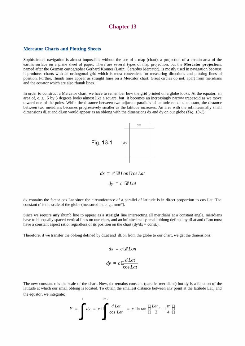
Chapter 13
Mercator Charts and Plotting Sheets
Sophisticated navigation is almost impossible without the use of a map (chart), a projection of a certain area of theearth's surface on a plane sheet of paper. There are several types of map projection, but the Mercator projection,named after the German cartographer Gerhard Kramer (Latin: Gerardus Mercator), is mostly used in navigation becauseit produces charts with an orthogonal grid which is most convenient for measuring directions and plotting lines ofposition. Further, rhumb lines appear as straight lines on a Mercator chart. Great circles do not, apart from meridiansand the equator which are also rhumb lines.
In order to construct a Mercator chart, we have to remember how the grid printed on a globe looks. At the equator, anarea of, e. g., 5 by 5 degrees looks almost like a square, but it becomes an increasingly narrow trapezoid as we movetoward one of the poles. While the distance between two adjacent parallels of latitude remains constant, the distancebetween two meridians becomes progressively smaller as the latitude increases. An area with the infinitesimally smalldimensions dLat and dLon would appear as an oblong with the dimensions dx and dy on our globe (Fig. 13-1):
dx contains the factor cos Lat since the circumference of a parallel of latitude is in direct proportion to cos Lat. Theconstant c' is the scale of the globe (measured in, e. g., mm/°).
Since we require any rhumb line to appear as a straight line intersecting all meridians at a constant angle, meridianshave to be equally spaced vertical lineson our chart, and an infinitesimally small oblong defined by dLat and dLon musthave a constant aspect ratio, regardless of its position on the chart (dy/dx = const.).
Therefore, if we transfer the oblong defined by dLat and dLon from the globe to our chart, we get the dimensions:
The new constant c is the scale of the chart. Now, dx remains constant (parallel meridians) but dy is a function of thelatitude at which our small oblong is located. To obtain the smallest distance between any point at the latitude LatP and
the equator, we integrate:
Latdcdy ⋅= '
LatLondcdx cos' ⋅⋅=
Lat
Latdcdy
cos⋅=
Londcdx ⋅=
+⋅=⋅== ∫ ∫ 42
tanlncos
0 0
πP
Y Lat
Latc
Lat
LatdcdyY
P
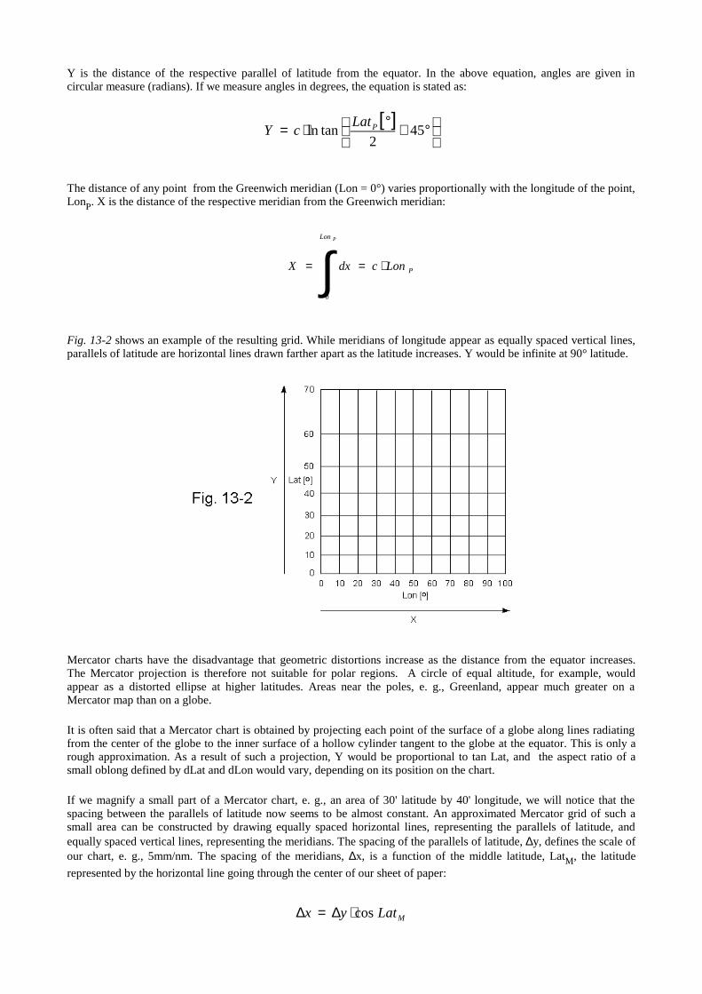
Y is the distance of the respective parallel of latitude from the equator. In the above equation, angles are given incircular measure (radians). If we measure angles in degrees, the equation is stated as:
The distance of any point from the Greenwich meridian (Lon = 0°) variesproportionally with the longitude of the point,LonP. X is the distance of the respective meridian from the Greenwich meridian:
Fig. 13-2 shows an example of the resulting grid. While meridians of longitude appear as equally spaced vertical lines,parallels of latitude are horizontal lines drawn farther apart as the latitude increases. Y would be infinite at 90° latitude.
Mercator charts have the disadvantage that geometric distortions increase as the distance from the equator increases.The Mercator projection is therefore not suitable for polar regions. A circle of equal altitude, for example, wouldappear as a distorted ellipse at higher latitudes. Areas near the poles, e. g., Greenland, appear much greater on aMercator map than on a globe.
It is often said that a Mercator chart is obtained by projecting each point of the surface of a globe along lines radiatingfrom the center of the globe to the inner surface of a hollow cylinder tangent to the globe at the equator. This is only arough approximation. As a result of such a projection, Y would be proportional to tan Lat, and the aspect ratio of asmall oblong defined by dLat and dLon would vary, depending on its position on the chart.
If we magnify a small part of a Mercator chart, e. g., an area of 30' latitude by 40' longitude, we will notice that thespacing between the parallels of latitude now seems to be almost constant. An approximated Mercator grid of such asmall area can be constructed by drawing equally spaced horizontal lines, representing the parallels of latitude, andequally spaced vertical lines, representing the meridians. The spacing of the parallels of latitude, ∆y, defines the scale ofour chart, e. g., 5mm/nm. The spacing of the meridians, ∆x, is a function of the middle latitude, LatM, the latitude
represented by the horizontal line going through the center of our sheet of paper:
[ ]
°+°⋅= 45
2tanln PLat
cY
∫ ⋅==
PLon
PLoncdxX
0
MLatyx cos⋅∆=∆
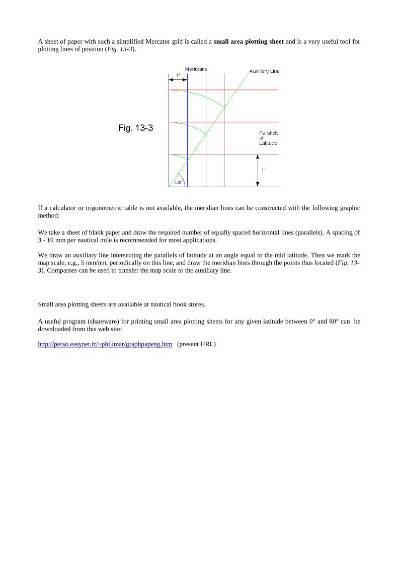
A sheet of paper with such a simplified Mercator grid is called a small area plotting sheet and is a very useful tool forplotting lines of position (Fig. 13-3).
If a calculator or trigonometric table is not available, the meridian lines can be constructed with the following graphicmethod:
We take a sheet of blank paper and draw the required number of equally spaced horizontal lines (parallels). A spacing of3 - 10 mm per nautical mile is recommended for most applications.
We draw an auxiliary line intersecting the parallels of latitude at an angle equal to the mid latitude. Then we mark themap scale, e.g., 5 mm/nm, periodically on this line, and draw the meridian lines through the points thus located (Fig. 13-3). Compasses can be used to transfer the map scale to the auxiliary line.
Small area plotting sheets are available at nautical book stores.
A useful program (shareware) for printing small area plotting sheets for any given latitude between 0° and 80° can bedownloaded from this web site:
http://perso.easynet.fr/~philimar/graphpapeng.htm (present URL)
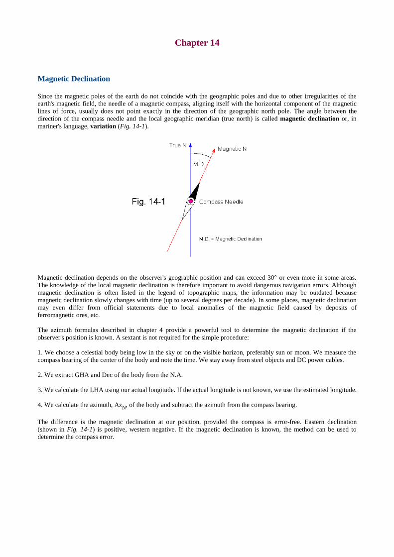
Chapter 14
Magnetic Declination
Since the magnetic poles of the earth do not coincide with the geographic poles and due to other irregularities of theearth's magnetic field, the needle of a magnetic compass, aligning itself with the horizontal component of the magneticlines of force, usually does not point exactly in the direction of the geographic north pole. The angle between thedirection of the compass needle and the local geographic meridian (true north) is called magnetic declination or, inmariner's language, variation (Fig. 14-1).
Magnetic declination depends on the observer's geographic position and can exceed 30° or even more in some areas.The knowledge of the local magnetic declination is therefore important to avoid dangerous navigation errors. Althoughmagnetic declination is often listed in the legend of topographic maps, the information may be outdated becausemagnetic declination slowly changes with time (up to several degrees per decade). In some places, magnetic declinationmay even differ from official statements due to local anomalies of the magnetic field caused by deposits offerromagnetic ores, etc.
The azimuth formulas described in chapter 4 provide a powerful tool to determine the magnetic declination if theobserver's position is known. A sextant is not required for the simple procedure:
1. We choose a celestial body being low in the sky or on the visible horizon, preferably sun or moon. We measure thecompass bearing of the center of the body and note the time. We stay away from steel objects and DC power cables.
2. We extract GHA and Dec of the body from the N.A.
3. We calculate the LHA using our actual longitude. If the actual longitude is not known, we use the estimated longitude.
4. We calculate the azimuth, AzN, of the body and subtract the azimuth from the compass bearing.
The difference is the magnetic declination at our position, provided the compass is error-free. Eastern declination(shown in Fig. 14-1) is positive, western negative. If the magnetic declination is known, the method can be used todetermine the compass error.

Chapter 15
Ephemerides of the Sun
The sun is probably the most frequently observed body in celestial navigation. Greenwich hour angle and declination ofthe sun as well as GHAAries and EoT can be calculated using the algorithms listed below. The formulas are relatively
simple and useful for navigational calculations with programmable pocket calculators (10 digits recommended).
First, the time variable, T, has to be calculated from year, month, and day. T is the number of days before or after Jan 1,2000, 12:00:00 GMT:
y is the number of the year (4 digits), m is the number of the month, and d the number of the day of the respectivemonth. GMT (UT) is Greenwich mean time in decimal format (e.g., 12h 30m 45s = 12.5125). For May 17, 1999,12:30:45 GMT, for example, T is -228.978646. The equation is valid from March 1, 1900 through February 28, 2100.
Mean anomaly of the sun*:
Mean longitude of the sun*:
True longitude of the sun*:
Obliquity of the ecliptic:
Declination of the sun:
Right ascension of the sun (in degrees)*:
GHAAries*:
5.730531249
275int12
9int75.1int367 −++
⋅+
++⋅−⋅= GMT
dmm
yyT
[ ] 472.29856003.0 −⋅=° Tg
[ ] 53938.799856474.0 −⋅=° TLM
[ ] T⋅⋅−=° −7104439.23ε
[ ] ( )εsinsinarcsin ⋅=° TLDec
[ ]
+
⋅⋅=°
T
T
LDec
LRA
coscos
sincosarctan2
ε
[ ] [ ] ( )ggLL MT ⋅⋅+⋅+°=° 2sin02.0sin915.1
[ ] 46062.100159856474.0 +⋅+⋅=° GMTTGHAAries
Greenwich hour angle of the sun*:
Equation of time:
*These quantities have to be within the range from 0° through 360°. If necessary, add or subtract 360° or multiplesthereof. This can be achieved using the following algorithm which is particularly useful for programmable calculators:
int(x) is the greatest integer smaller than x. For example, int(3.8) = 3, int(-2.2) = -3. The int function is called floor insome programming languages, e.g., JavaScript.
Accuracy
Unfortunately, no information on accuracy is given in the original literature [8]. Therefore, results have been cross-checked with Interactive Computer Ephemeris 0.51 (accurate to approx. 0.1'). Between the years 1900 and 2049, nodifference greater than ±0.5' for GHA and Dec was found with 100 dates chosen at random. In most cases, the error wasless than ±0.3'. EoT was accurate to approx. ±2s. In comparison, the maximum error in GHA and Dec extracted from theNautical Almanac is approx. ±0.25' when using the interpolation tables.
Semidiameter and Horizontal Parallax
Due to the excentricity of the earth's orbit, semidiameter and horizontal parallax of the sun change periodically duringthe course of a year. The SD of the sun is calculated using the following formula:
The argument of the cosine is stated in degrees.
The mean HP of the sun is 8.8 arcseconds. The periodic variation of HP is too small to be of practical significance.
[ ] [ ]°−=° RAGHAGHA Aries
−⋅=360
int360
360xx
y
[ ] ( )015.1
314.30cos27.016'
−+−⋅⋅+= dmSD
[ ] [ ] [ ]( )°−°⋅= RALmEoT M4
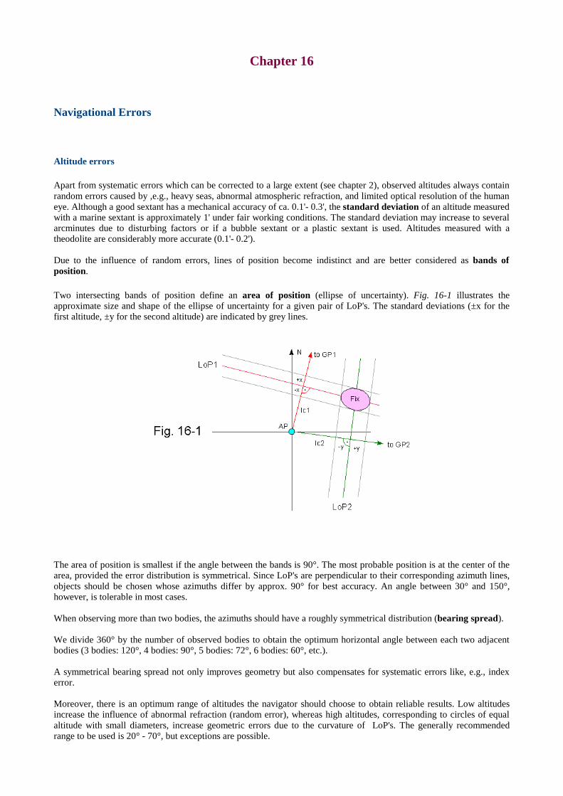
Chapter 16
Navigational Errors
Altitude errors
Apart from systematic errors which can be corrected to a large extent (see chapter 2), observed altitudes always containrandom errors caused by ,e.g., heavy seas, abnormal atmospheric refraction, and limited optical resolution of the humaneye. Although a good sextant has a mechanical accuracy of ca. 0.1'- 0.3', the standard deviation of an altitude measuredwith a marine sextant is approximately 1' under fair working conditions. The standard deviation may increase to severalarcminutes due to disturbing factors or if a bubble sextant or a plastic sextant is used. Altitudes measured with atheodolite are considerably more accurate (0.1'- 0.2').
Due to the influence of random errors, lines of position become indistinct and are better considered as bands ofposition.
Two intersecting bands of position define an area of position (ellipse of uncertainty). Fig. 16-1 illustrates theapproximate size and shape of the ellipse of uncertainty for a given pair of LoP's. The standard deviations (±x for thefirst altitude, ±y for the second altitude) are indicated by grey lines.
The area of position is smallest if the angle between the bands is 90°. The most probable position is at the center of thearea, provided the error distribution is symmetrical. Since LoP's are perpendicular to their corresponding azimuth lines,objects should be chosen whose azimuths differ by approx. 90° for best accuracy. An angle between 30° and 150°,however, is tolerable in most cases.
When observing more than two bodies, the azimuths should have a roughly symmetrical distribution (bearing spread).
We divide 360° by the number of observed bodies to obtain the optimum horizontal angle between each two adjacentbodies (3 bodies: 120°, 4 bodies: 90°, 5 bodies: 72°, 6 bodies: 60°, etc.).
A symmetrical bearing spread not only improves geometry but also compensates for systematic errors like, e.g., indexerror.
Moreover, there is an optimum range of altitudes the navigator should choose to obtain reliable results. Low altitudesincrease the influence of abnormal refraction (random error), whereas high altitudes, corresponding to circles of equalaltitude with small diameters, increase geometric errors due to the curvature of LoP's. The generally recommendedrange to be used is 20° - 70°, but exceptions are possible.
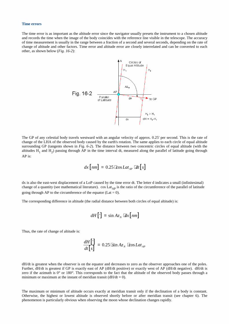
Time errors
The time error is as important as the altitude error since the navigator usually presets the instrument to a chosen altitudeand records the time when the image of the body coincides with the reference line visible in the telescope. The accuracyof time measurement isusually in the range between a fraction of a second and several seconds, depending on the rate ofchange of altitude and other factors. Time error and altitude error are closely interrelated and can be converted to eachother, as shown below (Fig. 16-2):
The GP of any celestial body travels westward with an angular velocity of approx. 0.25' per second. This is the rate ofchange of the LHA of the observed body caused by the earth's rotation. The same applies to each circle of equal altitudesurrounding GP (tangents shown in Fig. 6-2). The distance between two concentric circles of equal altitude (with thealtitudes H1 and H2) passing through AP in the time interval dt, measured along the parallel of latitude going through
AP is:
dx is also the east-west displacement of a LoP caused by the time error dt. The letter d indicates a small (infinitesimal)change of a quantity (see mathematical literature). cos LatAP is the ratio of the circumference of the parallel of latitude
going through AP to the circumference of the equator (Lat = 0).
The corresponding difference in altitude (the radial distance between both circles of equal altitude) is:
Thus, the rate of change of altitude is:
dH/dt is greatest when the observer is on the equator and decreases to zero as the observer approaches one of the poles.Further, dH/dt is greatest if GP is exactly east of AP (dH/dt positive) or exactly west of AP (dH/dt negative). dH/dt iszero if the azimuth is 0° or 180°. This corresponds to the fact that the altitude of the observed body passes through aminimum or maximum at the instant of meridian transit (dH/dt = 0).
The maximum or minimum of altitude occurs exactly at meridian transit only if the declination of a body is constant.Otherwise, the highest or lowest altitude is observed shortly before or after meridian transit (see chapter 6). Thephenomenon is particularly obvious when observing the moon whose declination changes rapidly.
[ ] [ ]sdtLatnmdx AP ⋅⋅= cos25.0
[ ] [ ]nmdxAzdH N ⋅= sin'
[ ][ ] APN LatAzsdt
dHcossin25.0
' ⋅⋅=

A chronometer er ror is a systematic time error. It influences each line of position in such a way that only the longitudeof a fix is affected whereas the latitude remains unchanged, provided the declination does not change significantly(moon!). A chronometer being 1 s fast, for example, displaces a fix 0.25' to the west, a chronometer being 1 s slowdisplaces the fix by the same amount to the east. If we know our position, we can calculate the chronometer error fromthe difference between our true longitude and the longitude found by our observations. If we do not know our longitude,the approximate chronometer error can be found by lunar observations (chapter 7).
Ambiguity
Poor geometry may not only decrease accuracy but may even result in an entirely wrong fix. As the observed horizontalangle (difference in azimuth) between two objects approaches 180°, the distance between the points of intersection ofthe corresponding circles of equal altitude becomes very small (at exactly 180°, both circles are tangent to each other).Circles of equal altitude with small diameters resulting from high altitudes also contribute to a short distance. A smalldistance between both points of intersection, however, increases the risk of ambiguity (Fig. 16-3).
In cases where – due to a horizontal angle near 180° and/or very high altitudes – the distance between both points ofintersection is too small, we can not be sure that the assumed position is always close enough to the actual position.
If AP is close to the actual position, the fix obtained by plotting the LoP's (tangents) will be almost identical with theactual position. The accuracy of the fix decreases as the distance of AP from the actual position becomes greater. Thedistance between fix and actual position increases dramatically as AP approaches the line going through GP1 and GP2(draw the azimuth lines and tangents mentally). In the worst case, a position error of several hundred or even thousandnm may result !
If AP is exactly on the line going through GP1 and GP2, i.e., equidistant from the actual position and the second point ofintersection, the horizontal angle between GP1 and GP2, as viewed from AP, will be 180°. In this case, both LoP's areparallel to each other, and no fix can be found.
As AP approaches the second point of intersection, a fix more or less close to the latter is obtained. Since the actualposition and the second point of intersection are symmetrical with respect to the line going through GP1 and GP2, theintercept method can not detect which of both theoretically possible positions is the right one.
Iterative application of the intercept method can only improve the fix if the initial AP is closer to the actual position thanto the second point of intersection. Otherwise, an "improved" wrong position will be obtained.
Each navigational scenar io should be evaluated cr itically before deciding if a fix is reliable or not. The distancefrom AP to the observer 's actual position has to be considerably smaller than the distance between actualposition and second point of intersection. This is usually the case if the above recommendations regardingaltitude, hor izontal angle, and distance between AP and actual position are observed.

A simple method to improve the reliability of a fix
Each altitude measured with a sextant, theodolite, or any other device contains systematic and random errors whichinfluence the final result (fix). Systematic errors are more or less eliminated by careful calibration of the instrumentused. The influence of random errors decreases if the number of observations is sufficiently large, provided the errordistribution is symmetrical. Under practical conditions, the number of observations is limited, and the error distributionis more or less unsymmetrical, particularly if an outlier, a measurement with an abnormally large error, is present.Therefore, the average result may differ significantly from the true value. When plotting more than two lines of position,the experienced navigator may be able to identify outliers by the shape of the error polygon and remove the associatedLoP's. However, the method of least squares, producing an average value, does not recognize outliers and may yield aninaccurate result.
The following simple method takes advantage of the fact that the median of a number of measurements is much lessinfluenced by outliers than the mean value:
1. We choose a celestial body and measure a series of altitudes. We calculate azimuth and intercept for eachobservation of said body. The number of measurements in the series has to be odd (3, 5, 7...). The reliability of themethod increases with the number of observations.
2. We sort the calculated intercepts by magnitude and choose the median (the central value in the array of interceptsthus obtained) and its associated azimuth. We discard all other observations of the series.
3. We repeat the above procedure with at least one additional body (or with the same body after its azimuth has becomesufficiently different).
4. We plot the lines of position using the azimuth and intercept selected from each series, or use the selected data tocalculate the fix with the method of least squares (chapter 4).
The method has been checked with excellent results on land. At sea, where the observer's position usually changescontinually, the method has to be modified by advancing AP according to the path of travel between the observations ofeach series.
��������
������ �
���� ������ ���������������������������� ����������� ������ ��!�""��������#�$#������"��%��"����"���&���� ����� �� �!� �'(�
�)�� *����!��� �� ���������������� �+������,���� �-��� �.������ �/� �'(������
�0�� �������������� �����(�1���$������2 �-����������!���� ���3����1�))4 �&����� �!5�46760 �'(�
�6�� &����� $�&��� � $ ��#��������� �����# �������5� �������� ���&��"��# -��� ���8��2 �8 �'(��9�� ��1����������2� �������"����' ����1��"�� ���#����������������������:��������;
�<�� &����� $������ ������= &��� �>�������������51������ /���-- ����� (��? @���� �� A�� �>�� ��� �>6��)(> �'B
�C�� $�����B��"" �� ����� ����������� �/�������� ��D�(�������>��$ �$������ �>�����#�9>�����;
�E�� +���B��� ����������F��51"������ ������� ��G�� �����.� �� �(������������������2����� �$���� �>�����#�9>�����;
�7�� B���,.������������������+�����(�� ���� ���������������@������ ��(/,/����� �>�����#�9>�����;
��� +�����!��(��� ���1���2����("�������� �����# �C��5��� �&��������'���� #���� ���EE
��4� ��B�(�������95���; 51"������#(�""��������� ��������������� '���� #(��������2 (�� ��� �&���6�C< �'(�
���� �����5���#�� &��"��(��.�����������9������$�3�)�� �����= �����; )��5��� &������!�������� �&�������� �!��)�C�E �'(�
�������� �
��)�� ����������������9����� �����#�"�������������� �������� ������� ��� ���������; '(>���������������3���� �+� ����� ��&�)464) �'(�
��0�� ��� ��� �*�������������5"������������������� ������ ����F��(�� ������������$#������"�� �>�����#�9>�����;
.�� ���!�#�)6 �)44�
� �� ���� �
�"H%%�������������
�"H%%�����,��������%����%��������%���1���
������ �
���I���������