copper applications fire station lightning protection and ... · pdf file copper applications...
TRANSCRIPT
www.copper.org
CopperApplications
A Case Study
POW
ER Q
UA
LITY
www.copper.org
Fire Station Lightning Protection and Grounding Systems
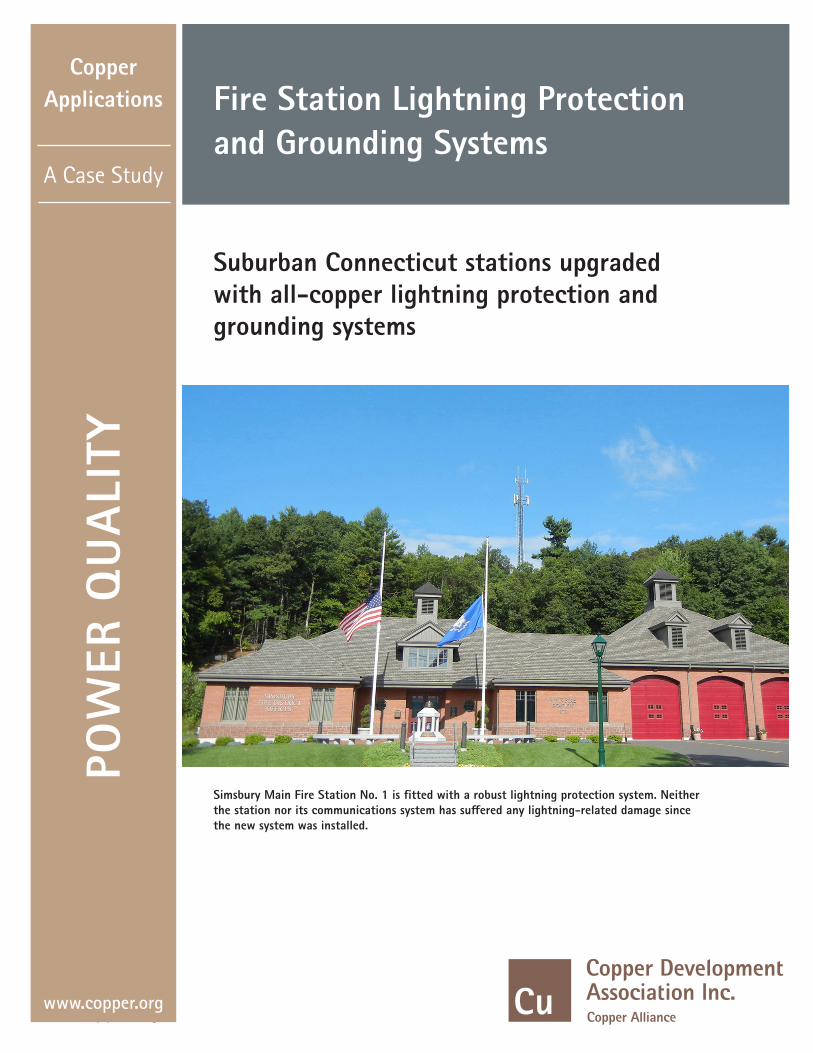
Suburban Connecticut stations upgraded with all-copper lightning protection and grounding systems
Simsbury Main Fire Station No. 1 is fitted with a robust lightning protection system. Neither the station nor its communications system has suffered any lightning-related damage since the new system was installed.

Fire stations fundamentally have only three functions: they’re dormitories for emergency responders, garages for vehicles, and, most importantly, electronic hubs for communications.
Naturally, everything must be up and running 24/7, but reliable communications top the list. Without the ability to communicate, emergency personnel leave property and people at risk. So, given their crucial nature, it stands to reason that communications systems need as much protection that can practically be installed. For most of the country, that means protection from lightning.
This case study describes basic elements of lightning protection systems installed in the headquarters stations of two fire companies serving suburban communities near Hartford, Connecticut.
The stations’ lightning protection and grounding systems were recently upgraded to meet current standards, including the National Fire Protection Association’s NFPA 780: Standard for the Installation of Lightning Protection Systems, Underwriters Laboratories’ UL96A: Installation Requirements for Lightning Protection Systems and the Lightning Protection Institute’s LPI 175: Standard for the Design – Installation – Inspection of Lightning Protection Systems. Standards for hardware and materials are found in UL96: Lightning Protection Components.
That’s quite a few standards for systems that perform what many folks see as a relatively simple task: directing lightning to ground before it can do damage or injure people.
Lightning protection involves more science and technology than otherwise-skilled electricians, electrical contractors, designers and even engineers are aware of. Proper lightning protection is not a do-it-yourself job; it requires trained and certified individuals working with specifically certified materials. “Plus,” adds Mark Morgan, president of East Coast Lightning Equipment, the company that produced and supplied much of the equipment used in the fire stations’ protection systems, “it’s very important that lightning protection gets installed properly because an improper system can do more damage than no system at all.”
The “proper” installer in this case was James G. (Jim) Barnard, a master lightning protection system designer.1 He’s also president of Northeast Lightning Protection, a family-owned business founded in 1976 by Jim’s father. Mr. Barnard’s projects included the lightning protection systems described in this case study, among them the 100% copper system at the main fire station of the Simsbury Fire Protection District shown on the cover and the system at the Wethersfield Fire District located south of the Hartford metro area.
Mr. Barnard was summoned to Simsbury by Kevin Kowalski, Deputy Chief and Chief Administrative Officer of the local Fire Protection District. Chief Kowalski explained: “We’re in the emergency service business, and we need that to be a 100% business. There’s really no answer to a person if there’s a delay in response.
In the old fire station that we had on this property we had a substantial lightning strike that struck our radio system and communications center and knocked us off the air. We wanted to make sure we weren’t going to be put in that situation again. So, when we built a new firehouse in 2010, we decided it would be good value to install a lightning protection system, too.” The chief had lived with the problem and clearly understood it.
Mr. Barnard described the lightning protection system: “We design systems like this based on a 150-ft strike radius. We place air terminals where they’re required by the measurements that radius calls for, in this case every 20 feet. (Figure 1) We connect all air
terminals to each other and to the earth at not less than every 100 ft of the building’s perimeter. Any metallic item we come near to we bond if it falls within a six-ft side flash distance (Figure 2). We also have to bond any underground water or gas pipes where the lightning might follow that path. (Figures 3 and 4, respectively). All these systems must be bonded together.
Figure 3. Braided lightning conductor (29 strands of bare 17-gage copper) is shown bonded to the fire station’s water supply line, left. Note the use of UL96-approved copper alloy mechanical clamps. The clamps resist loosening and corrosion. Similar connections were applied inside the building.
Figure 4. Ground Connection to Gas Service Entrance. The gas service and all exterior metal pipes are connected via the ring ground.
2
Figure 1. Air terminals (strike termination devices) are mounted at a code-mandated maximum 20-ft interval on the roof of the Simsbury Main Station No. 1. The decorative terminal is one of several installed for architectural reasons. Note the braided copper lightning conductors mounted along gable edges.
Figure 2. Rooftop ventilator with air-terminal. The otherwise ungrounded ventilator is within a six-foot strike distance of the lightning protection system’s cabling (not shown) and is therefore connected to it.

www.copper.org
“Outdoors, we also grounded the emergency generator and the generator fuel tank, (Figure 5). Any structural steel members would
also be grounded, as would door tracks if they have a remote path to ground. Downspouts would be grounded if they feed into a metal pipe in the ground.
Figure 5. Grounding connection to the station’s emergency generator shown at left. The braided bare copper grounding cable used here is routed to the generator fuel tank, center, and thence to the station grounding system via a wall penetration visible at right rear.
The chief added, “To facilitate bonding inside rooms we installed halo grounds, or lengths of copper lightning conductor encircling the rooms at near ceiling level. We installed two halos in the fire station: One is in the communications room and one in the server room where everything is terminated.” (Figure 6)
Figure 6. Halo ground installed around interior walls (left) to facilitate connections to electrical, telephone and electronic equipment, cabinet racks and wall penetrations, (right). Note the generous size of the braided lightning cable entering from lower left.
Important Tower GroundsThe station’s communications center is served by a 140-ft tower located uphill and behind the facility (Cover). The tower acts as an ideal lightning rod and readily attracts strikes, as it did during the incident cited by Chief Kowalski. The tower’s lightning protection system includes the tower steel, which is bonded to a buried ring ground and driven electrodes (not shown), the anti-intrusion cyclone fence, and down-conductors from coax cable shields shown connected to a copper grounding bar (Figure 7). The entire tower system is bonded to systems at the fire station and outbuildings, thereby rendering all electrical/electronic equipment at the same ground potential.
Figure 7. Grounding down-conductors from coax cables are bonded to a copper grounding bar near the base of the antenna tower. The tower’s entire grounding system is connected to systems serving the fire station and outbuildings.
Historic Wethersfield System UpgradedJim Barnard and Northeast Lightning Protection also installed a new lightning protection system at Wethersfield’s Fire Station No. 2. The fire district dates to 1803, and the station is one of the oldest in Connecticut. Here Mr. Barnard also worked to a 150-ft strike distance, and air terminal distances are similar to those at Simsbury. Unlike Simsbury’s main station, the Wethersfield facility did not suffer a strike, although the risk was ever-present. According to Mr. Barnard, “We installed the system at the fire station because it’s on a slight rise. Besides, lightning protection doesn’t have to have a history of loss to be a smart idea.”
“Again, what we did here was install direct-strike lightning rods or air terminals on the roof in the places where lightning might strike based on a 150-ft strike radius. (Figure 8) As at Simsbury, the rods are within 24 inches of the outer edge of the roof and 10 inches taller than the objects they’re protecting. Here the lightning rods are tied together by lightning cable containing 29 strands of 17-gage copper wire. The cables have multiple paths to ground situated not more than at 100-ft of perimeter apart on average.
Figure 8. View of the Wethersfield, Connecticut Fire Station No. 2, one of the oldest in the state. The tower behind the station at far left serves the station’s communication needs. Air terminals are spaced at 20-ft increments along the roof ridge line.
“The conductors terminate at four driven electrodes, ½ inch in diameter, extending to 10-ft deep. They are spliced together with buried or above-ground copper splices per UL 96, and anything that’s within distance of 6-ft side-flash distance is also bonded to the grounding system (Figure 9). There are various places where water pipes come into the structure and grounded systems enter the building. At these points, the lightning cable, either by the use of copper water lines or by direct cabling, needs to bond to the sprinkler system, phone grounds, cable TV grounds, and electric grounds. This system is a very effective but simple system of conductors, grounds and bonds.
Figure 9. Left, the braided copper down-conductor is well-concealed, and extends from the rooftop to a driven 10-ft electrode later covered by concrete. The ventilator (Fig. 9, right), being connected to a metal system, is bonded to this down-conductor.
3
www.copper.org
A6171 - XX/15
www.copper.org
This publication has been prepared solely as resource material for the use of individuals involved in the specification, design, selection and installation of electrical systems. It has been compiled from information provided by one or more of the parties mentioned herein and other information sources Copper Development Association Inc. (CDA) and/or the relevant parties believe to be competent. However, recognizing that each system must be designed and installed to meet particular circumstances, CDA and the parties mentioned in this publication assume no responsibility or liability of any kind, including direct or indirect damages in connection with this publication or its use by any person or organization, AND MAKE NO REPRESENTATIONS OR WARRANTIES OF ANY KIND RELATED TO ITS USE, ACCURACY, COMPLETENESS, UTILITY, AVAILABILITY OR DOCUMENTATION.
1 The titles Master Designer and Master Designer/Installer identify individuals certified as such by the Lightning Protection Institute (www.lightning.org), a not-for-profit organization founded in 1955 to promote lightning protection education, awareness and safety.
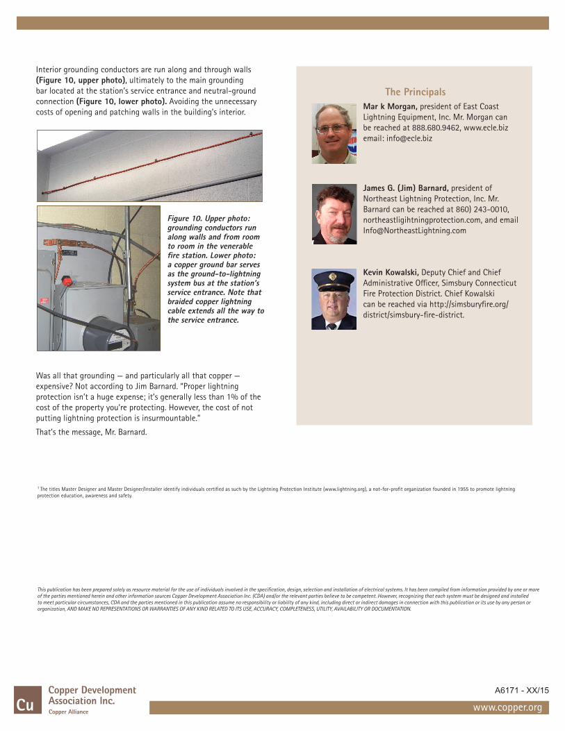
Interior grounding conductors are run along and through walls (Figure 10, upper photo), ultimately to the main grounding bar located at the station’s service entrance and neutral-ground connection (Figure 10, lower photo). Avoiding the unnecessary costs of opening and patching walls in the building’s interior.
Figure 10. Upper photo: grounding conductors run along walls and from room to room in the venerable fire station. Lower photo: a copper ground bar serves as the ground-to-lightning system bus at the station’s service entrance. Note that braided copper lightning cable extends all the way to the service entrance.
Was all that grounding — and particularly all that copper — expensive? Not according to Jim Barnard. “Proper lightning protection isn’t a huge expense; it’s generally less than 1% of the cost of the property you’re protecting. However, the cost of not putting lightning protection is insurmountable.”
That’s the message, Mr. Barnard.
The PrincipalsMar k Morgan, president of East Coast Lightning Equipment, Inc. Mr. Morgan can be reached at 888.680.9462, www.ecle.biz email: [email protected]
James G. (Jim) Barnard, president of Northeast Lightning Protection, Inc. Mr. Barnard can be reached at 860) 243-0010, northeastligihtningprotection.com, and email [email protected]
Kevin Kowalski, Deputy Chief and Chief Administrative Officer, Simsbury Connecticut Fire Protection District. Chief Kowalski can be reached via http://simsburyfire.org/district/simsbury-fire-district.