coordination group for meteorological satellites …...cgms/doc/12/0017 page 1 of 54 cgms lrit/hrit...
TRANSCRIPT

CGMS/DOC/12/0017 Page 1 of 54 CGMS LRIT/HRIT Global Specification Issue 2.8, 30 October 2013 www.cgms-info.org
Coordination Group for
Meteorological Satellites
LRIT/HRIT Global Specification Written by EUMETSAT on behalf of CGMS
CGMS Secretariat c/o EUMETSAT
EUMETSAT Allee 1, 64295 Darmstadt, Germany
www.cgms-info.org [email protected]

CGMS/DOC/12/0017 Page 2 of 54 CGMS LRIT/HRIT Global Specification Issue 2.8, 30 October 2013 www.cgms-info.org
DOCUMENT CHANGE RECORD
Issue Date DCN No. Changed Pages/Paragraphs
2.3 5 July 1993
2.4 21 April 1997 All section/figure renumbering and editorial
changes
sect. 5.4 introduction of data sequencing
2.5 5 October 1998 sect. 1.6.2 rearrangement of reference documents
sect. 2.9 insertion of mission specific compression
methods
sect. 2.10 correction of service compatibility conform
with [RD.5]
sect. 4.2.2.7 insertion of key header record table
sect. 4.3.2 correction of ‘<count>:=’ syntax
sect. 5.3 insertion of mission specific compression
methods
sect. 8.2.1 correction of M_PDU fill mechanism
appendix C amendments in accordance with the above
changes
all minor editorial changes
2.6 9 July 1999 sect. 4.3.3.3 correction of two formulae
sect 7.1 correction of fig. 7-1
2.7 16 October
2012
Sect 4.4.3.1 update reference meridian to refer to IERS
reference meridian (IRM)
Sect 4.4.3.2 update reference parameters to refer to the
World Geodetic System 84 (WGS 84)
2.8 30 October
2013
Sect 4.4.3.2 minor update to precision of reference
parameters

CGMS/DOC/12/0017 Page 3 of 54 CGMS LRIT/HRIT Global Specification Issue 2.8, 30 October 2013 www.cgms-info.org
TABLE OF CONTENTS
Document Change Record .................................................................................................................... 2
Table of Contents ................................................................................................................................... 3
List of Figures ......................................................................................................................................... 6
List of Tables .......................................................................................................................................... 7
1 Introduction ................................................................................................................................. 8 1.1 Purpose of the Mission ........................................................................................................ 8
1.2 Purpose of this Document ................................................................................................... 8
1.3 Scope of this Document....................................................................................................... 8
1.4 Conventions ......................................................................................................................... 8
1.5 LRIT or HRIT ..................................................................................................................... 9
1.6 References ........................................................................................................................... 9
1.6.1 Applicable Documents ........................................................................................... 9
1.6.2 Reference Documents ............................................................................................. 9
2 System Overview ........................................................................................................................ 10 2.1 Communication Model ...................................................................................................... 10
2.2 Application Layer .............................................................................................................. 11
2.3 Presentation Layer ............................................................................................................. 12
2.4 Session Layer .................................................................................................................... 12
2.5 Transport Layer ................................................................................................................. 12
2.6 Network Layer ................................................................................................................... 13
2.7 Data Link Layer ................................................................................................................. 13
2.8 Physical Layer ................................................................................................................... 13
2.9 Applicability of Standards ................................................................................................. 13
2.10 Compatibility with Other Services .................................................................................... 13
3 APPLICATION LAYER .......................................................................................................... 14
4 PRESENTATION LAYER ....................................................................................................... 14 4.1 General .............................................................................................................................. 14
4.2 LRIT/HRIT File Structure ................................................................................................. 14
4.2.1 Top Level File Structure ....................................................................................... 14
4.2.2 Secondary Header Records ................................................................................... 17
4.2.2.1 Image Structure Record ......................................................................... 17
4.2.2.2 Image Navigation Record ..................................................................... 17
4.2.2.3 Image Data Function Record ................................................................ 18
4.2.2.4 Annotation Record ................................................................................ 18
4.2.2.5 Time Stamp Record ............................................................................... 18
4.2.2.6 Ancillary Text Record ........................................................................... 19
4.2.2.7 Key Header Record ............................................................................... 19
4.2.3 Data Field Structure .............................................................................................. 19
4.2.3.1 Image Data Files ................................................................................... 19
4.2.3.2 GTS Message Files ............................................................................... 20
4.2.3.3 Alphanumeric Text Files ....................................................................... 21
4.2.3.4 Encryption Key Message File ............................................................... 21
4.3 Interpretation of Image Data ............................................................................................. 21
4.3.1 Structure of Image Data ........................................................................................ 21
4.3.2 Explicit Image Data Definition ............................................................................. 22
4.3.3 Default Image Data Definition ............................................................................. 23
4.4 Navigation of Image Data ................................................................................................. 24
CGMS/DOC/12/0017 Page 4 of 54 CGMS LRIT/HRIT Global Specification Issue 2.8, 30 October 2013 www.cgms-info.org
4.4.1 General ................................................................................................................. 24
4.4.2 Outline of Navigation Functions .......................................................................... 24
4.4.3 Projection Functions ............................................................................................. 25
4.4.3.1 Geographical Coordinates ..................................................................... 25
4.4.3.2 Normalized Geostationary Projection ................................................... 26
4.4.3.3 Polarstereographic Projection ............................................................... 30
4.4.3.4 Mercator Projection ............................................................................... 31
4.4.4 Scaling Function ................................................................................................... 32
5 Session Layer .............................................................................................................................. 32 5.1 General .............................................................................................................................. 32
5.2 Encryption ......................................................................................................................... 32
5.3 Compression ...................................................................................................................... 32
5.4 Data Sequencing Function ................................................................................................. 33
5.5 Transmission Service Specification .................................................................................. 33
5.5.1 Syntax ................................................................................................................... 33
5.5.2 Function ................................................................................................................ 33
5.6 Reception Service Specification ........................................................................................ 34
5.6.1 Syntax ................................................................................................................... 34
5.6.2 Function ................................................................................................................ 34
6 Transport Layer......................................................................................................................... 34 6.1 General .............................................................................................................................. 34
6.2 Transmission Service Specification .................................................................................. 34
6.2.1 Syntax ................................................................................................................... 34
6.2.2 Function ................................................................................................................ 35
6.3 Reception Service Specification ........................................................................................ 35
6.3.1 Syntax ................................................................................................................... 35
6.3.2 Function ................................................................................................................ 35
6.3.3 Optional Functionality .......................................................................................... 36
7 Network Layer ........................................................................................................................... 36 7.1 General .............................................................................................................................. 36
7.2 Transmission Service Specification .................................................................................. 38
7.2.1 AOS Syntax .......................................................................................................... 38
7.2.2 Function ................................................................................................................ 38
7.3 Reception Service Specification ........................................................................................ 38
7.3.1 AOS Syntax .......................................................................................................... 38
7.3.2 Function ................................................................................................................ 38
8 Data Link Layer ......................................................................................................................... 39 8.1 Overview ........................................................................................................................... 39
8.2 Virtual Channel Link Control Sublayer ............................................................................ 40
8.2.1 General ................................................................................................................. 40
8.2.2 Transmission Service Specification ...................................................................... 41
8.2.2.1 AOS Syntax ........................................................................................... 41
8.2.2.2 Function ................................................................................................ 42
8.2.3 Reception Service Specification ........................................................................... 42
8.2.3.1 AOS Syntax ........................................................................................... 42
8.2.3.2 Function ................................................................................................ 42
8.3 Virtual Channel Access Sublayer ...................................................................................... 43
8.3.1 General ................................................................................................................. 43
8.3.2 Transmission Service Specification ...................................................................... 44
8.3.2.1 AOS Syntax ........................................................................................... 44
8.3.2.2 Function ................................................................................................ 44

CGMS/DOC/12/0017 Page 5 of 54 CGMS LRIT/HRIT Global Specification Issue 2.8, 30 October 2013 www.cgms-info.org
8.3.3 Reception Service Specification ........................................................................... 47
8.3.3.1 AOS Syntax ........................................................................................... 47
8.3.3.2 Function ................................................................................................ 47
8.3.3.3 Optional Functionality .......................................................................... 47
9 Physical Layer ............................................................................................................................ 49
Appendix A - List of Abbreviations.................................................................................................... 50
Appendix B - Data Types .................................................................................................................... 52
Appendix C - List of Mission Specific Items ...................................................................................... 54

CGMS/DOC/12/0017 Page 6 of 54 CGMS LRIT/HRIT Global Specification Issue 2.8, 30 October 2013 www.cgms-info.org
LIST OF FIGURES
FIGURE 2-1 COMMUNICATION MODEL ....................................................................................................... 10 FIGURE 2-2 OVERALL DATA FLOW ............................................................................................................. 11 FIGURE 4-1 LRIT/HRIT FILE STRUCTURE ................................................................................................. 16 FIGURE 4-2 GENERAL LRIT/HRIT HEADER RECORD STRUCTURE ........................................................... 16 FIGURE 4-3 LRIT/HRIT IMAGE STRUCTURE .............................................................................................. 20 FIGURE 4-4 EXAMPLE OF AN IMAGE CONTAINING SEVERAL SUBIMAGES ................................................... 22 FIGURE 4-5 RELATIONSHIP BETWEEN GEOGRAPHICAL AND IMAGE COORDINATES .................................... 24 FIGURE 4-6 GEOGRAPHICAL COORDINATES ............................................................................................... 26 FIGURE 4-7 COORDINATE FRAMES FOR GEOS PROJECTION ...................................................................... 27 FIGURE 4-8 NORMALIZED GEOSTATIONARY PROJECTION .......................................................................... 29 FIGURE 4-9 POLARSTEREOGRAPHIC PROJECTION ....................................................................................... 30 FIGURE 4-10 MERCATOR PROJECTION .......................................................................................................... 31 FIGURE 6-1 TRANSPORT FILE STRUCTURE .................................................................................................. 36 FIGURE 7-1 CP_PDU STRUCTURE .............................................................................................................. 37 FIGURE 8-1 DATA LINK LAYER .................................................................................................................. 39 FIGURE 8-2 M_PDU STRUCTURE ............................................................................................................... 41 FIGURE 8-3 FILL PACKET ............................................................................................................................ 41 FIGURE 8-4 CVCDU STRUCTURE ............................................................................................................... 43 FIGURE 8-5 VCDU PRIMARY HEADER ....................................................................................................... 44 FIGURE 8-6 VCA TRANSMISSION SERVICE ................................................................................................. 46 FIGURE 8-7 VCA RECEPTION SERVICE ....................................................................................................... 48 FIGURE B-1 CHARACTER CODE TABLE ....................................................................................................... 53
CGMS/DOC/12/0017 Page 7 of 54 CGMS LRIT/HRIT Global Specification Issue 2.8, 30 October 2013 www.cgms-info.org
LIST OF TABLES
TABLE 4-1 PRIMARY HEADER RECORD ..................................................................................................... 14 TABLE 4-2 FILE TYPE................................................................................................................................. 15 TABLE 4-3 HEADER RECORD TYPE............................................................................................................ 15 TABLE 4-4 IMAGE STRUCTURE RECORD .................................................................................................... 17 TABLE 4-5 IMAGE NAVIGATION RECORD .................................................................................................. 17 TABLE 4-6 IMAGE DATA FUNCTION RECORD ............................................................................................ 18 TABLE 4-7 ANNOTATION RECORD ............................................................................................................. 18 TABLE 4-8 TIME STAMP RECORD .............................................................................................................. 18 TABLE 4-9 ANCILLARY TEXT RECORD ...................................................................................................... 19 TABLE 4-10 KEY HEADER RECORD ............................................................................................................. 19

CGMS/DOC/12/0017 Page 8 of 54 CGMS LRIT/HRIT Global Specification Issue 2.8, 30 October 2013 www.cgms-info.org
1 INTRODUCTION
1.1 Purpose of the Mission
The intention of LRIT/HRIT is to define a standard for dissemination of data, preferably from
geostationary spacecraft towards LRIT/HRIT user stations.
The main approach of LRIT/HRIT is to disseminate rasterized image data mapped to the surface of
the earth, preferably those generated by or deducted from satellite remote sensing data. Additionally,
LRIT/HRIT shall provide means to forward other types of graphical information, alphanumeric data
or binary data.
The (digital) LRIT mission shall replace the (analogue) WEFAX mission.
LRIT is intended for use on low rate communication links, mainly at 10 kbit/s until 256 kbit/s. HRIT
is intended for use on high rate communication links, mainly at 0.256 Mbit/s through 10 Mbit/s.
1.2 Purpose of this Document
This document provides an architectural specification of the LRIT/HRIT mission from a telecommu-
nications point of view. Thus it does neither define meteorological or other applications nor it
specifies a user station for LRIT/HRIT.
While this document addresses global aspects only, mission specific aspects and implementation
details are specified separately. Both this global specification and the mission specific addendum
make up a complete definition of one LRIT/HRIT implementation.
1.3 Scope of this Document
Since the LRIT/HRIT dissemination mission is understood as a communication between "open
systems", the architecture is conceptually similar to ISO standard 7498 (describing the OSI reference
model). Network and data link layer are specified in conformance with the AOS recommendation,
which is the cleanest and most modern adoption of the OSI model for space communications.
In section 2 an overview of the communication system is provided. Each layer of the communication
model is specified in detail in the subsequent sections. Refer to appendix A for explanations of the
acronyms used in this document.
1.4 Conventions
Within this document the terminology defined in ISO standard 7498 (OSI reference model) is used
assuming the definitions given therein. As an extension, the terminology of CCSDS 701.0 (AOS
architecture) is used for network and data link layers, without repeating the definitions and
explanations given therein, too.
The CCSDS bit numbering convention is adopted for the entire specification herein. Be aware that bit
streams are counted from the MSB onwards, beginning with 0. Groups of eight bits are denoted as
"octets".

CGMS/DOC/12/0017 Page 9 of 54 CGMS LRIT/HRIT Global Specification Issue 2.8, 30 October 2013 www.cgms-info.org
1.5 LRIT or HRIT
The mission shall be named LRIT (Low Rate Image Transmission) if the communication link
provides a data rate below 256 kbit/s. If the data rate is greater than or equal 256 kbit/s then the
mission shall be named HRIT (High Rate Image Transmission).
1.6 References
1.6.1 Applicable Documents
The subsequently listed documents form an integral part of this specification.
[AD.1] CCSDS: "Advanced orbiting systems, networks and data links: architectural specification",
CCSDS recommendation 701.0-B-2, November 1992
[AD.2] ISO: "Information processing systems - open systems interconnection - basic reference
model", ISO standard 7498-1, 1994
[AD.3] ISO: "Information Technology - Digital Compression and Coding of Continuous-tone Still
Images - Requirements and Guidelines, Compliance Testing and Extensions", ISO standards 10918-1,
10918-2, DIS 10918-3
[AD.4] CCSDS: "Time code formats", CCSDS recommendation 301.0-B-2, April 1990
[AD.5] CCSDS: "Telemetry channel coding", CCSDS recommendation 101.0-B-3, May 1992
[AD.6] WMO: "Manual on the GTS", Publication No. 386, Geneva1992
1.6.2 Reference Documents
The subsequently listed documents do not form and integral part of this specification. They are
referenced to provide extended background information.
[RD.1] CCSDS: "Advanced orbiting systems, networks and data links: summary of concept,
rationale and performance", CCSDS report 700.0-G-3, November 1992
[RD.2] not assigned
[RD.3] CCSDS: "Radio frequency and modulation systems, part-1: earth stations and spacecraft",
CCSDS recommendation 401.0-B, Issue 2, November 1994
[RD.4] not assigned
[RD.5] CGMS: CGMS 04 - “Direct Broadcast Services - LRPT/AHRPT Global Specification”,
Issue 1.0

CGMS/DOC/12/0017 Page 10 of 54 CGMS LRIT/HRIT Global Specification Issue 2.8, 30 October 2013 www.cgms-info.org
2 SYSTEM OVERVIEW
2.1 Communication Model
In order to specify the LRIT/HRIT format ISO standard 7498 (OSI reference model) is used as a
basis. LRIT/HRIT is mapped onto seven layers, conceptually similar to the OSI reference model.
Figure 2-1 visualizes how the reference model is applied for LRIT/HRIT.
Due to the fact that LRIT/HRIT is a dissemination mission there is a unidirectional flow of informa-
tion from a transmission system (denoted as TX) to a reception system (denoted as RX). In the
physical representation the transmission system is the central LRIT/HRIT uplink station and the
reception system is one LRIT/HRIT user station.
There are seven layers specified for the communication process, with increasing level of abstraction,
beginning with the physical layer at the bottom of the stack, ending up with the application layer at its
top. Below the communication system there is the communications media, which is the space path
from the uplink station towards the user station including the transponder functionality of the
spacecraft.
For each of the communications layers a service data unit (SDU) can be defined, which is the data
structure appearing at the top of that layer. Additionally, for each layer there is a set of services to be
named. In this special application, the TX services for one layer receive the related SDU as input, and
the RX services generate the related SDU as output.
LRIT/HRIT provides means for packetized communication. Several application processes on the TX
side may send data, virtually parallel, to their partners on the RX side. Each application process is
identified by its application process identifier (APID). Figure 2-2 shows the situation. For
LRIT/HRIT, layers 1...6 are specified.
In the subsequent sections (2.2 - 2.8) there is an outline of the communication layers. In sections 3
through 9 each communication layer is specified in detail then.
Figure 2-1 Communication Model

CGMS/DOC/12/0017 Page 11 of 54 CGMS LRIT/HRIT Global Specification Issue 2.8, 30 October 2013 www.cgms-info.org
Figure 2-2 Overall Data Flow
2.2 Application Layer
The application layer describes the information interchange between application entities.
Examples for application entities on the TX side could be
- a process generating image products from remote sensing data
- a spacecraft operator issuing an administrative message
- a process generating meteorological bulletins.
On the RX side one could find possible application entities in
- a process visualizing image loops
- a user station operator reading an administrative message
- an application program processing meteorological bulletins.
There is no service data unit for the application layer.

CGMS/DOC/12/0017 Page 12 of 54 CGMS LRIT/HRIT Global Specification Issue 2.8, 30 October 2013 www.cgms-info.org
2.3 Presentation Layer
The service data unit for the presentation layer is the user data (e.g. image product, administrative
message, meteorological bulletin), which it is receiving from or sending to the application layer.
Within the presentation layer the information is transformed from a form suitable for presentation (i.e.
user data) to a form suitable for issuing a communications session (i.e. a file containing LRIT/HRIT
data) or vice versa.
Consequently, from the presentation layer point of view, the underlying communication is a transfer
of LRIT/HRIT files from the transmission system to the reception system, each of them represented
by its session layer.
Within the presentation layer the detailed structure of LRIT/HRIT files is specified, but neither the
possible usage of the data therein (this belongs to the application layer) nor the method of sending it
from the TX presentation layer towards the RX presentation layer (this belongs to the session layer).
2.4 Session Layer
The session layer describes how an LRIT/HRIT file (the session SDU) is send from the TX system to
the RX system, without uncovering the transport mechanism. For LRIT/HRIT dissemination, there are
two pairs of complementary services to be performed:
- compression and decompression of data, if required
- encryption and decryption of data, if required
In addition a mission specific data sequencing on ‘LRIT/HRIT file level’ could be applied as an
alternative to the priority scheme used in the transport layer to cope with stringent data specific
timeliness requirements.
From the session layer point of view, the underlying communication can be described as the
transportation of an LRIT/HRIT file (prepared for shipping) from TX transport layer to RX transport
layer.
2.5 Transport Layer
The transport layer provides means for transferring a file through the packet multiplexing network.
On the TX side a suitable packet channel is selected and the file is partitioned into one or more
segments, each of them packed into a CCSDS conforming source data packet.
On the RX side the file segments are retrieved from incoming packets and the segments are
reassembled to LRIT/HRIT files.
Thus, the transport layer does not know anything about structure and contents of the LRIT/HRIT files
it is transporting nor it is involved in how source packets are forwarded from the TX system to the RX
system.

CGMS/DOC/12/0017 Page 13 of 54 CGMS LRIT/HRIT Global Specification Issue 2.8, 30 October 2013 www.cgms-info.org
2.6 Network Layer
The network layer is responsible for controlling the path on which a source is transferred through the
communication system. For LRIT/HRIT, the only activity required is to select the path (i.e. the virtual
channel) upon transmitting a source packet, and to forward it to the transport layer of its addressed
application upon reception.
2.7 Data Link Layer
The data link layer performs the transfer of a CCSDS source packet on a predefined path through the
data link.
The underlying communication system is capable of forwarding a serial bitstream from the
transmission system to the reception system, both represented by its physical layers.
While multiple communication tasks may run on the higher layers simultaneously, the underlying
physical layer is capable of transferring a single bitstream only. Consequently, incoming source
packets must be multiplexed on the transmitting side and demultiplexed on the receiving side. Below
packet multiplexing, the virtual channel data units (VCDUs) must be commutated onto the physical
link and decommutated at the receiving side. Last, the VCDU stream must be serialized on the TX
side and the VCDUs must be acquired from the serial bitstream on the RX side.
2.8 Physical Layer
The physical layer performs the transfer of the serial bitstream from the TX system to the RX
systems. For this purpose, the bitstream must be modulated onto a transmission carrier signal and
demodulated on the receiving side. The modulated signal must be transmitted through the
communications media and received from that on the receiving side.
2.9 Applicability of Standards
LRIT/HRIT should be understood as an open system by design, conceptually similar to OSI reference
model defined in ISO 7498 [AD.2].
Network layer and data link layer are specified according to CCSDS recommendation 701 for
advanced orbiting systems [AD.1].
Related to that, the applied FEC mechanism (on data link layer) conforms with CCSDS
recommendation 101 [AD.5]. The use of FEC (e.g. convolutional coding) in the physical layer and its
concatenation with the data link layer FEC (Reed-Solomon coding) is mission specific.
As far as time codes are used in the data structures, they are defined in accordance with CCSDS
recommendation 301 [AD.4].
Compression of image data is either performed in accordance with the "JPEG" standard [AD.3] or in
accordance with any other compression algorithm identified via a mission specific header.
2.10 Compatibility with Other Services
It is intended to specify LRIT as compatible as possible with LRPT [RD.5], which is the related
"secondary" dissemination service from polar orbiting satellites. For this reason, the data link and
network layers of both protocols are compatible as far as it concerns the RX side.
CGMS/DOC/12/0017 Page 14 of 54 CGMS LRIT/HRIT Global Specification Issue 2.8, 30 October 2013 www.cgms-info.org
3 APPLICATION LAYER
The application layer is the window between the application process and the communication system.
For LRIT/HRIT we have to outline possible applications of the data forwarded through the
communication system.
There are no global specifications related to the application layer.
4 PRESENTATION LAYER
4.1 General
The presentation layer provides means for representation of information. The structure of data sets is
defined herein together with all codes used therein. For image data services are provided for
navigation and for retrieving their physical interpretation.
The presentation layer is completely defined by specifying syntax and semantics of LRIT/HRIT files.
Section 4.2 provides a general definition, while section 0 (interpretation of image data) and section
4.4 (navigation of image data) address complex aspects related to image files only.
4.2 LRIT/HRIT File Structure
4.2.1 Top Level File Structure
An LRIT/HRIT file consists of one or more header records and one data field (see Figure 4-1).
In the header records information describing the contents of the data field is provided.
Each header record has the structure outlined in Figure 4-2. Up to 256 types of header records can be
defined. Some of them may occur several times with one file. The first header record (which is the
only one being mandatory) must be of type 0 identifying it as the so-called primary header record.
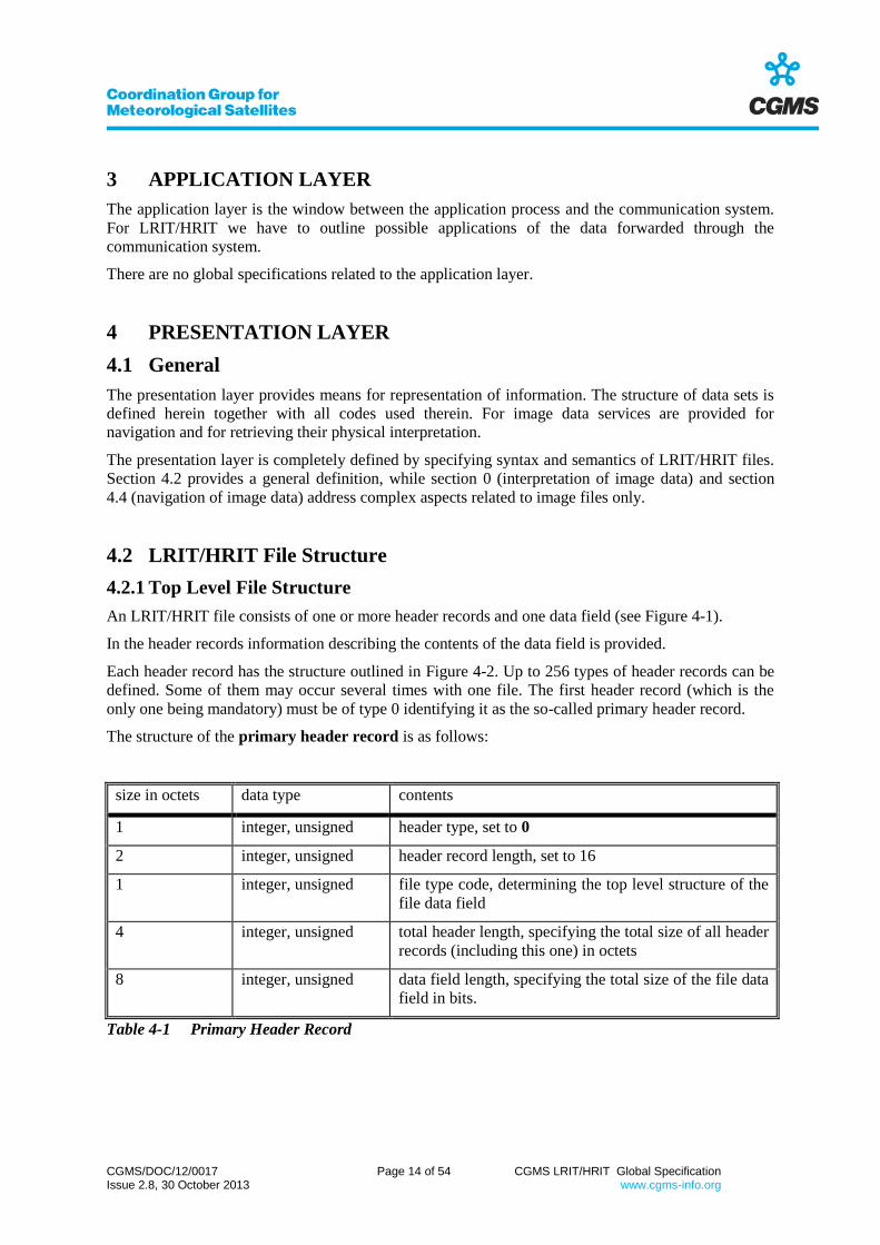
The structure of the primary header record is as follows:
size in octets data type contents
1 integer, unsigned header type, set to 0
2 integer, unsigned header record length, set to 16
1 integer, unsigned file type code, determining the top level structure of the
file data field
4 integer, unsigned total header length, specifying the total size of all header
records (including this one) in octets
8 integer, unsigned data field length, specifying the total size of the file data
field in bits.
Table 4-1 Primary Header Record

CGMS/DOC/12/0017 Page 15 of 54 CGMS LRIT/HRIT Global Specification Issue 2.8, 30 October 2013 www.cgms-info.org
The following file types are supported:
code file type
0 image data file
1 GTS message
2 alphanumeric text file
3 encryption key message
4...127 reserved for future global usage
128...255 for mission specific use
Table 4-2 File Type
The following header record types are supported:
code header record type mandatory for file type optional for file type
0 primary header all -
1 image structure 0 -
2 image navigation - 0
3 image data function - 0
4 annotation - all
5 time stamp - all
6 ancillary text - all
7 key header - all
8...127 reserved for future global
usage
128...255 for mission specific use
Table 4-3 Header Record Type

CGMS/DOC/12/0017 Page 16 of 54 CGMS LRIT/HRIT Global Specification Issue 2.8, 30 October 2013 www.cgms-info.org
first header record
n-th header record
data field
optional
Figure 4-1 LRIT/HRIT File Structure
type length data
n (structure depends on type)
1 octet 2 octets n-3 octets
4 ... 65535 octets
Figure 4-2 General LRIT/HRIT Header Record Structure

CGMS/DOC/12/0017 Page 17 of 54 CGMS LRIT/HRIT Global Specification Issue 2.8, 30 October 2013 www.cgms-info.org
4.2.2 Secondary Header Records
4.2.2.1 Image Structure Record
This record determines the structure of an image. It is mandatory for image data files and applicable
to image data files only. The structure is as follows:
size in octets data type contents abbreviation
1 integer, unsigned header type, set to 1
2 integer, unsigned header record length, set to 9
1 integer, unsigned number of bits per pixel (1 ... 255) NB
2 integer, unsigned number of columns (1 ... 65535) NC
2 integer, unsigned number of lines (1 ... 65535) NL
1 integer, unsigned compression flag (0,1,2) CFLG
Table 4-4 Image Structure Record
Refer to section 4.2.3.1 for details on image data.
4.2.2.2 Image Navigation Record
This record determines the mapping of the image onto the earth. It is applicable to image data files
only. The structure is as follows:
size in octets data type contents abbreviation
1 integer, unsigned header type, set to 2
2 integer, unsigned header record length, set to 51
32 character projection name
4 integer, signed column scaling factor CFAC
4 integer, signed line scaling factor LFAC
4 integer, signed column offset COFF
4 integer, signed line offset LOFF
Table 4-5 Image Navigation Record
Refer to section 4.4 for details on image navigation.

CGMS/DOC/12/0017 Page 18 of 54 CGMS LRIT/HRIT Global Specification Issue 2.8, 30 October 2013 www.cgms-info.org
4.2.2.3 Image Data Function Record
This record determines the physical meaning of the image data. The structure is as follows:
size in octets data type contents
1 integer, unsigned header type, set to 3
2 integer, unsigned header record length
up to 65532 character data definition block
Table 4-6 Image Data Function Record
Refer to section 0 for details about the data definition block.
4.2.2.4 Annotation Record
This record is used to specify an alphanumeric annotation for the file. It is optional for all file types.
The structure is as follows:
size in octets data type contents
1 integer, unsigned header type, set to 4
2 integer, unsigned header record length
up to 64 character annotation text
Table 4-7 Annotation Record
4.2.2.5 Time Stamp Record
This record is used to apply a time stamp to the file. It is optional for all file types. The structure is as
follows:
size in octets data type contents
1 integer, unsigned header type, set to 5
2 integer, unsigned header record length, set to 10
7 CCSDS time time stamp
Table 4-8 Time Stamp Record

CGMS/DOC/12/0017 Page 19 of 54 CGMS LRIT/HRIT Global Specification Issue 2.8, 30 October 2013 www.cgms-info.org
4.2.2.6 Ancillary Text Record
This record is used to attach ancillary text information to the file. It is optional for all file types. The
structure is as follows:
size in octets data type contents
1 integer, unsigned header type, set to 6
2 integer, unsigned header record length
up to 65532 character ancillary text
Table 4-9 Ancillary Text Record
4.2.2.7 Key Header Record
This record is used to control encryption of the file. It has no meaning within the presentation layer.
Any such header record, identified by header type 7, shall be ignored by the presentation layer.
size in octets data type contents
1 integer, unsigned header type, set to 7
2 integer, unsigned header record length
up to 65532 character key header information (mission specific)
Table 4-10 Key Header Record
4.2.3 Data Field Structure
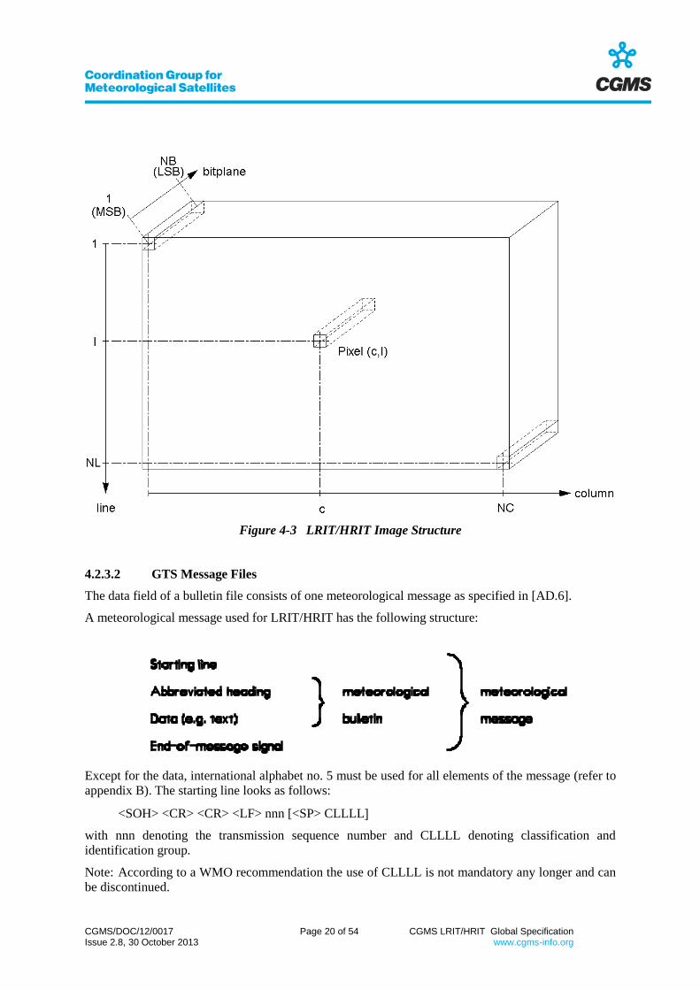
4.2.3.1 Image Data Files
The data field of image data files consists of a sequence of pixels, without any gaps in between. The
size of one pixel (in bits) is specified in the image structure record (sect. 4.2.2.1) as well as the
number of columns (denoted as NC in the following) and the number of lines (NL herein). The pixels
appear with the MSB first. The total number of pixels is NC·NL, thus the total data field size is
NC·NL times the pixel size. The pixels are sorted line-by-line, from left to right and from top to
bottom. Accordingly, column numbers are counted from 1 to NC, and line numbers from 1 to NL.
Consequently, the first pixel in the data field (the left uppermost one) has the coordinates (1,1) and the
last pixel (the bottom right one) has the coordinates (NC, NL). Figure 4-3 shows the structure of an
LRIT/HRIT image.
The compression flag in the image structure record has no direct effect on the presentation of image
data, however the following shall be noted:
The usage of compression (CFLG = 1 or 2) may cause restriction on the permitted values for
NB.
If a lossy compression method is used (CFLG = 2), users shall be aware of the non-perfect
reconstruction of data. From the users point of view there is no difference whether transmission
is performed without compression (CFLG = 0) or with lossless compression (CFLG = 1).
CGMS/DOC/12/0017 Page 20 of 54 CGMS LRIT/HRIT Global Specification Issue 2.8, 30 October 2013 www.cgms-info.org
Figure 4-3 LRIT/HRIT Image Structure
4.2.3.2 GTS Message Files
The data field of a bulletin file consists of one meteorological message as specified in [AD.6].
A meteorological message used for LRIT/HRIT has the following structure:
Except for the data, international alphabet no. 5 must be used for all elements of the message (refer to
appendix B). The starting line looks as follows:
<SOH> <CR> <CR> <LF> nnn [<SP> CLLLL
with nnn denoting the transmission sequence number and CLLLL denoting classification and
identification group.
Note: According to a WMO recommendation the use of CLLLL is not mandatory any longer and can
be discontinued.

CGMS/DOC/12/0017 Page 21 of 54 CGMS LRIT/HRIT Global Specification Issue 2.8, 30 October 2013 www.cgms-info.org
The abbreviated heading has the following structure:
<CR> <CR> <LF> TTAAii <SP> CCCC <SP> YYGGgg [<SP> BBB]
with TTAAii denoting the data designators, CCCC being the station indicator and YYGGgg
containing the international date-time group. The optional BBB indicator is used to avoid multiply
occuring abbreviated headings.
The end-of-message signal is defined as follows:
<CR> <CR> <LF> <ETX>
For details on meteorological messages the reader shall refer to [AD.6].
4.2.3.3 Alphanumeric Text Files
The data field consists of a sequence of ASCII coded characters, using one octet per character.
Consecutive lines of text shall be separated by <CR><LF>. Refer to appendix B for definition of the
code.
4.2.3.4 Encryption Key Message File
These files are used for distribution of key information within an encryption infrastructure. The data
field structure is mission specific.
4.3 Interpretation of Image Data
4.3.1 Structure of Image Data
One image consists of a matrix of pixels, each of them having the same structure. The matrix size is
defined by NC and NL in the image structure record (refer to section 4.2.2.1), the size of one pixel is
defined by NB.
The bits of one pixel are oriented from MSB through LSB, counted from 1 to NB. The matrix made
up by selecting one specific bit from every pixel is called bitplane. One image consists of NB
bitplanes.
One image consists of one or more subimages, each of them made up by a group of one or more
consecutive bitplanes. One subimage refers to one set of information (e.g. radiometer channel, graphic
overlay etc.). Figure 4-4 shows a configuration of several subimages.
In analogy, one pixel consists of one or more subpixels. The default value of one subpixel is
determined by the binary representation of its bits (called subpixel count), thus inbetween 0 and 2n-1
(where n denotes the number of bitplanes belonging to the subimage). Other values may be assigned
to a subpixel by means of suitable equivalence statements in the data definition block contained in the
(optional) image data function record (refer to section 4.2.2.3).
Note that all subimages are transmitted in parallel. Refer to section 4.2.3.1 on how the image data is
presented.

CGMS/DOC/12/0017 Page 22 of 54 CGMS LRIT/HRIT Global Specification Issue 2.8, 30 October 2013 www.cgms-info.org
Figure 4-4 Example of an Image containing several Subimages
4.3.2 Explicit Image Data Definition
In order to specify the data of one image file, a data definition block may be submitted with an
(optional) image data function record (refer to section 4.2.2.3).
The data definition block consists of one or more statements, separated by the delimiter <CR>. Within
the statement, zero or more <SP>, <HT>, <LF> characters may be inserted anywhere.
The meaning of one subimage can be defined with one type statement:
<type> := <number of bitplanes>
All bitplanes must be defined, the first type statement defines the most significant bit(s), the last
statement defines the least significant bit(s). The following values are supported for <type>:
$HALFTONE
Specifies a halftone greyscale, i.e. the subpixel counts are related to quantized samples of a
continuous physical value (such as "intensity" or "temperature").
$DISCRETE
Specifies a discrete greyscale, i.e. each subpixel count has a unique meaning (such as "snow",
"rain", "water", "land", or "cloud").
$OVERLAY

CGMS/DOC/12/0017 Page 23 of 54 CGMS LRIT/HRIT Global Specification Issue 2.8, 30 October 2013 www.cgms-info.org
Specifies a discrete overlay. All zero represents the overlay to be off. All other subpixel counts
represent overlay conditions.
The variable <number of bitplanes> may be set to any decimal integer between 1 and NB (refer to
section 4.2.2.1). Not more than 3 digits must be provided. The sum of all <number of bitplanes> in all
type statements must be equal to the number of bits per pixel (i.e. NB). The value 1 is not permitted
for $HALFTONE.
After each type statement zero or more non-type statements may appear, providing more definitions
related to the subimage specified by the preceding type statement. The following statements are
supported:
_NAME:=<name>
Specifies a name for the subimage, such as "Infrared" or "Normalized Vegetation Index" or
"Cloud classification". <name> denotes a character string not longer than 64 characters. The usage of
this statement is optional for all types. It must not occur more than once with one type statement.
_UNIT:=<unit>
Specifies a physical unit to be used with the subimage such as "Degree Celsius". This statement
is supported for $HALFTONE and $DISCRETE types only. It is optional. It must not occur more
than once with one type statement.
<count>:=<numeric value>
establishes a relationship between a numeric value and one subpixel count. The variable
<count> may be set to any decimal integer between 0 and 2n-1 where n represents the number of
bitplanes in the preceding type statement. The numeric value can be any integer or real, consisting of
a "+" or "-" sign, decimal digits and a decimal point. Sign and decimal point have to be specified if
needed only. The entire string describing the numeric value must not exceed 64 characters in length.
The usage of this statement is optional for all types. Equivalencing a subset of all possible counts is
permitted. In case of $HALFTONE type, linear interpolation is assumed for bridging definition gaps.
<count>:=<alphanumeric value>
establishes a relationship between an alphanumeric meaning and a subpixel count. The variable
may be set to any decimal integer between 0 and 2n-1 where n represents the number of bitplanes in
the preceding type statement. The alphanumeric value can be any character string not longer than 64
characters. The usage of this statement is optional for all types.
Note that each <count> value can only be used once for one subimage data definition.
4.3.3 Default Image Data Definition
If no image data function record is provided with the image file then the following is assumed: The
image consists of one subimage. The data function type is $HALFTONE, except for NB=1 where
$DISCRETE is assumed. No data name, no unit name and no value equivalences are specified.

CGMS/DOC/12/0017 Page 24 of 54 CGMS LRIT/HRIT Global Specification Issue 2.8, 30 October 2013 www.cgms-info.org
4.4 Navigation of Image Data
4.4.1 General
Each pixel of an LRIT/HRIT image is addressed by a pair of coordinates: the column number c and
the line number l. Refer to Figure 4-3 for details.
Optionally, by means of an image navigation record (refer to section 4.2.2.2), the line-column raster
can be mapped to geographical coordinates and vice versa.
In the following this relation is defined.
4.4.2 Outline of Navigation Functions
The relation between image coordinates and geographical coordinates is determined by the
concatenation of two functions in each direction:
Figure 4-5 Relationship between geographical and image coordinates
Note that the geographical coordinates (lon and lat) and the intermediate coordinates (x and y) are real
numbers while the image coordinates (l and c) are integer numbers.
CGMS/DOC/12/0017 Page 25 of 54 CGMS LRIT/HRIT Global Specification Issue 2.8, 30 October 2013 www.cgms-info.org
The projection functions
x
y
lon
latf
and
lon
lat
x
yf
1
are nonlinear functions specified by the projection name. Refer to section 4.4.3 for details on global
definitions. More projection functions may be specified for the actual implementation (i.e. mission
specific).
The scaling functions
c
l
x
yg
and
x
y
c
lg
1
are linear functions specified by the scaling factors CFAC and LFAC and by the offsets COFF and
LOFF. Refer to section 4.4.4 for details.
4.4.3 Projection Functions
4.4.3.1 Geographical Coordinates
For LRIT/HRIT, one location on earth is determined by its longitude (lon) and its geographical
latitude (lat). Both coordinates are specified in degree.
The longitude is counted eastwards positive, beginning at the IERS Reference Meridian. The
permitted range is -180.0 ... +180.0. The latitude is counted from -90.0 (south pole) through 0.0
(equator) until +90.0 (north pole).
Figure 4-6 shows the situation for a spherical model of the earth. Note that when using an ellipsoid as
a model of the earth, geographical and geocentric latitude will be different.

CGMS/DOC/12/0017 Page 26 of 54 CGMS LRIT/HRIT Global Specification Issue 2.8, 30 October 2013 www.cgms-info.org
Figure 4-6 Geographical Coordinates
4.4.3.2 Normalized Geostationary Projection
The projection name string shall be specified as
GEOS (<sub_lon>)
where <sub_lon> specifies the subsatellite longitude in degree, as an integer or real decimal string.
The World Geodetic System 1984 (WGS84) is used to define the values of the elements used in the
projection.
The normalized geostationary projection describes the view from a virtual satellite to an idealized
earth. Herein, the virtual satellite is in a geostationary orbit, perfectly located in the equator plane
exactly at longitude sub_lon. The distance between spacecraft and centre of earth is 42164 km. The
idealized earth is a perfect ellipsoid with an equator radius of 6378.1370 km and a polar radius of
6356.7523 km.
In the following a short description of the theoretical background is provided:
Two Cartesian coordinate frames are introduced.(e1,e2,e3) has its origin in the centre of the earth. (e3)
points in northern direction, (e1) points towards the Greenwich meridian. (s1,s2,s3) has its origin at the
satellite position. Again (s3) points northwards, and (s1) directs to the centre of the earth. Figure 4-7
visualizes this situation and identifies several angles and lengths used in the following.
The earth is described as an oblate rotational ellipsoid.
IERS Reference Meridian

CGMS/DOC/12/0017 Page 27 of 54 CGMS LRIT/HRIT Global Specification Issue 2.8, 30 October 2013 www.cgms-info.org
km 06378.1 =
km 6356. =
1 = +
r
r
r
ee
r
e
eq
pol
eqpol
37
7523
2
2
2
2
1
2
2
3
The vector re points from the centre of the earth to a point P on the earth's surface. Thus, λe is the
longitude and e is the geocentric latitude describing the point P. The transformation from geographic
coordinates (lon, lat) is as follows:
lat=
lon
r
r
eq
pol
e
e
tanarctan2
2
Figure 4-7 Coordinate Frames for GEOS Projection
The length of re is:
e
pol
eq2
pol2
eq2
2
e
r = r
1-r - r
r( )cos
CGMS/DOC/12/0017 Page 28 of 54 CGMS LRIT/HRIT Global Specification Issue 2.8, 30 October 2013 www.cgms-info.org
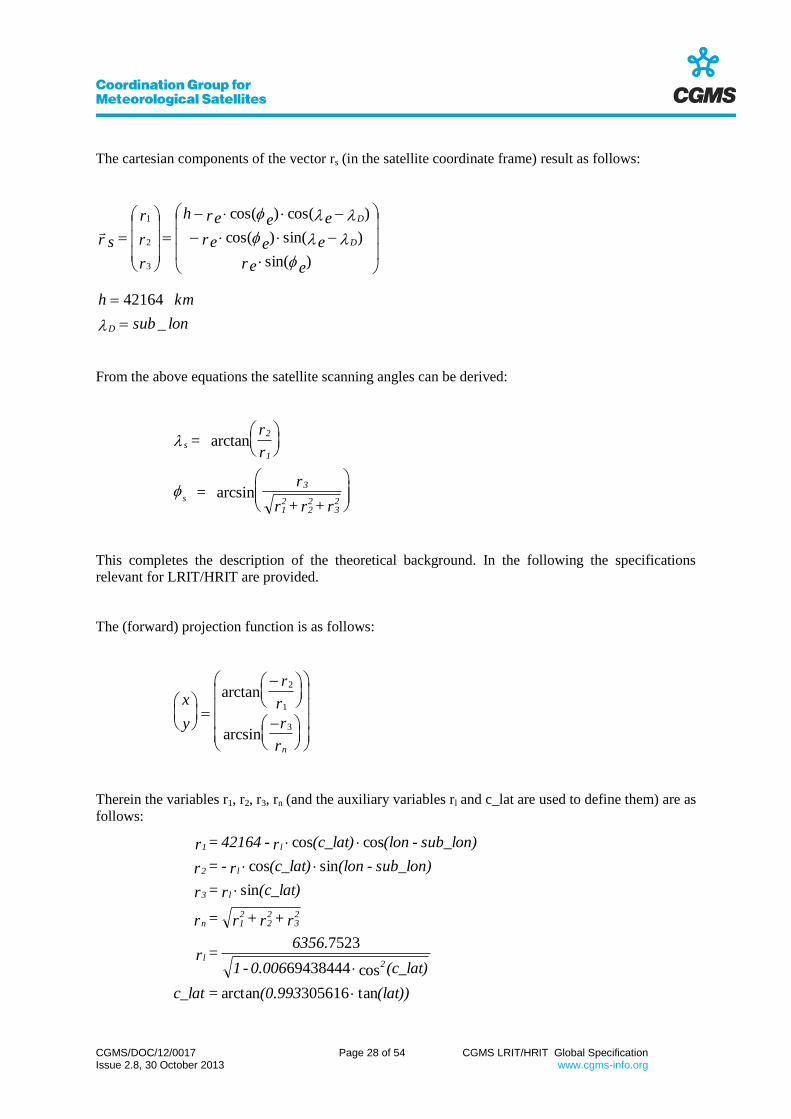
The cartesian components of the vector rs (in the satellite coordinate frame) result as follows:
lonsub
kmh
ere
eere
eereh
r
r
r
r s
D
D
D
_
42164
)sin(
)sin()cos(
)cos()cos(
3
2
1
From the above equations the satellite scanning angles can be derived:
s
2
1
s
3
12
22
32
= r
r
= r
r + r + r
arctan
arcsin
This completes the description of the theoretical background. In the following the specifications
relevant for LRIT/HRIT are provided.
The (forward) projection function is as follows:
x
y
r
r
r
rn
arctan
arcsin
2
1
3
Therein the variables r1, r2, r3, rn (and the auxiliary variables rl and c_lat are used to define them) are as
follows:
(lat))(0.993 = c_lat
(c_lat) 0.006 - 1
6356. = r
r + r + r = r
(c_lat) r = r
sub_lon)- (lon (c_lat) r- = r
sub_lon)- (lon (c_lat) r - 42164 = r
2l
23
22
21n
l3
l2
l1
tan305616arctan
cos69438444
7523
sin
sincos
coscos

CGMS/DOC/12/0017 Page 29 of 54 CGMS LRIT/HRIT Global Specification Issue 2.8, 30 October 2013 www.cgms-info.org
The inverse projection function is as follows:
ss
ss
xy
lonsub
lat
lon
3
1
2
006739501.1arctan
_arctan
Therein the variables s1, s2, s3, sxy (and the auxiliary variables sn and sd used to define them) are as
follows:
2264sin739501coscoscos
sin739501cos
coscos
sin
cossin
coscos
173712 (y)) 1.006 + (y)( - )(y) (x) (42164 = s
(y) 1.006 + (y)
s - (y) (x) 42164 = s
s + s = s
(y) s- = s
(y) (x) s = s
(y) (x) s - 42164 = s
222
d
22
dn
22
21xy
n3
n2
n1
Note that all trigonometric functions shall assume angles in degree, even for x and y.
Figure 4-8 shows a grid of geographical coordinates in normalized geostationary projection.
Figure 4-8 Normalized Geostationary Projection

CGMS/DOC/12/0017 Page 30 of 54 CGMS LRIT/HRIT Global Specification Issue 2.8, 30 October 2013 www.cgms-info.org
4.4.3.3 Polarstereographic Projection
The projection name string shall be specified as
POLAR(<prj_dir>,<prj_lon>)
where <prj_dir> specifies the projection plane and <prj_lon> the central longitude.
<prj_dir> can be either N or S denoting north polar stereographic projection (i.e. the north pole is the
centre of the projection plane) or south polar stereographic projection (i.e. the south pole is the centre
of the projection plane).
<prj_lon> can be any integer or real between -180 and +180, specifying the central longitude in
degree.
The projection functions are as follows:
With help of the auxiliary parameter
d := +1 if prj_ dir = N
- 1 else (if prj_ dir = S)
the (forward) projection function is
prj_lon) - (lon
prj_lon - (lonlatd =
y
x
cos
)sin
2
90tan
and thus its inversion is
)y2
+ x2(2 - 90
y
x
d
sgn(y))- (190d + prj_lon +
= lat
lon
arctan
arctan
Polarstereographic projection is based on a spherical model of the earth.
Figure 4-9 shows a grid of geographical coordinates in polarstereographic projection.
Figure 4-9 Polarstereographic Projection

CGMS/DOC/12/0017 Page 31 of 54 CGMS LRIT/HRIT Global Specification Issue 2.8, 30 October 2013 www.cgms-info.org
4.4.3.4 Mercator Projection
The projection name shall be
MERCATOR
without any further parameter.
The projection functions are as follows:
x
y
lon
lat
x
e
lon
lat
y
180
1 902
180
90 2
ln tan
arctan
Mercator projection is based on a spherical model of the earth.
Figure 4-10 shows a grid of geographical coordinates in Mercator projection.
Figure 4-10 Mercator Projection

CGMS/DOC/12/0017 Page 32 of 54 CGMS LRIT/HRIT Global Specification Issue 2.8, 30 October 2013 www.cgms-info.org
4.4.4 Scaling Function
The scaling function provides a linear relation between the intermediate coordinates (x,y) and the
image coordinates (c,l).
The definition is as follows:
c = COFF + nint(x 2 CFAC)
l = LOFF + nint(y 2 LFAC)
-16
-16
Herein, "nint" denotes a nearest integer rounding of the real argument. COFF, CFAC, LOFF, LFAC
are the (integer) scaling coefficients provided with the image navigation record. Each of the
coefficients may have an integer value between -231
and +231
-1.
For the common orientation of the image both CFAC shall be positive. In order to support near real-
time transmission of image data scanned from south to north LFAC may be selected negative.
5 SESSION LAYER
5.1 General
The session layer provides a means for interchange of data useable for presentation. Main approach of
the session layer for LRIT/HRIT is to perform compression and encryption of data, and the
complementary transformations.
The session layer interfaces to the transport layer and to the presentation layer. Both service data unit
and protocol data unit is one LRIT/HRIT file as defined in section 4.2. Consequently session services
modify LRIT/HRIT files.
Contents and length of the data field may be changed upon session layer processing. Header records
must not be affected by RX processing (i.e. decryption and decompression). If stringent timeliness
requirements on file level shall be applied rather than making use of the priority scheme specified as
part of the transport layer, the TX processing can optionally include a data sequencing function.
5.2 Encryption
All types of LRIT/HRIT files can be encrypted. The encryption method and the key distribution
scheme are mission specific. However, the following global baseline shall be kept:
- Information required by authorised users for decrypting a file (e.g. key number) shall be
included in a key header record, identified by header type 7.
- In case of key distribution via the mission LRIT/HRIT file type 3 (encryption key message)
shall be used for this purpose.
5.3 Compression
Compression may be applied to LRIT/HRIT image data files (file type 0) only.
The compression flag in the image structure record (refer to section 4.2.2.1) determines whether the
file's data field contains "clear" image data or a compressed data format: If the compression flag is
nonzero then compression is selected.

CGMS/DOC/12/0017 Page 33 of 54 CGMS LRIT/HRIT Global Specification Issue 2.8, 30 October 2013 www.cgms-info.org
Upon compression, the data field of the LRIT/HRIT image data file is substituted by the compressed
data format. For the user's convenience, the compression flag codes whether lossless (compression
flag = 1) or lossy (compression flag = 2) compression is applied.
As far as possible, the compression methods specified in ISO standard 10918 (commonly known as
“JPEG” standard) shall be applied.
The selection of a subset of the methods offered by the JPEG standard, is mission specific.
The implementation of other compression methods than JPEG is mission specific.
Other compression methods than JPEG have to be identified via mission specific headers.
5.4 Data Sequencing Function
For mission specific reasons, preference may be given to a data sequencing function on LRIT/HRIT
file level rather than priority schemes applicable to data units on lower communication layers.
E.g., the compressed and/or encrypted LRIT/HRIT files can put into a data sequence which is based
on timeliness requirements defined per file type and other parameters directly derived from the file
headers. Files exceeding certain criteria could then be removed from the data sequencer buffer.
The data sequencing operates independently from the priority scheme defined in sections 5.5 and 6.2.
The implementation of such method is mission specific.
5.5 Transmission Service Specification
5.5.1 Syntax
The session layer is called by the presentation layer in order to send out a file:
SESSION.request (S_SDU,PRIO)
The service data unit is an LRIT/HRIT file. The transmission priority (PRIO) is an input to the service
as well. Values between 1 (lowest) and 63 (highest) are permitted. Additional parameters may be
required as inputs to the service to select compression parameters, if the mission supports more than
one set of parameters for one compression type (lossless or lossy) and if these are user selectable.
5.5.2 Function
At first the service scans the file, if it is an image data file, for an image structure record. If such
record is present and if the compression flag is nonzero, then the requested compression is performed
on the data field contents. The primary header is modified accordingly (data field length).
Then the file is scanned for a key header record. If such record is found then the encryption is
performed on the data field contents.
After having performed the forestanding functions the resulting file (S_PDU) is submitted to the
transport layer:
TRANSPORT.request (S_PDU, PRIO)
CGMS/DOC/12/0017 Page 34 of 54 CGMS LRIT/HRIT Global Specification Issue 2.8, 30 October 2013 www.cgms-info.org
5.6 Reception Service Specification
5.6.1 Syntax
The session layer indicates towards the presentation layer the acquisition of one LRIT/HRIT file:
SESSION.indication (S_SDU)
The service data unit (S_SDU) is an output of the service; it contains the acquired LRIT/HRIT file,
which has been decrypted and decompressed (if required).
5.6.2 Function
The transport layer indicates acquisition of a file by the primitive
TRANSPORT.indication (S_PDU).
The protocol data unit (S_PDU) is an LRIT/HRIT file, eventually encrypted and/or compressed. The
S_PDU is scanned for a key header record first. If such record is found then the data field of the file is
decrypted.
After that the file, if it is an image data file, is scanned for an image structure record. If the
compression flag is nonzero, then the data field is decompressed and the primary header corrected
accordingly (data field length).
The resulting file is the service data unit (S_SDU) forwarded to the presentation layer.
6 TRANSPORT LAYER
6.1 General
The transport layer provides means for transparent transfer of data between session entities. It
provides towards its user, the session layer, a service to transport a file. The transport service data unit
(TP_SDU) is a variable length file.
Upon sending one file the TP_SDU has to be accompanied by the intended priority TP_PRIO (1...
63). The TP_SDU is a variable length data structure. Within the transport service the file is filled up
to an octet-aligned length, if necessary. Then the file is segmented and each segment is added up with
a CRC error control field. The result is inserted into CCSDS packets, which can be forwarded to the
network layer. The APID is internally calculated, depending on the priority and on the APIDs used by
other open files having the same priority.
Upon reception of a file the reconstructed TP_SDU is forwarded to the session layer.
6.2 Transmission Service Specification
6.2.1 Syntax
The transport layer is called by the session layer in order to send out a file:
TRANSPORT.request (TP_SDU, PRIO)
The service data unit (TP_SDU) is a variable length file (1 ... (264
-1) bit). The transmission priority
(PRIO) is an input to the service as well. Values between 1 (lowest) and 63 (highest) are permitted.

CGMS/DOC/12/0017 Page 35 of 54 CGMS LRIT/HRIT Global Specification Issue 2.8, 30 October 2013 www.cgms-info.org
6.2.2 Function
At first the service attempts to allocate an unused APID within the permitted range, which depends on
the selected priority:
lowest APID = 2016 - 32·PRIO
highest APID = 2047 - 32·PRIO
If this is not possible then the service request is queued until one APID becomes free. The transport
file is generated by concatenating a 80 bit transport header, the TP_SDU contents, and a filler block (0
... 7 bit) required to fill up the last octet. The transport header contains a 16 bit file counter and a 64
bit length field specifying the length of the TP_SDU in bits (1 ... 264
-1). The file counter is
incremented by 1 (modulo 216
) with each transport request. Figure 6-1 shows the transport file.
The transport file is split up into one or more blocks of 8190 octets size, except the last block which
may contain 1 ... 8190 octets. Each block gets a 16 bit CRC error control field at its end, resulting in
segments of up to 8192 octets size. This checksum is computed over the entire block. The generator
polynomial is
g(x) = x16
+x12
+x5+1.
Both encoder and decoder shall be initialized to "all ones" for each block.
For each segment, in order, a source packet is generated. The user data field of each source packet
receives one segment. The secondary header flag in the packet header is set with the first segment
only. Refer to section 7.1 for more details on the source packet structure.
Each source packet is forwarded to the network layer by means of the primitive
PACKET.request (TP_PDU)
where TP_PDU denotes the protocol data unit of the transport layer (which is the source packet).
6.3 Reception Service Specification
6.3.1 Syntax
The transport layer indicates towards the session layer the acquisition of one LRIT/HRIT file:
TRANSPORT.indication (TP_SDU)
The service data unit (TP_SDU) is an output of the service; it contains the acquired LRIT/HRIT file.
6.3.2 Function
Upon acquisition of source packets, indicated by the network layer primitive
PACKET.indication (TP_PDU)
the packets are sorted for their APIDs. The contents of the user data fields, except the last two octets
(which include the CRC field) are concatenated under control of the sequence flags in the packet
headers, resulting in a transport file. As soon as a transport file is complete, the TP_SDU is extracted
(see Figure 6-1) and routed to the session layer.

CGMS/DOC/12/0017 Page 36 of 54 CGMS LRIT/HRIT Global Specification Issue 2.8, 30 October 2013 www.cgms-info.org
6.3.3 Optional Functionality
Although the functions outlined in section 6.3.2 make up a basic functionality, some more features
may be added for improved performance and reliability:
a) The CRC field included in each segment can be used to quote the integrity of received data.
b) Completeness of data can be verified with help of the packet sequence count (included in the
packet header) and with help of the length field in the transport header.
c) Logging and monitoring of reception service functions may be helpful. The contents of the file
counters included in the transport headers may be used to provide a simple means to verify the
continuous functionality on basis of log information.
d) Unexpected information retrieved from incoming packet headers, probably caused by bit errors
therein, may be corrected by means of redundancy (e.g. implied by sequence) and semantics.
transport header
TP_SDU
filler
file counter length 0
16 bit 64 bit 1 ... (264
-1) bit 0...7 bit
11 ... (264
-1) octets
Figure 6-1 Transport File Structure
7 NETWORK LAYER
7.1 General
The network layer is represented by the path layer defined for CCSDS advanced orbiting systems.
The path layer provides a single service, the so-called packet service, to its user, the transport layer.
The packet service uses the multiplexing service of the VCLC sublayer at the top of the data link
layer.
The CCSDS path service data unit (CP_SDU) is directly forwarded through the network layer as
CCSDS path protocol data unit (CP_PDU). There is no internal processing on the CP_SDUs inside
the path layer. In fact the only function of the path layer is to generate the correct VCDU-IDs upon
forwarding CP_PDUs to the multiplexing service on the transmitting side of the communication link.
There is no separate path id to be specified when forwarding CP_SDUs into the path layer. The
application process identifier (APID) included in the CP_SDU is used as path id.
Figure 7-1 shows the CP_PDU structure. It consists of a packet header (6 octets in length) and a
variable length, octet aligned, user data field. This user data field is limited to 8192 octets in length, it
contains a segment of a user data file.

CGMS/DOC/12/0017 Page 37 of 54 CGMS LRIT/HRIT Global Specification Issue 2.8, 30 October 2013 www.cgms-info.org
The elements of the packet header are as follows:
version set to 0 to specify version-1 CCSDS packet
type set to 0, irrelevant for AOS
secondary header flag set to 1 if the user data begins with a header field (this is the
case if sequence flags equals to one or three); set to 0 else
APID set to 0 ... 2015, specifying the logical data path and implicitly
the link priority (see explanations in 7.2.2)
sequence flags set to 3 if the user data contains one user data file entirely;
set to 1 if the user data contains the first segment of one user
data file extending through subsequent packet(s);
set to 0 if the user data contains a continuation segment of one
user data file still extending through subsequent packet(s);
set to 2 if the user data contains the last segment of a user data
file beginning in an earlier packet.
packet sequence counter sequential count modulo 16384, numbering the packets on the
specified logical data path specified by the APID.
packet length number of octets in the user data field minus 1. Since the
length of the user data field may vary between 1 and 8192 oc-
tets, the packet length field may be set to a value between 0
and 8191.
packet identification
sequence control
packet
user
version
type
secondary
header
flag
API
D
sequence
flag
packet
sequence
counter
length data
3 bit 1 bit 1 bit 11
bit
2 bit 14 bit 16 bit variable
6 OCTETS 1 ... 8192 OCTETS
Figure 7-1 CP_PDU Structure

CGMS/DOC/12/0017 Page 38 of 54 CGMS LRIT/HRIT Global Specification Issue 2.8, 30 October 2013 www.cgms-info.org
7.2 Transmission Service Specification
7.2.1 AOS Syntax
The network layer service is called by the transport layer service in order to send out one source
packet:
PACKET.request (CP_SDU)
The service data unit (CP_SDU) is an input to the service.
7.2.2 Function
The VCDU-ID is generated as follows:
The spacecraft id is set statically to mission specific value.
The virtual channel id is set to a value resulting from an integer division of APID by 32. Thus, APID
0 ... 31 are mapped to VC 0, APID 32 ... 63 to VC 1, ... , up to APID 1984 ... 2015 being mapped to
VC 62. APID beyond 2015 must not be used with LRIT/HRIT. The user (i.e. the transport layer) is
therefore capable of handling up to 2016 parallel packet streams, while groups of 32 each have the
same priority on the link. With increasing APID the priority decreases. Refer to the description of the
VCA sublayer for a description on how the virtual channel id affects the priority of the VC on the
link.
After having determined the VCDU-ID the service calls the data link layer transmission service as
M_UNITDATA.request (CP_PDU, VCDU-ID)
with CP_PDU = CP_SDU defining the multiplexing service data unit. Both parameters are input to
the multiplexing service.
7.3 Reception Service Specification
7.3.1 AOS Syntax
The network layer service indicates towards the transport layer service of the addressed application
the acquisition of a source packet:
PACKET.indication (CP_SDU)
The service data unit (CP_SDU) is an output of the service. The application is implicitly determined
by means of the application process identifier (APID) contained in the header of the source packet.
7.3.2 Function
Upon acquisition of a source packet, indicated by the data link layer primitive
M_UNITDATA.indication (CP_PDU, VCDU-ID)
the service forwards the source packet (CP_SDU = CP_PDU) to the transport layer by means of the
primitive
PACKET.indication (CP_SDU).
Optionally the function may check the (redundant) value of VCDU-ID by comparing it to the virtual
channel number derived from the APID contained in the packet header and by validating the (known)
spacecraft id.

CGMS/DOC/12/0017 Page 39 of 54 CGMS LRIT/HRIT Global Specification Issue 2.8, 30 October 2013 www.cgms-info.org
8 DATA LINK LAYER
8.1 Overview
The data link layer is implemented by the space link layer of the space link subnetwork specified by
CCSDS for advanced orbiting systems. It consists of two sublayers:
- virtual channel link control (VCLC) sublayer
- virtual channel access (VCA) sublayer
The VCLC sublayer receives CCSDS path protocol data units (CP_PDU) from the network layer as
its service data unit, whereas the VCA sublayer forwards the physical channel access protocol data
unit (PCA_PDU) to the physical layer (as its protocol data unit).
The data link layer provides by means of the VCLC sublayer the multiplexing service to its user, the
network layer. There are no more services provided by the LRIT/HRIT data link layer. The data link
layer requires the physical channel service from the physical layer only.
Figure 8-1 shows the overall configuration of the data link layer.
LRIT/HRIT is designed as a Grade-2 service, i.e. transmission will be error controlled using Reed-
Solomon coding. Due to the non-availability of a duplex link there is no possibility of raising the
service to Grade-1.
Figure 8-1 Data Link Layer

CGMS/DOC/12/0017 Page 40 of 54 CGMS LRIT/HRIT Global Specification Issue 2.8, 30 October 2013 www.cgms-info.org
8.2 Virtual Channel Link Control Sublayer
8.2.1 General
The VCLC sublayer provides the multiplexing service only. Encapsulation and bitstream services are
not supported.
The actual user of the service is the CCSDS path layer incorporated in the network layer. This user
provides CP_PDUs as multiplexing service data units (M_SDUs) for multiplexing them into
multiplexing protocol data units (M_PDUs) and vice versa. With each M_SDU the virtual channel is
addressed by its VCDU-ID. Data from various packet channels addressing the same VC may be
multiplexed into one M_PDU.
The VCLC sublayer uses the virtual channel access service of the VCA sublayer, the generated
M_PDUs are forwarded as VCA_SDUs together with the VCDU-ID.
While the number of parallel data streams at the VCLC_SAP are determined by the number of packet
channels on all virtual channels, at the VCA_SAP there are remaining as many data streams as virtual
channels are used.
Figure 8-2 shows the structure of the M_PDU. The total length of one M_PDU is 886 octets. It
consists of a header (2 octets) and a packet zone (884 octets), into which the M_SDUs for the actual
VC are inserted.
The components of the M_PDU header are defined as follows:
spare for future use, set to all zero
first header pointer contains a binary count P (0...2047) identifying the
offset (in octets) between the begin of the M_PDU
packet zone and the first M_SDU header (i.e. M_SDU
#k in figure 10-2) therein. If the packet zone does not
contain any M_SDU header at all (e.g. if a M_SDU
spans over three or more M_PDUs) then P shall be set to
all ones (i.e. 2047).
The M_PDU packet zone contains variable length M_SDUs, each of them being a CCSDS version-1
packet. The first and the last packet in the M_PDU zone are not necessarily complete. The M_PDU
packet zone may contain a part of a single M_SDU only.
In case that a partly generated M_PDU cannot be completed since no more M_SDU is available for
the related virtual channel, a fill packet is generated to complete the M_PDU, after a timeout is
expired.
Figure 8-3 shows the structure of this fill packet. The packet length has to be determined in such way
that the incomplete M_PDU gets filled up. Within the fill packet the packet length element specifies
the size of the user data field in octets minus one. If the remaining spare in the incomplete M_PDU is
less than seven octets then the fill packet is sized to fill the incomplete M_PDU plus one more
M_PDU entirely.

CGMS/DOC/12/0017 Page 41 of 54 CGMS LRIT/HRIT Global Specification Issue 2.8, 30 October 2013 www.cgms-info.org
M_PDU header M_PDU packet zone
spare
first header
pointer
end of
M_SDU
#(k-1)
M_SDU
#k
M_SDU
#(k+1)
...
beginning
of
M_SDU
#m
5 bit 11 bit
2 octets 884 OCTETS
Figure 8-2 M_PDU Structure
packet identification sequence control packet user
versio
n
type sec.
header
flag
API
D
sequenc
e
flag
packet
sequenc
e flag
length data element
0 0 1 2047 3 0 as
required
0 contents
(decimal
)
3 bit 1 bit 1 bit 11
bit
2 bit 14 bit 16 bit variable
size
6 octets 1 ... 8192 octets
Figure 8-3 Fill Packet
8.2.2 Transmission Service Specification
8.2.2.1 AOS Syntax
The VCLC sublayer service is called by the network layer service in order to send out one source
packet:
M_UNITDATA.request (M_SDU, VCDU-ID)
Both the service data unit and the VCDU-ID are inputs to the service.

CGMS/DOC/12/0017 Page 42 of 54 CGMS LRIT/HRIT Global Specification Issue 2.8, 30 October 2013 www.cgms-info.org
8.2.2.2 Function
The service data unit is multiplexed into one or more M_PDUs, depending on the space in an
eventually available incomplete M_PDU and on the size of the M_SDU. Incomplete M_PDUs
belonging to other than the specified VC are not affected so far. As soon as an M_PDU is completed
(this may occur zero or more times upon one M_UNITDATA.request service call) it is forwarded to
the VCA sublayer service as
VCA_UNITDATA.request (M_PDU, VCDU-ID).
Additionally, as soon as an incomplete M_PDU of any VCDU-ID remains incomplete for more than
three seconds (counted from the time the first source data was inserted into the incomplete M_PDU) a
fill packet is generated for that virtual channel, causing one or two VCA requests (depending on the
remaining space in the incomplete M_PDU).
8.2.3 Reception Service Specification
8.2.3.1 AOS Syntax
The VCLC sublayer service indicates towards the network layer service the acquisition of a source
packet:
M_UNITDATA.indication (M_SDU, VCDU-ID)
The service provides both the service data unit and the VCDU-ID as output.
8.2.3.2 Function
Upon acquisition of an M_PDU, indicated by the VCA sublayer primitive
VCA_UNITDATA.indication (M_PDU, VCDU-ID)
the service demultiplexes zero or more source packets from the acquired M_PDU and eventually
available buffered data belonging to the same virtual channel. Whenever a source packet is completed
it is checked for being a fill packet: If the APID equals 2047 the packet is assumed to be a fill packet.
Fill packets are discarded, whereas other source packets are forwarded to the network layer using the
primitive
M_UNITDATA.indication (M_SDU, VCDU-ID).

CGMS/DOC/12/0017 Page 43 of 54 CGMS LRIT/HRIT Global Specification Issue 2.8, 30 October 2013 www.cgms-info.org
8.3 Virtual Channel Access Sublayer
8.3.1 General
The VCA sublayer provides the virtual channel access service only. Both insert service and virtual
channel data unit service are not used with the LRIT/HRIT application.
In fact the VCLC sublayer is the only user of the VCA service, the VCA_SDU is the M_PDU. Each
VCA_SDU is accompanied by a corresponding VCDU-ID specifying the related VC. Since
LRIT/HRIT is a Grade-2 service, the VCA sublayer incorporates virtual channel procedures and
channel access procedures only. Slap procedures are not supported at all.
The VCA sublayer generates and retrieves the virtual channel access protocol data unit (VCA_PDU),
which is the serial bitstream forwarded to and acquired from the physical layer. The VCA sublayer
uses the physical channel service as it is provided by the physical layer.
The virtual channel procedures are in fact functions required to generate virtual channel data units
(VCDUs) from VCA_SDUs and vice versa. One of the channel access procedures is to handle Reed-
Solomon check symbols. A VCDU with attached check symbols is called coded virtual channel data
unit (CVCDU). The structure of one CVCDU is shown in Figure 8-4.
The elements of the CVCDU are as follows:
VCDU primary header contains a six octets header structure as shown in Figure 8-5 and as
described below
VCDU data unit zone contains one VCA_SDU in case of a valid VCDU or all zeros in
case of a fill VCDU
Reed-Solomon check
symbols
contain Reed-Solomon code (255,223) encoded check symbols,
calculated over the VCDU primary header and the VCDU data unit
zone, as specified in [AD.5].
VCDU
Primary
Header
VCDU
Data Zone
Reed-Solomon
Check Symbols
6 octets 886 octets 128 OCTETS
Figure 8-4 CVCDU Structure

CGMS/DOC/12/0017 Page 44 of 54 CGMS LRIT/HRIT Global Specification Issue 2.8, 30 October 2013 www.cgms-info.org
The VCDU primary header shown in Figure 8-5 consists of the following elements:
version number set to 1 specifying version-2 CCSDS structure
VCDU-ID virtual channel data unit identifier as specified by higher layers,
consisting of spacecraft identifier and virtual channel identifier, set
to 63 for fill VCDUs
VCDU counter sequential count (modulo 16777216) of VCDUs on each virtual
channel
signalling field/replay flag set to 0 specifying real-time VCDUs
version VCDU-ID VCDU signalling field
number S/C ID VC ID counter replay
flag
spare
2 bit 8 bit 6 bit 24 bit 1 bit 7 bit
6 OCTETS
Figure 8-5 VCDU Primary Header
8.3.2 Transmission Service Specification
8.3.2.1 AOS Syntax
The VCA sublayer service is called by the VCLC sublayer service to send out one M_PDU:
VCA_UNITDATA.request (VCA_SDU, VCDU-ID)
Both the service data unit (being one M_PDU) and the VCDU-ID are inputs to the service.
8.3.2.2 Function
Figure 8-6 provides an overview of the transmission service. At first a CVCDU is generated: The
primary header is constructed with help of the VCDU-ID provided with the request. The updated
VCDU counter is saved for next use with the same VC. The data unit zone receives the service data
unit. The Reed-Solomon check symbols are calculated as specified in section 8.3.1. Separate queues
for CVCDUs of all supported virtual channels (0 ... 63) are available for receiving generated
CVCDUs.
CVCDUs for various VCs are commutated into a single sequence. Upon commutation a strong
priority concept is executed, decreasing the VC priority with increasing VC identifier value. As long
as CVCDUs for VC 0 are available, only these are inserted into the dissemination stream. As soon as
no more CVCDUs are available for VC n, the queue for VC (n+1) is polled. At the end, if no
CVCDUs at all are available, fill CVCDUs (i.e. CVCDUs with VC 63 and all zero data) are inserted.
The commutated sequence of CVCDUs is converted into a sequence of channel access data units
(CADUs). For this purpose each CVCDU is randomized first and preceded by a synchronization
marker then.

CGMS/DOC/12/0017 Page 45 of 54 CGMS LRIT/HRIT Global Specification Issue 2.8, 30 October 2013 www.cgms-info.org
Randomization is performed by multiplying all 8160 bits of the CVCDU with a statically defined
pseudonoise pattern. The pseudonoise sequence is generated by means of the following polynomial:
h(x) = x8 + x
7 + x
5 + x
3 + 1
This sequence repeats after 255 bits and the sequence generator has to be started from an all-ones
state. The resulting PN pattern begins with (hexadecimal) FF480EC09A... .
The synchronization marker is defined to be (hexadecimal)
1ACFFC1D
which describes a 32 bit pattern to precede each CVCDU.
The resulting CADU sequence is serialized at a bit determined by the physical layer. Each CADU has
a length of 8192 bits.
The serial bitstream is forwarded to the physical layer for transmission.
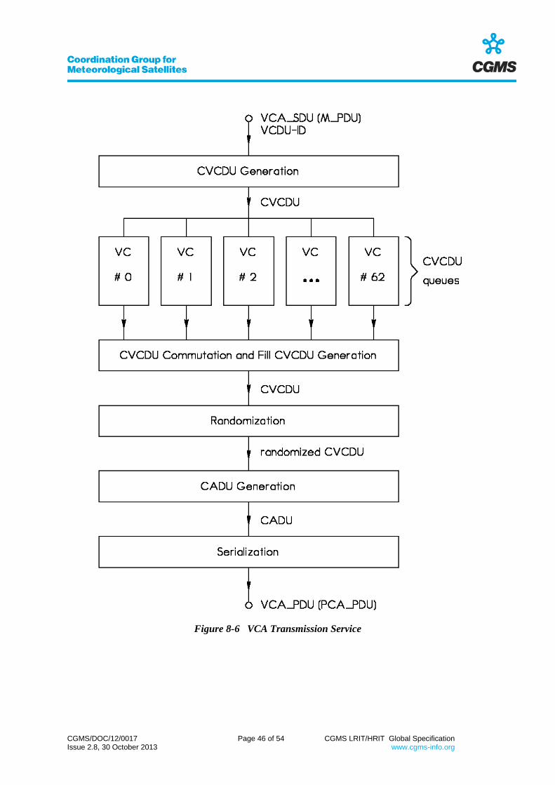
CGMS/DOC/12/0017 Page 46 of 54 CGMS LRIT/HRIT Global Specification Issue 2.8, 30 October 2013 www.cgms-info.org
Figure 8-6 VCA Transmission Service

CGMS/DOC/12/0017 Page 47 of 54 CGMS LRIT/HRIT Global Specification Issue 2.8, 30 October 2013 www.cgms-info.org
8.3.3 Reception Service Specification
8.3.3.1 AOS Syntax
The VCA sublayer service indicates towards the VCLC sublayer the acquisition of a M_PDU:
VCA_UNITDATA.indication (VCA_SDU, VCDU-ID).
The service provides both the service data unit (being one M_PDU) and the VCDU-ID as output.
8.3.3.2 Function
Figure 8-7 provides an overview of the reception service. The incoming serial datastream
(VCA_PDU) is synchronized into discrete CADUs. After this frame synchronization process one
(randomized) CVCDU is extracted from each CADU by means of stripping the synchronization
markers off. Derandomization is performed then by multiplying all 8160 bits of the randomized
CVCDU with a statically defined pseudonoise pattern. The synchronization marker and the
randomization pattern are specified in section 8.3.2.2. After de-randomization each "clear" CVCDU
undergoes a forward error correction based on the Reed-Solomon check symbols included therein
(details are provided in [AD.5]). Optionally the forward error correction may be omitted, requiring an
increased performance of the physical layer (e.g. a bigger antenna) to compensate the FEC gain.
After forward error correction fill VCDUs (those with VC = 63) are discarded. The VCA_SDU is
extracted from the data unit zone of the VCDU, the VCDU-ID is defined in the primary header.
Indication towards the VCLC sublayer is performed by means of the primitive
VCA_UNITDATA.indication (VCA_SDU, VCDU-ID).
8.3.3.3 Optional Functionality
Several optional features may be implemented in the VCA reception service. Here are some
examples:
a) Status and quality of CADU synchronization can be monitored.
b) Fill VCDUs can be analyzed for bit errors before and/or after forward error correction in order
to monitor the performance of the physical link and the performance of the FEC with the actual noise
situation.
c) The VCDU counters can be traced to detect any discontinuity in the VCDU sequence.

CGMS/DOC/12/0017 Page 48 of 54 CGMS LRIT/HRIT Global Specification Issue 2.8, 30 October 2013 www.cgms-info.org
Figure 8-7 VCA Reception Service

CGMS/DOC/12/0017 Page 49 of 54 CGMS LRIT/HRIT Global Specification Issue 2.8, 30 October 2013 www.cgms-info.org
9 PHYSICAL LAYER
The physical layer provides the physical channel service. The service data unit is a serial bitstream.
The PCA_PDU is passed from the data link layer to the physical layer on the transmitting side and
vice versa on the receiving side.
The performance of the physical layer shall be sufficient to ensure a remaining bit error rate not
exceeding 10-8 after applying the forward error correction. The procedure for applying the FEC is
described in section 8.3.3.2 while the algorithm is specified in [AD.5]. One can expect a FEC gain of
4.6 dB for Gaussian channel noise.
The use of concatenated coding i.e. the FEC described in sect. 8.3.3.2 (Reed-Solomon coding)
together with any type of convolution code is mission specific.
The data rate provided by the physical channel determines the mission name, as already indicated in
section 1.5:
- If the data rate is less than 256 kbit/s then the mission is named LRIT.
- If the data rate is greater than or equal 256 kbit/s then the mission is named HRIT.
The implementation of the physical channel is mission specific.

CGMS/DOC/12/0017 Page 50 of 54 CGMS LRIT/HRIT Global Specification Issue 2.8, 30 October 2013 www.cgms-info.org
APPENDIX A - LIST OF ABBREVIATIONS
Acronynm Meaning
AOS Advanced orbiting systems
APID Application process identifier
ASCII American standard code for information interchange
CADU Channel access data unit
CCSDS Consultative Committee for Space Data Systems
CP_PDU CCSDS path protocol data unit
CP_SDU CCSDS path service data unit
CRC Cyclic redundancy check
CVCDU Coded virtual channel data unit
DCT Discrete cosine transformation
EIRP Equivalent isotropic radiance power
ESA European Space Agency
FEC Forward error correction
GTS Global Telecommunication System
G/T Figure of merit
HRIT High Rate Information Transmission
HRUS HRIT User Station
ISO International Organisation for Standardisation
JPEG Joint Photographic Experts Group
LRIT Low Rate Information Transmission
LRPT Low Rate Picture Transmission
LRUS LRIT User Station
LSB Least significant bit
M_PDU Multiplexing service protocol data unit
M_SDU Multiplexing service data unit
MSB Most significant bit
NASA National Aeronautics and Space Administration
NOAA National Oceanic and Atmospheric Administration
NRZ-L Nonreturn-to-zero-Level
NRZ-M Nonreturn-to-zero-Mark
OSI Open systems interconnection
PC_SDU Physical channel service data unit

CGMS/DOC/12/0017 Page 51 of 54 CGMS LRIT/HRIT Global Specification Issue 2.8, 30 October 2013 www.cgms-info.org
PCA_PDU Physical channel access protocol data unit
PN Pseudonoise
RX Reception
S/C Spacecraft
SDU Service data unit
S_PDU Session protocol data unit
S_SDU Session service data unit
TP_PDU Transport protocol data unit
TP_PRIO Transport priority
TP_SDU Transport service data unit
TX Transmission
UTC Coordinated universal time
VC Virtual channel
VC_PDU Virtual channel protocol data unit
VCA Virtual channel access
VCA_SAP Virtual channel access service access point
VCA_SDU Virtual channel access service data unit
VCDU Virtual channel data unit
VCDU-ID Virtual channel data unit identifier
VCLC Virtual channel link control
VCLC_SAP Virtual channel link control service access point
WEFAX Weather Facsimile
WMO World Meteorological Organisation

CGMS/DOC/12/0017 Page 52 of 54 CGMS LRIT/HRIT Global Specification Issue 2.8, 30 October 2013 www.cgms-info.org
APPENDIX B - DATA TYPES
B.1 Unsigned Integer
An unsigned integer is a data structure of n bit length with n being a multiple of 8. Its value is
determined by the binary representation of the bits therein, where the first bit is the MSB and the last
is the LSB. The value ranges from 0 to 2n-1.
B.2 Signed Integer
A signed integer is a data structure of n bit length with n being a multiple of 8. The first bit is the
MSB, the last bit is the LSB. With N being the (unsigned) binary representation of the bits therein, the
value is determined as follows: If the MSB equals 0 then the value equals N. Else (i.e. MSB = 1) the
value is 2n-N. Consequently the value ranges from -2
n-1 to 2
n-1-1.
B.3 Character
A character string consists of a sequence of one or more octets, each of them representing one
character. The binary value of each octets determines the character, international alphabet no. 5 is
used as code. Figure B-1 shows the code table, where the binary value is N = 16 × X + Y. Note that
values beyond 127 are not used.
B.4 CCSDS Time
Within LRIT/HRIT the CCSDS day segmented time code is used. The data structure is six octets in
length, where the first two octets (16 bits) represent the day and the last four octets (32 bits) represent
the ms of day. The day code epoch is 1-Jan-1958.
The preamble code (which is not transmitted) of the implemented code is 01000000 (binary).
Note that all date and time information is based on the UTC time scale.

CGMS/DOC/12/0017 Page 53 of 54 CGMS LRIT/HRIT Global Specification Issue 2.8, 30 October 2013 www.cgms-info.org
X
0 1 2 3 4 5 6 7
0 <NUL> <DLE> <SP> 0 @ P ` p
1 <SOH> <DC1> ! 1 A Q a q
2 <STX> <DC2> “ 2 B R b r
3 <ETX> <DC3> # 3 C S c s
4 <EOT> <DC4> $ 4 D T d t
5 <ENQ> <NAK> % 5 E U e u
6 <ACK> <SYN> & 6 F V f v
Y 7 <BEL> <ETB> ´ 7 G W g w
8 <BS> <CAN> ( 8 H X h x
9 <HT> <EM> ) 9 I Y i y
A <LF> <SUB> * : J Z j z
B <VT> <ESC> + ; K [ k {
C <FF> <IS4> , < L \ l |
D <CR> <IS3> - = M ] m }
E <SO> <IS2> . > N ^ n ~
F <SI> <IS1> / ? O _ o <DEL>
Figure B-1 Character Code Table

CGMS/DOC/12/0017 Page 54 of 54 CGMS LRIT/HRIT Global Specification Issue 2.8, 30 October 2013 www.cgms-info.org
APPENDIX C - LIST OF MISSION SPECIFIC ITEMS
Section Item
3 Specification of the application layer
4.2 Mission specific file types (if any)
4.2 Mission specific header records (if any)
4.2.3.4 Details on encryption key message files (if used)
4.4.3 Mission specific projection functions (if any)
5.2 Details on encryption (if used)
5.3 Selection of JPEG compression method
Selection of mission specific compression method
5.4 Data sequencing function
5.5 Usage of priorities
7.2.2 Spacecraft identifier
9 Specification of the physical layer
Note that any mission using this global LRIT/HRIT specification has to determine the above
mentioned items. However, more information may be required to specify the mission sufficiently.