cool - mesteksa.commesteksa.com/fileuploads/literature/applied air/evaporative cooling... · aztec...
TRANSCRIPT

Direct, Indirect and Indirect/DirectEvaporative Cooling Units
Cool
Keeping Mission
Critical Facilities
TGMCC-1
Technical Guide for:
• MCC Low Operating Cost, High Effi ciency, Environmentally Friendly Evaporative Cooling Units

2

3
TABLE OF CONTENTS
How To Use This Guide ........................................................................................................................................................................ 4What is Evaporative Cooling ............................................................................................................................................................... 4How Much Cooling can I Get ............................................................................................................................................................... 5Typical Design Conditions Chart .......................................................................................................................................................... 6Direct Evaporative Cooling ................................................................................................................................................................... 7Indirect Evaporative Cooling ................................................................................................................................................................ 8Indirect Evaporative Cooling with Hot Aisle Return ......................................................................................................................... 9Indirect/Direct Evaporative Cooling ................................................................................................................................................. 10Alton HECD Features and Options .................................................................................................................................................... 11Alton HECD Air Performance Chart .................................................................................................................................................. 12Alton HECD Amp Draw Table ............................................................................................................................................................. 13Alton HECD Dimensions – Basic Unit ..........................................................................................................................................14-15Alton HECD Dimensions – Basic Unit with Mixing Section .....................................................................................................16-17Alton HECD Typical Wiring ............................................................................................................................................................18-19Alton HECD Typical Specifi cations ................................................................................................................................................... 20Aztec ASC Model Designation .......................................................................................................................................................... 21Aztec ASC Features and Options ...................................................................................................................................................... 22Aztec ASC Equipment Data Chart ..................................................................................................................................................... 23Aztec ASC Blower Performance Chart with Standard Arrangement Fan(s) ........................................................................24-25Aztec ASC Blower Performance Chart for Fan Array ...............................................................................................................26-27Aztec ASC Blower Performance Chart for Fan Array with 100% Redundancy ....................................................................28-29Aztec ASC Amp Draw Table ............................................................................................................................................................... 30Aztec ASC Fan Effi ciency ................................................................................................................................................................... 31Aztec ASC Dimensions for Standard Arrangement Fan(s) with End Discharge ..................................................................32-33Aztec ASC Dimensions for Standard Arrangement Fan(s) with Down Discharge ..............................................................34-35Aztec ASC Dimensions for Fan Array with End Discharge ......................................................................................................36-37Aztec ASC Dimensions for Fan Array with Down Discharge ..................................................................................................38-39Aztec ASC Dimensions for Roof Curb ............................................................................................................................................... 40Aztec ASC Typical Piping .................................................................................................................................................................... 41Aztec ASC Control Systems ..........................................................................................................................................................42-43Aztec ASC Typical Wiring ..............................................................................................................................................................44-45Aztec ASC Typical Specifi cations ................................................................................................................................................46-47

4
HOW TO USE THIS GUIDE
We offer two different system types of evaporative cooling units. These consist of an Alton Direct Evaporative Cooling Unit (DEC) or an Aztec series that can be set up as either an Indirect or Indirect/Direct Unit (IDEC). To help you understand which type of unit we are talking about throughout this Technical Guide; we will use or Identifi cation Blocks on the page headings. If you see the IDEC block at the top of a page you will know that the
WHAT IS EVAPORATIVE COOLING?
Evaporative Cooling is the oldest form of cooling known to man and occurs in nature every day. Whenever water is evaporated, heat is absorbed. Wet the back of your hand, then blow on it. The skin surface is immediately cooler. This demonstrates the basic principle of evaporative cooling. Cooling nature’s way with water eliminates the cost of expensive refrigeration systems and reduces operating cost and maintenance costs. History shows that the ancient Egyptians used this principle to keep themselves cool. Direct evaporative cooling is an adiabatic process where the dry bulb temperature is lowered without changing the amount of heat
IDECDEC
DEC
IDEC
in the air. This adiabatic cooling process is also used to create the chilled water that feeds our indirect evaporative cooling coil. Indirect evaporative cooling can be used to lower both the dry bulb and wet bulb temperatures.
Choosing an evaporative cooling system offers a substantial energy cost savings. Leadership in Energy and Environmental Design (LEED) points can be achieved by using cooling options that operate more effi ciently than LEED thresholds.
information refers to the Alton Direct Evaporative Cooling Series. And if you see the block at the top of a page you will know that the information refers to the Aztec Indirect or Indirect/Direct Evaporative Cooling Series. Some pages have both of these blocks at the top of a page. The information shown here is general information that pertains to both types of units.

5
HOW MUCH COOLING CAN I GET?
The amount of cooling we can get from an evaporative cooling unit varies from area to area. The more difference you have between your Entering Dry Bulb (EDB) and Entering Wet Bulb (EWB) temperatures, the greater the cooling effect.
The formula to determine Leaving Dry Bulb (LDB) temperature for Direct Evaporative Cooling Units is:
LDB = EDB – ((SE x (EDB – EWB))LDB = Leaving Air Dry Bulb temperatureEDB = Entering Air Dry Bulb temperatureEWB = Entering Air Wet Bulb temperatureSE = Saturation Effectiveness (see chart below).
Example: Calculate the leaving air dry bulb temperature for a 20,000 CFM unit with 100° entering dry bulb and 80° entering wet bulb temperatures.
Solution: Air Delivery Table on page 12 shows we would use a HECD-210 for 20,000 CFM requirement. Chart shows this model has 32.9 sq. ft. of cooling media. 20,000 CFM divided by 32.0 sq. ft. of media equals 607 FPM velocity across cooling media. Chart below shows 87% Saturation Effectiveness at 607 FPM.
LDB = 100° - ((0.87 x (100° - 80°) = 82.6°
For Direct Evaporative Cooling units the Wet Bulb temperature will not change.
The formula to determine Leaving Dry Bulb (LDB) temperature for Indirect Evaporative Cooling Units is:
LDB = EDB – ((SE x (EDB – EWB))LDB = Leaving Air Dry Bulb temperatureEDB = Entering Air Dry Bulb temperatureEWB = Entering Air Wet Bulb temperatureSE = Saturation Effectiveness (use 0.75)
Example: Calculate the leaving air dry bulb temperature for a 20,000 CFM unit with 100° entering dry bulb and 80° entering wet bulb temperatures.
Solution:
LDB = 100° - ((0.75 x (100° - 80°) = 85°
The use of a Psychrometric Chart is required to determine wet bulb temperature.
Air Velocity (FPM)
Typi
cal E
vapo
rativ
e Co
olin
g Ef
fi cie
ncy
(Dot
ted
Line
)Typical A
ir Pressure Drop ("W
.C.) (Solid Line)IDEC
DEC

6
TYPICAL DESIGN CONDITIONS CHART
State City DB °F WB °FAL Birmingham 95 78
Flagstaff 86 61Phoenix 110 76Tucson 105 72Fort Smith 99 79Little Rock 98 80Bakersfield 104 73Los Angeles 84 70Sacramento 100 72San Diego 85 73San Francisco 83 65Denver 93 65Grand Junction 97 65Pueblo 98 68Jacksonville 95 80Orlando 94 79Pensacola 94 81
GA Atlanta, GA 94 77Boise 97 66Coeur d'Alene 91 65Chicago 92 79Decatur 93 79Rockford 91 78Evansville 94 79Indianapolis 91 78South Bend 90 77Des Moines 93 78Dubuque 89 78Salina 101 77Wichita 101 77Bowling Green 93 78Lexington 91 77Louisville 93 79Paducah 95 80New Orleans 94 81Shreveport 97 80Detroit 90 77Grand Rapids 89 76Saginaw 90 77Minneapolis 91 77Rochester 88 76Kansas City 96 79Springfield 95 78St Louis 95 79
KS
FL
IL
MO
KY
MI
ID
AZ
IN
IA
LA
MN
AR
CA
CO
State City DB °F WB °FBillings 94 66Great Falls 91 64Lincoln 97 78Omaha 96 78Las Vegas 108 71Reno 95 63
NM Albuquerque, NM 96 65Albany 88 75Buffalo 86 74New York City 89 77Greensboro 92 77Raleigh 94 78Bismarck 93 74Fargo 91 75Cincinnati 93 78Cleveland 89 76Columbus 91 77Oklahoma City 99 77Tulsa 100 79Pendleton 96 67Portland 91 69Philadelphia 93 78Pittsburgh 89 75Columbia 97 78Greenville 94 77Rapid City 95 71Sioux Falls 93 77Knoxville 92 77Memphis 96 80Nashville 94 78Amarillo 97 71Dallas 101 78El Paso 101 70Houston 97 80San Antonio 98 78
UT Salt Lake City 97 67Richmond 95 79Roanoke 92 75Seattle 85 66Spokane 92 65Madison 90 77Milwaukee 90 77Casper 93 63Cheyenne 88 63
NE
NV
NY
NC
ND
OH
OK
OR
PA
SC
SD
TX
VA
WA
MT
WY
WI
TN
IDEC
DEC

7
EAWB
°FWB DB WB DB WB DB WB DB WB DB WB DB WB DB WB DB WB
56 58.9 56.0 59.5 56.0 60.1 56.0 60.7 56.0
58 60.6 58.0 61.2 58.0 61.8 58.0 62.4 58.0 63.0 58.0
60 62.4 60.0 63.0 60.0 63.6 60.0 64.2 60.0 64.8 60.0 65.4 60.0
62 64.2 62.0 64.8 62.0 65.4 62.0 66.0 62.0 66.6 62.0 67.2 62.0 67.8 62.0
64 65.9 64.0 66.5 64.0 67.1 64.0 67.7 64.0 68.3 64.0 68.9 64.0 69.5 64.0 70.1 64.0
66 67.7 66.0 68.3 66.0 68.9 66.0 69.5 66.0 70.1 66.0 70.7 66.0 71.3 66.0 71.9 66.0
68 69.4 68.0 70.0 68.0 70.6 68.0 71.2 68.0 71.8 68.0 72.4 68.0 73.0 68.0 73.6 68.0
70 71.2 70.0 71.8 70.0 72.4 70.0 73.0 70.0 73.6 70.0 74.2 70.0 74.8 70.0 75.4 70.0
72 73.0 72.0 73.6 72.0 74.2 72.0 74.8 72.0 75.4 72.0 76.0 72.0 76.6 72.0 77.2 72.0
74 74.7 74.0 75.3 74.0 75.9 74.0 76.5 74.0 77.1 74.0 77.7 74.0 78.3 74.0 78.9 74.0
76 76.5 76.0 77.1 76.0 77.7 76.0 78.3 76.0 78.9 76.0 79.5 76.0 80.1 76.0 80.7 76.0
78 78.2 78.0 78.8 78.0 79.4 78.0 80.0 78.0 80.6 78.0 81.2 78.0 81.8 78.0 82.4 78.0
80 80.0 80.0 80.6 80.0 81.2 80.0 81.8 80.0 82.4 80.0 83.0 80.0 83.6 80.0 84.2 80.0
82 82.4 82.0 83.0 82.0 83.6 82.0 84.2 82.0 84.8 82.0 85.4 82.0 86.0 82.0
84 84.1 84.0 84.7 84.0 85.3 84.0 85.9 84.0 86.5 84.0 87.1 84.0 87.7 84.0
Notes:1. Direct evaporative cooling performance is based on 88% saturation efficiency.
EAWB
°FWB KW BTU KW BTU KW BTU KW BTU KW BTU KW BTU KW BTU KW BTU
56 6.7 22,810 8.1 27,562 9.5 32,314 10.9 37,066 12.3 41,818 13.6 46,570 15.0 51,322 16.4 56,074
58 6.1 20,909 7.5 25,661 8.9 30,413 10.3 35,165 11.7 39,917 13.1 44,669 14.5 49,421 15.9 54,173
60 5.6 19,008 7.0 23,760 8.4 28,512 9.7 33,264 11.1 38,016 12.5 42,768 13.9 47,520 15.3 52,272
62 5.0 17,107 6.4 21,859 7.8 26,611 9.2 31,363 10.6 36,115 12.0 40,867 13.4 45,619 14.8 50,371
64 4.5 15,206 5.8 19,958 7.2 24,710 8.6 29,462 10.0 34,214 11.4 38,966 12.8 43,718 14.2 48,470
66 3.9 13,306 5.3 18,058 6.7 22,810 8.1 27,562 9.5 32,314 10.9 37,066 12.3 41,818 13.6 46,570
68 3.3 11,405 4.7 16,157 6.1 20,909 7.5 25,661 8.9 30,413 10.3 35,165 11.7 39,917 13.1 44,669
70 2.8 9,504 4.2 14,256 5.6 19,008 7.0 23,760 8.4 28,512 9.7 33,264 11.1 38,016 12.5 42,768
72 2.2 7,603 3.6 12,355 5.0 17,107 6.4 21,859 7.8 26,611 9.2 31,363 10.6 36,115 12.0 40,867
74 1.7 5,702 3.1 10,454 4.5 15,206 5.8 19,958 7.2 24,710 8.6 29,462 10.0 34,214 11.4 38,966
76 1.1 3,802 2.5 8,554 3.9 13,306 5.3 18,058 6.7 22,810 8.1 27,562 9.5 32,314 10.9 37,066
78 0.6 1,901 1.9 6,653 3.3 11,405 4.7 16,157 6.1 20,909 7.5 25,661 8.9 30,413 10.3 35,165
80 1.4 4,752 2.8 9,504 4.2 14,256 5.6 19,008 7.0 23,760 8.4 28,512 9.7 33,264
82 0.8 2,851 2.2 7,603 3.6 12,355 5.0 17,107 6.4 21,859 7.8 26,611 9.2 31,363
84 0.3 950 1.7 5,702 3.1 10,454 4.5 15,206 5.8 19,958 7.2 24,710 8.6 29,462
Notes:1. Direct evaporative cooling performance is based on 88% saturation efficiency.
THERMAL PERFORMANCE Per 1,000 CFMEntering Air Temperature Dry Bulb Temp. (EADB)
80° F 85° F 90° F 95° F 100° F 105° F 110° F 115° F
Direct – Water is in direct contact with the airstream. The dry bulb temperature is lowered but the wet bulb temperature remains constant which raises the Relative Humidity in the airstream.
LEAVING AIR TEMPERATURESEntering Air Temperature Dry Bulb Temp. (EADB)
80° F 85° F 90° F 95° F 100° F 105° F 110° F 115° F
DIRECT EVAPORATIVE COOLING
DEC

8
EAWB
°FWB DB WB DB WB DB WB DB WB DB WB DB WB DB WB DB WB56 62.0 48.2 63.3 46.6 64.5 44.7 65.8 42.658 63.5 51.1 64.8 49.5 66.0 47.5 67.3 46.1 68.5 44.060 65.0 54.2 66.3 52.8 67.5 51.0 68.8 49.2 70.0 47.6 71.3 46.062 66.5 57.1 67.8 55.6 69.0 54.1 70.3 52.2 71.5 50.9 72.8 49.4 74.0 47.664 68.0 59.8 69.3 58.4 70.5 57.1 71.8 55.4 73.0 53.9 74.3 52.6 75.5 50.8 76.8 49.266 69.5 62.3 70.8 61.1 72.0 59.6 73.3 58.4 74.5 56.8 75.8 55.5 77.0 54.1 78.3 52.368 71.0 65.0 72.3 63.8 73.5 62.3 74.8 61.0 76.0 59.8 77.3 58.4 78.5 57.0 79.8 55.570 72.5 67.8 73.8 66.6 75.0 65.1 76.3 63.9 77.5 62.8 78.8 61.4 80.0 60.0 81.3 59.072 74.0 71.0 75.3 69.0 76.5 68.0 77.8 66.8 79.0 65.6 80.3 64.4 81.5 63.1 82.8 61.774 75.5 72.7 76.8 71.6 78.0 70.5 79.3 69.4 80.5 68.2 81.8 67.1 83.0 66.0 84.3 64.876 77.0 74.8 78.3 74.1 79.5 73.0 80.8 71.9 82.0 71.0 83.3 69.9 84.5 68.8 85.8 67.678 78.5 77.6 79.8 76.8 81.0 75.8 82.3 74.7 83.5 73.6 84.8 72.5 86.0 71.5 87.3 70.480 80.0 80.0 81.3 79.2 82.5 78.2 83.8 77.3 85.0 76.4 86.3 75.5 87.5 74.4 88.8 73.382 82.8 81.5 84.0 80.5 85.3 79.6 86.5 78.8 87.8 77.9 89.0 77.0 90.3 76.284 84.3 83.9 85.5 82.9 86.8 81.9 88.0 81.1 89.3 80.2 90.5 79.3 91.8 78.5
Notes:1. Indirect evaporative cooling performance is based on 75% saturation efficiency.
EAWB
°FWB KW BTU KW BTU KW BTU KW BTU KW BTU KW BTU KW BTU KW BTU56 5.7 19,440 6.9 23,490 8.1 27,540 9.3 31,590 - - - - - - - -
58 5.2 17,820 6.4 21,870 7.6 25,920 8.8 29,970 10.0 34,020 - - - - - -
60 4.7 16,200 5.9 20,250 7.1 24,300 8.3 28,350 9.5 32,400 10.7 36,450 - - - -
62 4.3 14,580 5.5 18,630 6.6 22,680 7.8 26,730 9.0 30,780 10.2 34,830 11.4 38,880 - -
64 3.8 12,960 5.0 17,010 6.2 21,060 7.4 25,110 8.5 29,160 9.7 33,210 10.9 37,260 12.1 41,310
66 3.3 11,340 4.5 15,390 5.7 19,440 6.9 23,490 8.1 27,540 9.3 31,590 10.4 35,640 11.6 39,690
68 2.8 9,720 4.0 13,770 5.2 17,820 6.4 21,870 7.6 25,920 8.8 29,970 10.0 34,020 11.2 38,070
70 2.4 8,100 3.6 12,150 4.7 16,200 5.9 20,250 7.1 24,300 8.3 28,350 9.5 32,400 10.7 36,450
72 1.9 6,480 3.1 10,530 4.3 14,580 5.5 18,630 6.6 22,680 7.8 26,730 9.0 30,780 10.2 34,830
74 1.4 4,860 2.6 8,910 3.8 12,960 5.0 17,010 6.2 21,060 7.4 25,110 8.5 29,160 9.7 33,210
76 0.9 3,240 2.1 7,290 3.3 11,340 4.5 15,390 5.7 19,440 6.9 23,490 8.1 27,540 9.3 31,590
78 0.5 1,620 1.7 5,670 2.8 9,720 4.0 13,770 5.2 17,820 6.4 21,870 7.6 25,920 8.8 29,970
80 - 86,400 1.2 4,050 2.4 8,100 3.6 12,150 4.7 16,200 5.9 20,250 7.1 24,300 8.3 28,350
82 - - 0.7 2,430 1.9 6,480 3.1 10,530 4.3 14,580 5.5 18,630 6.6 22,680 7.8 26,730
84 - - 0.2 810 1.4 4,860 2.6 8,910 3.8 12,960 5.0 17,010 6.2 21,060 7.4 25,110
Notes:1. Indirect evaporative cooling performance is based on 75% saturation efficiency.
Indirect – Water is never in contact with the airstream. Both the dry bulb and wet bulb temperatures are lowered. This is straight sensible cooling, which is ideal to offset the load in a data center.
LEAVING AIR TEMPERATURESEntering Air Temperature Dry Bulb Temp. (EADB)
80° F 85° F 90° F 95° F 100° F 105° F
110° F 115° F
110° F 115° F
THERMAL PERFORMANCE Per 1,000 CFMEntering Air Temperature Dry Bulb Temp. (EADB)
80° F 85° F 90° F 95° F 100° F 105° F
INDIRECT EVAPORATIVE COOLING WITH 100% OUTSIDE AIR
IDEC

9
90/67 95/71 100/74 105/78 110/81 115/85 120/89 125/92 130/96
56 64/58 65/62 66/65 67/69 72/71 75/75 79/78 82/81 86/85
58 66/59 67/62 68/66 69/69 72/72 76/75 79/79 82/81 86/85
60 67/59 68/62 69/66 70/70 72/72 76/76 80/79 83/82 87/86
62 69/60 70/63 71/66 72/71 73/73 77/76 80/80 83/82 87/86
64 71/60 72/64 72/66 73/71 74/73 77/77 81/80 84/83 88/86
66 72/61 73/64 74/66 75/71 76/73 77/77 82/81 84/83 88/87
68 74/62 75/65 76/67 77/71 78/73 78/78 82/81 85/84 89/88
70 75/62 76/65 77/67 78/71 79/73 80/78 82/82 85/84 89/88
72 77/63 78/66 79/68 80/71 81/74 82/78 83/82 86/85 89/89
74 79/63 80/66 81/68 81/72 82/74 83/78 84/83 86/85 90/89
76 80/64 81/67 82/69 83/72 84/75 85/78 86/83 87/86 90/89
78 82/64 83/67 84/69 85/73 86/75 86/79 87/83 88/86 90/90
80 84/65 84/68 85/70 86/73 87/75 88/79 89/83 90/86 91/90
82 85/66 86/68 87/70 88/74 89/76 90/79 91/83 91/86 92/90
84 87/66 88/69 89/71 90/74 90/76 91/80 92/83 93/86 94/91
90/75 95/79 100/83 105/87 110/91 115/96 120/100 125/104 130/108
56 68/68 71/71 75/74 78/78 82/81 86/86 90/90 94/94 98/98
58 69/68 72/72 75/75 79/78 82/82 87/86 91/90 95/94 99/98
60 70/69 73/72 76/75 79/79 83/82 87/87 91/91 95/95 99/98
62 70/70 73/73 76/76 80/79 83/83 88/87 92/91 96/95 99/99
64 71/70 74/73 77/76 80/80 84/83 89/88 92/92 96/96 100/99
66 72/71 74/74 78/77 81/80 84/84 89/89 93/92 97/96 100/99
68 74/71 75/74 78/78 81/81 85/84 90/89 93/93 97/96 100/100
70 75/71 76/75 79/78 82/81 86/85 90/90 94/93 97/97 101/100
72 77/71 78/75 79/79 83/82 86/85 91/90 94/94 98/97 101/100
74 79/72 80/75 81/79 83/83 87/86 91/91 95/94 98/98 101/101
76 80/72 81/76 82/79 83/83 87/86 92/91 95/95 99/98 101/101
78 82/73 83/76 84/79 85/83 87/87 92/92 96/95 99/99 101/101
80 84/73 84/76 85/80 86/83 88/87 93/92 96/96 100/99 101/101
82 85/74 86/77 87/80 88/84 89/88 93/92 97/96 100/99 101/101
84 87/74 88/77 89/81 90/84 90/88 93/92 97/96 100/99 102/101
LEAVING AIR TEMPERATURES
LEAVING AIR TEMPERATURES
Ambient WetBulb Temp
Ambient WetBulb Temp
Return Air Temperature at 30% RH
Return Air Temperature at 50% RH
INDIRECT EVAPORATIVE COOLING WITH 100% RETURN AIR
IDEC
Indirect – Water is never in contact with the airstream. Both the dry bulb and wet bulb temperatures are lowered. This is straight sensible cooling, which is ideal to offset the load in a data center.

10
EAWB
°FWB DB WB DB WB DB WB DB WB DB WB DB WB DB WB DB WB56 49.9 48.2 48.6 46.6 47.1 44.7 45.4 42.658 52.6 51.1 51.3 49.5 49.7 47.5 48.6 46.1 46.9 44.060 55.5 54.2 54.4 52.8 53.0 51.0 51.5 49.2 50.3 47.6 49.0 46.062 58.2 57.1 57.1 55.6 55.9 54.1 54.4 52.2 53.4 50.9 52.2 49.4 50.8 47.664 60.8 59.8 59.7 58.4 58.7 57.1 57.4 55.4 56.2 53.9 55.2 52.6 53.8 50.8 52.5 49.266 63.2 62.3 62.3 61.1 61.1 59.6 60.2 58.4 58.9 56.8 57.9 55.5 56.8 54.1 55.4 52.368 65.7 65.0 64.8 63.8 63.6 62.3 62.7 61.0 61.7 59.8 60.7 58.4 59.6 57.0 58.4 55.570 68.4 67.8 67.5 66.6 66.3 65.1 65.4 63.9 64.6 62.8 63.5 61.4 62.4 60.0 61.7 59.072 71.4 71.0 69.8 69.0 69.0 68.0 68.1 66.8 67.2 65.6 66.3 64.4 65.3 63.1 64.2 61.774 73.0 72.7 72.2 71.6 71.4 70.5 70.6 69.4 69.7 68.2 68.9 67.1 68.0 66.0 67.1 64.876 75.1 74.8 74.6 74.1 73.8 73.0 73.0 71.9 72.3 71.0 71.5 69.9 70.7 68.8 69.8 67.678 77.7 77.6 77.2 76.8 76.4 75.8 75.6 74.7 74.8 73.6 74.0 72.5 73.2 71.5 72.4 70.480 80.0 80.0 79.4 79.2 78.7 78.2 78.1 77.3 77.4 76.4 76.8 75.5 76.0 74.4 75.2 73.382 81.7 81.5 80.9 80.5 80.3 79.6 79.7 78.8 79.1 77.9 78.4 77.0 77.9 76.284 83.9 83.9 83.2 82.9 82.5 81.9 81.9 81.1 81.3 80.2 80.6 79.3 80.1 78.5
Notes:1. Indirect evaporative cooling performance is based on 75% saturation efficiency.2. Direct evaporative cooling performance is based on 88% saturation efficiency.
EAWB
°FWB KW BTU KW BTU KW BTU KW BTU KW BTU KW BTU KW BTU KW BTU56 9.5 32,556 11.5 39,314 13.6 46,358 15.7 53,592 - - - - - - - -58 8.7 29,605 10.7 36,364 12.7 43,502 14.7 50,071 16.8 57,305 - - - - - -60 7.8 26,464 9.7 33,033 11.7 39,982 13.8 46,930 15.7 53,689 17.7 60,448 - - - -62 6.9 23,514 8.8 30,177 10.8 36,841 12.9 43,885 14.8 50,358 16.7 57,022 18.7 63,971 - -64 6.1 20,753 8.0 27,322 9.9 33,795 11.9 40,649 13.9 47,313 15.8 53,786 17.8 60,735 19.8 67,494 66 5.3 18,183 7.2 24,561 9.2 31,225 11.0 37,603 13.0 44,362 14.9 50,836 16.8 57,404 18.9 64,353 68 4.5 15,422 6.4 21,801 8.3 28,464 10.2 34,938 12.1 41,316 14.0 47,885 16.0 54,454 17.9 61,117 70 3.7 12,567 5.6 18,945 7.5 25,609 9.4 31,987 11.2 38,271 13.1 44,839 15.1 51,408 16.9 57,596 72 2.7 9,331 4.8 16,470 6.6 22,658 8.5 29,037 10.4 35,415 12.2 41,794 14.1 48,267 16.1 54,836 74 2.2 7,521 4.0 13,805 5.9 20,088 7.7 26,371 9.6 32,750 11.4 39,033 13.3 45,317 15.2 51,695 76 1.6 5,331 3.3 11,234 5.1 17,518 7.0 23,801 8.8 29,894 10.6 36,178 12.4 42,461 14.3 48,840 78 0.7 2,475 2.5 8,474 4.3 14,662 6.1 20,946 8.0 27,229 9.8 33,512 11.6 39,701 13.5 45,984 80 - - 1.8 5,998 3.6 12,187 5.4 18,280 7.1 24,373 8.9 30,467 10.8 36,750 12.6 43,034 82 - - 1.1 3,618 2.9 9,806 4.7 15,900 6.4 21,898 8.2 27,991 10.0 34,085 11.7 40,083 84 - - 0.3 1,143 2.1 7,331 4.0 13,519 5.7 19,518 7.5 25,611 9.3 31,704 11.0 37,703
Notes:1. Indirect evaporative cooling performance is based on 75% saturation efficiency.2. Direct evaporative cooling performance is based on 88% saturation efficiency.
Indirect/Direct – This is a two-stage hybrid approach using both systems described above. The first stage is the Indirect section which will lower dry bulb and wet bulb temperatures. The second stage is the Direct section that further lowers the dry bulb temperature using the leaving air of the Indirect section as the starting point.
LEAVING AIR TEMPERATURESEntering Air Temperature Dry Bulb Temp. (EADB)
80° F 85° F 90° F 95° F 100° F
105° F 110° F 115° F
105° F 110° F 115° F
THERMAL PERFORMANCE Per 1,000 CFMEntering Air Temperature Dry Bulb Temp. (EADB)
80° F 85° F 90° F 95° F 100° F
INDIRECT/DIRECT EVAPORATIVE COOLING
IDEC
11
B
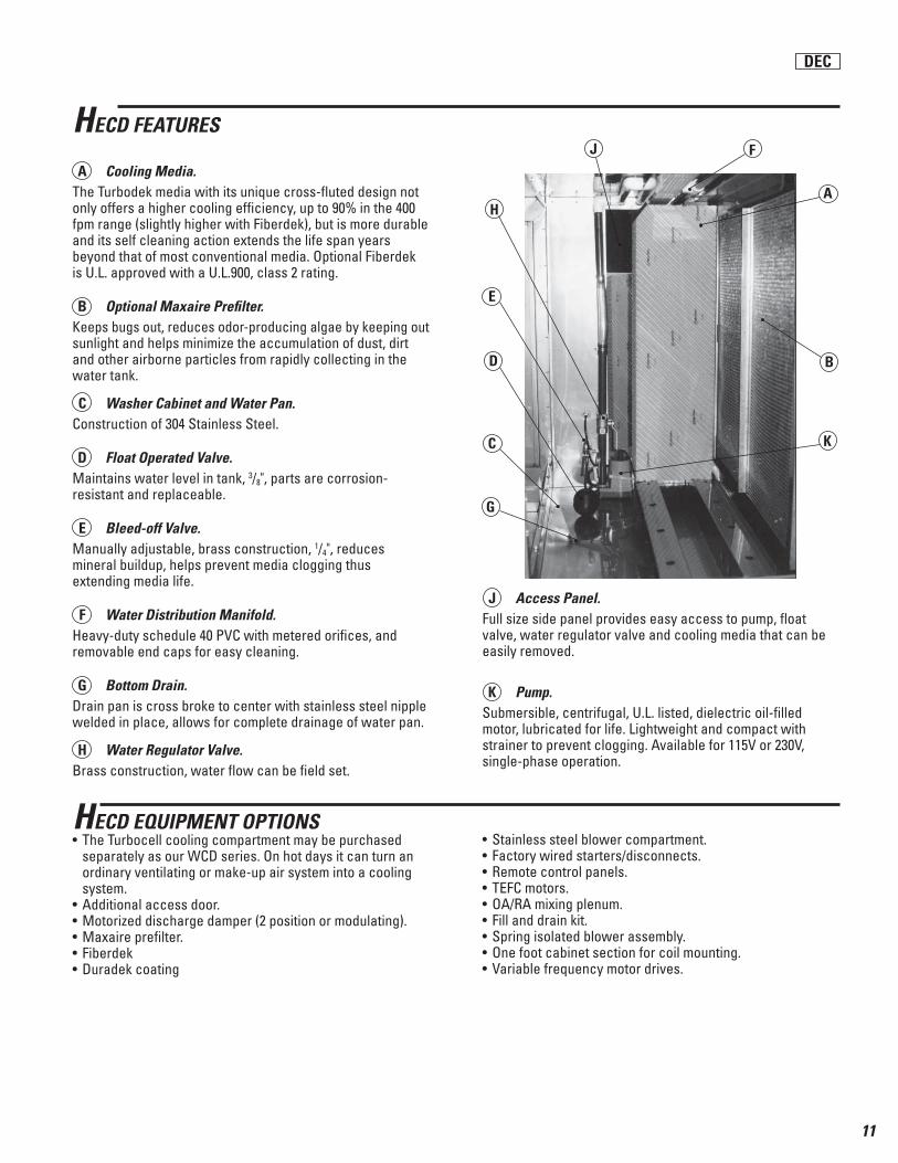
HECD FEATURES
A Cooling Media. The Turbodek media with its unique cross-fl uted design not only offers a higher cooling effi ciency, up to 90% in the 400 fpm range (slightly higher with Fiberdek), but is more durable and its self cleaning action extends the life span years beyond that of most conventional media. Optional Fiberdek is U.L. approved with a U.L.900, class 2 rating.
B Optional Maxaire Prefi lter. Keeps bugs out, reduces odor-producing algae by keeping out sunlight and helps minimize the accumulation of dust, dirt and other airborne particles from rapidly collecting in the water tank.
C Washer Cabinet and Water Pan.Construction of 304 Stainless Steel.
D Float Operated Valve.Maintains water level in tank, 3/8", parts are corrosion-resistant and replaceable.
E Bleed-off Valve.Manually adjustable, brass construction, 1/4", reduces mineral buildup, helps prevent media clogging thus extending media life.
F Water Distribution Manifold. Heavy-duty schedule 40 PVC with metered orifi ces, and removable end caps for easy cleaning.
G Bottom Drain.Drain pan is cross broke to center with stainless steel nipple welded in place, allows for complete drainage of water pan.
H Water Regulator Valve. Brass construction, water fl ow can be fi eld set.
J Access Panel.Full size side panel provides easy access to pump, fl oat valve, water regulator valve and cooling media that can be easily removed.
K Pump. Submersible, centrifugal, U.L. listed, dielectric oil-fi lled motor, lubricated for life. Lightweight and compact with strainer to prevent clogging. Available for 115V or 230V, single-phase operation.
H
E
D
C
G
J
K
A
F
• Stainless steel blower compartment.• Factory wired starters/disconnects.• Remote control panels.• TEFC motors.• OA/RA mixing plenum.• Fill and drain kit.• Spring isolated blower assembly.• One foot cabinet section for coil mounting.• Variable frequency motor drives.
HECD EQUIPMENT OPTIONS• The Turbocell cooling compartment may be purchased separately as our WCD series. On hot days it can turn an ordinary ventilating or make-up air system into a cooling system.• Additional access door.• Motorized discharge damper (2 position or modulating).• Maxaire prefi lter.• Fiberdek• Duradek coating
DEC
12
BLOWER HORSEPOWER AND SPEED REQD. @ ESP (W.C.) 0.125" 0.25" 0.50" 0.75" 1.00" 1.25" 1.50" HP RPM HP RPM HP RPM HP RPM HP RPM HP RPM HP RPM
CFM MODELNO.
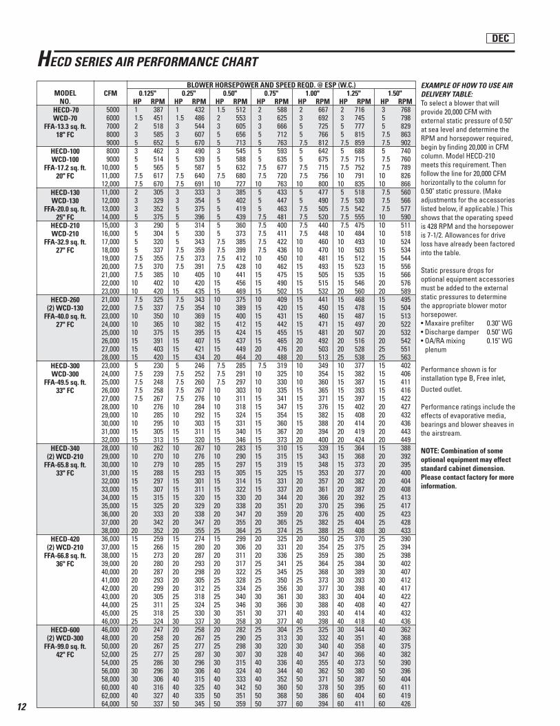
EXAMPLE OF HOW TO USE AIR DELIVERY TABLE:To select a blower that will provide 20,000 CFM with external static pressure of 0.50" at sea level and determine the RPM and horsepower required, begin by fi nding 20,000 in CFM column. Model HECD-210 meets this requirement. Then follow the line for 20,000 CFM horizontally to the column for 0.50" static pressure. (Make adjustments for the accessories listed below, if applicable.) This shows that the operating speed is 428 RPM and the horsepower is 7-1/2. Allowances for drive loss have already been factored into the table.
Static pressure drops for optional equipment accessories must be added to the external static pressures to determine the appropriate blower motor horsepower.• Maxaire prefi lter 0.30" WG• Discharge damper 0.50" WG• OA/RA mixing 0.15" WG plenum
Performance shown is for installation type B, Free inlet, Ducted outlet.
Performance ratings include the effects of evaporative media, bearings and blower sheaves in the airstream.
NOTE: Combination of some optional equipment may effect standard cabinet dimension. Please contact factory for more information.
5000 6000 7000 8000 9000 8000 900010,00011,00012,00011,00012,00013,00014,00015,00016,00017,00018,00019,00020,00021,00022,00023,00021,00022,00023,00024,00025,00026,00027,00028,00023,00024,00025,00026,00027,00028,00029,00030,00031,00032,00028,00029,00030,00031,00032,00033,00034,00035,00036,00037,00038,00036,00037,00038,00039,00040,00041,00042,00043,00044,00045,00046,00046,00048,00050,00052,00054,00056,00058,00060,00062,00064,000
1 387 1 432 1.5 512 2 588 2 667 2 716 3 768 1.5 451 1.5 486 2 553 3 625 3 692 3 745 5 798 2 518 3 544 3 605 3 666 5 725 5 777 5 829 3 585 3 607 5 656 5 712 5 766 5 815 7.5 863 5 652 5 670 5 713 5 763 7.5 812 7.5 859 7.5 902 3 462 3 490 3 545 5 593 5 642 5 688 5 740 5 514 5 539 5 588 5 635 5 675 7.5 715 7.5 760 5 565 5 587 5 632 7.5 677 7.5 715 7.5 752 7.5 789 7.5 617 7.5 640 7.5 680 7.5 720 7.5 756 10 791 10 826 7.5 670 7.5 691 10 727 10 763 10 800 10 835 10 866 2 305 3 333 3 385 5 433 5 477 5 518 7.5 560 3 329 3 354 5 402 5 447 5 490 7.5 530 7.5 566 3 352 5 375 5 419 5 463 7.5 505 7.5 542 7.5 577 5 375 5 396 5 439 7.5 481 7.5 520 7.5 555 10 590 3 290 5 314 5 360 7.5 400 7.5 440 7.5 475 10 511 5 304 5 330 5 373 7.5 411 7.5 448 10 484 10 518 5 320 5 343 7.5 385 7.5 422 10 460 10 493 10 524 5 337 7.5 359 7.5 399 7.5 436 10 470 10 503 15 534 7.5 355 7.5 373 7.5 412 10 450 10 481 15 512 15 544 7.5 370 7.5 391 7.5 428 10 462 15 493 15 523 15 556 7.5 385 10 405 10 441 15 475 15 505 15 535 15 566 10 402 10 420 15 456 15 490 15 515 15 546 20 576 10 420 15 435 15 469 15 502 15 532 20 560 20 589 7.5 325 7.5 343 10 375 10 409 15 441 15 468 15 495 7.5 337 7.5 354 10 389 15 420 15 450 15 478 15 504 10 350 10 369 15 400 15 431 15 460 15 487 15 513 10 365 10 382 15 412 15 442 15 471 15 497 20 522 10 375 15 395 15 424 15 455 15 481 20 507 20 532 15 391 15 407 15 437 15 465 20 492 20 516 20 542 15 403 15 421 15 449 20 476 20 503 20 528 25 551 15 420 15 434 20 464 20 488 20 513 25 538 25 563 5 230 5 246 7.5 285 7.5 319 10 349 10 377 15 402 7.5 239 7.5 252 7.5 291 10 325 10 354 15 382 15 406 7.5 248 7.5 260 7.5 297 10 330 10 360 15 387 15 411 7.5 258 7.5 267 10 303 10 335 15 365 15 393 15 416 7.5 267 7.5 276 10 311 15 341 15 371 15 397 15 422 10 276 10 284 10 318 15 347 15 376 15 402 20 427 10 285 10 292 15 324 15 354 15 382 15 408 20 432 10 295 10 303 15 331 15 360 15 388 20 414 20 436 15 305 15 311 15 340 15 367 20 394 20 419 20 443 15 313 15 320 15 346 15 373 20 400 20 424 20 449 10 262 10 267 10 283 15 310 15 339 15 364 15 388 10 270 10 276 10 290 15 315 15 343 15 368 20 392 10 279 10 285 15 297 15 319 15 348 15 373 20 395 15 288 15 293 15 305 15 325 15 353 20 377 20 400 15 297 15 301 15 314 15 331 20 357 20 382 20 404 15 307 15 311 15 322 15 337 20 361 20 387 20 408 15 315 15 320 15 330 20 344 20 366 20 392 25 413 15 325 20 329 20 338 20 351 20 370 25 396 25 417 20 333 20 338 20 347 20 359 20 376 25 400 25 423 20 342 20 347 20 355 20 365 25 382 25 404 25 428 20 352 20 355 25 364 25 374 25 388 25 408 30 433 15 259 15 274 15 299 20 325 20 350 25 370 25 390 15 266 15 280 20 306 20 331 20 354 25 375 25 394 15 273 20 287 20 311 20 336 25 359 25 380 25 398 20 280 20 293 20 317 25 341 25 364 25 384 30 402 20 287 20 298 20 322 25 345 25 368 30 389 30 407 20 293 20 305 25 328 25 350 25 373 30 393 30 412 20 299 20 312 25 334 25 356 30 377 30 398 40 417 20 305 25 318 25 340 30 361 30 383 30 404 40 422 25 311 25 324 25 346 30 366 30 388 40 408 40 427 25 318 25 330 30 351 30 371 40 393 40 414 40 432 25 324 30 337 30 358 30 377 40 398 40 418 40 436 20 247 20 258 20 282 25 304 25 325 30 344 40 362 20 258 20 267 25 290 25 313 30 332 40 351 40 368 20 267 25 277 25 298 30 320 30 340 40 358 40 375 25 277 25 287 30 307 30 328 40 347 40 366 40 382 25 286 30 296 30 315 40 336 40 355 40 373 50 390 30 296 30 306 40 324 40 344 40 362 50 380 50 396 30 306 40 315 40 333 40 352 50 371 50 387 50 404 40 316 40 325 40 342 50 360 50 378 50 395 60 411 40 327 40 335 50 351 50 368 50 386 60 404 60 419 50 337 50 345 50 359 50 377 60 394 60 411 60 426
HECD-70WCD-70
FFA-13.3 sq. ft.18" FC
HECD-100WCD-100
FFA-17.2 sq. ft.20" FC
HECD-130WCD-130
FFA-20.0 sq. ft.25" FC
HECD-210WCD-210
FFA-32.9 sq. ft.27" FC
HECD-260(2) WCD-130
FFA-40.0 sq. ft.27" FC
HECD-300WCD-300
FFA-49.5 sq. ft. 33" FC
HECD-340(2) WCD-210
FFA-65.8 sq. ft. 33" FC
HECD-420(2) WCD-210
FFA-66.8 sq. ft.36" FC
HECD-600(2) WCD-300
FFA-99.0 sq. ft. 42" FC
HECD SERIES AIR PERFORMANCE CHART
DEC

13
1 1-1/2 2 3 5 7-1/2 10 200 V 3 Phase 4.8 6.9 7.8 11.0 17.5 25.3 32.2 208 V 3 Phase 4.6 6.6 7.5 10.6 16.7 24.2 30.8 230 V 3 Phase 4.2 6.0 6.8 9.6 15.3 22.0 28.8 460 V 3 Phase 2.1 3.0 3.4 4.8 7.6 11.0 14.4 575 V 3 Phase 1.7 2.4 2.7 3.9 6.1 9.0 11.5
15 20 25 30 40 50 60 200 V 3 Phase 48.3 62.1 78.2 92.0 120.0 150.0 177.0 208 V 3 Phase 46.2 59.4 74.8 88.0 114.0 143.0 169.0 230 V 3 Phase 42.0 54.0 68.0 80.0 104.0 130.0 154.0 460 V 3 Phase 21.0 27.0 34.0 40.0 52.0 65.0 77.0 575 V 3 Phase 17.0 22.0 27.0 32.0 41.0 52.0 62.0
200 V 3 Phase 208 V 3 Phase 230 V 3 Phase 460 V 3 Phase 575 V 3 Phase
NOTES: 1) Above motor amps are based on 2011 edition of NEC.2) Control circuit amps are based on standard controls.
Steps to Size Optional Disconnect Switch:1. Find the blower motor HP required from chart on page 12.2. Find amp draw for motor HP from chart in Item A above.3. Find amps for control circuit from chart in Item B above.4. Add amps from step 2 and step 3, then multipy by 1.25.
ITEM SOURCE
A BlowerMotor
AMPS Motor Horsepower
AMPS Motor Horsepower
4.3
B ControlTransformer
AMPS Control Circuit AmpsHECD-70, 100, 130, 210 & 300 HECD-260, 340, 420 & 600
7.57.26.53.32.6
12.512.010.95.4
ALTON HECD AMP DRAW TABLE
DEC
14
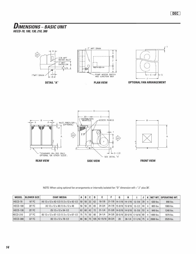
DIMENSIONS – BASIC UNITHECD-70, 100, 130, 210, 300
DETAIL “A” PLAN VIEW OPTIONAL FAN ARRANGEMENT
SIDE VIEWREAR VIEW
MODEL
HECD-70
HECD-100
HECD-130
HECD-210
HECD-300
BLOWER SIZE
18" FC
20" FC
25" FC
27" FC
33" FC
NOTE: When using optional fan arrangements or internally isolated fan “D” dimension will = “J” plus 30".
EVAP. MEDIA
(4) 12 x 12 x 42-1/2 (1) 2 x 12 x 42-1/2
(4) 12 x 12 x 48 (1) 8 x 12 x 48
(5) 12 x 12 x 54-1/2
(6) 12 x 12 x 67-1/2 (1) 3 x 12 x 67-1/2
(8) 12 x 12 x 78-1/2
A
50
56
62
75
86
B
50
56
60
75
96
C
32
35
42
50
75
D
62
65
72
80
105
J
39
44
53
60
75
NET WT.
630 lbs.
805 lbs.
949 lbs.
1489 lbs.
2008 lbs.
OPERATING WT.
890 lbs.
1069 lbs.
1240 lbs.
1879 lbs.
2529 lbs.
K
4
4
4
4
4
E
18-7/8
24-3/4
31-1/4
34-1/4
42-15/16
F
21-7/8
24-7/8
31-3/8
34-3/8
39-3/4
G
14-1/16
15-9/16
14-5/16
20-5/16
20
H
14-1/16
15-9/16
14-5/16
20-5/16
36-1/4
I
12-7/8
13-1/2
15-7/8
17-9/16
17-1/16
FRONT VIEW
DEC
15
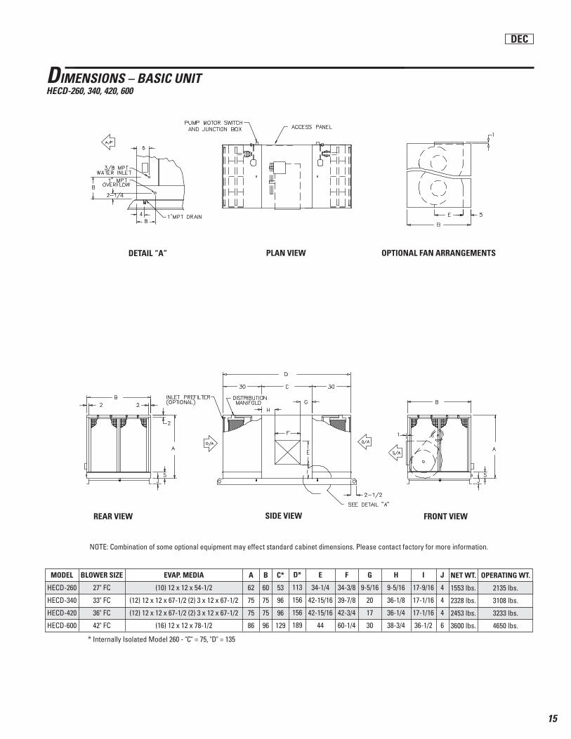
DIMENSIONS – BASIC UNITHECD-260, 340, 420, 600
NET WT.
1553 lbs.
2328 lbs.
2453 lbs.
3600 lbs.
SIDE VIEWREAR VIEW
PLAN VIEW OPTIONAL FAN ARRANGEMENTSDETAIL “A”
FRONT VIEW
MODEL
HECD-260
HECD-340
HECD-420
HECD-600
BLOWER SIZE
27" FC
33" FC
36" FC
42" FC
EVAP. MEDIA
(10) 12 x 12 x 54-1/2
(12) 12 x 12 x 67-1/2 (2) 3 x 12 x 67-1/2
(12) 12 x 12 x 67-1/2 (2) 3 x 12 x 67-1/2
(16) 12 x 12 x 78-1/2
A
62
75
75
86
B
60
75
75
96
C*
53
96
96
129
D*
113
156
156
189
E
34-1/4
42-15/16
42-15/16
44
F
34-3/8
39-7/8
42-3/4
60-1/4
G
9-5/16
20
17
30
H
9-5/16
36-1/8
36-1/4
38-3/4
I
17-9/16
17-1/16
17-1/16
36-1/2
OPERATING WT.
2135 lbs.
3108 lbs.
3233 lbs.
4650 lbs.
J
4
4
4
6
NOTE: Combination of some optional equipment may effect standard cabinet dimensions. Please contact factory for more information.
* Internally Isolated Model 260 - "C" = 75, "D" = 135
DEC
16
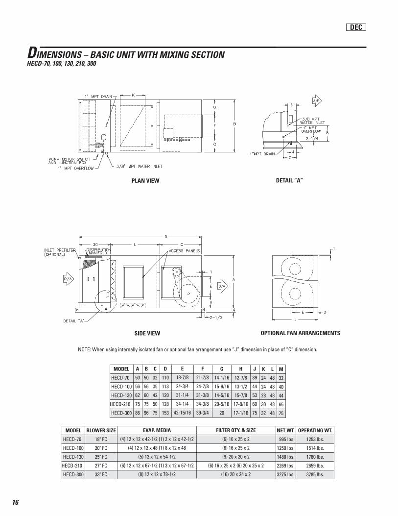
DIMENSIONS – BASIC UNIT WITH MIXING SECTIONHECD-70, 100, 130, 210, 300
SIDE VIEW OPTIONAL FAN ARRANGEMENTS
DETAIL “A”PLAN VIEW
NOTE: When using internally isolated fan or optional fan arrangement use “J” dimension in place of “C” dimension.
MODEL
HECD-70
HECD-100
HECD-130
HECD-210
HECD-300
BLOWER SIZE
18" FC
20" FC
25" FC
27" FC
33" FC
EVAP. MEDIA
(4) 12 x 12 x 42-1/2 (1) 2 x 12 x 42-1/2
(4) 12 x 12 x 48 (1) 8 x 12 x 48
(5) 12 x 12 x 54-1/2
(6) 12 x 12 x 67-1/2 (1) 3 x 12 x 67-1/2
(8) 12 x 12 x 78-1/2
FILTER QTY. & SIZE
(6) 16 x 25 x 2
(6) 16 x 25 x 2
(9) 20 x 20 x 2
(6) 16 x 25 x 2 (6) 20 x 25 x 2
(16) 20 x 24 x 2
NET WT.
995 lbs.
1250 lbs.
1488 lbs.
2269 lbs.
3275 lbs.
OPERATING WT.
1253 lbs.
1514 lbs.
1780 lbs.
2659 lbs.
3785 lbs.
MODEL
HECD-70
HECD-100
HECD-130
HECD-210
HECD-300
A
50
56
62
75
86
B
50
56
60
75
96
C
32
35
42
50
75
D
110
113
120
128
153
E
18-7/8
24-3/4
31-1/4
34-1/4
42-15/16
K
24
24
28
30
32
H
12-7/8
13-1/2
15-7/8
17-9/16
17-1/16
F
21-7/8
24-7/8
31-3/8
34-3/8
39-3/4
J
39
44
53
60
75
G
14-1/16
15-9/16
14-5/16
20-5/16
20
L
48
48
48
48
48
M
32
40
44
65
75
DEC

17
DIMENSIONS – BASIC UNIT WITH MIXING SECTIONHECD-260, 340, 420, 600
NOTE: When using internally isolated fan on 260 size only “C” dimension = 75" & “D” dimension = 219".
PLAN VIEW
DETAIL “A”
SIDE VIEW
MODEL
HECD-260
HECD-340
HECD-420
HECD-600
A
62
75
75
86
B
60
75
75
96
C
53
96
96
129
D
209
252
252
285
K
28
30
30
32
J
48
48
48
48
E
34-1/4
42-15/16
42-15/16
44
H
17-9/16
17-1/16
17-1/16
36-1/2
F
34-3/8
39-7/8
42-3/4
60-1/4
G
9-5/16
20
17
30
L
44
65
65
75
MODEL
HECD-260
HECD-340
HECD-420
HECD-600
BLOWER SIZE
27" FC
33" FC
36" FC
42" FC
FILTER QTY. & SIZE
(18) 20 x 20 x 2
(12) 16 x 25 x 2 (12) 20 x 25 x 2
(12) 16 x 25 x 2 (12) 20 x 25 x 2
(32) 20 x 25 x 2
EVAP. MEDIA
(10) 12 x 12 x 54-1/2
(12) 12 x 12 x 67-1/2 (2) 3 x 12 x 67-1/2
(12) 12 x 12 x 67-1/2 (2) 3 x 12 x 67-1/2
(16) 12 x 12 x 78-1/2
NET WT.
2650 lbs.
4040 lbs.
4215 lbs.
6100 lbs.
OPERATING WT.
3245 lbs.
4840 lbs.
5015 lbs.
7175 lbs.
DEC

18
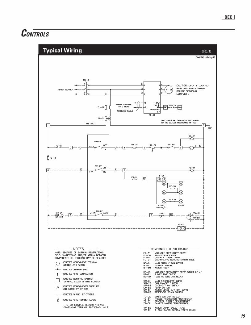
CONTROLS
-
+
Typical Wiring
DEC
C000741
19
-
+
CONTROLS
Typical Wiring
DEC
C000742

20
3.0 BLOWER SECTION
3.1 The blower section shall include a fan of the centrifugal type and be complete with motor and drive equipment. The fan shall be tested in accordance with standards set forth in Standard 210 of AMCA (Air Movement and Control Association). All air ratings are based on delivery against the external static pressure specifi ed with HECD system operating. Fan wheels shall have two (2) bearings, one mounted on each side of the wheel. Bearings shall be self-aligning, pillow block, ball bearing type with screw-in grease zerk fi ttings for relubrication. Fan shaft shall be ground and polished with key seats and keys for mounting wheel and fan pulley. Fan shall be connected to motor by means of an approvedV-belt drive with grooved pulleys. Motor pulleys shall be the adjustable pitch diameter type through 71/2 HP. The motor shall be designed to suit the characteristics of the available electric service. Motor shall be mounted on a base with adjusting slots which will permit easy belt adjustment.
3.2 Blower wheels shall be the centrifugal center hub type with multiple forward curved blades and double intake.
3.3 Blower scroll housing to be welded construction. When the fan motor is located above the blower housing, a frame shall support the adjustable motor base. In no case will the motor frame rest directly on the blower housing.
3.4 Standard unit construction to have top horizontal discharge from front of cabinet, with bottom horizontal, top vertical, or bottom vertical discharge available upon request.
3.5 Blower cabinet to be fabricated from galvanized steel. A removable panel permitting access to blower motor and drive shall be provided. Access panel is to be a minimum of 16" wide by 29" high and shall include two stainless steel retainers, handle and weatherproof gasket. Blower cabinet to be rigidly constructed, corrosion-resistant, and have a primer/enamel exterior fi nish.
TYPICAL SPECIFICATIONS
1.0 The evaporative cooling unit shall be weatherproof and self-contained. It consists of component parts as listed in the following paragraphs. Units shall be Turbocell as sold by Alton located in Dallas, Texas or approved equal.
2.0 HECD EVAPORATIVE SECTION
2.1 The HECD evaporative cooling section shall contain the HECD water system, 12" deep cell cooling media, fl oat valve, overfl ow, and drain connections. Evaporative module to be built separately from the blower section, and no water is to fl ow into the blower compartment at any time. Evaporative and blower sections are to be fi rmly attached. Cabinet shall be fabricated from 304 stainless steel. The cooling media shall be easily removable through a full size access panel located on the side of the casing. The side access panel shall also permit easy access to the pump, fl oat, water regulating and bleed-off valves.
2.2 Turbodek cooling media shall be 12" deep fl uted Fiberdek, high effi ciency evaporative media, impregnated with insoluble anti-rot chemicals. Maximum air velocity without water carryover is approximately 700 FPM.
2.3 HECD water system shall produce a fi ne spray action which uniformly saturates the 12" deep Fiberdek media. HECD system to include a submersible pump with U.L. listed, hermetically sealed, dielectric oil-fi lled motor and Buna-N seal. Horsepower rating of the pump shall not be less than 1/6 HP. Pump to be centrifugal type with suction strainer to prevent the intake of solid matter. Pump assembly shall discharge into a distribution manifold fabricated from heavy-duty PVC pipe with metered orifi ces. A water regulating valve shall be installed in the distribution manifold and will permit fi eld adjustment of water fl ow over the media. A manual pet-cock metering valve shall be installed in the distribution manifold allowing continuous bleed-off, thus minimizing the build-up of minerals and salts. The HECD water system assembly shall be available for 115 or 230 volt single phase operation.
2.4 An adjustable brass fl oat valve shall maintain a constant water level in the HECD tank.
2.5 The HECD evaporative cooling unit shall have a minimum saturation effectiveness of 88 percent at 700 FPM. Saturating effectiveness is defi ned as:
T1 - T2 SE = —— x 100 T1 - T3
Where: T1 = Outside air, dry bulb temperature, °F. T2 = Leaving air, dry bulb temperature, °F. T3 = Outside air, wet bulb temperature, °F.
MEDIA SPECIFICATIONS CONDITION FIBERDEK maximum water temp. 165°F maximum air temp. 300°F ph range 5-10 dry weight 4.5 lb/ft3
wet weight 9.0 lb/ft3
operating weight 11.4 lb/ft3
water fl ow rate (gpm/sq. ft.) 1.5
DEC

21
ASC – X – 1 A 0 1 – X X
Aztec Sensible Cooling® Equipment Heating Options: Nominal Face Area of 00 - No Heating Options Evaporative Section Media IF - Indirect Fired Furnace Section (Square Feet) HW - Hot Water Coil SC - Steam Coil Number of Stages of Evaporative Cooling: ER - Electric Resistance Coil One Stage -1 Two Stage -2 Supply Air Fan Provided - 1 Aztec Series Designation: Evaporative Cooling Section Options: “A” Series - A Indirect (Dry) - 0 Indirect/Direct - 1
AZTEC ASC MODEL DESIGNATION
IDEC

22
ASC FEATURES
INDIRECT UNITS:
• Direct drive centrifugal, backward airfoil, SWSI plenum type blower(s) rated in accordance with AMCA Standard 211 and bearing the AMCA seal.
• U.L. Listed three phase ODP supply fan motor(s)
• Variable frequency drive for supply air blower motor(s).
• Internal seismic-rated blower/motor isolation with fl exible ducting between blower(s) and unit casing.
• Stainless steel integral cooling tower with submersible pump(s).
• 6 row, aluminum fi n/copper tube indirect cooling coil section
• PVC plumbing
• Adjustable sump water bleed-off valve assembly in cooling tower section
• Low sump water level shut-off switch in cooling tower section
• Automatic fi ll and drain system
• Cabinet constructed of galvanized steel with corrosion-resistant enamel fi nish
• Insulated cabinet
• Formed galvanized steel channel base and intermediate equipment supports. Suitable for slab or curb mounting.
• Supply air, front access, nominal 2" MERV 8 fi lters.
• Hinged, double wall, insulated access door(s).
• Weather resistant, outside air intake louvers and birdscreen. One side hinged for fi lter access.
• Integral control box.
• DDC control system
• Listed by ETL Testing Laboratories.
INDIRECT/DIRECT UNITS:
• 12" deep Fiberdek media meeting UL 900 Class 2 rating
• Stainless steel direct evaporative section
• Adjustable sump water bleed-off valve assembly in cooling tower section
• Low sump water level shut-off switch in cooling tower section
• Automatic fi ll and drain system
• U.L. listed, single phase submersible pump
EQUIPMENT OPTIONS
• Double wall and roof cabinet construction
• TEFC Fan Motor(s)
• Mixing section with return air and outside air dampers
• 12" or 18" high full perimeter roof curb
• Direct drive centrifugal, backward airfoil, SWSI plenum type fan arrays
• MERV 11 and MERV 14 supply air fi lters
• Direct expansion or chilled water cooling coil
• Variable frequency drive on cooling tower fan
• Smoke detector
• Firestat
• Copper plumbing
• UL labeled control panel
IDEC
23
1500 2000 2500 2500 3000 3500 3500 4250 5000 5000 6250 7500 7500 8750 10,000 10,000 11,250 12,500 12,500 13,750 15,000 15,000 17,500 20,000 20,000 22,500 25,000 25,000 27,500 30,000 30,000 33,750 37,500
270360450281338394315383450333417500346404462353397441400440480327382436400450500381419457384432480
Indirect Cooling
CoilΔP
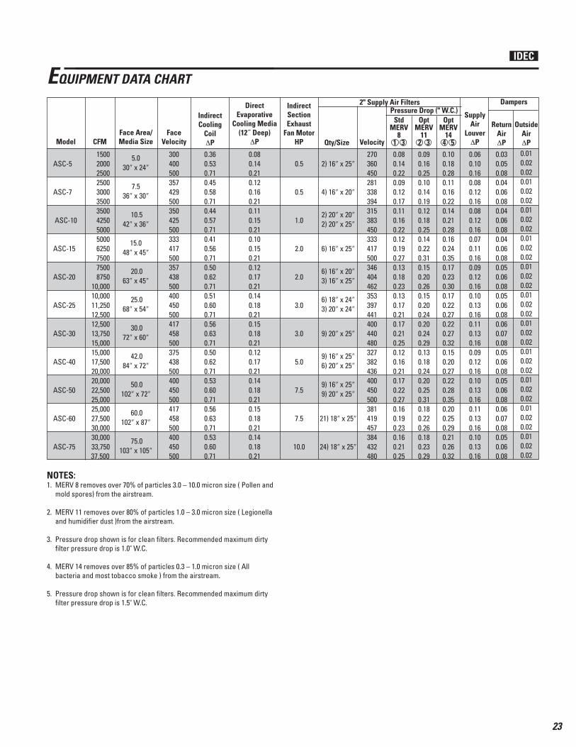
EQUIPMENT DATA CHART
Pressure Drop (" W.C.)2" Supply Air Filters DampersIndirect
SectionExhaust
Fan Motor HP
Direct Evaporative
Cooling Media (12˝ Deep)
ΔPFace Area/Media Size
FaceVelocity
OutsideAirΔP
ReturnAirΔP
SupplyAir
LouverΔPModel CFM Qty/Size Velocity
Opt MERV
14 4 5
Opt MERV
112 3
Std MERV
8 1 3
5.030″ x 24″
7.536″ x 30″
10.542″ x 36″
15.048″ x 45″
20.063″ x 45″
25.068″ x 54″
30.072″ x 60″
42.084″ x 72″
50.0102″ x 72″
60.0102″ x 87″
75.0103″ x 105″
300400500357429500350425500333417500357438500400450500417458500375438500400450500417458500400450500
0.360.530.710.450.580.710.440.570.710.410.560.710.500.620.710.510.600.710.560.630.710.500.620.710.530.600.710.560.630.710.530.600.71
0.080.140.210.120.160.210.110.150.210.100.150.210.120.170.210.140.180.210.150.180.210.120.170.210.140.180.210.150.180.210.140.180.21
0.5
0.5
1.0
2.0
2.0
3.0
3.0
5.0
7.5
7.5
10.0
2) 16″ x 25″
4) 16″ x 20″
2) 20″ x 20″2) 20″ x 25″
6) 16″ x 25″
6) 16″ x 20″3) 16″ x 25″
6) 18″ x 24″3) 20″ x 24″
9) 20″ x 25″
9) 16″ x 25″6) 20″ x 25″
9) 16″ x 25″9) 20″ x 25″
21) 18″ x 25″
24) 18″ x 25″
0.060.100.160.080.120.160.080.120.160.070.110.160.090.120.160.100.130.160.110.130.160.090.120.160.100.130.160.110.130.160.100.130.16
0.100.180.280.110.160.220.140.210.280.160.240.350.170.230.300.170.220.270.220.270.320.150.200.270.220.280.350.200.250.290.210.260.32
0.090.160.250.100.140.190.120.180.250.140.220.310.150.200.260.150.200.240.200.240.290.130.180.240.200.250.310.180.220.260.180.230.29
0.080.140.220.090.120.170.110.160.220.120.190.270.130.180.230.130.170.210.170.210.250.120.160.210.170.220.270.160.190.230.160.210.25
0.010.020.020.010.020.020.010.020.020.010.020.020.010.020.020.010.020.020.010.020.020.010.020.020.010.020.020.010.020.020.010.020.02
0.030.050.080.040.060.080.040.060.080.040.060.080.050.060.080.050.060.080.060.070.080.050.060.080.050.060.080.060.070.080.050.060.08
ASC-5
ASC-7
ASC-10
ASC-15
ASC-20
ASC-25
ASC-30
ASC-40
ASC-50
ASC-60
ASC-75
NOTES:1. MERV 8 removes over 70% of particles 3.0 – 10.0 micron size ( Pollen and
mold spores) from the airstream.
2. MERV 11 removes over 80% of particles 1.0 – 3.0 micron size ( Legionella and humidifi er dust )from the airstream.
3. Pressure drop shown is for clean fi lters. Recommended maximum dirty fi lter pressure drop is 1.0" W.C.
4. MERV 14 removes over 85% of particles 0.3 – 1.0 micron size ( All bacteria and most tobacco smoke ) from the airstream.
5. Pressure drop shown is for clean fi lters. Recommended maximum dirty fi lter pressure drop is 1.5" W.C.
IDEC
24
1,5002,0002,5002,5003,0003,5003,5004,2505,0005,0006,2507,5007,5008,750
10,00010,00011,25012,50012,50013,75015,00015,00017,50020,00020,00022,50025,00025,00027,50030,00030,00033,75037,500
FEGFan
RPMFan
RPMFan
RPMFan
RPM
TSP - System Total Static Pressure (Inches W.C.)
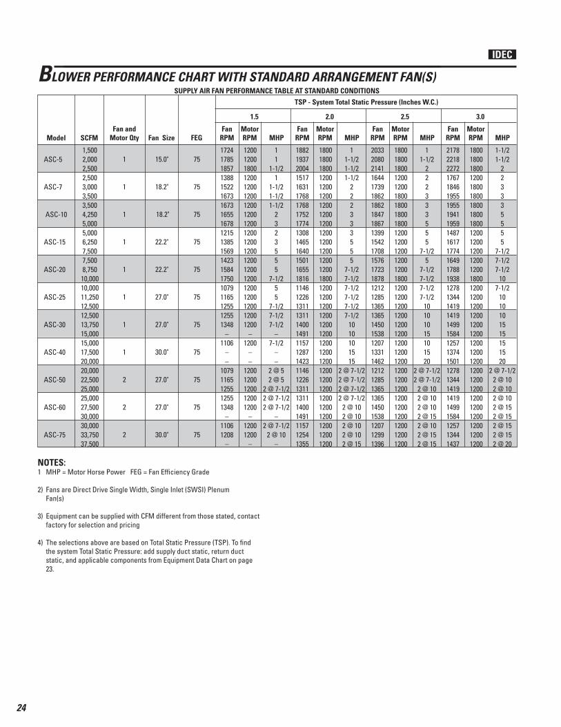
SUPPLY AIR FAN PERFORMANCE TABLE AT STANDARD CONDITIONS
MotorRPM
MotorRPM
MotorRPM
MotorRPMMHP MHP MHP MHP
BLOWER PERFORMANCE CHART WITH STANDARD ARRANGEMENT FAN(S)
Fan and Motor Qty Fan SizeModel SCFM
1
1
1
1
1
1
1
1
2
2
2
15.0"
18.2"
18.2"
22.2"
22.2"
27.0"
27.0"
30.0"
27.0"
27.0"
30.0"
75
75
75
75
75
75
75
75
75
75
75
17241785185713881522167316731655167812151385156914231584175010791165125512551348
–1106
––
10791165125512551348
–11061208
–
203320802141164417391862186218471867139915421708157617231878121212851365136514501538120713311462121212851365136514501538120712991396
188219372004151716311768176817521774130814651640150116551816114612261311131114001491115712871423114612261311131114001491115712541355
217822182272176718461955195519411959148716171774164917881938127813441419141914991584125713741501127813441419141914991584125713441437
12001200180012001200120012001200120012001200120012001200120012001200120012001200
–1200
––
12001200120012001200
–12001200
–
180018001800120012001800180018001800120012001200120012001800120012001200120012001200120012001200120012001200120012001200120012001200
180018001800120012001200120012001200120012001200120012001800120012001200120012001200120012001200120012001200120012001200120012001200
180018001800120018001800180018001800120012001200120012001800120012001200120012001200120012001200120012001200120012001200120012001200
11
1-1/21
1-1/21-1/21-1/2
2323555
7-1/255
7-1/27-1/27-1/2
–7-1/2
––
2 @ 52 @ 5
2 @ 7-1/22 @ 7-1/22 @ 7-1/2
–2 @ 7-1/2
2 @ 10–
11-1/2
222333555
7-1/25
7-1/27-1/27-1/27-1/2
10101015101520
2 @ 7-1/22 @ 7-1/2
2 @ 102 @ 102 @ 102 @ 152 @ 102 @ 152 @ 15
11-1/21-1/21-1/2
222333555
7-1/27-1/27-1/27-1/27-1/27-1/2
1010101515
2 @ 7-1/22 @ 7-1/22 @ 7-1/22 @ 7-1/2
2 @ 102 @ 102 @ 102 @ 102 @ 15
1-1/21-1/2
223335555
7-1/27-1/27-1/2
107-1/2
1010101515151520
2 @ 7-1/22 @ 102 @ 102 @ 102 @ 152 @ 152 @ 152 @ 152 @ 20
ASC-5
ASC-7
ASC-10
ASC-15
ASC-20
ASC-25
ASC-30
ASC-40
ASC-50
ASC-60
ASC-75
NOTES:1 MHP = Motor Horse Power FEG = Fan Effi ciency Grade
2) Fans are Direct Drive Single Width, Single Inlet (SWSI) Plenum Fan(s)
3) Equipment can be supplied with CFM different from those stated, contact factory for selection and pricing
4) The selections above are based on Total Static Pressure (TSP). To fi nd the system Total Static Pressure: add supply duct static, return duct static, and applicable components from Equipment Data Chart on page 23.
1.5 2.0 2.5 3.0
IDEC

25
1,5002,0002,5002,5003,0003,5003,5004,2505,0005,0006,2507,5007,5008,750
10,00010,00011,25012,50012,50013,75015,00015,00017,50020,00020,00022,50025,00025,00027,50030,00030,00033,75037,500
FEGFan
RPMFan
RPMFan
RPMFan
RPM
TSP - System Total Static Pressure (Inches W.C.)
SUPPLY AIR FAN PERFORMANCE TABLE AT STANDARD CONDITIONS
MotorRPM
MotorRPM
MotorRPM
MotorRPMMHP MHP MHP MHP
BLOWER PERFORMANCE CHART WITH STANDARD ARRANGEMENT FAN(S)
Fan and Motor Qty Fan SizeModel SCFM
1
1
1
1
1
1
1
1
2
2
2
15.0"
18.2"
18.2"
22.2"
22.2"
27.0"
27.0"
30.0"
27.0"
27.0"
30.0"
75
75
75
75
75
75
75
75
75
75
75
231823522399188719512047204720342051157416901838171918511996134314031472147215481629130614171539134314031472147215481629130613881477
258726092644211521572229222922192232174418331962185819742108147315191577157716451718140515021614147315191577157716451718140514761556
245424822523200320552138213821272142166017621901178919132052140914611525152515961674135614591576140914611525152515961674135614321517
271527332762
–22572319231923102322182619032023192620342162153815781630163016931763145415441651153815781630163016931763145415201596
180018001800180018001800180018001800120012001800120018001800120012001200120012001200120012001200120012001200120012001200120012001200
180018001800180018001800180018001800120018001800180018001800120012001200120012001200120012001200120012001200120012001200120012001200
180018001800180018001800180018001800120012001800120018001800120012001200120012001200120012001200120012001200120012001200120012001200
180018001800
–18001800180018001800180018001800180018001800120012001200120012001200120012001200120012001200120012001200120012001200
1-1/2233355555
7-1/27-1/27-1/2
1010101015151515152020
2 @102 @102 @152 @ 152 @152 @ 152 @ 152 @ 152 @ 20
23335555
7-1/27-1/27-1/2
10101015151515152020202025
2 @ 152 @ 152 @ 152 @ 152 @ 202 @ 202 @ 202 @ 202 @ 25
233335555
7-1/27-1/27-1/27-1/2
1015101515151520152025
2 @ 102 @ 152 @ 152 @ 152 @ 152 @ 202 @ 152 @ 202 @ 20
335–555
7-1/27-1/27-1/2
1010101515151520202020202530
2 @ 152 @ 152 @ 202 @ 202 @ 202 @ 202 @ 202 @ 252 @ 25
ASC-5
ASC-7
ASC-10
ASC-15
ASC-20
ASC-25
ASC-30
ASC-40
ASC-50
ASC-60
ASC-75
NOTES:1. MHP = Motor Horse Power FEG = Fan Effi ciency Grade
2. Fans are Direct Drive Single Width, Single Inlet (SWSI) Plenum Fan(s)
3. Equipment can be supplied with CFM different from those stated, contact factory for selection and pricing
4. The selections above are based on Total Static Pressure. To fi nd the system Total Static Pressure: add supply duct static, return duct static, and applicable components from Equipment Data Chart on page 23.
3.5 4.0 4.5 5.0
IDEC

26
1,5002,0002,5002,5003,0003,5003,5004,2505,0005,0006,2507,5007,5008,750
10,00010,00011,25012,50012,50013,75015,00015,00017,50020,00020,00022,50025,00025,00027,50030,00030,00033,75037,500
FEGFan
RPMFan
RPMFan
RPMFan
RPM
TSP - System Total Static Pressure (Inches W.C.)
SUPPLY AIR FAN PERFORMANCE TABLE AT STANDARD CONDITIONS
MotorRPM
MotorRPM
MotorRPM
MotorRPMMHP MHP MHP MHP
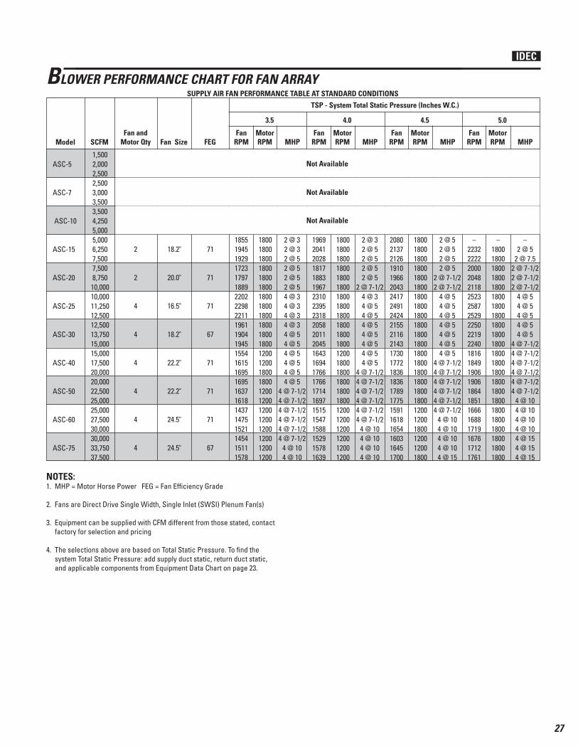
BLOWER PERFORMANCE CHART FOR FAN ARRAY
Fan and Motor Qty Fan SizeModel SCFM
1
1
1
2
2
4
4
4
4
4
4
15.0"
18.2"
18.2"
18.2"
20.0"
16.5"
18.2"
22.2"
22.2"
24.5"
24.5"
75
75
75
71
71
71
67
71
71
71
67
172417851857138815221673167316551678137315431518131514261545176118981774155214571527118012831392139213141287111511771243114612321322
203320802141164417391862186218471867161917481727152616201725198421021996176116851741137114541549154914801457127913291385130213741453
188219372004151716311768176817521774149716471624142315261637187420021886165915731636127713701472147213981373119812541315122513041388
217822182272176718461955195519411959173818471829162617101808209422002104186217961843146415351623162315591538135814031454137814431516
120012001800120012001200120012001200120012001200120012001200180018001800120012001200120012001200120012001200120012001200120012001200
180018001800120012001800180018001800120018001800120012001800180018001800180018001800120012001200120012001200120012001200120012001200
180018001800120012001200120012001200120012001200120012001200180018001800180012001200120012001200120012001200120012001200120012001200
180018001800120018001800180018001800180018001800120018001800180018001800180018001800120012001200120012001200120012001200120012001200
11
1-1/21
1-1/21-1/21-1/2
23
2 @ 1-1/22 @ 32 @ 32 @ 32 @ 32 @ 34 @ 34 @ 34 @ 34 @ 34 @ 34 @ 34 @ 34 @ 34 @ 34 @ 34 @ 34 @ 34 @ 34 @ 54 @ 54 @ 54 @ 54 @ 5
11-1/2
2223335
2 @ 32 @ 32 @ 32 @ 32 @ 32 @ 54 @ 34 @ 34 @ 34 @ 34 @ 34 @ 34 @ 34 @ 34 @ 54 @ 54 @ 54 @ 54 @ 54 @ 54 @ 54 @ 5
4 @ 7-1/24 @ 7-1/2
11-1/21-1/21-1/2
22233
2 @ 32 @ 32 @ 32 @ 32 @ 32 @ 34 @ 34 @ 34 @ 34 @ 34 @ 34 @ 34 @ 34 @ 34 @ 34 @ 34 @ 54 @ 54 @ 54 @ 54 @ 54 @ 54 @ 5
4 @ 7-1/2
1-1/21-1/2
2233355
2 @ 32 @ 32 @ 32 @ 32 @ 52 @ 54 @ 34 @ 34 @ 34 @ 34 @ 34 @ 54 @ 34 @ 54 @ 54 @ 54 @ 54 @ 54 @ 5
4 @ 7-1/24 @ 7-1/24 @ 7-1/24 @ 7-1/2
4 @ 10
ASC-5
ASC-7
ASC-10
ASC-15
ASC-20
ASC-25
ASC-30
ASC-40
ASC-50
ASC-60
ASC-75
NOTES:1. MHP = Motor Horse Power FEG = Fan Effi ciency Grade
2. Fans are Direct Drive Single Width, Single Inlet (SWSI) Plenum Fan(s)
3. Equipment can be supplied with CFM different from those stated, contact factory for selection and pricing
4. The selections above are based on Total Static Pressure (TSP). To fi nd the system Total Static Pressure: add supply duct static, return duct static, and applicable components from Equipment Data Chart on page 23.
1.5 2.0 2.5 3.0
Not Available
Not Available
Not Available
IDEC
27
1,5002,0002,5002,5003,0003,5003,5004,2505,0005,0006,2507,5007,5008,750
10,00010,00011,25012,50012,50013,75015,00015,00017,50020,00020,00022,50025,00025,00027,50030,00030,00033,75037,500
FEGFan
RPMFan
RPMFan
RPMFan
RPM
TSP - System Total Static Pressure (Inches W.C.)
SUPPLY AIR FAN PERFORMANCE TABLE AT STANDARD CONDITIONS
MotorRPM
MotorRPM
MotorRPM
MotorRPMMHP MHP MHP MHP
BLOWER PERFORMANCE CHART FOR FAN ARRAY
Fan and Motor Qty Fan SizeModel SCFM
1
1
1
2
2
4
4
4
4
4
4
15.0"
18.2"
18.2"
18.2"
20.0"
16.5"
18.2"
22.2"
22.2"
24.5"
24.5"
75
75
75
71
71
71
67
71
71
71
67
172417851857138815221673167316551678185519451929172317971889220222982211196119041945155416151695169516371618143714751521145415111578
203320802141164417391862186218471867208021372126191019662043241724912424215521162143173017721836183617891775159116181654160316451700
188219372004151716311768176817521774196920412028181718831967231023952318205820112045164316941766176617141697151515471588152915781639
217822182272176718461955195519411959
–22322222200020482118252325872529225022192240181618491906190618641851166616881719167617121761
120012001800120012001200120012001200180018001800180018001800180018001800180018001800120012001800180012001200120012001200120012001200
180018001800120012001800180018001800180018001800180018001800180018001800180018001800180018001800180018001800120012001800120012001800
180018001800120012001200120012001200180018001800180018001800180018001800180018001800120018001800180018001800120012001200120012001200
180018001800120018001800180018001800
–18001800180018001800180018001800180018001800180018001800180018001800180018001800180018001800
11
1-1/21
1-1/21-1/21-1/2
23
2 @ 32 @ 32 @ 52 @ 52 @ 52 @ 54 @ 34 @ 34 @ 34 @ 34 @ 54 @ 54 @ 54 @ 54 @ 54 @ 5
4 @ 7-1/24 @ 7-1/24 @ 7-1/24 @ 7-1/24 @ 7-1/24 @ 7-1/2
4 @ 104 @ 10
11-1/2
2223335
2 @ 52 @ 52 @ 52 @ 5
2 @ 7-1/22 @ 7-1/2
4 @ 54 @ 54 @ 54 @ 54 @ 54 @ 54 @ 5
4 @ 7-1/24 @ 7-1/24 @ 7-1/24 @ 7-1/24 @ 7-1/24 @ 7-1/2
4 @ 104 @ 104 @ 104 @ 104 @ 15
11-1/21-1/21-1/2
22233
2 @ 32 @ 52 @ 52 @ 52 @ 5
2 @ 7-1/24 @ 34 @ 54 @ 54 @ 54 @ 54 @ 54 @ 54 @ 5
4 @ 7-1/24 @ 7-1/24 @ 7-1/24 @ 7-1/24 @ 7-1/24 @ 7-1/2
4 @ 104 @ 104 @ 104 @ 10
1-1/21-1/2
2233355–
2 @ 52 @ 7.5
2 @ 7-1/22 @ 7-1/22 @ 7-1/2
4 @ 54 @ 54 @ 54 @ 54 @ 5
4 @ 7-1/24 @ 7-1/24 @ 7-1/24 @ 7-1/24 @ 7-1/24 @ 7-1/2
4 @ 104 @ 104 @ 104 @ 104 @ 154 @ 154 @ 15
ASC-5
ASC-7
ASC-10
ASC-15
ASC-20
ASC-25
ASC-30
ASC-40
ASC-50
ASC-60
ASC-75
NOTES:1. MHP = Motor Horse Power FEG = Fan Effi ciency Grade
2. Fans are Direct Drive Single Width, Single Inlet (SWSI) Plenum Fan(s)
3. Equipment can be supplied with CFM different from those stated, contact factory for selection and pricing
4. The selections above are based on Total Static Pressure. To fi nd the system Total Static Pressure: add supply duct static, return duct static, and applicable components from Equipment Data Chart on page 23.
3.5 4.0 4.5 5.0
Not Available
Not Available
Not Available
IDEC

28
1,5002,0002,5002,5003,0003,5003,5004,2505,0005,0006,2507,5007,5008,750
10,00010,00011,25012,50012,50013,75015,00015,00017,50020,00020,00022,50025,00025,00027,50030,00030,00033,75037,500
FEGFan
RPMFan
RPMFan
RPMFan
RPM
TSP - System Total Static Pressure (Inches W.C.)
SUPPLY AIR FAN PERFORMANCE TABLE AT STANDARD CONDITIONS
MotorRPM
MotorRPM
MotorRPM
MotorRPMMHP MHP MHP MHP
BLOWER PERFORMANCE CHART FOR FAN ARRAY WITH 100% REDUNDANCY
Fan and Motor Qty Fan SizeModel SCFM
1
1
1
2
2
4
4
4
4
4
4
15.0"
18.2"
18.2"
18.2"
20.0"
16.5"
18.2"
22.2"
22.2"
24.5"
24.5"
75
75
75
71
71
71
67
71
71
71
67
172417851857138815221673167316551678137315431518131514261545176118981774155214571527118012831392139213141287111511771243114612321322
203320802141164417391862186218471867161917481727152616201725198421021996176116851741137114541549154914801457127913291385130213741453
188219372004151716311768176817521774149716471624142315261637187420021886165915731636127713701472147213981373119812541315122513041388
217822182272176718461955195519411959173818471829162617101808209422002104186217961843146415351623162315591538135814031454137814431516
120012001800120012001200120012001200120012001200120012001200180018001800120012001200120012001200120012001200120012001200120012001200
180018001800120012001800180018001800120018001800120012001800180018001800180018001800120012001200120012001200120012001200120012001200
180018001800120012001200120012001200120012001200120012001200180018001800180012001200120012001200120012001200120012001200120012001200
180018001800120018001800180018001800180018001800120018001800180018001800180018001800120012001200120012001200120012001200120012001200
11
1-1/21
1-1/21-1/21-1/2
23
2 @ 32 @ 5
2 @ 7-1/22 @ 5
2 @ 7-1/22 @ 104 @ 34 @ 34 @ 34 @ 34 @ 34 @ 34 @ 34 @ 34 @ 54 @ 54 @ 54 @ 54 @ 54 @ 5
4 @ 7-1/24 @ 7-1/24 @ 7-1/2
4 @ 10
11-1/2
2223335
2 @ 52 @ 7-1/22 @ 7-1/22 @ 7-1/2
2 @ 102 @ 154 @ 34 @ 34 @ 54 @ 54 @ 54 @ 54 @ 54 @ 54 @ 54 @ 5
4 @ 7-1/24 @ 7-1/24 @ 7-1/24 @ 7-1/24 @ 7-1/24 @ 7-1/2
4 @ 104 @ 15
11-1/21-1/21-1/2
22233
2 @ 52 @ 7-1/22 @ 7-1/22 @ 7-1/22 @ 7-1/2
2 @ 104 @ 34 @ 34 @ 34 @ 34 @ 34 @ 54 @ 34 @ 54 @ 54 @ 54 @ 54 @ 54 @ 5
4 @ 7-1/24 @ 7-1/24 @ 7-1/24 @ 7-1/2
4 @ 10
1-1/21-1/2
2233355
2 @ 52 @ 7-1/2
2 @ 102 @ 7-1/2
2 @ 102 @ 154 @ 34 @ 54 @ 54 @ 54 @ 54 @ 54 @ 54 @ 5
4 @ 7-1/24 @ 7-1/24 @ 7-1/24 @ 7-1/24 @ 7-1/24 @ 7-1/2
4 @ 104 @ 104 @ 104 @ 15
ASC-5
ASC-7
ASC-10
ASC-15
ASC-20
ASC-25
ASC-30
ASC-40
ASC-50
ASC-60
ASC-75
NOTES:1. MHP = Motor Horse Power FEG = Fan Effi ciency Grade
2. Fans are Direct Drive Single Width, Single Inlet (SWSI) Plenum Fan(s)
3. Equipment can be supplied with CFM different from those stated, contact factory for selection and pricing
4. The selections above are based on Total Static Pressure (TSP). To fi nd the system Total Static Pressure: add supply duct static, return duct static, and applicable components from Equipment Data Chart on page 23.
1.5 2.0 2.5 3.0
Not Available
Not Available
Not Available
IDEC

29
1,5002,0002,5002,5003,0003,5003,5004,2505,0005,0006,2507,5007,5008,750
10,00010,00011,25012,50012,50013,75015,00015,00017,50020,00020,00022,50025,00025,00027,50030,00030,00033,75037,500
FEGFan
RPMFan
RPMFan
RPMFan
RPM
TSP - System Total Static Pressure (Inches W.C.)
SUPPLY AIR FAN PERFORMANCE TABLE AT STANDARD CONDITIONS
MotorRPM
MotorRPM
MotorRPM
MotorRPMMHP MHP MHP MHP
Fan and Motor Qty Fan SizeModel SCFM
1
1
1
2
2
4
4
4
4
4
4
15.0"
18.2"
18.2"
18.2"
20.0"
16.5"
18.2"
22.2"
22.2"
24.5"
24.5"
75
75
75
71
71
71
67
71
71
71
67
172417851857138815221673167316551678185519451929172317971889220222982211196119041945155416151695169516371618143714751521145415111578
203320802141164417391862186218471867208021372126191019662043241724912424215521162143173017721836183617891775159116181654160316451700
188219372004151716311768176817521774196920412028181718831967231023952318205820112045164316941766176617141697151515471588152915781639
217822182272176718461955195519411959NA
22322222200020482118252325872529225022192240181618491906190618641851166616881719167617121761
120012001800120012001200120012001200180018001800180018001800180018001800180018001800120012001800180012001200120012001200120012001200
180018001800120012001800180018001800180018001800180018001800180018001800180018001800180018001800180018001800120012001800120012001800
180018001800120012001200120012001200180018001800180018001800180018001800180018001800120018001800180018001800120012001200120012001200
180018001800120018001800180018001800NA
18001800180018001800180018001800180018001800180018001800180018001800180018001800180018001800
11
1-1/21
1-1/21-1/21-1/2
23
2 @ 7-1/22 @ 7-1/2
2 @ 102 @ 102 @ 102 @ 154 @ 54 @ 54 @ 54 @ 54 @ 54 @ 54 @ 5
4 @ 7-1/24 @ 7-1/24 @ 7-1/24 @ 7-1/2
4 @ 104 @ 7-1/2
4 @ 104 @ 104 @ 104 @ 154 @ 15
11-1/2
2223335
2 @ 7-1/22 @ 102 @ 152 @ 102 @ 152 @ 154 @ 54 @ 54 @ 54 @ 5
4 @ 7-1/24 @ 7-1/24 @ 7-1/24 @ 7-1/2
4 @ 104 @ 104 @ 104 @ 104 @ 104 @ 154 @ 154 @ 154 @ 154 @ 20
11-1/21-1/21-1/2
22233
2 @ 7-1/22 @ 102 @ 102 @ 102 @ 152 @ 154 @ 54 @ 54 @ 54 @ 54 @ 5
4 @ 7-1/24 @ 5
4 @ 7-1/24 @ 7-1/24 @ 7-1/2
4 @ 104 @ 104 @ 104 @ 104 @ 154 @ 154 @ 154 @ 15
1-1/21-1/2
2233355
NA2 @ 102 @ 152 @ 152 @ 152 @ 204 @ 5
4 @ 7-1/24 @ 7-1/24 @ 7-1/24 @ 7-1/24 @ 7-1/24 @ 7-1/24 @ 7-1/2
4 @ 104 @ 104 @ 104 @ 154 @ 154 @ 154 @ 154 @ 154 @ 154 @ 20
ASC-5
ASC-7
ASC-10
ASC-15
ASC-20
ASC-25
ASC-30
ASC-40
ASC-50
ASC-60
ASC-75
NOTES:1. MHP = Motor Horse Power FEG = Fan Effi ciency Grade
2. Fans are Direct Drive Single Width, Single Inlet (SWSI) Plenum Fan(s)
3. Equipment can be supplied with CFM different from those stated, contact factory for selection and pricing
4. The selections above are based on Total Static Pressure. To fi nd the system Total Static Pressure: add supply duct static, return duct static, and applicable components from Equipment Data Chart on page 23.
3.5 4.0 4.5 5.0
Not Available
Not Available
Not Available
BLOWER PERFORMANCE CHART FOR FAN ARRAY WITH 100% REDUNDANCY
IDEC

30
1 2 4 1 2 4 1 2 4 1 2 4 200 V 3 Ph 2.6 5.2 10.4 4.8 9.6 19.2 6.9 13.8 27.6 7.8 15.6 31.2 208 V 3 Ph 2.5 5.0 10.0 4.6 9.2 18.4 6.6 13.2 26.4 7.5 15.0 30.0 230 V 3 Ph 2.0 4.0 8.0 4.2 8.4 16.8 6.0 12.0 24.0 6.8 13.6 27.2 460 V 3 Ph 1.0 2.0 4.0 2.1 4.2 8.4 3.0 6.0 12.0 3.4 6.8 13.6 575 V 3 Ph 0.8 1.6 3.2 1.7 3.4 6.8 2.4 4.8 9.6 2.7 5.4 10.8
1 2 4 1 2 4 1 2 4 1 2 4 200 V 3 Ph 11.0 22.0 44.0 17.5 35 70 25.3 50.6 101 32.2 64.40 129 208 V 3 Ph 10.6 21.2 42.4 16.7 33.4 66.8 24.2 48.4 96.8 30.8 61.60 123 230 V 3 Ph 9.6 19.2 38.4 15.3 30.6 61.2 22.0 44.0 88.0 28.8 57.60 115 460 V 3 Ph 4.8 9.6 19.2 7.6 15.2 30.4 11.0 22.0 44.0 14.4 28.80 57.6 575 V 3 Ph 3.9 7.8 15.6 6.1 12.2 24.4 9.0 18.0 36.0 11.5 23.00 46.0
1 2 4 1 2 4 1 2 4 1 2 4 200 V 3 Ph 48.3 96.6 193.2 62.1 124 248 78.2 156 313 92.0 184 368 208 V 3 Ph 46.2 92.4 184.8 59.4 119 238 74.8 150 299 88.0 176 352 230 V 3 Ph 42.0 84.0 168 54.0 108 216 68.0 136 272 80.0 160 320 460 V 3 Ph 21.0 42.0 84.0 27.0 54.0 108 34.0 68.0 136 40.0 80.0 160 575 V 3 Ph 17.0 34.0 68.0 22.0 44.0 88.0 27.0 54.0 108 32.0 64.0 128
200 V 3 Ph 208 V 3 Ph 230 V 3 Ph 460 V 3 Ph 575 V 3 Ph
NOTES 1) CF = Contact Factory2) Above motor amps are based on 2011 edition of NEC.3) Control circuit amps are based on standard controls.
Steps to Size Optional Disconnect Switch:1. Find the Indirect Section Exhaust Fan Motor HP from chart on page 23.2. Find amp draw for Indirect Section Exhaust Fan Motor HP from chart in Item A above.3. Find the blower motor HP required from charts on pages 24 - 29.4. Find amp draw for blower motor HP from chart in Item A above.5. Find amps for controls from chart in Item B above.6. Add amps from steps 2, 4 and 5, then multipy by 1.25.
14.614.012.76.4CF
4.33.5
9.69.28.44.2
12.512.010.95.44.3
12.512.010.95.44.3
B
Indirect Unit Size40 - 7515 - 305 - 10
CF
7.57.26.53.32.6
Controls
AMPS
10.09.68.7
Indirect/Direct Unit Size5 - 10 15 - 30 40 - 75
ITEM SOURCE
25 30
Motor Horsepower
Motor Horsepower15
Motor Qty Motor Qty Motor Qty5 7-1/2
BlowerMotor(s)A
Pump(s) and Control Circuit Amps
2Motor Qty
AMPS
AMPS
AMPS
Motor Qty3
Motor Qty Motor Qty Motor Qty Motor Qty20
Motor Horsepower
10
1/2Motor Qty
1 1-1/2Motor Qty Motor Qty
ASC AMP DRAW TABLE
IDEC
31
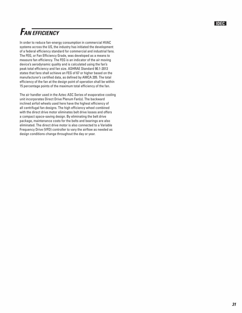
FAN EFFICIENCY
In order to reduce fan-energy consumption in commercial HVAC systems across the US, the industry has initiated the development of a federal effi ciency standard for commercial and industrial fans. The FEG, or Fan Effi ciency Grade, was developed as a means to measure fan effi ciency. The FEG is an indicator of the air moving device’s aerodynamic quality and is calculated using the fan’s peak total effi ciency and fan size. ASHRAE Standard 90.1-2013 states that fans shall achieve an FEG of 67 or higher based on the manufacturer’s certifi ed data, as defi ned by AMCA 205. The total effi ciency of the fan at the design point of operation shall be within 15 percentage points of the maximum total effi ciency of the fan.
The air handler used in the Aztec ASC Series of evaporative cooling unit incorporates Direct Drive Plenum Fan(s). The backward inclined airfoil wheels used here have the highest effi ciency of all centrifugal fan designs. The high effi ciency wheel combined with the direct drive motor eliminates belt drive losses and offers a compact space-saving design. By eliminating the belt drive package, maintenance costs for the belts and bearings are also eliminated. The direct drive motor is also connected to a Variable Frequency Drive (VFD) controller to vary the airfl ow as needed as design conditions change throughout the day or year.
IDEC
32
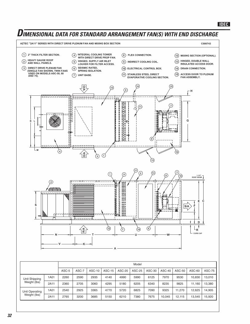
DIMENSIONAL DATA FOR STANDARD ARRANGEMENT FAN(S) WITH END DISCHARGE
IDEC
ASC-5 ASC-7 ASC-10 ASC-15 ASC-20 ASC-25 ASC-30 ASC-40 ASC-50 ASC-60 ASC-75
1A01 2260 2590 2935 4140 4990 5990 6125 7970 9530 10,830 13,010
2A11 2360 2705 3060 4295 5180 6205 6340 8235 9825 11,160 13,380
1A01 2540 2925 3365 4770 5720 6825 7090 9325 11,270 12,625 14,905
2A11 2765 3200 3685 5150 6210 7380 7675 10,045 12,115 13,545 15,920
Model
Unit ShippingWeight (lbs)
Unit OperatingWeight (lbs)
33
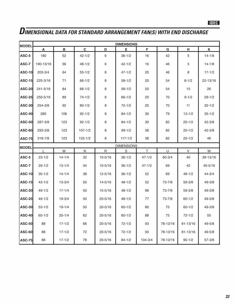
DIMENSIONAL DATA FOR STANDARD ARRANGEMENT FAN(S) WITH END DISCHARGE
ASC-5
ASC-7
ASC-10
ASC-15
ASC-20
ASC-25
ASC-30
ASC-40
ASC-50
ASC-60
ASC-75
ASC-5
ASC-7
ASC-10
ASC-15
ASC-20
ASC-25
ASC-30
ASC-40
ASC-50
ASC-60
ASC-75
17-1/4
19-3/4
19-1/4
20-1/4
17-1/2
17-1/2
17-1/2
L
23-1/2
29-1/2
35-1/2
43-1/2
49-1/2
49-1/2
53-1/2
65-1/2
88
88
88
93
93
104-3/4
S
36-1/2
36-1/2
36-1/2
48-1/2
48-1/2
48-1/2
60-1/2
60-1/2
72-1/2
72-1/2
84-1/2
49-3/8
55
49-5/8
49-5/8
57-3/8
V
40
42
48-1/2
59-3/8
59-3/8
60-1/2
60-1/2
72-1/2
81-13/16
81-13/16
90-1/2
KMODEL
W
39-13/16
40-5/16
44-3/4
49-3/8
49-3/8
49-3/8
U
60-3/4
69
69
73-7/8
73-7/8
73-7/8
T
47-1/2
47-1/2
52
52
68
77
250-5/16
254-3/8
280
287-3/8
293-3/8
318-7/8
DIMENSIONS
180
190-13/16
203-3/4
225-3/16
241-5/16
52
56
64
71
A B C D E F G H
123 125-1/2
6
6
8
8
8
8
8
8
8
8
8
42-1/2
48-1/2
55-1/2
66-1/2
74-1/2
80-1/2
92-1/2
92-1/2
42
46
46
54
54
70
70
123 107-1/2
84
89
92
106
123
16
16
20
20
20
20
36-1/2
42-1/2
47-1/2
58-1/2
58-1/2
66-1/2
82
82
20
30
30
38
38
84-1/2
84-1/2
99-1/2
117-1/2
72-1/2
14-1/8
14-1/8
17-1/2
22-13/16
26
5
5
8
8-1/2
15
29-1/2
32-1/2
35-1/2
42-3/8
42-3/8
46
11
13-1/2
20-1/2
20-1/2
20-1/2
9-1/2
MODEL DIMENSIONS
RNM
10-5/16
10-5/16
12-5/16
14-5/16
32
34
38
50
14-1/4
13-1/4
14-1/4
13-3/4
75
75
78-13/16
78-13/16
78-13/16
80
88
66-1/2
66
72
78
15-5/16
20-5/16
50
50
20-5/16
20-5/16
20-5/16
20-5/16
20-5/16
50
62
79
82
IDEC

34
DIMENSIONAL DATA FOR STANDARD ARRANGEMENT FAN(S) WITH DOWN DISCHARGE
IDEC
ASC-5 ASC-7 ASC-10 ASC-15 ASC-20 ASC-25 ASC-30 ASC-40 ASC-50 ASC-60 ASC-751A01 2400 2765 3140 4430 5305 6375 6560 8520 10,160 11,530 13,8702A11 2500 2880 3265 4585 5495 6590 6775 8785 10,455 11,860 14,2401A01 2680 3100 3570 5060 6035 7210 7525 9875 11,900 13,325 15,7652A11 2905 3375 3890 5440 6525 7765 8110 10,595 12,745 14,245 16,780
Model
Unit ShippingWeight (lbs)
Unit OperatingWeight (lbs)

35
ASC-5
ASC-7
ASC-10
ASC-15
ASC-20
ASC-25
ASC-30
ASC-40
ASC-50
ASC-60
ASC-75
ASC-5
ASC-7
ASC-10
ASC-15
ASC-20
ASC-25
ASC-30
ASC-40
ASC-50
ASC-60
ASC-75
50
50
50
62
66
72
78
M
14-1/4
13-1/4
14-1/4
13-3/4
17-1/4
19-3/4
19-1/4
20-1/4
17-1/2
17-1/2
17-1/2
78-13/16
83
64
T
47-1/2
47-1/2
52
52
68
77
80
88
93
93
104-3/4
47
50
52
52
62
W
39-13/16
40-5/16
44-3/4
49-3/8
49-3/8
49-3/8
49-3/8
55
49-5/8
49-5/8
57-3/8
LMODEL
X
27
30
34
34
38
45
V
40
42
48-1/2
59-3/8
59-3/8
60-1/2
U
69
69
69
71
71
75
292-3/8
301
330
337-5/16
349-5/8
366-1/8
DIMENSIONS
215-5/16
220
237
254-3/8
276-3/8
52
56
64
71
A B C D E G H K
123 125-1/2
6
6
8
8
8
8
8
8
8
8
8
42-1/2
48-1/2
55-1/2
66-1/2
74-1/2
80-1/2
92-1/2
92-1/2
5
5
8
8-1/2
15
9-1/2
11
123 107-1/2
84
89
92
106
123
42
46
46
54
54
70
36-1/2
42-1/2
47-1/2
58-1/2
58-1/2
66-1/2
20-1/2
20-1/2
70
79
82
82
82
84-1/2
84-1/2
99-1/2
117-1/2
72-1/2
23-1/2
29-1/2
35-1/2
43-1/2
49-1/2
14-1/8
14-1/8
17-1/2
22-13/16
26
49-1/2
53-1/2
65-1/2
88
88
88
32-1/2
35-1/2
42-3/8
42-3/8
46
29-1/2
MODEL DIMENSIONS
SON
36-1/2
36-1/2
36-1/2
48-1/2
13
16
20
20
32
34
38
50
60-1/2
72-1/2
81-13/16
81-13/16
90-1/2
75
76-5/8
66-1/2
38
38
48
48-1/2
48-1/2
24
30
60-1/2
60-1/2
72-1/2
72-1/2
84-1/2
33
36
13-1/2
20-1/2
DIMENSIONAL DATA FOR STANDARD ARRANGEMENT FAN(S) WITH DOWN DISCHARGE
IDEC
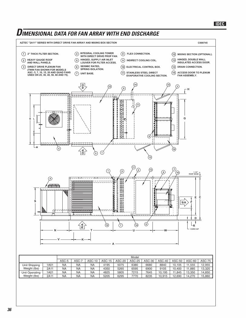
36
DIMENSIONAL DATA FOR FAN ARRAY WITH END DISCHARGE
IDEC
ASC-5 ASC-7 ASC-10 ASC-15 ASC-20 ASC-25 ASC-30 ASC-40 ASC-50 ASC-60 ASC-751A01 NA NA NA 4195 5075 6380 6680 8840 10,105 11,555 12,9552A11 NA NA NA 4350 5265 6595 6900 9105 10,400 11,885 13,3201A01 NA NA NA 4825 5805 7215 7645 10,195 11,845 13,350 14,8502A11 NA NA NA 5205 6295 7770 8235 10,915 12,690 14,270 15,860
Model
Unit ShippingWeight (lbs)
Unit OperatingWeight (lbs)

37
DIMENSIONAL DATA FOR FAN ARRAY WITH END DISCHARGE
ASC-15
ASC-20
ASC-25
ASC-30
ASC-40
ASC-50
ASC-60
ASC-75
ASC-15
ASC-20
ASC-25
ASC-30
ASC-40
ASC-50
ASC-60
ASC-75
19-1/4
20-1/4
17-1/2
17-1/2
17-1/2
L
43-1/2
49-1/2
49-1/2
53-1/2
65-1/2
88
88
88
93
93
104-3/4
S
48-1/2
48-1/2
48-1/2
60-1/2
60-1/2
72-1/2
72-1/2
84-1/2
49-3/8
55
49-5/8
49-5/8
57-3/8
V
59-3/8
59-3/8
60-1/2
60-1/2
72-1/2
81-13/16
81-13/16
90-1/2
MODEL
W
49-3/8
49-3/8
49-3/8
U
73-7/8
73-7/8
73-7/8
T
52
68
77
250-5/16
17-1/4
19-3/4
DIMENSIONS
225-3/16
241-5/16
71
A B C D E F G H K
8
66-1/2
74-1/2
80-1/2
92-1/2
92-1/2
254-3/8
280
287-3/8
293-3/8
318-7/8 123
84
89
92
106
123
20
20
20
58-1/28
8
8
8
8
8
22-13/16
26
8-1/2
1558-1/2
66-1/2
82
82
20
30
30
38
38
84-1/2
84-1/2
99-1/2
117-1/2
72-1/2
54
54
70
70
MODELDIMENSIONS
RNM
14-5/165013-3/4
29-1/2
32-1/2
35-1/2
42-3/8
42-3/8
46
11
13-1/2
20-1/2
20-1/2
20-1/2
9-1/2
123 107-1/2
125-1/2
8
75
75
78-13/16
78-13/16
78-13/16
80
88
66-1/2
66
72
78
15-5/16
20-5/16
50
50
20-5/16
20-5/16
20-5/16
20-5/16
20-5/16
50
62
79
82
IDEC

38
DIMENSIONAL DATA FOR FAN ARRAY WITH DOWN DISCHARGE
IDEC
ASC-5 ASC-7 ASC-10 ASC-15 ASC-20 ASC-25 ASC-30 ASC-40 ASC-50 ASC-60 ASC-751A01 NA NA NA 4485 5390 6765 7115 9390 10,735 12,255 13,8152A11 NA NA NA 4640 5580 6980 7335 9655 11,030 12,585 14,1801A01 NA NA NA 5115 6120 7600 8080 10,745 12,475 14,050 15,7102A11 NA NA NA 5495 6610 8155 8670 11,465 13,320 14,970 16,720
Model
Unit ShippingWeight (lbs)
Unit OperatingWeight (lbs)

39
DIMENSIONAL DATA FOR FAN ARRAY WITH DOWN DISCHARGE
ASC-15
ASC-20
ASC-25
ASC-30
ASC-40
ASC-50
ASC-60
ASC-75
ASC-15
ASC-20
ASC-25
ASC-30
ASC-40
ASC-50
ASC-60
ASC-75
50
62
66
72
78
M
13-3/4
17-1/4
19-3/4
19-1/4
20-1/4
17-1/2
17-1/2
17-1/2
76-5/8
83
64
T
52
68
77
80
88
93
93
104-3/4
47
50
52
52
62
W
49-3/8
49-3/8
49-3/8
49-3/8
55
49-5/8
49-5/8
57-3/8
MODEL
X
34
38
45
V
59-3/8
59-3/8
60-1/2
U
69
71
71
292-3/8
50
50
DIMENSIONS
254-3/8
276-3/8
71
A B C D E G H K L
8
66-1/2
74-1/2
80-1/2
92-1/2
92-1/2
301-3/8
330
337-5/16
349-5/8
366-1/8 123
84
89
92
106
123
54
54
70
58-1/28
8
8
8
8
8
43-1/2
49-1/2
22-13/16
2658-1/2
66-1/2
20-1/2
20-1/2
70
79
82
82
82
84-1/2
84-1/2
99-1/2
117-1/2
72-1/2
8-1/2
15
9-1/2
11
MODELDIMENSIONS
SON
48-1/22050
49-1/2
53-1/2
65-1/2
88
88
88
32-1/2
35-1/2
42-3/8
42-3/8
46
29-1/2
123 107-1/2
125-1/2
8
60-1/2
72-1/2
81-13/16
81-13/16
90-1/2
75
75
66-1/2
38
38
48
48-1/2
48-1/2
24
30
60-1/2
60-1/2
72-1/2
72-1/2
84-1/2
33
36
13-1/2
20-1/2
IDEC
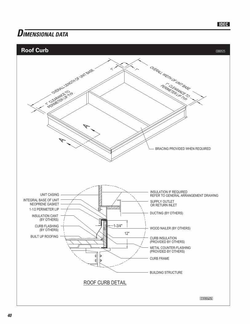
40
DIMENSIONAL DATA
Roof Curb C000525
IDEC
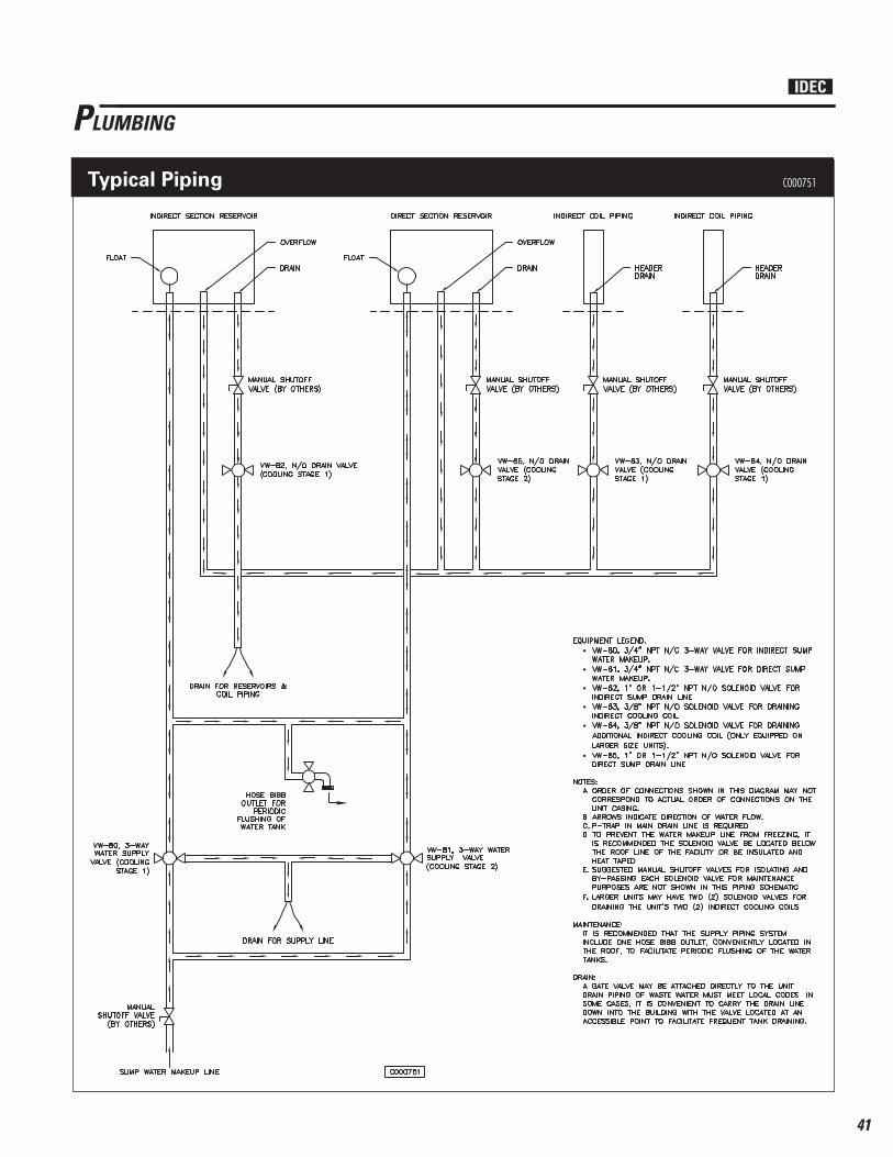
41
PLUMBING
Typical Piping C000751
IDEC

42
CONTROLS
MDT Expert C000740
IDEC

43
CONTROLS
MRT Expert C000739
IDEC
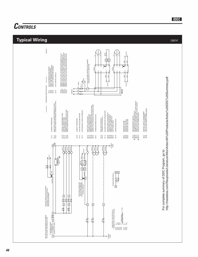
44
CONTROLS
SW
-01
MA
IN D
ISC
ON
NE
CT
SW
ITC
H
CO
MP
ON
EN
T ID
EN
TIF
ICA
TIO
NU
NIT
SH
ALL
BE
GR
OU
ND
ED
AC
CO
RD
ING
TO
TH
E L
AT
ES
T P
RO
VIS
ION
S O
F N
EC
21
FU
-10
CO
NT
RO
L C
IRC
UIT
FU
SE
FU
-10
RE
-57
UN
IT E
NA
BLE
RE
LAY
PS
-10
MA
IN A
IRF
LOW
SW
ITC
HP
S-1
2C
LOG
GE
D F
ILT
ER
SW
ITC
H
120
VA
C
6V
W-8
2
VW
-81
IND
IRE
CT
EV
AP
2-W
AY
N/O
DR
AIN
LIN
E S
OLE
NO
ID V
ALV
EV
W-8
0
IND
IRE
CT
EV
AP
3-W
AY
N/C
SU
PP
LY L
INE
SO
LEN
OID
VA
LVE
VW
-81
RE
-78
INT
ER
LOC
KIN
G R
ELA
YR
E-7
832
INT
ER
LOC
KIN
G R
ELA
Y 33 34R
E-7
8
CU
ST
OM
ER
EX
HA
US
TF
AN
INT
ER
LOC
K
LOW
VO
LTA
GE
TR
AN
SF
OR
ME
RT
R-0
5
UN
IT C
ON
TR
OL
MO
DU
LEU
C-0
1
5
TO
NE
XT
PA
GE
TO
NE
XT
PA
GE
(JU
MP
ER
IF N
OT
US
ED
)3
4
INLE
T A
IR T
EM
PE
RA
TU
RE
SE
NS
OR
TS
-01
KE
YP
AD
/DIS
PLA
Y M
OD
ULE
(R
EM
OT
E)
KP
-01
SP
AC
E T
EM
PE
RA
TU
RE
SE
NS
OR
TS
-02
RE
-33
RE
-36
DIR
EC
T W
AT
ER
PU
MP
MO
TO
R F
US
EF
U-2
5
MT
-80
DIR
EC
T E
VA
P R
EC
IRC
ULA
TIN
G W
AT
ER
PU
MP
RE
-33
SE
CO
ND
ST
AG
E C
OO
LIN
G R
ELA
Y
10F
U-2
5R
E-3
6M
T-8
0
SW
-11
DIR
EC
T E
VA
P L
OW
WA
TE
R L
EV
EL
CU
TO
FF
SW
ITC
H
RE
-36
DIR
EC
T E
VA
P P
UM
P R
ELA
Y
DIR
EC
T E
VA
P 2
-WA
Y N
/O D
RA
IN L
INE
SO
LEN
OID
VA
LVE
VW
-80A
DIR
EC
T E
VA
P 3
-WA
Y N
/C S
UP
PLY
LIN
E S
OLE
NO
ID V
ALV
EV
W-8
1A
7V
W-8
1A
VW
-80A
HT
-01
ELE
CT
RIC
EN
CLO
SU
RE
HE
AT
ER
HT
-01
SW
-01
460/
3/60
CA
UT
ION
: OP
EN
& L
OC
K O
UT
MA
IND
ISC
ON
NE
CT
SW
ITC
H B
EF
OR
ES
ER
VIC
ING
EQ
UIP
ME
NT
.
HU
MID
ITY
TR
AN
DU
CE
RH
S-0
5
SW
-09
100
PE
RC
EN
T O
UT
SID
E A
IR S
WIT
CH
SW
-72
AU
XIL
IAR
Y U
NIT
EN
AB
LE S
WIT
CH
152
151
24 V
AC
13
2T
O U
C-0
1
152
(-)
210
(+)
TR
-06
MT
-14
AC
TU
AT
OR
S W
IRE
D IN
AD
DIT
ION
AL
MIX
ING
BO
X
PA
RA
LLE
L A
S R
EQ
UIR
ED
O/A
-N/C
, R/A
-N/O
MIX
ING
BO
X D
AM
PE
R M
OT
OR
MT
-14
LOW
VO
LTA
GE
DA
MP
ER
TR
AN
SF
OR
ME
RT
R-0
6
CU
RR
EN
T T
RA
NS
DU
CE
RC
T-0
1S
UP
PLY
AIR
TE
MP
ER
AT
UR
E S
EN
SO
RT
S-0
3
MT
-01
MA
IN S
UP
PLY
FA
N M
OT
OR
MT
-02
CO
OLI
NG
TO
WE
R F
AN
MO
TO
R
MA
IN S
UP
PLY
FA
N V
AR
IAB
LE F
RE
QU
EN
CY
DR
IVE
FD
-01
CO
OLI
NG
TO
WE
R F
AN
VA
RIA
BLE
FR
EQ
UE
NC
Y D
RIV
EF
D-0
2
TO
FU
-11
CO
NT
RO
L C
IRC
UIT
TR
AN
SF
OR
ME
RT
R-0
1
TR
-01
MA
IN D
ISC
ON
NE
CT
FU
SE
FU
-11
PB
-01
PO
WE
R D
IST
RIB
UT
ION
BLO
CK
TO
CB
-09
L1 L2 N
U V W
13A 4
1
FD
-01
T3
T2
T1
MT
-01
252
253
RE
-57
L1 L2 N
U V W
13A 4
1
FD
-02
T3
T2
T1
MT
-02
5 (+
)
2 (-
)
5 (+
)
2 (-
)
FU
-11
231
230
TO
UC
-01
251
250
TO
UC
-01
241
240
TO
UC
-01
P10
215
.0
P12
101
P14
001
P16
015
.0
P10
8m
otor
cur
rent
driv
e ou
tput
cur
rent
X10
0
MA
IN S
UP
PLY
FA
N V
FD
(F
D-0
1)P
AR
AM
ET
ER
S F
OR
DD
C C
ON
TR
OL
P10
001
P10
560
.0P
104
60.0
FU
-09
CO
NT
RO
L T
RA
NS
FO
RM
ER
FU
SE
FU
-09
BU
ILD
ING
PR
ES
SU
RE
TR
AN
SD
UC
ER
PT
-13
IND
IRE
CT
EV
AP
2-W
AY
N/O
DR
AIN
LIN
E S
OLE
NO
ID V
ALV
EV
W-8
2
VW
-80
UC
-01
1415
UC
-01
1718
FD
-01
1617
8F
U-2
4R
E-3
5M
T-8
1
RE
-34
RE
-35
9 11
IND
IRE
CT
WA
TE
R P
UM
P M
OT
OR
FU
SE
FU
-24
MT
-81
IND
IRE
CT
EV
AP
RE
CIR
CU
LAT
ING
WA
TE
R P
UM
P
RE
-34
FIR
ST
ST
AG
E C
OO
LIN
G R
ELA
Y
SW
-10
IND
IRE
CT
EV
AP
LO
W W
AT
ER
LE
VE
L C
UT
OF
F S
WIT
CH
RE
-35
IND
IRE
CT
EV
AP
PU
MP
RE
LAY
RE
SIS
TO
R 1
K O
HM
RS
-01
RE
SIS
TO
R 2
K O
HM
RS
-02
RE
SIS
TO
R 4
.02K
OH
MR
S-0
3R
ES
IST
OR
8.0
6K O
HM
RS
-04
MIX
ED
AIR
TE
MP
ER
AT
UR
E S
EN
SO
RT
S-0
4
RU
N T
HIS
WIR
E T
HR
OU
GH
TH
E C
UR
RE
NT
TR
AN
SD
UC
ER
(C
T-0
1) A
PE
RT
UR
E.
C00
0747
Typical Wiring C000747
IDEC
For
com
plet
e su
mm
ary
of D
DC
Pro
gram
, go
to:
http
://m
este
ksa.
com
/fi le
uplo
ads/
Lite
ratu
re/A
ltonA
ztec
/All%
20P
rodu
cts/
Azt
ec%
20D
DC
%20
Sum
mar
y.pd
f
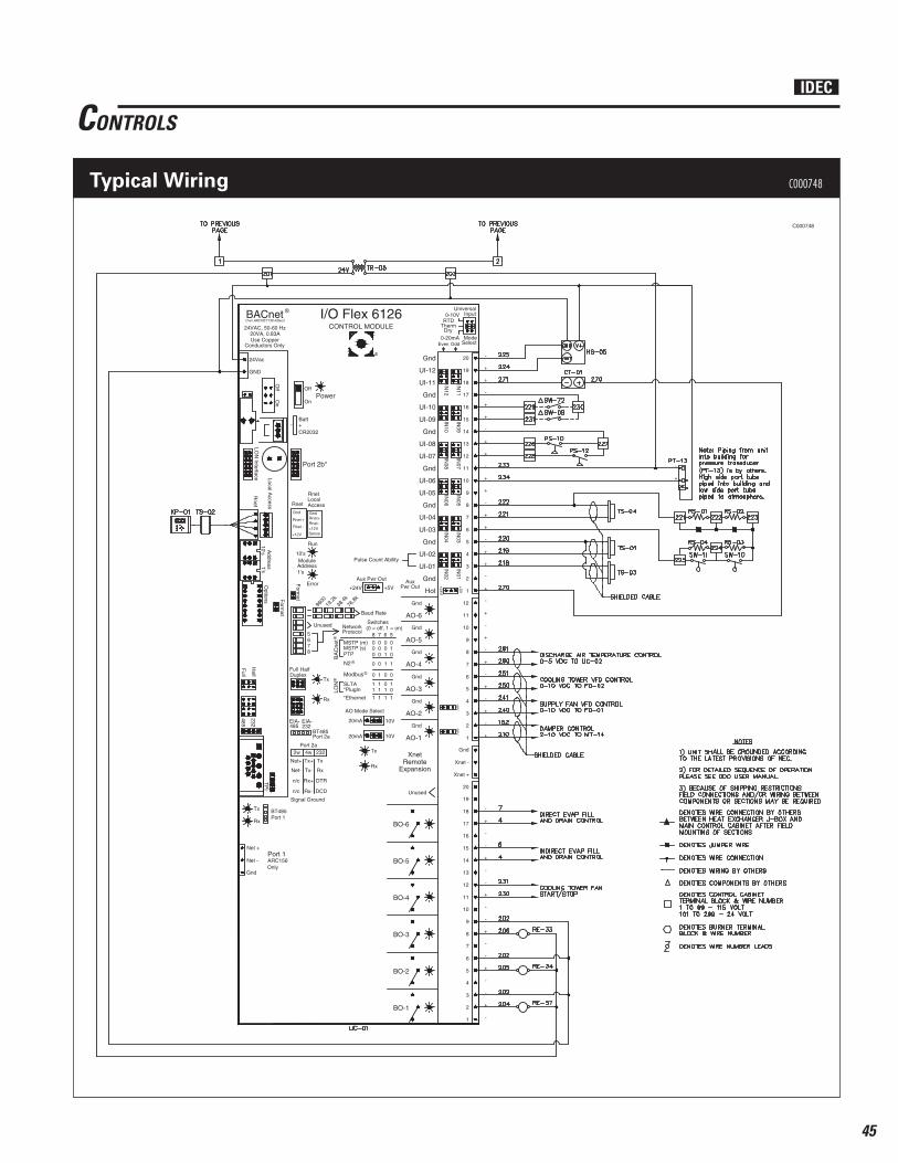
45
10V
+
-
-
+
-
-
+
-
-
+
-
-
+
-
-
+
-
-
+
+
+
-
1
2
3
4
5
6
7
8
9
10
11
12
13
14
15
16
17
18
19
20
1
2
3
4
5
6
7
8
9
10
11
12
13
14
15
16
17
18
19
20
-
+
-
+
-
+
-
+
-
+
-
+
1
2
3
4
5
6
7
8
9
10
11
12
Gnd
UI-11
UI-12
Gnd
UI-09
UI-10
Gnd
UI-07
UI-08
Gnd
UI-05
UI-06
Gnd
UI-03
UI-04
Gnd
UI-01
UI-02
Gnd
AO-6
Gnd
AO-5
Gnd
AO-4
Gnd
AO-3
Gnd
AO-2
Gnd
AO-1
BO-1
BO-2
BO-3
BO-4
BO-5
BO-6
Unused
IN12
IN11
IN10
IN09
IN08
IN07
IN06
IN05
IN04
IN03
IN02
IN01
Even Odd
10V
Universal
Mode
RTD0-10V
0-20mA
ThermDry
Input
Select
XnetRemote
ExpansionRx
Tx
AO Mode Select
10V20mA
20mA 10V
Pulse Count Ability
+5V
+24V
Aux GndAux Pwr Out
+5V+24V Pwr OutHot
CONTROL MODULE
BACnet ®
24VAC, 50-60 Hz20VA, 0.83A
Conductors OnlyUse Copper
®
I/O Flex 6126
24Vac
GND
Off
On
Local Access
Rnet
Address
10's1's
Full
Half
485
232
TP
I
LON
Interface
PowerOff
Batt
CR2032- +
Port 2b*
Gnd
Rnet +
Rnet -
+12V
Rnet
+12V
Rnet
Rnet-
GndRnet+
Sense
LocalAccess
Run
Error
Rx
Tx
Module10's
9600
76.8
k19
.2k
38.4
k
Baud Rate
Full HalfDuplex
BT485
BT485
Port 1
Tx
Rx
Options F
ormat
232EIA- EIA-485
Port 1
Port 2a
Unused
5678
NetworkSwitches(0 = off, 1 = on)
MSTP (m)MSTP (s)PTP
SLTA*PlugIn
*Ethernet
8 7 6 5Protocol
0 0 0 00 0 0 10 0 1 0
0 0 1 1
0 1 0 0
1 1 0 11 1 1 0
1 1 1 1
BA
Cne
t
N2
Modbus
LON
®
®
®
®
Port 2a2w 4w
Tx+
n/c
n/c
Net+
Rx+
Rx-
Tx-Net-
232
Tx
DTR
DCD
Rx
Signal Ground
Address1's
On
Form
at
ARC156Only
+
+
-
+
+
-
+
+
-
+
+
-
+
+
-
Net +
Gnd
Net -
Gnd
Xnet -
Xnet +
-
+
-
C000748
CONTROLS
Typical Wiring C000748
IDEC

46
AZTEC ASC TYPICAL SPECIFICATIONS1.0 GENERAL1.1 (Choose one) Furnish and install a “1A01” Series Aztec ASC-______-1A01
Packaged Indirect HVAC unit complete with blower section, direct drive motor/blower, fl at bank fi lter section, integral cooling tower, indirect cooling coil section, and inlet louver with birdscreen. The entire unit is to be manufactured by Aztec Sensible Cooling, Dallas, Texas or an approved equal. The unit shall include all components and accessories as set forth herein.
Furnish and install a “2A11” Series Aztec ASC-______-2A11
Packaged Indirect/Direct Evaporative HVAC unit complete with blower section, direct drive motor/blower, fl at bank fi lter section, integral cooling tower, indirect cooling coil section, direct evaporative cooling section and inlet louver with birdscreen. The entire unit is to be manufactured by Aztec Sensible Cooling, Dallas, Texas or an approved equal. The unit shall include all components and accessories as set forth herein.
1.2 Unit shall be designed to insure against air stratifi cation across fi lters and evaporative cooling media. Air velocities across fi lters and evaporative cooling media shall not exceed 500 FPM.
1.3 Complete unit shall be ETL listed. All units shall be built up with orientation and connection locations as indicated on drawings.
1.4 Capacities shall be as scheduled on drawings and/or equipment schedule.
2.0 CABINET2.1 The unit shall consist of sections required to incorporate the
components indicated on the plans and schedule.2.2 The wall and roof panels of the unit shall be fabricated of heavy
gauge galvanized steel formed members. The walls and roof structure shall accommodate up to 1" of insulation.
2.3 The wall panels shall form a self-framing casing with no additional structural support required. All panels shall be sealed airtight with a sealant.
2.4 The fl oor panels will be built with 1" interlocking standing seam and be suitably reinforced with framing members as required to support the internal components of the unit and be both water and airtight.
2.5 Access doors shall be of the double wall, insulated type and provided with live neoprene bulb gaskets, hinges, and latches capable of applying additional sealing as required.
2.6 The roof of the unit shall have a minimum 11/2″ interlocking standing seam construction. All seams will be caulked and sealed to be weathertight and airtight.
2.7 All exterior surfaces shall be cleaned to prepare the galvanized surface before applying a specially formulated corrosion resistant combination prime and fi nish coating of durable 500 hour salt spray resistant, dark tan, acrylic enamel.
3.0 STRUCTURAL BASE3.1 Unit or individual unit section shall be fabricated with either
a rigidly formed 12 gauge galvanized steel or structural steel base frame electrically welded to form a rigid chassis suitably reinforced and braced to permit the loading, shipping, unloading, rigging, and general handling of the completed sections without damage to assembled components due to normal handling techniques. If fabricated in sections, they shall be joined together by bolting. Structural components shall be of such design as to provide adequate support for each section and the complete assembly when the unit is supported around its base perimeter.
3.2 Lifting lugs shall be provided as required for each section.3.3 Base frame of each section shall be designed to accept full
perimeter roof curb as shown in drawings. Base frame and outside casing shall be specifi cally designed to shed water away from all curb penetrations.
4.0 INSULATION4.1 Wall panels, roof, and fl oor shall be insulated with 1" thick,
1-1/2# density mat faced fi berglass insulation.4.2 Insulation shall meet the requirements of the following codes
and specifi cations: NFPA 90A and NFPA 90B ASTM C 1071 Type II TIMA Standard AHC-101 HH-I-545B Type II
Insulation will be tested in accordance with ASTM E-84, UL 723, and NFPA-255 and will not exceed:
25 Flame spread 50 Smoke Developed
4.3 Insulation shall be held in place with adhesive and mechanical fasteners. The mechanical fasteners shall be spaced in accordance with the latest edition of SMACNA “HVAC Duct Construction standards”.
5.0 SUPPLY AIR BLOWER SECTION5.1 The blower section shall include centrifugal, backward
airfoil SWSI plenum type blower and shall be complete with direct drive motor. The blower in accordance with AMCA (Air Movement and Control Association) Standard 210. The blowers shall be designed to operate without conventional scroll housing. All blower wheels shall have tapered and spun wheel cones or shrouds providing stable fl ow and high rigidity. The wheels shall be non-overloading type. The blades shall be continuously welded, airfoil type, designed for maximum effi ciency and quiet operation. All air ratings are based on delivery against the external static pressure specifi ed with all optional equipment in place and operating. All blowers will be dynamically balanced on precision electronic vibration amplifying equipment to insure quiet, smooth running, trouble free operation. Flexible ducting shall be provided between blower inlet and unit casing.
IDEC

47
AZTEC ASC TYPICAL SPECIFICATIONS5.2 Blower motor shall be designed to suit the characteristics of
the available electric service shown on drawings. Motor will be (energy effi cient ODP).
5.3 Motor and blower assembly shall be mounted on a common structural steel base under which vibration isolators shall be anchored to the fl oor. Vibration isolators shall be spring type with seismic restraint to restrict vertical and horizontal motion. The isolation base shall be complete with hold down bolts and wood blocking to maintain the isolation base in rigid position for shipping.
5.4 Supply fan motor shall be controlled by Variable Frequency Drive (VFD). The DDC control system will modulate the VFD to maximize system effi ciency and performance based on sensed environmental conditions. The VFD shall be mounted inside cabinet suitable for rooftop applications.
6.0 INDIRECT EVAPORATIVE COOLING SECTION6.1 The indirect evaporative cooling section of the unit shall consist
of an indirect cooling coil [A] and an integral cooling tower [B] as described below:
A. INDIRECT COOLING COIL: The indirect cooling coil in the unit shall be of the drainable, counterfl ow type. The coil’s fi nning material shall be of corrugated type and mechanically bonded to the coil’s tubing. The coil shall be equipped with both a drain and vent connection.
The header and the supply and return coil connection of the indirect coil shall be copper, located on one end of the coil and internally plumbed at the factory to the recirculating pump provided with the unit’s integral cooling tower.
The unit’s indirect coil drain connection or the chilled water supply line from the cooling tower in the unit, whichever has the lowest drain point, shall be plumbed to the exterior of the unit’s housing and provided with a manually operated drain valve.
B. INTEGRAL COOLING TOWER: The unit’s integral cooling tower shall be provided with the following factory pre-assembled components: 2" aluminum mesh, washable type intake air fi lters; welded stainless steel sump construction; stainless steel housing construction; propeller type, corrosion coated, direct or belt driven exhaust fan; evaporative cooling media; cooling tower cooling media water distribution header or headers; recirculating pump manifold assembly; factory set, calibrated butterfl y or ball type brass water balancing valve, factory adjusted, brass lever control valve with a plastic fl oat ball; sump drain connection; sump overfl ow connection; sump water fi ll and make-up line connection; adjustable brass water bleed valve with the copper bleed tubing plumbed to the cooling tower’s overfl ow stand pipe; recirculating pump low sump water lever shutoff switch; submersible type recirculating pump.
7.0 DIRECT EVAPORATIVE SECTION (2A11 Series only)7.1 The evaporative section(s) shall have a 51/2" deep sump with
welded seams and corners. The sump shall be constructed of 304 stainless steel and will be factory leak tested prior to shipment. The remainder of the direct evaporative cooling section shall also be constructed of 304 stainless steel.
7.2 The cooling media shall be 12" deep fl uted Fiberdek, high effi ciency evaporative media, impregnated with an insoluble antirot chemical. The face velocity shall be equal to or less than that shown on the air handler schedule, in no case shall the face velocity exceed 500 FPM.
7.3 The evaporative cooling section shall include a submersible pump with U.L. listed, hermetically sealed, dielectric oil-fi lled motor and Buna-N seal. Horsepower rating of the pump shall not be less than 1/6 HP. Pump to be centrifugal type.
7.4 The water distribution system shall be constructed of PVC plumbing and include, but not be limited to, the following items: pump riser; factory installed water regulator valve to permit fi eld adjustment of water fl ow over media; 1" drain connection; 11/2" overfl ow line; 3/4" water control valve; adjustable bleed valve to allow continuous bleed off, thus minimizing the build up of minerals and salts; cleanable water distribution header over the complete width of media.
8.0 OUTSIDE AIR INLET LOUVER8.1 Louver frame and blades shall be galvanized steel with riveted
or welded construction.8.2 Louver shall include galvanized birdscreen.8.3 Louver design shall be of the drainable type and be tested to
AMCA Standard 500 and licensed to bear the AMCA seal.8.4 Louver shall be hinged for service and fi lter access on all
100% outside air units.9.0 FILTER SECTION 9.1 Flat fi lter rack shall be designed for 2" thick fi lters of size and
quantity as shown on drawings. Filter rack shall be of the front access type. Filters shall be mounted in galvanized steel frames.
9.2 Filter media shall be nominal 2" thick, Merv 8 disposable type design. All fi lters shall be listed by Underwriters Laboratories as Class 2.
OPTIONAL EQUIPMENT • 2" Fiberglass insulation• Double wall and roof cabinet construction• TEFC motors• Mixing section with return air and outside air dampers• 12" or 18" high full perimeter roof curb• Direct drive centrifugal, backward airfoil, SWSI plenum type
fan arrays• MERV 11 and MERV 14 supply air fi lters• Direct expansion or chilled water cooling coil• Variable frequency drive on cooling tower fan• Smoke detector• Firestat• Copper plumbing• UL labeled control panel
IDEC
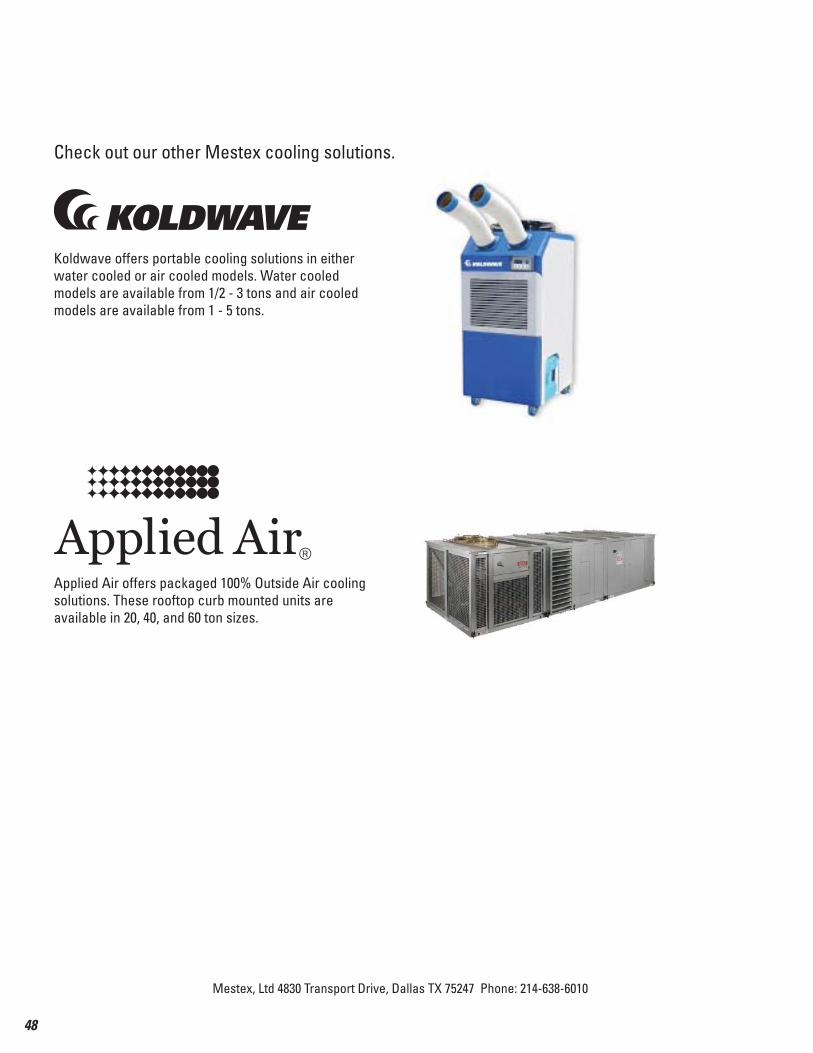
48
Mestex, Ltd 4830 Transport Drive, Dallas TX 75247 Phone: 214-638-6010
Check out our other Mestex cooling solutions.
Koldwave offers portable cooling solutions in either water cooled or air cooled models. Water cooled models are available from 1/2 - 3 tons and air cooled models are available from 1 - 5 tons.
Applied Air offers packaged 100% Outside Air cooling solutions. These rooftop curb mounted units are available in 20, 40, and 60 ton sizes.