cookson owner’s manualassets.cooksondoor.com/pdfs/techinfo/03-07-11/auto-test-tube-motor... ·...
TRANSCRIPT

3117(1) ECN 0951 BY RG 10/28/10 1 PATENT NO. 6,155,324
COOKSON OWNER’S MANUAL
ELECTRIC CLUTCH RELEASE
FOR
TUBULAR MOTOR
- 2 -
SPECIFICATIONS
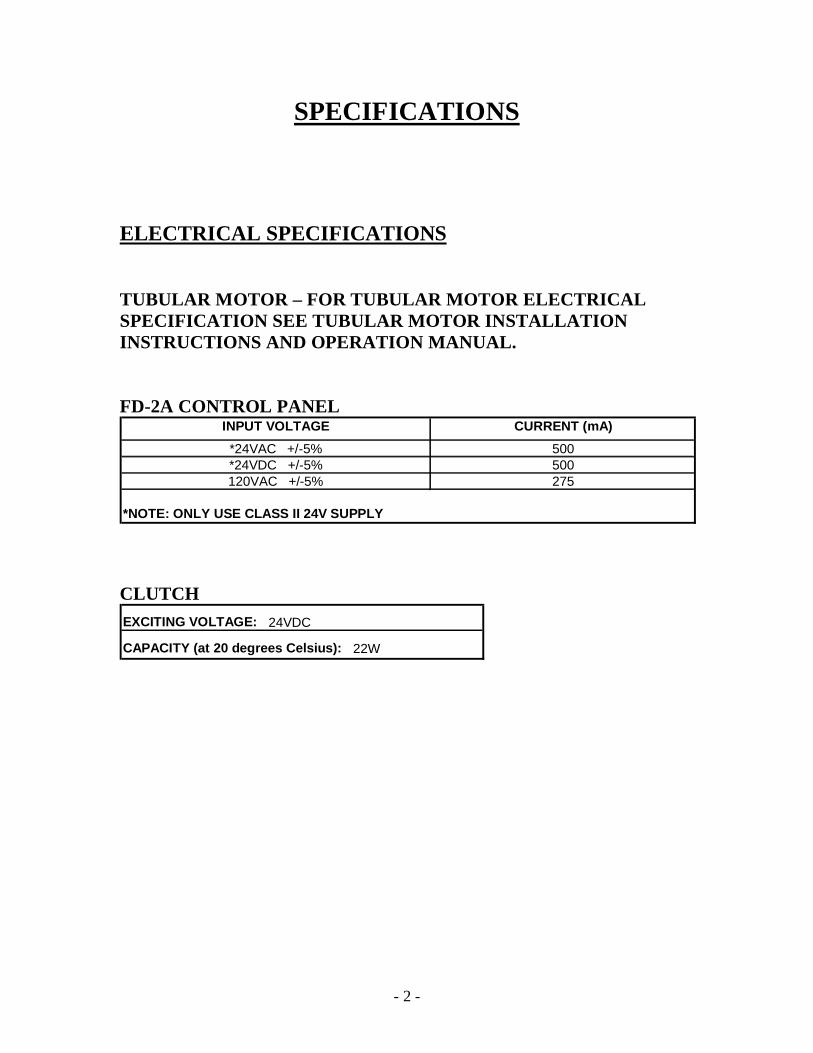
ELECTRICAL SPECIFICATIONS
TUBULAR MOTOR – FOR TUBULAR MOTOR ELECTRICALSPECIFICATION SEE TUBULAR MOTOR INSTALLATIONINSTRUCTIONS AND OPERATION MANUAL.
FD-2A CONTROL PANELINPUT VOLTAGE CURRENT (mA)*24VAC +/-5% 500*24VDC +/-5% 500120VAC +/-5% 275
*NOTE: ONLY USE CLASS II 24V SUPPLY
CLUTCHEXCITING VOLTAGE: 24VDC
CAPACITY (at 20 degrees Celsius): 22W

- 3 -
MECHANICAL SPECIFICATIONS
TUBULAR MOTOR – FOR TUBULAR MOTOR MECHANICALSPECIFICATIONS SEE TUBULAR MOTOR INSTALLATIONINSTRUCTIONS
ELECTRO-MAGNETIC CLUTCHBORE (ROTOR): 0.625"STATIC TORQUE: 217 IN-LBSMAX REVOLUTION: 4500 RPMAIR GAP: 0.2 MMWEIGHT: 4.0 LBS.
ELECTRO-MAGNETIC CLUTCH
FD-2A CONTROL PANEL

- 4 -
THEORY OF OPERATION
GENERAL DESCRIPTION
The electric clutch release for tubular motor operator possesses a featurewhich, in the event of a power failure or power loss or, when an alarmcondition is sensed from a fire alarm and/or smoke detector, the clutchdisengages and the door will close without delay. Once the power/alarm isrestored the unit engages and the door is ready for normal operation. Powerto the unit (24VAC/DC or 115VAC) maintains brake engagement via theelectric clutch. The alarm system and/or smoke detector are wired such thatan alarm condition will interrupt the power to the clutch, allowing the doorto close under normal fire drop operation.
NOTE: Refer to Fire Door Manufacturer’s Installation Instructions for doorinstallation and operation.
NOTICETHIS OPERATOR IS NOT A FIRE ALARM SYSTEM! IT CANNOTDETECT A FIRE CONDITION!
WARNINGTO REDUCE THE RISK OF INJURY TO PERSONS, USE THISOPERATOR ONLY WITH ROLLING DOORSUSE ONLY WITH APPROVED TYPE OF DOOR
SCENARIOS1.1 Unit has AC power and no alarm condition present
Tubular motor normally operates the door. Electric clutch is engagedand maintains door position.
1.2 Unit has no power or alarm condition presentElectric clutch disengages and the door will close without delay.Motor cannot operate the door. Once the power is restored or alarm iscleared motor will operate the door normally (resetting of door is notrequired).

- 5 -
MOUNTING
The electric clutch that maintains the door position when engaged or allowsthe door to close under normal fire drop operation when disengaged ismounted on the door bracket, on a 5/8” release shaft.The centrifugal governor that controls the speed of the door when the doorcloses under normal fire drop operation is mounted on the door bracket.A roller chain connects the release shaft sprocket to the centrifugal governorsprocket.The FD-2A control panel is mounted on the wall adjacent to the door.
ELECTRIC CLUTCH RELEASE ASSEMBLY

- 6 -
ADDITIONAL INFORMATION
To ensure correct operation of the electric clutch release verify thefollowing:
The centrifugal governor is properly installed and the set screw on itssupport is tightened.The centrifugal governor’s brake shoes assembly rotates freely insidethe drum.The sprockets on the 5/8” release shaft and on the centrifugalgovernor are aligned.The keys for the electro-magnetic clutch and main sprockets are inplace and the set screw is tightened.A gap of +/- 1/16” exists at the electro-magnetic clutch mounting taband mounting screw washers. This is factory preset and allows theelectro-magnetic clutch to engage or disengage. DO NOT TIGHTENTHE ELECTRO-MAGNETIC CLUTCH MOUNTING TABAGAINST THE MOUNTING POST.
Abnormal friction is not detected at the release assembly whenrotating the door barrel.
WARNINGA COVER MUST BE INSTALLED OVER DOOR BRACKET ANDSPROCKETS WHEN MOVING PARTS ARE EXPOSED LESS THAN8 FEET FROM THE FLOOR.

- 7 -
INSTALL POWER WIRING
Unit requires one switched power input, 24VDC or 24VAC or 115VACaccording to wiring diagram and local codes. Minimum wire size is 20GAcopper (use heavier wire for longer runs).
ELECTRICAL CONNECTIONS FOR FD-2A CONTROL PANELTO ALARM SYSTEM/SMOKE DETECTORS
WARNING: DOOR WILL CLOSE UNDER NORMAL FIREDROP OPERATION WHEN UNIT HAS NO POWER. TOREDUCE RISK OF INJURY, ALWAYS SERVICE WITH THEDOOR IN CLOSED POSITION
- 8 -
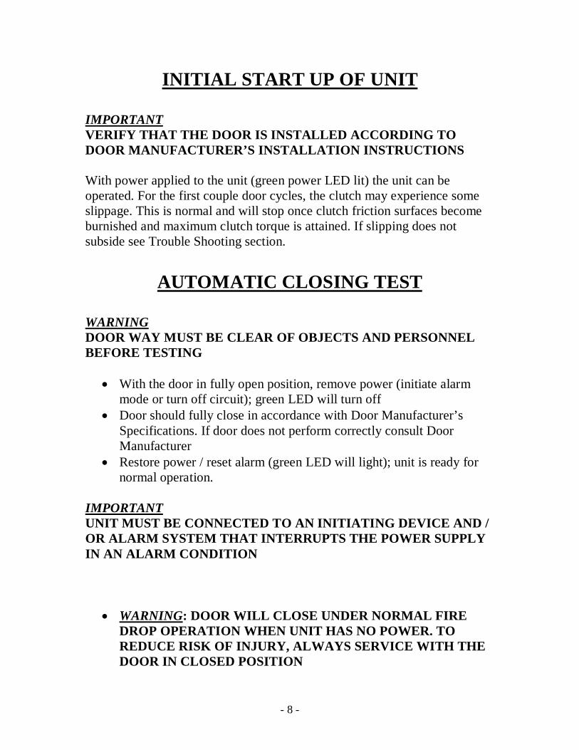
INITIAL START UP OF UNIT
IMPORTANTVERIFY THAT THE DOOR IS INSTALLED ACCORDING TODOOR MANUFACTURER’S INSTALLATION INSTRUCTIONS
With power applied to the unit (green power LED lit) the unit can beoperated. For the first couple door cycles, the clutch may experience someslippage. This is normal and will stop once clutch friction surfaces becomeburnished and maximum clutch torque is attained. If slipping does notsubside see Trouble Shooting section.
AUTOMATIC CLOSING TEST
WARNINGDOOR WAY MUST BE CLEAR OF OBJECTS AND PERSONNELBEFORE TESTING
With the door in fully open position, remove power (initiate alarmmode or turn off circuit); green LED will turn offDoor should fully close in accordance with Door Manufacturer’sSpecifications. If door does not perform correctly consult DoorManufacturerRestore power / reset alarm (green LED will light); unit is ready fornormal operation.
IMPORTANTUNIT MUST BE CONNECTED TO AN INITIATING DEVICE AND /OR ALARM SYSTEM THAT INTERRUPTS THE POWER SUPPLYIN AN ALARM CONDITION
WARNING: DOOR WILL CLOSE UNDER NORMAL FIREDROP OPERATION WHEN UNIT HAS NO POWER. TOREDUCE RISK OF INJURY, ALWAYS SERVICE WITH THEDOOR IN CLOSED POSITION

- 9 -
MAINTENANCE SCHEDULE
CHECK AT THE LISTED INTERVALS THE ITEMS IN THEFOLLOWING CHART:
ITEM PROCEDURE EVERY3 MONTHS
EVERY6 MONTHS
EVERY12 MONTHS
Roller chain Check and lubricate* XSprockets Check for alignment X
Check set screw tightness XFasteners Check & tighten as req'd X
Centrifugal brake Check drum for debris Xand/or rust & clean as req'd
*- Use SAE 30 Oil (Never use grease or silicone spray).
Electromagnetic Clutch Friction Material – The electromagnetic clutch isfactory adjusted and should not require service. The friction surfaces shouldbe kept free of debris, grease, or oil.
Inspect and service whenever a malfunction is observed orsuspected.CAUTION: BEFORE SERVICING, ALWAYS DISCONNECTOPERATOR FROM POWER SUPPLY.WARNING: DOOR WILL CLOSE UNDER NORMAL FIREDROP OPERATION WHEN UNIT HAS NO POWER. TOREDUCE RISK OF INJURY, ALWAYS SERVICE WITH THEDOOR IN CLOSED POSITION
WHEN ORDERING PARTS PLEASE SUPPLY THE FOLLOWING INFORMATION:PART NUMBER - DESCRIPTION - MODEL NUMBER - JOB NUMBER - DOOR MARK
ADDRESS ORDER TO:COOKSON ROLLING DOORS2417 S. 50TH AVE.PHOENIX, AZ 85043(602) 272-4244ATTN: CUSTOMER SERVICE
- 10 -
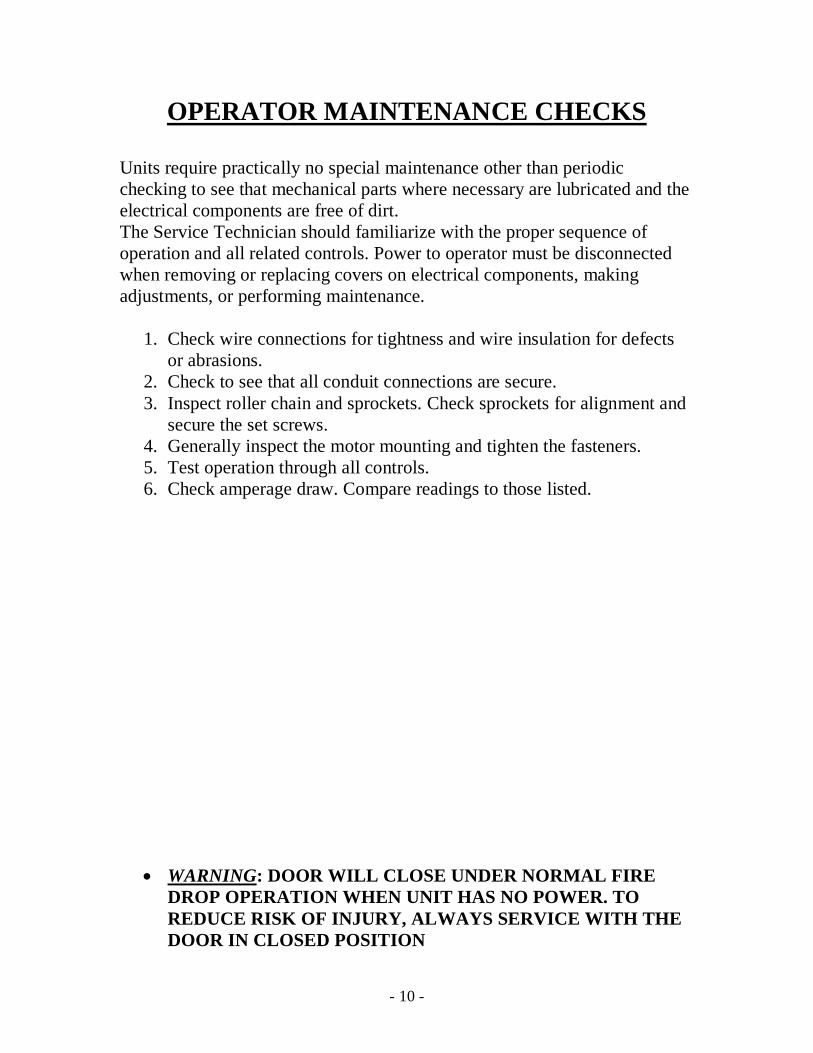
OPERATOR MAINTENANCE CHECKS
Units require practically no special maintenance other than periodicchecking to see that mechanical parts where necessary are lubricated and theelectrical components are free of dirt.The Service Technician should familiarize with the proper sequence ofoperation and all related controls. Power to operator must be disconnectedwhen removing or replacing covers on electrical components, makingadjustments, or performing maintenance.
1. Check wire connections for tightness and wire insulation for defectsor abrasions.
2. Check to see that all conduit connections are secure.3. Inspect roller chain and sprockets. Check sprockets for alignment and
secure the set screws.4. Generally inspect the motor mounting and tighten the fasteners.5. Test operation through all controls.6. Check amperage draw. Compare readings to those listed.
WARNING: DOOR WILL CLOSE UNDER NORMAL FIREDROP OPERATION WHEN UNIT HAS NO POWER. TOREDUCE RISK OF INJURY, ALWAYS SERVICE WITH THEDOOR IN CLOSED POSITION
- 11 -
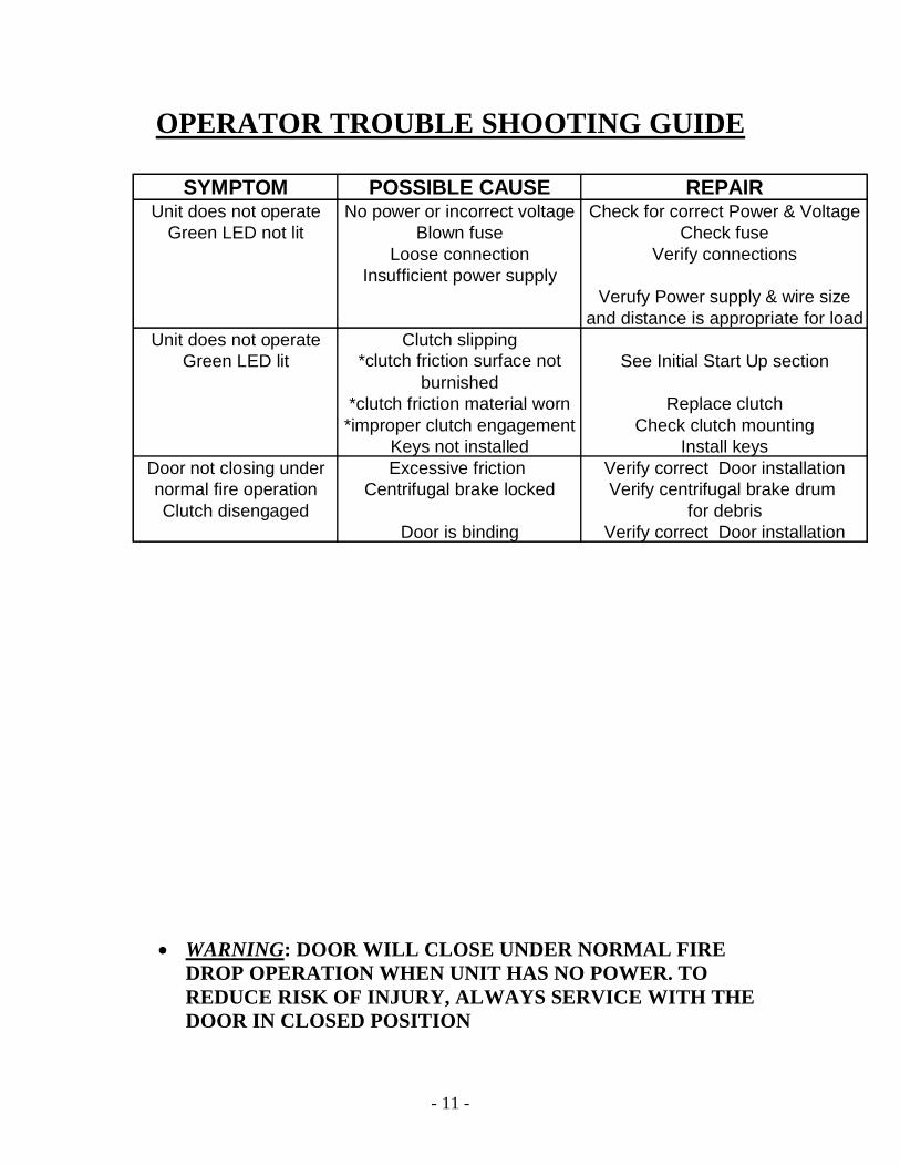
OPERATOR TROUBLE SHOOTING GUIDE
SYMPTOM POSSIBLE CAUSE REPAIRUnit does not operate No power or incorrect voltage Check for correct Power & Voltage
Green LED not lit Blown fuse Check fuseLoose connection Verify connections
Insufficient power supplyVerufy Power supply & wire size
and distance is appropriate for loadUnit does not operate Clutch slipping
Green LED lit *clutch friction surface notburnished
See Initial Start Up section
*clutch friction material worn Replace clutch*improper clutch engagement Check clutch mounting
Keys not installed Install keysDoor not closing under Excessive friction Verify correct Door installationnormal fire operation Centrifugal brake locked Verify centrifugal brake drumClutch disengaged for debris
Door is binding Verify correct Door installation
WARNING: DOOR WILL CLOSE UNDER NORMAL FIREDROP OPERATION WHEN UNIT HAS NO POWER. TOREDUCE RISK OF INJURY, ALWAYS SERVICE WITH THEDOOR IN CLOSED POSITION

- 12 -

3116(1) ECN 0951 BY RG 10/28/10 - 1 -
INSTALLATION INSTRUCTIONS
AND
OPERATION MANUAL
TUBULAR MOTOR 550 DMITUBULAR MOTOR 6100 DMI

3116(1) ECN 0951 BY RG 10/28/10 - 2 -
IMPORTANT INSTALLATION INSTRUCTIONS
WARNING: To reduce the risk of severe injury or death read andfollow all installation instructions
1. Do not connect the door operator to the power source until instructed todo so.
2. Locate the switch/control station:- within sight of the door- at a minimum height of 5 feet from the floor so small children cannot reachit- away from all moving parts of the door.
3. Make sure the available power supply to be connected to the operator is ofthe same voltage, frequency, phase, and wattage as indicated for theoperator.
4. Read and understand the wiring diagrams of the operator and theswitch/control station, and any other equipment to be connected to theoperator.
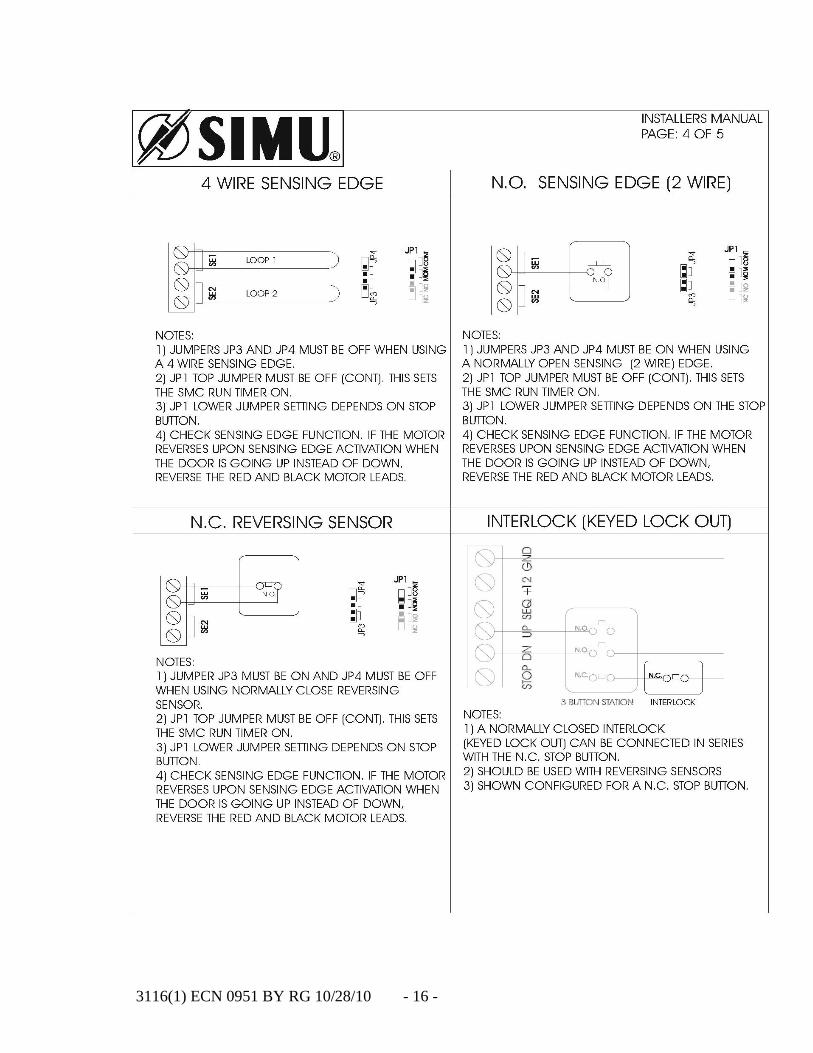
5. To avoid damage to the door and operator, make all door locksinoperative. Secure locks in the unlocked position, or install externalelectrical interlocks to prevent operation with the locks engaged. (NOTE:external electrical interlocks should be provided only with a Smart MotorControl (SMC).
6. Always disconnect power when installing or servicing the door operatoror the door itself.
7. All wiring is to comply with National Electric Code (NEAC) and localcode requirements.
8. Consult factory for any changes as they may affect the operation of thedoor and result in damage or injuries.

3116(1) ECN 0951 BY RG 10/28/10 - 3 -
SPECIFICATIONS
TUBULAR MOTOR TYPE 550 DMI
Voltage………………………………………….115 / 1 phase / 60 HzWatts…………………………………………….210Amps…………………………………………….2.1Protection index…………………………………IP44Torque………………………………………..…440 in.lb.Speed…….………………………………………12 rpmLimit adjustment…………………………………ProgressiveLimit switch (max. turns)………………………...28Run time………………………………………….5 min.Override………………………………………….manualDMI reduction ratio………………………………27:1Cable length………………………………………8 ft
TUBULAR MOTOR TYPE 6100 DMI
Voltage………………………………………..….115 / 1 phase / 60 HzWatts……………………………………….…….430Amps……………………………………….…….3.8Protection index…………………………….……IP44Torque……………………………………………880 in.lb.Speed…….………………………………………14 rpmLimit adjustment…………………………………ProgressiveLimit switch (max. turns)………………………...28Run time………………………………………….5 min.Override………………………………………….manualDMI reduction ratio…………………..…………55:1Cable length……………………………..………8 ft

3116(1) ECN 0951 BY RG 10/28/10 - 4 -
INSTALLATION INSTRUCTIONS
Tubular motor mounts inside the door’s barrel. Based on the pipe diameter, asleeve adapter or ring adapters mounted inside the pipe are used tocompensate for the difference between the outside diameter of the motor andthe inside diameter of the pipe. When inserting the tubular motor into thebarrel ensure that the plastic tab on the motor aligns with the keyway in theadapter. The crown at the opposite end of the motor will fit inside a drivewheel or differential (depending on the door type). When inserting the motorinto the barrel make sure that the motor is parallel with the pipe and that themotor slides completely into the barrel. Gently rotate the tubular motorwhile pushing it in to allow for the crown to engage with the drivewheel/differential.
Tubular Motor

3116(1) ECN 0951 BY RG 10/28/10 - 5 -
Tubular motors are supported by two motor mounting angles bolted to thedrive bracket plate. See the drawings below for motor mountingconfigurations.
3116(1) ECN 0951 BY RG 10/28/10 - 6 -
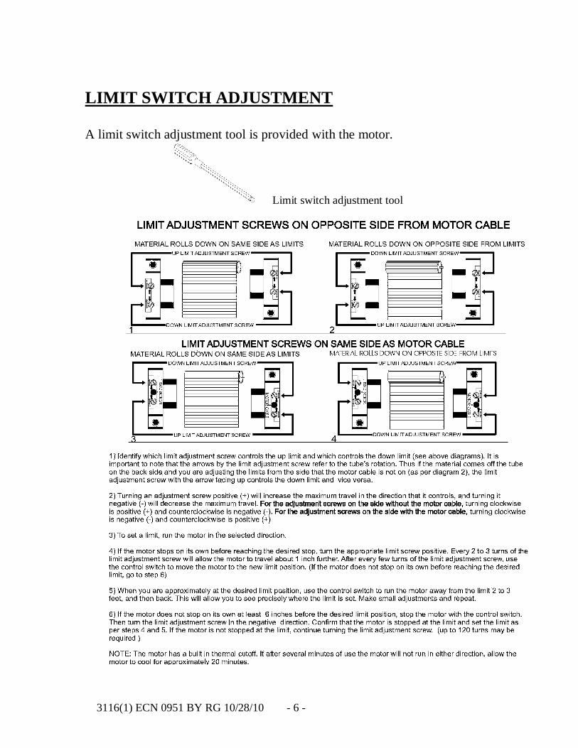
LIMIT SWITCH ADJUSTMENT
A limit switch adjustment tool is provided with the motor.
Limit switch adjustment tool

3116(1) ECN 0951 BY RG 10/28/10 - 7 -
WIRING INSTRUCTIONS
WARNING
- Do not install any wiring or attempt to run the operator withoutchecking the wiring diagrams first.
- Disconnect power before proceeding with any wiring.- Do not turn on power until you have finished making all power and
control wiring connections.- The operator must be properly grounded. Failure to properly ground
the operator could result in electric shock and serious injury or death.- To avoid damage to the door and operator, make all door locks
inoperative. Secure locks in the unlocked position, or install externalelectrical interlocks to prevent operation with the locks engaged.(NOTE: external electrical interlocks should be provided only with aSmart Motor Control (SMC).
- Do not change closing control from constant pressure to momentarypressure without installing a sensing edge. This could result in seriousinjury or death to person(s) trapped beneath the door.
- After installation, ensure that the operator, lock sensor, controls, andsensing edge or other entrapment protection devices have been testedand function properly.
3116(1) ECN 0951 BY RG 10/28/10 - 8 -
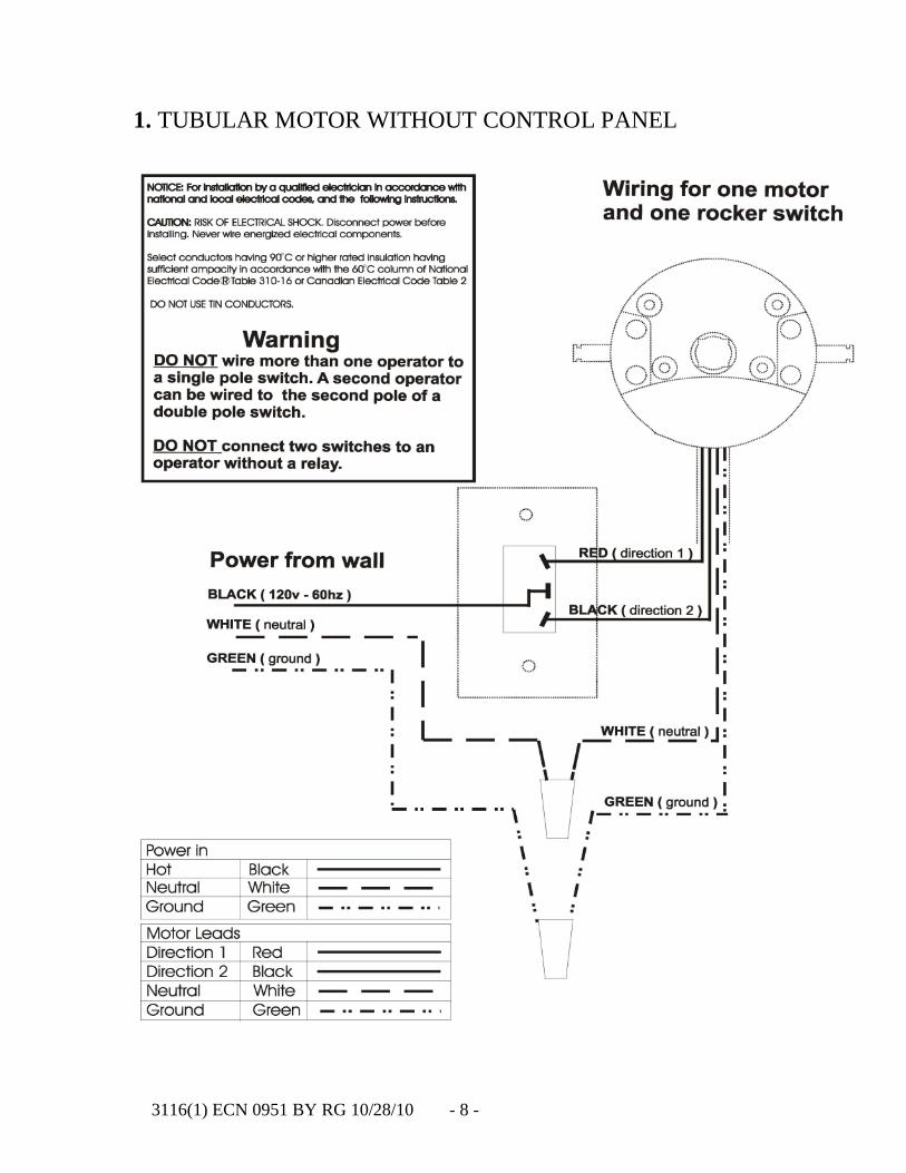
1. TUBULAR MOTOR WITHOUT CONTROL PANEL

3116(1) ECN 0951 BY RG 10/28/10 - 9 -

3116(1) ECN 0951 BY RG 10/28/10 - 10 -
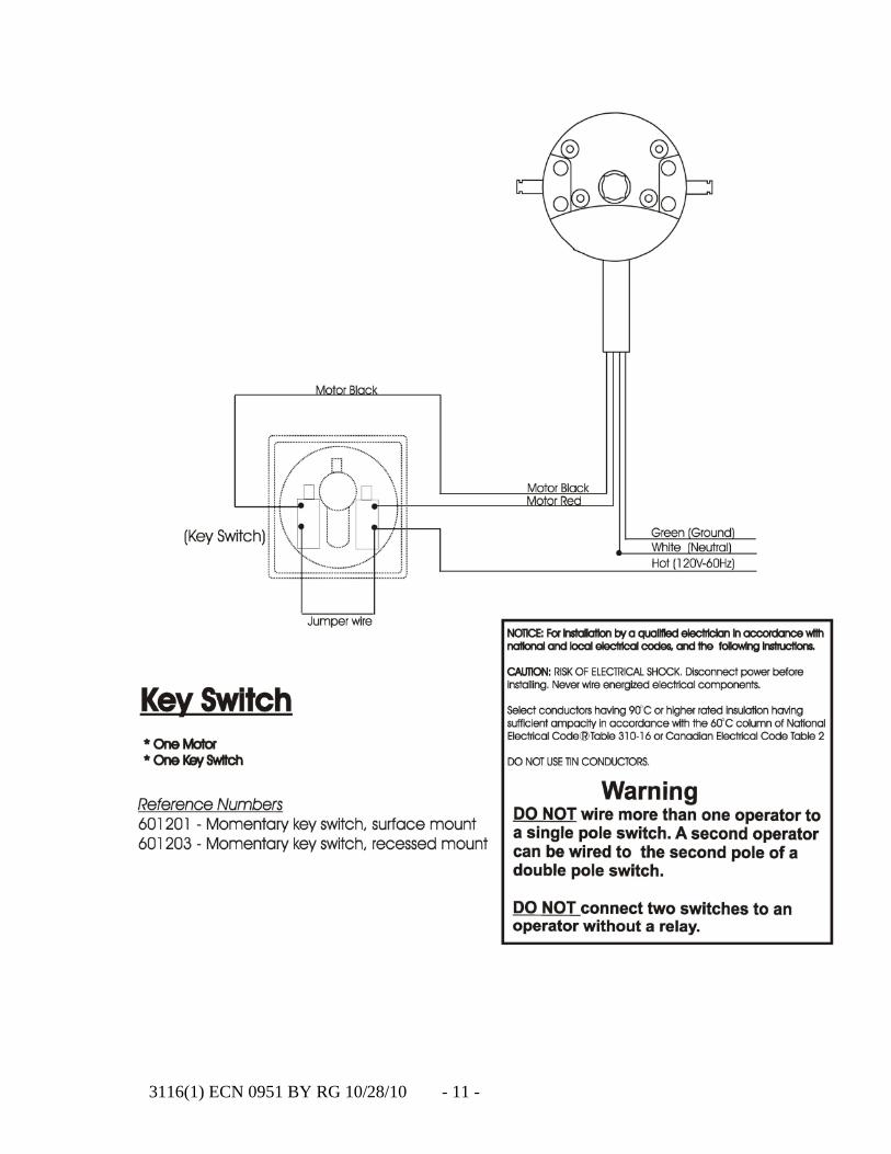
3116(1) ECN 0951 BY RG 10/28/10 - 11 -

3116(1) ECN 0951 BY RG 10/28/10 - 12 -
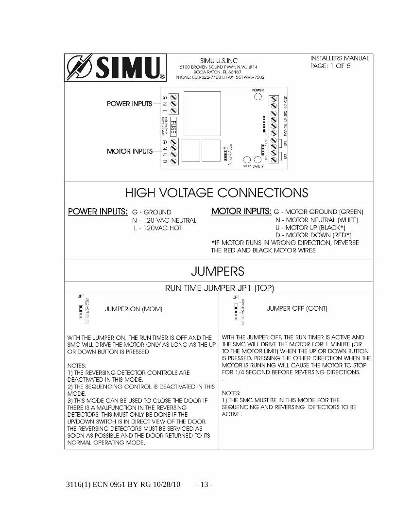
3116(1) ECN 0951 BY RG 10/28/10 - 13 -

3116(1) ECN 0951 BY RG 10/28/10 - 14 -

3116(1) ECN 0951 BY RG 10/28/10 - 15 -
3116(1) ECN 0951 BY RG 10/28/10 - 16 -

3116(1) ECN 0951 BY RG 10/28/10 - 17 -
3116(1) ECN 0951 BY RG 10/28/10 - 18 -
OPERATING INSTRUCTIONS
Tubular motors have a built-in thermal cut-off. If, after several minutes ofuse, the motor will not run in either direction, allow the motor to cool forapproximately 20 minutes.
A. Constant Pressure Control1. To open the door press/turn the switch up. Releasing the switch will causethe door the stop. If a key switch is used, turn the key to the “UP” position toopen the door. Release the key and the door will stop.2. To close the door press/turn the switch down. Releasing the switch willcause the door to stop. If a key switch is used, turn the key to the “DOWN”position to close the door. Release the key and the door will stop.
B. Momentary Pressure Control1. If a 3-button control station is used to operate the door, push the “OPEN”button to open the door, push the “CLOSE” button to close the door, pushthe “STOP” button to stop movement of the door while opening or closing.2. If a key switch control station is used to operate the door, turn the key tothe “OPEN” position to open the door, turn the key to the “CLOSE” positionto close the door, push the “STOP” button to stop movement of the doorwhile opening or closing.
WARNING – DO NOT USE MOMENTARY PRESSURE CONTROLWITHOUT INSTALLING A SENSING EDGE. THIS COULDRESULT IN SERIOUS INJURY OR DEATH TO PERSON(S)TRAPPED BENEATH THE DOOR.
WARNINIG – IF THE DOOR IS NOT VISIBLE FROM THECONTROL STATION A SENSING EDGE MUST BE INSTALLEDON THE BOTTOM OF THE DOOR. FAILURE TO INSTALL ASENSING EDGE MAY RESULT IN SERIOUS INJURY OR DEATHTO PERSON(S) TRAPPED BENEATH THE DOOR.
3116(1) ECN 0951 BY RG 10/28/10 - 19 -
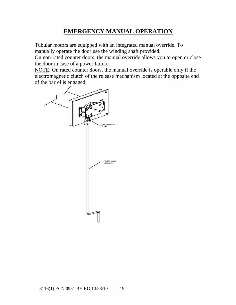
EMERGENCY MANUAL OPERATION
Tubular motors are equipped with an integrated manual override. Tomanually operate the door use the winding shaft provided.On non-rated counter doors, the manual override allows you to open or closethe door in case of a power failure.NOTE: On rated counter doors, the manual override is operable only if theelectromagnetic clutch of the release mechanism located at the opposite endof the barrel is engaged.

3116(1) ECN 0951 BY RG 10/28/10 - 20 -
SAFETY INSTRUCTIONS
WARNING – To reduce the risk of severe injury or death:
1. Read and follow all instructions.
2. Never let children operate or play with door controls.
3. Personnel should keep away from a door in motion and keep the movingdoor in sight until it is completely closed or open. NO PERSON SHOULDCROSS THE PATH OF A MOVING DOOR.
4. Test the door’s safety features at least once a month. Re-adjust travellimits if necessary. Failure to adjust the operator properly may cause severeinjury or death.
5. Save these instructions for reference.

3116(1) ECN 0951 BY RG 10/28/10 - 21 -
MAINTENANCE INSTRUCTIONS
WARNING – Disconnect power supply to the operator before servicing.
1. Inspect and service whenever a malfunction of either door or operator isobserved or suspected.
2. Before servicing, always disconnect power supply to the operator.
3. All replacement parts must be compatible with those originally provided.
4. If an entrapment protection device is used, i.e. sensing edge, pleaseconsult the manufacturer for maintenance instruction.
WARNING – Do not place hands or tools in or near the operator whenthe power is connected or when testing control or safety devices. Alwaysdisconnect power before servicing the operator.