conveyor belt misalignment switch type mrs 001 · conveyor belt misalignment switch type mrs 001. 2...
TRANSCRIPT
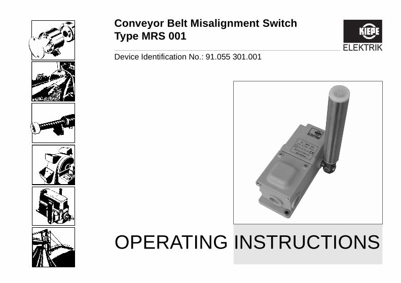
Device Identification No.: 91.055 301.001
OPERATING INSTRUCTIONS
Conveyor Belt Misalignment SwitchType MRS 001
2
MRS 001 Operating Instructions
CE-Sign and Conformity
The device meets the requirements of the validEuropean and national regulations.Conformity has been proved, and the correspondingdeclarations and documents are deposited at themanufacturer.
3
MRS 001 Operating Instructions
Table of Contents
.................................................5............................................................5............................................................5
.................................................6............................................................6............................................................6............................................................6
.................................................7
.................................................8............................................................8............................................................9
...............................................10..........................................................10..........................................................10..........................................................10..........................................................12
..........................................................13
Table of Contents
1 For your own Safety.......................................1.1 Intended Application.......................................................1.2 Symbols..........................................................................
2 Transport, Packing, Storage, and Disposal.2.1 Transport and Packing ...................................................2.2 Storage...........................................................................2.3 Disposal..........................................................................
3 Design and Function......................................
4 Technical Data................................................4.1 General Technical Data..................................................4.2 Dimensions.....................................................................
5 Mounting and Dismounting...........................5.1 Scope of Delivery ...........................................................5.2 Mounting.........................................................................5.2.1 Mechanical Mounting .....................................................5.2.2 Electrical Connection......................................................
5.3 Dismounting ...................................................................
������������
�������
�����
4
MRS
Table of Contents
...................................... 14
...................................... 14
001 Operating Instructions
6 Maintenance and Repair ........................................
7 Ordering Devices ....................................................
5
MRS 001 Operating Instructions
1 For your own Safety
al attention to the text passages thate following symbols:
n that must be observed under allnces in order to prevent the opera-eing injured.
n that must be observed in ordert damage to the device.
ditional information.
1 For your own Safety
1.1 Intended ApplicationConveyor belt misalignment switches of type MRS 001are installed in conveying systems for monitoring the off-track running of continuously running belt conveyors.They serve to protect the belts from damage ordestruction in case of an off-track running.Applications other than specified and unauthorized mod-ifications to the device or its components may lead to in-jury to persons and damage to the device for which themanufacturer is not liable.„Intended Application“ particularly means that any workperformed with the device or on the device must becarried out in accordance with these operatinginstructions. Only qualified personnel that are familiarwith the regulations for the prevention of accidentsas well as the standard safety rules, are allowed to workon the device.This will ensure that you protect yourself andprevent damage to the device!
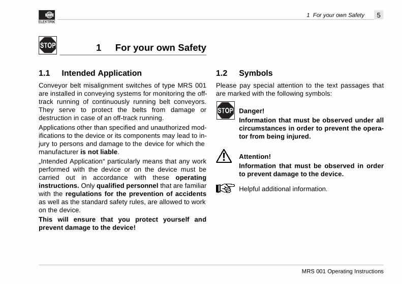
1.2 SymbolsPlease pay speciare marked with th
Danger!Informatiocircumstator from b
Attention!Informatioto preven
Helpful ad
6
MRS
2 Transport, Packing, Storage, and Disposal
sal
2.1Choto tor cgreandpre
2.2AvocaumigTheto +
cking material or dispose of itndly way.
s and components to KIEPE recycling or disposal (forar cover).
001 Operating Instructions
2 Transport, Packing, Storage, and Dispo
Transport and Packingose a suitable packing in order to prevent damage
he device during transport or when sending devicesomponents to KIEPE ELEKTRIK for repair. Take
at care that the device is protected against shocks humidity. Thus, damage due to transport isvented, for which the manufacturer is not liable.
Storageid significant variations in temperature that mayse the formation of condensation water, because thisht damage the device. permissible storage temperature is between -40°C80°C.
Attention!Keep the device clean and dry.
2.3 DisposalIf possible, reuse the pain an environmentally frieSend defective deviceELEKTRIK for correctcompany address see re
7
MRS 001 Operating Instructions
3 Design and Function
ent switch type MRS 001
10° 10°25° 25°
3 Design and Function
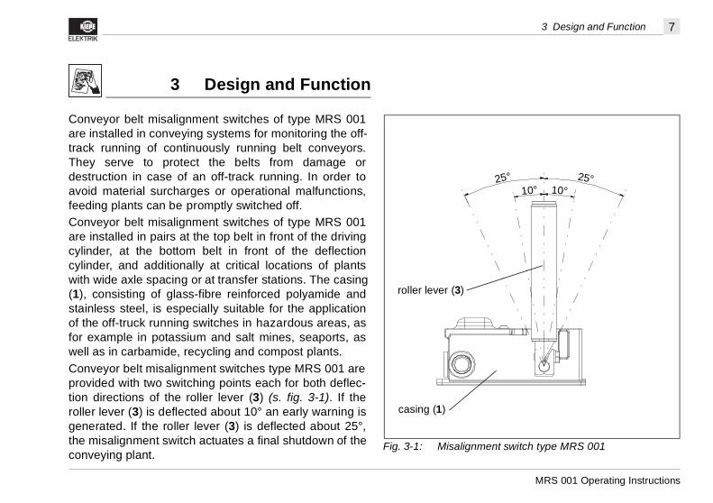
Conveyor belt misalignment switches of type MRS 001are installed in conveying systems for monitoring the off-track running of continuously running belt conveyors.They serve to protect the belts from damage ordestruction in case of an off-track running. In order toavoid material surcharges or operational malfunctions,feeding plants can be promptly switched off.Conveyor belt misalignment switches of type MRS 001are installed in pairs at the top belt in front of the drivingcylinder, at the bottom belt in front of the deflectioncylinder, and additionally at critical locations of plantswith wide axle spacing or at transfer stations. The casing(1), consisting of glass-fibre reinforced polyamide andstainless steel, is especially suitable for the applicationof the off-truck running switches in hazardous areas, asfor example in potassium and salt mines, seaports, aswell as in carbamide, recycling and compost plants.Conveyor belt misalignment switches type MRS 001 areprovided with two switching points each for both deflec-tion directions of the roller lever (3) (s. fig. 3-1). If theroller lever (3) is deflected about 10° an early warning isgenerated. If the roller lever (3) is deflected about 25°,the misalignment switch actuates a final shutdown of theconveying plant.
Fig. 3-1: Misalignm
casing (1)
roller lever (3)
8
MRS
4 Technical Data
4.1
�������
����
�����
ENVD
d switch elementsinal voltage of up to 1,000 V
Su ine safety, electrical equipment of
Ca ), UV and ozone resistant
Fa
Pe
Sw
Sw
Pe
Pe
Co
SwACDC
Pro 9)
Su
Cro
We
001 Operating Instructions
4 Technical Data
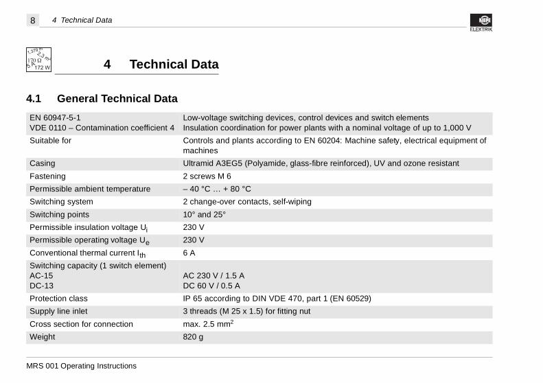
General Technical Data
�����
���
60947-5-1E 0110 – Contamination coefficient 4
Low-voltage switching devices, control devices anInsulation coordination for power plants with a nom
itable for Controls and plants according to EN 60204: Machmachines
sing Ultramid A3EG5 (Polyamide, glass-fibre reinforced
stening 2 screws M 6
rmissible ambient temperature – 40 °C … + 80 °C
itching system 2 change-over contacts, self-wiping
itching points 10° and 25°
rmissible insulation voltage Ui 230 V
rmissible operating voltage Ue 230 V
nventional thermal current Ith 6 A
itching capacity (1 switch element)-15-13
AC 230 V / 1.5 ADC 60 V / 0.5 A
tection class IP 65 according to DIN VDE 470, part 1 (EN 6052
pply line inlet 3 threads (M 25 x 1.5) for fitting nut
ss section for connection max. 2.5 mm2
ight 820 g
9
MRS 001 Operating Instructions
4 Technical Data
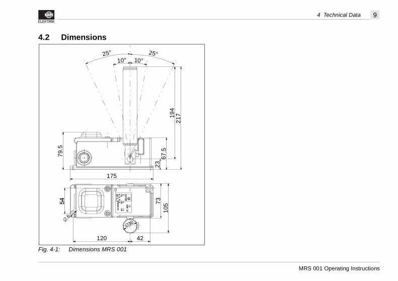
4.2 Dimensions
Fig. 4-1: Dimensions MRS 001
42120
175
10° 10°25° 25°
2367
.5
21719
4
79.5
5454
∅ 6
∅30
7310
5
10
MRS
5 Mounting and Dismounting
5.1Thearethe of d
5.2
nting
alignment switch in such adge of the off-track runninge roller lever (3) in the lowerr. This prevents the belt from roller lever (3) (s. fig. 5-1).
isalignment switch on the conveyor
elt of or
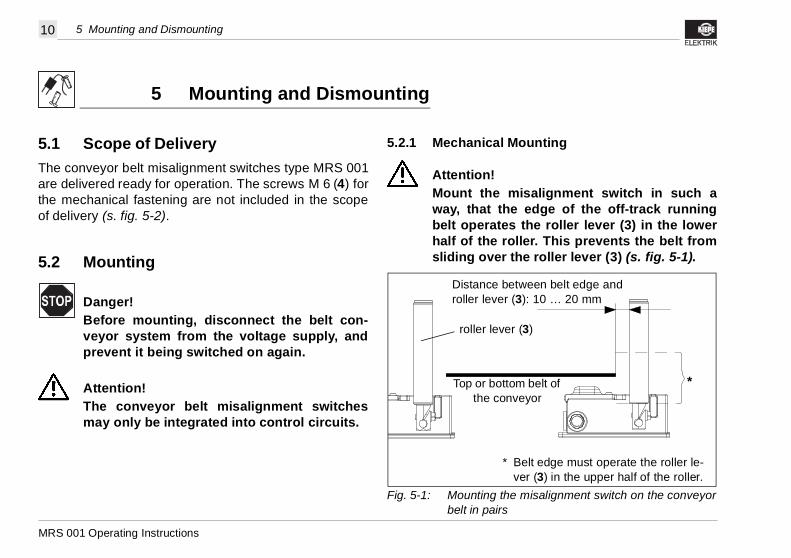
t edge must operate the roller le- (3) in the upper half of the roller.
en belt edge and 10 … 20 mm
*
001 Operating Instructions
5 Mounting and Dismounting
Scope of Delivery conveyor belt misalignment switches type MRS 001 delivered ready for operation. The screws M 6 (4) formechanical fastening are not included in the scopeelivery (s. fig. 5-2).
Mounting
Danger!Before mounting, disconnect the belt con-veyor system from the voltage supply, andprevent it being switched on again.
Attention!The conveyor belt misalignment switchesmay only be integrated into control circuits.
5.2.1 Mechanical Mou
Attention!Mount the misway, that the ebelt operates thhalf of the rollesliding over the
Fig. 5-1: Mounting the mbelt in pairs
Top or bottom bthe convey
roller lever (3)
* Belver
Distance betweroller lever (3):
11
MRS 001 Operating Instructions
5 Mounting and Dismounting
xagonal head screw (9) by means ofrench SW 13 (s. fig. 5-2).
t a fast wear and tear of the roller leverr (3) should be aligned approx. 10 tohe belt edge (s. fig. 5-1 and 5-2).r lever (3) into the required position,he hexagonal head screw (9).
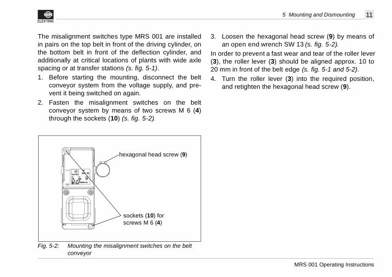
The misalignment switches type MRS 001 are installedin pairs on the top belt in front of the driving cylinder, onthe bottom belt in front of the deflection cylinder, andadditionally at critical locations of plants with wide axlespacing or at transfer stations (s. fig. 5-1). 1. Before starting the mounting, disconnect the belt
conveyor system from the voltage supply, and pre-vent it being switched on again.
2. Fasten the misalignment switches on the beltconveyor system by means of two screws M 6 (4)through the sockets (10) (s. fig. 5-2).
3. Loosen the hean open end w
In order to preven(3), the roller leve20 mm in front of t4. Turn the rolle
and retighten t
Fig. 5-2: Mounting the misalignment switches on the belt conveyor
hexagonal head screw (9)
sockets (10) for screws M 6 (4)
12
MRS
5 Mounting and Dismounting
5.2.
1.
2.
3.
over (2) of the misalignmenthe two screws (5) (s. fig. 5-4).able through the fitting nut (6)
the connector strips (7) accord- diagram (s. fig. 5-5).over (2) of the misalignmentthe two screws (5) (s. fig. 5-4).
Fig. smounting
Thread (M 25 x 15) for a fitting nut (6)
socket (10) for screws M 6 (4)
001 Operating Instructions
2 Electrical Connection
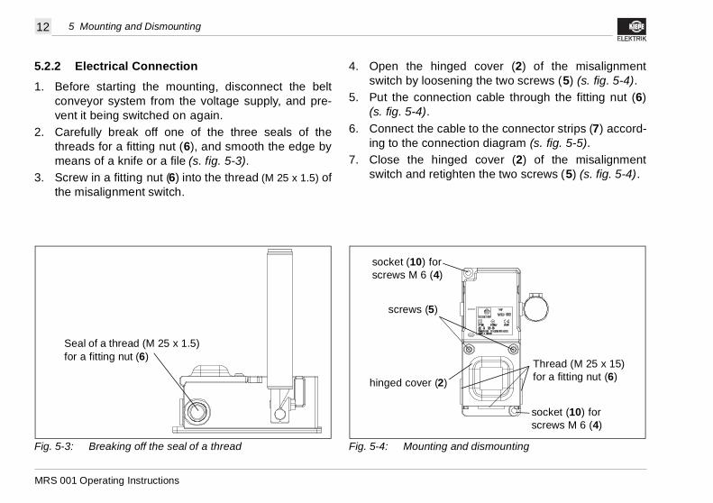
Before starting the mounting, disconnect the beltconveyor system from the voltage supply, and pre-vent it being switched on again.Carefully break off one of the three seals of thethreads for a fitting nut (6), and smooth the edge bymeans of a knife or a file (s. fig. 5-3).Screw in a fitting nut (6) into the thread (M 25 x 1.5) ofthe misalignment switch.
4. Open the hinged cswitch by loosening t
5. Put the connection c(s. fig. 5-4).
6. Connect the cable toing to the connection
7. Close the hinged cswitch and retighten
5-3: Breaking off the seal of a thread
Seal of a thread (M 25 x 1.5) for a fitting nut (6)
Fig. 5-4: Mounting and di
hinged cover (2)
screws (5)
socket (10) for screws M 6 (4)
13
MRS 001 Operating Instructions
5 Mounting and Dismounting
itting nut (6) and pull the connectione misalignment switch (s. fig. 5-4).o screws M 6 (4), and remove the mis-ch (s. fig. 5-4).
5.3 Dismounting
Danger!Before dismounting, disconnect the belt con-veyor system from the voltage supply, andprevent it being switched on again.
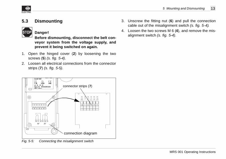
1. Open the hinged cover (2) by loosening the twoscrews (5) (s. fig. 5-4).
2. Loosen all electrical connections from the connectorstrips (7) (s. fig. 5-5).
3. Unscrew the fcable out of th
4. Loosen the twalignment swit
Fig. 5-5: Connecting the misalignment switch
10 11 12 13 14 1510° 25°
connection diagram
connector strips (7)
14
MRS
6 Maintenance and Repair
TheareDefdisp
Witdre1.
2.
001 Operating Instructions
6 Maintenance and Repair
conveyor belt misalignment switches type MRS 001 maintenance-free.ective devices can be sent to KIEPE ELEKTRIK forosal (company address see rear cover).
7 Ordering Devices
h every purchase order, please quote (company ad-ss see rear cover):Type designation of the misalignment switch (s. rating plate on the casing lid): MRS 001Device identification number (s. rating plate onthe casing lid): 91.055 301.001

15
MRS 001 Operating Instructions
7 Ordering Devices
KIEPE ELEKTRIK GmbH & Co. KG � Bublitzer Straße 28 � D-40599 DüsseldorfTel.: +49 (0) 211 74 97 – 0 � Fax: +49 (0) 211 74 97 – 300
Internet: http://www.Kiepe-Elektrik.com � E-Mail: [email protected]
Doc
.-Id
ent.-
No.
:E
ditio
n:M
odifi
catio
n In
dex:
Copyright reserved – Subject to changes
94.0
55 9
10.1
9125
.07.
2001
B