conventional heavy oil vent mitigation - one page options list
TRANSCRIPT
Conventional Heavy Oil Vent Mitigation - One Page Options List
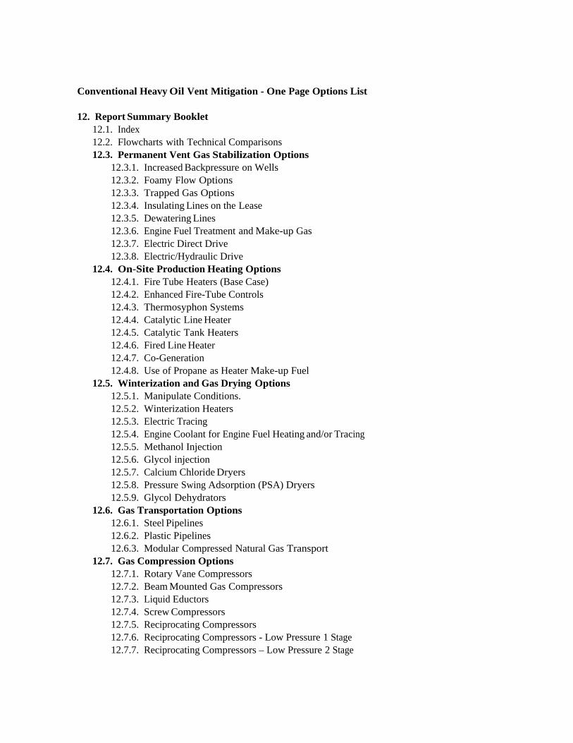
12. Report Summary Booklet12.1. Index12.2. Flowcharts with Technical Comparisons12.3. Permanent Vent Gas Stabilization Options
12.3.1. Increased Backpressure on Wells12.3.2. Foamy Flow Options12.3.3. Trapped Gas Options12.3.4. Insulating Lines on the Lease12.3.5. Dewatering Lines12.3.6. Engine Fuel Treatment and Make-up Gas12.3.7. Electric Direct Drive12.3.8. Electric/Hydraulic Drive
12.4. On-Site Production Heating Options12.4.1. Fire Tube Heaters (Base Case)12.4.2. Enhanced Fire-Tube Controls12.4.3. Thermosyphon Systems12.4.4. Catalytic Line Heater12.4.5. Catalytic Tank Heaters12.4.6. Fired Line Heater12.4.7. Co-Generation12.4.8. Use of Propane as Heater Make-up Fuel
12.5. Winterization and Gas Drying Options12.5.1. Manipulate Conditions.12.5.2. Winterization Heaters12.5.3. Electric Tracing12.5.4. Engine Coolant for Engine Fuel Heating and/or Tracing12.5.5. Methanol Injection12.5.6. Glycol injection12.5.7. Calcium Chloride Dryers12.5.8. Pressure Swing Adsorption (PSA) Dryers12.5.9. Glycol Dehydrators
12.6. Gas Transportation Options12.6.1. Steel Pipelines12.6.2. Plastic Pipelines12.6.3. Modular Compressed Natural Gas Transport
12.7. Gas Compression Options12.7.1. Rotary Vane Compressors12.7.2. Beam Mounted Gas Compressors12.7.3. Liquid Eductors12.7.4. Screw Compressors12.7.5. Reciprocating Compressors12.7.6. Reciprocating Compressors - Low Pressure 1 Stage12.7.7. Reciprocating Compressors – Low Pressure 2 Stage

12.7.8. Reciprocating Compressors – Single Stage Booster12.7.9. Reciprocating Compressor – High Pressure Sales
12.8. Power and Cogeneration Options12.8.1. Thermoelectric Generation12.8.2. Thermoelectric Cogeneration12.8.3. Microturbines12.8.4. Microtrubine Cogeneration12.8.5. Reciprocating Engine Gensets12.8.6. Reciprocating Engine Cogeneration12.8.7. Gas Turbine Gensets12.8.8. Gas Turbine Cogeneration12.8.9. Fuel Cells and Combinations
12.9. EOR Options12.9.1. Methane Reinjection12.9.2. Hot Water Injection12.9.3. Conventional Steam Injection12.9.4. Flue Gas Injection Steam Generator12.9.5. CO2/Nitrogen Injection12.9.6. Methane, Steam and/or CO2/Nitrogen Pressure Cycling12.9.7. Other Combinations of EOR Methods
12.10. Methane Conversion Options12.10.1. Increase Use of Surplus of Casing12.10.2. Flare Stacks12.10.3. Enclosed Flares12.10.4. Catalytic Converters
12.11. Odour Mitigation Options12.11.1. Vapour Recovery12.11.2. Tank Vent Condenser12.11.3. Incinerate in Firetube12.11.4. Catalytic Conversion12.11.5. Dispersion12.11.6. Liquid Contacting12.11.7. Activated Carbon Absorption

Production for Site: Vent Gas Rate (m3/d) Oil Rate (m3/d) Water Rate (m3/d)
Equipment at Site: Propane or Gas Line Power line Tank Pump Drive Engine Other
Calculate On-SiteEnergy Demand for: 1) Tank Heating 2) Artificial Lift
Calculate On-SiteEnergy Available: 1) Vent Gas Energy
Assess & Implement EnergyDisplacement Options
(Low Capital with RapidPayout)
Assess Location FactorsRelative to Energy
Outlets, Area EnergyDemands and Energy
Transport
Flowchart 1 - Current Situation Assessment Flowchart
Permanent Equipment: Pump Drives Casing Gas for Pump Drives Production Heating/Burners Piping and Insulation
Relocateable Equipment: Casing Gas for Heating Site Power Generation Supplemental Heating Short-term intersite transfer
Flowchart 4
Flowchart 2
Flowchart 3
Compression
Current Overall EnergyBalance for the Area and
Individual Sites
Location Factors: Production Pipelines Gas Pipelines Power Lines (25 kVa) Pad or single well Energy deficit sites Other energy outlets
Tool: A. Case Study Tool
Tool: B. Fuel DisplacementOptions Tool
Flowchart 7
Flowchart 6
Flowchart 5PowerGeneration
EOR Facilities
Tool: C. Managed OptionsCase Study Tool
Casing gasvolume remaining small
or highly variable?
Yes
No
Stop -ReviewAgain If
ConditionsChange
Assess Managed EquipmentOptions: Compressors Power Generators EOR Facilities
Permanent or RelocateableEquipment: Power Lines Pipelines Other Energy TransportOptions
Tool: D. Managed Options Tool
What type ofManaged System(s)
Most Attractive?
High Level Comparison of Options
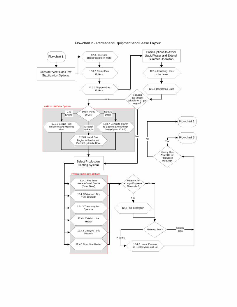
Flowchart 2 - Permanent Equipment and Lease Layout
Flowchart 1
Flowchart 3Yes
Casing GasAvailable forProductionHeating?
No
Flowchart 1
12.4.4 Catalytic LineHeater
12.4.1 Fire TubeHeaters On/off Control
(Base Case)
12.4.3 ThermosyphonSystems
12.4.6 Fired Line Heater
Select ProductionHeating System
12.4.2 Enhanced FireTube Controls
12.4.5 Catalytic TankHeaters
12.4.7 Co-generation
12.4.8 Use of Propaneas Heater Make-up Fuel
12.3.2 Foamy FlowOptions
12.3.1 IncreaseBackpressure on Wells
12.3.3 Trapped GasOptions
12.3.5 Dewatering Lines
12.3.4 Insulating LIneson the Lease
Consider Vent Gas FlowStabilization Options
Basic Options to AvoidLiquid Water and Extend
Summer Operation
12.3.7 Generate Powerto Backout Line Energy
Cost (Option 12.8.5)
12.3.6 Engine FuelTreatment and Make-up
Gas
ElectricDirect
Yes
Select PumpDrive?
Is casinggas supply
suitable for a gasengine?
12.3.8 Install GasEngine in Parallel withElectric/Hydraulic Drive
GasEngine
Electric/Hydraulic
Potential fora Large Engine or
Generator?
Make-up Fuel?
Yes
No
Propane
NaturalGas
No
Production Heating Options
Artificial Lift Drive Options

Flowchart 3 - Relocateable Equipment and Operating
Flowchart 2
12.5.2 WinterizationHeaters
Year-roundOperation?
12.5.3 Electric Tracing
12.5.5 MethanolInjection
12.5.7 CaCl Dryers forCasing Gas
>150 kPaRequired for Main
Heater?
No
Demand vs. Casing Gas
Supply
Demand > Supply
Demand < Supply Can TankTemperature be
Lowered?
No
Vent Pressure>150 kPaReduces
Production?
Yes
Yes
12.5.4 Engine CoolantTracing
Yes
Flowchart 1
Install, Insulate 12.3.4and Dewater 12.3.5Fuel Gas Lines to
Production Heaters
12.5.1 ManipulateConditions
No
No
Add Blending Manifoldto Heater Fuel Supply
Lower Tank Temperature toMatch Gas Available
12.7.5 ReciprocatingCompressors
12.7.2 Beam MountedGas Compressors
12.7.1 Rotary VaneCompressors
Yes
Individual Site Winterization Options
Individual Site Compression Options

Flowchart 4 - Managed Equipment Gas Compression
Flowcharts1, 5 or 6
12.7.6 ReciprocatingCompressor LP 1 Stage
12.7.4 ScrewCompressor
12.7.2 Beam MountedGas Compressor
12.7.3 Liquid Eductors
Is a Pipelinesystem in placebetwen source
sites?
Yes
No
12.6.1 SteelPipelines
Low PressureNetwork or High
Pressure
Low Pressure Network (<350 kPa)
HighPressure
Is gas surplusto area need still
available?
Install High Pressure Pipelineand Metering to Sales Point
No
Assess GasTransportation Options
12.6.3 ModularCompressed NG
Transport
12.6.2 PlasticPipelines
Assess Local Well NetworkGas Compression Options
12.7.1 Rotary VaneCompressor
12.5.7 Calcium ChlorideDryers
12.5.6 Glycol Injection
12.5.5 MethanolInjection
12.5.1 ManipulateConditions
12.5.9 GlycolDehydrators
12.5.8 Pressure SwingAdsorption Dryers
Assess Local Well NetworkFreeze Protection Options
12.3.1 Increased BackPressure on Wells
Redistribute Gas ThroughNetwork with Surplus
Available at a Central Site
Is Surplus Gasto be Sent to Sales?
Flowcharts5 or 6
Yes
Flowchart 1
No
Yes
Assess Dehydration Optionsto Meet Water Content Spec
12.5.7 Calcium ChlorideDryers
12.7.9 ReciprocatingCompressor
High Pressure Sales
12.7.8 ReciprocatingCompressor
1 Stage Booster
12.7.7 ReciprocatingCompressor LP 2 Stage
12.7.2 Beam MountedGas Compressor
Assess Compression Optionsto Meet Pressure
Requirements
Pipeline Freeze Protection Options
Low Pressure Transfer Options
Higher Pressure Compression Options
Gas Dehydration Options
Gas Transport Options
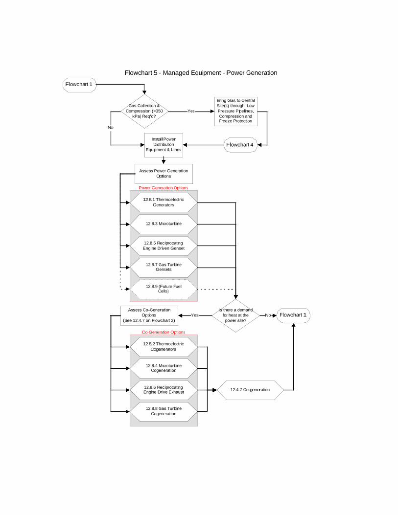
Flowchart 5 - Managed Equipment - Power Generation
12.8.5 ReciprocatingEngine Driven Genset
12.8.3 Microturbine
Flowchart 1
12.8.7 Gas TurbineGensets
12.8.1 ThermoelectricGenerators
Gas Collection &Compression (<350
kPa) Req'd?
Bring Gas to CentralSite(s) through LowPressure Pipelines,Compression andFreeze Protection
Yes
Flowchart 4
No
12.8.9 (Future FuelCells)
Is there a demandfor heat at thepower site?
12.8.2 ThermoelectricCogenerators
12.8.6 ReciprocatingEngine Drive Exhaust
12.8.4 MicroturbineCogeneration
12.8.8 Gas TurbineCogeneration
Flowchart 1No
Install PowerDistribution
Equipment & Lines
Assess Power GenerationOptions
Assess Co-GenerationOptions
(See 12.4.7 on Flowchart 2)Yes
12.4.7 Co-generation
Power Generation Options
Co-Generation Options

Flowchart 6 - Managed Equipment - EOR Options
Flowchart 1
Multiple or SingleWells Available
Single Well
Vertical
Horizontal
Multiple
12.9.3Conventional
Steam Injection
12.9.5 CO2/Nitrogen Injection
12.9.6 Injection -Pressure Cycling
12.9.2 Hot WaterInjection
12.9.1 MethaneReinjection
12.9.7 OtherCombinations
12.9.4 Flue GasInjection Steam
Generator
Flowchart 1
Gas Collection &Compression (<350
kPa) Req'd?
Bring Gas to EORSite(s) through LowPressure Pipelines,Compression andFreeze Protection
Yes
Flowchart 4No
Consider Options forToe <--> Heel to Allow
Production While Injecting
Redrill or Drill New Injector toAllow Production While
Injecting
Assess EOR Flood Options
EOR/Enhancement Options
YesEconomics forRedrill or New
Injectorl?
Horizontal orVertical Well?
No
Casing GasAvailable from
Other Sources?Yes
No

Is there anOdour Problem at
the Site?
12.11.4 CatalyticConversion
12.11.7 ActivatedCarbon Adsorption
12.11.5 Dispersion
12.11.3 Incinerate inFire Tube
Assess MethaneConversion Options for
Remaining Vent Gas
12.10.1 Increase Use ofSurplus Casing Gas
12.10.4 CatalyticConverters
12.10.3 Enclosed Flare
Vent to Atmosphere(Base Case)
Flowchart 1
Flowchart 7 - Methane Conversion and Odour Mitigation
No
Yes
Flowchart 1
12.10.2 Flare Stack
12.11.1 VapourRecovery
12.11.2 Tank VentCondenser
12.11.6 LiquidContacting
Assess Odour MitigationOptions
Methane Conversion Options
Odour Mitigation Options

11.4.2 Technical Comparison Tools
On the Vent Gas option flowcharts there are situations highlighted where there are a number oftechnically viable options, which may or may not also be economically viable. Even where theeconomics are the same there may be technical or operational reasons to select one system overanother in a given situation. In this section we are including technical comparisons of groupedoptions to help highlight issues that should be considered when attempting to decide whichoption is most likely to work best for a given situation. Many of the comments are subjectiveand may not be valid in all situations.
For the High Level Comparison of Options the technical comparison is in the form of Pro’s andCon’s of the main strategic options.
For other option groupings the basic process is to highlight the key selection factors for each setof grouped options, describe why it was felt those factors were important and then generate atable comparing the options in each group against the key selection factors.
Not all comparisons w ere subjected to the same extent of analysis as those groupings, which arefelt to address less common situations, are given less attention.
The option grouping, Technical Comparison Tools, are contained in Section 11.4.2 as follows:
Flowchart 1 – Current Situation Assessment• 11.4.2.1 - High Level Comparison of Options
Flowchart 2 – Permanent Equipment and Lease Layout• 11.4.2.2 - Artificial Lift Drive Options• 11.4.2.3 – Production Heating Options
Flowchart 3 – Relocateable Equipment and Operating• 11.4.2.4 – Individual Site Compression Options• 11.4.2.5 – Individual Site Winterization Options
Flowchart 4 – Managed Equipment Gas Compression• 11.4.2.6 – Gas Transport Options• 11.4.2.7 – Low Pressure Transfer Options• 11.4.2.8 – Pipeline Freeze Protection Options• 11.4.2.9 – Gas Dehydration Options• 11.4.2.10 – Higher Pressure Compression Options
Flowchart 5 – Managed Equipment Power Generation• 11.4.2.11 – Power Generation and Cogeneration Options
Flowchart 6 – Managed Equipment EOR Options• 11.4.2.12 – EOR/Enhancement Options
Flowchart 7 – Methane Conversion and Odour Mitigation• 11.4.2.13 – Odour Mitigation Options• 11.4.2.14 – Methane Conversion Options

11.4.2.1 – High Level Comparison of OptionsHigh Level Option Pro’s Con’s
Purchased Energy DisplacementKey Drivers:• Supply/demand balance• Best economics where supply and demand are
high.
• Economic prize is known from existingenergy costs
• Purchased energy is obtained at a premium• Generally the supply and demand of energy is
proportional to the production.• Generally lowest capital cost options• Quickest payout• Little if any third party involvement.• Likely no royalty implications for use of gas.
• Must be implemented at every producing site.• Solutions need to be simple.• Solutions need to be easy to retrofit.• Short well life requires high portability.
Compressed GasKey Driver:• Close to a sales pipeline. ($30k - $60k/km) for
high pressure lines is a major variable.• Delivery pressure required for sales.• Price received for gas.• Best economics where sources are near a
local, low pressure, gas distribution system
• Economic prize to displace purchased gas isknown.
• Purchased gas is obtained from high pressuresources at a high energy cost, may be additionalcredits for reducing gas moving throughpipelines.
• Third party gas co-ops may be interested inpartnering.
• Many areas have some compression sooperators are familiar with equipment.
• Infrastructure for gas distribution/collectionalready in place in many areas. Current high gasprices may be favourable.
• Payouts may be long compared to other oilproducer opportunities for capital.
• In Saskatchewan gas distribution is regulated• Compression equipment is operator intensive.• Will need to handle gas when compressors are
down.• Will likely require collection of gas to central
sites near sales metering points.• May attract royalties for gas sales.
Power GenerationKey Drivers:• Close to 25 kVa power lines ($20k - $25k/km)
for lines is a major variable cost• Differential between cost of purchased power
vs. the price received for generated power• Best Economics where power can be
displaced and surplus sold at close to marketvalue.
• Economic prize to displace purchased poweris known.
• Purchased energy is obtained at a premium,usually from coal-fired power generation, soadditional GHG credits may be available.
• Potential for co-generation• Third party utilities and independent power
producers are very interested in partnering.• Power distribution infrastructure already in
place in region.• Current shortage of power generation capacity
in the Western Provinces and this region mayincrease the energy value compared to otheroptions.
• Payouts may be long compared to other oilproducer opportunities for capital.
• In Saskatchewan power supply anddistribution is regulated
• In Alberta deregulation process is stillunderway so rules are in a state of flux.
• Power generation equipment will be new tooperators
• Will likely require collection of gas to centralsites near power lines.
• May attract royalties for gas used to generatepower for sale.
EORKey Drivers:
• Turns low value waste stream(s) into highervalue stream (oil).
• EOR impacts will be hard to forecast andquantify even after implementation.

• “Free fuel” for EOR processes so significantstep change in EOR economics.
• Oil production response to EOR method.• Impacts on current wells and other
infrastructure.• Best economics where no new wells are
required and pad scale EOR equipment is used.
• Eliminates known costs of dealing with wastestreams.
• No third party involvement• Likely no royalty implications for gas use,
may be royalty benefit for EOR.• Increased reserves recovery at low cost.• Highest potential for high economic returns.
• Flows for EOR fluids will be based onopportunity not a set plan.
• Requires distributed, portable and flexibleEOR facilities.
• Existing well bores may limit EOR options.(e.g. non-thermal wells, single wells, etc.)
• May create regulatory and approvals problemsdue to short windows of opportunity and need toadapt EOR to available casing gas sources.
Methane ConversionKey Drivers:• Cost of conversion equipment vs. value of
potential credits• Impacts on leases• Best economics are for modular flexible and
low cost units that can be easily retrofitted toexisting leases.
• GHG reduction of 18 tonnes CO2eq per tonneof methane converted.
• Conversion costs should be low and relativelyeasy to verify. I.e. high quality GHG credits.
• Can be used at all venting sites.
• Some methods have poor optics for public(e.g. flaring)
• Some options not viable for low flow orvariable streams.
• No firm guarantee of being able to sellemission credits.
Odour ReductionKey Drivers:• Public concern with odours.• Most economics are intangible benefits to
alleviate concerns about chronic healthproblems. In extreme cases concerns may blockdevelopment of production sites or threatenexisting operations if complaints are not dealtwith.
• Responsible mitigation of concerns willexpedite development approval process.
• Improved relations with neighbours.• Availability of vent gas may significantly
reduce the cost of mitigation of the emission.
• Difficult to obtain information on the problemand assess benefits of mitigation.
• Most solutions at the top of the tank so accessmay be an issue.
• Challenge to design a solution which allowstank to “breathe” and is not likely to be affectedby water vapour and cold temperatures.

11.4.2.2 Artificial Lift Drive Options
To assess the preferred method of utilizing conventional heavy oil vent gas for artificial lift there are a number of key factors to beconsidered, which are:
1. New or Existing Lease - For existing facilities where the decision has already been made between gas and electricity,capital cost to being in the energy source has already been expended. Capital costs for new leases will be heavily influencedby the cost to bring in 25 kva power lines vs. the cost to bring in natural gas or propane as make-up fuel for the periods whencasing gas is expected to be below lease energy demand.
2. Capital Cost – Capital costs will increase with the number of drivers installed.
3. Reliability – Reliability impacts production. Generally systems that can use multiple energy sources in parallel should bemore reliable. The larger the number of systems the greater the reliability as long as switch-over is smooth.
4. Operating Costs – Additional maintenance and control to maintain.
5. Other Uses for Equipment – Can equipment be used for another purpose when not required for artifical lift.
6. Operability Issues – Generally the ease of operation and degree of operator attention for continuous operation isimportant. Directionally a system which is less operator intensive allows more time for operators to perform other duties.
ImpactOnChoice
12.3.6 Engine Fuel Treatment and Make-up Gas 12.3.7 – Generate Power to Backout Line EnergyCost
12.3.8 – Install Gas Engine in Parallel withElectric/Hydraulic Drive
New or ExistingLeases
H • No major difference between new or existingleases. Alternate fuel supply driven by tankheating in most cases.
• Should be relatively easy to retrofit to anexisting lease.
• Power supply lines high cost for new leases.
• May be difficult to locate engine to tie-intohydraulic system unless lease is designed for it.
• Power supply lines high cost for new leases.
Capital Cost H • Low cost to displace purchased fuel gas.Short insulated line from wellhead withregulators and dewatering.
• Cost of generator and fuel lines to matchmotor horsepower.
• Switchgear to automatically switch to linepower fairly standard and inexpensive.
• Cost of engine and hydraulic fluid pump.• Hydraulic and fuel gas tie-ins.• More complex control for automatic
switchover.
Reliability H • Two fuel sources, vent gas or purchasedmaintained for lease tanks, so should be reliable.
• Three energy sources: line power, vent gas orpurchased gas. Outages in any one should beshort.
• Three energy sources; Line power, vent gas orpurchased gas.
• Lower reliability of hydraulic complexhydraulic system may reduce.
OperatingCosts
H • Reduced variable energy costs, no real changefrom using purchased fuel otherwise.
• Significant fixed cost for power lineconnection.
• Increased maintenance for engine.
• Significant fixed cost for power lineconnection.
• Increased maintenance for engine andhydraulic system and controls.
Other Uses ofEquipment
M • No major change from purchased energy. • Power generator could feed power back intogrid if there is surplus capacity or well is down.
• Engine and hydraulic pump could serve as aspare for other sites equipped with engines.
OperabilityIssues
M • No major change from current • More equipment to operate and understand • More equipment to operate and understand

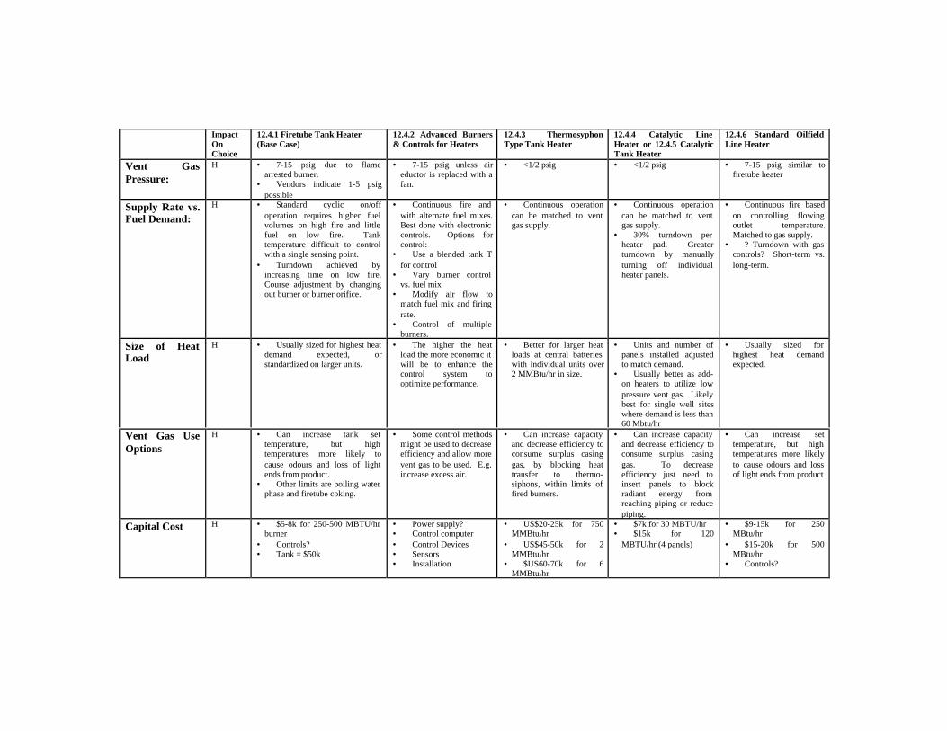
11.4.2.3 Production Heating Options
To assess the preferred method of utilizing conventional heavy oil vent gas for on-site production heating there are a number of keyfactors to be considered, which are:
1. Vent Gas Pressure – Some heaters require higher fuel gas pressures than others. This is a major consideration ifbackpressure on the well annulus cannot be increased and compression is needed to feed the heaters.
2. Supply Rate vs. Fuel Demand – If the supply of vent gas does not match the burner operation then additional purchasedfuel may be required to meet peak demands, which will reduce benefits.
3. Size of the Heat Load – Generally the cost of a heater increases with heater size, however, not all heaters increase in costin the same way or are available in small increments. Also it is known that the heat load required and the vent gasavailable on a lease varies over the life of the well. So the system selected must either be designed for the maximumexpected load, or accommodate expansion of heating capacity with a change in demand on an as needed basis.
4. Vent Gas Use Options – Where there is a surplus amount of vent gas over and above the needs of the lease. A heatingsystem, which can be easily made less efficient with a minimal incremental cost, is an advantage to minimize capital costsand operating effort. This allows the same piece of equipment to serve multiple functions e.g. heating and conversion ofsurplus gas to carbon dioxide.
5. Capital Cost – Needs to be considered from a total cost perspective, rather than just heating. E.g. if a single system canprovide heating and convert surplus methane without requiring additional facilities then that is a preferred option, or ifcosts and constraints of other equipment can be avoided.
6. Operation Adjustment – A system that allows for continuous operation over a wide range of flows and applications is anadvantage.
7. Ability to Handle Foam – If a lease has a tendency to foam, despite the lowered well annulus pressure, then applying heatupstream of the tank should help break down the foam so that it does not build up in the tank which results in loss ofstorage capacity and potential for tank overflows. In tank heating is not as efficient for foam as the foam will not be longin the heated zone.
8. Lease Constraints or Configuration – Lease constraints may make it difficult to modify or change heater systems. Beingable to heat the production near the wellhead avoids having to move the vent gas between the well and the fired heater.Avoiding high temperature combustion in a production heating system would allow the lease to be made smaller.
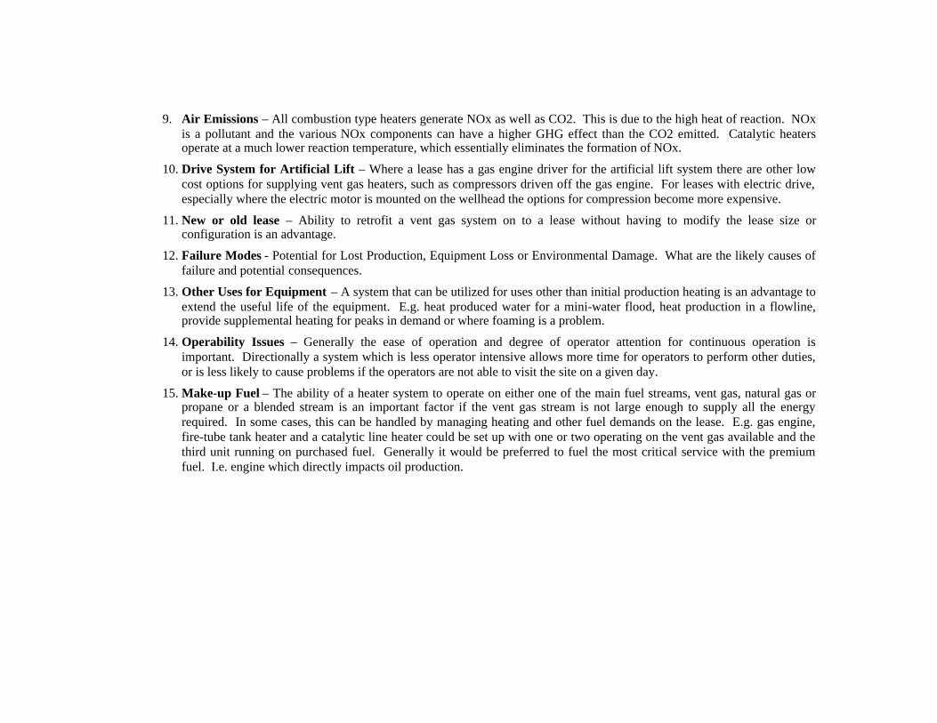
9. Air Emissions – All combustion type heaters generate NOx as well as CO2. This is due to the high heat of reaction. NOxis a pollutant and the various NOx components can have a higher GHG effect than the CO2 emitted. Catalytic heatersoperate at a much lower reaction temperature, which essentially eliminates the formation of NOx.
10. Drive System for Artificial Lift – Where a lease has a gas engine driver for the artificial lift system there are other lowcost options for supplying vent gas heaters, such as compressors driven off the gas engine. For leases with electric drive,especially where the electric motor is mounted on the wellhead the options for compression become more expensive.
11. New or old lease – Ability to retrofit a vent gas system on to a lease without having to modify the lease size orconfiguration is an advantage.
12. Failure Modes - Potential for Lost Production, Equipment Loss or Environmental Damage. What are the likely causes offailure and potential consequences.
13. Other Uses for Equipment – A system that can be utilized for uses other than initial production heating is an advantage toextend the useful life of the equipment. E.g. heat produced water for a mini-water flood, heat production in a flowline,provide supplemental heating for peaks in demand or where foaming is a problem.
14. Operability Issues – Generally the ease of operation and degree of operator attention for continuous operation isimportant. Directionally a system which is less operator intensive allows more time for operators to perform other duties,or is less likely to cause problems if the operators are not able to visit the site on a given day.
15. Make-up Fuel – The ability of a heater system to operate on either one of the main fuel streams, vent gas, natural gas orpropane or a blended stream is an important factor if the vent gas stream is not large enough to supply all the energyrequired. In some cases, this can be handled by managing heating and other fuel demands on the lease. E.g. gas engine,fire-tube tank heater and a catalytic line heater could be set up with one or two operating on the vent gas available and thethird unit running on purchased fuel. Generally it would be preferred to fuel the most critical service with the premiumfuel. I.e. engine which directly impacts oil production.
ImpactOnChoice
12.4.1 Firetube Tank Heater(Base Case)
12.4.2 Advanced Burners& Controls for Heaters
12.4.3 ThermosyphonType Tank Heater
12.4.4 Catalytic LineHeater or 12.4.5 CatalyticTank Heater
12.4.6 Standard OilfieldLine Heater
Vent GasPressure:
H • 7-15 psig due to flamearrested burner.
• Vendors indicate 1-5 psigpossible
• 7-15 psig unless aireductor is replaced with afan.
• <1/2 psig • <1/2 psig • 7-15 psig similar tofiretube heater
Supply Rate vs.Fuel Demand:
H • Standard cyclic on/offoperation requires higher fuelvolumes on high fire and littlefuel on low fire. Tanktemperature difficult to controlwith a single sensing point.
• Turndown achieved byincreasing time on low fire.Course adjustment by changingout burner or burner orifice.
• Continuous fire andwith alternate fuel mixes.Best done with electroniccontrols. Options forcontrol:
• Use a blended tank Tfor control
• Vary burner controlvs. fuel mix
• Modify air flow tomatch fuel mix and firingrate.
• Control of multipleburners.
• Continuous operationcan be matched to ventgas supply.
• Continuous operationcan be matched to ventgas supply.
• 30% turndown perheater pad. Greaterturndown by manuallyturning off individualheater panels.
• Continuous fire basedon controlling flowingoutlet temperature.Matched to gas supply.
• ? Turndown with gascontrols? Short-term vs.long-term.
Size of HeatLoad
H • Usually sized for highest heatdemand expected, orstandardized on larger units.
• The higher the heatload the more economic itwill be to enhance thecontrol system tooptimize performance.
• Better for larger heatloads at central batterieswith individual units over2 MMBtu/hr in size.
• Units and number ofpanels installed adjustedto match demand.
• Usually better as add-on heaters to utilize lowpressure vent gas. Likelybest for single well siteswhere demand is less than60 Mbtu/hr
• Usually sized forhighest heat demandexpected.
Vent Gas UseOptions
H • Can increase tank settemperature, but hightemperatures more likely tocause odours and loss of lightends from product.
• Other limits are boiling waterphase and firetube coking.
• Some control methodsmight be used to decreaseefficiency and allow morevent gas to be used. E.g.increase excess air.
• Can increase capacityand decrease efficiency toconsume surplus casinggas, by blocking heattransfer to thermo-siphons, within limits offired burners.
• Can increase capacityand decrease efficiency toconsume surplus casinggas. To decreaseefficiency just need toinsert panels to blockradiant energy fromreaching piping or reducepiping.
• Can increase settemperature, but hightemperatures more likelyto cause odours and lossof light ends from product
Capital Cost H • $5-8k for 250-500 MBTU/hrburner
• Controls?• Tank = $50k
• Power supply?• Control computer• Control Devices• Sensors• Installation
• US$20-25k for 750MMBtu/hr
• US$45-50k for 2MMBtu/hr
• $US60-70k for 6MMBtu/hr
• $7k for 30 MBTU/hr• $15k for 120
MBTU/hr (4 panels)
• $9-15k for 250MBtu/hr
• $15-20k for 500MBtu/hr
• Controls?

ImpactOnChoice
12.4.1 Firetube Tank Heater(Base Case)
12.4.2 Advanced Burners& Controls for Heaters
12.4.3 ThermosyphonType Tank Heater
12.4.4 Catalytic LineHeater or 12.4.5 CatalyticTank Heater
12.4.6 Standard OilfieldLine Heater
OperationAdjustment
H • Little adjustment. Normallyonly control is temperature set-point and fuel supply orifice.
• Adjustment isdependent on the controlsystem andinstrumentation installedto modify the baseoperation.
• Adjustment isdependent on theburner/control systeminstalled.
• Individual panels canbe manually turned off orrestarted.
• Once in operation asimple thermostaticcontrol can control outlettemperature.
• Adjustment isdependent on theburner/control systeminstalled.
Ability toHandle Foam
H-L • Poor as heat applied inbottom third of tank while foamis above this.
• Little impact is likely. • Poor as heat applied inbottom third of tank whilefoam is above this.
• Lower temperaturegradients result in lessmixing in a standardvertical tank. So may beless able to handle foamthan a standard tnakheater.
• Heats foam upstreamof tank so it breaks down.
• Heats foam upstreamof tank so it breaks down.
LeaseConstraints orConfiguration
M • Tank must be 25m from well. • Controls must meetelectrical requirements.
• Power supply likelyrequired for most controlsystems.
• Must be 25m fromwell.
• Can be locatedanywhere on lease.Lower cost for units thatdon’t have to meet ClassI, Div 1 requirements,which imposes somemoderate limits onlocation or height of unitabove ground.
• May allow reductionin lease size (tankslocated closer to well) iffiretubes eliminated.
• Must be 25m fromwell. Might require largerleases to allow for trucks.
Air Emissions M • NOx emissions. NO is amore powerful GHG thanmethane.
• Some control optionsmay reduce NOxemissions.
• NOx emissions. NOis a more powerful GHGthan methane.
• Little or no productsof combustion other thancarbon dioxide.
• NOx emissions. NOis a more powerful GHGthan methane.
Drive Systemfor ArtificialLift
M • Impacts ability to provide lowcost compression and freezeprotection for use of atmosphericvent gas.
• Gas engine drive preferred.
• Main impact is supplyof reliable power forcontrols. Electric drivepreferred.
• No major impact. • No major impact.Only source of startingpower affected.
• Impacts ability toprovide low costcompression and freezeprotection for use ofatmospheric vent gas.

ImpactOnChoice
12.4.1 Firetube Tank Heater(Base Case)
12.4.2 Advanced Burners& Controls for Heaters
12.4.3 ThermosyphonType Tank Heater
12.4.4 Catalytic LineHeater or 12.4.5 CatalyticTank Heater
12.4.6 Standard OilfieldLine Heater
New or OldLease
M • Already exists on mostexisting leases.
• Adjustment isdependent on theburner/control systeminstalled.
• May be more difficultto retrofit depending onlease layout and spacing.
• Tank modificationsmay be required ifexisting firetube flangescan’t be used.
• Easily retrofitted to anexisting lease and cansupplement tank heater.
• New leasesopportunity to reducelease size.
• May require linemodifications required ifthere are no straightabove ground runs.
• May be difficult toretrofit especially ifheaters must be 25m fromtank and wellhead.Larger leases would berequired and more leasepiping.
Failure Modes M • Fire-tube corrosion orcracking. Failure might result infire. Will result in oil spill on thelease.
• Ignition failures.• Pilot loss due to wind.• Ice build up in flame arrestor
on air inlet.
• Poor as heat applied inbottom third of tank whilefoam is above this.
• Lower temperaturegradients result in lessmixing in a standardvertical tank. So may beless able to handle foamthan a standard tnakheater.
• Loss of ammonia ifheat pipes use this as theheat transfer fluid.
• Ignition failures orexplosions during start-upwould be the most seriousfailures resulting inequipment damage, fireand potential oil spill ifheat pipe entrance flangeto tank is damaged.
• Few working parts.Usual problem might bemechanical damage, fromrigs, vehicles or weather.
• No/low risk ofcatastrophic failures ifoperating guidelinesfollowed.
• Fire-tube corrosion orcracking. Failure mightresult in fire. Will resultin oil spill on the lease.
• Most are indirectheaters with fluid on thetube side. Potentialfailures due to flameimpingement or tube sideoverheating/coking ifflow drops.
• Ignition failures.• Pilot loss due to wind.• Ice build up in flame
arrestor on air inlet.
Other Uses forEquipment
M • Fire-tube could be utilized forcogen production heating.
• Must be 25m fromwell.
• Can be used in heatertreater applications.
• Heat Pipes could beused to transfer cogenenergy to the productiontanks.
• Could also be used toheat water for a mini-waterflood; or as a lineheater for a heated heavyoil flowline.
• Heaters can bereconfigured to directlyheat a tank, warm loadingline, winterize fuel linesor other uses on the lease.
• Could also be used toheat water for a mini-waterflood; or as a lineheater for a heated heavyoil flowline.
• Likely no benefit forco-gen.
OperabilityIssues
M • Susceptible to loss of pilot inhigh winds or cold. So dailyoperator checks are required.
• Heat output and efficiencyeasily adjusted to suit load.
• NOx emissions. NOis a more powerful GHGthan methane.
• ??????? • Usually will only stopif fuel supply is lost.Mostly occurs as a resultof operator action. E.gannulus or flushing.
• Adjustment of heatingwith varying productionlevels difficult.
• Best in steady loadsituations.
Make-up Fuel L • Requires change in orifice toswitch to propane
• No major impact. • ????? • Requires change inorifice and controls toswitch to propane.
• Requires change inorifice to switch topropane

11.4.2.4 Individual Site Compression Options
To assess the preferred method of utilizing conventional heavy oil vent gas for compression and sales there are a number of keyfactors to be considered, which are:
1. Capital Cost – Cost for an equivalent capacity.
2. Operation Adjustment – Ability to change compressor throughput as fuel demand for production heating changes. Rangeof adjustment with a given drive source.
3. Pressure Differential Required – Driven by annulus pressure desired and pressure required for production heatingsystem.
4. Flow Characteristics – How does flow or operating characteristics of the compressor match the characteristics of thedemand.
5. Failure Modes - Potential for Lost Production, Equipment Loss or Environmental Damage. What are the likely causes offailure and potential consequences.
6. Operability Issues – Generally the ease of operation and degree of operator attention for continuous operation isimportant.
7. Ability to Handle Fluids – Relative sensitivity to fluids in the feed gas stream.
ImpactOnChoice
12.7.1 Rotary Vane Compressors 12.7.2 Beam Mounted Gas Compressors 12.7.5 Reciprocating Compressors
Capital Cost H • 25-35 k$ with electric Driver (3.5-35 mscfpd)• Assume 5-15k without motor.
• $11.5 - $16.5k on existing pump jack.Assumes no upgrade required to pumpjack.
• $3-$12k installed without motor (20-50mscfpd)
OperationAdjustment
H • Adjust belt and sheves • Adjust stroke length • Adjust belt and sheves
PressureDifferential
M • 25-30 psig • Up to 50 psig • Up to 50 psig
FlowCharacteristics
M • Constant flow • Periodic flow (10-12 spm) downstreampressure will vary and cause burner controls tocycle.
• Pulsating flow but likely damped out beforeburner.
Failure Modes M • Lost of capacity/pressure due to vane wear. • Failure, seizing of compressor may causefailure of artificial lift drive and lost production.
• Mechanical failure due to liquid slugs
OperabilityIssues
M • Flows need to be checked to determine ifvanes are wearing down
• More difficult to adjust • Greater maintenance
Ability toHandle Fluids
L • Best • Moderate • Poor

11.4.2.5 Individual Site Winterization Options
Assess the preferred method of winterizing sites to allow year-round use of vent gas. Key factors are:
1. Vent Gas Pressure – Is the system sensitive to vent gas pressure.
2. Importance of Insulation and Dewatering – If water forms in the lines can that impact operation.
3. Failure Modes - Potential for Lost Production, Equipment Loss or Environmental Damage. What are the likely causes offailure and potential consequences.
4. Operability Issues – Generally the ease of operation and degree of operator attention for continuous operation isimportant.
5. Operating Costs – On-going costs and time for operators
6. Impact of Fuel Gas Flow – Is operation affected by flow variations
7. Capital Cost – Installed costs for a site. Any economies on larger sites
ImpactOnChoice
12.5.1 ManipulateConditions
12.5.2 WinterizationHeaters
12.5.3 Electric Tracing 12.5.4 Engine CoolantTracing
12.5.5 MethanolInjection
12.5.7 CaCl Dryers forCasing Gas
Vent Gas Pressure H • Yes • No • No • No • L • Yes
Importance ofInsulation andDewatering
H • Very important tomaintain temperatureof gas above dewpoint
• Important so thatheat input is not lost.
• Important so thatheat input is not lost.
• Important so thatheat input is not lost.
• Large impact ondosage required.
• Very importantupstream of dryer.
Failure Modes H • Saturated gascontacts liquid water
• Ambient changes
• Loss of fuel toheater
• Power source fails• Cables overheat.
Potential Fire hazard
• Leaks in lines• Water pump fails• Engine stops
• Injection pumpfailure – loss ofactuation gas/power
• Dryer freezes• Brine isn’t drained
or desiccant refilled
Operability Issues H • Adjustment ofconditions as required.
• Minor - Re-start ifthey go out for manualcontrols.
• Negligible –periodic inspection
• Minor – periodiccheck/top up enginecoolant.
• Minor – periodicrefill of methanoldrum.
• Brine drainingdaily and disposal.
• Refill desiccant
Operating Costs M • Nil. • Nil if casing gasused as fuel.
• Cost of power ifpurchased.
• Minor. • Highly variable • Highly variable
Capital Costs L • Nil for pressurereduction
• Cost of heating iftemperature increased
• $3500 - $4500• Winterization
heater
• $1000 - $1500• Heat tape, power
converter or generatoror transformer
• $200• Tubing and fittings
• $500 - $800 forchemical injectionpump
• $2500 – 5000• Dryer vessel(s)
Impact of Fuel GasFlow
L • Not important forpressure adjustment.
• Heat load fortemperature adjust.
• Continuous flowpreferred.
• Heat load. • Heat load. • Methanolconsumption.
• Desiccantconsumption.

11.4.2.6 Gas Transportation Options
Assess the preferred method of transporting gas between leases. Key factors are:
1. System Pressure – Determines rating of system, degree of water removal required.
2. Capital Cost – Function of materials, installation method and distance.
3. Pressure Losses – Energy used to increase pressure that is lost when pressure is reduced.
4. Other Uses for Equipment – What else might be done with the system in place.
5. Operability Issues – Generally the ease of operation and degree of operator attention for continuous operation isimportant. .
6. Flexibility – Can system be used for more than one use.
7. Failure Modes - Potential for Lost Production, Equipment Loss or Environmental Damage. What are the likely causes offailure and potential consequences.
ImpactOnChoice
12.6.1 Steel Pipelines 12.6.2 Plastic Pipelines 12.6.3 Modular Compressed NG Transport
SystemPressure
H • Preferred for high pressure applications • Preferred for low pressure applications. • Requires high pressures for reasonabletransport.
Capital Cost H • High due to cost of materials and installationmethod.
• Low due to lower cost of materials and abilityto plough in most small sizes.
• High on a per volume basis due tocompression and transport of modules.
• May be of interest to a third party supplier.
Pressure Losses M • Higher pressure loss per km but not significantwith low flows.
• Lower pressure losses • High pressure loss as gas must first becompressed to high pressure then let down.
Other Uses forEquipment
M • Potential to convert to water or heated oiltransfer line as water production increases.
• Potential to convert to water transfer line aswater production increases.
• Lines could be recovered and reused.
• Extend to vehicle refueling for operating area.• System easily portable and moved, no
permanent facilities required.
OperabilityIssues
M • Corrosion monitoring, treatments likelyrequired
• Extremely low temperatures may be an issuefor surface portions of line.
• Modules require to be moved and monitored.• Requires high pressure compression operation
Flexibiility L • Can be used for a wider range of materials andpressures.
• More limited use. • Flexible geographically. Option is not lockedinto a site.
Failure Modes L • Corrosion might be an issue if water, saltand/or oxygen allowed into the system. Leads toleaks.
• Lower ability to handle high pressures • Very high pressures might cause problems onsudden failure of a module.

11.4.2.7 – Low Pressure Transfer Options
Assess the preferred method of transferring gas between sites. Key factors are:
1. Vent Gas Pressure – Differential pressure required to allow gas transfer.
2. Flow Variability – Ability to handle a varying load.
3. Capital Cost – Cost vs. Capacity
4. Operation Adjustment and Issues – Generally the ease of operation and degree of operator attention for continuousoperation is important.
5. Other Uses for Equipment – Flexible use of equipment.
ImpactOnChoice
12.3.1 Increased Back Pressureon Wells
12.7.1 – Rotary VaneCompressor
12.7.2 Beam MountedCompressor
12.7.3 Liquid Eductors 12.7.6 – ReciprocatingCompressor – LP 1 Stage
Vent GasPressure
H • Requires that back pressure issufficient to feed into pipeline.
• 20-30 psig differential. • Compression ratio offour. Atm to 50 psig.
• Can draw a vacuum.Higher vent gas pressurespreferred
• Compression ratio offour. Atm to 50 psig.
FlowVariability
H • Ability to adjust is large if oilproduction is not affected bybackpressure.
• Gas recycle required • Gas recycle required • Limited as operationmainly a function ofpower fluid flow.
• Gas recycle required.
Capital Cost H • Low to nil. • $25-$30k with electricmotor. Higher with gasengine. Lower if artificiallift drive has capacity.
• $11.5 - $16.5k onexisting pump jack.Assumes no upgraderequired to pumpjack.
• US$1500 to US$3500for 3.5 to 35 mscfpd.May need booster pump.
• $16-$24k installedwith electric driver
OperationAdjustment
L • Limited • Change rpm • Adjustabel • Not adjustable unlessdifferential pressure orflow of power fluid canbe changed.
• Change rpm
Other Uses L • Also supports use for fueldisplacement
• Can be used for fueldisplacement
• Can be used for fueldisplacement
• Limited systemsdesigned for anapplication.
• Can be used for fueldisplacement.

11.4.2.8 Pipeline Freeze Protection Options
To assess the preferred method of preventing freezing in a low pressure pipeline. Key factors are:
1. Vent Gas Pressure – Determines amount of water in the gas. Low pressure gas can contain more water.
2. Size of the Load – Chemical required increases with volume.
3. Operating Costs – Ability to adjust operation.
4. Ambient Conditions – What is the impact as ambient temperature drops.
5. Capital Cost – Per site and some allocation from costs at a receiving site
6. Environmental Issues – Impacts on air, health or other issues.
7. Operability Issues – Generally the ease of operation and degree of operator attention for continuous operation isimportant.
ImpactOnChoice
12.5.1 Manipulate Conditions 12.5.5 Methanol Injection 12.5.6 Glycol Injection 12.5.7 Calcium ChlorideDryers
Vent GasPressure
H • Affects dew point andformation of free water
• Affect requireddosage.
• Affects requireddosage.
• Affects desiccantconsumption
Size of theLoad
H • Not important for pressureadjustment.
• Heat load for temperature.
• Affects consumption • Affects volumerecirculated.
• Affects consumption
OperatingCosts
H • Very low. • Methanol $0.4-$0.5/llost to gas.
• Operator time forrefilling and flow adjust
• Fuel for regeneration;some make-up.
• Operator time totransfer glycol to sites.
• CaCl cost $2/lbremoves 3.5 lbs of water.
AmbientConditions
H • More difficult to preventfreezing.
• Consumptionincreases
• Recirculationincreases.
• Consumptionunaffected by ambient.
Capital Cost M • Nil for pressure reduction• Cost of heating method if
temperature increased
• Chemical injectionpump, controls, tank
• $500 - $800
• Pump, separator,reboiler, tank, controls
• $1000-$1500/site
• Dryer vessel(s)• $2500 - $20,000
EnvironmentalEmissions
M • None • Actuation gas vented• Chronic exposure to
methanol hazardous.
• BTX Emissions• Actuation gas for
injection pump
• Brine disposal
Failure Modes L • Saturated gas contacts liquidwater
• Ambient conditions change
• Pump Failure • Pump Failure • Dryer freezes off• Brine isn’t drained or
desiccant refilled.

11.4.2.9 Gas Dehydration Options
Assess the preferred method of dehydrating vent gas for sale. Key factors are:
1. Vent Gas Pressure – Pressure affects size, cost and efficiency of dehydration system.
2. Water Content – Set by negotiation with consumer of the gas.
3. Capital Cost – Function of pressure and capacity.
4. Operating Costs – Cost of consumed materials and operator time.
5. Environmental Emissions – What are air, health and other issues.
6. Operability Issues – Generally the ease of operation and degree of operator attention for continuous operation isimportant.
ImpactOnChoice
12.5.7 Calcium Chloride Dryers 12.5.8 Pressure SwingAdsorption Dryers
12.5.9 Glycol Dehydrators
Vent GasPressure
H • >25 psig for best economics • >150 psig for besteconomics
• High pressurepreferred. Very lowefficiency at low pressure.
Water Content H • Likely uneconomic for salesspec gas.
• Suitable for 4lb/mmscfsales gas spec.
• Suitable for 4lb/mmscfsales gas spec
Capital Cost H • Dryer vessel(s)• $2500 - 20000
• Skid mounted unit• $9-$44
• Regenerator;contactor; lean/rich heatexchanger, pump, surgetank and filter.
• $50+k
OperatingCosts
H • On-going consumption ofCaCl or LiCl. $2/lb for CaCl or$18/lb for LiCl. LiCl requiredfor lower water content.
• Low unless resincontaminated.
• Requires fuel forregneration.
EnvironmentalEmissions
M • Brine disposal. • Purge gas vented. • BTX and methaneemissions fromregenerator vent.
Failure Modes M • Dryer freezes off• Brine not drained/desiccant
refilled.• Fail to meet sales spec.
• Lube oil poisoning.• Fail to meet sales
spec.
• Glycol breakdown• Fail to meet sales spec
OperabilityIssues
M • Time to check and refilldesiccant. Drain on a daily basis
• Monitor operation.Equipment similar to airdryers.
• Monitor Operation.Equipment relativelystandard.

11.4.2.10 Higher Pressure Compression Options
Assess the preferred method of compressing gas for sales. Key factors are:
1. Pressure Differential – Pressure differential required to enter sales system.
2. Capacity – Capacity of the system.
3. Capital Cost – Comparison for a standard volume.
4. Other Uses for Equipment – Can equipment be used elsewhere to some advantage.
5. Operability Issues – Generally the ease of operation and degree of operator attention for continuous operation isimportant.
ImpactOnChoice
12.7.2 Beam Mounted GasCompressor
12.7.4 Screw Compressor 12.7.7 ReciprocatingCompressor LP 2 Stage
12.7.8 ReciprocatingCompressor 1 StageBooster
12.7.9 ReciprocatingCompressor HighPressure Sales
PressureDifferential
H • 50-200 psig • 50-200 psig • 0 to 200 psig • 50-200 psig • 200-800+ psig
Capacity H • Small volumes only <10mscfpd
• > 200 mscfpd • Wide range • Wide range • Not likely viable forvent gas volume alone
Capital Cost H • $11.5-$16.5 plus pumpjackdriver (surplus)
• $55-60k (105 mscfpd)• $95-150k (700
mscfpd) installed
• $60-95k (105 mscfpd)with electric drive. Add$10k for engine.
• $$95-125k (700mscfpd). Add $30k forengine.
• No vendor wouldprovide an estimate.
Other Uses M • Could be used for lowpressure systems
• Limited • Limited • Limited • Limited
Operability L • High level of operatorattention vs. volume compressed.
• Seal oil replacement.• Generally lowest
maintenance cost• Need to control both
inlet and outlet pressure
• High maintenance formulti-stage.
• Moderate maint. • High maintenance

11.4.2.11 Power Generation and Co-Generation Options
Power generation and co-generation options are compared together as there is no option to combine generation and co-generationindependently. For each generation system the matching co-generation option will be considered as a factor in the analysis:
1. Gas Supply Available – Strong factor in deciding which system to use.
2. Capital Cost – Function of type
3. Efficiency (Generation alone and with Co-Gen) – Maximize benefit of gas use.
4. Use for Waste Heat – To take advantage of cogeneration there must be an appropriately sized demand for heat energy onthe power generation site.
5. Other Uses for Equipment – Can be used for power generation with purchased gas, supply more to grid during periods ofhigh power demand.
6. Operability and Operating Cost Issues – Generally the ease of operation and degree of operator attention for continuousoperation is important.
ImpactOnChoice
12.8.1 & 12.8.2 ThermoelectricGenerators
12.8.3 & 12.8.4 Micro-turbine Co-Gen
12.8.5 & 12.8.6 Recipro-cating Engine DrivenGenset
12.8.7 & 12.8.8 GasTurbine Gensets
12.8.9 Fuel Cells
Gas SupplyAvailable
H • 50 scf/d – 1700 scf/d • 10 mscf/d – 20 mscf./d • 15 mscf/d – 850mscf/d
• 400 mscf/d • Requires hydrogenfuel (reforming methane)
Capital Cost(w Co-gen)
H • Modular units• $2570 - $22000• (+$5000)
• $1000 – 1500/kw• $5000 – 10000 for
compression• (+$15000)
• $400 - $600/kw +• Gas line connection,
gas conditioning andcompression
• $1000/MW or lower• Gas line connection,
gas conditioning andcompression
• ($825 – 900k forHRSG)
• $6000/kw
Efficiency (wCo-gen)
H • 5% ( unspecified) • 25 – 30%• (75+%)
• 30-35%• (80%)
• 25-30%• (65-80%)
• 50%• (70%)
On-Site HeatLoad
M • Low on-site. • Moderate demand forheat
• Moderate demand forheat
• High demand for heat • Predicted to be low
Other Uses L • Cathodic protection, remoteSCADA
• Power for sale usingpurchased gas wheneconomics are favourable.
• Power for sale usingpurchased gas wheneconomics are favourable.
• Power for sale usingpurchased gas wheneconomics are favourable.
•
OperatingCosts
L • No moving parts, relativelymaintenance free, run unattendedfor extend periods
• Scheduledmaintenance after 10000hours of operation
• Some consumablessuch a filters
• Maintenance intensiveyet widely available
• 1.5c/kWhr
• Specializedmaintenance but lowfrequency.
• .5c/kWh
• Predicted to be low asoperates like battery withno moving parts
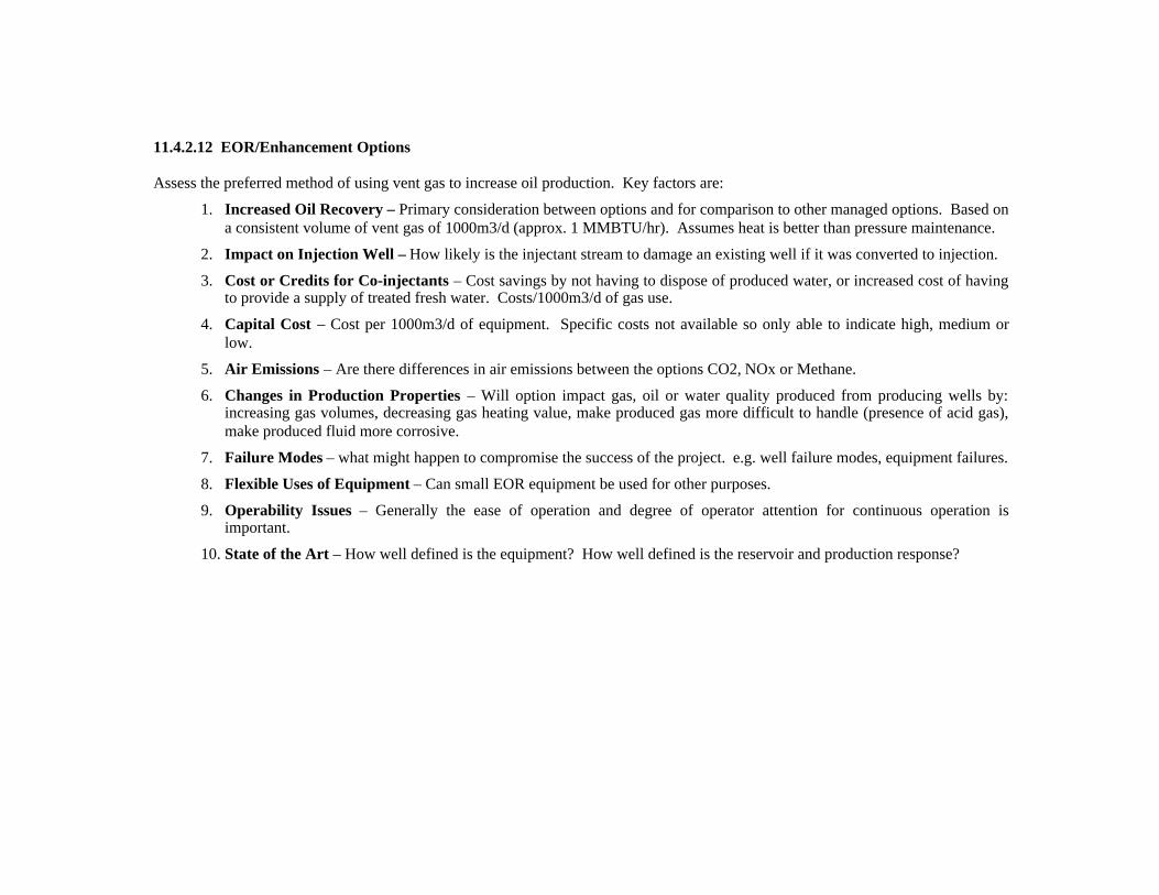
11.4.2.12 EOR/Enhancement Options
Assess the preferred method of using vent gas to increase oil production. Key factors are:
1. Increased Oil Recovery – Primary consideration between options and for comparison to other managed options. Based ona consistent volume of vent gas of 1000m3/d (approx. 1 MMBTU/hr). Assumes heat is better than pressure maintenance.
2. Impact on Injection Well – How likely is the injectant stream to damage an existing well if it was converted to injection.
3. Cost or Credits for Co-injectants – Cost savings by not having to dispose of produced water, or increased cost of havingto provide a supply of treated fresh water. Costs/1000m3/d of gas use.
4. Capital Cost – Cost per 1000m3/d of equipment. Specific costs not available so only able to indicate high, medium orlow.
5. Air Emissions – Are there differences in air emissions between the options CO2, NOx or Methane.
6. Changes in Production Properties – Will option impact gas, oil or water quality produced from producing wells by:increasing gas volumes, decreasing gas heating value, make produced gas more difficult to handle (presence of acid gas),make produced fluid more corrosive.
7. Failure Modes – what might happen to compromise the success of the project. e.g. well failure modes, equipment failures.
8. Flexible Uses of Equipment – Can small EOR equipment be used for other purposes.
9. Operability Issues – Generally the ease of operation and degree of operator attention for continuous operation isimportant.
10. State of the Art – How well defined is the equipment? How well defined is the reservoir and production response?

ImpactOnChoice
12.9.1 Methane Reinjection 12.9.2 Hot Water Injection 12.9.3 Conventional SteamInjection
12.9.4 Flue Gas InjectionSteam Generator
12.9.5 CO2/NitrogenInjection
Increased OilRecovery
H • Poor – 900 m3/d of gas per1000 m3/d of vent gas
• Good – 1 MMBTU/hrof heat added per 1000m3/d of gas
• Good – 1 MMBTu/hrheat added per 1000 m3/d
• Best – Large volumesof gas and heat. Assume8000 m3/d of gas + 15m3/d of steam/1000 m3/d
• Good – Large volumesof gas. Assume 8000m3/d of gas per 1000m3/dof vent gas
Impact onInjection Well
H • Good – Increased pressurestress but lowest of the gasinjection options
• Best – 150-200degrees C, Low Pressures
• Poor – High thermaland pressure stresses oncasing.
• Poor – High thermaland pressure stresses pluscorrosion.
• Poor – Higherpressures than methanealone. Potential forcorrosion.
Capital Costs H • Good – Gas engine and lowvolume, high pressurecompressor.
• Best – Gas enginedriven low pressure pumpand line heater.
• Poor – Steamgenerator, high pressurepumps, water treatment
• Poor fuel gas and aircompression
• Good. Gas engine andcompression highvolume, high pressurecompression.
Failure Modes H • Good. Methane tounintended zone, clean-uprequires depressuring.
• Gas breakthrough toproducers. Potential for highpressure, high flow venting at aproducer causing washouts.
• Best. Water spill oroil carryover to injection.Annulus can be chargedwith pressurized gas.
• Warming productionlikely beneficial
• Poor - High Pressurefresh water steaminjection into surfaceaquifer due to casingfailure.
• Steam breakthroughcould cause producingwell failures. Potentialfor high pressure, highflow venting at a producercausing washouts.
• Poor – High pressurecombustion gases andproduced water intosurface acquifer. Clean-up requires flow back.
• Steam gasbreakthrough could causeproducing well failures.Potential for highpressure, high flowventing at a producercausing washouts.
• Hazards due to highpressure air/oxygen andpotential for oxygenproduction.
• Poor – High pressurecombustion gases intosurface acquifer.
• Gas breakthroughcould result in largevolumes of combustiongases venting at aproducing well. Potentialfor high pressure, highflow venting at a producercausing washouts.
State of the Art H • Best for facilities.Compression and gas injectionstandard operations in otherareas.
• Good for Reservoirs -Pressure maintenance for heavyoil not widely used. Impact of
• Best for facilities.Water heating andpumping standardoperations.
• Best for reservoir –response should bepredicatable, onlyunknown is impact onfoamy flow.
• Good for facilities.Standard equipmentadapted for unattendedoperation.
• Best for Reservoir –thermal steam operationsunderway in area.
• Poor for Facilities –Facilities and equipmentneed to be designed andtested.
• Poor – No experiencein Canada with this typeof injection.
• Good for Facilities –Facilities designed but notusually used forcontinuous operation.
• Good for Reservoir –Nitrogen might be similarto methane, CO2 impactthe main unknown.
OperatingCosts – Co-injectants
M • Good. No co-injectants(neutral)
• Best. Use producedwater save $3500/d if 100m3/d produced waterinjected instead oftrucked.
• Poor. Likely have tohaul in fresh water at rateof 15 m3/d $600/d for1000 m3/d vent gas
• Best. Likely would beable to use producedwater so save truckingcosts, air is free.
• Best. Combustion airis free.
Changes inProductionProperties
M • Good. Increased methaneproduction at some producers ifthere is gas breakthrough.
• Best. Productionmight be a bit warmer.
• Good. Thermalupgrading might generateH2S which might causenew odour and safety
• Poor. Thermalupgrading might causeH2S. Combustionproducts will lower pH,
• Poor. Combustionproducts will lower pH,may cause emulsions andcorrosive fluids, nitrogen
concerns. may cause emulsions andcorrosive fluids, nitrogenand CO2 will dilute gas atproducers if theybreakthrough
and CO2 will dilute gas atproducers if theybreakthrough.
OperabilityIssues
M • Good. Standard operatingissues for compression.
• Best. Simple pumpand heater.
• Good. High pressurepump, water testing andhigh pressure steam.
• Poor. Unknownoperability issues.Hazards of aircompression.
• Good. Should besimilar to compressionoperations.
Air Emissions L • Best. CO2 and NOx fromcombustion of fuel portion only(10% of 1000 m3/d). Eventuallygas produced.
• Best. CO2 and maybeNOx from 1000 m3/d.NOx would not be afactor with catalytic lineheaters.
• Good. CO2 andmaybe NOx from 1000m3/d.
• Best. Combustiongases injected, may besequestered.
• Best. Combustiongases injected, may besequestered.
Flexible Use ofEquipment
L • Compressors can be used forhigh pressure sales.
• Line heaters andpumps can be used inother applications. Forproduction heating,flowline heating, methaneconversion, etc.
• Can be moved to addto capacity at larger sites.
• Fuel compressorsmight be used for gascompressions
• Underbalanceddrilling

11.4.2.13 Odour Mitigation Options
Assessing Odour Mitigation Options is very difficult in this application as there is not indication that it has been a concern or what thesource of the concern would be. The intent is to have options available to try in case complaints occur which require a response tomaintain a site in operation:
1. Capital Cost – Primary driver as this is a low risk situation and volumes involved are very low.
2. Operability Issues – Any odour mitigation in this application is likely to be located at the top of the lease tank. Given lowrisk the best options are those that require little if any operator attention.
ImpactOnChoice
12.11.1 VapourRecovery
12.11.2 Tank VentCondenser
12.11.3 Incinerate inFiretube
12.11.4 CatalyticConversion
12.11.5 Dispersion 12.11.6 LiquidContacting
12.11.7ActivatedCarbonAdsorption
Cost H • Blanket gas supply,dual pressurecontroller, emergencypressure protection,compressor
• $10 – 15k
• Air cooled heatexchanger andsmall separator
• Vent gas line,small flamearrestor, vendorburnermodification
• $1000
• Small heater,wind/weatherbreak, and fuel gastubing
• $3000 - 3500
• Pipingextension off stackor mixing element
• $1000 - 1500
• Contactingvessel, ventgas fan/pump,manual handpump toreplenishsponge oil
• $3000
• Contactingvessel
• $1500
Operability M • Self-regulating• Only if large system
upset.
• Manuallyadjusting amountof cooling runsonline as ambientconditions change
• No change fromcurrent burneroperations.
• Start/re-startheater
• Periodicallycheck operation
• Units damagedif tank overflows
• Requires nooperator attention.
• Top upand/or changeout sponge oilperiodically
• Change outpipe spoolperiodically,potentially treatas hazardouswaste.
• Monitordelta P acrossvessel

11.4.2.14 Methane Conversion Options
To assess the preferred method of utilizing conventional heavy oil vent gas for methane conversion to CO2, there are a number of keyfactors to be considered, which are:
1. Ability to handle long and short-term flow variability over a wide range of flows – The intent is that these systemwould handle whatever vent gas is uneconomic to use from one or more wells. Variability will come from gas firedequipment operation variations, variations in vent gas flow rates, etc.
2. Capital Cost – Must be low cost to be able to show a potential for net revenue gains from GHG credits.
3. Operability – Must be easy to maintain in operation and be self adjusting to handle flowrate changes.
4. Lease Issues – Options may affect lease size required. Visibility issues or the presence of livestock near or on a lease mayaffect the acceptability of the option to landowners in the area.
ImpactOnChoice
12.10.1 Increase Use of SurplusCasing Gas
12.10.2 Flare Stack 12.10.3 Enclosed Flare 12.10.4 CatalyticConverters
HandleVariable Flow
H • 5:1 turndown.• If tank temperature set point
set too high, may not be enoughfuel to meet demand.
• 4:1 – 5:1 turndown,higher for electroniccontrols
• 4:1 – 5:1 turndown,higher for electroniccontrols
• Individual units 1.5:1turndown
• Additional turndownby starting or stoppingadditional heaters.
Capital Cost H • None. • $5000 - $150,000 • $15,000 - $500,000 • $4-5,000 for 72,000BTU/hr panel (12 ft2)
Operability M • Very High• Tank temperature set point
adjustment.
• May be difficult tokeep flame going at lowsurplus gas rates.
• Re-start difficult
• May be difficult tokeep flame going at lowsurplus gas rates.
• Re-start from groundlevel.
• High• Adjust number of
panels turned on.• Re-start only required
if gas flow totallystopped.
Lease Issues M • None. • Visible flame,potentially smoke –potential PR problem.
• 50 m from wellhead orstorage tank, 25 m outsidehazardous area.
• No visible flame orsmoke.
• 50 m from wellhead orstorage tank, 25 m outsidehazardous area
• Can be designed forhazardous areas.
• Silent, flameless,odourless.

Heavy Oil Casing Gas Utilization Option Sheet
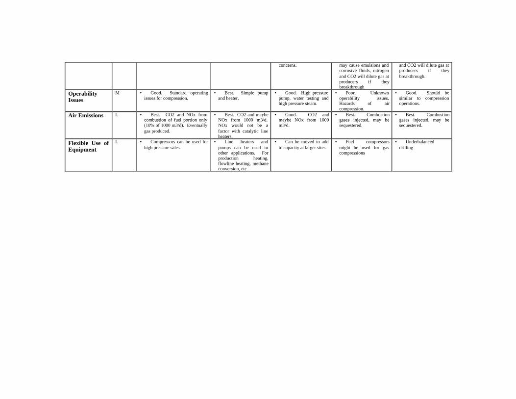
Option 12.3.1: Increased Backpressure on Wells
One of the major problems related to utilization of vent gas is the extremely low well annuluspressures that are maintained on most conventional heavy oil wells. Even 10-15 psi of back-pressure on the wells has been shown, in some cases, to impact well production rates and, as aresult, it is often common practice to maintain low annulus pressures at all times on a routinebasis. When venting to atmosphere this does not necessarily have negative consequences butwith vent gas recovery low pressure venting can add significantly to costs and operatingrequirements. Also, some companies have had experience where production is not affected by15-25 psi of annulus backpressure and others have indicated that in some cases they found thathigher backpressures improve production. The purpose of this option is to indicate options forquickly determining if oil production is affected by small increases in backpressure.
Testing Effect of Backpressure
Well
StorageTank
Monitor Tank Head vs. Time @15-30 minute intervals at accuracyOf +/- 0.1 psi = +/- 0.2 ft of head
Pressure Data Logger
Monitor Casing Vent FlowrateWith Chart Recorder
Monitor Tank Vent(Spot Test)
GenerateStep Change(s)In Backpressure
Production
For any well being assessed for vent gas utilization the well should be tested. The biggestunknown in testing is usually the production volume which is difficult to monitor accurately orfrequently with the normal production measurement methods using tank gauging and trucktickets. The recommended test would consist of at least a 3 day test to minimize operator timeon site and ensure rates are stabilized. Day 1 would monitor the undisturbed current operation;Day 2 would be after a step change has been made in annulus vent back pressure (either bypinching back a manual valve or adjusting a vent pressure regulator); Day 3 would be after astep change back to the original operating conditions as a control. Most of the factors whichmight affect production as a result of a change in annulus pressure should show relatively quickresponse to the operating change. Tank fluid level would be monitored on a frequent basis witha battery powered pressure sensor and datalogger which can be temporarily mounted on the leasestorage tank. The data collected can be used to generate a plot that shows changes in production
rate over time when combined with the lease tank’s characteristic for height of fluid vs. volume.Vent gas rate can also be monitored (using normal orifice and chart recorder kit) to see if the gasrate changes with the change in backpressure. Spot checks might also be made on the tank ventto see if the tank vent gas rate changes.
The tank level monitoring will give an accurate indication of any production rate changes. Thevent gas monitoring will indicate if any gas is being diverted to the tank vent which wouldindicate that a reduction in foam breakdown in the well might be putting more foam through thepump and causing a loss in production. This testing, potentially multiple tests with increasingamounts of backpressure will indicate whether production is actually affected by backpressureand if the cause is the reduction in foam breakdown in the well. (See Option 12.3.2)
Benefits:
If a higher backpressure can be maintained without loss of production, or generation of otherproblems (foam in tanks) then the benefits are:♦ No need for compression or low pressure burners for on-site use♦ No need for compression for low pressure gas transfer.♦ Ability to manipulate conditions for water content to reduce downstream water formation.♦ Potentially increased production from increased understanding of impacts of pressure on
well performance.
Costs:
Testing could be set up as an expansion of the current vent gas testing to allow operators togather data. Pressure monitors could be purchased or rented for this testing which would ideallybe carried out in the summer. Estimated cost to purchase a pressure monitor and data logger$1500.
Limitations:Testing may have to be done at each well depending on the results achieved during initial tests.If foaming is the problem in an area the foam breakdown conditions may vary from well to well.See option 12.3.2

Heavy Oil Casing Gas Utilization Option Sheet
Option 12.3.2: Foamy Flow Options
Foaming is a common production problem. While foam generation in the reservoir cansignificantly increase oil production into the well it can also result in loss of some of the benefitsdue to: a) loss of pumping efficiency, b) loss of effective tank storage capacity on the lease; andrelated problems due to the difficulty of breaking down foam in a storage tank. Another impactis that periodic generation of stable foams in the well can impact the flow of the casing gas, asgas will be diverted with the foam into the tank and eventually exit through the tank vent. Thisoption allows surplus casing gas and produced water from the well to be used to assist in foamsuppression by providing down hole heating and continuous liquid washing.
Foamy Flow - Solution
T=65-80C
Foamy WellT = 20-30 deg CAnnulus Pressure = X (kPa(g))
Check-Valve
h (m)
Small TubingString Down Annulus
Small Tubing String Length (h) = X/10So pressure due to fluid column = X + head in tank
Hot Water down annulus willhelp suppress foam in well.
Well
Storage Tank
Hot Produced Water
The diagram shows how hot water from a lease tank might be gravity fed into the well annulus,even if the annulus is not at atmospheric pressure. The hot water will warm up the foamdownhole and will also wash it which will enhance foam breakdown. Water flow required maybe quite low but testing will be required to gain a better feel for this. Water injected must bepumped again to surface but is not consumed so there would be no net change in productionfrom the well, even though more water is going through the pump. Option to add a line heater tofurther boost the water temperature before it enters the well would allow more energy to reducefoam with less water. Option to add a pump if the well annulus pressure is very high or if, forsome reason the annulus (macaroni) tubing string can’t be used.

Benefits:
Reduce impact of foam on pump efficiency and lost production.♦ Lost pump efficiency♦ Production Restrictions due to problems heating foam in lease tanks♦ Avoid bringing extra tankage brought into lease to handle foam♦ Avoid problems with use of case gas due to variability♦ Save on costs and operator time associated with well “loading” by truck.♦ Increases energy demand for heating on the lease so more casing gas will be used by the
tank heaters, increasing the GHG benefits with little additional cost.♦ Line can also keep casing gas going to tank burner warm.♦ Reduced potential for tank (foam) spills
Costs:
Mainly small tubing and fittings:
Valve below normal water level in storage tank. 25m of _” tubing or pipe installed with andinsulated to production line. Small valves to allow for draining. Valve with packing gland onannulus vent to allow water into the well separate from the venting gas. Check valve to preventreverse flow. Tubing in well and tubing check valve if additional head is needed. May needprotection in case of pump going down to prevent tank water level being drained too low withoutrecirculation. Avoid by ensuring a 2-3 day supply of water in the tank and that line to well isshut-off if well is to be down for more than that length of time. Other mechanisms might be ahydraulic or mechanically actuated valve on the line at the well which would close if the pumpgoes down, or a displacer type shutoff at the tank which would stop water flow if the oil level gottoo low. These devices would add to the cost and would need to be designed for high reliability.
Operations and Maintenance:
The system would be self limiting and can just be turned on when there is a foaming problem.Balance of pump capacity lost to foam vs. incremental pump capacity to recycle a bit of water.Water line should be insulated to the production line but isolated from the line so it is protectedfrom freezing but not losing all its energy to the flowline. Line can be drained to the well whenit is not in use displace with casing gas to avoid corrosion, might use stainless steel tubing.Water is recirculating so no concern about draining tank unless well shutin.
Limitations:Some heat will be transferred to the ground, production and gas in the wellbore so it may takesome time to warm up. Additional work is required to conduct a controlled tests in the field todemonstrate effectiveness. Injecting water in the annulus will have to be monitored to determineif this causes any corrosion problems in the annulus.

Heavy Oil Casing Gas Utilization Option Sheet
Option 12.3.3: Trapped Gas Options
Occasionally wells will show a tendency for vent gas to only flow periodically. This mayindicate that the gas is separating in the reservoir and building up behind the casing. Over someperiod of time the gas pressure will build up to the point where it can force its way into the upperproduction perforations. Once flowing the gas pocket will depressure until oil production canforce its way in to block the gas flow again. This may result in wells only flowing significantamounts of casing gas for a few hours a day, and may also lead to periods, after well workoversor operating other changes in operating conditions, where little casing gas flow will occur. Thisperiodic flow will likely still average out to a long term steady GOR, however, the flowcharacteristics make it difficult to make use of the vent gas. Periodic flow is often given as areason to not use casing gas.
Trapped Flow – Option A
Trapped FlowPressure Control
Trapped FlowFlow Control
Flow OrificeOr Valve
Chart Recorder
Production
Casing Gas
Well
Diagram shows the option to add an orifice to the vent gas stream to try and regulate flow anduse casing annulus as a gas surge bottle, as an alternative to maintaining constant backpressureon the well. Backpressure would then vary instead of the flow.
♦ Other options might be to:♦ Increase the pumping rate, if possible so that the gas will continuously cone into the well
rather than only enter periodically.♦ Add one or two perforations higher in the well or ensure that initial well perforations reach
the top of the formation so there is no potential for a gas chamber to form.♦ If a multi-well pad or a system of single wells is linked with a low pressure pipeline, the gas
surges may be taken up by the system to minimize the problem.

Benefits:
The main benefit is to avoid on/off casing gas flow which is very difficult to handle on a singlelease.
Costs:
Only cost is for a small modification to well vent piping to allow a flow restriction device andsome operator time for the device to be adjusted so that casing gas flow is relatively stable.
Operations and Maintenance:
The system would be self limiting as gas flow through the orifice or restriction would be mainlybe a function of the pressure differential. Some effort required to set up and adjust based on wellconditions.
Limitations:
If well is also backpressure sensitive, due to foam, then production impacts will have to beassessed. With a simple orifice control is not exact so may still be gas vented when well annuluspressure is high and low vent gas flows when it is low. Operation will likely be trial and errorfor each well.

Heavy Oil Casing Gas Utilization Option Sheet
Option Sheet 12.3.4: Insulating Lines on the Lease
Formation of Free Water:
As casing gas cools, the amount of water vapor it can contain is reduced resulting in theformation of free water. During winter conditions this free water will freeze plugging the fuelline to the burner or causing freeze-ups of regulators or other gas controls. Water vapor itself ina gas stream generally does not cause any major problems with combustion systems.Minimizing cooling of the casing gas by insulating all exposed fuel lines is fundamental toutilizing casing gas as a fuel throughout the winter. Note that a lower pressure gas can holdmore water vapor than a higher pressure gas at the same temperature, resulting in less free wateras it cools (see chart).
Water Content of Natural Gas
0
5
10
15
20
25
30
35
-10 0 10 20 30
Temperature (Deg C)
0 kPa(g)70 kPa(g)250 kPa(g)
The difference in water content at two temperatures represents the amount of free water that willform as the gas cools. For example if a 70 kPa(g) casing gas stream cooled form 20 deg C to 10deg C, about 5 L of free water would form for every 1000 m3 of gas.
Insulation Selection:
The insulation selected should be resilient to weather and be easy to install, but must alsoprovide adequate thermal insulation. Aluminum foil bubble wrap insulation is popular because itis low cost, easy to install, does not attract mice, and is durable – however it should be noted thatit is intended as a radiant heat barrier, and itself does not significantly reduce heat loss through

Costs:
3” x 12” x 20’ Insulation Snake - $20.46; R value 10.9 ($1.65/ft of 2.5” OD pipe)3” x 24” x 40’ Foil Back Insulation - $47.60; R value 8.3 ($1.90/ft of 2.5” OD pipe)1 _” Fiberglass Pipe Insulation - $3.54/ft; R value 6.5 ($3.50/ft of 2.5” OD pipe)5/16” x 24” x 100’ Bubble Pack Insulation - $168.00; R value 4 ($2.70/ft of 2.5” OD pipe)Cabinet - $250 installed (see below for explanation)
(R value = thickness/thermal conductivity (ft2üF° üh/BTU))
Co-Insulating with Warmer Fluid Streams:
In addition to insulating exposed lines there are several options to make use of warmer fluidstreams on the lease to co-insulate the fuel line with:
♦ At the wellhead the hydraulic lines for the pump can be wrapped around the fuel line andthen insulated.
♦ For above ground lines the fuel line can be co-insulated with the production line.
♦ At the tank the burner fuel hose can be co-insulated with the production riser and it can alsobe insulated against the tank wall itself. A small channel can be cut into the existing tankinsulation, the fuel hose run against the tank wall, and then re-insulated (it should beinsulated under removable insulation to facilitate changing the hose if required).
♦ A significant source of heat loss is the burner fuel manifold that is typically left exposed atthe tank. Again the existing tank insulation can be removed, the manifold moved backagainst the tank wall, and placed inside a cabinet installed on the tank wall. Thisarrangement keeps the fuel manifold above ambient conditions and preheats gas going to theburner.
Photos show burner fuel hose co-insulated with production riser, insulated against tank wall, andalso burner fuel manifold placed against tank wall inside insulated cabinet (close up of inside ofcabinet on right). Tried by Husky in Celtic and Tangleflags.

Heavy Oil Casing Gas Utilization Option Sheet
Option 12.3.5: Dewatering Lines
In some cases liquid water will form and gradually build up in the low points of fuel lines overtime leading to freeze ups under winter conditions. Water build up in lines also causes problemswith vent gas pressure fluctuations where the gas has to flow to a higher point. Magnitude is ashigh as 5 psi for every 10 feet of change in elevation. There are several options for dewateringthe line, and when used with proper insulation of exposed lines, will extend the use of casing gas.
Unless the water to be removed is very large, it is often possible to avoid having to installseparator vessels by utilizing the separation that will occur in the fuel lines and venting the liquidwater with any surplus, or a small amount, of casing gas. By routing the fuel piping such that itpasses higher than the casing gas vent, most free water will naturally take the path of leastresistance and be purged out the vent.
If water is not purged from fuel lines on leases with underground lines, then over time the tankend of the line will fill up above ground whenever there is gas flow to the tank heater as shownbelow. On most leases the only outlet for free water is through the tank heater burner. Someproducers have a pressure reducing valve at the gas riser as shown below – this acts as a checkvalve trapping water in the fuel hose. It may be desirable to locate this upstream at the shack forexample, with the added benefit that a lower pressure gas can hold more water vapour at thesame temperature.
Excess Casing Gas Vent – Free Water Purged Here
Fuel Manifold
Route of CasingGas Used as Fuel

One option for removal of the free water in the above example is to install a simple “straw” thatcan be used to purge the free water:
The water purge fittinga can be added to either continuously or periodically purge any liquidwater that might form in the underground portions of the line. The purge would have a sectionof tubing running through the gas riser to the bottom of the underground portion of the fuel line,preferably at it’s lowest point. Operators could periodically check for liquid by manuallyopening a valve at surface, or an orifice could be installed so that the low point is continuouslypurged. The continuous purge is preferred when used in conjunction with winterization heaters(Option 12.5.2.). Water can be collected as required. Cost of straw $150 installed. Tried byHusky in Celtic and Tangleflags.
Tank
Burner
Production RiserGas Bubbles Through
Water Filled Hose
Water Fills Low PointsOver Time
Pressure Reducing Valve
Fuel Line FromWellhead
Vent (Water Purge)
Gas
New Gas/Water Level
1/4” Tubing toBottom of Riser
Insulation
Insulated Tank Burner Fuel Hose
Straw (should be insulated)
Gas Riser

Heavy Oil Casing Gas Utilization Option Sheet
Option 12.3.6: Engine Fuel Treatment and Make-Up Gas
Line Gas Leases:
Casing gas is very similar to purchased natural gas, and so substitution or displacement ofpurchased gas is relatively straightforward. A simple control system can be utilized so that theengine preferentially uses casing gas, with line gas as make up fuel. The control system willautomatically feed in make up fuel as required to ensure continuous engine operation andproduction in the event that the casing gas supply is lost or interrupted, for example by a freezeup or well flushing. An example is shown below:
The regulators are adjusted so that the casing gas regulator is normally open, and the make upfuel regulator is normally closed as long as the casing gas supply to the engine is maintainingsufficient pressure (5” w.c.). A mixed casing gas/natural gas fuel stream is not a problem.
Propane Leases:
For leases where the make up fuel is propane, it may be necessary to have a different controlscheme to avoid supplying a mixture of propane and casing gas to the engine. There is a largedifference in heating values, and therefore different supply pressures are required. The heatingvalue of propane is about 2500 BTU/ft3 compared to natural gas/casing gas at about1000BTU/ft3 (slightly lower for casing gas). Propane is supplied to an engine at –1.5” (negative)w.c., natural gas as stated earlier at 5” w.c. There is potential in the system pictured above that asituation could be encountered where there is a mixture of casing gas and propane being supplied
Casing GasRegulator
Engine Make Up FuelRegulator
Engine Fuel Line
Burner Fuel Line
Casing Gas Line In
Engine MakeUp Fuel In
Vent
Burner MakeUp Fuel In
To Engine
Out toBurner

to the engine (e.g. there is insufficient casing gas so the propane regulator opens, however thecasing gas regulator is left wide open and can still supply casing gas until such time as thepropane regulator closes). A more advanced control system would have additional controls inaddition to the regulators to prevent mixing, such as solenoid valves controlled by a pressureswitch. If the propane regulator opened, a solenoid valve would close on the casing gas line,overriding the casing gas regulator.
An additional concern is that during winter conditions, the propane stored in tanks will be muchcolder than the casing gas coming from the well, and so could lead to freeze ups if it is not pre-heated.
For leases with large amounts of casing gas, it is unlikely this situation would be encountered, asthere will be more than enough casing gas to fuel the engine, and so propane wouldn’t besupplied under normal operations. For now it is recommend that manual valves be used so thatthe engine is either on casing gas or propane if required at appropriate pressures. Additionalinformation on the use of propane as fuel is covered in Option 12.4.8.
Liquids Handling:
In using casing gas or even non-commercial quality line gas, it is recommended that a smallseparator be used upstream of the engine to ensure no liquid slugs can enter the engine. If thepiping arrangement is done as shown above, a separator is likely not required, as liquids wouldget vented out the casing gas vent that is located below the fuel manifold. If insulation anddewatering of lines is carried out as described in option sheets 11.2.1. and 11.2.3, then thereshould be very little liquid collected and this separator can operate at very low pressuresblending natural gas streams. If the separator is located outside a shack, then the engine fuel gascontrols and separator should be insulated and heat traced to prevent any possibility of freezing.
Control System Cost:
Incremental Cost for extra regulator, some valves and piping: $250-500
Example of Where Tried:
Husky at several locations.

Heavy Oil Casing Gas Utilization Option Sheet
Option 12.3.7: Generate Power to Backout Line Energy Cost
Many sites in conventional heavy oil operations have installed electric drives for their artificiallift systems. The decision to utilize electrical energy is usually based on factors such as relativecost and availability of power vs. an alternate fuel, and lower maintenance costs and operatorattention for motors vs. engines. Once sites are electrified there is also the option to add featuressuch as remote monitoring. All these factors essentially come down to increased availability andincreased production days for the producing wells. The downside of electrification is thatutilizing vent gas for the artificial lift becomes more of a challenge, and it makes it very difficultto proactively respond to large fluctuations or increases in power costs. This option addressesartificial lift systems where the electric drive is directly coupled, mechanically, to the pumpsystem and where it would be difficult and expensive to alter the drive system. Examples are:electric drive beam pumps; PCP systems with the motor mounted on the wellhead driving therods; and electric submersible pumping systems (ESP or PCP) where the motor is locateddownhole.
Reciprocating Engine Genset
This option consists of installing a small, gas engine driven power generator (likely a recipengine genset see Option 12.8.5) on the lease and connecting it to provide power to the on-leaseequipment with the energy supplied by the vent gas, but with the ability to switch to line power ifthe generator goes down. This would not eliminate the cost of maintaining the power supply andlines, but may be able to backout the variable energy use component of the cost. The system canbe installed so that the drive would switch to line power if the generator goes down, so reliabilityshould not be reduced and may even improve if the well is in an area where line power suppliesare dependent on a single supply line which might result in power outages due to electricalstorms or other events on the grid. The maintenance costs for the generator engines should be

lower than for gas engine driven systems alone as maintenance can be done on a routine scheduleand repairs or shutdowns could be responded to on a planned basis instead of with callouts orwith extra costs for expediting work to restore production. This option would not include theability to send power into the grid.
Benefits:
Benefits affect cost and reliability:♦ If power supply agreements have a variable energy charge then power costs can be reduced.♦ No loss and potentially some gain in production system availability.♦ Maintenance and operator time is higher than power alone but less costly than for a gas drive
system.♦ Power generators could be rented, leased or provided, installed and operated by a third party
to defer capital expenditures and increase payout for conversion.♦ Provides the flexibility to use the lowest cost energy source at any given time, power, gas,
vent gas, propane or even potentially a liquid fuel.♦ Generators can be skid mounted and moved between leases to maximize savings in an area.
More rental units may be available during periods of low activity (low oil price), or highpower cost (winter).
♦ Doesn’t affect main drive system.
Costs:
See Option Sheet 12.8.5 for cost for generators. Costs for renting, leasing or third party supplyof generation equipment are highly variable but would likely be based on recovering the capitalcost over a period of 3-5 years. Remaining costs would be to transport the generator to the siteand provide for hook-up to the power line to the motor and installing a gas supply line from thecasing vent, including insulation and dewatering.
Costs to install or convert a site to allowing use of an on-site generator should be quite low,especially if it was designed as a standard feature on all new electrified leases.
Limitations:
This system would add no economic value in areas where power is supplied through contractswhich do not include a variable energy component. Some sites might pay based on connectedload while others might be based on peak demand in a given time period. In these situationsthere would be less opportunity to generate significant savings unless the power supplyagreements could be renegotiated.

Heavy Oil Casing Gas Utilization Option Sheet
Option 12.3.8: Gas Engine in Parallel with Electric/Hydraulic Drive
Some sites use electric motors to power hydraulic lift systems. The use of the hydraulic energytransfer system allows for use of vent gas without the need to first generate power. Standard gasengines commonly used for PCP/hydraulic drives may be set up in parallel with the electric driveso that either system or, potentially, both could be providing power to the artificial lift system.
Electric/Hydraulic Drive
This option consists of installing vent gas fueled conventional gas engine/hydraulic drive inparallel with an electric drive. This would not eliminate the cost of maintaining the powersupply and lines, but may be able to backout the variable energy use component of the cost. Thesystem can be installed so that the electric drive would start up on loss of hydraulic pressure or ifthe gas engine goes down, so reliability should not be reduced and may even improve if the wellis in an area where line power supplies are dependent on a single supply line which might resultin power outages due to electrical storms or other events on the grid. The maintenance costs forthe gas engines should be lower than for gas engine driven systems alone as maintenance can bedone on a routine schedule and repairs or shutdowns could be responded to on a planned basisinstead of with callouts or with extra costs for expediting work to restore production.
Benefits:
Benefits affect cost and reliability:♦ If power supply agreements have a variable energy charge then power costs can be reduced.♦ No loss and potentially some gain in production system availability.♦ Maintenance and operator time is higher than power alone but less costly than for a stand-
alone gas drive system.

♦ Gas engines could be rented, leased or provided, installed and operated by a third party todefer capital expenditures and increase payout for conversion. Or could be surplus enginessalvaged from shut-in or abandoned wells or other sources. Using older engines would notbe a major concern as no production would be lost if they failed.
♦ Provides the flexibility to use the lowest cost energy source at any given time, power, gas,vent gas, propane or even potentially a liquid fuel.
♦ Gas engines can be skid mounted and moved between leases to maximize savings in an area.More rental units may be available during periods of low activity (low oil price), or highpower cost (winter).
♦ Doesn’t affect main drive system.
Costs:
Costs for an engine depend on the size of unit. Costs for renting, leasing or third party supply ofengines are highly variable but would likely be based on recovering the capital cost over a periodof 3-5 years. Remaining costs would be to transport the engine to the site and provide for hook-up to the hydraulic system and installing a gas supply line from the casing vent, includinginsulation and dewatering. Other costs would be for controls to ensure electric motor is started ifthe engine goes down.
Costs to install or convert a site to allowing use of a parallel gas engine should be quite low,especially if it was designed as a standard feature on all new electrified leases.
Limitations:
This system would add no economic value in areas where power is supplied through contractswhich do not include a variable energy component. Some sites might pay based on connectedload while others might be based on peak demand in a given time period. In these situationsthere would be less opportunity to generate significant savings unless the power supplyagreements could be renegotiated.
Adding fittings to a hydraulic system often results in greater loses in hydraulic fluid so care mustbe taken to maintain all fittings and prevent leaks with the increased number of fittings involvedwith a parallel system.

Heavy Oil Casing Gas Utilization Option Sheet
Option 12.4.1: Firetube Heaters (Base Case)
Firetube heaters are the current standard for heavy oil production heating. The heaters consist ofa naturally drafted venturi style nozzle burner in a firetube. Typically burners are nominallysized in the 250,000 – 1,000,000 BTU/hr range (combustion capability, not actual heat transfer).Heat transfer efficiencies have been found to be in the 35-65% range. Ability to burn lowpressure casing gas, lease spacing requirements, and firetube fouling are other considerations.
Costs vs. Capacity:
$5-8,000 for burner and firetube, 500,000 BTU/hr
Operations and Maintenance:
Burners are sized to meet a required heat load by sizing an orifice based on the BTU value of thefuel and the fuel supply pressure specified to the supplier. Operators can adjust the air flow toachieve a stable flame (blue flame with orange tips). Operators may also be able to adjust thefuel supply pressure within manufacturer recommendations to increase the heat output of theburner or decrease it to match changing heat load requirements on the lease. It should be notedthat the firetube itself will have a maximum heat transfer rating, and burning more fuel beyondthat rating will not increase heat transfer and could lead to firetube fouling or failure.

Key Factors for Success/Limitations:
Freezeups at the buner or in the fuel hose off the gas riser have been common when using casinggas during winter conditions. Burner fuel trees/manifolds and burner hoses are often leftexposed to wind and ambient conditions negating many winterization efforts. Other commonlease piping results in the pooling of liquid water leading to freeze ups. Options sheets 12.3.4.Insulating Lines and 12.3.5. Dewatering Lines outline simple lease changes to overcome theseproblems.
Fuel switching is another area for consideration. Natural gas and propane have significantdifferences in heating value, specific gravity, and combustion air requirements (natural gas 1000BTU/scf, propane 2500 BTU/scf). As a result if a burner sytem has been specifically set up torun on one fuel, and is then changed over 100% to the other for an extended period of time, thereshould be an orifice change, air flow, and fuel pressure adjustment. Some suppliers size anddesign their burners to be able to run on either fuel or a mixture of the two using purchased fuelsavers. As casing gas is primarily water saturated methane, it can be used interchangeably withnatural gas without any major equipment adjustment, although it generally has a poorer heatingvalue often assumed to be 900 BTU/scf. Option sheet 12.4.8 Use of Propane as Heater Make-upFuel provides further details on the use of propane as fuel.
Examples of Suppliers:
Kenilworth Field Service, Islay, AB, (780) 744-3974A-Fire Holdings, Lloydminster, (780) 875-0672Zirco, Calgary, (403) 259-3303

Heavy Oil Casing Gas Utilization Option Sheet
Option Sheet 12.4.2: Enhance Fire-Tube Controls
Often producers have a few standard sizes of burners installed on their leases – they are notspecifically sized to match the heat load requirement based on the production of each well. Theheat load varies from well to well, and also over the life of each well. In many cases there is amismatch between the heat load required, and the burner output. This results in the burnercycling between full fire and pilot, rather than running continuously which is preferred. Over thelife of the well there is a requirement to be able to adjust the burner output to optimize the use ofcasing gas and minimize burner cycling.
Typically the greatest demand for purchased fuel is in the last years of production. This is whenoil and gas volumes drop off and the majority of the production is water. Water generallyrequires twice as much energy to heat as it would take for an equivalent amount of oil, while thebenefits of heating the produced water are minimal. The typical on/off temperature controls usedwith most burners results in heating cycles illustrated below.
While on an average basis there is sufficient casing gas to meet the average heating needs, thecyclic operation of the burner between full fire and pilot results in casing gas being vented whenthe burner is on pilot and additional fuel being purchased when the burner is on full fire. If theburner can be changed or adjusted to a continuous, lower rate firing mode (perhaps with a hightank temperature shut-off), then use of casing gas is optimized.
0
50
100
150200
250
300
350
Gas Volume (m3/d)
Full Fire Pilot Full Fire Pilot
Cycle
Effect of Heating Cycles (0.5 MMBTU/hr burner with at 50% load)
Burner Demand
Casing Gas Availablle
Average Demand
Reduce Tank Temperature Set Point
An operating strategy to reduce tank temperatures as casing gas volumes decline would help tominimize purchased fuel use. For oil treating and loading it would likely be possible to justincrease the tank temperature for one day a week prior to oil loading.

Manual Fuel Flow Control
Another consideration to reduce purchased fuel is to adjust the fire tube heater to a lowercombustion rate that is more or less continuous. Typically burners have turndowns in the rangeof 3:1 – 5:1. If the burner fuel tree/manifold has an adjustable pressure regulator, the pressurecan be adjusted within manufacturer specified limits to offer some adjustment of the burneroutput. The pressure can be increased or decreased as required depending on whether more orless heat is needed. The burner will have some maximum output determined by heat transferfrom the firetube and safety considerations, and some minimum required to maintain a reliableflame.
Proportional Fuel Control on Temperature
A more advanced control system would allow automatic adjustment of the burner output andlevel off burner cycling. A proportional temperature control (instead of on/off control) and acontrol valve on the burner fuel line would be required. Electronic and pneumatic systems areavailable. The level of adjustment would still be limited by the burner turndown.
Install a Different Size of Burner
If the range of adjustability of the burner output does not match the required heat load forcontinuous fire, then another option is to install a smaller sized burner.
Examples of Suppliers:
Kenilworth Field Service, Islay, AB, (780) 744-3974 (burner fuel manifolds)
Canalta Controls, Red Deer, (403) 342-4494 (electronic burner control)

Heavy Oil Casing Gas Utilization Option Sheet
Option 12.4.3: Thermosyphon Systems
Thermosyphon heaters are an indirect heat transfer system that utilize an external burner and abank of heat pipes to heat production inside a storage tank or other process vessel. They are analternative heating system to conventional burners and fire tubes for use in storage tanks andtreaters.
Costs vs. Capacity:
$50k for 2 MMBTU/hr
$200k for 6 MMBTU/hr
Energy Efficiency or Other Benefits:
Combustion Efficiency – 83%
Net Effectiveness – 55% (PanCanadian Field Trial)
Low Pressure Burner – 3-12” w.c. (< .5 psi)
Continuous firing
Photo Courtesy Hudson Products Corp.
Utilities:
If power is available it allows for improved burner control systems. Gas driven instrumentationis also available.
Installation:
Maintenance crew, picker truck, welder. Can be retrofitted through existing tank flanges.

Environmental Impacts:
Greenhouse gas reductions through improved combustion efficiency and also if low pressureburner allows casing gas to be burned that would have otherwise been flared. Every tonne ofcasing gas that is used to displace purchased fuel results in a greenhouse gas reduction of 21tonnes of CO2 equivalent.
Best Sites:
Due to higher capital cost (standard burner/fire tube 5-8k for 250-500 MBTU/hr) and increasedsize, currently these heaters may be more applicable for larger applications such as batteries inthe 1MMBTU/hr and up heat load range (e.g 2000 Bbl tanks).
Examples of Where Tried:
PanCanadian – Elk Point, Husky – Lashburn Test Site
Examples of Suppliers:
Hudson Products Corp. (Thermflo) Edmonton Tel: 780-438-3267 Fax: 780-437-4655Web: www.hudsonproducts.com
Universal Industries Corp. (Thermflo Distributor) Lloyd Tel: 780-875-6161Fax: 780-875-6169 E-mail: [email protected] Web: www.universal-industries.ca
Delta Combustion Corp. (Isotherm) Calgary Tel: 403-520-3500 Fax: 403-520-3509Web: www.deltacombustion.com

Heavy Oil Casing Gas Utilization Option Sheet
Option 12.4.4: Catalytic Line Heater
Catalytic Heaters have been commonly used throughout the oil and gas industry for hazardousarea space heating. This system is based on using catalytic heaters to heat the production in theflow line before it goes into the storage tank.
Costs vs. Capacity:
$13,000 - $15,000 for 120,000 BTU/hr
Utilities
12 VDC or 120 VAC power required for initial start up as the catalytic pad must be raised to theactivation temperature before fuel is supplied and catalytic combustion can occur. Power doesnot need to be permanent. On site power can be utilized from the battery on the engine, or120VAC obtained by installing a converter on the engine. Truck batteries and truck-mountedportable generators can also be utilized. During normal operation power is not required. 120VAC may be preferred as it reduces the pre-heat time required on larger catalytic heaters.
Installation:
For leases with buried lines, the line heater can be tied into the existing above ground section ofthe flowline by using a piping loop (shown above) and hammer connections. For above groundlines the heaters would simply be housed around the existing flowline.
Sand drop out may be an issue on high sand cut wells and is scheduled to be tested. The lineheater can be placed at the tank end of the lease with the heater inlet high, and the outlet abovethe tank inlet with the line sloped down to allow sand to be carried away.

Gas break out is another consideration especially on foamy oil. The gas takes up volume in theline and reduces the heater’s efficiency. An automatic vent system that lets gas out but closes onliquids could be used, or a stand pipe to the upper part of the tank.
The catalytic heaters require under _ psig so they can run on low pressure casing gas. It iscritical that the fuel line to the line heater be well insulated and preferably pre-heated to avoidfreezing off under winter operations.
The system is skid mounted and intended to be readily re-located as required as well operationschange.
Operations and Maintenance
Operators are required for initial start up of the systems, which should take about _ hour. If theheaters have adequate fuel and air supplied they will then run unattended with no power. Theiroperation should be periodically checked during the operator’s daily run. For units with manualcontrol the operator will have to restart in the event they go out (e.g. loss of fuel supply toheater). Electronic control options are available that allow for automatic restart.
Energy Efficiency or Other Benefits:
Field trial is currently being conducted to determine actual efficiency – initial results have showncurrent system to be 30-40% efficient. The design is being optimized with the goal of achieving50% efficiency. It is currently believed that gas break out is reducing the efficiency, and thatventing this gas from the heater coils will improve performance.
Catalytic heaters require less than _ psig and so are well suited to utilize low pressure casing gasas fuel. Catalytic heaters are flameless, and when used with proper controls are intrinsically safeso can be used in hazardous areas. They are also quiet and odorless so are less obtrusive.
Best Sites:
Low production volume sites with low casing vent pressures where they can be installed insteadof conventional firetube heaters. A second favourable use is to use them as portable, flexiblecapacity, upstream heating units where they can be used to help solve specific problems such asfoaming, or provide supplemental heating at site that have higher than expected production, andavoid having to bring in a second storage tank.
Examples of Where Tried: Husky – Celtic
Examples of Vendors
Scott Can Industries Ltd. Edmonton Tel: 780-463-5505 Fax: 780-463-2273 E-mail:[email protected]
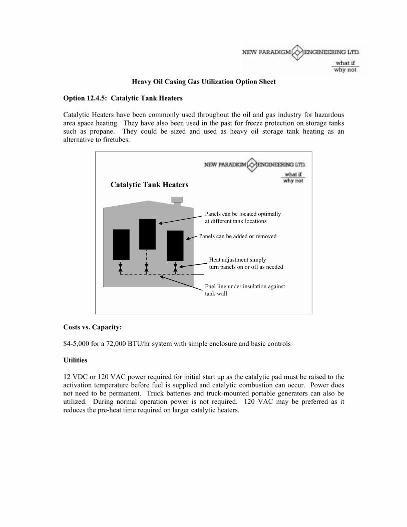
Heavy Oil Casing Gas Utilization Option Sheet
Option 12.4.5: Catalytic Tank Heaters
Catalytic Heaters have been commonly used throughout the oil and gas industry for hazardousarea space heating. They have also been used in the past for freeze protection on storage tankssuch as propane. They could be sized and used as heavy oil storage tank heating as analternative to firetubes.
Catalytic Tank Heaters
Panels can be added or removed
Panels can be located optimallyat different tank locations
Heat adjustment simply turn panels on or off as needed
Fuel line under insulation againsttank wall
Costs vs. Capacity:
$4-5,000 for a 72,000 BTU/hr system with simple enclosure and basic controls
Utilities
12 VDC or 120 VAC power required for initial start up as the catalytic pad must be raised to theactivation temperature before fuel is supplied and catalytic combustion can occur. Power doesnot need to be permanent. Truck batteries and truck-mounted portable generators can also beutilized. During normal operation power is not required. 120 VAC may be preferred as itreduces the pre-heat time required on larger catalytic heaters.

Installation:
Channels of insulation can be removed from the tank wall for retrofits. The heater panels andsimple enclosures could then be tack welded into position using brackets. As heatingrequirements change over the life of the well, panels can be easily added or removed as required.
The catalytic heaters require under _ psig so they can run on low pressure casing gas. It iscritical that the fuel line to the line heater be well insulated to avoid freezing off under winteroperations. Fuel lines can be run against the tank wall under insulation for freeze protection.
Operations and Maintenance
Operators are required for initial start up of the systems, which should take about _ hour. If theheaters have adequate fuel and air supplied they will then run unattended with no power. Theiroperation should be periodically checked during the operator’s daily run. For units with manualcontrol the operator will have to restart in the event they go out (e.g. loss of fuel supply toheater). Electronic control options are available that allow for automatic restart.
Benefits:
Catalytic heaters require less than _ psig and so are well suited to utilize low pressure casing gasas fuel. Catalytic heaters are flameless, and when used with proper controls are intrinsically safeso can be used in hazardous areas. If burners can be replaced with catalytic heaters, the normalspacing requirements could be reduced and potentially allow for smaller leases resulting inoperational and other cost savings. They are also quiet and odorless so are less obtrusive.
The heater panels are modular in nature and can easily be added or removed to another lease asheating requirements change. The heat input has a wide range of adjustment as individual panelscan be turned on or off with a valve.
Best Sites:
Low production leases with low pressure casing gas for burner replacement. For leases withinsufficient casing gas to meet full demand for fuel for burners, catalytic heaters can be used tomake use of all available vent gas, with purchased fuel being supplied to the burner as needed.
Examples of Vendors: Scott Can Industries Ltd. Edmonton Tel: 780-463-5505Fax: 780-463-2273 E-mail: [email protected]

Heavy Oil Casing Gas Utilization Option Sheet
Option 12.4.6: Fired Line Heater
Line heaters are commonly used in various applications in the conventional oil and gas industrysuch as hydrate prevention for gas, wax prevention in some oilfields, and oil/water separation asheater treaters at batteries. They could also be used as an alternative for production heating onheavy oil leases.
Fired Line Heater
Photos Courtesy Select Oilfield Leasing
Costs vs. Capacity:$9-15k for 250 MBTU/hr$15-20k for 500 MBTU/hr
Most line heaters are designed for high pressure and sour service. Potentially simpler and lessexpensive designs could be utilized for sweet heavy oil service.
Utilities:
Electrical power if electronic burner controls utilized.
Installation: If storage tanks are utilized then a small recirculating pump will be needed tomaintain temperature of production in the tank by cycling it back through the heater.
Pressure protection may be a concern. If storage tank is utilized, a stand pipe could be used as amechanism to ensure no over-pressure condition will occur. This will require adding a nozzle tothe tank above the normal tank level. The assumption is that the main flow into the tank will beat the bottom of the tank and will have a valve. The stand pipe entrance would have no valve butit can be disconnected and blanked off without completely emptying the tank if the line heater isremoved. If the lower valve were closed with the well producing, the production would justenter the tank through the upper nozzle with a slight increase in back pressure on the well butessentially the vessel would be an extension of the atmospheric tank.
The standpipe will also allow gas removal as it comes out of the production in the line. If the gasis left in the line it will take up line volume and reduce the energy efficiency of the heater.
Sand fall out in the flow line is another consideration. The heater inlet should be high, with theoutlet above the tank inlet with the line sloped down to allow sand to be carried away.
Operations and Maintenance:
Thermostat temperature control set point can be adjusted on flowing outlet temperature.
Energy Efficiency or Other Benefits: Line heaters would allow production to be heatedcontinuously while it is flowing to the tank instead of trying to heat it once it is in the tank andstagnant. This would significantly improve treating and breaking down foam. The line heaterwould ensure all production going into the tank gets heated. The fuel demand can be leveledbecause you can temperature control a flowing stream.
Line heaters could also be used to heat heavy oil production going into a flowline rather thangoing into a tank first and then having to pump it again.
The line heater could also be used to heat produced water for a mini waterflood as an additionalapplication. See Option Sheet 12.9.2. Hot Water Injection for further details.
Best Sites:Foamy wells, wells tied into a battery with flowlines rather than tanks and trucking. Pad siteswhere mini-waterflood could be utilized.
Examples of Where Tried: Echo heavy oil pipeline.
Examples of Suppliers:Select Oilfield Leasing, Edmonton, (780) 461-7677NWP Industries , Blackfalds, AB, (403) 885-4656Bilton Welding and Manufacturing, Innisfail, AB, (403) 227-7799Laren & D’Amico Mfg, Edmonton, (780) 434-9475

Heavy Oil Casing Gas Utilization Sheet
Option 12.4.7: Co-Generation
The flue or exhaust gas from pump drive engines and/or power generators represent a significantrecoverable waste heat source that could be used to heat production backing out purchased fuelfor burners.
Limitations: In most boiler applications the acid dewpoint of many flue gases is approximately230-250 deg F. As the temperature of the flue gases falls below this point, acidic vaporscondense. The resulting condensate is corrosive and will attack metal surfaces. In boilerapplications flue gas oxygen is kept at a minimum and the combustion/oxidation process isnearly stoichiometrically balanced.
For gas turbine combustion processes 6 to 7 times the air volume is put through the gas turbinethan would normally be required for complete combustion in a boiler. The result is that the gasturbine exhaust gas can have around 18% oxygen content and a much lower acid gasconcentration level, and a much lower acid gas saturation dewpoint. So corrosion problems maynot be as prevalent in oilfield applications.
In boiler applications when recovering heat from flue gas, the cooling of flue gas is usuallylimited to temperatures above 300-350 deg F. This leaves a comfortable margin of error abovethe flue gas acid dewpoint, but it also limits the amount of energy that can be captured from thesystem.
Flue gas can be cooled further to 130 deg F by using equipment with corrosive-resistant alloyswhich are more expensive or covered with suitable coatings such as Teflon. The resultingcorrosive condensate would have to be collected, treated, and disposed of accordingly.
So the flue gas either must be kept above the acid dewpoint, or the equipment must be designedto handle corrosive condensate. Again the acid dewpoint for gas turbine applications may bemuch lower than 250 deg F.
Line Heater The exhaust gas could be run through the heating coils of a line heater. This wouldensure that there is more heat transfer area and improve heating.
Intermediate Fluid Another option is to heat an intermediate heat transfer fluid with theexhaust gas such as glycol which could then be used for heat tracing of production lines. Thiscould be done using a simple heat exchanger designed for exhaust gas heat recovery. It couldalso be used to provide the energy to heat thermosyphon tubes (heat pipes). This technology isdescribed in Option sheet 12.4.3.
Firetube Finally the exhaust gas could be put through a storage tank firetube. Firetube energysavers that are available could help improve heating effectiveness (Auger shaped inserts thatcreate a spiral action of the flue gas, slowing it down and forcing it to the outwardly in contactwith the inner wall of the firetube).
See Options 12.8.2, 12.8.4, 12.8.6, & 12.8.8 for further information on and suppliers of co-genequipment.

Heavy Oil Casing Gas Utilization Option Sheet
Option 12.4.8: Use of Propane as Heater Make Up Fuel
Because casing gas is primarily methane it can be used interchangeably with purchased naturalgas as fuel without any major changes to most heating equipment. Propane has a significantlydifferent heating value and specific gravity than natural gas, and when used as a make up fuel itoften requires modifications to heating equipment such as pressure, orifice size, and air flow toachieve efficient and safe combustion.
Natural Gas vs Propane:
Fuel BTU/scf Specific Gravity Scf of Air Requiredto Burn 1 scf Fuel
Natural Gas 1000 .6 10Propane 2500 1.5 24
Either/Or Fuel Systems
Systems are quite common that automatically feed in purchased fuel as make up fuel for casinggas when the casing gas supply does not meet burner demand. For example the casing gas isregulated to run at 8-11 psig, and if the fuel line pressure drops below 6 psig a second regulatoropens feeding in purchased gas as required.
Dual Fuel Manifold – photo courtesy of Kenilworth Field Service
If a burner was specifically set up to run on natural gas and is switched over to 100% propane forextended periods of time, then the orifice, pressure, and air flow should be changed for propaneuse as the burner will be over fueled. The orifices and pressures for natural gas are larger thanthose for propane.
Some vendors have indicated that their burners can be set up to run on either natural gas,propane, or a mixture of the two. The burners are sized and airflow adjusted to accommodatethis fuel switching. Much of this ability is said to be attributed to the design of the burner itselfwith improved fuel/air mixing creating a very forgiving design.

Other vendors have indicated that the usual procedure if the burner may be using either naturalgas or propane as fuel is to size it somewhere between what it would be if sized specifically forone fuel or the other. This generally does lower efficiency but provides increased flexibility.
Another option is that if it a burner is going to be running primarily on propane, but may usecasing gas as available to back out purchased fuel, would be to size it for propane – worst casewould be that if casing gas is used as fuel the heater output would be decreased.
Propane Air Blending
Propane when mixed with air, will duplicate the burning characteristics of natural gas and allowsthe propane/air mixture to be used in existing natural gas burners, piping, and controls. Thistechnology is commonly used as a back up fuel source by industrial and utility users of naturalgas. A 60% propane, 40% air mixture is an equivalent fuel source to 1000 BTU/hr natural gas.
Packaged module units are available that incorporate a vaporizer, mixer, and surge tank. Theinlet is connected to the propane supply, and the outlet to the natural gas line. A 2.5 MMBTU/hrsystem costs around $20,0000. This is cost prohibitive for individual leases. However the basicconcept of mixing propane with air to create a fuel that can be used interchangeably with naturalgas is still valid, and there may be a simple and inexpensive way of accomplishing this on asmaller scale suitable for tank burners.
Dual Heater Options
It is also possible to install a dual burner system. The one burner would be set up for natural gasand normal use with temperature control set at 65-80 deg C. The other burner would be set upfor propane and be a back up in the event that the temperature in the tank dropped below 50 degC for example.
Examples of Suppliers:
Kenilworth Field Service, Islay, AB, (780) 744-3974 (burner fuel manifolds)
Gas Equipment Supplies, Edmonton (780) 468-4454 (propane/air mixing)
Canalta Controls, Red Deer, (403) 342-4494 (electronic burner control)

Heavy Oil Casing Gas Utilization Option Sheet
Option 12.5.1 Manipulate Conditions
A major concern with casing gas utilization is that liquids might accumulate and freeze off orthat equipment sensitive to liquids might be damaged. It is important in a system like this toinclude upstream liquid protection for sensitive equipment. There are three strategies: 1) Changethe conditions to prevent liquid water condensing and freezing, 2) prevent liquid freezing ( incombination with separators upstream of equipment) and finally, 3) use a process to removewater.
The last two strategies require equipment and are discussed in other option sheets. However,under some circumstance it may be possible to make adjustments to field conditions to preventwater from condensing and subsequently freezing and avoid needing drying equipment or freezeprotection.
Gas at equilibrium with liquid water is saturated at that pressure and temperature. This meansthat if the temperature is dropped or the pressure increase the water will condense. This is truefor casing gas off a reservoir, gas off of a compressor discharge bottle, or gas in a pipeline.
Manipulating conditions by increasing temperature (line heaters) and/or dropping pressure(valves) can be an effective method of avoiding liquids condensing and potentially freezing. Ifdistances in the network are small, in combination with protection for the casing gas consumerssuch as discussed in Option 12.3.4 and 12.3.5, these tactics may be enough. It is important thatthe under-saturated gas is not contacted with liquid water because it will re-establish a newequilibrium at the contact conditions.

Costs:
♦ Equipment Cost for Line Heaters if used
♦ Operating Costs for additional compression if required. Incremental fuel required for lineheaters if used, supplied by onsite use of vent-gas.
Utilities:
Increased operating cost for additional compression if required. Incremental fuel required for lineheaters (if used) supplied by onsite use of vent-gas.
Advantages or Benefits, Disadvantages:
Minimal equipment requirements. Requires some operator attention if conditions radicallychange at the site.
Best Sites:
♦ Sites that have pressure drop available ie. can operate compressors at higher dischargepressures or have reservoir conditions that allow wells to operate at higher pressures.
♦ Short pipeline networks.

Heavy Oil Casing Gas Utilization Option Sheet
Option 12.5.2: Winterization Heaters
Catalytic Heaters have been commonly used throughout the oil and gas industry for hazardousarea space heating. This system is based on heating the casing gas in a fuel line to keep water invapour form, minimizing condensation, and preventing freeze ups in the winter. The system isintended for leases where casing gas is already being successfully burned in tank burners in thesummer.
Costs vs. Capacity:
$3,800 (manual controls) - $4,600 (automatic controls) for a 6,000 BTU/hr heater which can heat500 scf/hr fuel for a tank burner
Utilities
12 VDC or 120 VAC power required for initial start up as the catalytic pad must be raised to theactivation temperature before fuel is supplied and catalytic combustion can occur. Power doesnot need to be permanent. On site power can be utilized from the battery on the engine with 12VDC off the starter battery, or 120 VAC obtained by installing a converter on the engine. Truckbatteries and truck-mounted portable generators can also be utilized. During normal operationpower is not required.

Installation:
The catalytic heaters are installed around existing fuel lines and enclosed in their own housing.They require a fuel tie in and electrical power tie in as described above. A decision should bemade as to the fuel source for the catalytic heaters – they can be run off purchased gas – eitherpropane or natural gas, or they can be run off casing gas. The pressure requirements and orificesizing for propane are different from natural gas/casing gas so they should not be switched backand forth. If using casing gas as fuel it should be insulated and pre-heated so that it does notfreeze off.
The systems should be started up in late fall before the ground starts to freeze, so that the entireunderground portions of the line can be warmed up and maintained above ambient conditions.
Operations and Maintenance:
Operators are required for initial start up of the systems, which should take about _ hour. If theheaters have adequate fuel and air supplied they will then run unattended with no power. Theiroperation should be periodically checked during the operator’s daily run. For units with manualcontrol the operator will have to restart in the event they go out (e.g. loss of fuel supply toheater). Electronic control options are available that allow for automatic restart.
Energy Efficiency or Other Benefits:
Catalytic heaters are flameless, and when used with proper controls are intrinsically safe so canbe used in hazardous areas. They are also quiet and odorless so are less obtrusive.
Best Sites:
Leases with burried fuel lines, purchased propane as make up fuel, and are successfully burningcasing gas in tank burners in the summer.
Examples of Where Tried: Husky Oil – Celtic and Tangleflags
Examples of Suppliers: Scott Can Industries Ltd. Edmonton Tel: 780-463-5505Fax: 780-463-2273 E-mail: [email protected]

Heavy Oil Casing Gas Utilization Option Sheet
Option 12.5.3: Electric Tracing
Electric heat tape is a heat tracing option (tracing with engine coolant is discussed in Optionsheet 12.5.4). The heat tape is applied to above ground fuel lines under insulation to minimizecooling of the casing gas and prevent the formation of free water that results in winter freeze ups.
The key consideration with electric heat tracing is power supply to the heat tape as 120 VACpower is generally required. On leases where electric power is available a transformer will likelybe required to tie in to the power supply. On leases with gas engines some form of powerconverter will be required to convert the engines 12 VDC power supply to 120 VAC, or a belt orhydraulically driven generator can be used.
Consideration should be given to the quality of the power supply. While it is possible to get lowcost converters most are intended for short term use, not “24 & 7” sustained industrial operation.Ideally the power supply should be voltage regulated, transformer controlled, or flow controlled(hydraulic driven) so that the power supply does not change when engine rpm is changed forproduction purposes. Options include belt driven generators and hydraulic driven generators.
All electrical wiring and connections should be appropriate for the electrical area classificationthey are being used in. Thermostats can be used for on-off control when the temperature of thepipe wall goes above or below a desired set point. Self-regulating heat tape is available thatadjusts its output based on demand. Finally, consideration should be given to prevent the enginebattery from being drained in the event that power is lost.
In hazardous classified areas, it is critical to ensure that the temperature for an electric heatingcable is less than the ignition temperature of the gases likely to be present. Therefore heat tracecable to be used in hazardous areas needs to be equipped with ground fault protection whichoperates in the event that the heat trace cable overheats and breaks down. The design of the cableshould also closely match the watts/meter required by the process line to ensure temperaturesstay within acceptable limits.
In some situations where limiting the current flow and therefore the heat to the pipelineinstallation does not effectively maintain the heat trace cable at acceptable operatingtemperatures, below maximum rated exposure limit, other options exist, such as mineralinsulated heater cable which can sustain higher exposure temperatures. Mineral insulated heattracing cable is more expensive, and needs to be precut by the manufacturer to the exact lengthbefore shipping, making the installation more costly. However, exposure temperatures of over800 F are possible with mineral insulated cable.
Costs:
Typical single well installation likely $1000-1500
Heat Tape - $3.50 - $5/foot120 VAC Converter (Gas Engine Sites) - $300-500

Heat Loss from Piping:
The chart provided gives the change in the heat capacity of methane for a given temperaturechange and flow rate of gas.
E.G. To increase the temperature of 900 m3/d of methane 20 deg C requires about 1000 BTU/hr(this does not account for heat transfer efficiency and heat losses)
Utilities:
120 VAC power required. At gas engine sites a power converter, belt or hydraulically drivengenerator can be used, while electric sites can be tied in with the use of a transformer.
Implementation/Regulatory Considerations:
Electrical area classification.
Best Sites: Above ground flow lines.
Examples of Where Tried: CNRL (Ranger) – Cold Lake
Examples of Suppliers:
Pyramid Corporation; Lloydminster (780) 875-6644; Elk Point (780) 724-3071
PowerComm Inc.; Lloydminster (780) 875-5241; www.powercomm.ab.ca;[email protected]
Thermon Heat Tracing Service Inc.; Calgary (403) 563-8461; www.thermon.com
Heat Input/Loss vs. Fuel Gas Flowrate
0
1000
2000
3000
4000
5000
Flowrate m3/d
10 Deg C20 Deg C30 Deg C40 Deg C50 Deg C

Heavy Oil Casing Gas Utilization Option Sheet
Option 12.5.4: Engine Coolant for Engine Fuel Heating and/or Tracing
As a rule of thumb, generally engines only convert about 1/3 of the total fuel energy theyconsume into mechanical horsepower – about another 1/3 is lost through the exhaust, and thefinal 1/3 is waste heat which will radiate from the engine itself and be dissipated by coolantthrough the radiator.
On leases with shacks and larger engines this radiant heat will keep the shack and any insidepiping in close proximity warmer than ambient conditions throughout the winter. Instead ofdissipating this waste heat through the radiator, the coolant can be used for heat tracing in _-3/8”copper or stainless steel tubing.
Some producers have indicated that engines typically consume about 100-150 scf/hr natural gas– this would represent about 30,000 – 50,000 BTU/hr waste heat that can be utilized. Furtherwork is required to determine how much of that heat can actually be transferred to fuel orproduction lines. We currently estimate 1/6 of the waste heat could be transferred throughtracing (5000-8000 BTU/hr for above example).
The heat tracing can be used to heat the fuel line to the engine, the fuel line to the burner if aboveground, and/or the production fuel line if above ground. Other equipment such as separators canbe traced to avoid freezing.
Return Line toWater Pump
Outlet off IntakeManifold
Coolant Hoses Run OutsideShack to Heat Trace Tubing

Costs vs. Capacity:
1/4”- 3/8” copper tubing and fittings about $200 (to trace 50-75’ and return)total cost installed and insulated about $400-$500
Installation:
The heat trace tubing is tied into the water pump for winter operations and can be disconnectedfor summer operations. The tubing should be clamped to the bottom of the desired line to assureclose contact, and the tracing and line are then co-insulated. On longer heat tracing lines thewater pump may not be able to handle the extra pressure losses and a make up pump may berequired (contact engine vendor for recommendations for specific case).
Operations and Maintenance:
Any tracing system will risk the potential for a coolant leak, which if undetected could result inengine overheating and shut down, and lost production. In addition any spills would have to becleaned up. Proper installation and occasional monitoring for any leaks should minimize theserisks. For these reasons heat tracing is best suited for above ground lines where it can bemonitored, and readily repaired if required.
Where Tried: Husky – Celtic and other areas – has been used successfully winter 2000/01 on afew wells, at time of writing hadn’t been through any really cold weather (below –20 deg C withwind-chill), CNRL (Ranger) – North Lindberg
Examples of Suppliers:Northern Industrial Insulation Contractors Inc. Bonnyville; Phone: (780) 826-6110;Fax: (780) 826-6236
Albrico Services Ltd. Bonnyville; Phone: (780) 826-7959; Fax: (780) 826-4737;[email protected]; www.albrico.com
Excel Insulations Lloydminster Phone: (780) 875-9398
Heat TraceTubing
ProductionFlow Line
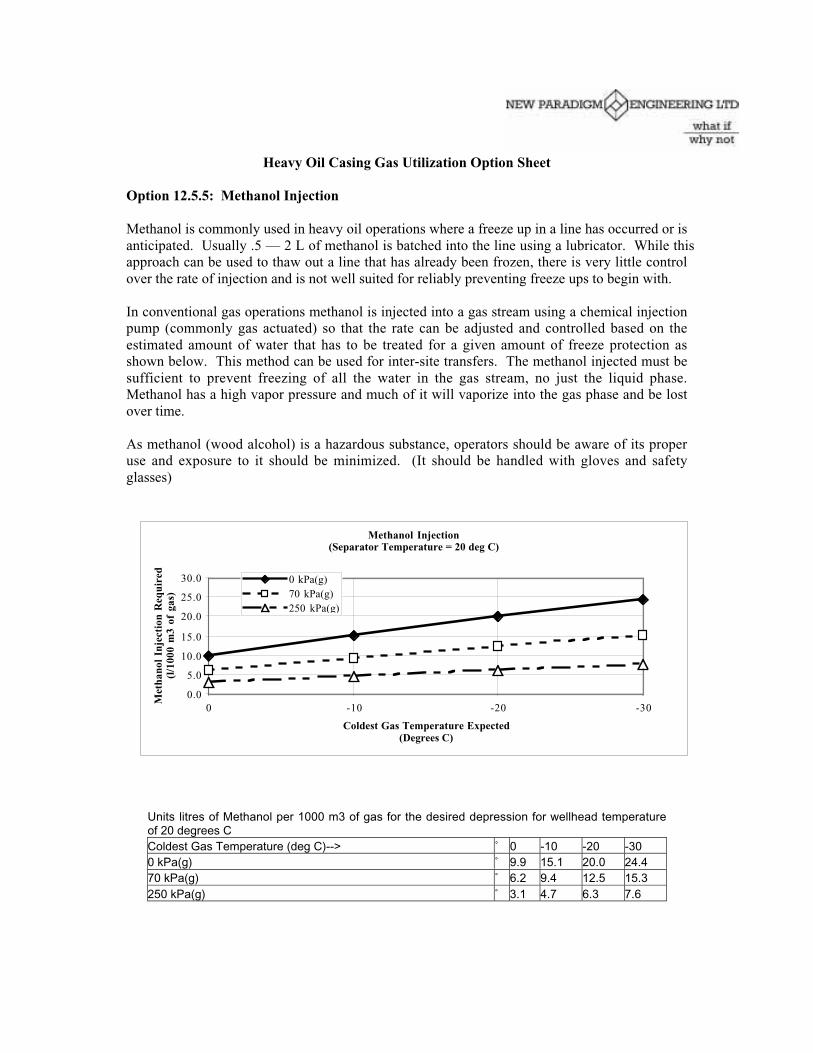
Heavy Oil Casing Gas Utilization Option Sheet
Option 12.5.5: Methanol Injection
Methanol is commonly used in heavy oil operations where a freeze up in a line has occurred or isanticipated. Usually .5 — 2 L of methanol is batched into the line using a lubricator. While thisapproach can be used to thaw out a line that has already been frozen, there is very little controlover the rate of injection and is not well suited for reliably preventing freeze ups to begin with.
In conventional gas operations methanol is injected into a gas stream using a chemical injectionpump (commonly gas actuated) so that the rate can be adjusted and controlled based on theestimated amount of water that has to be treated for a given amount of freeze protection asshown below. This method can be used for inter-site transfers. The methanol injected must besufficient to prevent freezing of all the water in the gas stream, no just the liquid phase.Methanol has a high vapor pressure and much of it will vaporize into the gas phase and be lostover time.
As methanol (wood alcohol) is a hazardous substance, operators should be aware of its properuse and exposure to it should be minimized. (It should be handled with gloves and safetyglasses)
Units litres of Methanol per 1000 m3 of gas for the desired depression for wellhead temperatureof 20 degrees CColdest Gas Temperature (deg C)--> ˚ 0 -10 -20 -300 kPa(g) ˚ 9.9 15.1 20.0 24.470 kPa(g) ˚ 6.2 9.4 12.5 15.3250 kPa(g) ˚ 3.1 4.7 6.3 7.6
Methanol Injection(Separator Temperature = 20 deg C)
0.0
5.0
10.0
15.0
20.0
25.0
30.0
0 -10 -20 -30
Coldest Gas Temperature Expected(Degrees C)
Met
hano
l In
ject
ion
Req
uire
d(l
/100
0 m
3 of
gas
)
0 kPa(g)70 kPa(g)250 kPa(g)

Example: To prevent freezing of 300 m3/d of casing gas at 70 kPa(g) down to – 20 deg C (tofuel engine and burner), would required 12.5 L of methanol per 1000 m3 of gas. So for 300m3/d the amount of methanol required is .3 x 12.5 = 4 L/d.
Costs:
$500-800 for gas actuated chemical injection pump
$.4-.5/L for methanol
Utilities:
Chemical injection pump can be gas actuated or electric (12VDC – can use pump drive enginebattery).
Examples of Where Tried:
Husky - Westhazel
Examples of Suppliers (Chemical Injection Pumps):
Arrow Specialty Co. Edmonton; Phone: (780) 437-4368; Fax: (780) 437-4368;www.arrowspecialty.com
BDM Supply Ltd. Edmonton; Phone: (780) 465-2200
Bruin Instruments Corp. Edmonton; Phone: (780) 430-1777
Norda-Tech Services Ltd. Edmonton; Phone: (780) 436-7755; Fax: (780) 436-7721
Panama Enterprises Inc. Edmotnon; Phone: (780) 452-5757

Heavy Oil Casing Gas Utilization Option Sheet
Option 12.5.6: Glycol Injection
The injection of glycol into a gas stream has the same effect that injecting methanol has:lowering the hydrate-formation point or in lower pressure gas streams, lowering the point atwhich the free water freezes.
Although it is more expensive than methanol, glycol has a relatively low vapour pressure and isalso relatively insoluble in hydrocarbon liquids and therefore, can be economically recovered.
The glycol is injected into the gas stream using a chemical injection pump (usually gas actuated)similar to the type of pump used for methanol injection. The rate of glycol injection can beadjusted and controlled based on the estimated water content of the stream versus the degree offreeze protection required.
Additional equipment is required to recover and reclaim the glycol. A three phase separatorseparates the water and glycol from the gas and hydrocarbon condensate. The water-glycolsolution is sent from the separator to the glycol reboiler. The gas off the separators is delivered tothe sales line and condensate is stored in a collection tank. The glycol is reconcentrated in theglycol reboiler and made available for re-injection into the gas stream.
Glycol Injection and Recovery System
GlycolTank
TC
Dry Gas
Condensateto tankage
Water Vapor Vent
Reboiler
3 Phase Separator
Injection Pump

Design Considerations:The point at which liquid water condenses from the effluent gas depends on the gas temperature,and the amount and concentration of the glycol injected.
90% Ethylene Glycol Injection (Separator Temperature = 20 deg C)
0.0
50.0
100.0
150.0
200.0
250.0
0 -10 -20 -30
Coldest Gas Temperature Expected (Degrees C)
0 kPa70 kPa250 kPa
Ethylene glycol is recommended for injection systems because it produces the greatest dew pointsuppression and has the lowest solubility in the highest molecular weight hydrocarbons.However, diethylene or triethylene glycol may be required if the vapourization losses from thereboiler are excessive.
Utilities:Power or gas required for chemical injection pump.Fuel gas required for glycol reboiler.
Advantages or Benefits, Disadvantages:Environmental impact of BTX emissions needs to be addressed.
Operation and Maintenance:Injection rates will require adjusting if gas conditions change substantially.
Best Sites:Most economic if vent gas can be tied into a gas gathering system with existing regenerationequipment with excess capacity available at a central gas treating facility.
Examples of Suppliers:Argo Sales Ltd.; Calgary Phone: (403)265-6633; Nisku Phone: (780) 955-8660Alco Gas and Oil Production Equipment , Calgary, Phone: (403) 243-5505

Heavy Oil Casing Gas Utilization Option Sheet
Option 12.5.7: Calcium Chloride Dryers
Casing gas is dried using consumable solid dessicant pellets such as Calcium Chloride (CaCl2) toremove water vapor. The pellets are contained inside one or more towers depending on thenumber of stages of drying required.
Photos courtesy Iron Horse Compression Ltd.
Costs vs. Capacity:
Capital Cost $2,500 – $20,000 depending on flow parameters (most single well leaseapplications likely <$5000).
Installation $200 - $1000.
Calcium Chloride Dessicant – about $2/lb; removes 3.5 lbs water/lb of dessicantLithium Chloride Dessicant – about $18/lb; removes 5.5 lb water/lb of dessicant (this wouldnormally be used as the final stage of drying for a multi-stage system)
Dessicant Cost can be under $.05 to $.75+/mcf depending on gas inlet conditions (temperatureand pressure) and level of drying desired. I.E. the amount of water that you are removing/mcfwill determine the operating cost.
Installation:
The gas should ideally be processed through the dryer at the highest practical pressure (25 psigrecommended for best economics) and lowest possible inlet temperature for the lowest operatingcost (as the gas will contain the least amount of water vapour). Dessicant is not designed toremove free water. While free water may not exist when gas first comes off the wellhead,cooling can cause free water to form (e.g. gas line going from inside shack to outside in winter).
Dryer

A small seperator and/or piping should be arranged such that free water is removed before casinggas enters the dessicant tower. If the gas is compressed upstream of the dryer, the heat ofcompression should be removed (e.g. an ambient air heat exchanger), and free water removed.
Freeze protection may be required in the winter for the tower itself as the brine can form a verythick sludge – locating tower inside shack, or insulating/heating the bottom of towers that arelocated outside.
Accurate specification of gas conditions to vendors (T and P of inlet gas, desired lb/mmcf ofwater vapor in outlet gas) is critical to proper sizing and economics.
Operations and Maintenance:
The CaCl2 is a consumable desiccant that forms a brine solution at the bottom of the tower as itdries the gas. The brine should be drained and collected daily. The solid pellets need to bereplaced periodically, as often as a weekly basis. The collected brine must be properly disposedof.
Environmental Impacts: Brine Disposal.
Best Sites:
Drying casing gas will be the preferred option when the gas is being transported a long distance(e.g. through an existing line gas system) or for commercial sale. It is also the best option if linesare not insulated and are exposed to ambient conditions.
Examples of Where Tried:
Wascana - Luseland; CNRL (Ranger) – North Lindbergh; Husky – Marwayne, Westhazel
Examples of Suppliers:
Argo Sales Ltd., Nisku; Phone: (780) 955-8660; Fax: (780) 955-9422;E-mail: [email protected]
Ironhorse Compression Ltd., Edmonton; Phone: (780) 462-6840; Fax: (780) 450-0124;[email protected]; www.jacgas-ihc.com

Heavy Oil Casing Gas Utilization Option Sheet
Option Sheet 12.5.8: Pressure Swing Adsorption (PSA) Dryers
Pressure-swing adsorption is a widely applied technology for separating components of a gasstream inexpensively. It can be applied in casing gas water removal and will also remove anyheavy hydrocarbons present in the gas at the same time.
Separation is achieved through selective concentration of the water vapor from the feed gas on asolid adsorbent, followed by a desorption step of the recovered water vapour. PSA systemscycles through the pressurization-adsorption and depressurization-desorption providing waterremoval on a continuous basis.
Pressure Swing Adsorption (PSA) Dryers
120 mscfd shown - Photo courtesy Eagle Pump & Compressor Ltd.
Costs:
9 k$ (35 mscfd); 18 k$ (105 mscfd); 35 – 44 k$ (700 mscfd)
Issues:
This type of drier should be designed for an inlet temperature no higher than 100°F, losingefficiency at higher temperatures.
This type of dryer operates best at pressures exceeding 150 psig. It is possible to dry at lowerpressures than optimum but the amount of purge gas increases. As well, equipment size increasesaffecting capital cost. At an operating pressure of 150 psig the purge volume is about 10% of thefeed stream. At 65 psig the purge increases to about 18 – 20 %. It may be possible to recycle thevent stream back to the inlet of the compressor.

Utilities:
Electricity for solenoid switching: 110 V, 12 V from a hydraulic power pak, 24 V from a PLC, orsolar powered with battery also available.
Advantages:
Unmanned operation; Low exit dewpoint obtained, capable of meeting high-pressure sales gasdewpoint spec, 4 lbs./mmscf.
Disadvantages:
Desiccant sensitive to poisoning by lube oils; Rated capacity declines with pressure
Installation:
Skid Mounted
Examples where applied:
Pan Canadian Petroleum, WabascaBurlington Energy
Examples of Suppliers:
Eagle Pump and Compressor Ltd., Calgary Phone: 1-888-831-2777

Heavy Oil Casing Gas Utilization Option Sheet
Option Sheet 12.5.9: Glycol Dehydrators
A TEG or DEG dehydration system is an absorption process and incorporates a glycol contactor,regeneration system and associated equipment: lean/rich glycol heat exchanger, glycol pump ,surge tank and glycol filter. It is capable of providing reliable dewpoint suppression to high-pressure sales requirements, less than 4 lbs./mmscf. Because of the large initial investment, andhigher operating and maintenance requirements it is more applicable to much larger gas volumeslocated at a centralized facility.
Surge Drum
Flash T
ankLean Glycol
Dry Gas
WetGas
FreeLiquid
Rich Glycol
GlycolContactor
InletScrubber
Reboiler
StillFlash Gas
Water Vapor
Filter
Glycol Dehydration
Adapted from GPSA Fig. 20-53
Costs:
50+ k$ (105 mscfd)
Custody Transfer:
It is capable of providing reliable dewpoint suppression to high-pressure sales requirements, lessthan 4 lbs./mmscf.
Utilities:
Natural gas for regenerator burner and pump (or electric).

Advantages:
Excellent dewpoint suppression to sales gas spec of 4 lbs./mmscf
Disadvantages:
Regenerator vent gas' BTX emissions an environmental issue.
Operation and Maintenance:
Requires monitored operations.
Best Sites:
Manned centralized site.
Examples where applied:
Common gas plant equipmentBig Bend Gas PlantRedwater Gas Conservation Plant
Examples of Suppliers:
Argo Sales Ltd.; Calgary Phone: (403) 265-6633; Nisku Phone: (780) 955-8660Alco Gas and Oil Production Equipment , Calgary, Phone: (403) 243-5505

Heavy Oil Casing Gas Utilization Option Sheet
Option Sheet 12.6.1: Steel Pipelines
The use of yellow jacketed steel for gas gathering systems in Alberta is conventional technology.
Design Considerations:Standard sizing formula and pressure-temperature rating information can be found in suchreferences as the GPSA Engineering Data Book.
Costs:
Nominal PipeSize
Sch 40 PipeCost $/km
Y.JacketCost $/km
InstallationCost $/km
Total Cost$/km
InstallationMethod
2” 6,180 1,850 19,000 27,030 Open cut3” 8,320 2,490 20,000 30,810 Open cut4” 10,295 3,075 22,000 35,370 Open cut6” 15,410 4,600 29,500 49,510 Open cut
Installation:
Must be installed with yellow jacket for corrosion protection. This limits its installation methodto conventional open cut trenching methods.
Advantages:
In the gas gathering design temperature range, steel has the advantage relative to polyethylene ofbeing temperature insensitive. Polyethylene at temperatures above 23°C is pressure derated andrequires a higher wall thickness (lower SDR). This happens for steel as well but at temperaturesthat are well about those experienced in gas gathering systems.
Steel is easily traceable.
Disadvantages:
Steel must be encased in yellow jacket (polythylene) for corrosion protection. This can limit itsinstallation to conventional open cut trenching methods and creates a breach in the coating wherejoining takes place.
Larger number of joining procedures during installation.
Examples of Suppliers:
CE Franklin Ltd10050 29A AveEdmonton, Ab944-1000

Heavy Oil Casing Gas Utilization Option Sheet
Option Sheet 12.6.2: Plastic Pipelines
High Density polyethylene pipelines are becoming more popular in gas gathering becauserelative to conventional steel gathering systems the material is cost competitive , easy to installand has greater electrolytic corrosion resistance. It is generally supplied in continuous length“reels” up to 1200 m.
Gas Flow Calculation:
Polyethylene compared to other conventional materials offers superior flow characteristics fornatural gas. This is primarily due to the low coefficient of friction on the interior surface of thepipe. The following is a Mueller flow calculation for pressures exceeding 1 psig:
727.2
575.022
21
425.0
2826DX
L
PP
GQh
−=
Where:Qh = Gas Flow rate (Standard cubic feet per hour)G = Specific gravity of gas (natural gas = 0.65 , air = 1.0)P1 = Pipe inlet pressure (psia)P2 = Pipe outlet pressure (psia)L = Length of pipe (feet)D = Inside diameter of pipe in inches
Sample Calculations:
Q ( mscfd) D (inches) P1( psia) P2( psia) L (feet)279.2 2.096 (2” SDR 17) 64.7 62.7 1000197.7 1.847 (2” SDR9) 64.7 62.7 1000176.5 2.096 (2” SDR 17) 29.7 27.7 1000125.03 1.847 (2” SDR9) 29.7 27.7 1000
Working pressure: Note that the relationships between pipe size, wall thickness, and continuous operating pressureis summarised on the table at the end of this option. Please note the continuous operatingpressure is temperature dependent and if the temperature exceeds the 23 C stated on the table thecontinuous operating pressure must be de-rated.
Costs:
Although it has also has application for larger line sizes, use of polyethylene in smaller diameterlines 6” and under for low pressure gas gathering applications is particularly attractive because oflow material costs and because these small sizes can be plowed in from reels. Costs are alsosummarized on the table at the end of this section.
Installation:Plowing (planting) up to 8 feet is possible up to 6” at temperatures as low as -20°C fromreels up to 1200 m. Lengths are butt fused. A tracer wire is required to make it possible tolocate pipe.

Advantages:Polyethylene is not susceptible to electrolytic corrosion. Higher flow rates versus steel. Plowingin and long reel lengths reduce installation costs.
Disadvantages: A tracing wire is required to enable PE pipe to be located. Potentially pressure de-rating occursat gas gathering operating temperatures above 23°C resulting in increased wall thicknesses.
Best Sites: For dry gas best applied in pressures below 400 psig and temperatures below 60 °C. Dry gasgathering involves a service fluid that, under the design and operating conditions of the pipeline,contains no associated hydrocarbon liquids and is above the hydrocarbon dew point. The servicefluid, in this case, may contain measurable quantities of water.
Examples where applied:RenaissancePanCanadian
Examples of Suppliers:Polytubes Inc.Edmonton, AB(780) 453-2211
Enerline Restoration Ltd.Calgary, AB
1(888)377-6677
Rangeland Oilfield Inc.Calgary, AB
1(403) 261-1071
PE-3408 High Molecular Weight High Density Polyethylene (HDPE) Pipe
For Gas Gathering, Multiphase, Low Vapour Pressure Liquid And Oilfield Water Services “Working Pressure” based on 50-year life at a 2:1 safety factor. *The requirements for polyethylene dry gas distribution pipelines as stated in Clause 13 of CSA
Z662-99.
Nominal Diameter
Average Outside
Diameter
Standard Dimension
Ratio
Nominal Wall
Thickness
Nominal Internal Diameter
AveragePipe
Weight
WorkingPressure(psi) at23°C
*DRY GAS
MaterialCost
$/km
Install’nCost
$/km
TotalCost
$/km
(Inches) (in) (SDR) (in) (in) (lb./ft)
2 2.375 17 0.140 2.096 0.429 100 1,480 7,000 8,500 2.375 9 0.264 1.847 0.762 200 2,630 7,000 9,650 2.375 5 0.475 1.425 1.226 400 4,220 7,000 11,240
3 3.500 17 0.206 3.008 0.932 100 3,210 8,000 11,230 3.500 9 0.389 2.722 1.656 200 5,700 8,000 13,720 3.500 5 0.700 2.100 2.662 400 9,170 8,000 17,190
4 4.500 17 0.265 3.971 1.540 100 5,300 9,500 14,820 4.500 9 0.500 3.500 2.737 200 9,430 9,500 18,950 4.500 5 0.900 2.700 4.400 400 15,160 9,500 24,680
6 6.625 17 0.390 5.846 3.338 100 11,500 15,500 27,020 6.625 9 0.736 5.153 5.932 200 20,430 15,500 35,950 6.625 5 1.325 3.975 9.537 400 32,850 15,500 48,370

Heavy Oil Casing Gas Utilization Option Sheet
Option 12.6.3: Modular Compressed Natural Gas Transport
In cases were individual wells are isolated and cannot economically be tied into a natural gaspipeline to either export or import natural gas for use as fuel. It may be economic to utilizeMobile Gas Storage to move surplus vent gas between sites to allow vent gas to displace propaneuse. To our knowledge this has not been utilized for the oil and gas industry, but there aresystems of aluminum/composite construction that are available for use in the automotive industryto allow substitution of natural gas as an alternate to gasoline or propane. This option also mightprovide the opportunity to convert producer vehicle fleets to compressed natural gas as an outletfor surplus vent gas, and to displace use of gasoline in operating areas.
System requires small volume but high discharge pressure (3000+ psi) compressors to charge thestorage modules from a site with surplus vent gas or from a centralized location on a lowpressure vent gas gathering network.
Utilities:
Assume compression can use electric power (purchased or generated at a site) or gas drivenengines.
Installation:
At sites using compressed gas trailers would be parked at the site until they are nearing depletionand then switched out for refilling.

Gas Collection and Sales
Low Pressure< 50 psig
Freeze protect
To/from County
To/from HP Supply/Sales
Local Sales System 150-200 psig
No liquid water
High Pressure>1000 psig>4# Water
Net Demand Sites
Truck

Heavy Oil Casing Gas Utilization Option Sheet
Option Sheet 12.7.1: Rotary Vane Compressors
This type of compressor technology has been traditionally used in vapor recovery systems andvacuum generation applications where relatively low discharge pressure is required. Morerecently in the oil industry they have been applied in reducing well backpressure.
Rotary Vane Compressor
600 MSCFD Shown - Photo Courtesy Eagle Pump & Compressor Ltd.
Costs: 25 – 35 k$ installed with electric driver. (3.5 – 35 mscfd)
Design Considerations: A single compression stage is only capable of 25- 30 psig differential.If a higher operating pressure is required for the gathering system a second compression stage isrequired. This may make a single stage reciprocating compressor more economical.
Utilities: Available with electric, hydraulic or natural gas engine drive.
Advantages or Benefits, Disadvantages: Rotary Vanes are more tolerant of inlet liquids. Thismay be a consideration for wells operating at close to 0 psig.
Examples where applied: PanCanadian Petroleum, Wabasca
Examples of Suppliers:
Eagle Pump and Compressor Ltd, Calgary; Phone: 1-888-831-2777
Daval Industries, Nisku; Phone: (780) 955-7547

Heavy Oil Casing Gas Utilization Option Sheet
Option Sheet 12.7.2: Beam Mounted Gas Compressors
These are reciprocating type compressors mounted on a stand and driven by the walking beam ofa conventional pumpjack unit. These have been used in use to draw casing gas off of oil wells toreduce backpressure on the formation face and increase well productivity or as boostercompressors.
Beam Mounted Compressor
Photo courtesy Iron Horse Compression Ltd.
JACGAS Compressor Capacities (mscfd)
Stokes/min 6” x 48”Dbl Acting 8” x 48”Dbl Acting 10” x 48”Dbl ActingSuction Pressure Suction Pressure Suction Pressure14 psia 24 psia 14 psia 24 psia 14 psia 24 psia
5 9.0 15.45 16.7 28.65 26.6 45.66 10.8 18.54 20.04 34.38 31.92 54.727 12.6 21.63 23.38 40.11 37.24 63.848 14.4 24.72 26.72 45.84 42.56 72.96
Control is accomplished by discharge recycle. Strategies for optimizing control if the recylcebecomes excessive as flows change over time are reducing the stokes/min if possible, changecompressor to single acting, and reducing the stroke length.
Costs:
11.5 – 16.5 k$ installed. A suction scrubber is recommended for an additional cost of about 2.5k$. Rent to purchase options are available.
Utilities:
None required unless spare pumpjack utilized.
Installation:
Any liquids should be knocked out upstream of the compressor using a small scrubber. Thecompressor should be set up to handle a relatively constant feed stream by providing a dischargeto suction recycle.
Best Sites:
Where existing or spare pumpjack is available.
Examples of Suppliers:
Ironhorse Compression Ltd., Edmonton; Phone: (780) 462-6840

Heavy Oil Casing Gas Utilization Option Sheet
Option Sheet 12.7.3: Liquid Eductors
If oil production is pipelined to a central facility, there is more flexibility to treat and re-distribute the gas for internal consumption or for sales.
Liquid eductors are venturi jet devices that use pressurized liquid to entrain, mix and pumpgases. Eductors consist of two basic parts, the motive nozzle, which converts the pressure energyto kinetic (velocity) energy and the suction chamber/diffuser section where the entrainment andmixing take place.
Eductors
Discharge
Suction
Motive
Using eductors applies in those cases where oil is shipped out by pipeline to a central treatingfacility. Depending on the pressure of the motive (oil) stream and the differential between it andthe educted stream (casing gas), this application may be as simple as a draft tube eductor or mayrequire taking a slip stream off of the oil pipeline and using a small booster pump to create thepressure drop in the eductor sufficient to entrain the casing gas.
Costs:
3500 US$ (4” eductor based on 35 mscfd vent gas, 100 psig motive fluid) + booster pump cost.
1500 US$ (1-1/2” eductor bases on 3.5 mscfd vent gas, 100 psig motive fluid) + booster pumpcost.

Design Considerations:
Motive Inlet Pressure to exceed 30 psig.Viscosity of motive fluid cannot exceed 900 SSU. (approx. 190 cp)
Advantages or Benefits, Disadvantages:
Eductors are standard equipment in vacuum generation technology. They are inexpensive,rugged, have no moving parts, and require almost no maintenance or operator attention.
Best Sites:
Using eductors applies in those cases where oil is shipped out by pipeline to a central treatingfacility.
Examples of Suppliers:
Schutte & Koerting, Pennsylvania (215) 639-0900 www.s-k.com
Fox Valve Development Corp., New Jersey (973) 328-1011 www.foxvalve.com

Heavy Oil Casing Gas Utilization Option Sheet
Option Sheet 12.7.4: Screw Compressors
Oil injected rotary screw compressors are positive displacement devices that consist of tworotors intermeshing to compress the gas. The gas entering at the suction flange is conveyed to thedischarge port by continuously diminishing spaces between the convolutions of the two rotors.The result is gas compressed to the final pressure before it is discharged. The oil acts as alubricant separating the two screws and provides cooling.
Generally screw compressors are applicable to larger volumes ( > 200 mscfd) but it can beapplied to lower flow by slowing the unit down and recycling discharge gas to the suction of thecompressor at the expense of efficiency.
Hydraulic, electric, and natural gas engines are available as drive systems for these types ofcompressors. Natural gas engines are significantly more costly.
Screw Compressor
52 BHP Shown - Photo courtesy Eagle Pump & Compressor Ltd.
Costs:
55-60 k$ (105 mscfd) installed; 95-150 k$ (700 mscfd) installed
Design Considerations:
Screw compressors are applicable to larger gas flows, best applied above 200 mscfd.Need to control both inlet and outlet pressure for stable operation. Alternative is to providevariable speed drive.

Utilities:
Hydraulic, electric, and natural gas engines are available as drive systems for these types ofcompressors. Natural gas engines are significantly more costly.
Advantages or Benefits, Disadvantages:
Screw compressors are attractive because they are very low maintenance and simple in designrelative to other types of compressors.
Operation and Maintenance:
Seal oil must be replaced periodically and is expensive.
Examples where applied:
Anadarco, hydraulic driven screw compressor
Examples of Suppliers:
Daval Industries, Nisku; Phone: (780) 955-7547
Eagle Pump and Compressor Ltd, Calgary; Phone: 1-888-831-2777

Heavy Oil Casing Gas Utilization Option Sheet
Option 12.7.5: Reciprocating Compressors
Mini-compressors can be utilized in situations where there is insufficient casing gas supplypressures to fuel the tank burners. Reciprocating compressors have been the most commonapplication. For on site energy use the gas volumes and pressure differentials required are verylow, and the incremental load on the pump driver is often within an acceptable range.
Costs vs. Capacity:
$3,000 - $12,000 installed (20-50 mcf/d)
Example:
To compress casing gas from 0 psig to 15 psig requires a compression ratio of about 2 (singlestage), and about 40 BHP/mmcf/d. To compress 20 mcf/d would require about 1 BHP.
The discharge temperature for the above example would be about 65 deg C assuming an inlettemperature of 20 deg C.
Utilities:
Commonly belt driven off the engine as shown above, there are also options that can be drivenelectrically (12VDC, 24VDC, 120VAC) and hydraulically.

Installation:
Any liquids should be knocked out upstream of the compressor using a small scrubber. Anotherkey consideration is surge protection as casing gas flows and burner fuel requirements are highlyvariable, while the compressor itself should be set up to handle a relatively constant feed stream.Allowances should be made for excess gas to be vented upstream and downstream of thecompressor. Volume bottles or surge drums may be required.
Other Benefits:
Compressing the gas will increase its temperature. As stated earlier for an inlet temperature of20 deg C and a compression ratio of two, the outlet temperature would be about 65 deg C.Heating a gas increases the amount of water vapor it can hold, so the heat of compression may besufficient to prevent condensation on lease and allow the use of casing gas throughout the winterwhen used in conjunction with insulation and dewatering as described in option sheets 12.3.4.and 12.3.5.
Examples of Where Tried:
CNRL (Ranger) – North Lindbergh (pad wells)
Examples of Suppliers:
Daval Industries, Nisku; Phone: (780) 955-7547; Fax: (780) 955-2673;[email protected]; www.davalindustries.com
Secure Oil Tools, Calgary; Phone: (403) 264-6663; Fax: (403) 264-0511;[email protected]; www.secureoiltools.com
Eagle Pump & Compressor Ltd., Calgary, Phone: 888-831-2777; Fax: (403) 253-8884;[email protected]; www.eagle-pc.com

Heavy Oil Casing Gas Utilization Option Sheet
Option Sheet 12.7.6: Reciprocating Compressors – Low Pressure 1 Stage
Mini-compressors can be utilized on individual wells to boost casing gas pressures into a smalllocal casing gas gathering system to supply internal fuel needs, transferring casing gas from highgas producers/low fuel consumers to low gas producers/high fuel consumers. The gas volumesand pressure differential may still be low enough that the incremental load on the pump driver isstill within an acceptable range. If not the compressor packages can be supplied with electric ornatural gas engines.
Reciprocating Compressor
Photo courtesy Eagle Pump & Compressor Ltd.
Costs:
16-24 k$ installed with electric driver.
Example:
To compress casing gas from 0 psig to 50 psig requires a compression ratio of about 4(attainable in a single stage) and about 97 BHP/mmscfd. To compress 35 mscfd will requireapproximately 3.5 BHP. A higher operating pressure for the gathering system will require asecond compression stage.
Utilities:
Can be belt driven off the engine if capacity is available. If not the compressor packages can besupplied with electric, hydraulic drives or natural gas engines.

Installation:
Any liquids should be knocked out upstream of the compressor using a small scrubber. Anotherkey consideration is how to handle the variability of the casing gas flows.The compressor itselfshould be set up to handle a relatively constant feed stream by providing a discharge to suctionrecycle. Allowance for excess gas venting upstream and downstream of the compressor shouldbe provided and volume bottles may be required.
Examples where applied:
Mercury Electric; fuel gas for microturbines
Examples of Suppliers:
Daval Industries, Nisku; Phone: (780) 955-7547
Ironhorse Compression Ltd., Edmonton; Phone: (780)462-6840
Eagle Pump and Compressor Ltd, Calgary; Phone: 1-888-831-2777

Heavy Oil Casing Gas Utilization Option Sheet
Option Sheet 12.7.7: Reciprocating Compressors – Low Pressure 2 Stage
Mini-compressors can be utilized on individual wells to boost casing gas pressures into a lowpressure sales gas system (150 – 200 psig.)
Reciprocating Compressors -Low Pressure 2 Stage
45 HP, 2 stage Corken D791L – Photo Courtesy Daval Industries
Costs:
60-95 k$ installed with electric driver ( 105 mscfd).
Example:
To compress casing gas from 0 psig to 200 psig requires a compression ratio of about 4 (requires2 stages) and about 182 BHP/mmscf. To compress 105 mscfd will require approximately 19BHP.
Utilities:
Compressor packages can be supplied with electric, hydraulic drives or natural gas engines.Natural gas engines are approximately 10 k$ more expensive.
Installation:
Any liquids should be knocked out upstream of the compressor using a small scrubber. Anotherkey consideration is how to handle the variability of the casing gas flows. The compressor itselfshould be set up to handle a relatively constant feed stream by providing a discharge to suctionrecycle. Allowance for excess gas venting upstream and downstream of the compressor shouldbe provided and volume bottles may be required.
Examples where applied:
PanCanadianAnadarco
Examples of Suppliers:
Daval Industries, Nisku; Phone: (780) 955-7547
Ironhorse Compression Ltd., Edmonton; Phone: (780)462-6840
Eagle Pump and Compressor Ltd, Calgary; Phone: 1-888-831-2777

Heavy Oil Casing Gas Utilization Option Sheet
Option Sheet 12.7.8: Reciprocating Compressors – Single Stage Booster
Small single stage reciprocating compressors be also be utilized for compressing gas from a localgas gathering system into low pressure sales system.
Reciprocating Compressors –Single Stage Booster
95 HP Corken – Photo Courtesy Daval Industries
Costs:
95-125 k$ installed (700 mscfd) with electric driver.
Example:
To compress casing gas from 50 psig to 200 psig requires a compression ratio of about 3.3(single stage) and about 73 BHP/mmscf. To compress 105-700 mscfd will require approximately7.7-51 BHP.
Utilities:
Compressor packages can be supplied with electric or natural gas engines. Natural gas enginesare approximately 30 k$ more expensive.

Installation:
Any liquids should be knocked out upstream of the compressor using a small scrubber. Thecompressor itself should be set up to handle a relatively constant feed stream by providing adischarge to suction recycle. Allowance for excess gas venting upstream and downstream of thecompressor should be provided and volume bottles may be required.
Examples where applied:
PanCanadian
Examples of Suppliers:
Daval Industries, Nisku; Phone: (780) 955-7547
Eagle Pump and Compressor Ltd, Calgary; Phone: 1-888-831-2777
Ironhorse Compression Ltd., Edmonton, Phone: (780) 462 - 6840

Heavy Oil Casing Gas Utilization Option Sheet
Option Sheet 12.7.9 Reciprocating Compressors – High Pressure Sales
Reciprocating compressors are commonly used to boost gas pressures from gas gatheringsystems into a high pressure sales gas systems.
This would not be economic except for large capacity gas volumes, e.g. done in conjunction withgas wells and existing sales and gathering systems.
Example:
To compress casing gas from 50 psig to 1000 psig requires a compression ratio of about 4 (twostages required) and about 190 BHP/mmscf. To compress 105-2100 mscfd will requireapproximately 20-399 BHP.
Utilities:
Compressor packages can be supplied with electric or natural gas engines. Natural gas enginesare approximately 25% more expensive.
Installation:
Any liquids should be knocked out upstream of the compressor using a small scrubber. Thecompressor should be set up to handle a relatively constant feed stream by providing a dischargeto suction recycle.

Heavy Oil Casing Gas Utilization Option Sheet
Option 12.8.1: Thermoelectric Generation
550 W TEG by Global Thermoelectric
Cost vs. Capacity
Sizes range from 15 W to 550 W for individual Thermoelectric Generator (TEG) units. Gasconsumption varies respectively from 1.5 m3/d to 48 m3/d for individual units, assuming a gasheating value of 1000 BTU/SCF or 37.7 MJ/Sm3. Prices range from $2570 for a 15 Watt unit to$22 000 for a 550 Watt unit, excluding installation. On a cost per kW basis these units arerelatively expensive as compared to other technologies, but are useful for generating reliablepower in small quantities for remote applications.
Energy Efficiency
They are known for safe and reliable operation, but are very low in efficiency, and can be below5% electrical conversion efficiency.
Environmental Impact
These units will reduce greenhouse gas emissions. Every tonne of Methane that is burnedinstead of vented reduces greenhouse gas emissions by 18 tonnes CO2 equivalent.

Utilities
None required. Only natural gas or a source of heat.
Application
Thermoelectric generators are used for a variety of remote power applications in the oil and gasindustry and the pipeline industry. Uses include cathodic protection, remote SCADA operations,etc.
Installation
The units can handle up to 200 ppm of H2S. Liquid slugs can cause flame out and thereforeliquids should be removed from the gas supply.
Operations and Maintenance
The TEG generators have no moving parts, and therefore are relatively maintenance free, andcan operate for extended periods unattended. The units produce power by the direct conversionof heat into electricity.
Other Benefits
Reliable, relatively noise free operation.
Best Sites
Remote applications where small quantities of gas can be utilized to generate power rather thanpurchasing power.
Examples where tried
TransCanada Pipelines for remote pipeline valve operations.
Examples of Suppliers
Global Thermoelectric: Telephone: (403) 236-5556
Potential to Out Source
Installation, repairs are readily handled by companies such as:
Prologic Controls: Telephone: (403) 250-3266
or Syndicated Technologies: Telephone: (403) 543-4060

Heavy Oil Casing Gas Utilization Option Sheet
Option 12.8.2: Thermoelectric Cogeneration
Heat Recovery Unit shown is by Global Termoelectric
Cost vs. Capacity
The TEG (Thermoelectric Generator) does give off significantly more heat energy than itconverts to electricity as it converts less than 5% of the energy to electricity. The potentialtherefore exists to capture some of this excess heat for building heating or other purposes.
A combined TEG and heat recovery system module to produce 3000BTU/hr of building heat and60 Watts of electricity can be purchased for $9600, excluding installation costs. The costcomprises the cost of the heat recovery system which is approximately $5000 and the balance isthe cost of the TEG itself.
A combined TEG and heat recovery system module to produce 12000BTU/hr of building heatand 120 Watts of electricity costs $12300, excluding installation costs.
As the units are completely modular, the cost of installation would be the cost of attaching theunit to the exterior of the building requiring heating and the cost of the gas hookup.
On a cost per kW basis these units are relatively expensive as compared to other technologies,but are useful for generating reliable power and heat in small quantities for remote applications.

Energy Efficiency
They are known for safe and reliable operation, but are very low in efficiency, and can be below5% electrical conversion efficiency. However, a significant amount of heat is generated whichcan be utilized and which will greatly increase the energy efficiency utilization.
Environmental Impact
These units will reduce greenhouse gas emissions. Every tonne of Methane that is burnedinstead of vented reduces greenhouse gas emissions by 18 tonnes CO2 equivalent.
Utilities
None required. Only natural gas.
Application
Thermoelectric generators with heat recovery units can be used for keeping remote RTUbuildings powered and heated.
Installation
Should be installed outdoors to that combustion gases are not a hazard.
Operations and Maintenance
The TEG generators have no moving parts, and therefore are relatively maintenance free and canoperate for extended periods unattended. The units produce power by the direct conversion ofheat into electricity and the excess heat can be used for building heating.
Other Benefits Reliable, relatively noise free operation.
Best Sites
Remote applications where small quantities of gas can be utilized to generate power rather thanpurchasing power.
Examples where tried Remote oilfield SCADA operations.
Examples of Suppliers Global Thermoelectric: Telephone: (403) 236-5556
Potential to Out Source
Installation, repairs are readily handled by companies such as:
Prologic Controls: Telephone: (403) 250-3266
or Syndicated Technologies: Telephone: (403) 543-4060

Heavy Oil Casing Gas Utilization Option Sheet
Option 12.8.3: Microturbines
Cost vs. CapacityThe sizes of the more commonly available microturbines range as follows: 30kW, 45 kW, 60kW, 75kW. Gas consumptions of these range from 10 MCF/D to 20 MCF/D at rated outputpower and assuming a gas heating value of 1000BTU/SCF or 37.7 MJ/Sm3.
Capital costs for these units range from $1000/kW to $1500/kW before installation. Additionalcosts to install the unit may include, if required, a power line for exporting the power to the gridat $22000/km construction cost, gas line connection, liquids knock out vessel, and compression,if the gas pressure is insufficient. The cost of compression can range from $5000 to $10 000.Step up transformers, if required, utility disconnects, bi-directional metering for power exports,and other related equipment can further increase the installation cost, where required anddepending on the site specifics.
Energy Efficiency Efficiencies for energy conversion to electrical energy range are in the 25% to 30% range.(Through cogeneration options, this overall energy utilization can be increased by two to threefold.)
Environmental ImpactCombustion efficiency ranges in excess of 99.5%, and so virtually complete incineration of thehydrocarbon input stream is achieved, to produce essentially only water vapour and carbondioxide. Low emissions and Nitrogen oxide (NOx) levels of less than 25 ppm are readilyachievable. Some of the manufacturers have achieved NOx levels of less than 10 ppm and TotalHydrocarbons (THC) of less than 10 ppm, which are among the lowest levels of any fossil fuelcombustion technology.

Utilities Black Start Options are available where utility power is unavailable. Cost of theblack start option is approximately $ 5000 including batteries.
Application Microturbines are gaining acceptance as a means of eliminating emissions thatwould otherwise be vented or flared. A significant number of microturbines have been operatingfor a year or more in oil field power applications, including prime power generation to supplypower for a 400 kVA ESP (electric submersible pump) in an oil field application. Additionally,units have been installed to mitigate landfill gas emissions, and for reliable standby power.
Installation Attention is to be paid to having a liquids knockout vessel or separator ahead ofthe unit, as well as attention to the gas velocities in the fuel gas line coming from the well headto prevent liquid slugs from accumulating and entering the turbine.
Depending on the choice of manufacturer, input gas pressures range from 5 psig to 75 psig. Forless than 5 psig pressure, fuel gas pressure booster options are available.
Operations and Maintenance Microturbine maintenance costs constitute no more thanreplacement of consumables such as filters, and scheduled overhauls. A major maintenanceoverhaul is scheduled after 10 000 hours of operation.
Other Benefits Green house gas emissions reductions, emission trading credits, increasedpower reliability, reduced power costs.
Best Sites Where gas supply can be assured for a number of years or where units can readilybe moved from well to well as gas declines. Where gas can be gathered relatively easily from anumber of wells to increase supply. Relatively close to existing power lines, if power exports aredesired.
Examples where triedSuncor Energy, Red Deer fieldTrail Road Landfill, OttawaPan Canadian, oilfield flare gas applicationsSecure Power, oilfield application, Carrot Creek
Examples of Suppliers/ManufacturersHoneywell Power Systems Inc.Capstone Turbine CorporationElliott Energy Systems
Potential to Out Source
A number of independent power generators have emerged as a result of deregulation of theelectric utility industry and are involved in providing services in the microturbine area:
Mercury Electric Corporation, Tel: 403-261-8611Mariah Energy Corp., Tel: 403-264-2880Secure Power Systems., Tel: 403-232-6599

Heavy Oil Casing Gas Utilization Option Sheet
Option 12.8.4: Microturbine Cogeneration
Schematic of Microturbine Cogeneration installation by Capstone
Cost vs. Capacity
Cogeneration, or CHP (Combined Heat and Power), is defined as the generation of electricenergy and commercial or industrial quality heat or steam from a single facility.
The incremental installed cost of a cogenerator over straight generation is usually the cost of theheat recovery system which can be a Heat Recovery Steam Generator (HRSG), an Air-to-Liquidheat exchanger or an Air-to-Air Heat Exchanger, depending on the host facility process heatingrequirements. Hot glycol can be used for building heating or hot exhaust gas can be used forprocess treating of product.
A number of manufacturers have recently made available heat recovery units to be used with thevarious microturbines. Some manufacturers have developed heat recovery units, which can beintegrated into the microturbine footprint while others have developed stand alone units, whichcan be coupled with external ducting to the exhaust systems of a number of differentmicroturbines. Cost of the latter heat recovery unit suitable for capturing the exhaust heat from a75kW microturbine is of the order of $15000, excluding installation costs. Installation costswould vary dependent on the application. If an Air-to-Air heat exchanger is utilized, it will be thecost of the ducting to the host facility requiring the heating. If an Air-to-Liquid heat exchanger iscalled for, it will be the cost of the liquid or glycol lines and the flow control valves and controlsto modulate the quantity of heat being sent to the host facility.
Energy Efficiency
For a microturbine, the electrical efficiency is around 25-30 percent. The overall cogeneratorenergy efficiency can be over 75 percent at normal operating conditions, dependant on hostfacility process heating requirements.

Environmental Impact When comparing a gas-fired cogenerator to a stand-alone coalfired power generation facility, we can expect approximately a 60 percent reduction in carbondioxide emissions, a 95 percent reduction in nitrogen oxide emissions and 100 percent reductionin particulate emissions for the same amount of electrical power generated.
Utilities Black Start Options are available where utility power is unavailable. Cost of theblack start option is approximately $ 5000 including batteries.
Application Microturbines in conjunction with heat recovery units are gaining acceptance as ameans of gaining energy efficiencies and reducing operating costs. Applications have includedproviding building heating and process heating.
Installation Attention is to be paid to ensuring that the heat recovery unit does not result inexcessive back pressure on the turbine exhaust as this will reduce turbine output power. This canbe addressed by ensuring close proximity between the microturbine and heat recovery unit. Also,the ducting should not apply excessive pressure onto the recuperator in the microturbine.
Operations and Maintenance Heat recovery unit maintenance costs are not expected tobe significant, as there are no moving parts, other than flow controls.
Other Benefits Green house gas emissions reductions, emission trading credits, reducedpower and heating costs.
Best Sites Where there is a significant heat load, preferably a year round, high load factorheat load.
Examples where tried
Osaka Gas, Japan, has combined a unit with a fired heat exchanger to produce steamHoneywell 75 kW CHP at Health Canada Midland Road, Scarborough, ONSponsors Enbridge, Kinetrics (Ontario Power Generation, Hydro One), Public Works Canada,and CETC
Examples of Potential Suppliers
Unifin International, London, Ontario Tel: 800-349-7820Mariah Energy Corp., Tel: 403-264-2880, has developed an integrated heat recovery system withthe 30 kW Capstone unit
Potential to Out Source
A number of independent power generators have emerged as a result of deregulation of theelectric utility industry and are involved in providing services in the microturbine area:
Mercury Electric Corporation, Tel: 403-261-8611Mariah Energy Corp., Tel: 403-264-2880Secure Power Systems., Tel: 403-232-6599
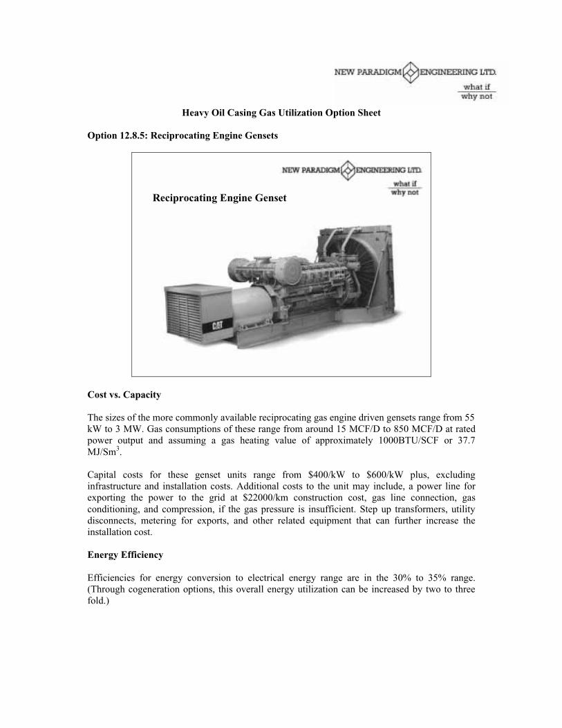
Heavy Oil Casing Gas Utilization Option Sheet
Option 12.8.5: Reciprocating Engine Gensets
Reciprocating Engine Genset
Cost vs. Capacity
The sizes of the more commonly available reciprocating gas engine driven gensets range from 55kW to 3 MW. Gas consumptions of these range from around 15 MCF/D to 850 MCF/D at ratedpower output and assuming a gas heating value of approximately 1000BTU/SCF or 37.7MJ/Sm3.
Capital costs for these genset units range from $400/kW to $600/kW plus, excludinginfrastructure and installation costs. Additional costs to the unit may include, a power line forexporting the power to the grid at $22000/km construction cost, gas line connection, gasconditioning, and compression, if the gas pressure is insufficient. Step up transformers, utilitydisconnects, metering for exports, and other related equipment that can further increase theinstallation cost.
Energy Efficiency
Efficiencies for energy conversion to electrical energy range are in the 30% to 35% range.(Through cogeneration options, this overall energy utilization can be increased by two to threefold.)

Environmental Impact Nitrogen oxide (NOx) emission levels for the natural gas engines arearound 19 g/bhp-h. By comparison some of the leading gas turbines will only produce 0.166g/bhp-h of NOx, i.e. a 100 fold reduction in NOx emissions over the reciprocating engine. Evenwith the addition of low NOx catalyst systems to the reciprocating engine genset, the gas turbinewill produce considerably less NOx emissions. Carbon monoxide (CO) emissions are alsoconsiderably higher for the reciprocating genset as compared to the turbine. Total Hydrocarbons(THC) are also 5 to 10 times higher for the reciprocating engine than for the turbine.
Utilities Black Start Options are available where utility power is unavailable.
Application Reciprocating engine gensets have gained wide acceptance as a means of providingreliable standby power. Very often they are used in Gas Turbine Power Generation applicationsto provide standby or black start capability.
Installation Attention is to be paid to having a liquids knockout vessel or separator ahead of theunit, as well as attention to the gas velocities in the fuel gas line to prevent liquid slugs enteringthe unit.
Operations and Maintenance Maintenance costs are generally higher for the reciprocating gasengine driven genset and can be three times that of a turbine. A rough estimate is around1.5c/kWhr.
Other Benefits Standby power capability. Quick start up capability.
Best Sites
Where gas supply can be assured for a number of years. Where gas can be gathered relativelyeasily from a number of wells to increase supply. Relatively close to existing power lines, ifpower exports are desired.
Examples where tried
Widely used in standby power applications, and oilfield applications.
Examples of Suppliers/Manufacturers
CaterpillarCumminsIngersoll-Rand Canada Inc.
Potential to Out Source
A number of independent power generators are active in the business as a result of deregulationof the electric utility industry and are involved in providing services:
Canadian Hydro Developers Inc. Tel: 403-269-9379Encore Energy Solutions L.P, Tel: 403-297-0342Mercury Electric Corporation Tel: 403-261-8611

Heavy Oil Casing Gas Utilization Option Sheet
Option 12.8.6: Reciprocating Engine Cogeneration
Reciprocating Engine Cogeneration
Cost vs. Capacity - Cogeneration, or CHP (Combined Heat and Power), is defined as thegeneration of electric energy and commercial or industrial quality heat or steam from a singlefacility.
The incremental installed cost of a cogenerator over straight generation is usually the cost of theheat recovery system. In the case of a reciprocating gas engine genset, the reciprocating gasengine is generally equipped with a jacket water cooling system and a radiator and fan. This canreadily be can be used for building heating.
Installation costs would vary dependent on the application. In situations where the existingreciprocating engine radiator can be utilized as a Liquid-to-Air heat exchanger, it will be the costof the ducting, which may be required to duct the heat to the host facility requiring the heating,or the duct required to exhaust excess heat from the building. If a Liquid-to-Liquid heatexchanger is called for, it will be the cost of the Liquid-to-Liquid heat exchanger, the liquid orglycol lines and the flow control valves and controls to modulate the quantity of heat being sentto the process or host facility.
Energy Efficiency - Efficiencies for energy conversion to electrical energy are in the 30% to35% range for reciprocating engine gensets. A further 20 to 40% of the energy is rejected to thejacket water, 30 to 40% to the engine exhaust, and 5% to the environment. Through variouscogeneration options, the overall energy utilization can be increased by two to three fold. Theoverall cogenerator energy efficiency can therefore be over 80%, dependant on host facilityprocess heating requirements. Heat rejected by the jacket water can be totally recovered, and 50to 70% of the exhaust energy can potentially be recovered.

Environmental Impact - Nitrogen oxide (NOx) emission levels for the natural gas engines arearound 19 g/bhp-h. (By comparison some of the leading gas turbines will only produce 0.166g/bhp-h of NOx, i.e. a 100 fold reduction in NOx emissions over the reciprocating engine. Evenwith the addition of low NOx catalyst systems to the reciprocating engine genset, the gas turbinewill produce considerably less NOx emissions.) Total Hydrocarbons (THC) are also 5 to 10times higher for the reciprocating engine than for the gas turbine.
Utilities - Black Start options are available where utility power is unavailable.
Application - Reciprocating engine gensets equipped with heat recovery are a means of gainingenergy efficiencies and reducing operating costs. Applications have included providing buildingheating and process heating. Utilizing the heat transferred from the engine radiator provides airat 38 to 65 Degrees C (100 to 150 Degrees F). This recovered heat is suitable for preheatingboiler combustion air, space heating, etc. The system cost is minimal and energy efficiencies ofapproximately 60% can be attained. Alternatively, a shell and tube heat exchanger can be used totransfer rejected engine heat to a secondary circuit, often a process stream. Usually a loadbalancing heat exchanger is used in parallel with the process heat exchanger to absorb excessheat when the process load is insufficient to absorb the gas engine rejected heat.
Installation - Manufacturers generally do not recommend a heat recovery system in which theprocess water circulates in the engine. Experience has shown that in the majority of cases, it isnot economical to treat the quantity of process water to the level required to avoid enginemaintenance problems. The system must also provide adequate coolant flow through the engineso that the engine coolant differential temperature does not exceed the manufacturerspecifications, generally around 8.5 Degrees C.
Operations and Maintenance - Heat recovery unit maintenance costs are not expected to besignificant, as these are mainly flow controls. Maintenance costs, though, are generally higherfor the reciprocating gas engine driven genset and can be three times that of a gas turbine. Arough estimate is around 1.5c/kWhr.
Other Benefits - Can be used to reduce existing boiler or treater heating costs. Existing boilercan be used for peaking or standby heating requirements.
Best Sites - Where gas supply can be assured for some time. Where gas can be gatheredrelatively easily from a number of wells to increase supply. Relatively close to existing powerlines, if power exports are desired.
Examples where tried - Used in prime power applications where utility power is not readilyavailable and building heating is required, including oilfield applications.
Examples of Potential Suppliers - Caterpillar, Cummins, Ingersoll-Rand Canada Inc., UnifinInternational, London, Ontario Tel: 800-349-7820
Potential to Out Source
Canadian Hydro Developers Inc. Tel: 403-269-9379Encore Energy Solutions L.P, Tel: 403-297-0342

Heavy Oil Casing Gas Utilization Option Sheet
Option 12.8.7: Gas Turbine Gensets
Gas Turbine Gensets
Cost vs. Capacity
Sizes can range from around half a megawatt to upwards of thirty megawatts.
Installed capital costs can be as low as $1000/MW, or lower. Operating costs and maintenancecosts, on a unitized basis, can also be lower than the microturbines, because of some economiesof scale.
Additional costs to install the unit may include, if required, a power line for exporting the powerto the grid at $22000/km construction cost, gas line connection, liquids knock out vessel, andcompression, if the gas pressure is insufficient. Step up transformers, if required, utilitydisconnects, bi-directional metering for power exports, and other related equipment can furtherincrease the installation cost, where required and depending on the site specifics.
Approximately 400 MCFD (approximately 11000 m3/d) of gas with a heating value of 1000BTU/ft3 will produce approximately 1.2 MW of electric power for export onto the grid or forlocal consumption.
Energy Efficiency
For a gas turbine, efficiencies for energy conversion to electrical energy are in the 25% to 30%range. Through cogeneration options, this overall energy utilization efficiency can be increasedby two to three fold.

Environmental Impact - Combustion efficiency ranges in excess of 99.5%, and so virtuallycomplete incineration of the hydrocarbon input stream is achieved, to produce essentially onlywater vapour and carbon dioxide. Low emissions and Nitrogen oxide (NOx) levels of less than25 ppm are readily achievable. Some of the manufacturers have achieved NOx levels of less than3 ppm.
Utilities - Black Start Options are available where utility power is unavailable.
Application - Primary power in remote locations. Standby power. Option for solving larger flareproblems.
Installation - Attention is to be paid to having a liquids knockout vessel or separator ahead ofthe unit, as well as attention to the gas velocities in the fuel gas line coming from the well headto prevent liquid slugs from accumulating and entering the turbine.
Operations and Maintenance - For the gas turbine genset, maintenance costs are lower thanthat for comparably sized reciprocating gas engine gensets, and can be as low as one third that ofa reciprocating gas engine driven genset. Whereas a reciprocating gas engine driven genset maycost 1.5c/kWh in maintenance costs, the gas turbine can be as low as 0.5c/kWh maintenancecosts.
Other Benefits - Green house gas emissions reductions, emission trading credits, increasedpower reliability, reduced power costs.
Best Sites - Where gas can be gathered relatively easily from a number of wells to increasesupply. Relatively close to existing power lines, if power exports are desired.
Examples where tried - Westcoast Energy, Ft Nelson, BC
Examples of Suppliers/Manufacturers
Solar TurbinesGeneral ElectricWestinghouse
Potential to Out Source
A number of independent power generators are active in the business as a result of deregulationof the electric utility industry and are involved in providing services;
Canadian Hydro Developers Inc. Tel: 403-269-9379EMF Corporation, Tel: 403-547-8259 / 403-208-2000Encore Energy Solutions L.P Tel: 403-297-0342
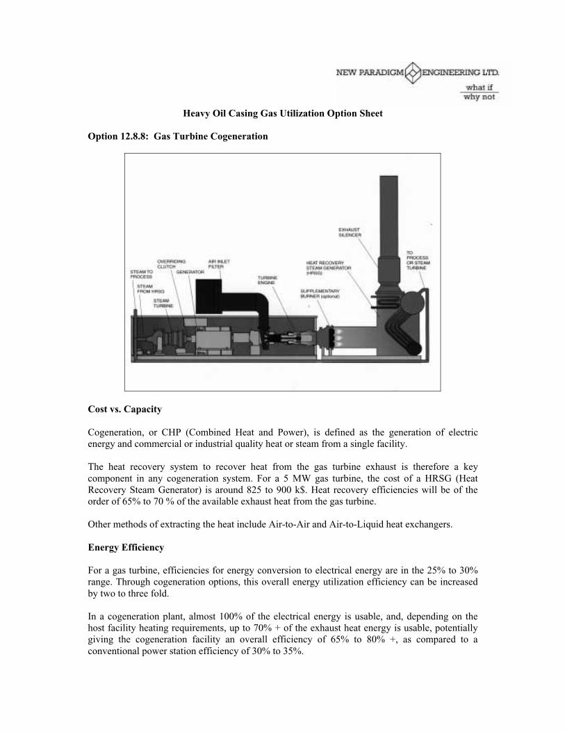
Heavy Oil Casing Gas Utilization Option Sheet
Option 12.8.8: Gas Turbine Cogeneration
Cost vs. Capacity
Cogeneration, or CHP (Combined Heat and Power), is defined as the generation of electricenergy and commercial or industrial quality heat or steam from a single facility.
The heat recovery system to recover heat from the gas turbine exhaust is therefore a keycomponent in any cogeneration system. For a 5 MW gas turbine, the cost of a HRSG (HeatRecovery Steam Generator) is around 825 to 900 k$. Heat recovery efficiencies will be of theorder of 65% to 70 % of the available exhaust heat from the gas turbine.
Other methods of extracting the heat include Air-to-Air and Air-to-Liquid heat exchangers.
Energy Efficiency
For a gas turbine, efficiencies for energy conversion to electrical energy are in the 25% to 30%range. Through cogeneration options, this overall energy utilization efficiency can be increasedby two to three fold.
In a cogeneration plant, almost 100% of the electrical energy is usable, and, depending on thehost facility heating requirements, up to 70% + of the exhaust heat energy is usable, potentiallygiving the cogeneration facility an overall efficiency of 65% to 80% +, as compared to aconventional power station efficiency of 30% to 35%.

Environmental Impact - When comparing a gas-fired cogenerator to a stand-alone coal firedpower generation facility, we can expect approximately a 60 percent reduction in carbon dioxideemissions, over a 95 percent reduction in nitrogen oxide emissions and a 100 percent reductionin particulate emissions for the same amount of electrical power generated.
Utilities - Black Start Options are available where utility power is unavailable.
Application - Cogeneration or (CHP) is becoming increasingly accepted as a means ofsignificantly improving energy efficiency and reducing emissions in many applications whereboth heat and power are required. Applications include process heating and steam stimulation ofproduction wells.
Installation - Attention is to be paid to ensuring that the heat recovery unit does not result inexcessive back pressure on the turbine exhaust, as this will reduce turbine output power. This canbe addressed by ensuring close proximity between the turbine and heat recovery unit.
Operations and Maintenance - Heat recovery unit maintenance costs are not expected to besignificant, as there are no moving parts, other than flow controls.
Other Benefits - Green house gas emissions reductions, emission trading credits, increasedpower reliability, reduced power costs.
Best Sites - Where there is a significant heat load, preferably a year round, high load factor heatload. Where gas supply can be assured for a number of years. Where gas can be gatheredrelatively easily from a number of wells to increase supply. Relatively close to existing powerlines, if power exports are desired.
Examples where triedWestcoast Energy & CU Power International – McMahon Plant, Taylor BC, 120 MW & 500 000lbs/hr of steam.Westcoast Energy & Centra Gas, Ontario – Boise Cascade Pulp & Paper, Ft Frances, 100 MW,600 000 lbs/hr steam
Examples of Suppliers/Manufacturers
Babcock & Wilcox20 S. Van Buren Avenue
Barberton, Ohio 44203-035United States of America
Innovative SteamTechnologies200 Avenue
Galt, Ontario N1R 8H5
International Unifin, Inc1030 Clarke Side Road
Boxes 5395 Stn. BLondon, Ontario
Potential to Out Source - A number of independent power generators are active in the businessas a result of deregulation of the electric utility industry and are involved in providing services;
Canadian Hydro Developers Inc. Tel: 403-269-9379EMF Corporation, Tel: 403-547-8259 / 403-208-2000Encore Energy Solutions L.P Tel: 403-297-0342

Heavy Oil Casing Gas Utilization Option Sheet
Option 12.8.9: Fuel Cells and Combinations
The ONSI Commercial phosphoric acid fuel cell (PAFC), with 1900 SCF/h NG, produces200 kW and 750,000 Btu/hr heat, <2500F
Cost vs. Capacity
There are over 20 companies currently developing fuel cells. Sizes are expected to range fromseveral kW to over several MW.
The first commercial fuel cell was developed by ONSI Corporation and produces around 200kW.At a cost of approximately $6000/kW, fuel cell options are still prohibitively expensive.
Step up transformers, if required, utility disconnects, and metering for power exports and otherrelated equipment can further increase the installation cost.
Energy Efficiency
Efficiencies for energy conversion to electrical energy are in the 50% plus range. (Through gasturbine-fuel cell combinations, the overall energy utilization efficiency can potentially beincreased to over 70%.)
Environmental Impact
The output from the hydrogen fuel cell process includes electricity, water and heat. It operatesvirtually pollution-free, eliminating air emissions normally associated with acid rain, smog andglobal warming. The fuel cell combines hydrogen and oxygen to produce electricity and water.The hydrogen can be obtained by reforming natural gas.

Utilities
Black Start Options are available where utility power is unavailable.
Application
For reliable standby power or for prime power in certain applications.
Installation
Requires a source of hydrogen fuel, which can be obtained by reforming natural gas.
Operations and Maintenance
Maintenance costs are predicted to be low, based on the fact that the fuel cell operates somewhatlike a battery, which has no moving parts.
Other Benefits
Green house gas emissions reductions, emission trading credits, increased power reliability.
Best Sites
Where it is very critical to maintain power during utility outages.
Examples where tried
Approximately 100 ONSI fuel cells are in operation around the world. Examples include militaryapplications and the U.S. Postal Service. A fuel cell system is being installed by ChugachElectric Association Inc. at the Anchorage, Alaska, Mail Processing and Distribution Facility.
Examples of Suppliers/Manufacturers
ONSI Corporation, South Windsor, Connecticut.Ballard Power Systems'
Potential to Out Source
A number of independent power generators have emerged as a result of deregulation of theelectric utility industry and are involved in providing services, though none are at time of writingoffering fuel cell technology as the technology is still under considerable development and isexpensive.

Heavy Oil Casing Gas Utilization Option Sheet
Option 12.9.1: Methane Reinjection
Some producers are proposing or even initiating methane reinjection schemes for pressuremaintenance. A surplus or watered out well could be utilized as an injector and compressors (seegas collection and compression options) could be used to generate high-pressure (1200-1500 psigassumed) gas for injection. Injection volumes could be adjusted to match the amount of casinggas available or could potentially be supplemented with gas from other sources if a constantinjection rate was preferred.
Enhanced Oil Recovery – Methane Reinjection
Watered out Well
T= 150-200 CP= 9000 -16000 kPaMethane
1000 m3/d gas à 900 m3/d gas injection Assume 10% of gas needed for fuel
Injection Compressors(Vent Gas for Fuel)
Vent Gas
Gas Dryers
Benefits:
• Conventional technology, using off the shelf equipment.• Casing gas can supply the engine fuel as well as the injectant supply.• Gas is conserved and may be produced later on at a higher rate than would be more economic
to recover on an on-going basis.
Operations and Maintenance:
• Operation of gas driven compressors, depending on the type and size of unit, is likely to besomething that the existing operators in an area have experience with.
• Costs of purchase and installation of compressor equipment is well established• Support and maintainance of equipment should be easy to find• There are many suppliers and options for compression equipment.

• Units can be leased, rented or purchased and moved easily between sites as gas volumeschanged.
• Would help to avoid the need for large gas pipeline systems.
Limitations:
• Gas injection for heavy oil is not usually as effective for high viscosity oil as it is for light oil.• Most heavy oil wells are completed near the top of the producing zone to avoid water
breakthrough, this will make them more susceptible to gas breakthrough between wells,especially if there was a pre-existing gas zone at the top of the formation.
• Gas breakthrough would make gas production and venting volumes much more difficult topredict from surrounding producers.

Heavy Oil Casing Gas Utilization Option Sheet
Option 12.9.2: Hot Water Injection
In cases where a site has a surplus of produced water and vent gas, as well as a watered outproducing well, or a section of horizontal well that might be isolated for water injection, it maybe advantageous to reinject the hot produced water. The produced water has already been heatedto allow for oil/water separation and can be heated further utilizing a line heater and surpluscasing gas. As the two feed streams (water and gas) are already on the lease there is little on-going operating cost to run such a system. A surface PCP type or other positivedisplacement/metering type pump, powered from the artificial lift system or a separate gasengine, could be used to pump the water to a higher pressure, so the water can be heated to ahigher temperature without forming steam. The assumption is that this low cost energy added tothe producing formation would result in some incremental oil production and enhanced recoveryform the formation through other wells in the area.
Enhanced Oil Recovery – Hot Water
T=65-80C
Lease ProducedWater Storage
Surface PCP
Watered out Well
Line HeaterT= 150-200CP= 400-1400 kPa
1 mmbtu/hr = 1000 m3/d gas @ 70% effCan heat 100 m3/d of water by 100 deg CHow many m3 oil would this add to production?
Casing Vent Gas Avoids ProducedWater Trucking to Disposal $3+/m3
In the case of a pad lease where one well has watered out and can be used as an injector, the tankfor that well can become a water storage tank and receive water transferred from the otherproducing tanks or potentially even trucked from other nearby leases. The water would bepumped out of the tank by a horizontal surface PCP through a line heater and the water sent toinjection. The line heater would operate off surplus casing gas from the producing wells.Metering of the water transfers would be required but can be done with standard positivedisplacement meters. Operators could transfer water before loading oil to trucks so that pumpswould not be necessary to transfer water between tanks.

Benefits:
Generally any energy that can be added to a producing formation will result in increasedproduction from the formation. Normally any EOR method would have energy and injectantsupply costs associated with it. Payouts on the capital invested may be very rapid. This methodwould contribute to increased production in a number of ways:• Add heat to the reservoir. With heavy oil, viscosity is usually a log function with respect to
temperature so even a small increase in temperature in the formation will significantly reduceoil viscosity and surface tension to increase relative permeability.
• Water Displacement will move the heated oil to producing wells from the injector.• Water will replace voidage and help maintain reservoir pressure.• Water reinjected will not have to be trucked and disposed of elsewhere so unit operating
costs will be reduced.• Use of casing gas will generate GHG emissions credits while at the same time generating
incremental oil revenue.• Gas used for increased oil recovery is usually royalty free.• An additional benefit can be realized from watered out wells and abandonment can be
postponed.• While the injected water would be hot it can be limited to temperatures allowable by the
original well completion materials.
Costs:
Incremental capital would have to be invested to convert a well to receive disposal water, converta production tank to water service; install piping and equipment (traced and insulated for freezeprotection) to allow metered or measured water transfer from production tanks to the water tank,installation of a new pump with connection to a drive energy source and a line heater to heat thepressurized water before injection.
All the equipment used can be portable and relocated to other leases as production of gas, oil orwater declines at any given lease.
Operations and Maintenance:
Most of the incremental operating effort will be involved in transferring of water to the waterdisposal tank and ensuring that the water is relatively clean. As long as injection rates into anyindividual well are kept relatively low and the water hot, the injection pressures required, and theamount of water clean-up required should be low as the fluid head of the water in the tubing willprovide much of the energy. Other costs would be just maintenance costs for the incrementalwater injection pump and line heater.
Limitations:Testing would be required to determine how much the produced water can be heated.

Heavy Oil Casing Gas Utilization Option Sheet
Option 12.9.3: Conventional Steam Injection
Generally steam injection is preferred if there is a shortage of a low cost source of water for hotwater flooding. Steam will transfer more energy to the reservoir for a given mass of water,however, steam generation requires a much higher degree of water treatment, higher pressuresand higher temperatures and therefore requires more equipment at a higher cost. Also as thesteam temperatures are higher a greater amount of the energy is lost to the wellbore in theinjector well. Fresh water would have to be brought to the site as it would not likely be costeffective to attempt to use produced water. Conventional tube boilers require that the water besoftened to prevent scale build-up on the tubes. For fresh water this can be accomplished with aportable ion exchange water softening plant that is regenerated with salt. Packaged watertreatment and boiler units are available or can be fabricated in a range of sizes and skid mountedto allow them to be transported between sites. Another downside to steam injection is that theinjector well casing would have to be designed to withstand the high steam temperatures andpressures, and there may be potential for loss of producer wells if steam breaks through and theyare not designed for thermal operation.
Enhanced Oil Recovery – Steam Generation
T=20C
Treated FreshWater Storage
ReciprocatingBFW Pump
Watered out Well
Steam GeneratorT= 300-350CP= 9000 -16000 kPa
1 mmbtu/hr = 1000 m3/d gas @ 70% effTurns 15 m3/d of water into 80% quality steamHow many m3 oil would this add to production?
Casing Vent GasFresh Water Trucking& Softening $4+/m3
Benefits:
• The volume of steam injected can be matched to some extent with the amount of surplus ventgas available in an area to maximize use of the casing gas.
• Heat energy will likely have a greater impact on production than pressure maintenance.

Operations and Maintenance:
Steam generation facilities will require greater operating attention and 24 hour monitoring, eitheron-site or remotely depending on the situation and regulations. As a minimum a standard controlsystem would be required to ensure the generator will shutdown if there is a disruption in watersupply or if the gas supply drops below the point where the generator can operate. Hauling offresh water will be relatively high cost depending on the distance from the source. Centralizedsoftening would lower the capital and operating costs to some degree but it would be moredifficult to avoid contamination of the softened water during trucking unless trucks werededicated to this service. Softener regeneration waste would have to be disposed of andregeneration salt and other treatment chemicals, such as oxygen scavenger would have to besupplied.
Limitations:Main limitations will be capital costs for the equipment, hiring and training of operators, and theneed for thermally completed wells.

Heavy Oil Casing Gas Utilization Option Sheet
Option 12.9.4: Flue Gas Injection Steam Generator
This option would make use of downhole steam generation technology which was developed inthe 1970’s to generate steam at surface. Downhole steam generators require that the fuel andcombustion air be compressed so that combustion occurs at the same pressure as the steamgeneration. Energy transfer to the water is through direct contact, so heat transfer tubes areeliminated which may allow produced water to be used for steam generation. The major cost isfor air compressors, however, casing gas could be used as compressor fuel. Steam generationfuel could be diesel to avoid gas compression, or it could be compressed casing gas if there weresufficient volumes available. As in the case of steam flood injector wells at least would have tobe thermally completed, and injection of CO2 with possibility of oxygen and CO would requirethat corrosion issues be addressed.
Enhanced Oil Recovery – Compact Steam
ReciprocatingBFW Pump
Watered out Well
“Downhole” Steam Generator
T= 300-350CP= 9000 -16000 kPaN2, CO2, Steam
1 mmbtu/hr = 1000 m3/d gas @ 70% effTurns 15 m3/d of water into 80% quality steam plus 9000 m3 of N2/CO2 for Injection?
Compressed Vent GasOr Diesel Fuel
T=65-80C
Avoids ProducedWater Trucking to Disposal $3+/m3
Air
Air Compressors
Vent Gas(Fuel for AirCompression)
Benefits:
• This option does not result in any GHG emissions as all combustion gases are injected.• Efficiency would be high as all the energy generated goes into the well• CO2 and nitrogen will enhance pressure maintenance and will assist with viscosity reduction.• Potentially no need for water treatment and ability to utilize produced water available on the
site to avoid trucking of water.• End result is more injectant for similar capital and operating cost as compared to steam

Operations and Maintenance:
• These systems are compact and some were operated in the U.S. and in Russia. Reportedly,the Russians ran tests with untreated fresh water with the generator on surface and did notencounter any major concerns with corrosion. Their concept was to inject steam in a “huff-puff” mode so that no one well was exposed to the stream for a long period.
• Operation of high pressure air compressors can be hazardous as special lubricants andoperating procedures are required.
• To utilize casing gas as fuel it would have to be compressed to the steam generation pressure.Generally, compression of gases is much more expensive than pumping liquids.
Limitations:
• Requires thermal wells.• Would require the development or acquisition of downhole generators, which are not likely
in production at this time. Would require considerable engineering time and testing todevelop and prove the feasibility. Might be a better option for SAG-D type operations wherepressures are lower.

Heavy Oil Casing Gas Utilization Option Sheet
Option 12.9.5: CO2/Nitrogen Injection
A recent process development is a design for a compressor system where the exhaust enginegases are treated and compressed for injection. This provides a CO2/N2 stream with little or noexhaust emissions. The major advantage over methane injection is that a greater volume of gasis injected for the same amount of methane. I.e. the volume of gas injected could be 9 timeshigher based on the stoichiometry:
CH4 + 2O2 + 8N2 CO2 + 2H2O + 8N2
Details of this process have not yet been determined. Option is based on an article in Nickel’sNew Technology Magazine (December, 1998) for an underbalanced drilling system developedby Underbalanced Drilling Systems Limited of Calgary, which was designed to use propane togenerate N2/CO2 for underbalanced drilling. At the time the article was written USDL had 3units in operation and it was claimed that the system would reduce the cost of supplyingNitrogen to half the cost of direct supply. Substituting casing gas methane for propane should befeasible.
Enhanced Oil Recovery – CO2/N2 Injection (Underbalanced Drilling Systems Limited)
CH4 + 2 O2 + 8 N2 CO2 + 2 H2O + 8 N2Approx 1000m3 CH4 9000 m3 hot, dry injection gas
From Nickle’s New Technology, Dec 1998
Natural GasEngine
CatalyticConverter
Exhaust Gas Out900 deg F
N2, CO2, H2OO2
1100 deg FN2, CO2, H2O
Cooler BodyGas Exits at Ambient +15 deg F
CorrosionInhibitorCompressor
Service GasN2, CO2
Methane
Air
Benefits:
• Casing gas can supply the engine fuel as well as the injectant supply.• Rate of gas injection is much higher than for methane injection so may be more economical
even with a small casing vent stream.• Evidence from ARC AWACT technology is that injecting gas might shut off some water
production at producing wells.

Operations and Maintenance:
• Key design issue is matching energy required to compress the exhaust gases with the energysupplied by the methane. At high pressures the methane supply may not be sufficient tocompress all the exhaust gas so some exhaust might have to be vented.
• Exhaust treatment process to remove water vapour and other contaminants appears to beproprietary information and may be difficult to assess.
Limitations:
• Breakthrough concerns would be similar to methane option.• Additional concern that breakthrough of CO2 and N2 to the producing wells will lower the
heating value of the casing vent gas at other wells.• Gas injection for heavy oil is not usually as effective for high viscosity oil as it is for light oil.• Most heavy oil wells are completed near the top of the producing zone to avoid water
breakthrough, this will make them more susceptible to gas breakthrough, especially if therewas a pre-existing gas zone at the top of the formation.

Heavy Oil Casing Gas Utilization Option Sheet
Option 12.9.6: Methane, Steam and/or CO2/Nitrogen Pressure Cycling
Methane pressure cycling has been considered as a viable method of stimulating production ofheavy oil by charging the reservoir with methane then allowing it to depressure. This enhancesfoam production to move oil to the well bore and has been suggested for heavy oil applicationsin thin reservoirs which are not normally considered suitable for thermal processes. In thisoption we are extending this as a variant on methane, N2/CO2 or short term steam injection. Theequipment would be used on individual wells or horizontal wells. Vented gas or combusted ventgas would be injected to stimulate production and may also help shut-off water by a processsimilar to ARC’s AWACT treatment. Equipment would be similar to the continuous injectionoption but injection would be moved between wells and some production would be lost duringthe injection cycle.
Gas Pressure Cycling
u Rotate Gas Injection between wells on a pad.
u Inject gas vented from wells producing.
u Gas recharges gas depleted from remaining oil in reservoir.
u Gas expands during production to help move oil to wellbore for production.
02468
1012
1416
Months
1 2 3 4
Cycle Number
Gas Injection Production
Facilities similar to methane, N2/CO2 and steam injection systems. See Options 12.9.1, 12.9.3,12.9.4 and 12.9.5.
Benefits:
• May provide a more rapid response and the equipment could be used at single well batteriesor at isolated wells.
• Avoids problem of gas breakthrough as there is no sustained injection.

Operations and Maintenance:
• Equipment can be leased or rented for a trial.• No wells have to be dedicated to injection• More wells and a larger portion of the production operation can benefit
Limitations:
• Production is lost while injection is underway so there must be demonstrable gains inproduction.
• Frequent equipment moves and injection wells will increase operating costs.• Vent gas is only utilized while the equipment is at the venting location or where there is a gas
collection system that can be utilized to supply gas to the compressors.• No vent gas is utilized while the system is being relocated.

Heavy Oil Casing Gas Utilization Option Sheet
Option 12.9.7: Other Combinations of EOR Methods
In cases where the supply of produced, or other water, is limited there may be potential forcombined processes. For example: any water that is available could be pumped and heated to150-200 degrees C (see Hot Water Flood base process, Option 12.9.2). The remaining vent gascould be compressed (see gas compression options) and injected down the well annulus toprovide a simultaneous gas/hot water flood. Annulus gas injection would be preferred as:
• Gas injection, with the water, through the tubing would increase the water pressurerequired as the fluid column in the tubing would be significantly reduced.
• Maintaining a gas column in the annulus will insulate the hot water from the wellboreand therefore reduce injection energy losses.
• Separate injection flows can be controlled for gas and hot water, which can be used toimprove overall sweep efficiency. Changing gas flows would provide some of thebenefits of a WAG (Water Alternating Gas) injection process.
• Gas injection pressure will also give a direct indication of bottom-hole pressures.
Combined EOR Systems
Hot WaterMethane
SteamMethane
ChemicalsMethane
Steam/CO2/N2Methane
Benefits:
Similar to a single flood alone but allows additional casing gas to be utilized, where a variablerate might even provide additional benefits to help sweep and displacement. E.g. through avariable WAG effect. Casing protected from exposure to more corrosive injectants.

Operations and Maintenance:
The equipment would be similar to that proposed for the base gas EOR options and could be keptquite simple and skid mounted. Operation can be adjusted based on what injectants are availableor which would provide the greatest economic benefit at any given time.
Limitations:
Prediction of reservoir effects will be more difficult due the varying flows which would be basedon optimizing use of injectants and/or equipment instead of being pre-determined for the floodscheme. As in all EOR methods the process and system must be easily adapted and portablebetween sites to maximize return on capital and optimum use of equipment in an area.

Heavy Oil Casing Gas Utilization Option Sheet
Option Sheet 12.10.1: Increase Use of Surplus Casing Gas
During years in which a well has a surplus of casing gas produced, the tank temperature couldpotentially be increased (within the limits of the fire tube rating and operator/trucker safetyconsiderations) to burn off as much casing gas as possible to reduce GHG emissions. The addedtemperature may benefit operations at the central production battery and is a very low costmethod of reducing some casing gas emissions. This requires only an adjustment to the set pointof the tank temperature control, ideally under conditions of continuous firing, or the manualcontrol if there is no temperature switch.
The above chart shows the difference in casing gas consumption for burner fuel use over the tanktemperature range of 60-90 deg C. Chart is based on an assumed well profile where 800 m3/dcasing gas is available. (Assumed well: 10 m3/d oil, 18 m3/d water, GOR 80 m3/m3, T1=20 degC, 35% overall energy efficiency).
Burner Fuel Use vs. Tank Temperature
300
350
400
450
500
550
600
650
700
750
50 60 70 80 90 100
Tank Temperature (deg C)
FuelUse

Heavy Oil Casing Gas Utilization Option Sheet
Option Sheet 12.10.2: Flare Stacks
Flaring is deemed preferable to venting for all reasonable volumes of combustible waste gas. InAlberta, when vented gas volumes are significant on a site (greater than 500 m3/d) operatorsshould consider opportunities to eliminate or reduce vented volumes (EUB Guide 60 Updatesand Clarifications). The SEM currently has a 850 m3/d venting limit for heavy oil producingareas of Saskatchewan.
Open flares are still a valid technology for flaring casing gas as it is primarily methane withoutthe heavier end liquids that typically cause most of the combustion efficiency problems withflares. There is no evidence that conversion in open flares with methane is an issue.
Flare Stacks
Photo Courtesy Total Combustion Inc.
Enclosed FlareFlare
Costs vs. Capacity:
Capacity: 100 m3/d – 1 mmscf/d+Flares: $5000 - $150,000
Utilities:
Pilot fuel of 27 scfh required120 VAC for ignition system (if available)
Operations and Maintenance:
Burners can be designed for 1” w.c.4:1 – 5:1 turndown (more with automatic controls)
Key Factors for Success/Limitations:
♦ Water/liquids knocked out upstream of flare.♦ Fuel lines freeze protected for winter operations.♦ Flame arrestors recommended.
Environmental Impacts:
Every tonne of casing gas that is burned instead of vented reduces greenhouse gas emissions by18 tonnes of CO2 equivalent.
Implementation/Regulatory Considerations:
Flare stacks must be spaced a distance of at least 25 m outside the boundaries of a hazardouslocation (of any Class), at least 50 m from any well head or oil storage tank, and at least 100 mfrom any occupied residence or off-site surface improvements. Stack height is set based on H2Slevels if applicable.
For Alberta, EUB Guide 60, Upstream Petroleum Flaring Requirements, became effective 1 Jan2000. Guide 60 sets forth solution gas flare reduction schedules, use of a flaring managementdecision tree to assess new flares, and personal consultation and public notification requirements.CAPP has also produced CAPP Publication #1999-0014, Recommended Practices for Flaring ofAssociated and Solution Gas at Oil Production Facilities.
Best Sites:
Sites where on site fuel has been backed out, other options such as gas gathering, powergeneration, and EOR have been utilized or ruled out, and there is still significant excess casinggas being vented.
Examples of Vendors:
Tornado Technologies Inc.; Stettler; Tel: 800-661-4128; Fax: 403-883-2550; Web: www.tornadotechnologies.com

Heavy Oil Casing Gas Utilization Option Sheet
Option Sheet 12.10.3: Enclosed Flares
If the visible flame from open flares is an issue (e.g. public perception) then producers couldconsider utilizing enclosed flares. Enclosed flares are essentially used to hide the flame – theydo also improve combustion efficiency and can eliminate odours and smoke. They generallyhave simpler controls, shorter residence times, do not have refractory linings, and are used forhigher flow rates than incinerators. They are more expensive than open flares, but are cheaperthan incinerators.
In the event that toxic or hazardous vapours are an issue and/or high levels of destructionefficiency are required, then incinerators would be used. Incinerators are generally fullyautomated to maintain temperatures and retention time and have refractory linings. They aregenerally custom designed for specific locations, conditions, and flow rates. They are also themost expensive technology.
It should be noted that the terms enclosed flare and incinerators may be used differently fromsupplier to supplier.
Enclosed Flares
Photo Courtesy Total Combustion Inc.
Costs vs. Capacity:
Capacity: 100 m3/d – 1 mmscf/d+Incinerators/Enclosed Flares: $15,000 - $500,000

Utilities:
Pilot fuel of 27 scfh required120 VAC for ignition system (if available)
Installation:
Size of units – an example 10-50 mscf/d incinerator system is 16 ft heigh, 20 in wide, and weighs2500 lbs. Required stack height is set by H2S levels if applicable.
Operations and Maintenance:
Burners can be designed for 1” w.c.4:1 – 5:1 turndown (more with automatic controls)
Key Factors for Success/Limitations:
♦ Water/liquids knocked out upstream of flare.♦ Fuel lines freeze protected for winter operations.♦ Flame arrestors recommended.
Energy Efficiency or Other Benefits:
Incinerators and Enclosed Flare designs have no visible flame, no smoke, and no odours. Theycan achieve 99.9% combustion efficiency, but are more expensive than conventional open flares.
Environmental Impacts:
Every tonne of casing gas that is burned instead of vented reduces greenhouse gas emissions by18 tonnes of CO2 equivalent.
Examples of Vendors:
Tornado Technologies Inc.; Stettler; Tel: 800-661-4128; Fax: 403-883-2550;Web: www.tornadotechnologies.com
Total Combustion Inc.; Calgary; Tel: 403-216-8218; Fax: 403-241-6776; E-mail: [email protected]
Questor Technology Inc.; Calgary; Tel: 888-571-9642; Fax: 403-571-1539; E-mail: [email protected]; Web: www.questortech.com
Central Production Testing Ltd.; Calgary; Tel: 403-571-5171; E-mail: [email protected];www.cptl.net/Cpt/index.html

Heavy Oil Casing Gas Utilization Option Sheet
Option Sheet 12.10.4: Catalytic Converters
Catalytic conversion of methane to CO2 has potential to be an economic method of convertinglow volumes of methane on a well lease. The units can be located in Class 1, Div 1 or 2 areas,are small, compact and easy to operate. A major advantage in this application is that they can bemodular so that the capacity installed will match the capacity required. Existing commercialheater units are available which can provide this function but are expensive, as they are designedfor use as building or enclosure heaters. New Paradigm Engineering Ltd is working, withsupport from IRAP, to develop a lower cost converter that will also be able to handle a widerrange of gas flows without operator intervention.
Catalytic Methane Conversion
Production to Tank
Air
CO2 + HeatAdd or remove modules as required:
•Units start-up and shutdown based on the amount of vent gas available.•Mounted near wellhead but out of the way of well operations and workovers.•Patents pending
Vent Gas
Costs vs. Capacity:
• Catalytic Line Heater (120,000 BTU/hr or 80 m3/d of methane) - $14,350/unit. Assuming a10 year life this would be $2.20/t CO2 eq reduction as there is little or no incremental operatingcosts vs. current GHG emissions trading range of $0.50-$2/tonne.
• Catalytic Converter – Current target is to reduce capital costs to below $1/tCO2eq over 10year life. Cost will likely be proportional to capacity of unit.
Utilities:
12 volt truck battery for initial start-up.
Installation:

Size of units – Current catalytic heater units are a function of heater area but can range from afew square inches to many square feet as either single units or unlimited capacity with multipleunits. A 120,000 BTU/hr catalytic line heater has 20 ft2 of total area in four panels. Conversionof methane is 4m3/d/ft2.
Operations and Maintenance:
• Heaters require gas at 3.5” W.C. (<1/2 psig)• Turndown per panel is 30%, total unit turndown ratio is dependent on the number of panels
installed.
Key Factors for Success/Limitations:
• Freeze protect vent gas to the heater.• Modular design to match vent gas available requires modules be managed to optimize
benefit.• Benefits can be increased by finding any use for the waste heat generated from the
conversion reaction. E.g. generate power, warm equipment, heat production.• To realize GHG emissions credits operation or vent volumes must be verifiable.
Environmental Impacts:
• Converting casing gas reduces greenhouse gas (GHG) emissions by a factor of 7 vs. venting(CO2 equivalent basis). Each tonne of casing gas that is burned reduces emissions by 18tonnes CO2 equivalent.
• Catalytic heaters convert methane at a low temperature so there is little or not formation ofNO or NOx.
Implementation/Regulatory Considerations:
None known. Units designed for methane conversion may have use limitations (i.e. may not besuitable for providing building heat).
Best Sites:
Sites with small volumes, or highly variable volumes, of methane remaining after all othereconomic uses have been implemented.
Examples of Suppliers: Scott Can Industries Ltd. Edmonton Tel: 780-463-5505Fax: 780-463-2273 E-mail: [email protected]

Heavy Oil Casing Gas Utilization Option Sheet
Option 12.11.1: Vapour Recovery
One option is to provide better containment of the odors and to reduce the fugitive emissions onthe well site by recovering the vent gas stream from the tank. Reducing the fugitive emissionsreduces the odor concentration from the site at the source. A vapory recovery system wouldrequire a make up gas stream to maintain blanketing on the tank, a dual pressure controller, andemergency pressure protection for both vacuum and overpressure relief, a compressor sized forthe normal gas load, and some type of gas scrubbing/absorption to clean up the gas prior to useor sale. The requirements for gas purity and cleaning will be different if the gas is used on sitethan if the gas is to be offered for sale. This analysis will need to be done on a well by wellbasis. Some of the factors to be considered are the vent gas flow rates, the consistency of theflow rates, the ability to use the gas either on site or to get the gas to market. The possibility ofreplacing emergency tank relief with a relief valve that is certified for fugitive emissions wasexplored. This type of relief is a one time use, similar to a rupture disk however, it has beencertified to allow “No detectable emissions” prior to use. The vents are mounted in the vaporspace of the tank and a pin holds the disk in place prior to emergency use. The force required tobuckle the pin and open the relief valve is calculated for the pressure of the tank and themetallurgy required for the pin. These valves are certified to comply with VOC emissionguidelines in the US. The tanks would still require some type of vacuum protection, and thepossibility of emissions escaping from the vacuum breaker would probably nullify the effects ofa bubble tight rupture disk. The cost for the vapor recovery system would be higher than mostothers, however it may offer a significant return in gas savings or sales. The estimate for thistype of system is between $10k and $15K. (unclassified estimate + 50%).
Vapor Recovery
Blanket Gas Supply
To Recovery
Pressure/Vacuum Thief Hatch & Level Cable Seal
Advantage:

• Reduce or eliminate tank odors from venting.• Used in conjunction with an absorbtion method this method could eliminate tank odors.
Disadvantage:
• Normal tank venting due to filling, emptying, foaming or temperature changes could stillcause gas to be released to atmosphere if the pressure control system was not functioning.
• Cost of installation is comparatively high.
Examples of Potential Suppliers:
Tornado Technologies Inc., Stettler, Alberta, 1-800-661-4128

Heavy Oil Casing Gas Utilization Option Sheet
Option 12.11.2: Tank Vent Condenser
A simple air cooled finned tube heat exchanger could be installed to condense hydrocarbonvapors from the tank vent stream. Cooling would be provided by natural circulation so nocoolant would be required and maintenance would be minimal. Freeze protection would be anissue in the winter with very cold ambient air temperatures. A short run of finned tube could beoperated in the winter with parallel runs being brought on line as the ambient temperatureincreased. The hydrocarbons could be drained back to the tank, or a separate sump depending onthe exchanger height and location. Some skid mounted exchangers are available, with one typeshowing C-6 hydrocarbon reductions in a vent gas of about 95+% efficiency. Other styles ofcondensers in metal and plastic are available, most use ambient air as a coolant.
Possibly a finned tube could be installed as an extended vent stack from the tank vertically to theatmosphere, as the tank vapors were rising the finned tube stack would act as a reflux tube andcondensed vapors would be self draining to the tank.
Vent Gas Condenser
Air Cooled Heat Exchanger (adjustable)
Vent Gas
Liquids to Tank
SeparatorPressure/Vacuum Thief Hatch & Level Cable Seal
Advantages:
• Readily available coolant, ambient air• No other process steps or equipment, low pressure drop• No absorbants, solvents or sponge oil to dispose of.• Reduce the emissions of VOC, and reduce odor emission
Disadvantages:
• Possible water condensation causing freezing in the tubes and obstructing the vent line

Heavy Oil Casing Gas Utilization Option Sheet
Option Sheet 12.11.3: Incinerate in Fire Tube
As the vent gas volumes appear to be very low in volume (<10 m3/d) it should be possible tomodify the existing tank fire tube heater design to draw the tank vapours in with the combustionair when the tank burner is in operation. Flows could be limited to ensure the heat output wouldnot exceed the fire tube capacity. Energy for drawing gas in would come from the fuel/aireductor which is already used to draw air into the burner through a flame arrestor. The tankvapours would then be incinerated in the fire tube.
Tank Vapors
Tank Vent
Tank Burner
Heavy OilStorage Tank
Tank Vent – Incineration in Firetube
Vent Upstream Of Air Eductor
Flame Arrestor
Fuel GasVent Gas Line
(Insulate to Tank)
Air
Tank Vent Gas
Firetube
Costs:
• Assume $1000 for vent gas line (installed during tank fabrication); small flame arrestor forvent gas line and vendor modifications to burner design to allow vent gas use.
Utilities:
Insulate vent line and flame arrestor to bare tank wall to keep them warm and preventcondensation of water vapour.
Installation:
Best installed during tank fabrication with modifications to burner designed by burner vendor.
Operations and Maintenance:

Should require little operator involvement.
Key Factors for Success/Limitations:
• Freeze protect tank vent gas line.• Vent stream must be small in volume, contain only small amounts of heavy hydrocarbon and
designed to prevent liquids entering vent line.• Burner vendors must approve design.
Environmental Impacts:
Any heavy components in the vent steam will be converted as will the vented methane.
Implementation/Regulatory Considerations:
Systems should be subjected to a hazard analysis study to ensure risks are acceptable comparedto other options.
Best Sites:
Sites with very small volumes, or highly variable volumes, of methane tank vents which arecausing odour problems in the area.
Examples of Suppliers: Not available at this time.

Heavy Oil Casing Gas Utilization Option Sheet
Option Sheet 12.11.4: Tank Vent Catalytic Converters
Direct catalytic conversion of tank vent streams can be difficult as the tank breathing will tend todilute the stream or cause the fuel supply to stop. Without fuel the catalytic reaction cannot bemaintained and the converter would go out. However, if there is a surplus of casing vent gas ona lease then a catalytic converter can be mounted on the top of the tank over the vent and fueledby a combination of casing vent gas and tank vent gas. The tank vent stream would be directedonto the catalytic heater face so that a majority of it can be converted to CO2.
Fi
Tank Vapors
Tank Vent
Catalytic Heater Unit
Tank Burner
Heavy OilStorage Tank
Catalytic Conversion of Tank Vent
Fuel GasAir
CO2 + Heat
Tank VentGas
Firetube
Costs vs. Capacity:
The tank vent catalytic heater could be quite small but with some shelter to protect it from highwinds and to ensure the tank vent stream is directed at the heater so any hydrocarbons presentcan be converted. Likely cost $3000 for the heater with additional costs $500 to run smalldiameter fuel gas tubing to the top of the tank.
Utilities:
12 volt truck battery for initial start-up, starter cables will have to be long enough to reach theground and to a truck as safe distance from the tank.Assume 1m3/d of casing vent gas would be required to maintain heater operation.
Installation:
The units would be small enough that they could be easily mounted over a roof vent.

Operations and Maintenance:
• Heaters require casing gas at 3.5” W.C. (<1/2 psig)• Units would be damaged if tank overflowed oil or foam.
Key Factors for Success/Limitations:
• Freeze protect vent gas to the heater.• Protecting unit from the wind while ensuring tank vent gas is directed at the heater.• Might try and orient heater to preferentially convert heavier components on days where there
is little wind to dissipate odours. This would have to be developed through trials and furtherdevelopment.
Environmental Impacts:
Catalytic heaters convert methane and other hydrocarbons to CO2 at a low temperature so thereis little or no formation of NO or NOx.
Implementation/Regulatory Considerations:
None known. Units designed for methane conversion may have use limitations (i.e. may not besuitable for providing building heat.)
Best Sites:
Sites with very small volumes, or highly variable volumes, of methane tank vents which arecausing odour problems in the area and also have some surplus casing gas available at the tankheater.
Examples of Suppliers: Scott Can Industries Ltd. Edmonton Tel: 780-463-5505Fax: 780-463-2273 E-mail: [email protected]

Heavy Oil Casing Gas Utilization Option Sheet
Option Sheet 12.11.5: Dispersion
Increasing the dispersion of the odor causing elements would lessen the impact on nearbyresidents by diluting the odor causing compounds in the atmosphere either by point mixing or byincreasing the time available for natural mixing before the odor plume would reach ground level.These solutions would need to be evaluated for effectiveness on an individual pad basis, becausethe impact of the surrounding terrain and the prevailing wind conditions would have a largeimpact on the success of these techniques in mitigating odors. Increased mixing at the sourcewould increase the diameter of the plume initially, however, if there is a nearby resident and theprevailing wind blows it directly at the resident it will not be effective in solving the problem.
Increase Dispersion
Turbine Mixing Element.
Alternative would be increaseheight of vent using piping.
Pressure/Vacuum Thief Hatch & Level Cable Seal
Increase the height of the tank and casing vents: This method would release the gas higherinto the atmosphere, allowing for more dispersion distance (and more mixing) before the odorcausing compounds are detected at grade. The additional equipment for this option would beminimal. A piping extension on the vents and supports would be required. The cost is estimatedat $1500 and depends on the height of the extension required. (Unclassified estimate + 50%).
Add a mixing element before the vent discharge: A turbine exit at the top of the stack similarto attic vents would be installed. This would cause more mixing at the vent exit increasing thediameter of the point source and lowering the initial concentration of the contaminant. Since theturbine is powered by the flow of the gas, there would be no energy requirements for this type ofdispersion mechanism. The cost of this is estimated at $1000 (unclassified estimate + 50%).
Disadvantage: These types of devices may not work well for oil carryovers or foamingsituations or large volumes of odor causing elements. Dispersion will not treat odors it will onlylessen their degree.
Advantages: This type of device is mechanically and operationally simple. It is inexpensive,and would likely work well with casing vent gas. The additional mixing that is created maycause enough dispersion for small quantities of odor causing elements.

Heavy Oil Casing Gas Utilization Option Sheet
Option Sheet 12.11.6: Liquid Contacting
This method would bubble the vent gas through a sparger into a cool sponge oil pool in acontacting vessel. The purpose would be to condense the hydrocarbons into the sponge oilremoving them from the vent gas. The sponge oil pool in the contacting vessel would need to belarge enough to maintain a cooler temperature than the gas by heat dispersion to the atmospherein the summer, which would be the limiting case. The size of the contacting vessel would bedependent on the gas flow and temperature of the gas at a specific pad location. For the averagecase the contacting pool will likely need to be about 50 gallons (24 inch diameter, 3 feet high).The Sponge oil pool would also need to be large enough that frequent changes would not benecessary as the heavier ends were absorbed, increasing the API of the liquid and decreasing thecontacting ability of the oil. The estimated cost of this option is $3000 + 50% ( unclassifiedestimate).
Sponge Oil Contacting
Pressure/Vacuum Thief Hatch & Level Cable Seal
Liquid Drain
Vent Gas
Cool SpongeOil Pool
Manual Hand Pump to Replenish Sponge Oil as Required
Disadvantages: This method may require circulation of the oil and a condenser to keep theoil cool in the summer, adding to the capital costs.• If the API of the sponge oil were to change dramatically due to the amount of hydrocarbons
absorbed, it could present a significant back pressure situation for the tank or casing,impacting safety or operability.
• Sponge oil change out may be required.
Advantages: If change out of the sponge oil is required, the waste oil could be flowed into theproduction tank.• No wastes are generated with this option.• If circulation of the oil is not required the equipment is simple and inexpensive.• It can operate with low pressures.• The hydrocarbons would be removed from the vent stream.

Heavy Oil Casing Gas Utilization Option Sheet
Option 12.11.7: Activated Carbon AdsorbtionThis method would involve an activated carbon bed in a vessel that the tank vent gas would flowthrough prior to release to atmosphere. The activated carbon bed would be in a pipe spool piecethat could be bypassed and changed out. The dimensions of the spool piece would varyaccording to tank vent flow rates, tank temperature variations, and time between change outs. Anextruded form of activated carbon would likely give the lowest pressure drop and eliminate theneed for a fan. Actual bed sizing and carbon selection will determine the expected pressure dropand the final equipment selection. Since the odor causing compounds are not well determined,some testing would be prudent prior to full scale installation, perhaps a pilot installation at aknown odorous location would be a good test. Activated Carbon may be more effective atremoving odor causing hydrocarbons and not just sulphur containing compounds. Time betweenchange outs would vary with the rates of the contaminants and a delta P indication would also bean asset for monitoring the condition of the activated carbon. The unclassified cost + 50% forthis option is $1500. And alternate form of pressure relief for the tank would be required for thisoption, in the event of bed plugging.
Activated Carbon Adsorbtion
Activated Carbon Bed
Vent Gas
Liquids
Pressure/Vacuum Thief Hatch & Level Cable Seal
Disadvantages: Activated carbon life is difficult to determine. This makes sizing the beddifficult to minimize operational and capital costs. The sizing may need to be done on anindividual pad basis.• Spent material may require treatment as a hazardous waste.• Tank vents gases for emergency and normal venting may experience too much back pressure
with this option and cause tank failure.• A delta P indication would require monitoring by a field operator for possible plugging of the
carbon bed.• Gas is still being vented and not recovered.
Advantages: If carbon life was long and contaminant rates were low, this method wouldoperate with no maintenance.• It can operate with low pressures.• Hydrocarbon compounds would be removed from the gas stream.