conventional fire detection - intelligent life safety fire... · abs casing with red led fire heat...
TRANSCRIPT

by Honeywell
SECTION 4: page 1
Section 4:
Conventional Fire Detection
ContentsSystem Architecture
Control Panel
Automatic & Manual Detection
• Manual Call Points • Smoke Detectors • Heat Detectors • Beam Smoke Detectors • Duct Smoke Detector
Alarm Devices
• S3 Electronic Sounders / Strobes • S3 Voice Enhanced Sounders
Ancillary Equipment
• Electronic Bells • Door Release • Relays • Power Supplies
Miscellaneous
• System Loading Calculator • S3 Electronic Sounders / Strobes Sound Patterns • S3 Voice Enhanced Sounders Sound Patterns


by Honeywell
SECTION 4: page 3
Repeat Panel
Smoke Detector
AlarmSounder
SounderStrobe
Voice EnhancedSounder Strobe
Voice EnhancedSounder
SmokeDetector
HeatDetector
CallPoint
End ofLine
SmokeDetector
CallPoint
SmokeDetector
CallPoint
Control Panel(also 1,2,4,8 zone versions)
SoundersCircuits
1 N/O, 1 N/C relay contactsto auxiliaryequipmentsuch as doorholders ormanned centrelink.
Class Change
DuctDetector
End ofLine
End ofLine
End of Line
BeamReceiver
End ofLine
End ofLine
3 Core Cable
Polarised Relay(to switch 230V equipment
eg. door holders)
24V
Extend PSU Required (24V required)Control Unit Extend PSU
SounderStrobe
BeamTransmitter
Dual RX/TX Beamwith reflector
4 . 1 : C O N v E N T I O N a l F I r E D E T E C T I O N
Xenex System Architecture

by Honeywell
SECTION 4: page 4
OrDEr CODES
1 Zone 13270-01LB
2 Zone 13270-02LB
4 Zone 13270-04LB
8 Zone 13270-08LB
8 Zone Repeat
Panel 13271-08LB
Flush Surround 13270-29
Fire Fault Relay XEN-FFR
The Xenex panel complies fully
with the European standard
EN 54 Parts 2 & 4 and can be
used on installations meeting
BS 5839-1.
Each panel contains its own
integral power supply and
battery support for up to eight
alarm sounder circuits, two
auxiliary relay contacts, a zone
disablement facility and a one
man test and commission facility,
all simplifying system design,
installation and commissioning.
TEChNICal SpECIFICaTIONNo. of Zones 1 2 4 8
Maximum Load per Zone 3mA 3mA 3mA 3mA
No. of Sounder Circuits 2 2 4 8
Max. Sounder Circuit Load500mA per circuit max 1A combined
500 mA per circuit Max 1.5A combined
Batteries (seperate) 2 x 12V, 2.1 Ah 2 x 12V, 2.8 Ah
Battery Standby 72 hours plus 0.5 hours alarm load
Aux. Relay Contacts 1 N/O and 1 N/C pair, 1A at 24V
Approx Weight (with batteries)
5.1 Kg 5.1 Kg 6.6 Kg 6.6 Kg
Relevant Standard EN 54 Parts 2 & 4
Approvals LPCB approved to EN54: Parts 2 & 4
Cable Type BS 6387, 2 core, min 1.5mm2 CSA
Operating Temperature Indoor, 0 - 40oC
Class Change Facility Volt free contact – max distance 100m
Note: Maximum of 1, 8 zone repeat panel per system.
Note: For maximum system loading table see page 16.
Xenex Control panel
4 . 1 : C O N v E N T I O N a l F I r E D E T E C T I O N
Xenex Control Panel
395 87
89 89
197
19
274
For flush mounting, aperture size 378mm x 245mm x 60mm
Dimensions of all panels (inc repeat panel) (mm)
(Batteries to be ordered seperatly)

by Honeywell
SECTION 4: page 5
OrDEr CODES
Surface Mounted c/w Backbox IP44
New EN54 Pt11 version 14112-08EN
Surface Mounted with Cover and Backbox
New EN54 Pt11 version 14112-48EN
Key Operated, Surface Mounted
c/w Backbox 14115-08
Surface Mounted
New EN54 Pt11 version 14112-01EN
MCP Surface
Weather Resistant Kit 14112-19EN
BS/EN Front Conversion Kit with Glass
New EN54 Pt11 version 14112-EN-KIT
Spare Square Glasses, pack of 10
New EN54 Pt11 version 14112-09EN
Hinged Cover with drilled front moulding
EN54 Pt11 version 14112-49EN
Pack of 10 Plastic Test Keys for
34800-EN and 14112-08 MCP 14112-10
MCP Weatherproof Enclosure
for MCP S4-34896
* Normally Open / Normally Close
Manual call points are
manufactured from ABS with
plastic covered push break glasses
for safe and simple operation.
No hammer is required.
A polycarbonate cover version
is available for applications
susceptible to inadvertent
operation, such as sports halls.
TEChNICal SpECIFICaTIONNominal Voltage 24Vdc
Ingress Protection IP43 (IP55 with cover)
Approx Weight 0.11 Kg
Operating Temperature -20oC to +70oC
Relevant Standard EN 54-11
Approvals LPCB pending
Alarm Current 30mA (max)
Colour Red (Similar to RAL 3020)
Manual Call point
4 . 2 : au T O M aT I C & M a N ua l D E T E C T I O N
Manual Call Points
87
87
15
21RemovableTerminal block
87
87
15
21RemovableTerminal block
Dimensions (mm)
87
87
21
15

by Honeywell
SECTION 4: page 6
OrDEr CODES
Optical 17840-01
Common Base 17800-02
Common Base
with Diode 17801-02
Base less Diode
(surface cabling) 17800-01
Base with Diode
(surface cabling) 17801-01
Remote LED module 17899-01
Remote Relay module 17899-44
Optical smoke detectors are
ideal at detecting visually smoky
fires which are likely to be slow,
smouldering fires.
ABS casing with red LED fire
indicator.
Optical Detector
TEChNICal SpECIFICaTIONType OpticalNominal Voltage 9 - 28V dc
Quiescent Current 60μA
Ingress Protection IP30
Approx Weight 0.11 Kg
Operating Temperature -10oC to +50oC
Relevant Standards EN 54–7
Approvals LPCB approved
Special feature The use of the diode base allows monitoring of a removed detector to comply with BS 5839.
N.B. Maximum of 20 per zone.
4 . 2 : au T O M aT I C & M a N ua l D E T E C T I O N
Smoke Detectors
104
1046 73
wit
h b
ase
Dimensions (mm)
by Honeywell
SECTION 4: page 7
OrDEr CODES
Fixed Temperature 17850-01
Rate of Rise 17860-01
High Fixed Temperature 17870-01
Common Base 17800-02
Common Base
with Diode 17801-02
Base less Diode
(surface cabling) 17800-01
Base with Diode
(surface cabling) 17801-01
Remote LED module 17899-01
Remote Relay module 17899-44
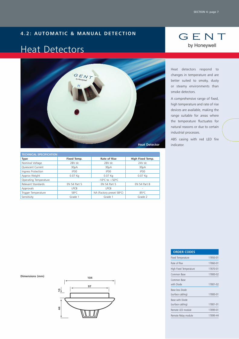
Heat detectors respond to
changes in temperature and are
better suited to smoky, dusty
or steamy environments than
smoke detectors.
A comprehensive range of fixed,
high temperature and rate of rise
devices are available, making the
range suitable for areas where
the temperature fluctuates for
natural reasons or due to certain
industrial processes.
ABS casing with red LED fire
indicator.heat Detector
TEChNICal SpECIFICaTIONType Fixed Temp. rate of rise high Fixed Temp.Nominal Voltage 28V dc 28V dc 24V dc
Quiescent Current 30μA 30μA 30μA
Ingress Protection IP30 IP30 IP30
Approx Weight 0.07 Kg 0.07 Kg 0.07 Kg
Operating Temperature -10oC to +50oC
Relevant Standards EN 54 Part 5 EN 54 Part 5 EN 54 Part 8
Approvals LPCB LPCB -
Trigger Temperature 58oC NA (Factory preset 58oC) 85oC
Sensitivity Grade 1 Grade 1 Grade 2
4 . 2 : au T O M aT I C & M a N ua l D E T E C T I O N
Heat Detectors
97
104
1044
Dimensions (mm)
by Honeywell
SECTION 4: page 8
OrDEr CODES
Beam Detector 07011-41
Reflective Beam 07011-40
Power Supply 05214-24-EN
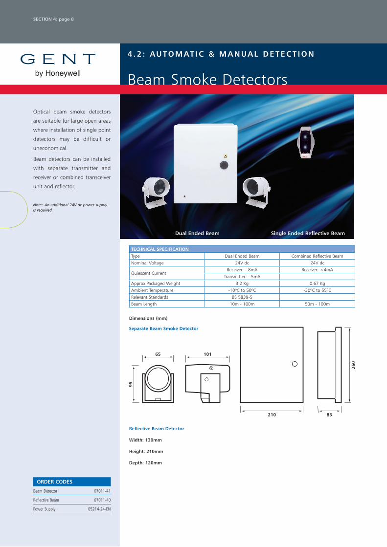
Optical beam smoke detectors
are suitable for large open areas
where installation of single point
detectors may be difficult or
uneconomical.
Beam detectors can be installed
with separate transmitter and
receiver or combined transceiver
unit and reflector.
Note: An additional 24V dc power supply is required.
Single Ended reflective Beam
TEChNICal SpECIFICaTIONType Dual Ended Beam Combined Reflective Beam
Nominal Voltage 24V dc 24V dc
Quiescent CurrentReceiver: - 8mA Receiver: <4mA
Transmitter: - 5mA
Approx Packaged Weight 3.2 Kg 0.67 Kg
Ambient Temperature -10oC to 50oC -30oC to 55oC
Relevant Standards BS 5839-5
Beam Length 10m - 100m 50m - 100m
4 . 2 : au T O M aT I C & M a N ua l D E T E C T I O N
Beam Smoke Detectors
Dimensions (mm)
65 101
210 85
260
95
Separate Beam Smoke Detector
reflective Beam Detector
Width: 130mm
height: 210mm
Depth: 120mm
Dual Ended Beam

by Honeywell
SECTION 4: page 9
OrDEr CODES
Duct Detector
Includes Venturi tube and
Duct Kit Mounting 17815-01
Remote Relay Module 17899-44
Optical Smoke Detector 17840-01
The duct detector kit is comprised
of a conventional detector and
duct detector housing.
The duct detector is mounted
on the outside of the air duct. A
venturi tube protrudes into the
duct and draws a sample of the
air which passes over the sensor
and returns back into the duct.
When the smoke density in the
sampled air reaches the trigger
level of the smoke detector an
alarm will be signalled on the fire
alarm control panel.Duct Detector
TEChNICal SpECIFICaTION
Ingress Protection IP54
Operating Temperature -10oC to +60oC
Approx Weight 0.7Kg
Finish ABS plastic (Grey)
Air Velocity 1M/S to 20M/S
Quiescent Current 90μA
4 . 2 : au T O M aT I C & M a N ua l D E T E C T I O N
Duct Smoke Detector
Dimensions (mm)
300 120
110
by Honeywell
SECTION 4: page 10
OrDEr CODES
low profile Sounder 100 dBa
IP65 Electronic Sounder Red C3IP-SN-R
IP65 Electronic Sounder White C3IP-SN-W
IP31 Electronic Sounder Red C3-SN-R
IP31 Electronic Sounder White C3-SN-W
low profile Sounder and Strobe
100 dBa
IP65 Electronic Sounder/Strobe
Red C3IP-SN-ST-RR
IP65 Electronic Sounder/Strobe
White C3IP-SN-ST-WR
IP31 Electronic Sounder/Strobe
Red C3-SN-ST-RR
IP31 Electronic Sounder/Strobe
White C3-SN-ST-WR
Conventional Strobe
IP65 Ultra Low Current Strobe (5mA)
Red Body/Red Lens C2IP-ST-RR
Please note – all strobes are red except where listed
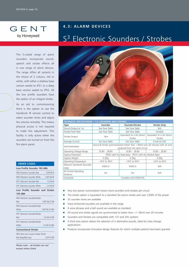
The S-cubed range of alarm
sounders incorporate sound,
speech and strobe effects all
in one range of alarm devices.
The range offers all variants in
the choice of 2 colours, red or
white, with either a shallow base
version sealed to IP31 or a deep
base version sealed to IP55. All
the low profile sounders have
the option of an integral strobe.
As an aid to commissioning
there is the option to use the
HandiLink IR remote control to
select sounder tones and adjust
the volume remotely. This means
physical access is not required
to make this adjustment. This
facility is only active when the
sounders are turned on from the
fire alarm panel.
Very low power consumption means more sounders and strobes per circuit
The strobe option is equivalent to a standard 3w xenon strobe and uses 1/20th of the power
32 sounder tones are available
Voice enhanced sounders are available in the range
4 voice phrases and a bell sound are available as standard
All sound and strobe signals are synchronised to better than +/- 30mS over 20 minutes
Sounders and Strobes are compatible with 12V and 24V systems
A third wire option allows the selection of 2 alternative sounds. Ideal for class change applications
Products incorporate innovative design features for which multiple patents have been granted
4 . 3 : a l a r M D E v I C E S
S3 Electronic Sounders / Strobes
TEChNICal SpECIFICaTION – 1.0. SOuNDErS aND STrOBESType Sounder Sounder/Strobe Strobe OnlySound Output at 1m See Tone Table See Tone Table N/A
Strobe Flash Rate See Tone Table See Tone Table Variable
Strobe Output N/AEquivalent to a 3w Xenon
StrobeEquivalent to a 3w Xenon
Strobe
Average Current See Tone Table See Tone Table 6 mA @ 24V
SynchronisationSound & Strobe synchronisation better than ±30mS over 20 minutes with all units
powered from the same circuit
Operating Voltage Range 10.8V – 28.8V 10.8V – 28.8V 10.8V – 28.8V
Ingress Protection IP55C with the Deep Base IP31C with the Shallow Base
Approx Weight 0.3Kg 0.3Kg 0.3Kg
Operating Temperature -10oC to 50oC -10oC to 50oC -10oC to 50oC
Relevant Standards (Sounder only)
EN54-3 EN54-3 N/A
IR Control Operating Distance
3m 3m N/A
Standards Complies with EN54 Pt3

by Honeywell
SECTION 4: page 11
OrDEr CODES
low profile voice Enhanced Sounder
and Strobe 100 dBa
IP31 Voice Sounder/Strobe Red C3-VP-ST-RR
IP31 Voice Sounder/Strobe White C3-VP-ST-WR
remote Control
HandiLink IR Remote Control for the
S-Cubed range of Sounders S3-CONTROL
how to select a speech message and attention tone
1. Select the required speech message and tone from the signal 1 column of table 3 referring to table 1 and 2 for message and tone descriptions.
2. If the third wire option is used the two alternative messages and ones for your first selection are shown on the right hand side of table 3.
3. After making a selection set the switch SW1 as shown in the SW1 column of table 3.
4 . 3 : a l a r M D E v I C E S
S3 Voice Enhanced Sounders
TEChNICal SpECIFICaTION – 1.1 vOICE ENhaNCED SOuNDErS & STrOBESType voice Enhanced Sounder voice Enhanced Sounder/StrobeSound Output at 1m See Table 3 See Table 3
Strobe Flash Rate See Table 3 See Table 3
Strobe Output Equivalent to a 3w Xenon Strobe
Average Current See Table 3 See Table 3
SynchronisationSound & Strobe synchronisation better than ± 30mS over 20 minutes
with all units powered from the same circuit
Message and Attention Tone Period 10-30 Seconds 10-30 Seconds
Operating Voltage Range 10.8V – 28.8V 10.8V – 28.8V
Maximum Reverse Monitoring Voltage
30V/20μA 30V/20μA
Ingress Protection IP55C with the Deep Base IP31C with the Shallow Base
Approx Weight 0.3 Kg 0.3 Kg
Operating Temperature -10oC to 50oC -10oC to 50oC
IR Control Operating Distance 3m 3m
CONvENTIONal SpEECh SOuNDEr aND STrOBETable 1Message No. Speech Message
M1 Attention please this is an emergency please leave the building by the nearest available exit. (Female voice)
M2 An incident has been reported in this building please await further instructions. (Female voice)
M3 This is a test message no action is required. (Female voice)
M4 This is a fire alarm! Please leave the building immediately by the nearest available exit. (Male voice)
Complex Tone No. Description of Tone
CTOAlarm Bell (equivalent to 8” Solenoid Bell) 12V 105dB(A) @ 1m with strobe 14.2mA (without strobe 4.5mA) 24V 105.5dB(A) @ 1m with strobe 12mA (without strobe 4.5mA)
Standard messages and complex tones (Audio File - PA020001)
Table 2
Tone Description Graphical representation
Tone 1 Alternating tone 800/ 970Hz @ 2Hz – FP 1063.1 Telecoms
Tone 2 Intermittent tone 970Hz @ 1Hz LF back up alarm – BS 5839: Part 1
Tone 3 Intermittent tone 970Hz 0.25s on, 1s off – BS 5839: Part 1
Tone 4 Continuous @ 970Hz - BS 5839: Part 1
Tone 5 Fast sweep 800Hz – 970Hz @ 7Hz – BS 5839: Part 1
Tone 6 Medium sweep 800Hz – 970Hz @ 1Hz – BS 5839: Part 1
Tone 7 Sweep 1200Hz @ 1200Hz -– 500Hz @ 1Hz with 10ms silence – German DIN tone evacuate
Tone 8 Alternating tone 440Hz / 554Hz @ 2Hz – Turn out Sweden
Tone 9 Intermittent tone 1000Hz @ 1Hz – Local warning Sweden
Tone 10 Intermittent Tone 700Hz 4s On, 4s Off – Industrial alarm Germany
Tone 11 Fast whoop 500Hz – 1000Hz @ 7Hz
Tone 12 US temporal tone LF
Tone 13 US temporal tone HF
Tone 14 Define during manufacture – default is a fast siren
Note: Only the messages and complex tones specified in table 1 are applicable to this S-cubed product.
Note: The nominal sound frequencies stated in the table are based on the resonance frequency of the transducer.

by Honeywell
SECTION 4: page 12
OrDEr CODES
IP40 24V dc Electronic Bell Red
30mA 93-95 dBA @ 1M 12141-04
IP41 220/240V ac
Electronic Bell Grey 30mA 12142-59
IP55 24V dc Weather Resistant
Electronic Bell Red 30mA 12143-04
An electronic bell for a wide
range of uses.
Metal casing available in red or
grey finish.
Suitable for semi flush or surface
mounting.
Bell
TEChNICal SpECIFICaTION
Type 24V dc 230V ac
Ingress ProtectionStandard IP40 Standard IP41
Special IP55 Special IP55
Approx Weight 1.1 Kg 1.25 Kg
Operating Temperature Indoor, -10oC to +50oC
Sound Output at 1m 93dB(A) 96dB(A)
Current at Nominal Voltage 30mA 30mA
Relevant Standard EN 54-3
4 . 4 : a N C I l l a r y E q u I p M E N T
Electronic Bells
Dimensions (mm)
155 85
155
130

by Honeywell
SECTION 4: page 13
To ensure fire doors close in
an emergency and prevent the
spread of fire and smoke.
Moulded ABS and steel
enclosure capable of floor or
wall mounting.
Complies with BS 5839-3.
TEChNICal SpECIFICaTIONWall Mounted Wall Mounted Floor Mounted
Type 24V dc 230V ac 24V dc
Approx Weight Door plate, 0.07 Kg Door holder, 0.53 Kg
Current Consumption 21mA 12mA 45mA
Operating Temperature Indoor/Outdoor, -10oC to + 50oC
Nominal Magnetic Pull 112 Newton 200 Newton
Relevent Standard BS 5839- 3
Finish Moulded ABS
4 . 4 : a N C I l l a r y E q u I p M E N T
Door Release
Door holder
Dimensions (mm)
96 45
23
72 d
ia
96
OrDEr CODES
Door holders, Closers, Batteries and
Chargers
Magnet Door Holder
24V dc 22mA 04390-31
Magnet Door Holder
240V ac 17.5mA 04390-55
Door Holder Floor Plate 04390-92
Door Plate Assembly (Spare) 04390-99
Magnet Door Holder Floor Mounted
24V dc 45mA 04390-41
power Supply units for 24v dc Door
holders
Transformer Rectifier 24V dc 0.5A 05106-05
Transformer Rectifier 24V dc 1.5A 05106-15

by Honeywell
SECTION 4: page 14
OrDEr CODES
24V dc DPCO Relay
c/w High Profile Enclosure 19107-52
24V dc Relay Base and Diode 19104-52
Timer Octal Base 2-32 Secs.
DOE 24V dc c/w Base 19106-02
Enclosures and accessories for
relays
High Profile Enclosure with DIN Rail
125x125x100mm 19100-02
Relay enclosure to house
applications involving switching
and timers.
All purpose polycarbonate
construction.
Suitable for activating class
change or ‘start work’ signals.
low profile Enclosure
TEChNICal SpECIFICaTIONCoil Voltage 24V dc
Coil Current 50mA
Contact Rating 240V ac 6A
Contact Rating 24V dc 5A
Profile High
Max. Capacity 4 mini relays
Ingress Protection IP67
Operating Temperature Indoor/Outdoor, 0 - 40oC
4 . 4 : a N C I l l a r y E q u I p M E N T
Relays
Dimensions (mm)
125
125
50
75 25

by Honeywell
SECTION 4: page 15
To supply additional standby
power for control panels or
relays.
Protected against over-voltage
and reverse polarity connections.
Fault monitoring to comply with
BS 5839.
TEChNICal SpECIFICaTION
Mains Input 230V ac 230V ac
Output Current 4A 1A
Output Voltage 27.5V dc
Operating Temperature -10o to +40oC -10o to +50oC
Max. Battery Capacity 2 x 12V/24Ah 2 x 12V/7Ah
Approx Weight 8.5 Kg 7.5Kg
4 . 4 : a N C I l l a r y E q u I p M E N T
Power Supplies
OrDEr CODES
power Supply units (less cells)
24V, 6.0A charger 05214-24EN
24V, 1A Charger 621028
power Supply unit

by Honeywell
SECTION 4: page 16
4 . 5 : M I S C E l l a N E O u S
System Loading Calculator
Zone LoadingTo calculate the zone loading of any system complete the table below and ensure that the grand total does not exceed system limits (Xenex is 3mA per zone).
NO. (a) quIESCENT lOaD (µa) (b) TOTal lOaD (µa) (a x b)
Optical Smoke Detector 60
Fixed Temperature Heat Detector
30
Rate of Rise Heat Detector 30
High Temperature Heat Detector 30
Grand Total
Notes:
1. If detector removal monitoring is required to comply with BS 5839, a detector base with diode should be used and the maximum number of detectors should not exceed 20 per zone.
2. Any number of manual call points may be included in zone calculations.
3. Beam detectors will require a separate power supply.
Sounder Circuit LoadingTo calculate the maximum sounder loading complete the table below and ensure that the grand total does not exceed system limits. (For Xenex; maximum load per circuit is 0.5A. Total load maximum 1A).
NO. (a)OpEraTINg CurrENT (ma) (b)
TOTal lOaD (ma) (a x b)
S-Cubed Sounders and Strobes
*
Sounder Base 18
24V dc Bell 30
S3 Sounder (no Strobe) 2-6 (depending on tone)
S3 Sounder (with Strobe) 5-12 (depending on tone)
Grand Total
*See tone table for specific operating currents (page 17 section 4).
by Honeywell
SECTION 4: page 17
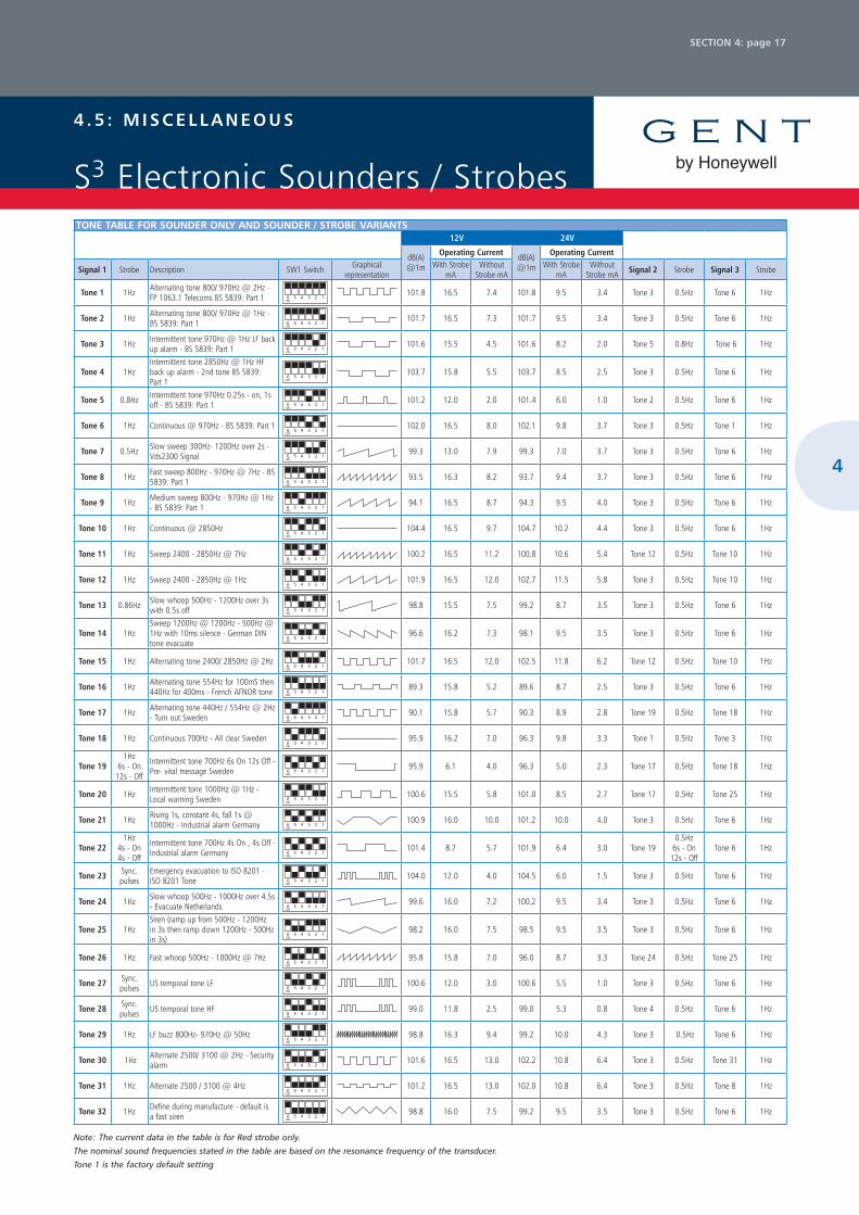
Note: The current data in the table is for Red strobe only.
The nominal sound frequencies stated in the table are based on the resonance frequency of the transducer.
Tone 1 is the factory default setting
4 . 5 : M I S C E l l a N E O u S
S3 Electronic Sounders / StrobesTONE TaBlE FOr SOuNDEr ONly aND SOuNDEr / STrOBE varIaNTS
12V 24V
dB(A) @1m
Operating Current dB(A) @1m
Operating Current
Signal 1 Strobe Description SW1 Switch Graphical representation
With Strobe mA
Without Strobe mA
With Strobe mA
Without Strobe mA Signal 2 Strobe Signal 3 Strobe
Tone 1 1Hz Alternating tone 800/ 970Hz @ 2Hz - FP 1063.1 Telecoms BS 5839: Part 1 6 5 4 3 2 1
ON
101.8 16.5 7.4 101.8 9.5 3.4 Tone 3 0.5Hz Tone 6 1Hz
Tone 2 1Hz Alternating tone 800/ 970Hz @ 1Hz - BS 5839: Part 1 6 5 4 3 2 1
ON
101.7 16.5 7.3 101.7 9.5 3.4 Tone 3 0.5Hz Tone 6 1Hz
Tone 3 1Hz Intermittent tone 970Hz @ 1Hz LF back up alarm - BS 5839: Part 1 6 5 4 3 2 1
ON
101.6 15.5 4.5 101.6 8.2 2.0 Tone 5 0.8Hz Tone 6 1Hz
Tone 4 1Hz Intermittent tone 2850Hz @ 1Hz HF back up alarm - 2nd tone BS 5839: Part 1
6 5 4 3 2 1 ON
103.7 15.8 5.5 103.7 8.5 2.5 Tone 3 0.5Hz Tone 6 1Hz
Tone 5 0.8Hz Intermittent tone 970Hz 0.25s - on, 1s off - BS 5839: Part 1 6 5 4 3 2 1
ON
101.2 12.0 2.0 101.4 6.0 1.0 Tone 2 0.5Hz Tone 6 1Hz
Tone 6 1Hz Continuous @ 970Hz - BS 5839: Part 1 6 5 4 3 2 1 ON
102.0 16.5 8.0 102.1 9.8 3.7 Tone 3 0.5Hz Tone 1 1Hz
Tone 7 0.5Hz Slow sweep 300Hz- 1200Hz over 2s - Vds2300 Signal 6 5 4 3 2 1
ON
99.3 13.0 7.9 99.3 7.0 3.7 Tone 3 0.5Hz Tone 6 1Hz
Tone 8 1Hz Fast sweep 800Hz - 970Hz @ 7Hz - BS 5839: Part 1 6 5 4 3 2 1
ON
93.5 16.3 8.2 93.7 9.4 3.7 Tone 3 0.5Hz Tone 6 1Hz
Tone 9 1Hz Medium sweep 800Hz - 970Hz @ 1Hz - BS 5839: Part 1 6 5 4 3 2 1
ON
94.1 16.5 8.7 94.3 9.5 4.0 Tone 3 0.5Hz Tone 6 1Hz
Tone 10 1Hz Continuous @ 2850Hz 6 5 4 3 2 1 ON
104.4 16.5 9.7 104.7 10.2 4.4 Tone 3 0.5Hz Tone 6 1Hz
Tone 11 1Hz Sweep 2400 - 2850Hz @ 7Hz 6 5 4 3 2 1 ON
100.2 16.5 11.2 100.8 10.6 5.4 Tone 12 0.5Hz Tone 10 1Hz
Tone 12 1Hz Sweep 2400 - 2850Hz @ 1Hz 6 5 4 3 2 1 ON
101.9 16.5 12.0 102.7 11.5 5.8 Tone 3 0.5Hz Tone 10 1Hz
Tone 13 0.86Hz Slow whoop 500Hz - 1200Hz over 3s with 0.5s off 6 5 4 3 2 1
ON
98.8 15.5 7.5 99.2 8.7 3.5 Tone 3 0.5Hz Tone 6 1Hz
Tone 14 1Hz Sweep 1200Hz @ 1200Hz - 500Hz @ 1Hz with 10ms silence - German DIN tone evacuate
6 5 4 3 2 1 ON
96.6 16.2 7.3 98.1 9.5 3.5 Tone 3 0.5Hz Tone 6 1Hz
Tone 15 1Hz Alternating tone 2400/ 2850Hz @ 2Hz 6 5 4 3 2 1 ON
101.7 16.5 12.0 102.5 11.8 6.2 Tone 12 0.5Hz Tone 10 1Hz
Tone 16 1Hz Alternating tone 554Hz for 100mS then 440Hz for 400ms - French AFNOR tone 6 5 4 3 2 1
ON
89.3 15.8 5.2 89.6 8.7 2.5 Tone 3 0.5Hz Tone 6 1Hz
Tone 17 1Hz Alternating tone 440Hz / 554Hz @ 2Hz - Turn out Sweden 6 5 4 3 2 1
ON
90.1 15.8 5.7 90.3 8.9 2.8 Tone 19 0.5Hz Tone 18 1Hz
Tone 18 1Hz Continuous 700Hz - All clear Sweden 6 5 4 3 2 1 ON
95.9 16.2 7.0 96.3 9.8 3.3 Tone 1 0.5Hz Tone 3 1Hz
Tone 19 1Hz
6s - On 12s - Off
Intermittent tone 700Hz 6s On 12s Off - Pre- vital message Sweden 6 5 4 3 2 1
ON
95.9 6.1 4.0 96.3 5.0 2.3 Tone 17 0.5Hz Tone 18 1Hz
Tone 20 1Hz Intermittent tone 1000Hz @ 1Hz - Local warning Sweden 6 5 4 3 2 1
ON
100.6 15.5 5.8 101.0 8.5 2.7 Tone 17 0.5Hz Tone 25 1Hz
Tone 21 1Hz Rising 1s, constant 4s, fall 1s @ 1000Hz - Industrial alarm Germany 6 5 4 3 2 1
ON
100.9 16.0 10.0 101.2 10.0 4.0 Tone 3 0.5Hz Tone 6 1Hz
Tone 22 1Hz
4s - On 4s - Off
Intermittent tone 700Hz 4s On , 4s Off - Industrial alarm Germany 6 5 4 3 2 1
ON
101.4 8.7 5.7 101.9 6.4 3.0 Tone 19 0.5Hz
6s - On 12s - Off
Tone 6 1Hz
Tone 23 Sync. pulses
Emergency evacuation to ISO 8201 - ISO 8201 Tone 6 5 4 3 2 1
ON
104.0 12.0 4.0 104.5 6.0 1.5 Tone 3 0.5Hz Tone 6 1Hz
Tone 24 1Hz Slow whoop 500Hz - 1000Hz over 4.5s - Evacuate Netherlands 6 5 4 3 2 1
ON
99.6 16.0 7.2 100.2 9.5 3.4 Tone 3 0.5Hz Tone 6 1Hz
Tone 25 1Hz Siren (ramp up from 500Hz - 1200Hz in 3s then ramp down 1200Hz - 500Hz in 3s)
6 5 4 3 2 1 ON
98.2 16.0 7.5 98.5 9.5 3.5 Tone 3 0.5Hz Tone 6 1Hz
Tone 26 1Hz Fast whoop 500Hz - 1000Hz @ 7Hz 6 5 4 3 2 1 ON
95.8 15.8 7.0 96.0 8.7 3.3 Tone 24 0.5Hz Tone 25 1Hz
Tone 27 Sync. pulses US temporal tone LF
6 5 4 3 2 1 ON
100.6 12.0 3.0 100.6 5.5 1.0 Tone 3 0.5Hz Tone 6 1Hz
Tone 28 Sync. pulses US temporal tone HF
6 5 4 3 2 1 ON
99.0 11.8 2.5 99.0 5.3 0.8 Tone 4 0.5Hz Tone 6 1Hz
Tone 29 1Hz LF buzz 800Hz- 970Hz @ 50Hz 6 5 4 3 2 1 ON
98.8 16.3 9.4 99.2 10.0 4.3 Tone 3 0.5Hz Tone 6 1Hz
Tone 30 1Hz Alternate 2500/ 3100 @ 2Hz - Security alarm 6 5 4 3 2 1
ON
101.6 16.5 13.0 102.2 10.8 6.4 Tone 3 0.5Hz Tone 31 1Hz
Tone 31 1Hz Alternate 2500 / 3100 @ 4Hz 6 5 4 3 2 1 ON
101.2 16.5 13.0 102.0 10.8 6.4 Tone 3 0.5Hz Tone 8 1Hz
Tone 32 1Hz Define during manufacture - default is a fast siren 6 5 4 3 2 1
ON
98.8 16.0 7.5 99.2 9.5 3.5 Tone 3 0.5Hz Tone 6 1Hz
4

by Honeywell
SECTION 4: page 18
4 . 5 : M I S C E l l a N E O u S
S3 Voice Enhanced Sounders
TaBlE 3 – TONE / vOICE TaBlE FOr vOICE aND vOICE / STrOBE varIaNTS
Decibel (dBA) and current (mA) values Intermittent 1S On and 1S Off
Signal 1Message Strobe Attention
Tone SW1 Switch 12VdB(A) @1m
With Strobe mA
Without Strobe mA
24VdB(A) @1m
With Strobe mA
Without Strobe mA
Signal 2Message Strobe Attention
ToneSignal 3Message Strobe Attention
Tone
M1 1Hz Tone 1 6 5 4 3 2 1 ON
101.8 16.5 7.4 101.8 9.5 3.4 M2 0.5Hz Tone 2 M3 1Hz Tone 4
M1 1Hz Tone 6 6 5 4 3 2 1 ON
94.1 16.5 8.7 94.3 9.5 4.0 M2 0.5Hz Tone 3 M3 1Hz Tone 4
M1 1Hz Tone 11 6 5 4 3 2 1 ON
95.8 15.8 7.0 96.0 8.7 3.3 Tone 5 0.8Hz Tone 6 M3 1Hz Tone 4
M1 1Hz Tone 5 6 5 4 3 2 1 ON
93.5 16.3 8.2 93.7 9.4 3.7 Tone 3 0.5Hz Tone 6 M3 1Hz Tone 4
M1 1Hz Tone 8 6 5 4 3 2 1 ON
90.1 15.8 5.7 90.3 8.9 2.8 Tone 2 0.5Hz Tone 6 M3 1Hz Tone 4
M1 1Hz Tone 7 6 5 4 3 2 1 ON
96.6 16.2 7.3 98.1 5.5 1.0 Tone 3 0.5Hz Tone 1 M3 1Hz Tone 4
M1 1Hz Tone 12 6 5 4 3 2 1 ON
98.8 16.0 7.5 99.2 9.5 3.5 Tone 3 0.5Hz Tone 6 M3 1Hz Tone 4
M1 1Hz Tone 14 6 5 4 3 2 1 ON
101.8 16.5 7.4 101.8 9.5 3.4 Tone 3 0.5Hz Tone 6 M3 1Hz Tone 14
M4 1Hz Tone 1 6 5 4 3 2 1 ON
94.1 16.5 8.7 96.0 8.7 3.3 Tone 3 0.5Hz Tone 6 M6 1Hz Tone 4
M4 1Hz Tone 6 6 5 4 3 2 1 ON
93.5 16.3 8.2 93.7 9.4 3.7 Tone 3 0.5Hz Tone 6 M6 1Hz Tone 4
M4 1Hz Tone 11 6 5 4 3 2 1 ON
90.1 15.8 5.7 90.3 8.9 2.8 Tone 12 0.5Hz Tone 10 M6 1Hz Tone 4
M4 1Hz Tone 5 6 5 4 3 2 1 ON
96.6 16.2 7.3 98.1 9.5 3.5 Tone 3 0.5Hz Tone 10 M6 1Hz Tone 4
M4 1Hz Tone 8 6 5 4 3 2 1 ON
100.6 12.0 3.0 100.6 5.5 1.0 Tone 3 0.5Hz Tone 6 M6 1Hz Tone 4
M4 1Hz Tone 7 6 5 4 3 2 1 ON
98.8 16.0 7.5 99.2 9.5 3.5 Tone 3 0.5Hz Tone 6 M6 1Hz Tone 4
M4 1Hz Tone 12 6 5 4 3 2 1 ON
Refer to decibel (dBA) and current (mA) values stated in Table 1.
Tone 12 0.5Hz Tone 10 M6 1Hz Tone 4
M4 1Hz Tone 14 6 5 4 3 2 1 ON
Tone 3 0.5Hz Tone 6 M3 1Hz Tone 14
M1 1Hz CT0 6 5 4 3 2 1 ON
Tone 19 0.5Hz Tone 18 M3 1Hz CT0
M1 1Hz CT1 6 5 4 3 2 1 ON
Tone 1 0.5Hz Tone 3 M3 1Hz CT1
M1 1Hz CT2 6 5 4 3 2 1 ON
Tone 17 0.5Hz Tone 18 M3 1Hz CT2
M1 1Hz CT3 6 5 4 3 2 1 ON
Tone 17 0.5Hz Tone 25 M3 1Hz CT3
M1 1Hz CT4 6 5 4 3 2 1 ON
Tone 3 0.5Hz Tone 6 M3 1Hz CT4
M1 1Hz CT5 6 5 4 3 2 1 ON
Tone 19 0.5Hz 6s - On 12s - Off Tone 6 M3 1Hz CT5
M1 1Hz CT6 6 5 4 3 2 1 ON
Tone 3 0.5Hz Tone 6 M3 1Hz CT6
M1 1Hz CT7 6 5 4 3 2 1 ON
Tone 3 0.5Hz Tone 6 M3 1Hz CT7
- 1Hz CT0 6 5 4 3 2 1 ON
Tone 3 0.5Hz Tone 6 - 1Hz CT0
- 1Hz CT1 6 5 4 3 2 1 ON
Tone 24 0.5Hz Tone 25 - 1Hz CT1
- 1Hz CT2 6 5 4 3 2 1 ON
Tone 3 0.5Hz Tone 6 - 1Hz CT2
- 1Hz CT3 6 5 4 3 2 1 ON
Tone 4 0.5Hz Tone 6 - 1Hz CT3
- 1Hz CT4 6 5 4 3 2 1 ON
Tone 3 0.5Hz Tone 6 - 1Hz CT4
- 1Hz CT5 6 5 4 3 2 1 ON
Tone 3 0.5Hz Tone 31 - 1Hz CT5
- 1Hz CT6 6 5 4 3 2 1 ON
Tone 3 0.5Hz Tone 8 - 1Hz CT6
- 1Hz CT7 6 5 4 3 2 1 ON
Tone 3 0.5Hz Tone 6 - 1Hz CT7
TON
E O
Nly
aTT
ENTI
ON
TO
NE
FOll
OW
ED B
y Sp
EEC
h M
ESSa
gES
Note: Only the complex tones (CTn) and speech messages (Mn) specified in Table 1 are valid.
The highlighted row in this table shows the factory default setting of the S-cubed unit.