controls, start-up, operation, service and ... - carrier
TRANSCRIPT

Manufacturer reserves the right to discontinue, or change at any time, specifications or designs without notice and without incurring obligations.Catalog No. 04-53300209-01 Printed in U.S.A. Form 30RB-8T Pg 1 2-21 Replaces: 30RB-7T
Controls, Start-Up, Operation, Service and Troubleshooting
CONTENTSPage
SAFETY CONSIDERATIONS . . . . . . . . . . . . . . . . . . 1GENERAL . . . . . . . . . . . . . . . . . . . . . . . . . . . . . . . . . . 3Conventions Used in This Manual . . . . . . . . . . . . . . 3Basic Control Usage . . . . . . . . . . . . . . . . . . . . . . . . . 3CONTROLS . . . . . . . . . . . . . . . . . . . . . . . . . . . . . . . . 4General . . . . . . . . . . . . . . . . . . . . . . . . . . . . . . . . . . . . 4Main Base Board (MBB) . . . . . . . . . . . . . . . . . . . . . . 4Scroll Protection Module (SPM) . . . . . . . . . . . . . . . . 7Electronic Expansion Valve (EXV) Board . . . . . . . . 7Fan Boards . . . . . . . . . . . . . . . . . . . . . . . . . . . . . . . . 10Reverse Rotation Board . . . . . . . . . . . . . . . . . . . . . . 14Enable-Off-Remote Contact Switch . . . . . . . . . . . . . 14Emergency On/Off Switch . . . . . . . . . . . . . . . . . . . . 14Energy Management Module (EMM) . . . . . . . . . . . . 14Energy Management Module Heat Reclaim . . . . . . 14Local Equipment Network . . . . . . . . . . . . . . . . . . . . 16Board Addresses . . . . . . . . . . . . . . . . . . . . . . . . . . . 16Control Module Communication . . . . . . . . . . . . . . . 16Carrier Comfort Network (CCN) Interface . . . . . . . . 16Configuration Options . . . . . . . . . . . . . . . . . . . . . . . 17Dual Chiller Control . . . . . . . . . . . . . . . . . . . . . . . . . 17Capacity Control . . . . . . . . . . . . . . . . . . . . . . . . . . . . 20Head Pressure Control . . . . . . . . . . . . . . . . . . . . . . . 24High-Efficiency Variable Condenser Fans (HEVCF)
(30RB080-390 with Greenspeed Intelligence) . . . . 26Cooler Pump Control . . . . . . . . . . . . . . . . . . . . . . . . 29Machine Control Methods . . . . . . . . . . . . . . . . . . . . 29Cooling Set Point Selection . . . . . . . . . . . . . . . . . . . 30Temperature Reset . . . . . . . . . . . . . . . . . . . . . . . . . . 31Demand Limit . . . . . . . . . . . . . . . . . . . . . . . . . . . . . . 39Remote Alarm and Alert Relays . . . . . . . . . . . . . . . . 41Broadcast Configuration . . . . . . . . . . . . . . . . . . . . . 41Alarm Control . . . . . . . . . . . . . . . . . . . . . . . . . . . . . . 41PRE-START-UP . . . . . . . . . . . . . . . . . . . . . . . . . . . . . 42System Check . . . . . . . . . . . . . . . . . . . . . . . . . . . . . . 42START-UP . . . . . . . . . . . . . . . . . . . . . . . . . . . . . . . . . 42Actual Start-Up . . . . . . . . . . . . . . . . . . . . . . . . . . . . . 42Operating Limitations . . . . . . . . . . . . . . . . . . . . . . . . 43OPERATION . . . . . . . . . . . . . . . . . . . . . . . . . . . . . . . . 44Sequence of Operation . . . . . . . . . . . . . . . . . . . . . . . 44Dual Chiller Sequence of Operation . . . . . . . . . . . . 44Operating Modes . . . . . . . . . . . . . . . . . . . . . . . . . . . . 45Optional Heat Reclaim Module . . . . . . . . . . . . . . . . 48SERVICE . . . . . . . . . . . . . . . . . . . . . . . . . . . . . . . . . . 52Electronic Expansion Valve (EXV) . . . . . . . . . . . . . . 52
Cooler . . . . . . . . . . . . . . . . . . . . . . . . . . . . . . . . . . . . 55RTPF (Round Tube Plate Fin) Condenser Coil
Maintenance and Cleaning Recommendations 56MCHX Condenser Coil Maintenance and Cleaning
Recommendations . . . . . . . . . . . . . . . . . . . . . . . 58Condenser Fans . . . . . . . . . . . . . . . . . . . . . . . . . . . . 58Refrigerant Circuit . . . . . . . . . . . . . . . . . . . . . . . . . . 58Safety Devices . . . . . . . . . . . . . . . . . . . . . . . . . . . . . 59Relief Devices . . . . . . . . . . . . . . . . . . . . . . . . . . . . . 59Compressors . . . . . . . . . . . . . . . . . . . . . . . . . . . . . . 59MAINTENANCE . . . . . . . . . . . . . . . . . . . . . . . . . . . . 60Recommended Maintenance Schedule . . . . . . . . . 60TROUBLESHOOTING . . . . . . . . . . . . . . . . . . . . . . . 60Alarms and Alerts . . . . . . . . . . . . . . . . . . . . . . . . . . 60Sensors . . . . . . . . . . . . . . . . . . . . . . . . . . . . . . . . . . . 78Thermistors (Tables 51-53) . . . . . . . . . . . . . . . . . . . 78Transducers . . . . . . . . . . . . . . . . . . . . . . . . . . . . . . . 79Service Test . . . . . . . . . . . . . . . . . . . . . . . . . . . . . . . 82APPENDIX A — LOCAL DISPLAY TABLES. . . . . . . . . . 93APPENDIX B — CCN TABLES . . . . . . . . . . . . . . . . . . . . 107APPENDIX C — CCN ALARMS . . . . . . . . . . . . . . . . . . . 124APPENDIX D — R-410A PRESSURE VS.
TEMPERATURE CHART . . . . . . . . . . . . . . . . . . . . . . . 127APPENDIX E — MAINTENANCE SUMMARY AND
LOG SHEETS . . . . . . . . . . . . . . . . . . . . . . . . . . . . . . . . . 128APPENDIX F — BACNET COMMUNICATION OPTION . . . . . . . . . . . . . . . . . . . . . . . . . . . . . . . . . . . . . . 132APPENDIX G — SIEMENS OR SCHNEIDER LOW AMBIENT DRIVES . . . . . . . . . . . . . . . . . . . . . . . . . . . . . 143INDEX . . . . . . . . . . . . . . . . . . . . . . . . . . . . . . . . . . . . . . . . . 150START-UP CHECKLIST FOR 30RB LIQUID CHILLER . . . . . . . . . . . . . . . . . . . . . . . . . . . . . CL-1
SAFETY CONSIDERATIONSInstallation and servicing of air-conditioning equipment can behazardous due to system pressure and electrical components. Onlytrained and qualified service personnel should install, repair, orservice air-conditioning equipment.Untrained personnel can perform basic maintenance functions ofcleaning coils and filters and replacing filters. All other operationsshould be performed by trained service personnel. When workingon air-conditioning equipment, observe precautions in theliterature, tags and labels attached to the unit, and other safetyprecautions that may apply.Follow all safety codes, including ANSI (American NationalStandards Institute) Z223.1. Wear safety glasses and work gloves.Use quenching cloth for unbrazing operations. Have fireextinguisher available for all brazing operations.It is important to recognize safety information. This is the safety-alert symbol . When you see this symbol on the unit and in
AquaSnap®
30RB060-390 Air-Cooled Chillers and30RB080-390 Air-Cooled Chillers with
Greenspeed® Intelligence

2
instructions or manuals, be alert to the potential for personalinjury.Understand the signal words DANGER, WARNING,CAUTION, and NOTE. These words are used with the safety-alert symbol. DANGER identifies the most serious hazards whichwill result in severe personal injury or death. WARNING signifieshazards which could result in personal injury or death. CAUTIONis used to identify unsafe practices, which may result in minorpersonal injury or product and property damage. NOTE is used tohighlight suggestions which will result in enhanced installation,reliability, or operation.
DANGER
DO NOT USE TORCH to remove any component. Systemcontains oil and refrigerant under pressure.To remove a component, wear protective gloves and gogglesand proceed as follows:a. Shut off electrical power to unit.b. Recover refrigerant to relieve all pressure from system
using both high-pressure and low pressure ports.c. Traces of vapor should be displaced with nitrogen and
the work area should be well ventilated. Refrigerant incontact with an open flame produces toxic gases.
d. Cut component connection tubing with tubing cutter andremove component from unit. Use a pan to catch any oilthat may come out of the lines and as a gage for howmuch oil to add to the system.
e. Carefully un-sweat remaining tubing stubs when neces-sary. Oil can ignite when exposed to torch flame.
Failure to follow these procedures may result in personal inju-ry or death.
WARNING
DO NOT VENT refrigerant relief valves within a building.Outlet from relief valves must be vented outdoors in accor-dance with the latest edition of ANSI/ASHRAE (AmericanNational Standards Institute/American Society of Heating,Refrigerating and Air-Conditioning Engineers) 15 (SafetyCode for Mechanical Refrigeration). The accumulation ofrefrigerant in an enclosed space can displace oxygen andcause asphyxiation. Provide adequate ventilation in enclosedor low overhead areas. Inhalation of high concentrations ofvapor is harmful and may cause heart irregularities, uncon-sciousness or death. Misuse can be fatal. Vapor is heavier thanair and reduces the amount of oxygen available for breathing.Product causes eye and skin irritation. Decomposition prod-ucts are hazardous.
WARNING
UNIT OPERATION AND SAFETY HAZARDFailure to follow this warning could cause personal injury,death and/or equipment damage.R-410A refrigerant systems operate at higher pressures thanstandard R-22 systems. Do not use R-22 service equipment orcomponents on R-410A refrigerant equipment.
WARNING
Electrical shock can cause personal injury and death. Shut offall power to this equipment during installation. There may bemore than one disconnect switch. Tag all disconnect locationsto alert others not to restore power until work is completed.
CAUTION
This unit uses a microprocessor control system. Do not shortor jumper between terminations on circuit boards or modules;control or board failure may result.Be aware of electrostatic discharge (static electricity) whenhandling or making contact with circuit boards or module con-nections. Always touch a chassis (grounded) part to dissipatebody electrostatic charge before working inside control center.Use extreme care when handling tools near boards and whenconnecting or disconnecting terminal plugs. Circuit boardscan easily be damaged. Always hold boards by the edges andavoid touching components and connections.This equipment uses, and can radiate, radio frequency energy.If not installed and used in accordance with the instructionmanual, it may cause interference to radio communications. Ithas been tested and found to comply with the limits for a ClassA computing device pursuant to International Standard inNorth America EN 61000-2/3 which are designed to providereasonable protection against such interference when operatedin a commercial environment. Operation of this equipment ina residential area is likely to cause interference, in which casethe user, at his own expense, will be required to take whatevermeasures may be required to correct the interference.Always store and transport replacement or defective boards inanti-static shipping bag.
CAUTION
To prevent potential damage to heat exchanger, always runfluid through heat exchanger when adding or removing refrig-erant charge. Use appropriate brine solutions in cooler fluidloop to prevent the freezing of heat exchanger, optionalhydronic section and/or interconnecting piping when theequipment is exposed to temperatures below 32°F (0°C). Proofof flow switch and strainer are factory installed on all models.Do NOT remove power from this chiller during winter shut-down periods without taking precaution to remove all waterfrom heat exchanger and optional hydronic system. Failure toproperly protect the system from freezing may constitute abuseand may void warranty.
CAUTION
Compressors and optional hydronic system pumps requirespecific rotation. Check reverse rotation board. If lower (red)LED is blinking, the phase sequence is incorrect. Swap anytwo incoming power leads to correct condenser fan rotationbefore starting any other motors. Operating the unit withoutverifying proper phasing could result in equipment damage.
CAUTION
Refrigerant charge must be removed slowly to prevent loss ofcompressor oil that could result in compressor failure.

3
GENERALThis publication contains Controls, Operation, Start-Up, Serviceand Troubleshooting information for the 30RB060-390 air-cooledliquid chillers with electronic controls. The 30RB chillers areequipped with ComfortLink controls and electronic expansionvalves.NOTE: Unit sizes 315-390 are modular units that are shipped inseparate sections as modules A or B as noted in position 8 of theunit model number. Installation directions specific to these unitsare noted in these instructions. For modules 315A, 315B, 330A,330B, 345A, 345B, and 360B, follow all general instructions asnoted for unit sizes 30RB160,170. For modules 360A, 390A, and390B, follow instructions for 30RB190. See Table 1 for a listing ofunit sizes and modular combinations.NOTE: The nameplate for modular units contains only the firsttwo digits in the model number. For example, 315A and 315Bnameplates read 31A and 31B.
Table 1 — Modular Unit Combinations
Conventions Used in This ManualThe following conventions for discussing configuration points forthe local display (scrolling marquee or Navigator™ accessory)will be used in this manual.Point names will be written with the mode name first, then anysub-modes, then the point name, each separated by an arrow sym-bol (. Names will also be shown in bold and italics. As an ex-ample, the Lead/Lag Circuit Select Point, which is located in theConfiguration mode, Option sub-mode, would be written as Con-figuration OPTNLLCS.This path name will show the user how to navigate through the lo-cal display to reach the desired configuration. The user wouldscroll through the modes and sub-modes using the and keys. The arrow symbol in the path name represents pressing
to move into the next level of the menu structure.When a value is included as part of the path name, it will be shownat the end of the path name after an equals sign. If the value rep-resents a configuration setting, an explanation will be shown in pa-renthesis after the value. As an example, ConfigurationOPTNLLCS = 1 (Circuit A leads).Pressing the and keys simultaneously willscroll an expanded text description of the point name or valueacross the display. The expanded description is shown in the localdisplay tables but will not be shown with the path names in text.The CCN (Carrier Comfort Network®) point names are also refer-enced in the local display tables for users configuring the unit with
CCN software instead of the local display. The CCN tables are lo-cated in Appendix B of the manual.
Basic Control UsageSCROLLING MARQUEE DISPLAYThe scrolling marquee display is the standard interface display tothe ComfortLink control system for 30RB units. The display hasup and down arrow keys, an key, and an key.These keys are used to navigate through the different levels of thedisplay structure. Press the key until the highest operat-ing level is displayed to move through the top 11 mode levels indi-cated by LEDs (light-emitting diodes) on the left side of the dis-play. See Fig. 1.Once within a mode or sub-mode, pressing the and
keys simultaneously will put the scrolling marqueedisplay into expanded text mode where the full meaning of allsub-modes, items and their values can be displayed for the currentselection. Press the and keys to return thescrolling marquee display to its default menu of rotating displayitems (those items in Run StatusVIEW). In addition, the pass-word will be disabled, requiring that it be entered again beforechanges can be made to password protected items. Press the
key to exit out of the expanded text mode.
Fig. 1 — Scrolling Marquee Display
NOTE: When the Language Selection (ConfigurationDISPLANG), variable is changed, all appropriate display ex-pansions will immediately change to the new language. No pow-er-off or control reset is required when reconfiguring languages.When a specific item is located, the item name alternates with thevalue. Press the key at a changeable item and the valuewill be displayed. Press again and the value will beginto flash indicating that the value can be changed. Use the up anddown arrow keys to change the value, and confirm the value bypressing the key.Changing item values or testing outputs is accomplished in thesame manner. Locate and display the desired item. Press
so that the item value flashes. Use the arrow keys tochange the value or state and press the key to accept it.Press the key to return to the next higher level of struc-ture. Repeat the process as required for other items.Items in the Configuration and Service Test modes are passwordprotected. The words ‘PASS’ and ‘WORD’ will alternate on thedisplay when required. The default password is 0111. Press
and the 1111 password will be displayed. Press again and the first digit will begin to flash. Use the ar-
row keys to change the number and press to accept thedigit. Continue with the remaining digits of the password. Thepassword can only be changed through CCN operator interfacesoftware such as ComfortWORKS®, ComfortVIEW™ and Ser-vice Tool. See Table 2 and Appendix A for further details.
CAUTION
DO NOT re-use compressor oil or any oil that has been ex-posed to the atmosphere. Dispose of oil per local codes andregulations. DO NOT leave refrigerant system open to air anylonger than the actual time required to service the equipment.Seal circuits being serviced and charge with dry nitrogen toprevent oil contamination when timely repairs cannot be com-pleted. Failure to follow these procedures may result in dam-age to equipment.
UNIT SIZE MODULE A MODULE B30RB315 30RB160 30RB16030RB330 30RB170 30RB16030RB345 30RB170 30RB17030RB360 30RB190 30RB17030RB390 30RB190 30RB190
ENTER
ESCAPE ENTER
ENTER ESCAPE
ESCAPE
ENTERESCAPE
ENTER ESCAPE
ESCAPE
Run Status
Service Test
Temperature
Pressures
Setpoints
Inputs
Outputs
Configuration
Time Clock
Operating Modes
Alarms
Alarm Status
ENTER
MODE
ESCAPE
ENTERENTER
ENTER
ENTERENTER
ESCAPE
ENTERENTER
ENTER

4
ACCESSORY NAVIGATOR™ DISPLAY MODULEThe Navigator module provides a mobile user interface to theComfortLink control system, which is only available as a field-in-stalled accessory. The display has up and down arrow keys, an
key, and an key. These keys are used to nav-igate through the different levels of the display structure. Press the
key until ‘Select a Menu Item’ is displayed to movethrough the top 11 mode levels indicated by LEDs on the left sideof the display. See Fig. 2..
Fig. 2 — Accessory Navigator Display Module
Once within a Mode or sub-mode, a “>” indicates the currently se-lected item on the display screen. Pressing the and
keys simultaneously will put the Navigator moduleinto expanded text mode where the full meaning of all sub-modes,items and their values can be displayed. Pressing the and keys when the display says ‘Select Menu Item’(Mode LED level) will return the Navigator module to its defaultmenu of rotating display items (those items in Run Sta-tusVIEW). In addition, the password will be disabled, requiringthat it be entered again before changes can be made to passwordprotected items. Press the key to exit out of the ex-panded text mode.NOTE: When the Language Selection (ConfigurationDISPLANG), variable is changed, all appropriate display ex-pansions will immediately change to the new language. No pow-er-off or control reset is required when reconfiguring languages. When a specific item is located, the item name appears on the leftof the display, the value will appear near the middle of the displayand the units (if any) will appear on the far right of the display.Press the key at a changeable item and the value will be-gin to flash. Use the up and down arrow keys to change the value,and confirm the value by pressing the key.Changing item values or testing outputs is accomplished in thesame manner. Locate and display the desired item. Press so that the item value flashes. Use the arrow keys to change thevalue or state and press the key to accept it. Press the
key to return to the next higher level of structure. Re-peat the process as required for other items.Items in the Configuration and Service Test modes are passwordprotected. The words Enter Password will be displayed when re-quired, with 1111 also being displayed. The default password is0111. Use the arrow keys to change the number and press
to enter the digit. Continue with the remaining digits ofthe password. The password can only be changed through CCNoperator interface software such as ComfortWORKS™, Comfort-VIEW™ and Service Tool.
Adjusting the ContrastThe display contrast can be adjusted to suit ambient conditions.To adjust the contrast of the Navigator module, press the
key until the display reads, “Select a menu item.”Using the arrow keys move to the Configuration mode. Press
to obtain access to this mode. The display will read:> TEST OFFMETR OFFLANG ENGLISH
Pressing will cause the “OFF” to flash. Use the up ordown arrow to change “OFF” to “ON.” Pressing will il-luminate all LEDs and display all pixels in the view screen. Press-ing and simultaneously allows the user toadjust the display contrast. Use the up or down arrows to adjustthe contrast. The screen’s contrast will change with the adjust-ment. Press to accept the change. The Navigator modulewill keep this setting as long as it is plugged in to the LEN (localequipment network) bus.Adjusting the Backlight BrightnessThe display backlight can be adjusted to suit ambient conditions.The factory default is set to the highest level. To adjust the Navi-gator module backlight, press the key until the displayreads, “Select a menu item.” Using the arrow keys move to theConfiguration mode. Press to obtain access to thismode. The display will read:
> TEST OFFMETR OFFLANG ENGLISH
Pressing will cause “OFF” to flash. Use the up or downarrow keys to change “OFF” to “ON.” Pressing will il-luminate all LEDs and display all pixels in the view screen. Press-ing up and down arrow keys simultaneously adjusts the displaybrightness. Use the up or down arrow keys to adjust screen bright-ness. Press to accept the change. The Navigator modulewill keep this setting as long as it is plugged in to the LEN bus.
CONTROLS
GeneralThe 30RB air-cooled liquid chillers contain the ComfortLink elec-tronic control system that controls and monitors all operations ofthe chiller. The control system is composed of several componentsas listed in the following sections. All machines have at the veryleast a main base board (MBB), scrolling marquee display, electricexpansion valve board (EXV), fan board, one scroll protectionmodule (SPM) per compressor, Emergency On/Off switch, an En-able-Off- Remote Contact switch and a reverse rotation board.
Main Base Board (MBB)The MBB is the heart of the ComfortLink control system, whichcontains the major portion of operating software and controls theoperation of the machine. See Fig. 3. The MBB continuouslymonitors input/output channel information received from its in-puts and from all other modules. The MBB receives inputs fromstatus and feedback switches, pressure transducers and thermis-tors. The MBB also controls several outputs. Some inputs and out-puts to control the machine are located on other boards, but aretransmitted to or from the MBB via the internal communicationsbus. Information is transmitted between modules via a 3-wirecommunication bus or LEN. The CCN bus is also supported. Con-nections to both LEN and CCN buses are made at TB3. For acomplete description of main base board inputs and outputs andtheir channel identifications, see Table 3.
ENTER ESCAPE
ESCAPE
Run StatusService TestTemperaturesPressures
SetpointsInputs
OutputsConfigurationTime Clock
Operating ModesAlarms
ENTER
ESC
MODEAlarm Status
ComfortLink
ENTERESCAPE
ENTERESCAPE
ESCAPE
ENTER
ENTER
ENTER
ENTERESCAPE
ENTER
ESCAPE
ENTER
ENTERENTER
ENTER ESCAPE
ENTER
ESCAPE
ENTER
ENTERENTER
ENTER

5
Table 2 — ComfortLink Display Menu Structure
Fig. 3 — Main Base Board
MODERUN
STATUSSERVICE
TEST TEMPERATURE PRESSURE SETPOINTS INPUTS OUTPUTS CONFIGURATION TIME
CLOCKOPERATING
MODES ALARMS
AutoDisplay(VIEW)
ManualTest Mode
(TEST)
UnitTemperatures
(UNIT)
Circuit APressures(PRC.A)
CoolingSetpoints(COOL)
GeneralInputs
(GEN.I)
Circuit AOutputs(CIR.A)
DisplayConfiguration
(DISP)Time of Day
(TIME)
OperatingControlType
(SLCT)
ResetCurrentAlarms
(R.ALM)Remote
UserInterface(R.CCN)
QuickTestMode
(QUIC)
Circuit ATemperatures
(CIR.A)
Circuit BPressures(PRC.B)
HeatingSetpoints(HEAT)
Circuit BOutputs(CIR.B)
UnitConfiguration
(UNIT)Day, Date(DATE)
OperatingModes
(MODE)
CurrentAlarms(ALRM)
MachineStarts/Hours(RUN)
Circuit BTemperatures
(CIR.B)
Circuit CPressures(PRC.C)
Misc. Setpoints(MISC)
Circuit COutputs(CIR.C)
ServiceConfigurations
(SERV)Schedule 1
(SCH1)AlarmHistory
(H.ALM)
CompressorRun Hours
(HOUR)
Circuit CTemperatures
(CIR.C)
GeneralOutputs(GEN.O)
OptionsConfiguration
(OPTN)Schedule 2
(SCH2)
CompressorStarts
(STRT)
Reset, Demand Limit, Master/Slave
(RSET)Holidays(HOLI)
Fan RunHours(FAN)
ServiceMaintenanceConfiguration
(MCFG)Compressor
Disable(CP.UN)
PredictiveMaintenance
(MAIN)SoftwareVersions(VERS)
221221
221221
195
195
195
195
195
195
195
CH
1C
H2
CH
3C
H4
CH11 CH12
LOCATION OFSERIAL NUMBER
CH13 CH14 CH15A
J4ANALOGINPUTSJ3
J2CJ2BJ15
J1A
J9D
+ G –
DISCRETEINPUTS
J5A
C16A
CH15BC
CCH16B
11 C16J2A
TR1 TR2 TR3 TR4 TR5
CH19 CH20 CH21 CH22 CH23 CH24 CH25 CH26
J8
CH17 CH18
J5B J5C
TH
ER
MIS
TOR
S
PR
ES
SU
RE
S
CH
5C
H6
CH
7C
H8
CH
9
J7A
J7B
J7C
J7D
RELAYOUTPUTS
MOV1
C41 C42 C43
C32 C33 C34 C35
12/1112/11
J1019 J12
J13 + G -
STATUS
J9A
K1 K2D15
J6
CCN
CH10
+ G –SIO
(LEN)
J9C J9B
+ G –

6
Table 3 — Main Base Board Inputs and Outputs
* Controls discharge and liquid line isolation solenoids for 30RB120-190brine units only.
DESCRIPTION INPUT/OUTPUT I/O TYPE SCROLLING MARQUEEPOINT NAME
CONNECTION POINTPin Notation
Power (24 vac supply) — — —MBB-J1A, MBB-J1B11 24 vac12 Ground
Local Equipment Network — — —
MBB-J9A, MBB-J9B, MBB-J9C, MBB-J9D+G-
Carrier Comfort Network® (CCN) — — —
MBB-J12+G-
External Chilled Water Pump Interlock PMPI Switch INPUTSGEN.ILOCK MBB-J4-CH15A
Chilled Water Flow Switch CWFS Switch INPUTSGEN.ILOCKMBB-J5A-CH15B
15BDemand Limit Switch #1 Demand Limit SW1 Switch INPUTSGEN.IDLS1 MBB-J4-CH13
Circuit A Discharge Pressure Transducer DPTA Pressure Transducer
(0-5 VDC) PRESSUREPRC.ADP.A
MBB-J7A-CH65V 5 vdc Ref.S SignalR Return
Circuit B Discharge Pressure Transducer DPTB Pressure Transducer
(0-5 VDC) PRESSUREPRC.BDP.B
MBB-J7C-CH85V 5 vdc Ref.S SignalR Return
Dual Chiller LWT Thermistor DUAL 5k Thermistor TEMPERATUREUNITCHWS MBB-J6-CH3
Dual Set Point Input Dual Set Point Switch INPUTSGEN.IDUAL MBB-J4-CH12Entering Water Thermistor EWT 5k Thermistor TEMPERATUREUNITEWT MBB-J6-CH2Leaving Water Thermistor LWT 5k Thermistor TEMPERATUREUNITLWT MBB-J6-CH1
Outdoor Air Thermistor OAT 5k Thermistor TEMPERATUREUNITOAT MBB-J6-CH4
Pump #1 InterlockPump #2 Interlock
PMP1PMP2 Switch INPUTSGEN.IPUMP
MBB-J5C-CH1818C
Reverse Rotation Board Reverse Rotation Board Switch INPUTSGEN.IELECMBB-J5A-CH16B
16B
Circuit A Suction Pressure Transducer SPTA Pressure Transducer
(0-5 VDC) PRESSUREPRC.ASP.A
MBB-J7B-CH75V 5 vdc Ref.S SignalR Return
Circuit B Suction Pressure Transducer SPTB Pressure Transducer
(0-5 VDC) PRESSUREPR.BSP.B
MBB-J7D-CH95V 5 vdc Ref.S SignalR Return
Unit Status Remote Contact-Off-Enable Switch INPUTSGEN.IONOF MBB-J4-CH11Alarm Relay ALM R Relay OUTPUTSGEN.OALRM MBB-J3-CH24Alert Relay ALT R Relay OUTPUTSGEN.OALRT MBB-J3-CH25
Cooler Heater CL-HT TRIAC OUTPUTSGEN.OCO.HT MBB-J2B-CH21Circuit A Minimum
Load Control* MLV-A TRIAC OUTPUTSCIR.AHGB.A MBB-J2C-CH22
Circuit B Minimum Load Control* MLV-B TRIAC OUTPUTSCIR.BHGB.B MBB-J2C-CH23
Pump #1 Starter PMP1 TRIAC OUTPUTSGEN.OPMP.1 MBB-J2A-CH19Pump #2 Starter PMP2 TRIAC OUTPUTSGEN.OPMP.2 MBB-J2A-CH20
Ready Relay RDY R Relay OUTPUTSGEN.OREDY MBB-J3-CH26

7
Scroll Protection Module (SPM)There is one SPM per compressor and it is responsible for con-trolling that compressor. See Fig. 4. The device controls the com-pressor contactor and the compressor crankcase heater. The SPMmodule also monitors the compressor motor temperature, and cir-cuit high pressure switch. The SPM responds to commands fromthe MBB (main base board) and sends the MBB the results of thechannels it monitors via the LEN (Local Equipment Network).See below for SPM board address information. See Table 4 forSPM inputs and outputs.
Fig. 4 — Scroll Protection Module
Electronic Expansion Valve (EXV) BoardAt least one EXV board is used in all machines. There is one EXVboard for 2-circuit machines. Three-circuit machines have twoEXV boards. See Fig. 5. The board is responsible for monitoringthe return gas temperature thermistors. The board also signals theEXV motors to open or close. The electronic expansion valveboard responds to commands from the MBB and sends the MBBthe results of the channels it monitors via the LEN (local equip-ment network). See below for DIP switch information for EXV1and EXV2. See Tables 5-6 for EXV inputs and outputs.
SPM-A1 DIP Switch 1 2 3 4 5 6 7 8Address: ON OFF OFF OFF ON OFF OFF OFF
SPM-A2 DIP Switch 1 2 3 4 5 6 7 8Address: OFF ON OFF OFF ON OFF OFF OFF
SPM-A3 DIP Switch 1 2 3 4 5 6 7 8Address: OFF OFF ON OFF ON OFF OFF OFF
SPM-A4 DIP Switch 1 2 3 4 5 6 7 8Address: OFF OFF OFF ON ON OFF OFF OFF
SPM-B1 DIP Switch 1 2 3 4 5 6 7 8Address: ON OFF OFF OFF OFF ON OFF OFF
SPM-B2 DIP Switch 1 2 3 4 5 6 7 8Address: OFF ON OFF OFF OFF ON OFF OFF
SPM-B3 DIP Switch 1 2 3 4 5 6 7 8Address: OFF OFF ON OFF OFF ON OFF OFF
SPM-B4 DIP Switch 1 2 3 4 5 6 7 8Address: OFF OFF OFF ON OFF ON OFF OFF
SPM-C1 DIP Switch 1 2 3 4 5 6 7 8Address: ON OFF OFF OFF OFF OFF ON OFF
SPM-C2 DIP Switch 1 2 3 4 5 6 7 8Address: OFF ON OFF OFF OFF OFF ON OFF
SPM-C3 DIP Switch 1 2 3 4 5 6 7 8Address: OFF OFF ON OFF OFF OFF ON OFF
SPM-C4 DIP Switch 1 2 3 4 5 6 7 8Address: OFF OFF OFF ON OFF OFF ON OFF EXV1 DIP Switch 1 2 3 4
Address: 65 OFF OFF OFF OFF
EXV2 DIP Switch 1 2 3 4Address: 66 ON OFF OFF OFF
1 2 3 4 5 6 7 8
ON
103
103
LOCATION OFSERIAL NUMBER
QC1
QC2
JP4
JP1
JP2
JP5
JP6
D4
C19 D6 D5
Q4
D7
Q5 D9 U3
Q6 D8 Q3
SMD
JP3
F1
C46 D13 D14
LED1 LED2

8
Table 4 — Scroll Protection Module Inputs and Outputs*
* “x” denotes the circuit, A, B or C. “n” denotes the compressor number, 1, 2, 3, or 4.
Table 5 — EXV1 Board Inputs and Outputs
DESCRIPTION INPUT/OUTPUT I/O TYPE SCROLLING MARQUEEPOINT NAME
CONNECTION POINTPin Notation
Power (24 vac supply) — — —SPM-xn-J1
QC1 24 vacQC2 Ground
Local Equipment Network — — —
SPM-xn-JP11 +2 G3 -
SPM-xn-JP22 +3 G4 -
Circuit x High Pressure Switch HPS-x Switch Not availableSPM-xn-JP3
12
Compressor xn Motor Temperature MTR-xn PTC Thermistor Not availableSPM-xn-JP4
12
Compressor xn Contactor Cxn Relay OUTPUTSCIR.xCP.xnSPM-xn-JP5
12
Crankcase Heater CCH Relay OUTPUTSCIR.xHT.xnSPM-xn-JP6
12
Circuit x High Pressure Switch HPS-x Switch Not availableSPM-xn-JP2
1
DESCRIPTION INPUT/OUTPUT I/O TYPE SCROLLING MARQUEEPOINT NAME
CONNECTION POINTPin Notation
Power (24 vac supply) — — —EXV1-J1
11 24 vac12 Ground
Local Equipment Network — — —
EXV1-J41 +2 G3 –
Circuit A Suction Gas Thermistor SGTA 5k Thermistor TEMPERATURECIR.ASGT.AEXV1-J3
THA
Circuit B Suction Gas Thermistor SGTB 5k Thermistor TEMPERATURECIR.BSGT.BEXV1-J3
THB
Circuit A EXV EXV-A Stepper Motor OUTPUTSCIR.AEXV.A
EXV1-J2A1234
Circuit B EXV EXV-B Stepper Motor OUTPUTSCIR.BEXV.B
EXV1-J2B1234

9
Table 6 — EXV2 Inputs and Outputs
NOTE: EXV2 inputs and outputs are only used on 30RB210-300.
Fig. 5 — EXV Board
DESCRIPTION INPUT/OUTPUT I/O TYPE SCROLLING MARQUEEPOINT NAME
CONNECTION POINTPin Notation
Power (24 vac supply) — — —EXV2-J1
11 24 vac12 Ground
Local Equipment Network — ——
EXV2-J41 +2 G3 –
Circuit C Suction Gas Thermistor SGTC 5k Thermistor TEMPERATURECIR.CSGT.CEXV2J3
THA
Circuit C EXV EXV-C Stepper Motor OUTPUTSCIR.CEXV.C
EXV2-J2A1234
NOTE: PIN1 OF EACH CONNECTOR MARKED WITH “1”
ADDRESS DIP SWITCH

10
Fan BoardsAt least one fan board is installed in each unit (see Fig. 6 and 7),except for 30RB080-190 units with the high-efficiency variablecondenser fan (HEVCF) option; fan boards are not used with thisoption on these units. There are two types of fan boards, with andwithout an analog output signal for the low ambient head pressurecontrol fan speed controllers. If a unit does not have low ambienthead pressure control installed, it will not have the analog connec-tion terminals. The fan board responds to commands from theMBB and sends the MBB the results of the channels it monitorsvia the LEN. See below for fan board 1, 2 and 3 DIP switch ad-dresses. See Tables 7-9 for inputs and outputs.
Fig. 6 — Fan Board (AUX 1) with Low Ambient Temperature Head Pressure Control
FAN BOARD 1 DIP Switch 1 2 3 4 5 6 7 8
Address: OFF ON OFF OFF ON OFF ON OFF
FAN BOARD 2 DIP Switch 1 2 3 4 5 6 7 8
Address: ON ON OFF OFF ON OFF ON OFF
FAN BOARD 3 DIP Switch 1 2 3 4 5 6 7 8
Address: OFF OFF ON OFF ON OFF ON OFF
1 2 3 4 5 6 7 8
ON
100K 100K
100K
CH1 CH2 CH3 CH4 CH5 CH6 CH7 CH8
TR1 TR2 TR3 TR4 TR5 TR6 TR7 TR8
STATUS SIO (LEN)
LOCATION OFSERIAL NUMBER
24 VA
CC
H13
CH
14
J9
J1
CH9 CH10 CH11 CH12
JP2
C61 CH13
D12 JP1
L3
L5
U21
L2
D6
D5Q5
Y1
D7
D8
S1
D3
U1
Q1
U5 U
6 U7
U8
U9 Q10
Q11
U10
J4
J3J2
U4
U2
Q12
Q60
3
2
1–
G
+
3
2
1–
G
+
DIP SWITCH
J5
J6
J7J8

11
Table 7 — Fan Board 1 (AUX1, AUX2) Outputs*
*Fan boards 1 and 2 will use the AUX1 board when the low ambienttemperature head pressure control option is installed.†Supplied on AUX1 board only.
NOTES: 1. Fan board 1 is used on 30RB060-390.2. 24 vac TRIAC outputs may indicate 12-13 vac when output is de-
energized.
DESCRIPTION INPUT/OUTPUT I/O TYPE SCROLLING MARQUEEPOINT NAME
CONNECTION POINTPin Notation
Power (24 vac supply) — — —FB1-J1
11 24 vac12 Ground
Local Equipment Network — — —
FB1-J9+G-+G-
Circuit A Low AmbientTemperature Head Pressure
Control Speed SignalMM-A† 0-10 VDC OUTPUTSCIR.ASPD.A
FB1-CH9+-
Circuit B Low Ambient TemperatureHead Pressure Control Speed Signal
(sizes 060-150, 210-250)MM-B† 0-10 VDC OUTPUTSCIR.BSPD.B
FB1-CH10+-
Outdoor Fan Motor 1 OFM1 TRIAC24 VAC
FB1-J2-CH1(sizes 060-110)
FB1-J2-CH2(sizes 120-150, 210-250)
FB1-J2-CH3(sizes 160-190, 275, 300,
Duplex sizes 315-390)
Outdoor Fan Motor 2 OFM2 TRIAC24 VAC
FB1-J2-CH2(sizes 060-110)
FB1-J2-CH3(sizes 120-150, 210-250)
FB1-J2-CH4(sizes 160-190, 275, 300,
Duplex sizes 315-390)
Outdoor Fan Motor 3 OFM3 TRIAC24 VAC
FB1-J2-CH3(sizes 060,070,090-110)
FB1-J3-CH5(size 080)
FB1-J2-CH1(sizes 120-150, 210-250)
FB1-J2-CH2(sizes 160-190, 275, 300,
Duplex sizes 315-390)
Outdoor Fan Motor 4 OFM4 TRIAC24 VAC
FB1-J2-CH4(sizes 060,070,130,
150,210-250)FB1-J3-CH6
(size 080)FB1-J3-CH7
(sizes 090-110)FB1-J3-CH5
(sizes 160-190, 275-300, Duplex sizes 315-390)
Outdoor Fan Motor 5 OFM5 TRIAC24 VAC
FB1-J3-CH5(sizes 090-110)
FB1-J3-CH6(sizes 120-150, 210-250)
FB1-J2-CH1(sizes 160-190, 275-300, Duplex sizes 315-390)
Outdoor Fan Motor 6 OFM6 TRIAC24 VAC
FB1-J3-CH6(sizes 090-110,
160-190, 275-300,Duplex sizes 315-390)
FB1-J3-CH7(sizes 120-150, 210-250)
Outdoor Fan Motor 7 OFM7 TRIAC24 VAC
FB1-J3-CH5(sizes 120-150, 210-250)
Outdoor Fan Motor 8 OFM8 TRIAC24 VAC
FB1-J3-CH8(sizes 120-150, 210-250)

12
Fig. 7 — Fan Board (AUX 2) without Low Ambient Temperature Head Pressure Control
Table 8 — Fan Board 2 (AUX1, AUX2) Outputs*
*Fan boards 1 and 2 will use the AUX1 board when the low ambienttemperature head pressure control option is installed.†Output only on units with low ambient temperature head pressure con-trol installed (AUX1).
NOTES:1. Fan board 2 used on 30RB160-190, 275-300, 315-390.2. 24 vac TRIAC outputs may indicate 12-13 vac when output is de-
energized.
DESCRIPTION INPUT/OUTPUT I/O TYPE SCROLLING MARQUEEPOINT NAME
CONNECTION POINTPin Notation
Power (24 vac supply) — — —FB2-J1
11 24 vac12 Ground
Local Equipment Network — — —
FB2-J9+G-+G-
Circuit B Low Ambient Temperature Head Pressure Control
Speed Signal(sizes 160-190, 275-300, 315-400)
MM-B† 0-10 VDC OUTPUTSCIR.BSPD.BFB2-CH9
+-
Outdoor Fan Motor 7 OFM7† TRIAC24 VAC
FB2-J2-CH2(sizes 160, 170, 315-345, 360B)
FB2-J2-CH3(sizes 190, 275, 300, 360A, 390)
Outdoor Fan Motor 8 OFM8 TRIAC24 VAC
FB2-J2-CH3(sizes 160, 170, 315-345, 360B)
FB2-J2-CH4(sizes 190, 275, 300, 360A, 390)
Outdoor Fan Motor 9 OFM9 TRIAC24 VAC
FB2-J2-CH1(sizes 160, 170, 315-345, 360B)
FB2-J2-CH2(sizes 190, 275, 300, 360A, 390)
Outdoor Fan Motor 10 OFM10 TRIAC24 VAC
FB2-J2-CH4(sizes 160, 170, 315-345, 360B)
FB2-J3-CH5(sizes 190, 275, 300, 360A, 390)
Outdoor Fan Motor 11 OFM11 TRIAC24 VAC
FB2-J2-CH1(sizes 190, 275-300, 360A, 390)
Outdoor Fan Motor 12 OFM12 TRIAC24 VAC
FB2-J3-CH6(sizes 190, 275-300, 360A, 390)
1 2 3 4 5 6 7 8
ON
100K 100K
100K
LOCATION OFSERIAL NUMBER
TR1 TR2 TR3 TR4 TR5 TR6 TR7 TR8
CH1 CH2 CH3 CH4 CH5 CH6 CH7 CH8
STATUS SIO (LEN)
24 VA
C
J1J9
D4
U2
U5
Q2
Q7
Q3
U8
U9
Q9
Q10
Q11
Q12
Q13
J4
J3J2
S1
D7
Q5
Y1
D5
D6
L2
U6
U1
Q1
D3
C3
3
2
1–
G
+
3
2
1–
G
+
DIP SWITCH

13
Table 9 — Fan Board 3 (AUX1) Inputs and Outputs
*Controls discharge and liquid line isolation soleniods for 30RB210-300brine units.†Low ambient temperature head pressure control output is on AUX1board only.
NOTES: 1. Fan board 3 used on 30RB210-300.2. 24 vac TRIAC outputs may indicate 12-13 vac when output is de-
energized.
DESCRIPTION INPUT/OUTPUT I/O TYPE SCROLLING MARQUEEPOINT NAME
CONNECTION POINT(Unit Size)
Pin Notation
Power (24 vac supply) — — —FB3-J1
11 24 vac12 Ground
Local Equipment Network — — —
FB3-J9+G-+G-
Circuit C Discharge Pressure Transducer DPTC Pressure Transducer
(0-5 VDC) PRESSUREPRC.CDP.C FB3-J7-CH13
Circuit C Suction Pressure Transducer SPTC Pressure Transducer
(0-5 VDC) PRESSUREPRC.CSP.C FB3-J8-CH14
Minimum Load Value Circuit C MLV-C* TRIAC OUTPUTSCIR.CHGB.C FB3-J3-CH7
(sizes 210-300)Circuit C Low Ambient
Temperature Head Pressure Control Speed Signal
(sizes 210-300)MM-C† 0-10 VDC OUTPUTSCIR.CSPD.C
FB3-CH9+-
Outdoor Fan Motor 9 OFM9 TRIAC24 VAC
FB3-J2-CH2(sizes 210, 225)
FB3-J2-CH3(size 250)
Outdoor Fan Motor 10 OFM10 TRIAC24 VAC
FB3-J2-CH3(sizes 210, 225)
FB3-J2-CH4(size 250)
Outdoor Fan Motor 11 OFM11 TRIAC24 VAC
FB3-J2-CH1(sizes 210, 225)
FB3-J2-CH2(size 250)
Outdoor Fan Motor 12 OFM12 TRIAC24 VAC
FB3-J2-CH3(sizes 210, 225)
FB3-J2-CH4(size 250)
Outdoor Fan Motor 13 OFM13 TRIAC24 VAC
FB3-J2-CH1(size 250)
FB3-J2-CH2(size 275)
FB3-J2-CH3(size 300)
Outdoor Fan Motor 14 OFM14 TRIAC24 VAC
FB3-J3-CH6(size 250)
FB3-J2-CH3(size 275)
FB3-J2-CH4(size 300)
Outdoor Fan Motor 15 OFM15 TRIAC24 VAC
FB3-J2-CH1(size 275)
FB3-J2-CH2(size 300)
Outdoor Fan Motor 16 OFM16 TRIAC24 VAC
FB3-J2-CH4(size 275)
FB3-J3-CH5(size 300)
Outdoor Fan Motor 17 OFM17 TRIAC24 VAC
FB3-J2-CH1(size 300)
Outdoor Fan Motor 18 OFM18 TRIAC24 VAC
FB3-J3-CH6(size 300)

14
Reverse Rotation BoardThe reverse rotation board monitors the three-phase electrical sys-tem to provide phase reversal, phase loss and under-voltage pro-tection. See Fig. 8. The reverse rotation board has two LEDs(light-emitting diodes) and two adjustable dial settings. Under nor-mal conditions, the upper LED will light up green. The lowerLED is red and will flash (phase reversal) or turn on solid (phaseloss and under-voltage) according to the conditions sensed.DIAL SETTINGSThe reverse rotation board has two dials. See Fig. 8. The upperdial should be set to match the incoming three-phase voltage to thechiller with no compressors running. This dial must be adjustedfor 208/230-v chillers operating on 208-v power supply. The dialshould be adjusted to 200-v minimum setting for this case. Thelower dial is used for trip delay and should be set fully counter-clockwise to the minimum 0.1 second setting.PHASE REVERSAL PROTECTIONThe control monitors the three-phase power sequence supplied atterminals L1, L2, and L3. If the control senses an incorrect phaserelationship, the relay contacts (11/14) on the board will open. Therelay contacts will automatically reset when the correct phase se-quence is applied.PHASE LOSS AND UNDER-VOLTAGE PROTECTIONIf the reverse rotation board senses that any one of the three phaseinputs has no AC voltage or that any one phase has dropped morethan 20% below the voltage dial setting, the relay contacts (11/14)on the board will open. Contacts will reset automatically when allthree phases are present, in the correct sequence and are within thelimits of the voltage dial setting.
NOTE: Normal operation of the reverse rotation board (for exam-ple, no faults are detected) results in a closed contact being appliedto the MBB (plug J5A, channel 16B) through the closed 11/14 re-lay contact.
Enable-Off-Remote Contact SwitchThis switch is installed in all units and provides the owner and ser-vice person with a local means of enabling or disabling the ma-chine. It is a 3-position switch used to control the chiller. Whenswitched to the Enable position the chiller is under its own control.Move the switch to the Off position to shut the chiller down. Movethe switch to the Remote Contact position and a field-installed drycontact can be used to start the chiller. The contacts must be capa-ble of handling a 24-vac, 20-mA load. In the Enable and RemoteContact (dry contacts closed) positions, the chiller is allowed tooperate and respond to the scheduling configuration, CCN config-uration and set point control.
Emergency On/Off SwitchThis switch is installed in all units. The Emergency On/Off switchshould only be used when it is required to shut the chiller off im-mediately. Power to the MBB, energy management module, andscrolling marquee display is interrupted when this switch is offand all outputs from these modules will be turned off.
Fig. 8 — Reverse Rotation Board (RRB)
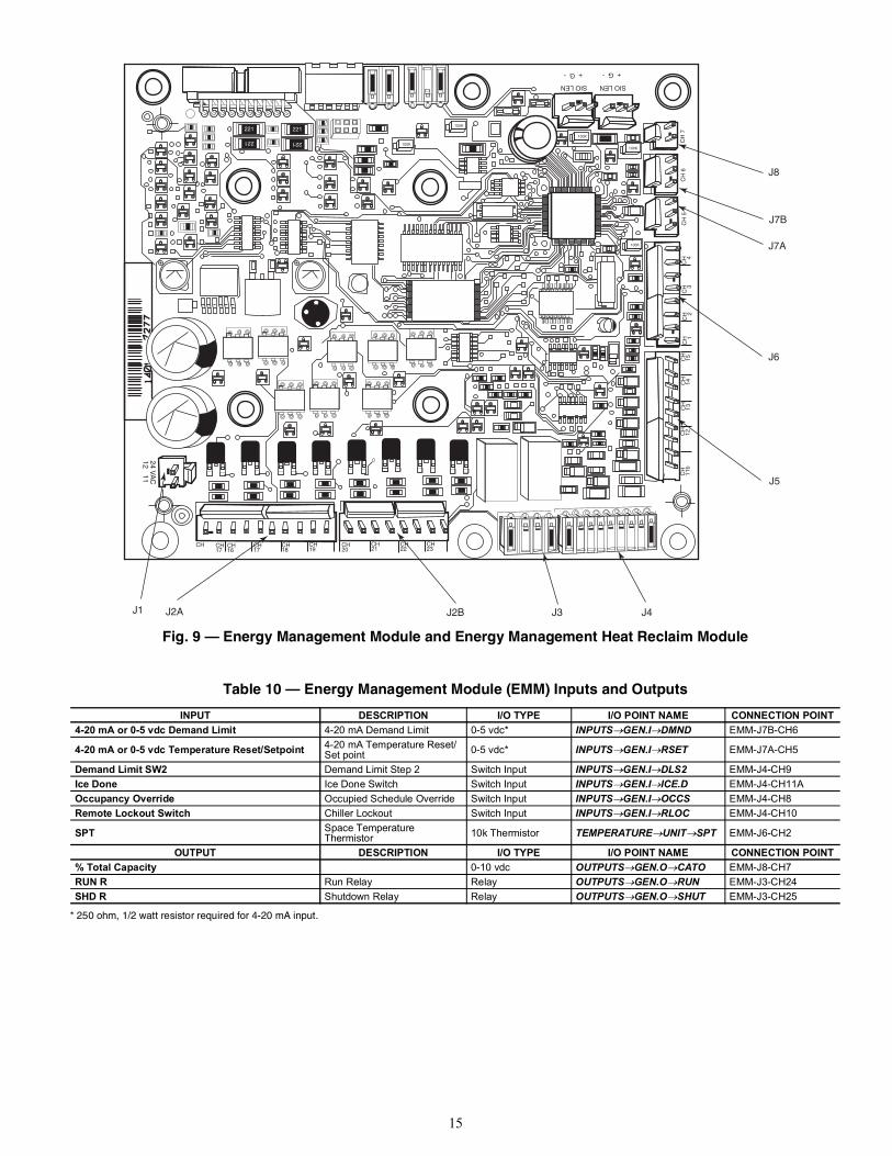
Energy Management Module (EMM)The EMM is available as a factory-installed option or as a field-in-stalled accessory. The EMM receives 4 to 20 mA inputs for thetemperature reset, cooling set point reset and demand limit func-tions. The EMM also receives the switch inputs for the field-in-stalled second stage 2-step or 3-step demand limit, ice done, occu-pancy overrides, and remote lockout functions. The EMM com-municates the status of all inputs with the MBB, and the MBBadjusts the control point, capacity limit, and other functions ac-cording to the inputs received. The EMM generates a 0 to 10 vdcoutput that directly corresponds to the unit percent total capacity.Contacts indicating unit run status and shutdown status are provid-ed. See Table 10 and Fig. 9.
Energy Management Module Heat ReclaimThe EMM HR is available as a factory-installed option. TheEMM HR communicates the status of all of the inputs with theMBB. The MBB then determines the appropriate operating mode.Operating modes are: normal cooling, heat reclaim, and simulta-neous one circuit cooling/one circuit heat reclaim. See Table 11and Fig. 9.
LED STATUS FUNCTION
Upper (green) LED on continuously Relay contacts closed (normal operation)
Lower (red) LED blinking Relay contacts open (phase reversal has occurred)
Lower (red) LED on continuously Relay contacts open (phase loss or under-voltage has occurred)
Upper (green) LED off Power not present at L1, L2, L3 (off)
CAUTION
Care should be taken when interfacing with other manufac-turer’s control systems due to possible power supply differ-ences, full wave bridge versus half wave rectification, whichcould lead to equipment damage. The two different powersupplies cannot be mixed. ComfortLink controls use half waverectification. A signal isolation device should be utilized ifincorporating a full wave bridge rectifier signal generatingdevice is used.
15
Fig. 9 — Energy Management Module and Energy Management Heat Reclaim Module
Table 10 — Energy Management Module (EMM) Inputs and Outputs
* 250 ohm, 1/2 watt resistor required for 4-20 mA input.
INPUT DESCRIPTION I/O TYPE I/O POINT NAME CONNECTION POINT4-20 mA or 0-5 vdc Demand Limit 4-20 mA Demand Limit 0-5 vdc* INPUTSGEN.IDMND EMM-J7B-CH6
4-20 mA or 0-5 vdc Temperature Reset/Setpoint 4-20 mA Temperature Reset/ Set point 0-5 vdc* INPUTSGEN.IRSET EMM-J7A-CH5
Demand Limit SW2 Demand Limit Step 2 Switch Input INPUTSGEN.IDLS2 EMM-J4-CH9Ice Done Ice Done Switch Switch Input INPUTSGEN.IICE.D EMM-J4-CH11AOccupancy Override Occupied Schedule Override Switch Input INPUTSGEN.IOCCS EMM-J4-CH8Remote Lockout Switch Chiller Lockout Switch Input INPUTSGEN.IRLOC EMM-J4-CH10
SPT Space TemperatureThermistor 10k Thermistor TEMPERATUREUNITSPT EMM-J6-CH2
OUTPUT DESCRIPTION I/O TYPE I/O POINT NAME CONNECTION POINT% Total Capacity 0-10 vdc OUTPUTSGEN.OCATO EMM-J8-CH7RUN R Run Relay Relay OUTPUTSGEN.ORUN EMM-J3-CH24SHD R Shutdown Relay Relay OUTPUTSGEN.OSHUT EMM-J3-CH25
221221
221 221
100K
100K
100K
100K
100K
CH17
CH17
CH16
CH CH18
CH19
CH20
CH22
CH21
CH23
24 VA
C12 11 C
H11
bC
H12
CH
13C
H14
CH
15C
H 1C
H 2C
H 3C
H 4C
H 5
CH
6C
H 7
SIO LEN
+ G -+ G -
SIO LEN
J8
J7B
J7A
J6
J5
J4J3J2BJ2AJ1
16
Table 11 — Energy Management Module Heat Reclaim (EMM HR) Inputs and Outputs
Local Equipment NetworkInformation is transmitted between modules via a 3-wire commu-nication bus or LEN (Local Equipment Network). External con-nection to the LEN bus is made at TB3.
Board AddressesAll boards (except the main base board and the energy manage-ment module) have 8-position DIP switches. Addresses for allboards are listed with the input/output tables for each board.
Control Module CommunicationRED LEDProper operation of the control boards can be visually checked bylooking at the red status LEDs (light-emitting diodes). When oper-ating correctly, the red status LEDs will blink in unison at a rate ofonce every 2 seconds. If the red LEDs are not blinking in unison,verify that correct power is being supplied to all modules. Be surethat the MBB is supplied with the current software. If necessary,reload software. If the problem still persists, replace the MBB. Ared LED that is lit continuously or blinking at a rate of once persecond or faster indicates that the board should be replaced.GREEN LEDAll boards have a green LEN (SIO) LED which should beblinking whenever power is on. If the LEDs are not blinkingas described check LEN connections for potential communi-cation errors at the board connectors. See Table 3 for LENconnector designations. A 3-wire bus accomplishes commu-nication between modules. These 3 wires run in parallel from
module to module. The J9A connector on the MBB providescommunication directly to the scrolling marquee display orthe Navigator™ display module.YELLOW LEDThe MBB has one yellow LED. The Carrier Comfort Network®
(CCN) LED will blink during times of network communication.
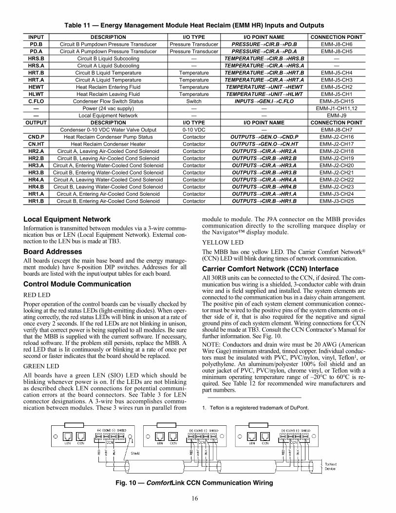
Carrier Comfort Network (CCN) InterfaceAll 30RB units can be connected to the CCN, if desired. The com-munication bus wiring is a shielded, 3-conductor cable with drainwire and is field supplied and installed. The system elements areconnected to the communication bus in a daisy chain arrangement.The positive pin of each system element communication connec-tor must be wired to the positive pins of the system elements on ei-ther side of it, that is also required for the negative and signalground pins of each system element. Wiring connections for CCNshould be made at TB3. Consult the CCN Contractor’s Manual forfurther information. See Fig. 10.NOTE: Conductors and drain wire must be 20 AWG (AmericanWire Gage) minimum stranded, tinned copper. Individual conduc-tors must be insulated with PVC, PVC/nylon, vinyl, Teflon1, orpolyethylene. An aluminum/polyester 100% foil shield and anouter jacket of PVC, PVC/nylon, chrome vinyl, or Teflon with aminimum operating temperature range of –20°C to 60°C is re-quired. See Table 12 for recommended wire manufacturers andpart numbers.
Fig. 10 — ComfortLink CCN Communication Wiring
INPUT DESCRIPTION I/O TYPE I/O POINT NAME CONNECTION POINTPD.B Circuit B Pumpdown Pressure Transducer Pressure Transducer PRESSURECIR.BPD.B EMM-J8-CH6PD.A Circuit A Pumpdown Pressure Transducer Pressure Transducer PRESSURECIR.APD.A EMM-J8-CH5
HRS.B Circuit B Liquid Subcooling — TEMPERATURECIR.BHRS.B —HRS.A Circuit A Liquid Subcooling — TEMPERATURECIR.AHRS.A —HRT.B Circuit B Liquid Temperature Temperature TEMPERATURECIR.BHRT.B EMM-J5-CH4HRT.A Circuit A Liquid Temperature Temperature TEMPERATURECIR.AHRT.A EMM-J5-CH3HEWT Heat Reclaim Entering Fluid Temperature TEMPERATUREUNITHEWT EMM-J5-CH2HLWT Heat Reclaim Leaving Fluid Temperature TEMPERATUREUNITHLWT EMM-J5-CH1C.FLO Condenser Flow Switch Status Switch INPUTSGEN.IC.FLO EMM-J5-CH15
— Power (24 vac supply) — — EMM-J1-CH11,12— Local Equipment Network — — EMM-J9
OUTPUT DESCRIPTION I/O TYPE I/O POINT NAME CONNECTION POINTCondenser 0-10 VDC Water Valve Output 0-10 VDC — EMM-J8-CH7
CND.P Heat Reclaim Condenser Pump Status Contactor OUTPUTSGEN.OCND.P EMM-J2-CH16CN.HT Heat Reclaim Condenser Heater Contactor OUTPUTSGEN.OCN.HT EMM-J2-CH17HR2.A Circuit A, Leaving Air-Cooled Cond Solenoid Contactor OUTPUTSCIR.AHR2.A EMM-J2-CH18HR2.B Circuit B, Leaving Air-Cooled Cond Solenoid Contactor OUTPUTSCIR.BHR2.B EMM-J2-CH19HR3.A Circuit A, Entering Water-Cooled Cond Solenoid Contactor OUTPUTSCIR.AHR3.A EMM-J2-CH20HR3.B Circuit B, Entering Water-Cooled Cond Solenoid Contactor OUTPUTSCIR.BHR3.B EMM-J2-CH21HR4.A Circuit A, Leaving Water-Cooled Cond Solenoid Contactor OUTPUTSCIR.AHR4.A EMM-J2-CH22HR4.B Circuit B, Leaving Water-Cooled Cond Solenoid Contactor OUTPUTSCIR.BHR4.B EMM-J2-CH23HR1.A Circuit A, Entering Air-Cooled Cond Solenoid Contactor OUTPUTSCIR.AHR1.A EMM-J3-CH24HR1.B Circuit B, Entering Air-Cooled Cond Solenoid Contactor OUTPUTSCIR.BHR1.B EMM-J3-CH25
1. Teflon is a registered trademark of DuPont.

17
Table 12 — CCN Communication Bus Wiring
When connecting to a CCN communication bus, use a color-cod-ing scheme for the entire network to simplify the installation. It isrecommended that red be used for the signal positive, black for thesignal negative, and white for the signal ground. Use a similarscheme for cables containing different colored wires. At each system element, tie the shields of its communication buscables together. If the communication bus is entirely within onebuilding, the resulting continuous shield must be connected to aground at one point only. If the communication bus cable exitsfrom one building and enters another, the shields must be connect-ed to grounds at the lightning suppressor in each building wherethe cable enters or exits the building (one point per building only).To connect the unit to the network:1. Turn off power to the control box.2. Cut the CCN wire and strip the ends of the red (+), white
(ground), and black (–) conductors. (Substitute appropriatecolors for different colored cables.)
3. Connect red wire to (+) terminal on TB3 of the plug, whitewire to COM terminal, and black wire to the (–) terminal.
4. The RJ14 CCN connector on TB3 can also be used, but isonly intended for temporary connection (for example, a lap-top computer running Service Tool).
Configuration OptionsThe unit Remote-OFF-Enable switch must be in the OFF positionwhile making changes. If the unit switch is not in the OFF position,REJECTED may be displayed on the scrolling marquee display.MINIMUM LOAD CONTROL (ConfigurationUNITHGBP) reduces the capacity of the 30RB chiller below the low-est standard capacity step by use of hot gas bypass. This capacitystep reduction provides more precise control of the leaving watertemperature. The minimum load valve accessory cannot beused on units configured for brine as the cooler fluid type(Configuration→ SERV?→FLUD). Refer to Brine Chiller Oper-ation for additional information.Minimum Load Control can be configured in three different ways.If Minimum Load Control is not used, HGBP must be set to 0. IfHGBP is set to 1, the control will activate the minimum load controlvalve when the machine is started only. This will be the first step ofcapacity. If HGBP is set to 2, all stages of capacity can utilize theminimum load control valve. If HGBP is set to 3, the minimumload control valve will be used only when the circuit has a high pres-sure override active. This will reduce the capacity of the circuit.RAMP LOADING (ConfigurationOPTNRL.S) limits therate of change of leaving fluid temperature. If the unit is in a Cool-ing mode and configured for Ramp Loading, the control makes 2comparisons before deciding to change stages of capacity. Thecontrol calculates a temperature difference between the controlpoint and leaving fluid temperature. If the difference is greaterthan 4°F (2.2°C) and the rate of change (°F or °C per minute) is
more than the configured Cool Ramp Loading (SetpointsCOOLCRMP), the control does not allow any changes to thecurrent stage of capacity.MINUTES OFF TIME (ConfigurationOPTN DELY) is atime delay added to the start when the machine is commanded ON.This is a field configurable item from 1 to 15 minutes. The factorydefault is 1 minute. This feature is useful when multiple units are in-stalled. Staggering the start will reduce the inrush potential.
Dual Chiller ControlThe dual chiller routine is available for the control of two parallelunits supplying chilled fluid on a common loop. This control is de-signed for a parallel fluid flow arrangement only. One chiller mustbe configured as the master chiller, the other as the slave chiller.An additional leaving fluid temperature thermistor (dual chillerLWT) must be installed in the common chilled water piping as de-scribed in the Installation Instructions for both the master andslave chillers. See the Field Wiring section in the 30RB Installa-tion Instructions for dual chiller LWT sensor control wiring. Achilled water flow switch is factory-installed for each chiller. Parallel chiller control with dedicated pumps is recommended.Chiller must start and stop its own water pump located on its ownpiping. If pumps are not dedicated for each chiller, chiller isolationvalves are required: each chiller must open and close its own isola-tion valve through the control (valve shall be connected to thepump outputs). Pump Control is enabled as described in the Cool-er Pump Control section on page 29. One additional parameter isset for the dual chiller control. Lag Unit Pump Select (Configura-tionRSET LAGP) allows the user to configure the control toenergize the pump for the lag chiller once the unit enters an occu-pied time period or delay the control until the lag chiller is started.It is recommended that this parameter be set to 0, OFF IF UNITSTOPPED. The control of the slave chiller is directed throughcommands emitted by the master chiller. The slave chiller has noaction in master/slave operations; it shall only verify that CCNcommunication with its master is present. See the Dual Chiller Se-quence of Operation section on page 44.Use dual chiller control to designate a lead chiller between themaster and slave chiller. Configure the Lead/Lag Balance Select(ConfigurationRSETLLBL) to ENBL to base the selectionon the Lead/Lag Balance Delta (Configuration RSETLLBD) between the master and slave run hours. If the run hourdifference between the master and the slave remains less thanLLBD, the chiller designated as the lead will remain the leadchiller. The Lead/Lag changeover between the master and theslave chiller due to hour balance will occur during chiller operat-ing odd days, such as day 1, day 3, and day 5 of the month, at12:00 a.m. If a lead chiller is not designated, the master chiller willalways be designated the lead chiller.The dual chiller control algorithm has the ability to delay the startof the lag chiller in two ways. The Lead Pulldown Time (Configu-rationRSETLPUL) provides a field configurable time delayof 0 to 60 minutes. This time delay gives the lead chiller a chanceto remove the heat that the chilled water loop picked up while be-ing inactive during an unoccupied period. The Lead PulldownTime parameter is a one-time delay initiated after starting the leadchiller, manually or by a schedule, before checking whether tostart an additional chiller. This routine provides the lead chiller anopportunity to pull down the loop temperature before starting an-other chiller. The second time delay, Lead/Lag Delay (Configura-tion RSETLLDY) is a time delay imposed between the laststage of the lead chiller and the start of the lag chiller. This pre-vents enabling the lag chiller until the lead/lag delay timer has ex-pired. See Tables 13 and 14.The Lag Unit Pump Select configuration must be set consistently. Ifpump control is NOT being used, set ConfigurationRSETLAGP to 1. If pump control IS being used, set ConfigurationRSETLAGP to 0, which is the default value. This must be set inboth the master and slave chillers, and it must be consistent in both.
MANUFACTURER PART NUMBERRegular Wiring Plenum Wiring
Alpha 1895 —American A21451 A48301Belden 8205 884421Columbia D6451 —Manhattan M13402 M64430Quabik 6130 —
Important: A shorted CCN bus cable will prevent some rou-tines from running and may prevent the unit from starting. Ifabnormal conditions occur, disconnect the CCN bus. If condi-tions return to normal, check the CCN connector and cable.Run new cable if necessary. A short in one section of the buscan cause problems with all system elements on the bus.

18
Table 13 — Configuring the Master Chiller
NOTE: Bold values indicate sub-mode level.
MODE KEYPAD ENTRY DISPLAY ITEM EXPANSION COMMENT
CONFIGURATION
DISP
UNIT
SERV
OPTN
CCNA CCN Address Confirm address of chiller. The master and slave chiller must have different addresses.
1 Factory default address is 1.
CCNA
CCNB CCN Bus Number Confirm the bus number of the chiller. The master and slave chiller must be on the same bus.
0 Factory default is 0.
CCNB
OPTN
RSET Reset Cool and Heat Tmp
CRST Cooling Reset Type
x 5 MSSL Master/Slave Select
0 Disable
0 Disable Flashing to indicate Edit mode. May require Password.
1 Master Use up arrows to change value to 1.
1 Accepts the change.
MSSL
SLVA Slave Address
1
1 Flashing to indicate Edit mode.
2 Use up arrows to change value to 2. This address must match the address of the slave chiller.
2 Accepts the change.
SLVA
LLBL Lead/Lag Balance Select
ENBL Factory Default is ENBL
LLBL
LLBD Lead/Lag Balance Delta
168 Factory Default is 168.
LLBD
LLDY Lead/Lag Start Delay
10 Factory Default is 10.
LLDY
LAGP Lag Unit Pump Select
0 Off if U Stp Factory Default is 0, Off if unit is stopped. Master and slave chiller must be configured to the same value.
LAGP
LPUL Lead Pulldown Time
0 Factory Default is 0.
At mode level.
OPERATINGMODES
SLCT
OPER Operating Control Type
0 Switch Control Master chiller should be configured for job requirements, Switch Control, Time Schedule, or CCN.
At mode level.
ENTER
ENTER
ENTER
ESCAPE
ENTER
ESCAPE
ESCAPE
ENTER
ENTER
ENTER
ENTER
ESCAPE
ENTER
ENTER
ENTER
ESCAPE
ENTER
ESCAPE
ENTER
ESCAPE
ENTER
ESCAPE
ENTER
ESCAPE
ENTER
ESCAPE
ESCAPE
ENTER
ENTER
ENTER
ESCAPE

19
Table 14 — Configuring the Slave Chiller
NOTE: Bold values indicate sub-mode level.
MODE KEYPAD ENTRY DISPLAY ITEM EXPANSION COMMENT
CONFIGURATION
DISP
UNIT
SERV
OPTN
CCNA CCN Address Confirm address of chiller. The master and slave chiller must have different addresses.
1 Factory default address is 1. The slave chiller address must match what was programmed in the Master Chiller SLVA item.
1 Flashing to indicate Edit Mode.
2 This item must match Master Chiller SLVA item.
2 Accepts the change.
CCNA
CCNB CCN Bus Number Confirm the bus number of the chiller. The master and slave chiller must be on the same bus.
0 Factory default bus number is 0.
CCNB
OPTN
RSET Reset Cool and Heat Tmp
CRST Cooling Reset Type
x 5 MSSL Master/Slave Select
0 Disable
0 Disable Flashing to indicate Edit mode. May require Password
2 Slave Use up arrows to change value to 2.
2 Accepts the change.
MSSL
SLVA Slave Address Not required.
LLBL Lead/Lag Balance Select Not required.
LLBD Lead/Lag Balance Delta Not required.
LLDY Lead/Lag Start Delay Not required.
LAGP Lag Unit Pump Select Must be configured to the same value as the master chiller.
LPUL Lead Pulldown Time Not required.
At mode level
OPERATING MODES
SLCT
OPER Operating Control Type
0 Switch Control
0 Flashing to indicate Edit Mode.
2 CCN Control Use up arrows to change value to 2. NOTE: Slave chiller must be configured for CCN.
2 Accepts the value.
OPER
At mode level
ENTER
ENTER
ENTER
ENTER
ENTER
ESCAPE
ENTER
ESCAPE
ESCAPE
ENTER
ENTER
ENTER
ENTER
ESCAPE
ESCAPE
ESCAPE
ENTER
ENTER
ENTER
ENTER
ENTER
ESCAPE
ESCAPE

20
Capacity ControlThe control system cycles compressors and minimum load valvesolenoids (if equipped) to maintain the user-configured leavingchilled fluid temperature set point. Entering fluid temperature isused by the main base board (MBB) to determine the temperaturedrop across the cooler and is used in determining the optimumtime to add or subtract capacity stages. Entering fluid temperature,space temperature (requires additional sensor), or outdoor-air tem-perature reset features can automatically reset the leaving chilledfluid temperature set point. It can also be reset from an external 4to 20-mA signal (requires energy management module).The control has an automatic lead-lag feature built in for circuitand compressor starts. If enabled, the control will determine whichcircuit (ConfigurationOPTNLLCS=0) and compressor tostart to even the wear. The compressor wear factor (combinationof starts and run hours) is used to determine which compressorstarts.Compressor Wear Factor = (Compressor Starts) + 0.1 (Compres-sor Run Hours)In this case, the circuit with the lowest average compressor wearfactor (the average of the wear factors of all available compressorsin the circuit) is the circuit that starts first. The compressor withinthe circuit with the lowest wear factor is the first to start. If the au-tomatic lead-lag function for the circuit is not enabled [Configura-tionOPTNLLCS=1 (Circuit A leads), 2 (Circuit B leads), or3 (Circuit C leads)], then the selected circuit will be the first tostart. Again, the compressor with the lowest wear factor within thecircuit will be the first to start. If Minimum Load Control is en-abled (ConfigurationUNITHGBP=1), the valve will be op-erational only during the first stage of cooling.Once the lead compressor has been started, the lag compressorswill be determined by the wear factor and loading sequence select-ed. If equal loading is selected, (ConfigurationOPTNLOAD=0), the circuit with the lowest average wear factor for theavailable compressors will start next, with the compressor with thelowest wear factor starting. The control will attempt to keep allcircuits at approximately the same number of compressors ON.For this option to function properly, all circuits must have thesame number of compressors available. If a circuit compressor isnot available due to an alarm condition or demand limit, the ca-pacity staging will change to staged. If staged loading is selected,(ConfigurationOPTNLOAD=1), the started circuit will con-tinue to turn on compressors according to the lowest wear factoruntil all are on, then start the next circuit with the lowest averagewear factor. If Minimum Load Control is enabled for close control(ConfigurationUNITHGBP=2), the valve will be availableat all stages for better temperature control. If Minimum Load Con-trol is enabled for high ambient control (ConfigurationUNITHGBP=3), the valve will be used only when a high pres-sure override is active for that circuit.
The electronic expansion valves provide a controlled start-up.During start-up, the low pressure logic in the lead circuit will beignored for 5 minutes to allow for the transient changes duringstart-up. As additional stages of compression are required, the pro-cessor control will add them. The following example is based on a30RB225 machine, which has three 25-ton compressors in eachcircuit. See Table 15.Each example below has different configurations and is intendedto illustrate the loading sequences possible for normal operation.In Example 1 (Table 16), assume the following configurations arein place:ConfigurationUNITHGBP=1 Minimum Load Control in-
stalled and enabled forStart-Up Only
ConfigurationOPTNLOAD=0 Equal Circuit LoadingConfigurationOPTNLLCS=0 Automatic Circuit SelectSince Circuit A has the lowest average wear factor, it will be thelead circuit. Within the circuit, compressor A3 has the lowest wearfactor and will start first with Minimum Load Control ON. Thenext stage will turn OFF the minimum load control. Stage 3 willstart another circuit because of the Equal Circuit Loading configu-ration. The next circuit with the lowest wear factor is Circuit B,and the compressor with the lowest wear factor is B2. The nextstage will be a circuit C compressor. The process continues untilall compressors are ON. See Table 16.In Example 2 (Table 17), assume the compressor starts and runhours are the same as in the previous example and the followingconfigurations are in place:ConfigurationUNITHGBP=1 Minimum Load Control in-
stalled and enabled forStart-Up Only
ConfigurationOPTNLOAD=1 Staged Circuit LoadingConfigurationOPTNLLCS=0 Automatic Circuit SelectSince Circuit A has the lowest average wear factor, it will be thelead circuit. Within the circuit, compressor A3 has the lowest wearfactor and will start first with Minimum Load Control ON. Thenext stage will turn OFF the minimum load control. Stage 3 willstart a compressor in the same circuit because of the Staged Cir-cuit Loading configuration. Compressor A2 has the next lowestwear factor and will be started next. Compressor A3 will be nextto start. Since all compressors in Circuit A are ON, the next stagewill start another circuit. Of the remaining circuits, Circuit B hasthe lowest wear factor, and the compressor with the lowest wearfactor is B2. All of the Circuit B compressors will be started in thesame manner as Circuit A. Once all Circuit B compressors areON, then Circuit C will be started. The process continues until allcompressors are ON. See Table 17.
Table 15 — Compressor Starts and Run Hours
COMPRESSOR STARTS RUN HOURS WEAR FACTOR CIRCUIT AVERAGEWEAR FACTOR
A1 25 249 49.944.8A2 22 237 45.7
A3 26 128 38.8B1 41 453 86.3
67.6B2 38 138 51.8B3 35 297 64.7C1 93 103 103.3
80.3C2 57 98 66.8C3 61 99 70.9

21
Table 16 — Compressor Stages and Circuit Cycling, Example 1
LEGEND NOTES:1. Total Cap. (Total Unit Capacity) and Cir. Cap. (Circuit Capacity) are
approximate percentage values.2. Example is to determine minimum load control, staged circuit load-
ing, and automatic circuit select.
Table 17 — Compressor Stages and Circuit Cycling, Example 2
LEGEND NOTES:1. Total Cap. (Total Unit Capacity) and Cir. Cap. (Circuit Capacity) are
approximate percentage values.2. Example is to determine minimum load control, staged circuit load-
ing, and automatic circuit select.
In Example 3 (Table 18), assume the following configurations arein place:ConfigurationUNITHGBP=1 Minimum Load Control
installed and enabled forStart-Up Only
ConfigurationOPTNLOAD=0 Equal Circuit LoadingConfigurationOPTNLLCS=2 Circuit B LeadsSince Circuit B has been selected, it will be the lead circuit. Withinthe circuit, compressor B2 has the lowest wear factor and will startfirst with Minimum Load Control ON. The next stage will turnOFF the minimum load control. Stage 3 will start another circuitbecause of the Equal Circuit Loading configuration. ComparingCircuit A and C, the circuit with the lowest average wear factor isCircuit A, and the compressor with the lowest wear factor is A3.The next stage will be a circuit C compressor. The process contin-ues until all compressors are ON. See Table 18.In Example 4 (Table 19), assume the compressor starts and runhours are the same as in the first example and the following con-figurations are in place:ConfigurationUNITHGBP=1 Minimum Load Control
installed and enabled forStart-Up Only
ConfigurationOPTNLOAD=1 Staged Circuit LoadingConfigurationOPTNLLCS=3 Circuit C Leads
Since Circuit C has been selected, it will be the lead circuit. Withinthe circuit, compressor C2 has the lowest wear factor and will startfirst with Minimum Load Control ON. The next stage will turnOFF the minimum load control. Stage 3 will start a compressor inthe same circuit because of the Staged Circuit Loading configura-tion. Compressor C3 has the next lowest wear factor and will bestarted next. Compressor C1 will be next to start. Since all com-pressors in Circuit C are ON, the next stage will start another cir-cuit. Of the remaining circuits, Circuit A has the lowest wear fac-tor, and the compressor with the lowest wear factor is A3. All ofthe Circuit A compressors will be started in the same manner asCircuit C. Once all Circuit A compressors are ON, then Circuit Bwill be started. The process continues until all compressors areON. See Table 19.If the circuit capacity is to be reduced, the compressor with thehighest wear factor will be shut off first (in most cases). WithEqual Circuit Loading, stages will be removed from each circuit,following the same criteria used in the loading sequence, but in theopposite order. Shown in Table 19 based on the current wear fac-tor in the opposite to the loading sequence shown above, the com-pressor with the highest wear factor will be removed first. WhenStaged Circuit Loading is selected, the capacity from the last lagcircuit will be removed first.
STAGE TOTALCAP.
CIRCUIT A CIRCUIT B CIRCUIT CCir. Cap. MLC A1 A2 A3 Cir.
Cap. MLC B1 B2 B3 Cir. Cap. MLC C1 C2 C3
0 0 0 0 01 8 24 X X 0 02 11 33 X 0 03 22 33 X 33 X 04 33 33 X 33 X 33 X5 44 66 X X 33 X 33 X6 55 66 X X 66 X X 33 X7 66 66 X X 66 X X 66 X X8 77 100 X X X 66 X X 66 X X9 88 100 X X X 100 X X X 66 X X
10 100 100 X X X 100 X X X 100 X X X
MLC — Minimum Load Control
STAGE TOTALCAP.
CIRCUIT A CIRCUIT B CIRCUIT CCir. Cap. MLC A1 A2 A3 Cir.
Cap. MLC B1 B2 B3 Cir. Cap. MLC C1 C2 C3
0 0 0 0 01 8 24 X X 0 02 11 33 X 0 03 22 66 X X 0 04 33 100 X X X 0 05 44 100 X X X 33 X 06 55 100 X X X 66 X X 07 66 100 X X X 100 X X X 08 77 100 X X X 100 X X X 33 X9 88 100 X X X 100 X X X 66 X X
10 100 100 X X X 100 X X X 100 X X X
MLC — Minimum Load Control

22
Table 18 — Compressor Stage and Circuit Cycling, Example 3
LEGEND NOTES:1. Total Cap. (Total Unit Capacity) and Cir. Cap. (Circuit Capacity) are
approximate percentage values.2. Example is to determine minimum load control, staged circuit loading,
and automatic circuit select.
Table 19 — Compressor Stage and Circuit Cycling, Example 4
LEGEND NOTES:1. Total Cap. (Total Unit Capacity) and Cir. Cap. (Circuit Capacity) are
approximate percentage values.2. Example is to determine minimum load control, staged circuit loading,
and automatic circuit select.
The capacity control algorithm runs every 30 seconds. The al-gorithm attempts to maintain the Control Point at the desiredset point. Each time it runs, the control reads the entering andleaving fluid temperatures. The control determines the rate atwhich conditions are changing and calculates 2 variables basedon these conditions. Next, a capacity ratio (SM2) is calculatedusing the 2 variables to determine whether or not to make anychanges to the current stages of capacity. This ratio value rang-es from –100 to +100%. If the next stage of capacity is a com-pressor, the control starts (stops) a compressor when the ratioreaches +100% (–100%). If the next stage of capacity is the Minimum Load Control, thecontrol energizes (deenergizes) the Minimum Load Control whenthe ratio reaches +60% (–60%). If installed, the minimum loadvalve solenoid will be energized with the first stage of capacity.The control will also use the minimum load valve solenoid as thelast stage of capacity before turning off the last compressor. If theclose control feature (ConfigurationUNITHGBP=2) is en-abled the control will use the minimum load valve solenoid when-ever possible to fine tune leaving fluid temperature control. A de-lay of 90 seconds occurs after each capacity step change withMinimum Load Control. A delay of 3 minutes occurs after eachcompressor capacity step change.BRINE CHILLER OPERATIONFor chiller sizes 120 to 390 with the factory-installed brine option,discharge and liquid line solenoids are added to all circuits (Circuit
B only for size 120). The control system must be correctly config-ured for proper operation. The minimum load valve option mustbe enabled (ConfigurationUNITHGBP=1) and the fluidtype must be set to medium temperature brine (ConfigurationSERVFLUD=2). The Minimum Load Valve output is usedto control the discharge and liquid line solenoid valves. As a re-sult, Minimum Load Control (Hot Gas Bypass) cannot be utilizedon brine duty chillers. The discharge and liquid line solenoidvalves are wired in parallel so they will both open and close at thesame time. The main function of the solenoid valves is to isolate aportion of the condenser section when only a single compressor isrunning to allow for proper oil return to the compressors. A chartshowing solenoid operation is shown below:
NOTE: Minimum load valve (HGBP) cannot be utilized if fluidtype is set to medium temperature brine (Configuration SERVFLUD=2).
STAGE TOTALCAP.
CIRCUIT A CIRCUIT B CIRCUIT CCir. Cap. MLC A1 A2 A3 Cir. Cap. MLC B1 B2 B3 Cir. Cap. MLC C1 C2 C3
0 0 0 0 01 8 0 X 24 X X 02 11 0 33 X 03 22 33 X 33 X 04 33 33 X 33 X 33 X5 44 33 X 66 X X 33 X6 55 66 X X 66 X X 33 X7 66 66 X X 66 X X 66 X X8 77 66 X X 100 X X X 66 X X9 88 100 X X X 100 X X X 66 X X
10 100 100 X X X 100 X X X 100 X X X
MLC — Minimum Load Control
STAGE TOTALCAP.
CIRCUIT A CIRCUIT B CIRCUIT CCir. Cap. MLC A1 A2 A3 Cir. Cap. MLC B1 B2 B3 Cir. Cap. MLC C1 C2 C3
0 0 0 0 01 8 0 0 24 X X2 11 0 0 33 X3 22 0 0 66 X X4 33 0 0 100 X X X5 44 33 X 0 100 X X X6 55 66 X X 0 100 X X X7 66 100 X X X 0 100 X X X8 77 100 X X X 33 X 100 X X X9 88 100 X X X 66 X X 100 X X X
10 100 100 X X X 100 X X X 100 X X X
MLC — Minimum Load Control
CIRCUIT CAPACITYDISCHARGE/LIQUID SOLENOID VALVE
OPERATIONAll compressors off Solenoids energized
One compressor starting Solenoids deenergized after30-second delay
Two or more compressors running Solenoids energizedReduction from two to one compressor running
Solenoids deenergized with no delay

23
CAPACITY CONTROL OVERRIDESThe following capacity control overrides (Run StatusVIEWCAP.S) will modify the normal operation routine. If any of the fol-lowing override conditions listed below is satisfied, it will deter-mine the capacity change instead of the normal control.Override #1: Cooler Freeze ProtectionThis override attempts to avoid the freeze protection alarm. If theLeaving Water Temperature is less than Brine Freeze Set Point(ConfigurationSERVLOSP) + 2.0°F (1.1°C) then remove astage of capacity.NOTE: The freeze set point is 34°F (1.1°C) for fresh water sys-tems (ConfigurationSERVFLUD=1). The freeze set point isBrine Freeze Set Point (ConfigurationSERV LOSP), forMedium Temperature Brine systems (ConfigurationSERVFLUD=2).Override #2: Circuit A Low Saturated Suction Temperature in CoolingOverride #3: Circuit B Low Saturated Suction Temperature in CoolingOverride #4: Circuit C Low Saturated Suction Temperature in CoolingThese overrides attempt to avoid the low suction temperaturealarms. This override is active only when more than one compres-sor in a circuit is ON. If the Saturated Suction Temperature is lessthan Brine Freeze Set Point (ConfigurationSERVLOSP)–18.0°F (–10°C) for 90 seconds, or the Saturated Suction Tem-perature is less than –4°F (–20°C), a compressor in the affectedcircuit will be turned off.Override #5: Low Temperature CoolingThis override removes one stage of capacity when the differencebetween the Control Point (Run StatusVIEWCTPT) and theLeaving Water Temperature (Run StatusVIEWLWT) reach-es a predetermined limit and the rate of change of the water is 0 orstill decreasing.Override #6: Low Temperature CoolingThis override removes two stages of capacity when the EnteringWater Temperature (Run StatusVIEWEWT) is less than theControl Point (Run StatusVIEWCTPT.)Override #7: Ramp LoadingIf the unit is configured for ramp loading (Configura-tionOPTNRL.S=ENBL) and if the difference between theLeaving Water Temperature and the Control Point is greater than4º F (2.2º C) and the rate of change of the leaving water is greaterthan Cool Ramp Loading Rate (SetpointsCOOLCRMP) thenno capacity stage increase will be made. Operating mode 5(MD05) will be in effect.Override #8: Service Manual Test OverrideThe manual test consists in adding a stage of capacity every 30seconds, until the control enables all of the requested compressorsand Minimum Load Control selected in the ComfortLink displayService Test menu. All safeties and higher priority overrides aremonitored and acted upon. Override # 9: Demand LimitThis override mode is active when a command to limit the capaci-ty is received. If the current unit capacity is greater than the activecapacity limit value, a stage is removed. If the current capacity islower than the capacity limit value, the control will not add a stagethat will result in the new capacity being greater then the capacitylimit value. Operating mode 4 (MD04) will be in effect.Override #10: Cooler Interlock OverrideThis override prohibits compressor operation until the Cooler In-terlock (InputsGEN.ILOCK) is closed.Override #11: High Temperature CoolingThis override algorithm runs once when the unit is switched toON. If the difference between the Leaving Water Temperature
(Run Status VIEWLWT) and the Control Point (Run StatusVIEWCTPT) exceeds a calculated value and the rate ofchange of the water temperature is greater than –0.1°F/min, astage will be added.Override #12: High Temperature CoolingThis override runs only when Minimum Load Control is Enabled(ConfigurationUNITHGBP = 1, 2 or 3). This override willadd a stage of capacity if the next stage is Minimum Load Control,when the difference between the Leaving Water Temperature(Run StatusVIEWLWT) and the Control Point (Run Sta-tusVIEWCTPT) exceeds a calculated value and the rate ofchange of the water temperature is greater than a fixed value.Override #13: Minimum On/Off and Off/On Time DelayWhenever a capacity step change has been made, either with Min-imum Load Control or a compressor, the control will remain atthis capacity stage for the next 90 seconds. During this time, nocapacity control algorithm calculations will be made. If the capac-ity step is a compressor, an additional 90-second delay is added tothe previous hold time (see Override #22). This override allowsthe system to stabilize before another capacity stage is added or re-moved. If a condition of a higher priority override occurs, thehigher priority override will take precedence.Override #14: Slow Change OverrideThis override prevents compressor stage changes when the leav-ing temperature is close to the control point and slowly moving to-wards the control point.Override #15: System Manager Capacity ControlIf a Chillervisor module is controlling the unit and the Chillervisormodule is controlling multiple chillers, the unit will add a stage toattempt to load to the demand limited value.Override #16: Circuit A High Pressure OverrideOverride #17: Circuit B High Pressure OverrideOverride #18: Circuit C High Pressure OverrideThis override attempts to avoid a high pressure failure. The algo-rithm is run every 4 seconds. At least one compressor must be onin the circuit. If the Saturated Condensing Temperature for the cir-cuit is above the High Pressure Threshold (ConfigurationSERVHP.TH) then a compressor for that circuit will be re-moved. If Minimum Load Control was enabled for High Ambient(ConfigurationUNITHGBP=3), then the Minimum ControlValve will be energized.Override #19: Standby ModeThis override algorithm will not allow a compressor to run if theunit is in Standby mode, (Run StatusVIEWHC.ST=2).Override #22: Minimum On Time DelayIn addition to Override #13 Minimum On/Off and Off/On TimeDelay, for compressor capacity changes, an additional 90-seconddelay will be added to Override #13 delay. No compressor will bedeenergized until 3 minutes have elapsed since the last compressorhas been turned ON. When this override is active, the capacitycontrol algorithm calculations will be performed, but no capacityreduction will be made until the timer has expired. A control withhigher precedence will override the Minimum On Time Delay.Override #23: Circuit A Low Saturated Suction Temperature in CoolingOverride #24: Circuit B Low Saturated Suction Temperature in CoolingOverride #25: Circuit C Low Saturated SuctionTemperature in CoolingIf the circuit is operating in an area close to the operational limit ofthe compressor, the circuit capacity will remain at the same pointor unload to raise the saturated suction temperature. This algo-rithm will be active if at least one compressor in the circuit is onand one of the following conditions is true:1. Saturated Suction Temperature is less than Brine Freeze
(ConfigurationSERVLOSP) – 6ºF (3.3ºC).

24
2. Saturated Suction Temperature is less than Brine Freeze(ConfigurationSERVLOSP) and the circuit approach(Leaving Water Temperature – Saturated Suction Tempera-ture) is greater than 15ºF (8.3ºC) and the Circuit Superheat(Return Gas Temperature – Saturated Suction Temperature)is greater than 15ºF (8.3ºC).NOTE: The freeze set point is 34ºF (1.1ºC) for fresh watersystems (ConfigurationSERVFLUD=1). The freezeset point is Brine Freeze Set Point (Configura-tionSERVLOSP), for Medium Temperature Brinesystems (ConfigurationSERVFLUD=2).
If any of these conditions are met, the appropriate operating mode,21 (Circuit A), 22 (Circuit B) or 23 (Circuit C) will be in effect.Override #26: Circuit A Operation Outside CompressorOperating EnvelopeOverride #27: Circuit B Operation Outside CompressorOperating EnvelopeOverride #28: Circuit C Operation Outside CompressorOperating EnvelopeThis override prevents compressor operation outside of its operat-ing envelope.1. If the mean saturated discharge temperature (SDT) is greater
than 7°F (3.9°C) over the limit, the circuit is unloaded imme-diately.
2. If the mean SDT is over the limit (but not greater than 7°F(3.9°C) over the limit) for 90 seconds, then the circuit isunloaded.
3. If the mean SDT is more than the limit minus 2°F (1.1°C), thecircuit is prevented from loading. This override shall remainactive until the mean pressure goes below the limit minus 3°F(1.7°C).
Override #34: Circuit A Low Refrigerant ChargeOverride #35: Circuit B Low Refrigerant ChargeOverride #36: Circuit C Low Refrigerant ChargeThe capacity override attempts to protect the compressor fromstarting with no refrigerant in the circuit. This algorithm runs onlywhen the circuit is not operational, (no compressors ON). Thereare several criteria that will enable this override:1. The Saturated Suction Temperature or Saturated Discharge
Temperature is less than –13°F (–10.6°C).2. All of these conditions must be true:
a. The Saturated Suction Temperature or Saturated Dis-charge Temperature is less than Leaving Water Tem-perature by more than 5.4ºF (3.0ºC).
b. Saturated Suction Temperature or Saturated Dis-charge Temperature is less than 41°F (5°C).
c. Outdoor Air Temperature is less than 32°F (0ºC). d. Saturated Suction Temperature or Saturated Dis-
charge Temperature is less than the Outdoor Air Tem-perature by more than 5.4º F (3.0ºC).
3. All of these conditions must be true: a. The Saturated Suction Temperature or Saturated Dis-
charge Temperature is less than Leaving Water Tem-perature by more than 5.4ºF (3.0ºC).
b. Saturated Suction Temperature or Saturated Dis-charge Temperature is less than 41ºF (5ºC).
c. Saturated Suction Temperature or Saturated Dis-charge Temperature is less than the Brine Freeze Point(ConfigurationSERVLOSP) by more than 6ºF(3.3ºC).
NOTE: The freeze set point is 34ºF (1.1ºC) for fresh watersystems (ConfigurationSERVFLUD=1). The freezeset point is Brine Freeze Set Point (Configura-tionSERV LOSP), for Medium Temperature Brinesystems (ConfigurationSERVFLUD=2).
4. All of these conditions must be true: a. The Saturated Suction Temperature or Saturated Dis-
charge Temperature is less than Leaving Water Tem-perature by more than 5.4ºF (3.0ºC).
b. Saturated Suction Temperature or Saturated Dis-charge Temperature is less than 41º F (5º C).
c. Saturated Suction Temperature or Saturated Dis-charge Temperature is less than the Outdoor Air Tem-perature by more than 9ºF (5ºC).
If any of these conditions 1, 2, 3 or 4 are met, the appropriate oper-ating mode, 21 (Circuit A), 22 (Circuit B) or 23 (Circuit C) will bein effect.Override #37: Circuit A Low SuperheatOverride #38: Circuit B Low SuperheatOverride #39: Circuit C Low Superheat This override attempts to avoid liquid slugging for the runningcompressors. It also protects against operation with excessivelyhigh superheat. No capacity steps will be added to the affected cir-cuit until there is a superheat greater than 5ºF (2.8ºC) and less than45ºF (25ºC). If the capacity of the machine must be increased, thecontrol will look to another circuit for additional capacity.
Head Pressure ControlSTANDARD UNITThe main base board (MBB) controls the condenser fans to main-tain the lowest condensing temperature possible, and thus thehighest unit efficiency. The MBB uses the saturated condensingtemperature input from the discharge pressure transducer to con-trol the fans. Head pressure control is maintained through a calcu-lated set point which is automatically adjusted based on actual sat-urated condensing and saturated suction temperatures so that thecompressor(s) is (are) always operating within the manufacturer’sspecified envelope (see Fig. 11). Each time a fan is added the cal-culated head pressure set point will be raised 25°F (13.9°C) for 35seconds to allow the system to stabilize. The control will automat-ically reduce the unit capacity as the saturated condensing tem-perature approaches an upper limit. See capacity overrides 16-18.The control will indicate through an operating mode that high am-bient unloading is in effect. If the saturated condensing tempera-ture in a circuit exceeds the calculated maximum, the circuit willbe stopped. For these reasons, there are no head pressure controlmethods or set points to enter. The control will turn off a fan stagewhen the condensing temperature is below the minimum headpressure requirement for the compressor. Fan sequences areshown in Fig. 12.
Fig. 11 — Compressor Operating Envelope
706050403020100-10-20-30Evaporating Temperature (°F)
60
70
80
90
100
110
120
130
140
150
160
Con
dens
ing
Tem
pera
ture
(°F)

25
Fig. 12 — Condenser Fan Staging (Standard Unit)
MODEL CIRCUIT FANS/CKT LOCATION
FAN STAGE
1 2 3 4 5
30RB060,070,080
060,070
A 3Fan Number FM1 FM2 FM3 — —
Fan Board/Channel FB1/CH1 FB1/CH2 FB1/CH3 — —
B 1Fan Number FM4 — — — —
Fan Board/Channel FB1/CH5 — — — —
080
A 2Fan Number FM1 FM2 — — —
Fan Board/Channel FB1/CH1 FB1/CH2 — — —
B 2Fan Number FM3 FM4 — — —
Fan Board/Channel FB1/CH5 FB1/CH6 — — —
30RB090,100,110
090,100,110
A 3Fan Number FM1 FM2 FM3 — —
Fan Board/Channel FB1/CH1 FB1/CH2 FB1/CH3 — —
B 3Fan Number FM5 FM6 FM4 — —
Fan Board/Channel FB1/CH5 FB1/CH6 FB1/CH7 — —
30RB120
120
A 3Fan Number FM3 FM1 FM2 — —
Fan Board/Channel FB1/CH1 FB1/CH2 FB1/CH3 — —
B 4Fan Number FM7 FM5 FM8 FM6 —
Fan Board/Channel FB1/CH5 FB1/CH6 FB1/CH7 FB1/CH8 —
30RB130,150
130,150
A 4Fan Number FM3 FM1 FM4 FM2 —
Fan Board/Channel FB1/CH1 FB1/CH2 FB1/CH3 FB1/CH4 —
B 4Fan Number FM7 FM5 FM8 FM6 —
Fan Board/Channel FB1/CH5 FB1/CH6 FB1/CH7 FB1/CH8 —
30RB160,170
160,170
A 6Fan Number FM5 FM3 FM1 FM4 FM6 FM2
Fan Board/Channel FB1/CH1 FB1/CH2 FB1/CH3 FB1/CH4 FB1/CH5
B 4Fan Number FM9 FM7 FM10 FM8 —
Fan Board/Channel FB2/CH1 FB2/CH2 FB2/CH3 FB2/CH4 —
30RB190,210,225
190
A 6Fan Number FM5 FM3 FM1 FM4 FM6 FM2
Fan Board/Channel FB1/CH1 FB1/CH2 FB1/CH3 FB1/CH4 FB1/CH5
B 6Fan Number FM11 FM9 FM7 FM10
FM12 FM8
Fan Board/Channel FB2/CH1 FB2/CH2 FB2/CH3 FB2/CH4 FB2/CH5
210,225
A 4Fan Number FM3 FM1 FM4 FM2 —
Fan Board/Channel FB1/CH1 FB1/CH2 FB1/CH3 FB1/CH4 —
B 4Fan Number FM7 FM5 FM8 FM6 —
Fan Board/Channel FB1/CH5 FB1/CH6 FB1/CH7 FB1/CH8 —
C 4Fan Number FM11 FM9 FM12 FM10 —
Fan Board/Channel FB3/CH1 FB3/CH2 FB3/CH3 FB3/CH4 —
30RB250
250
A 4Fan Number FM3 FM1 FM4 FM2 —
Fan Board/Channel FB1/CH1 FB1/CH2 FB1/CH3 FB1/CH4 —
B 4Fan Number FM7 FM5 FM8 FM6 —
Fan Board/Channel FB1/CH5 FB1/CH6 FB1/CH7 FB1/CH8 —
C 6Fan Number FM13 FM11 FM9 FM12
FM14 FM10
Fan Board/Channel FB3/CH1 FB3/CH2 FB3/CH3 FB3/CH4 FB3/CH5
30RB275
275
A 6Fan Number FM5 FM3 FM1 FM4 FM6 FM2
Fan Board/Channel FB1/CH1 FB1/CH2 FB1/CH3 FB1/CH4 FB1/CH5
B 6Fan Number FM11 FM9 FM7 FM10
FM12 FM8
Fan Board/Channel FB2/CH1 FB2/CH2 FB2/CH3 FB2/CH4 FB2/CH5
C 4Fan Number FM15 FM13 FM16 FM14 —
Fan Board/Channel FB3/CH1 FB3/CH2 FB3/CH3 FB3/CH4 —
30RB300
300
A 6Fan Number FM5 FM3 FM1 FM4 FM6 FM2
Fan Board/Channel FB1/CH1 FB1/CH2 FB1/CH3 FB1/CH4 FB1/CH5
B 6Fan Number FM11 FM9 FM7 FM10
FM12 FM8
Fan Board/Channel FB2/CH1 FB2/CH2 FB2/CH3 FB2/CH4 FB2/CH5
C 6Fan Number FM17 FM15 FM13 FM16
FM18 FM14
Fan Board/Channel FB3/CH1 FB3/CH2 FB3/CH3 FB3/CH4 FB3/CH5
FM1
FM2
CO
NT
RO
LB
OX
FM3
FM4
FM1
CO
NT
RO
LB
OX
FM2
FM3
FM4
FM5
FM6
FM1
CO
NT
RO
LB
OX
FM2
FM3 FM5
FM6
FM7
FM8
FM1
CO
NT
RO
LB
OX
FM2
FM3
FM4
FM5
FM6
FM7
FM8
FM1
CO
NT
RO
LB
OX
FM2
FM3
FM4
FM5
FM6
FM7
FM8
FM9
FM10
FM1
CO
NT
RO
LB
OX
FM2
FM3
FM4
FM5
FM6
FM7
FM8
FM9
FM10
FM11
FM12
FM1
CO
NT
RO
LB
OX
FM2
FM3
FM4
FM5
FM6
FM7
FM8
FM9
FM10
FM11
FM12
FM13
FM14
FM1
CO
NT
RO
LB
OX
FM2
FM3
FM4
FM5
FM6
FM7
FM8
FM9
FM10
FM11
FM12
FM13
FM14
FM15
FM16
FM1
CO
NT
RO
LB
OX
FM2
FM3
FM4
FM5
FM6
FM7
FM8
FM9
FM10
FM11
FM12
FM13
FM14
FM15
FM16
FM17
FM18

26
LOW AMBIENT TEMPERATURE HEAD PRESSURECONTROL OPTIONFor low-ambient operation, the lead fan on a circuit can beequipped with low ambient temperature head pressure control op-tion or accessory. The Danfoss VLT controller adjusts fan speed tomaintain the calculated head pressure set point. Table 20 lists re-quired configurations for Danfoss VLT low ambient head pressurecontrol option.
Table 20 — Danfoss VLT Required Configurations, Low Ambient Head Pressure Control Option
*208/230 v units should be configured for 208 v.
High-Efficiency Variable Condenser Fans (HEVCF)(30RB080-390 with Greenspeed Intelligence)This option controls the speed of all fans for improvement in partload efficiency and sound levels. All fans on a circuit are con-trolled by a VFD and run at the same speed. FAN DRIVE OPERATION The HEVCF option uses Danfoss VLT 102 variable frequencydrives. Drives are connected to the LEN communication bus. Fanspeed is determined by the chiller controller and communicated tothe drive. Table 21 lists required configurations for the DanfossVLT HEVCF option.
Table 21 — Danfoss VLT Required Configurations, HEVCF Option
*208/230 v units should be configured for 208 v.
Fan speed is controlled to maintain SCT set point. The set point iscalculated from conditions and adjusted to the most efficient oper-ating point. Fixed set points are also used at low ambient and tran-sition conditions. If the unit is operated in Service Test mode, theSCT set point is fixed at 125°F (51.7°C) for adjusting charge.Drive parameters are set by the chiller control each time the unitpower is cycled with the exception of the drive address. The driveaddress is set at the factory, but will have to be reset in case ofdrive replacement. Addresses for the drives are shown below:
The address is set using the display on the drive. See drive manualfor detailed instructions. Once the address is set, the power is cy-cled to reset all other parameters in the drive. Other parameters arelisted in Tables 22 and 23 for reference. Drive must be in “Auto”mode to operate. Push the “Auto” button at the bottom of thedrive. The light above it will be on.The 208-230v units with 6 condenser fans per circuit require twodrives to operate the fans. See Table 24. They are set up in a mas-ter/slave configuration. The master drive is connected to the LENbus as described above. The slave drive is not connected to LEN.All parameters must be set manually if the drive is replaced asshown in Table 25. The slave drive does not have an address.Fan motor troubleshooting should be done at the drive. Disconnectpower from unit. Remove the entire front cover. Remove smallerpanel covering terminal block at lower right corner of drive. SeeFig. 13. Each fan wire is connected to a separate terminal. Termi-nals are labeled and color coded to match the fan wires. All termi-nals are connected in parallel. All terminals of a certain color, orlabel, are the same point electrically. Disconnect each fan cableand check resistance of motor. An open or short reading betweenphases or a phase and ground could signify a failed fan motor. Ver-ify reading at motor before replacing. Reconnect wires using colorcoding. Replace terminal block cover, drive cover, and power unitto test fan operation.Drive alarms are shown on the chiller controls as:V0-xx Variable Speed Fan Motor Failure, Circuit AV1-xx Variable Speed Fan Motor Failure, Circuit BV2-xx Variable Speed Fan Motor Failure, Circuit CThe characters “xx” correspond to a specific alarm. Commonalarms are listed in Table 26 with possible causes. For a completelist of alarms and causes, see the drive manual supplied with thechiller.Drives and motors are protected by fuses for short circuit protec-tion. See the Service Test section for details. Fan motor overloadprotection is provided by an overload device internal to the motor.The motor overload responds to a combination of temperature andcurrent. On overload condition, the device breaks all 3 phases tothe motor. It will reset automatically once the motor temperaturecools.NOTE: See Appendix G for Siemens and Schneider low ambientcontrol information.
POINTNAME DESCRIPTION VALUE
VAR.A Nb Fan on Varifan Cir A 1VAR.B Nb Fan on Varifan Cir B 1
VAR.C Nb Fan on Varifan Cir C0 (Unit sizes 060-190 and modular units1 (Unit sizes 210-300 only)
VLT.S VLT Fan Drive Select 1RPM.F VLT Fan Drive RPM 1140FC Factory Country Code 1
VFDV VFD Voltage for USA Nameplate voltage(208,380,460,575)*
POINTNAME DESCRIPTION VALUE
VAR.A Nb Fan on Varifan Cir A No. of fans in cktVAR.B Nb Fan on Varifan Cir B No. of fans in ckt
VAR.C Nb Fan on Varifan Cir C0 (Unit sizes 060-190 and modular unitsNo. of fans in ckt (Unit sizes 210-300 only)
VLT.S VLT Fan Drive Select 2RPM.F VLT Fan Drive RPM 1140
FC Factory Country Code 1
VFDV VFD Voltage for USA Nameplate voltage(208,380,460,575)*
DRIVE ADDRESSDrive Parameter Ckt A Ckt B Ckt C
8-31 181 182 183

27
Table 22 — HEVCF Parameters Reset at Chiller Power Cycle
Table 23 — HEVCF Parameters Common to All Setups
Table 24 — 208-230 v Units with 6-Fan Circuits
Table 25 — HEVCF Parameters for 208-230 v Units with 6 Fans per Circuit
*x = Circuit A, B, or C.†See Drive Address table on page 26.
No. FansPer Circuit
PARAMETER1-20 1-22 1-23 1-24 1-25
Motor Power (kW) Motor Volts Motor Frequency (Hz) Motor Amps (A) Motor Speed (RPM)
1 2.6
208
60
11.9
1140380 6.5460 5.4575 4.3
2 5.2
208
60
23.8
1140380 13.0460 10.8575 8.6
3 7.8
208
60
35.7
1140380 19.5460 16.2575 12.9
4 10.4
208
60
47.6
1140380 26.0460 21.6575 17.2
6 15.6
208
60
71.4
1140380 39.0460 32.4575 25.8
PARAMETER DESCRIPTION SETTING0-02 Motor Speed Unit 1 = Hz1-03 Torque Characteristic 1 = Variable Torque1-73 Flying Restart 1 = Yes1-80 Function Stop 0 = Coast1-90 Motor Temp Protection 0 = No1-91 Motor External Fan 0 = No1-93 Thermistor SRC 0 = No3-03 Max Ref 603-15 SRC Ref #1 1 = AI #533-16 SRC Ref #2 0 = No3-41 Ramp Up 5 = 5 Seconds3-42 Ramp Down 5 = 5 Seconds4-10 Motor Speed Direction 0 = Clockwise4-12 Motor Speed Low Limit 54-14 Motor Speed High Limit 614-16 Torque Limit Mode 2254-18 Current Limit 1104-19 Max Output Freq 615-12 DI #27 0 = No Operation14-01 Switching Frequency 414-03 Overmodulation 1 = Yes14-40 VT Level Zero Mag Level 6614-60 Function at Overtemp 1 = Derate8-04 Time-Out 2 = Stop
UNIT SIZE CIRCUIT160-170 A
190 A, B, C250 C275 A, B300 A, B, C
DRIVEPARAMETER FVDx-1* FVDx-2*
8-31 Address† —3-02 — 0 = Min Ref.3-03 — 60 = Max Ref.3-15 — 1 = AI 533-41 — 5 = Ramp up3-42 — 5 = Ramp Down4-12 — 5 = Motor Min4-14 — 61 = Motor Max4-19 — 61 = Max Freq.5-02 1 0 = Input5-12 — 0 = No Oper.5-31 5 —6-12 — 4 = Low Current6-13 — 20 = High Current6-14 — 0 = Low Ref.6-14 — 60 = High Ref.6-50 131 = 4-20 —6-51 0 = Min Scale —6-52 100 = Max Scale —8-30 20 0

28
Fig. 13 — Fan Terminal Cover and Terminal Block
Table 26 — HEVCF Common Alarms
*x = 0, 1, or 2.
ALARM* DESCRIPTION POSSIBLE CAUSE, ACTION
Vx-04 Mains phase lossPhase is missing or imbalance is too high on supply side. Check incoming wiring, drive fuses, and incoming power to unit. This is also used for a fault in the input rectifier on the frequency converter.
Vx-09 Inverter Overload Frequency converter has cut out due to excessive current and temperature over a certain time period. Check motors for locked rotor or shorts.
Vx-12 Torque Limit Motor torque limit has been exceeded. Check motor for locked rotor or fan restrictions.Vx-13 Over Current Inverter peak current limit is exceeded. Check motor for locked rotor or fan restrictions.
Vx-14 Earth (ground) Fault Current exists between output phases and ground. Check motors for short to ground. Check wiring connections at fan motor terminal block at drive.
Vx-16 Short Circuit There is a short circuit in the motor wiring. Find the short circuit and repair.
Vx-17 Control Word Timeout Drive is not communicating with chiller. Check LEN bus wiring connections. Assure address is set properly.
Vx-29 Heatsink Temp Heatsink has exceeded max temperature. Check drive fan operation and blockage of airflow to heatsink fins.
Vx-30 Motor Phase U Missing Check wiring and motor for missing phase.Vx-31 Motor Phase V Missing Check wiring and motor for missing phase.Vx-32 Motor Phase W Missing Check wiring and motor for missing phase.Vx-34 Fieldbus Communication Fault Fieldbus on communication card in drive is not working.

29
Cooler Pump Control COOLER PUMP CONTROL (CONFIGURATIONOPTNPUMP)The 30RB units can be configured for cooler pump control. Cool-er Pumps Sequence is the variable that must be confirmed in thefield. Proper configuration of the cooler pump control is requiredto provide reliable chiller operation. The factory default setting forCooler Pumps Sequence is PUMP=0 (no pump output), for unitswithout the factory-installed hydronic package. For units with thehydronic package, the factory default setting for Cooler PumpsSequence is PUMP=1 (1 pump only) for single pump units, orPUMP=2 (2 pumps auto) for dual pump units. For dual pump hy-dronic option units, three control options exist. If the CoolerPumps Sequence (PUMP) is set to 2, the control will start thepumps and automatically alternate the operation of the pumps toeven the wear of the pumps. If a flow failure is detected, the otherpump will attempt to start. Two manual control options also exist.When the Cooler Pumps Sequence is set to PUMP=3 CoolerPump 1 will always operate. When the Cooler Pumps Sequence isset to PUMP=4 Cooler Pump 2 will always operate.It is recommended for all chillers that the cooler pump control beutilized unless the chilled water pump runs continuously or thechilled water system contains a suitable concentration of anti-freeze solution. When the Cooler Pumps Sequence is configured,the cooler pump output will be energized when the chiller entersan “ON” mode. The cooler pump output is also energized whencertain alarms are generated. The cooler pump output should beused as an override to the external pump control if cooler pumpcontrol is not utilized. The cooler pump output is energized if aP.01 Water Exchanger Freeze Protection alarm is generated, whichprovides additional freeze protection if the system is not protectedwith a suitable antifreeze solution.For all Cooler Pumps Sequence (PUMP) settings (including 0),closure of both the chilled water flow switch (CWFS) and thechilled water pump interlock contact (connected across TB-5 ter-minals 1 and 2) are required. In addition, for Cooler Pumps Se-quence settings of PUMP = 1, 2, 3, 4, normally open auxiliarycontacts for Pump 1 and Pump 2 (wired in parallel) must be con-nected to the violet and pink wires located in the harness from theMBB-J5C-CH18 connector. The wires in the harness are marked“PMP1-13” and “PMP1-14.” See the field wiring diagram in the30RB Installation Instructions.Regardless of the cooler pump control option selected, if thechilled water flow switch/interlock does not close within theMINUTES OFF TIME (ConfigurationOPTNDELY) peri-od after the unit is enabled and in an ON mode, alarm P.14 will begenerated. Other conditions which will trigger this alarm include:• Cooler pump interlock is open for at least 30 seconds
during chiller operation.• Lag chiller in Master/Slave Control pump interlock does
not close after 1 minute of the pump start command.• Cooler pump control is enabled and the chilled water flow
switch/interlock is closed for more than 2 minutes follow-ing a command to shut down the pump.
The last alarm criterion can be disabled. If Flow Checked if PmpOff (ConfigurationOPTNP.LOC) is set to NO, the controlwill ignore the pump interlock input if the cooler pump output isOFF. The ComfortLink controls have the ability to periodically start thepumps to maintain the bearing lubrication and seal integrity. If Pe-riodic Pump Start (ConfigurationOPTNPM.PS) is set toYES, and if the unit is off at 2:00 PM, a pump will be started onceeach day for 2 seconds. If the unit has 2 pumps, Pump 1 will bestarted on even days (such as day 2, 4, or 6 of the month); Pump 2
will be started on odd days. The default for this option isPM.PS=NO.The pump will continue to run for 60 seconds after an off com-mand is issued.
Machine Control MethodsThree variables control how the machine operates. One vari-able controls the machine On-Off function. The second con-trols the set point operation. The third variable controls theHeat-Cool operation which is always set to cool. Table 27 illus-trates how the control method and cooling set point select vari-ables direct the operation of the chiller and the set point towhich it controls. Table 27 also provides the On/Off state of themachine for the given combinations.Machine On/Off control is determined by the configuration of theOperating Type Control (Operating ModesSLCT OPER).Options to control the machine locally via a switch, on a localTime Schedule, or via a Carrier Comfort Network® command areoffered.SWITCH CONTROLIn this Operating Type Control, the Enable/Off/Remote Contactswitch controls the machine locally. All models are factory config-ured with OPER=0 (Switch Control). With the OPER set to 0,simply switching the Enable/Off/Remote Contact switch to theEnable or Remote Contact position (external contacts closed) willput the chiller in an occupied state. The unit Occupied Status (RunStatusVIEWOCC) will change from NO to YES. The StatusUnit Control Type (Run StatusVIEWCTRL) will changefrom 0 (Local Off) when the switch is Off to 1 (Local On) when inthe Enable position or Remote Contact position with external con-tacts closed.TIME SCHEDULEIn this Operating Type Control, the machine operates under a localschedule programmed by the user as long as the Enable/Off/Re-mote Contact switch is in the Enable or Remote Contact position(external contacts closed). To operate under this Operating TypeControl, Operating ModesSLCT must be set to OPER=1. TwoInternal Time Schedules are available. Time Schedule 1 (TimeClockSCH1) is used for single set point On-Off control. TimeSchedule 2 (Time ClockSCH2) is used for dual set point On-Off and Occupied-Unoccupied set point control. The control willuse the operating schedules as defined under the Time Clockmode in the scrolling marquee display.CCN Global Time ScheduleA CCN Global Schedule can be utilized. The schedule numbercan be set anywhere from 65 to 99 for operation under a CCNglobal schedule. The 30RB chillers can be configured to follow aCCN Global Time Schedule broadcast by another system element.The ComfortVIEW™ Network Manager’s Configure and Modifycommands or the Service Tool’s Modify/Names function must beused to change the number of the Occupancy Equipment Part Ta-ble Name (OCC1P01E) to the Global Schedule Number. TheSchedule Number can be set from 65 to 99 (OCC1P65E).The Occupancy Supervisory Part table name (OCC1P01S) num-ber must be changed to configure the unit to broadcast a GlobalTime Schedule. The Schedule Number can be set from 65 to 99(OCC1P65S). When OCC1PxxS is set to a value greater than 64,an occupancy flag is broadcast over the CCN every time it transi-tions from occupied to unoccupied or vice-versa. By configuringtheir appropriate Time Schedule decisions to the same number,other devices on the network can follow this same schedule. TheEnable/Off/Remote Contact must be in the Enable position or Re-mote Contact position with the contacts closed for the unit to oper-ate. The Status Unit Control Type (Run StatusVIEWSTAT)will be 0 (Local Off) when the switch is Off. The Status Unit Con-trol Type will be 2 (CCN) when the Enable/Off/Remote Contactswitch input is On.

30
Table 27 — Control Methods and Cooling Set Points
— = No Effect
CCN CONTROLAn external CCN device such as Chillervisor controls the On/Offstate of the machine. This CCN device forces the variableCHIL_S_S between Start/Stop to control the chiller. The StatusUnit Control Type (Run StatusVIEWSTAT) will be 0 (LocalOff) when the Enable/Off/Remote Contact switch is Off. The Sta-tus Unit Control Type will be 2 (CCN) when the Enable/Off/Re-mote Contact switch is in the enable or remote contact positionwith external contacts closed and the CHIL_S_S variable is Stopor Start.UNIT RUN STATUS (RUN STATUSVIEWSTAT)As the unit transitions from off to on and back to off, the Unit RunStatus will change based on the unit’s operational status. The vari-ables are: 0 (Off), 1 (Running), 2 (Stopping), and 3 (Delay).• 0 indicates the unit is Off due to the Enable/Off/Remote
Contact Switch, a time schedule or CCN command.• 1 indicates the unit is operational.• 2 indicates the unit is shutting down due to the command
to shut down from the Enable/Off/Remote Contact Switch,a time schedule or CCN command.
• 3 indicates the unit has received a command to start fromEnable/Off/Remote Contact Switch, a time schedule orCCN command, and is waiting for the start-up timer (Con-figurationOPTNDELY) to expire.
Cooling Set Point SelectionSET POINT SELECTION (OPERATING MODES SLCTSP.SE)Several options for controlling the Leaving Chilled Water SetPoint are offered and are configured by the Cooling Set Point Se-lect variables. In addition to the Cooling Set Point Select, IceMode Enable (ConfigurationOPTNICE.M), and Heat CoolSelect (Operating ModesSLCTHC.SE) variables also havea role in determining the set point of the machine. All units areshipped from the factory with the Heat Cool Select variable set toHC.SE=0 (Cooling). All set points are based on Leaving WaterControl, (ConfigurationSERVEWTO=NO).
In all cases, there are limits on what values are allowed for eachset point. These values depend on the Cooler Fluid Type (Config-urationSERVFLUD) and the Brine Freeze Set point (Con-figurationSERVLOSP). See Table 28.
Table 28 — Configuration Set Point Limits
*The minimum set point for Medium Temperature Brine applications isrelated to the Brine Freeze Point. The set point is limited to be no lessthan the Brine Freeze Point +5°F (2.8°C).
SET POINT 1 (OPERATING MODESSLCTSP.SE=1)When Set Point Select is configured to 1, the unit’s active set pointis based on Cooling Set Point 1 (Set PointCOOLCSP.1).SET POINT 2 (OPERATING MODESSLCTSP.SE=2)When Set Point Select is configured to 2, the unit’s active set pointis based on Cooling Set Point 2 (Set PointCOOLCSP.2).4 TO 20 MA INPUT (OPERATING MODESSLCT SP.SE=3)When Set Point Select is configured to 3, the unit’s active set pointis based on an external 4 to 20 mA signal input to the EnergyManagement Module (EMM).See Table 27 for Control Methods and Cooling Set Points. Thefollowing equation is used to control the set point. See Fig. 14.
Set Point = 10 + 70(mA – 4)/16 (deg F)Set Point = –12.2 + 38.9(mA – 4)/16 (deg C)
DUAL SWITCH (OPERATING MODESSLCTSP.SE=4)When Set Point Select is configured to 4, the unit’s active set pointis based on Cooling Set Point 1 (Set PointCOOLCSP.1)when the Dual Set Point switch contacts are open and Cooling SetPoint 2 (Set PointCOOLCSP.2) when they are closed.
PARAMETER ACTIVESET
POINTControl Method
(OPER)Heat Cool
Select (HC.SE)
Setpoint Select (SP.SE)
Ice Mode Enable(ICE.M)
Ice Done(ICE.D)
Dual Setpoint Switch (DUAL)
Setpoint Occupied (SP.OC)
0 (Switch Ctrl)
0(Cool)
1(Setpoint1)
— — — — CSP.1Enable Open Closed — CSP.3
2(Setpoint2)
— — — — CSP.2Enable Open Closed — CSP.3
3(4-20mA Setp) — — — — 4-20 mA
— EnableOpen
Open — CSP.1Closed — CSP.3
Closed Closed — CSP.2
4(Dual Setp Sw)
— —Open — CSP.1
Closed — CSP.2
EnabledOpen Closed — CSP.3
Closed Closed — CSP.2
1 (Time Sched)
0(Cool)
0(Setpoint Occ)
— — —Occupied CSP.1
Unoccupied CSP.2
EnableOpen —
UnoccupiedCSP.3
Closed — CSP.2
2(CCN)
0(Cool) —
— —— Occupied CSP.1— Unoccupied CSP.2
Enable Open — Unoccupied CSP.3
SET POINT LIMIT COOLER FLUID TYPE, FLUD1 = Water 2 = Medium Brine
Minimum* 38°F (3.3°C) 14°F (–10.0°C)Maximum 60°F (15.5°C)

31
Ice ModeOperation of the machine to make and store ice can be accom-plished many ways. The Energy Management Module and an IceDone Switch are required for operation in the Ice Mode. In thisconfiguration, the machine can operate with up to three cooling setpoints: Cooling Set Point 1 (Occupied) (Set PointCOOLCSP.1), Cooling Set Point 2 (Unoccupied) (Set PointCOOLCSP.2), and Ice Set Point (Set PointCOOLCSP.3).SET POINT OCCUPANCY (OPERATING MODESSLCTSP.SE=0)When Set point Select is configured to 0, the unit’s active set pointis based on Cooling Set Point 1 (Set PointCOOLCSP.1)during the occupied period while operating under Time ClockSCH1. If the Time Clock SCH2 is in use, the unit’s active setpoint is based on Cooling Set Point 1 (Set PointCOOLCSP.1) during the occupied period and Cooling Set Point 2 (SetPoint COOLCSP.2) during the unoccupied period.
Temperature ResetTemperature reset is a value added to the basic leaving fluid tem-perature set point. The sum of these values is the control point.When a non-zero temperature reset is applied, the chiller controlsto the control point, not the set point. The control system is capa-ble of handling leaving-fluid temperature reset based on coolerfluid temperature difference. Because the change in temperaturethrough the cooler is a measure of the building load, the tempera-ture difference reset is in effect an average building load resetmethod. The control system is also capable of temperature resetbased on outdoor-air temperature (OAT), space temperature(SPT), or from an externally powered 4 to 20 mA signal. An ac-cessory sensor must be used for SPT reset (33ZCT55SPT). Theenergy management module (EMM) is required for temperaturereset using space temperature or a 4 to 20 mA signal.Under normal operation, the chiller will maintain a constant leav-ing fluid temperature approximately equal to the chilled fluid setpoint. As the cooler load varies, the cooler fluid temperature dif-ference will change in proportion to the load as shown in Fig. 15.Usually the chiller size and leaving-fluid temperature set point areselected based on a full-load condition. At part load, the fluid tem-perature set point may be lower than required. If the leaving fluidtemperature were allowed to increase at part load, the efficiency ofthe machine would increase.Temperature difference reset allows for the leaving temperatureset point to be reset upward as a function of the fluid temperaturedifference or, in effect, the building load.To use Water Temperature Difference Reset, four variables mustbe configured. They are: Cooling Reset Type (Configura-tionRSETCRST), Delta T No Reset Temp (Set-pointsCOOLCRT1), Delta T Full Reset Temp (SetpointsCOOLCRT2) and Degrees Cool Reset (SetpointsCOOLDGRC). In the following example using Water Temperature Dif-ference Reset, the chilled water temperature will be reset by
5.0°F (2.8°C) when the T is 2°F (1.1°C) and 0°F (0°C) resetwhen the T is 10°F. The variable CRT1 should be set to thecooler temperature difference (T) where no chilled water tem-perature reset should occur. The variable CRT2 should be set tothe cooler temperature difference where the maximum chilledwater temperature reset should occur. The variable DGRCshould be set to the maximum amount of reset desired. To verifythat reset is functioning correctly proceed to Run Sta-tusVIEW, and subtract the active set point (SETP) from thecontrol point (CTPT) to determine the degrees reset. See Fig. 15and Table 29.Other, indirect means of estimating building load and controllingtemperatures reset are also available and are discussed below. SeeFig. 16.To use Outdoor Air Temperature Reset, four variables must beconfigured. They are: Cooling Reset Type (ConfigurationRSETCRST), OAT No Reset Temp (SetpointsCOOLCRO1), OAT Full Reset Temp (SetpointsCOOLCRO2) andDegrees Cool Reset (SetpointsCOOLDGRC). In the follow-ing example, the outdoor air temperature reset example provides0°F (0°C) chilled water set point reset at 85.0°F (29.4°C) outdoor-air temperature and 10.0°F (5.5°C) reset at 55.0°F (12.8°C) out-door-air temperature. See Fig. 17 and Table 30.To use Space Temperature Reset in addition to the energy man-agement module, four variables must be configured. They are:Cooling Reset Type (ConfigurationRSETCRST), Space TNo Reset Temp (SetpointsCOOLCRS1), Space T Full ResetTemp (SetpointsCOOLCRS2) and Degrees Cool Reset (Set-pointsCOOLDGRC). In the following space temperature re-set example, 0°F (0°C) chilled water set point reset at 72.0°F(22.2°C) space temperature and 6.0°F (3.3°C) reset at 68.0°F(20.0°C) space temperature. See Fig. 18 and Table 31.To use 4-20 mA Temperature Reset in addition to the energy man-agement module, four variables must be configured. They are:Cooling Reset Type (ConfigurationRSET CRST), CurrentNo Reset Val (SetpointsCOOLCRV1), Current Full ResetVal (SetpointsCOOLCRV2) and Degrees Cool Reset (Set-pointsCOOLDGRC). In the following example, at 4 mA noreset takes place. At 20 mA, 5°F (2.8°C) chilled water set point re-set is required. See Fig. 19 and Table 32.
CAUTION
Care should be taken when interfacing with other control sys-tems due to possible power supply differences such as a fullwave bridge versus a half wave rectification. Connection ofcontrol devices with different power supplies may result inpermanent damage. ComfortLink controls incorporate powersupplies with half wave rectification. A signal isolation deviceshould be utilized if the signal generator incorporates a fullwave bridge rectifier.

32
Fig. 14 — 4 to 20 mA Set Point Control
Fig. 15 — Water Temperature Difference Reset
Maximum Temperature
0
0 (-12.2)1
0 (-6.7)2
0 (-1.1)3
0 (4.4)4
50 (10.0)
0 (15.6)6
0 (21.1)7
0 (26.7)8
0 (32.2)9
02510150
mA SIGNAL
SE
T P
OIN
T IN
DE
G F
(d
eg C
)
noitauqE
enirBeruatrepmeTmuideM
retaWhserF
MAXIMUM SET POINT
MINIMUM SET POINT (FLUD=1)
MINIMUM SET POINT (FLUD=2)
0
1
2
3
4
5
6
0186420
COOLER FLUID TEMPERATURE DIFFERENCE (deg F)
DE
GR
EE
SR
ES
ET
(d
egF
)
(EXAMPLE)
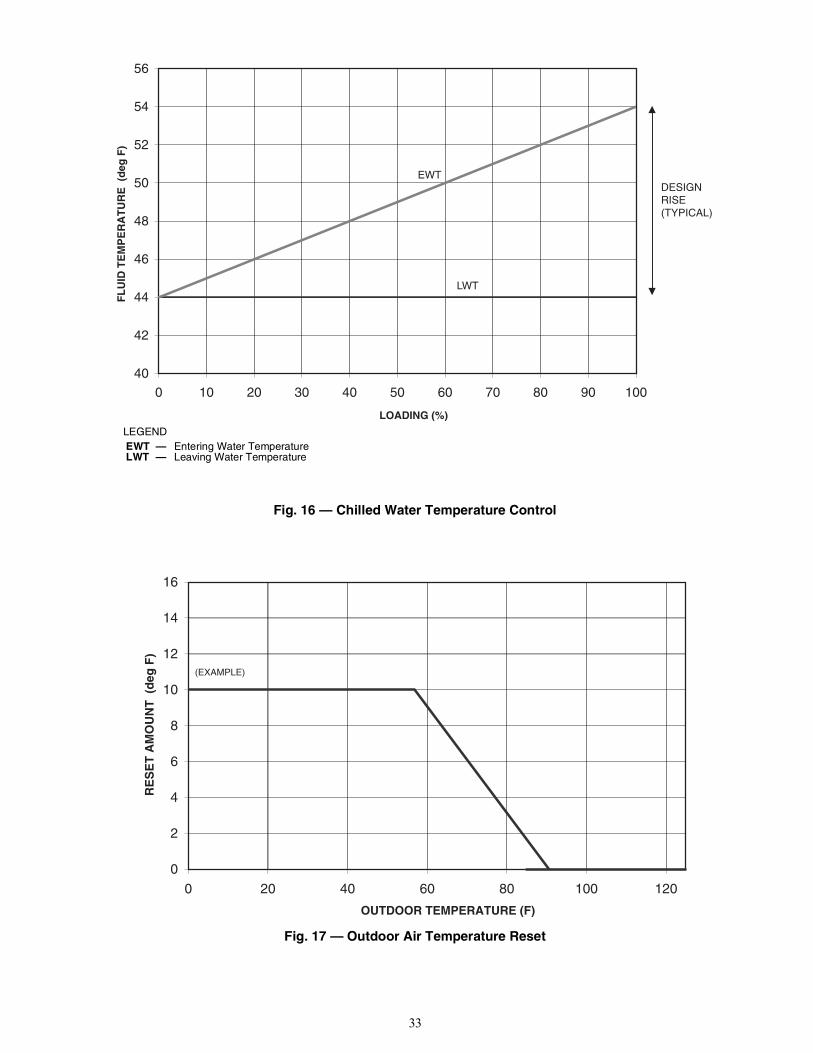
33
Fig. 16 — Chilled Water Temperature Control
Fig. 17 — Outdoor Air Temperature Reset
04
24
44
64
84
05
25
45
65
0010908070605040302010
LOADING (%)
FL
UID
TE
MP
ER
AT
UR
E (
deg
F)
DESIGNRISE(TYPICAL)
LWT
EWT
LEGENDEWT — Entering Water TemperatureLWT — Leaving Water Temperature
0
2
4
6
8
01
21
41
61
021001080604020
OUTDOOR TEMPERATURE (F)
RE
SE
T A
MO
UN
T (
deg
F)
(EXAMPLE)

34
Table 29 — Water Temperature Difference Reset Configuration
NOTE: Bold values indicate sub-mode level.
MODE KEYPAD ENTRY DISPLAY ITEM EXPANSION COMMENTCONFIGURATION DISP
UNIT
SERV
OPTN
RSET Reset Cool and Heat Tmp
CRST Cooling Reset Type
0 No Reset
0 No Reset Flashing to indicate Edit mode. May require Password
/ 2 Delta T Temp Use up or down arrows to change value to 2.
2 Accepts the change.
CRST
At mode level
SETPOINTS / Change to Setpoints Mode
COOL Cooling Setpoints
CSP.1 Cooling Setpoint 1
x 4 CRV.2
CRT1 Delta T No Reset Temp Cooler Temperature difference where no temperature reset is required.
0 Value of CRT1
0 Flashing to indicate Edit mode
10.0 Value of No Temperature Reset, 10 from the example.
10.0 Accepts the change.
CRT1
CRT2 Delta T Full Reset Temp Cooler Temperature difference where full temperature reset, DGRC is required.
0 Value of CRT2.
0 Flashing to indicate Edit mode
2.0 Value of full Temperature Reset, 2 from the example.
2.0 Accepts the change.
CRT2
x 4 CRS2
DGRC Degrees Cool Reset Amount of temperature reset required.
0 Value of DGRC
0 Flashing to indicate Edit mode
5.0 Amount of Temperature Reset required, 5 from the example.
5.0 Accepts the change.
DGRC
ENTER
ENTER
ENTER
ENTER
ENTER
ESCAPE
ESCAPE
ENTER
ENTER
ENTER
ENTER
ENTER
ESCAPE
ENTER
ENTER
ENTER
ESCAPE
ENTER
ENTER
ENTER
ESCAPE

35
Table 30 — OAT Reset Configuration
NOTE: Bold values indicate sub-mode level.
MODE KEYPAD ENTRY DISPLAY ITEM EXPANSION COMMENTCONFIGURATION DISP
UNIT
SERV
OPTN
RSET Reset Cool and Heat Tmp
CRST Cooling Reset Type
0 No Reset
0 No Reset Flashing to indicate Edit mode. May require Password
/ 1 Out Air Temp Use up or down arrows to change value to 1.
1 Accepts the change.
CRST
At mode level
SETPOINTS / Change to Setpoints Mode
COOL Cooling Setpoints
CSP.1 Cooling Setpoint 1
x 6 CRT.2
CRO1 OAT No Reset Temp Outdoor Temperature where no temperature reset is required.
0 Value of CRO1
0 Flashing to indicate Edit mode
85.0 Value of No Temperature Reset, 85 from the example.
85.0 Accepts the change.
CRO1
CRO2 OAT Full Reset Temp Outdoor Temperature where full temperature reset, DGRC is required.
0 Value of CRO2.
0 Flashing to indicate Edit mode
55.0 Value of full Temperature Reset, 55 from the example.
55.0 Accepts the change.
CRO2
CRS1
CRS2
DGRC Degrees Cool Reset Amount of temperature reset required.
0 Value of DGRC
0 Flashing to indicate Edit mode
10.0 Amount of Temperature Reset required, 10 from the example.
10.0 Accepts the change.
DGRC
ENTER
ENTER
ENTER
ENTER
ENTER
ESCAPE
ESCAPE
ENTER
ENTER
ENTER
ENTER
ENTER
ESCAPE
ENTER
ENTER
ENTER
ESCAPE
ENTER
ENTER
ENTER
ESCAPE

36
Fig. 18 — Space Temperature Reset
Fig. 19 — 4 to 20 mA Temperature Reset
SPACE TEMPERATURE (F)
DE
GR
EE
S R
ES
ET
(d
egF
)
60 62 64 66 68 70 72 74 76 78 80
0
1
2
3
4
5
6
7(EXAMPLE)
mA SIGNAL
DE
GR
EE
S R
ES
ET
(d
egF
)
20 4 6 8 10 12 14 16 18 20
0
1
2
3
4
5
6

37
Table 31 — Space Temperature Reset Configuration
NOTE: Bold values indicate sub-mode level.
MODE KEYPAD ENTRY DISPLAY ITEM EXPANSION COMMENTCONFIGURATION DISP
UNIT
SERV
OPTN
RSET Reset Cool and Heat Tmp
CRST Cooling Reset Type
0 No Reset
0 No Reset Flashing to indicate Edit mode. May require Password
/ 4 Space Temp Use up or down arrows to change value to 4.
4 Accepts the change.
CRST
At mode level
SETPOINTS / Change to Setpoints Mode
COOL Cooling Setpoints
CSP.1 Cooling Setpoint 1
x 8 CRO2
CRS1 Space T No Reset Temp Space Temperature where no temperature reset is required.
0 Value of CRS1
0 Flashing to indicate Edit mode
72.0 Value of No Temperature Reset, 72 from the example.
72.0 Accepts the change.
CRS1
CRS2 Space T Full Reset Temp Space Temperature where full temperature reset, DGRC is required.
0 Value of CRS2.
0 Flashing to indicate Edit mode
68.0 Value of full Temperature Reset, 68 from the example.
68.0 Accepts the change.
CRS2
DGRC Degrees Cool Reset Amount of temperature reset required.
0 Value of DGRC
0 Flashing to indicate Edit mode
6.0 Amount of Temperature Reset required, 6 from the example.
6.0 Accepts the change.
DGRC
ENTER
ENTER
ENTER
ENTER
ENTER
ESCAPE
ESCAPE
ENTER
ENTER
ENTER
ENTER
ENTER
ESCAPE
ENTER
ENTER
ENTER
ESCAPE
ENTER
ENTER
ENTER
ESCAPE

38
Table 32 — 4 to 20 mA Temperature Reset Configuration
NOTE: Bold values indicate sub-mode level.
MODE KEYPAD ENTRY DISPLAY ITEM EXPANSION COMMENTCONFIGURATION DISP
UNIT
SERV
OPTN
RSET Reset Cool and Heat Tmp
CRST Cooling Reset Type
0 No Reset
0 No Reset Flashing to indicate Edit mode. May require Password
/ 3 4-20 mA Input Use up or down arrows to change value to 3.
3 Accepts the change.
CRST
At mode level
SETPOINTS / Change to Setpoints Mode
COOL Cooling Setpoints
CSP.1 Cooling Setpoint 1
x 2 CSP.3 Cooling Setpoint 3
CRV1 Current No Reset Val Outdoor Temperature where no temperature reset is required.
0 Value of CRV1
0 Flashing to indicate Edit mode
4.0 Value of No Temperature Reset, 4 from the example.
4.0 Accepts the change.
CRV1
CRV2 Current Full Reset Val Current value where full temperature reset, DGRC is required.
0 Value of CRV2.
0 Flashing to indicate Edit mode
20.0 Value of full Temperature Reset, 20 from the example.
20.0 Accepts the change.
CRV2
x 6 CRS2
DGRC Degrees Cool Reset Amount of temperature reset required.
0 Value of DGRC
0 Flashing to indicate Edit mode
5.0 Amount of Temperature Reset required, 5 from the example.
5.0 Accepts the change.
DGRC
ENTER
ENTER
ENTER
ENTER
ENTER
ESCAPE
ESCAPE
ENTER
ENTER
ENTER
ENTER
ENTER
ESCAPE
ENTER
ENTER
ENTER
ESCAPE
ENTER
ENTER
ENTER
ESCAPE

39
Demand LimitDemand limit is a feature that allows the unit capacity to be limit-ed during periods of peak energy usage. Once a Demand Limitcommand has been initiated, the unit capacity will be limited tothe commanded value and will not exceed that value.Three types of demand limiting are available on the 30RB units.The first type is through switch control, which will reduce themaximum capacity by up to three user-configurable percentages.Single-Step Switch Control Demand Limit is standard on all30RB units. To utilize Two and Three-Step Switch Control De-mand Limit, the Energy Management Module is required. Thesecond type of demand limiting is by 4 to 20 mA signal input,which will reduce the maximum capacity linearly from 100% at a4 mA input signal (no reduction) down to the user-configurablelevel at a 20 mA input signal. To utilize 4 to 20 mA Demand Lim-it, the Energy Management Module is required. The third type ofdemand limiting requires a programmable controller (Open orCCN) or UPC, and writes a demand limit directly to the control.Using the scrolling marquee, the Active Demand Limit Val (RunStatusVIEWLIM) will display the current demand limitvalue. A value of 100 will allow the machine to run fully loadedif required. Any value less than 200 will limit the capacity of themachine.To use demand limit, select the type of demand limiting to use.Then configure the demand limit set points based on the typeselected.
SWITCH CONTROLLEDSingle-Step Switch Control Demand Limit is standard on all30RB units. To utilize Two or Three-Step Switch Control DemandLimit, the Energy Management Module is required. The threesteps are achieved through two sets of dry contacts. The contactsfor Demand Limit Switch 1 must be connected to TB5-5, 14. Thecontacts for Demand Limit Switch 2 must be connected to TB6-14,15. See Fig. 20. Several parameters must be configured for switch controlled de-mand limit:• Demand Limit Select (ConfigurationRSETDMDC)• Switch Limit Setpoint 1 (SetpointsMISCDLS1)• Switch Limit Setpoint 2 (SetpointsMISCDLS2), if
Two-Step Switch Control is desired• Switch Limit Setpoint 3 (SetpointsMISCDLS3), if
Three-Step Switch Control is desiredThe position of the Demand Limit Switch contacts shown inFig. 20 will allow for up to three steps of demand limit accordingto Table 33.The actual positions of Demand Limit Switches 1 and 2 seen bythe control can be viewed using the scrolling marquee or Naviga-tor™ display by accessing the items Inputs GEN.1DLS1 orInputsGEN.1DLS2.Follow the example in Table 34 to enable the function and config-ure the step demand limit for 80%, 60%, and 25% capacity limitbased on the switch position described above.
Fig. 20 — Switch Controlled Demand Limit Wiring
Table 33 — Demand Limit Switch Status Response
Table 34 — Switch Controlled Demand Limit (Scrolling Marquee and Navigator™ Display)
SWITCH STATUS DEMAND LIMIT VALUESCROLLING MARQUEE/NAVIGATOR DISPLAY ITEMDemand Limit
Switch 1Demand Limit
Switch 2Open Open None
Closed Open SetpointsMISCDLS1Open Closed SetpointsMISCDLS2
Closed Closed SetpointsMISCDLS3
ITEM EXPANSION PATHSCROLLING MARQUEE NAVIGATOR
DISPLAYValue ExpansionDMDC Demand Limit Select ConfigurationRSET 1 Switch SwitchDLS1 Switch Limit Setpoint 1 SetpointsMISC 80 — 80DLS2 Switch Limit Setpoint 2 SetpointsMISC 60 — 60DLS3 Switch Limit Setpoint 3 SetpointsMISC 25 — 25
MAINBASE
BOARD
J4
EMMBOARD
J4
a30-5710

40
In the example in Table 34, when Demand Limit Switch 1 isclosed and Demand Limit Switch 2 is open, the maximum chillercapacity will be reduced to 80%. When Demand Limit Switch 1 isopen and Demand Limit Switch 2 is closed, the maximum chillercapacity will be reduced to 60%. Similarly, when both DemandLimit Switches are closed, the maximum chiller capacity will bereduced to 25%.EXTERNALLY POWERED (4 TO 20 MA CONTROLLED)The Energy Management Module is required for 4 to 20 mA de-mand limit control. The 4 to 20 mA positive signal is connected toTB6-1 and the negative to TB6-2. Additionally, a field-supplied250-ohm, 1/2-watt resistor must be installed across TB6-1 andTB6-2. See Fig. 21. The Energy Management Module accepts a 0to 5 vdc input. The resistor converts the 4 to 20 mA signal to a 0 to5 vdc input.
Fig. 21 — 4 to 20 mA Demand Limit Input Wiring
The input signal seen by the control can be viewed using thescrolling marquee or Navigator display by accessing the item In-putsGEN.1DMND.To configure demand limit for 4 to 20 mA control, three parame-ters must be configured:• Demand Limit Select
(ConfigurationRSETDMDC)• mA for 100% Demand Limit
(ConfigurationRSETDMMX) • mA for 0% Demand Limit
(ConfigurationRSETDMZE).
In the following example, a 4 mA signal is Demand Limit 100%and a 20 mA Demand Limit signal is 0%. The demand limit is alinear interpolation between the two values entered. See Table 35and Fig. 22. In Fig. 22, if the machine receives a 12 mA signal, themachine controls will limit the capacity to 50%.
Table 35 — 4 to 20 mA Demand Limit (Scrolling Marquee and Navigator Display)
Fig. 22 — Demand Limit Response to mA Signal
EMMBOARD
J7B
CAUTION
Care should be taken when interfacing with other control sys-tems due to possible power supply differences such as a fullwave bridge versus a half wave rectification. Connection ofcontrol devices with different power supplies may result inpermanent damage. ComfortLink controls incorporate powersupplies with half wave rectification. A signal isolation deviceshould be utilized if the signal generator incorporates a fullwave bridge rectifier.
ITEM EXPANSION PATH SCROLLING MARQUEE NAVIGATOR DISPLAYValue Expansion
DMDC Demand Limit Switch ConfigurationRSET 2 4-20 mA Input 4-20 mA InputDMMX mA for 100% Demand Lim ConfigurationRSET 4 — 4DMZE mA for 0% Demand Lim ConfigurationRSET 20 — 20
0
01
02
03
04
05
06
07
08
09
001
02816141210186420
DEMAND LIMIT SIGNAL (mA)
DE
MA
ND
LIM
IT (
%)
22
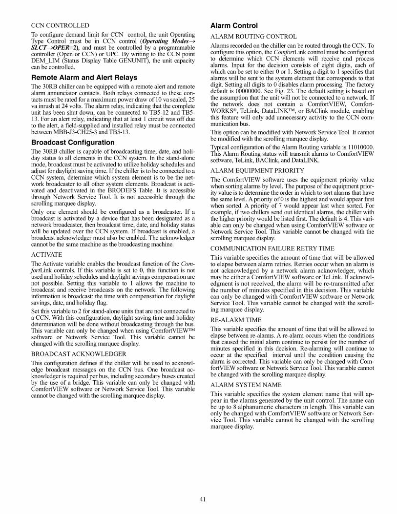
41
CCN CONTROLLEDTo configure demand limit for CCN control, the unit OperatingType Control must be in CCN control (Operating ModesSLCTOPER=2), and must be controlled by a programmablecontroller (Open or CCN) or UPC. By writing to the CCN pointDEM_LIM (Status Display Table GENUNIT), the unit capacitycan be controlled.
Remote Alarm and Alert RelaysThe 30RB chiller can be equipped with a remote alert and remotealarm annunciator contacts. Both relays connected to these con-tacts must be rated for a maximum power draw of 10 va sealed, 25va inrush at 24 volts. The alarm relay, indicating that the completeunit has been shut down, can be connected to TB5-12 and TB5-13. For an alert relay, indicating that at least 1 circuit was off dueto the alert, a field-supplied and installed relay must be connectedbetween MBB-J3-CH25-3 and TB5-13.
Broadcast ConfigurationThe 30RB chiller is capable of broadcasting time, date, and holi-day status to all elements in the CCN system. In the stand-alonemode, broadcast must be activated to utilize holiday schedules andadjust for daylight saving time. If the chiller is to be connected to aCCN system, determine which system element is to be the net-work broadcaster to all other system elements. Broadcast is acti-vated and deactivated in the BRODEFS Table. It is accessiblethrough Network Service Tool. It is not accessible through thescrolling marquee display.Only one element should be configured as a broadcaster. If abroadcast is activated by a device that has been designated as anetwork broadcaster, then broadcast time, date, and holiday statuswill be updated over the CCN system. If broadcast is enabled, abroadcast acknowledger must also be enabled. The acknowledgercannot be the same machine as the broadcasting machine.ACTIVATEThe Activate variable enables the broadcast function of the Com-fortLink controls. If this variable is set to 0, this function is notused and holiday schedules and daylight savings compensation arenot possible. Setting this variable to 1 allows the machine tobroadcast and receive broadcasts on the network. The followinginformation is broadcast: the time with compensation for daylightsavings, date, and holiday flag.Set this variable to 2 for stand-alone units that are not connected toa CCN. With this configuration, daylight saving time and holidaydetermination will be done without broadcasting through the bus.This variable can only be changed when using ComfortVIEW™software or Network Service Tool. This variable cannot bechanged with the scrolling marquee display.BROADCAST ACKNOWLEDGER This configuration defines if the chiller will be used to acknowl-edge broadcast messages on the CCN bus. One broadcast ac-knowledger is required per bus, including secondary buses createdby the use of a bridge. This variable can only be changed withComfortVIEW software or Network Service Tool. This variablecannot be changed with the scrolling marquee display.
Alarm ControlALARM ROUTING CONTROLAlarms recorded on the chiller can be routed through the CCN. Toconfigure this option, the ComfortLink control must be configuredto determine which CCN elements will receive and processalarms. Input for the decision consists of eight digits, each ofwhich can be set to either 0 or 1. Setting a digit to 1 specifies thatalarms will be sent to the system element that corresponds to thatdigit. Setting all digits to 0 disables alarm processing. The factorydefault is 00000000. See Fig. 23. The default setting is based onthe assumption that the unit will not be connected to a network. Ifthe network does not contain a ComfortVIEW, Comfort-WORKS®, TeLink, DataLINK™, or BAClink module, enablingthis feature will only add unnecessary activity to the CCN com-munication bus.This option can be modified with Network Service Tool. It cannotbe modified with the scrolling marquee display.Typical configuration of the Alarm Routing variable is 11010000.This Alarm Routing status will transmit alarms to ComfortVIEWsoftware, TeLink, BAClink, and DataLINK.ALARM EQUIPMENT PRIORITYThe ComfortVIEW software uses the equipment priority valuewhen sorting alarms by level. The purpose of the equipment prior-ity value is to determine the order in which to sort alarms that havethe same level. A priority of 0 is the highest and would appear firstwhen sorted. A priority of 7 would appear last when sorted. Forexample, if two chillers send out identical alarms, the chiller withthe higher priority would be listed first. The default is 4. This vari-able can only be changed when using ComfortVIEW software orNetwork Service Tool. This variable cannot be changed with thescrolling marquee display.COMMUNICATION FAILURE RETRY TIMEThis variable specifies the amount of time that will be allowedto elapse between alarm retries. Retries occur when an alarm isnot acknowledged by a network alarm acknowledger, whichmay be either a ComfortVIEW software or TeLink. If acknowl-edgment is not received, the alarm will be re-transmitted afterthe number of minutes specified in this decision. This variablecan only be changed with ComfortVIEW software or NetworkService Tool. This variable cannot be changed with the scroll-ing marquee display.RE-ALARM TIMEThis variable specifies the amount of time that will be allowed toelapse between re-alarms. A re-alarm occurs when the conditionsthat caused the initial alarm continue to persist for the number ofminutes specified in this decision. Re-alarming will continue tooccur at the specified interval until the condition causing thealarm is corrected. This variable can only be changed with Com-fortVIEW software or Network Service Tool. This variable cannotbe changed with the scrolling marquee display. ALARM SYSTEM NAMEThis variable specifies the system element name that will ap-pear in the alarms generated by the unit control. The name canbe up to 8 alphanumeric characters in length. This variable canonly be changed with ComfortVIEW software or Network Ser-vice Tool. This variable cannot be changed with the scrollingmarquee display.

42
Fig. 23 — Alarm Routing Control
PRE-START-UP
Do not attempt to start the chiller until the following checks havebeen completed.
System Check1. Check auxiliary components, such as the chilled fluid circu-
lating pump, air-handling equipment, or other equipment towhich the chiller supplies liquid are operational. Consultmanufacturer’s instructions. If the unit has field-installedaccessories, be sure all are properly installed and wired cor-rectly. Refer to unit wiring diagrams.
2. Open compressor suction (if equipped) and discharge shutoffvalves.
3. Open liquid line shutoff valves.4. Fill the chiller fluid circuit with clean water (with recom-
mended inhibitor added) or other non-corrosive fluid to becooled. Bleed all air out of high points of system. An air ventpipe plug is included with the cooler. If outdoor temperaturesare expected to be below 32°F (0°C), sufficient inhibited pro-pylene glycol or other suitable corrosion inhibited antifreezeshould be added to the chiller water circuit to prevent possiblefreeze-up.The chilled water loop must be cleaned before the unit isconnected. Units supplied with the accessory hydronicpackage include a run in screen. If the run-in screen is leftin the suction guide/strainer, it is recommended that theService Maintenance be set to alert the operator within 24hours of start-up to be sure that the run-in screen in thesuction guide/strainer is removed. To set the time for theparameter, go to Time ClockMCFGW.FIL. Valuesfor this item are counted as days. Refer to the hydronicpump package literature if unit is equipped with theoptional hydronic pump package.
5. Check tightness of all electrical connections.6. Oil should be visible in the compressor sight glass. An
acceptable oil level in the compressor is from 3/4 to 7/8 fullsight glass. Adjust the oil level as required. No oil should be
removed unless the crankcase heater has been energized for atleast 24 hours. See Oil Charge section for Carrier-approvedoils.
7. Electrical power source must agree with unit nameplate.8. Crankcase heaters must be firmly seated under compressor,
and must be energized for 24 hours prior to start-up.9. Verify power supply phase sequence. Check reverse rotation
board. If lower (red) LED is blinking, the phase sequence isincorrect. Reverse two of the power wires at the main termi-nal block. Units with dual power point connection utilize tworeverse rotation boards. Check both for proper phasesequence.
10. Check compressors and compressor mounting sled. Com-pressor shipping braces and shipping bolts must be removed.
START-UP
Actual Start-UpActual start-up should be done only under supervision of a quali-fied refrigeration technician.1. Be sure all shut off valves are open. Units are shipped from
factory with suction valves (if equipped) open. Discharge andliquid line shut off valves are closed.
2. Using the scrolling marquee display, set leaving-fluid setpoint (SetpointsCOOLCSP.1). No cooling range adjust-ment is necessary.
3. If optional control functions or accessories are being used, theunit must be properly configured. Refer to ConfigurationOptions section for details.
4. Start chilled fluid pump, if unit is not configured for pumpcontrol, (ConfigurationOPTNPUMP= 0).
5. Complete the Start-Up Checklist to verify all components areoperating properly.
6. Turn ENABLE/OFF/REMOTE CONTACT switch toENABLE position.
7. Allow unit to operate and confirm that everything is function-ing properly. Check to see that leaving fluid temperatureagrees with leaving set point Control Point (Run StatusVIEWCTPT).
DESCRIPTION STATUS POINT Alarm Routing 0 0 0 0 0 0 0 0 ALRM_CNT
ComfortVIEW™ or ComfortWORKS™
TeLink
Unused
BACLink or DataLINK™
Unused
Important: Complete the Start-Up Checklist for 30RB Liq-uid Chillers at the end of this publication.The checklist assures proper start-up of a unit, and providesa record of unit condition, application requirements, systeminformation, and operation at initial start-up.
CAUTION
Do not manually operate contactors. Serious damage to themachine may result.

43
Operating LimitationsTEMPERATURESUnit operating temperature limits are listed in Table 36.
Table 36 — Temperature Limits for Standard Units
LEGEND
*For sustained operation, EWT should not exceed 85°F (29.4°C).†Unit requires brine modification for operation below this temperature.
Low Ambient OperationIf unit operating temperatures below 32°F (0°C) are expected, re-fer to separate unit installation instructions for low ambient tem-perature operation using accessory low ambient temperature headpressure control, if not equipped. Contact a Carrier representativefor details.NOTE: Wind baffles and brackets must be field-fabricated and in-stalled for all units using accessory low ambient head pressurecontrol to ensure proper cooling cycle operation at low-ambienttemperatures. See the 30RB Installation Instructions or the lowambient temperature head pressure control accessory installationinstructions for more information.
VOLTAGEMain Power SupplyMinimum and maximum acceptable supply voltages are listed inthe Installation Instructions.Unbalanced 3-Phase Supply VoltageNever operate a motor where a phase imbalance between phases isgreater than 2%.The maximum voltage deviation is the largest difference between avoltage measurement across 2 legs and the average across all 3 legs. Example: Supply voltage is 240-3-60.
Example: Supply voltage is 230-3-60
Determine maximum deviation from average voltage.(AB) 243 – 239 = 4 v(BC) 239 – 236 = 3 v(AC) 239 – 238 = 1 vMaximum deviation is 4 v.Determine percent of voltage imbalance.
This amount of phase imbalance is satisfactory as it is below the maxi-mum allowable 2%.
MINIMUM FLUID LOOP VOLUMETo obtain proper temperature control, loop fluid volume must beat least 3 gallons per ton (3.25 L per kW) of chiller nominal capac-ity for air conditioning and at least 6 gallons per ton (6.5 L perkW) for process applications or systems that must operate at lowambient temperatures (below 32°F [0°C]). Refer to application in-formation in Product Data literature for details.FLOW RATE REQUIREMENTS Standard chillers should be applied with nominal flow rates withinthose listed in the Minimum and Maximum Cooler Flow Rates ta-ble. Higher or lower flow rates are permissible to obtain lower orhigher temperature rises. Minimum flow rates must be exceededto assure turbulent flow and proper heat transfer in the cooler. SeeTable 37.
Consult application data section in the Product Data literature andjob design requirements to determine flow rate requirements for aparticular installation.
TEMPERATURE F CMaximum Ambient Temperature 125 52Minimum Ambient Temperature 32 0Maximum Cooler EWT* 95 35Maximum Cooler LWT 60 15Minimum Cooler LWT† 40 4.4
EWT — Entering Fluid (Water) TemperatureLWT — Leaving Fluid (Water) Temperature
CAUTION
Brine duty application (below 40°F [4.4°C] leaving chilledwater temperature) for chiller normally requires factorymodification. Contact your Carrier representative fordetails regarding specific applications. Operation below40°F (4.4°C) leaving chilled water temperature withoutmodification can result in compressor failure.
% Voltage Imbalance = 100 x
max voltage deviation from average voltageaverage voltage
AB = 243 vBC = 236 vAC = 238 v
Average Voltage =(243 + 236 + 238)
=717
= 2393 3
% Voltage Imbalance = 100x4
= 1.7%239
IMPORTANT: If the supply voltage phase imbalance is more than 2%,contact your local electric utility company immediately. Do not operateuntil imbalance condition is corrected.
CAUTIONOperation below minimum flow rate could subject tubes to frostpinching in the tube sheet, resulting in failure of the cooler.
A B C
MOTOR

44
Table 37 — Minimum and Maximum Cooler Flow RatesSIZES 060-300
SIZES 315-390
OPERATION
Sequence of OperationWith a command to start the chiller, the cooler pump will start. Af-ter verifying water flow, the control will monitor the entering andleaving water temperature. At any time that a compressor is notoperating, its crankcase heater is active. If the need for mechanicalcooling is determined, the control decides which circuit and com-pressor to start. The compressor will deenergize the crankcaseheater as it starts. Compressors will be staged with minimum loadcontrol (if equipped and configured) to maintain LWT set point.Shutdown of each circuit under normal conditions occurs in incre-ments, starting with the minimum load control (if equipped) andfinishing with the last running compressor. Once minimum loadcontrol is disabled, one compressor is shut down. Eight secondslater the next compressor will shut down. The process will contin-ue until all of the compressors are shut down. The EXV will closecompletely, 1 minute after the last compressor has shut down.There are several abnormal conditions that, if detected, will shutdown the circuit immediately. In this case, minimum load controland all compressors are turned off without an 8-second interval be-tween them. The cooler pump will remain ON for 20 seconds afterthe last compressor has been turned OFF.
Dual Chiller Sequence of Operation With a command to start the chiller, the master chiller deter-mines which chiller will become the lead chiller based on Con-figurationRSETLLBL and ConfigurationRSETLLBD. The lead chiller is always started first and the lagchiller is held at zero percent capacity by the master chillerforcing the lag demand limit value to 0%. The lead chiller’swater pump will be started. The lag chiller’s water pump shall
be maintained off if ConfigurationRSETLAGP=0. Theinternal algorithm of lead chiller will control capacity of thelead chiller.If Lead Pulldown Time (ConfigurationRSETLPUL) hasbeen configured, the lead chiller will continue to operate alonefor that specified time. After the Lead Pulldown Time timerhas elapsed, if the lead chiller is fully loaded and either allavailable compression is on or at the master demand limit val-ue, then the lag start timer (ConfigurationRSETLLDY) isinitiated. When the pulldown timer and lag start timer haveelapsed and the Combined Leaving Chilled Water Temperature ismore than 3°F (1.7°C) above the set point, then the lag chiller isstarted.If the lag chiller’s water pump was not started when the ma-chines went into occupied mode, then the lag chiller water pumpwill be started. The lag chiller will start when the master chillerforcing the lag chiller demand limit value (LAG_LIM) to themaster’s demand limit value. If lead/lag capacity balance is se-lected, once the lag chiller has started, the master chiller will tryto keep the difference in capacity between lead and lag to lessthan 20%. The master chiller will then be responsible for waterloop capacity calculation, and will determine which chiller, thelead or lag, will increase or decrease capacity. When the load re-duces, the lag chiller will unload first. To accomplish this, thelead chiller set point is decreased by 4°F (–2.2°C) until the lagchiller unloads.To configure the two chillers for dual chiller operation, the masterchiller must have the Control Method variable (OperatingModeSLCTOPER) set to meet the job requirements. Theslave chiller must be set to Control Method variable (OperatingModeSLCTOPER) = 2 (CCN Control) and the remote-off-enable switch must be in the enable position. The master chiller
30RB SIZE
MINIMUM COOLER
FLOW RATE (gpm)
MAXIMUM FLOW RATE
(gpm)
MINIMUM LOOP
VOLUME (gal.)
MINIMUM COOLER FLOW RATE
(l/s)
MAXIMUM COOLER
FLOW RATE (l/s)
MINIMUM LOOP
VOLUME (liters)
060 72 288 180 5 18 681070 84 336 210 5 21 795080 96 384 240 6 24 908090 108 432 270 7 27 1022100 120 480 300 8 30 1136110 132 528 330 8 33 1249120 144 576 360 9 36 1363130 156 624 390 10 39 1476150 180 720 450 11 45 1703160 192 768 480 12 48 1817170 204 816 510 13 51 1931190 228 912 570 14 58 2158210 252 950 630 16 60 2385225 270 950 675 17 60 2555250 300 950 750 19 60 2839275 330 950 825 21 60 3123300 360 950 900 23 60 3407
30RB SIZE
MINIMUM COOLER FLOW RATE
(gpm)
MAXIMUM COOLER FLOW RATE
(gpm)
MIN LOOP
VOLUME (gal.)
MINIMUM COOLER FLOW RATE
(l/s)
MAXIMUM COOLER FLOW RATE
(l/s)
MIN LOOP
VOLUME (liters)Module A Module B Module A Module B Module A Module B Module A Module B
315 192 192 768 768 945 12 12 48 48 3577330 204 192 816 768 990 12 12 51 48 3748345 204 204 816 816 1035 13 13 51 51 3918360 228 204 912 816 1080 14 13 58 51 4088390 228 228 912 912 1170 14 14 58 58 4429

45
and the slave chiller CCN addresses (ConfigurationOPTNCCNA) must be configured. The master and slavechillers can be addressed from 1 to 239. Each device connected tothe network must have its own unique address.Both chillers must have the same CCN Bus Number (Configura-tionOPTNCCNB). Lead/Lag Chiller Enable must be set forboth chillers by configuring Master/Slave Select (Configura-tionRSETMSSL) to 1 (Master) for the master chiller. Theslave chiller Master/Slave Select must be set to 2 (Slave). Themaster chiller can be configured to use Lead/Lag Balance (Con-figurationRSETLLBL) to rotate the lead and lag chillers af-ter a configured number of hours of operation. The Lag Start De-lay (ConfigurationRSETLLBD) can be configured. Thisprevents the Lag chiller from starting until the lead chiller is fullyloaded and the delay has elapsed.
Operating ModesMODE 1 (OPERATING MODEMODEMD01):STARTUP DELAY IN EFFECTCriteria for ModeTested when the unit is started. This mode is active when the Min-utes Off Time (ConfigurationOPTNDELY) timer is active.Action TakenThe unit will not start until the timer has expired.TerminationThe mode will terminate when the timer expires.Possible CausesThis mode is in effect only due to the Minutes Off Time timer.MODE 2 (OPERATING MODEMODEMD02):SECOND SETPOINT IN USECriteria for ModeTested when the unit is ON. This mode is active when CoolingSetpoint 2 (SetpointsCOOL CSP.2) or Ice Setpoint (Set-pointsCOOLCSP.3) is in use. While in this mode, the ActiveSetpoint (Run StatusVIEWSETP) will show the CSP.2 orCSP.3 value.Action TakenThe unit will operate to the Cooling Setpoint 2 (CSP.2) or Ice Set-point (CSP.3).TerminationThis mode will terminate when the Cooling Setpoint 2 (CSP.2) orIce Setpoint (CSP.3) is no longer in use.Possible CausesThis mode is in effect only due to programming options.MODE 3 (OPERATING MODEMODEMD03): RESETIN EFFECTCriteria for ModeTested when the unit is ON. This mode is active when Tempera-ture Reset (ConfigurationRSETCRST) is enabled either byCRST=1 (Outside Air Temperature), CRST=2 (Return Water),CRST=3 (4-20 mA Input), or CRST=4 (Space Temperature) andis active.Action TakenThe Active Setpoint (Run StatusVIEW SETP) will be modi-fied according to the programmed information and will be dis-played as the Control Point (Run StatusVIEWCTPT).TerminationThis mode will terminate when the Temperature Reset is not mod-ifying the active leaving water set point, so SETP is the same asCTPT.Possible CausesThis mode is in effect only due to programming options.
MODE 4 (OPERATING MODEMODEMD04):DEMAND LIMIT ACTIVECriteria for ModeTested when the unit is ON. This mode is active when DemandLimit (ConfigurationRSET DMDC) is enabled either byDMDC=1 (Switch), DMDC=2 (4-20 mA Input) or the NightTime Low Sound Capacity Limit (ConfigurationOPTNLS.LT).Action TakenThe Active Demand Limit Value (Run StatusVIEWLIM)will display the current demand limit according to the pro-grammed information and the unit’s capacity will be reduced tothe amount shown or lower.TerminationThis mode will terminate when the Demand Limit command hasbeen removed.Possible CausesThis mode is in effect when capacity is being limited by the de-mand limit function.MODE 5 (OPERATING MODEMODEMD05): RAMPLOADING ACTIVECriteria for ModeTested when the unit is ON. This mode is active when RampLoading (ConfigurationOPTNRL.S) is enabled and the fol-lowing conditions are met:1. The leaving water temperature is more than 4°F (2.2°C) from
the Control Point (Run StatusVIEWCTPT), and2. The rate of change of the leaving water temperature is greater
than the Cool Ramp Loading (Set PointsCOOLCRMP).Action TakenThe control will limit the capacity step increase until one of thetwo conditions in Mode 5 is no longer true.TerminationThis mode will terminate once both conditions in Mode 5 are nolonger true.Possible CausesThis mode is in effect only when capacity is being limited by theramp loading function.MODE 6 (OPERATING MODEMODEMD06):COOLER HEATER ACTIVECriteria for ModeTested when unit is ON or OFF. This mode is active when thecooler heater is energized, if the Outdoor Air Temperature (Tem-peratureUNITOAT) is less than the calculated value (FreezeSetpoint + Cooler Heater Delta T Setpoint [Configura-tionSERVHTR] default – 2°F [1.1°C]), and either the Leav-ing Water Temperature (TemperatureUNITLWT) or the En-tering Water Temperature (TemperatureUNITEWT) are lessthan or equal to the Freeze Setpoint + Cooler Heater Delta T Set-point (HTR).The Freeze Setpoint is 34°F (1.1°C) for fresh water systems (Con-figurationSERVFLUD=1). The Freeze Setpoint is the BrineFreeze Setpoint (ConfigurationSERVLOSP) for MediumTemperature Brine systems (ConfigurationSERVFLUD=2).Action TakenThe cooler heater will be energized.TerminationThe cooler heater will be deenergized when both the Entering Wa-ter Temperature (EWT) and Leaving Water Temperature (LWT)are above the Freeze Setpoint + Cooler Heater Delta T Setpoint(HTR).

46
Possible CausesThis mode will be enabled for freeze protection. If the tempera-tures are not as described above, check the accuracy of the outsideair, entering and leaving water thermistors.MODE 7 (OPERATING MODEMODEMD07): WATERPUMP ROTATIONCriteria for ModeTested when the unit is ON or OFF. This mode is active when theCooler Pump Sequence (ConfigurationOPTNPUMP) =2 (2Pumps Automatic Changeover) and the Pump Rotation DeltaTimer (ConfigurationOPTN ROT.P) has expired.Action TakenThe control will switch the operation of the pumps. The leadpump will be operating normally. The lag pump will be started,becoming the lead, and then the original lead pump will be shutdown.TerminationThis mode will terminate when the pump operation has been com-pleted.Possible CausesThis mode is in effect only due to programming options.MODE 8 (OPERATING MODEMODEMD08): PUMPPERIODIC STARTCriteria for ModeThis mode is active when the cooler pump is started for the Peri-odic Pump Start configuration (ConfigurationOPTNPM.PS=YES).Action TakenIf the pump has not run that day, a pump will be started and willrun for 2 seconds at 2:00 PM. If the machine is equipped with dualpumps, Pump no. 1 will run on even days (such as day 2, 4, 6 ofthe month). Pump no. 2 will run on odd days (such as day 1, 3, 5of the month).TerminationThis mode will terminate when the pump shuts down.Possible CausesThis mode is in effect only due to programming options.MODE 9 (OPERATING MODEMODEMD09): NIGHTLOW NOISE ACTIVECriteria for ModeThis mode is active when the Night Time Low Noise Option hasbeen configured and the time is within the configured time. Pro-gramming a Night Low Noise Start Time (Configura-tionOPTNLS.ST) and a Night Low Noise End Time (Con-figurationOPTNLS.ND) configures the option.Action TakenThe control will raise the head pressure set point to reduce thenumber of condenser fans on, thereby reducing the sound of themachine. Additionally, if the Night Time Low Sound CapacityLimit (ConfigurationOPTN LS.LT) has been configured,the units capacity will be limited to the programmed level.TerminationThis mode will terminate once the Night Low Noise End Time(LS.ND) has been reached.Possible CausesThis mode is in effect only due to programming options.
MODE 10 (OPERATING MODEMODEMD10): SYS-TEM MANAGER ACTIVECriteria for ModeTested when the unit is ON or OFF. This mode is active if a Sys-tem Manager such as Building Supervisor, Chillervisor SystemManager, or another CCN device is controlling the machine.Action TakenThe machine will respond to the specific command received fromthe System Manager.TerminationThe mode will be terminated if the System Manager control is re-leased.Possible Causes This mode is in effect only due to programming options.MODE 11 (OPERATING MODEMODEMD11): MASTSLAVE CTRL ACTIVECriteria for ModeTested if the machine is ON. This mode is active if the MasterSlave Control has been enabled. and 2 machines are programmed,one as the master (Configuration RSETMSSL=1 [Master])and the other as a slave (ConfigurationRSETMSSL=2[Slave]).Action TakenBoth the master and slave machine will respond to the capacitycontrol commands issued by the master controller. This may in-clude control point changes and demand limit commands.TerminationThis mode will terminate when the Master Slave Control has beendisabled.Possible CausesThis mode is in effect only due to programming options.MODE 12 (OPERATING MODEMODEMD12): AUTOCHANGEOVER ACTIVECriteria for ModeThis mode is not supported for Cooling Only units.Action TakenNone.TerminationNone.Possible CausesThis mode is in effect only due to programming options.MODE 13 (OPERATING MODEMODEMD13): FREECOOLING ACTIVECriteria for ModeThis mode is not supported for Cooling Only units.Action TakenNone.TerminationNone.Possible CausesThis mode is in effect only due to programming options.MODE 14 (OPERATING MODEMODEMD14):RECLAIM ACTIVECriteria for ModeThis mode is not supported for Cooling Only units.Action TakenNone.

47
TerminationNone.Possible CausesThis mode is in effect only due to programming options.MODE 15 (OPERATING MODEMODEMD15): ELEC-TRIC HEAT ACTIVECriteria for ModeThis mode is not supported for Cooling Only units.Action TakenNone.TerminationNone.Possible CausesThis mode is in effect only due to programming options.MODE 16 (OPERATING MODEMODEMD16): HEAT-ING LOW EWT LOCKOUTCriteria for ModeThis mode is not supported for Cooling Only units.Action TakenNone.TerminationNone.Possible CausesThis mode is in effect only due to programming options.MODE 17 (OPERATING MODEMODEMD17):BOILER ACTIVECriteria for ModeThis mode is not supported for Cooling Only units.Action TakenNone.TerminationNone.Possible CausesThis mode is in effect only due to programming options.MODE 18 (OPERATING MODEMODEMD18): ICEMODE IN EFFECTCriteria for ModeTested when the unit is ON. This mode is active when Ice Setpoint(SetpointsCOOLCSP.3) is in use. While in this mode, theActive Setpoint (Run Status VIEWSETP) will show theCSP.3 value.Action TakenThe unit will operate to the Ice Setpoint (CSP.3).TerminationThis mode will terminate when the Ice Setpoint (CSP.3) is no lon-ger in use.Possible CausesThis mode is in effect only due to programming options.MODE 19 OPERATING MODEMODEMD19):DEFROST ACTIVE ON CIR A
MODE 20 (OPERATING MODEMODEMD20):DEFROST ACTIVE ON CIR BCriteria for ModeThis mode is not supported for Cooling Only units.
Action TakenNone.TerminationNone.Possible CausesThis mode is in effect only due to programming options.MODE 21 (OPERATING MODEMODEMD21): LOWSUCTION CIRCUIT A
MODE 22 (OPERATING MODEMODEMD22): LOWSUCTION CIRCUIT B
MODE 23 (OPERATING MODEMODEMD23): LOWSUCTION CIRCUIT CCriteria for ModeThe criteria are tested when the circuit is ON. The appropriate cir-cuit mode will be active if one of the following conditions is true:1. If the circuit’s Saturated Suction Temperature (SST) is more
than 6°F (3.3°C) less than the freeze point and both the coolerapproach (Leaving Water Temperature—SST) and superheat(Suction Gas Temperature—SST) are greater than 15°F(8.3°C).
2. If there is more than one compressor ON in the circuit and thecircuit’s SST is greater than 18°F (10.0°C) below the freezepoint for more than 90 seconds.
3. If there is more than one compressor ON in the circuit and thecircuit’s SST is greater than –4°F (–20.0°C) and the SST 30seconds ago was 18°F (10.0°C) below the freeze point.
4. If the circuit’s saturated suction temperature is greater than6°F (3.3°C) below the freeze point for more than 3 minutes.
For a fresh water system (ConfigurationSERVFLUD =1),the freeze point is 34°F (1.1°C). For medium temperature brinesystems, (ConfigurationSERVFLUD=2), the freeze point isBrine Freeze Set Point (ConfigurationSERVLOSP).Action TakenFor criterion 1, no additional stages will be added. For criteria 2, 3and 4, one stage of capacity will be removed.TerminationThe mode will terminate when the circuit’s Saturated SuctionTemperature is greater than the freeze point minus 6°F (3.3°C) orthe circuit has alarmed.Possible CausesIf this condition is encountered, see Possible Causes for AlarmsP.05, P.06, and P.07 on page 72.MODE 24 (OPERATING MODEMODEMD24): HIGHDGT CIRCUIT A
MODE 25 (OPERATING MODEMODEMD25): HIGHDGT CIRCUIT B
MODE 26 (OPERATING MODEMODEMD26): HIGHDGT CIRCUIT CCriteria for ModeThis mode is tested for when any circuit is running. The circuitsaturated condensing and suction temperatures are monitored toensure that the compressors always operate withing their allowed“map.” Operation at conditions at or outside the “map” boundarieswill cause this mode to be in effect. Operation at extremely lowsuction pressures and high condensing temperatures will cause themode to be generated.Action TakenThe circuit will not be allowed to increase capacity and may be au-tomatically unloaded or stopped.

48
TerminationThis mode will terminate when or if the circuit refrigerant condi-tions return to within the compressor “map.”Possible CausesThis mode could be in effect due to a low fluid flow rate, over-charge of oil in a circuit, dirty condenser coils, refrigerant over-charge, or excessive brine concentration.MODE 27 (OPERATING MODEMODEMD27): HIGHPRES OVERRIDE CIR A
MODE 28 (OPERATING MODEMODEMD28): HIGHPRES OVERRIDE CIR B
MODE 29 (OPERATING MODEMODEMD29): HIGHPRES OVERRIDE CIR CCriteria for ModeTested when the circuit is ON. The appropriate circuit mode willbe active if the discharge pressure for the circuit, Discharge Pres-sure Circuit A (Pressure PRC.ADP.A), Discharge PressureCircuit B (PressurePRC.BDP.B), or Discharge PressureCircuit C (PressurePRC.CDP.C) is greater than the HighPressure Threshold (ConfigurationSERVHP.TH).Action TakenThe capacity of the affected circuit will be reduced. If the unit isequipped with Minimum Load Control and has been configuredfor High Ambient (Configuration UNITHGBP=3), the min-imum load control valve will be energized. Two minutes follow-ing the capacity reduction, the circuit’s saturated condensing tem-perature (SCT) is calculated and stored. The affected circuit willnot be allowed to add capacity for at least 5 minutes following thecapacity reduction. If after 5 minutes, the circuit’s saturated con-densing temperature is less than SCT – 3°F (1.7°C), if required,another stage of capacity will be added.If additional steps of capacity are required, the control will lookfor other circuits to add capacity.TerminationThis mode will terminate once the circuit’s saturated condensingtemperature is less than SCT –3°F (1.7°C).Possible CausesIf this condition is encountered, see Possible Causes for AlarmA1.03. on page 68.MODE 30 (OPERATING MODEMODEMD30): LOWSUPERHEAT CIRCUIT A
MODE 31 (OPERATING MODEMODEMD31): LOWSUPERHEAT CIRCUIT B
MODE 32 (OPERATING MODEMODEMD32): LOWSUPERHEAT CIRCUIT CCriteria for ModeTested when the circuit is ON with at least 1 compressor ON. Theappropriate circuit mode will be active is the circuit’s superheat isless than 5°F (2.8°C) or greater than 45°F (25°C).Action Taken No additional stages of circuit capacity will be added until the cir-cuit’s superheat is greater than 5°F (2.8°C) and less than 45°F(25°C).The control will look for other circuits to add capacity if additionalsteps of capacity are required.TerminationThis mode will terminate once the affected circuit’s superheat isgreater than 5°F (2.8°C) and less than 45°F (25°C).
Possible CausesIf this condition is encountered, see Possible Causes for AlarmsP.08, P.09, P.10, P.11, P.12 and P.13 on page 73.
Optional Heat Reclaim ModuleThe heat reclaim option adds a water-cooled condenser in parallelwith the standard air-cooled condenser for the purpose of simulta-neously producing tempered hot water while satisfying the chilledwater requirement.For chillers with the heat reclaim option, Configuration→UNIT→RECL should be set to YES.This option requires installation of an additional board (EMM-HR). This board allows control of the components shown in Table 11.Table 38 lists EMM-HR outputs for the solenoid valves. Itemnumbers in Table 38 refer to Fig. 24 of this document.For more control details, refer to the unit low voltage control sche-matic (Fig. 25).The heat reclaim mode can be selected by either the Heat Recov-ery Enable Switch or by CCN control.SWITCH CONTROLLEDTo configure Heat Reclaim for SWITCH control, the unit Operat-ing Type Control can be configured to 0, 1 or 2 (OperatingModes→SLCT→OPER). The Reclaim Select configuration mustbe set to “Switch Control” (Operating Modes→SLCT→RL.SE=2). Switch input connection should be field wired to ter-minals 14 and 15 on TB7, cooling mode (open) or heat reclaimmode (closed). Switch status can be accessed through In-put→GEN.I→RECL.CCN CONTROLTo configure Heat Reclaim for CCN control, the unit OperatingType Control must be set to CCN control (Operatingmode→SLCT→OPER=2). The Reclaim Select configurationmust be set to “Yes” (Operating Modes→SLCT→RL.SE=1).Heat reclaim mode is selected by forcing CCN point RECL_SEL(Status Display→GENUNIT→RECL_SEL) to “NO” for coolingmode or “YES” for Heat Reclaim mode.The heat reclaim function is active when the heat reclaim enteringwater temperature is lower than the heat reclaim set point (Set-points→MISC→RSP), default 122°F (50°C), minus half or quar-ter of the heat reclaim deadband, depending on the number of re-frigerant circuits in reclaim mode (Setpoints→MISC→RDB).The default heat reclaim deadband is 9°F (5.0°C) and the recom-mended deadband range is 5 to 18°F (2.8 to 10°C).The difference between the reclaim entering water temperatureand reclaim set point will determine if one or two circuits are re-quired to provide heat reclaim capacity. See Table 39 for details.Heat Reclaim Active status is indicated by MODE_14=ON (Op-erating Modes→MODE→MD14) from the scrolling marqueedisplay or Mode_14=1 accessed through CCN.The following is the changeover procedure from cooling mode toheat reclaim mode. 1. Verify that the circuit has run for more than 2 minutes in
cooling. 2. Start the reclaim pump. 3. Verify the reclaim condenser flow switch is closed. If this
remains open after one minute of condenser pump operation,the circuit remains in cooling mode and P.15 alarm will beactivated.
Once water flow is established the following conditions must betrue:• saturated condensing temperature is greater than saturated
suction temperature plus 18°F (10°C)

49
• if reclaim water entering requires the circuit to go to a heatreclaim session and the number of air cooled to reclaimchangeovers is not greater than 4 per hour
• the last changeover occurred more than 7 minutes agoWhen all of these conditions are true, the heat reclaim pumpdownsequence is activated. During heat reclaim pumpdown, the controlwill open the entering heat reclaim condenser solenoid valve andclose the entering air-cooled condenser solenoid valves 3 secondslater. After one minute or when the subcooling value is above13.2°F (–10.4°C), the heat reclaim operation is effective.During the heat reclaim operation, if the sub-cooling value is lessthan 13.2°F (–10.4°C) leaving air-cooled condenser solenoidsmay activate for 3 seconds every 20 seconds to recover morecharge. If sub-cooling is greater than 16° F (9.0° C) the enteringair cooled condenser solenoids may activate for 3 seconds every20 seconds to transfer charge back into the air-cooled condenser toprevent excessive condensing temperature. The leaving heat re-claim condenser solenoid should remain closed.Once the heat reclaim set point (RSP) is satisfied, the system willtransition back to normal air-cooled mode. The air-cooled pump-down sequence is activated. During air-cooled pumpdown, thecontrol will open the entering air-cooled condenser solenoids andclose the entering heat reclaim condenser valves 3 seconds later.
During the air-cooled operation, leaving heat reclaim condensersolenoids may activate for 3 seconds every 20 seconds to recovermore charge into air-cooled operation, based on the system sub-cooling level. Leaving air-cooled condenser solenoids should re-main closed.Heat reclaim entering water temperature (HEWT), leaving watertemperature (HLWT), heat reclaim pump hours (HR.CD), refrig-erant sub-cooling (HRS.x) can be accessed from the scrollingmarquee display through the following paths:
Temperatures→UNIT→HEWTTemperature→UNIT→HLWTRun Status→RUN→HR.CDTemperatures→Cir.A→HRS.ATemperatures→Cir.B→HRS.B
To view circuit status through CCN, two points are available: Re-claim Status Circuit A and Reclaim Status Circuit B. Each willshow a single-digit number as defined in Table 40.RECLAIM CONDENSER WATER VALVE OUTPUTThis output (0 to 10 vdc) controls the heat reclaim condenser 3-way water valve position through a variable speed device. A 10vdc signal corresponds to 100% open.
Table 38 — Heat Reclaim Circuits
Table 39 — Heat Reclaim Staging
OUTPUT ITEM NO. DESCRIPTION CONNECTION RELAY SOLENOIDTYPE
OPERATIONCOOLING RECLAIM
HR1.A 4 Ckt. A Ent A/C Cond. Sol. EMM-J3-CH24 ECA-A N/O OPEN CLOSEDHR2.A 6 Ckt. A Lvg A/C Cond. Sol. EMM-J2-CH18 LCA-A N/C CLOSED CYCLINGHR3.A 2 Ckt. A Ent W/C Cond. Sol. EMM-J2-CH20 ECW-A N/C CLOSED OPENHR4.A 9 Ckt. A Lvg W/C Cond. Sol. EMM-J2-CH22 LCW-A N/C CYCLING CLOSEDHR1.B 5 Ckt. B Ent A/C Cond. Sol. EMM-J3-CH25 ECA-B N/O OPEN CLOSEDHR2.B 7 Ckt. B Lvg A/C Cond. Sol. EMM-J2-CH19 LCA-B N/C CLOSED CYCLINGHR3.B 3 Ckt. B Ent W/C Cond. Sol. EMM-J2-CH21 ECW-B N/C CLOSED OPENHR4.B 10 Ckt. B Lvg W/C Cond. Sol. EMM-J2-CH23 LCW-B N/C CYCLING CLOSED
HEAT RECLAIM ENTERING WATER TEMPERATURE RECLAIM SELECT NUMBER OF CIRCUITS IN RECLAIM
NUMBER OF CIRCUITS IN RECLAIM STATUS CHANGE
– No 0 - 2 hr_ew < rsp - hr_deadb/2 Yes – + 2
rsp - hr_deadb/2 < hr_ewt < rsp - hr_deadb/4 Yes 0 + 1rsp - hr_deadb/2 < hr_ewt < rsp - hr_deadb/4 Yes 1 Unchangedrsp - hr_deadb/4 < hr_ewt < rsp + hr_deadb/4 Yes – Unchangedrsp + hr_deadb/4 < hr_ewt < rsp + hr_deadb/2 Yes 1 Unchangedrsp + hr_deadb/4 < hr_ewt < rsp + hr_deadb/2 Yes 2 - 1
hr_ewt > rsp + hr_deadb/2 Yes – - 2

50
Table 40 — CCN Table Reclaim Status Display
*x = a or b.
The 3-way valve should be installed to facilitate the cold waterstart-up below 59°F (15°C) and maintain a stable head pressurecontrol during heat reclaim operation. The minimum position ofthe water valve should be set at 20% and maximum positionshould be set at 100%. When the entering water temperature is be-low 68°F (20°C), the water valve should remain at 20% position
to allow a maximum re-circulating of the warm water between the3-way water valve and heat reclaim condenser.When the entering water temperature is above 104°F (40°C), thewater valve will remain fully open, allowing no recirculation ofthe warm water. When the entering water temperature is between68°F and 104°F (20 and 40°C), the water valve will be adjustedbetween 20% and 100% position in linear proportion to the valueof the entering water temperature.RECLAIM CONDENSER HEATER OPERATIONFor freeze protection the heat reclaim condenser is equipped withan electric heater. The heater is energized when entering or leavingheat reclaim fluid temperature is lower than 37.4°F (3.0°C). Theheater is de-energized when both temperatures are above 40.0°F(4.4°C).
Fig. 24 — Solenoid Valve Location in Chiller System — 30RB with Heat Reclaim
RECLAIM STATUS(hrstat_x)* DESCRIPTION
0 Air cooled mode1 Reclaim mode request2 Reclaim pumpdown sequence3 Reclaim operation mode4 Air cooled mode request
6
12 13
15
17
1818
11
10
8
7
8
13542
16
14
11
9
88
1
19
19
LEGEND
ITEM NUMBERS
EXV — Electronic Expansion Valve
1 — Air condenser (coils)2 — Solenoid valve: Heat reclaim mode ckt A (entering heat reclaim condenser)3 — Solenoid valve: Heat reclaim mode ckt B (entering heat reclaim condenser)4 — Solenoid valve: Cooling mode ckt A (entering air-cooled condenser)5 — Solenoid valve: Cooling mode ckt B (entering air-cooled condenser)6 — Solenoid valve: Charge recovery in heat reclaim mode ckt A (leaving air-cooled condenser)7 — Solenoid valve: Charge recovery in heat reclaim mode ckt B (leaving air-cooled condenser)8 — Check valve9 — Solenoid valve: Charge recovery in cooling mode ckt A (leaving heat reclaim condenser)10 — Solenoid valve: Charge recovery in cooling mode ckt B (leaving heat reclaim condenser)11 — Compressor12 — Hot Gas Bypass ckt A13 — Hot Gas Bypass ckt B14 — Pumpdown pressure transducer ckt A15 — Pumpdoiwn pressure transducer ckt B16 — Subcooled condenser gas temperature ckt A17 — Subcooled condenser gas temperature ckt B18 — Expansion Device (EXV)19 — Filter Drier (FD)

51
Fig. 25 — Heat Reclaim Low Voltage Control Schematic
CONDENSER FLOW SWITCH

52
SERVICE
Electronic Expansion Valve (EXV)See Fig. 26 for a cutaway view of the EXV. High-pressure liquidrefrigerant enters valve through the top. As refrigerant passesthrough the orifice, pressure drops and refrigerant changes to a 2-phase condition (liquid and vapor). The electronic expansionvalve operates through an electronically controlled activation of astepper motor. The stepper motor stays in position, unless powerpulses initiate the two discrete sets of motor stator windings for ro-tation in either direction. The direction depends on the phase rela-tionship of the power pulses.
Fig. 26 — Cutaway View of the Electronic Expansion Valve
The motor directly operates the spindle, which has rotating move-ments that are transformed into linear motion by the transmissionin the cage assembly. The valve cone is a V-port type which in-cludes a positive shut-off when closed.There are two different EXVs. For circuits with 1 or 2 compres-sors, the total number of steps is 2785. For circuits with 3 or 4compressors, the total number of steps is 3690. The EXV motormoves at 150 steps per second. Commanding the valve to either0% or 100% will add extra 160 steps to the move, to ensure thevalue is open or closed completely.The EXV board controls the valve. Each circuit has a thermistorlocated in a well in the suction manifold before the compressor.Suction pressure as measured by the suction pressure transducer isconverted to a saturated suction temperature. The thermistor mea-sures the temperature of the superheated gas entering the compres-sor and the pressure transducer determines the saturated tempera-ture of suction gas. The difference between the temperature of thesuperheated gas and the saturated suction temperature is the super-heat. The EXV board controls the position of the electronic expan-sion valve stepper motor to maintain superheat set point.The MBB controls the superheat leaving cooler to approximately9.0°F (5.0°C). Because EXV status is communicated to the mainbase board (MBB) and is controlled by the EXV boards, it is pos-sible to track the valve position. The unit is then protected againstloss of charge and a faulty valve. During initial start-up, the EXVis fully closed. After initialization period, valve position is trackedby the EXV board by constantly monitoring the amount of valvemovement.
The EXV is also used to limit cooler saturated suction temperatureto 50°F (10°C). This makes it possible for the chiller to start athigher cooler fluid temperatures without overloading the compres-sor. This is commonly referred to as MOP (maximum operatingpressure).If it appears that the EXV module is not properly controlling cir-cuit operation to maintain correct superheat, there are a number ofchecks that can be made using test functions and initialization fea-tures built into the microprocessor control. See the EXV Trouble-shooting Procedure section to test EXVs.EXV TROUBLESHOOTING PROCEDUREFollow the steps below to diagnose and correct EXV problems.Check EXV motor operation first. Switch the Enable/Off/Remote(EOR) Contact switch to the Off position. Press on thescrolling marquee until the highest operating level is displayed.Use the arrow keys to select the Service Test mode and press
. The display will be TEST. Use the arrow keys untildisplay shows QUIC. Press (password entry may be re-quired) and use or to change OFF to ON.The Quick Test sub-mode is now enabled. Move the arrow downto the appropriate circuit EXV, Circuit A EXV % Open (ServiceTest ModeQUICEXV.A), Circuit B EXV % Open (ServiceTest ModeQUICEXV.B), or Circuit C EXV % Open (ServiceTest ModeQUICEXV.C), and press . The currentvalue of 0 will be displayed.
Press and the value will be flashing. Using the in-crease the EXV position to select 100% valve position (hold for quick movement) and press . The actuator should befelt moving through the EXV. Press again twice if nec-essary to confirm this has occurred. This will attempt to force theEXV to 100% again. To close the valve, press , select0% with and press .The actuator should knock when it reaches the bottom of itsstroke. If it is believed that the valve is not working properly, con-tinue with the following test procedure:Check the 8-position DIP switch on the board for the proper ad-dress. Check the EXV output signals at appropriate terminals onthe EXV module. Connect positive test lead to EXV-J2A terminal5 for sizes 060-190 or EXV1-J2A terminal 5 for sizes 210-300 forCircuit A. Connect lead to EXV-J2B terminal 5 for sizes 060-190or EXV1-J2B terminal 5 for sizes 210-300 for Circuit B. Connectlead to EXV2-J2A terminal 5 for sizes 210-300 for Circuit C. Setmeter to approximately 20 vdc. Using the Service Test procedureabove, move the valve output under test to 100%. DO NOT shortmeter leads together or pin 5 to any other pin, as board damagewill occur. During the next several seconds, carefully connect thenegative test lead to pins 1,2,3 and 4 in succession. Digital voltme-ters will average this signal and display approximately 6 vdc. Ifthe output remains at a constant voltage other than 6 vdc or shows0 volts, remove the connector to the valve and recheck.Press and select 0% to close the valve. If a problem stillexists, replace the EXV board. If the reading is correct, the expan-sion valve and EXV wiring should be checked. Check the EXVconnector and interconnecting wiring.1. Check color-coding and wire connections. Make sure they
are connected to the correct terminals at the EXV board andEXV plug and that the cables are not crossed.
1. Cable2. Glass Seal3. Motor Housing4. Stepper Motor5. Bearing6. Lead Screw7. Insert8. Valve Piston9. Valve Seat
10. Valve Port
CAUTIONDo not remove EXV cables from the EXV board with thepower applied to the board. Damage to the board may occur.
ESCAPE
ENTERENTER
ENTER
ENTER
ENTERENTER
ENTERENTER
ENTER

53
2. Check for continuity and tight connection at all pin terminals.Check the resistance of the EXV motor windings. Remove theEXV module plug. Module plug is labeled EXV-J2A on sizes060-190 or EXV1-J2A on sizes 210-300 for Circuit A, EXV-J2Bfor sizes 060-190 or EXV1-J2B for sizes 210-300 for Circuit B,or EXV2-J2A on sizes 210-300 for Circuit C. Check the resis-tance of the two windings between pins 1 and 3 for one windingand pins 2 and 4 for the other winding. The resistance should be52 ohms (± 5.2 ohms). Check resistance of pins 1, 2, 3, and 4 toground. The resistance should be infinity. Inspecting/Opening Electronic Expansion Valves
To check the physical operation of an EXV, the following stepsmust be performed.1. Close the liquid line shut off valve of the circuit to be
checked. Put the Enable/Off/Remote Contact switch in theOff position. Using the scrolling marquee, enter the ServiceTest mode and change Service TestTEST T.REQ fromOFF to ON. A password may be required. Switch the EORswitch to the Enable position. Under the COMP sub-mode,enable the one of the compressors (Service TestTESTCP.xn) for the circuit. Let compressor run until gage on suc-tion pressure port reads 10 psig. Press , and
to turn the compressor off. The compressor willturn off. Immediately after the compressor shuts off, close thedischarge valve.
2. Remove any remaining refrigerant from the system low sideusing proper reclaiming techniques. Turn off the line voltagepower supply to the compressors.
3. The expansion valve motor is hermetically sealed inside thetop portion of the valve. See Fig. 26. Carefully unscrew the11/16 in. (27 mm) retaining nut securing the motor portion tothe body of the valve making sure the EXV plug is still con-nected. The EXV operator will come out with the motor por-tion of the device.
4. Enter the appropriate EXV test step under the (ServiceTestQUIC) sub-mode in the Service Test mode. Locatethe desired item Service TestQUICEXV.A, ServiceTestQUICEXV.B, or Service TestQUIC EXV.C.Press twice to make the valve position of 0%flash. Press and hold until 100% is displayed and press
. Observe the operation of the lead screw. SeeFig. 26. The motor should be turning, raising the operator
closer to the motor. Motor actuator movement should besmooth and uniform from fully closed to fully open posi-tion. Press twice, use to select 0% and press
again to check open to closed operation. If thevalve is properly connected to the processor and receivingcorrect signals, yet does not operate as described above, thesealed motor portion of the valve should be replaced.
Installing EXV Motor
If re-installing the motor, be sure to use a new gasket in the assem-bly. See Fig. 27. It is easier to install the motor assembly with thelead screw in the fully closed position. Using the steps outlinedabove, move the EXV position to 0. Insert the motor into the bodyof the EXV. Tighten the motor to the body to 36 ft-lb (50 N-m)and then tighten the valve another 30 degrees.Moisture Liquid IndicatorClear flow of liquid refrigerant indicates sufficient charge in sys-tem. Bubbles in the sight glass indicate undercharged system orpresence of noncondensables. Moisture in system measured inparts per million (ppm), changes color of indicator. See Table 41.Change filter drier at first sign of moisture in system.
Table 41 — Moisture Liquid Indicator
Filter DrierWhenever moisture-liquid indicator shows presence of moisture,replace filter drier(s). There is one filter drier on each circuit. Referto Carrier Standard Service Techniques Manual, Chapter 1, Re-frigerants, for details on servicing filter driers.Liquid Line Service Valve This valve is located immediately ahead of filter drier, and has a1/4-in. Schrader connection for field charging. In combinationwith compressor discharge service valve, each circuit can bepumped down into the high side for servicing except on unitsequipped with MCHX condenser coils.
IMPORTANT: Obtain replacement gaskets before openingEXV. Do not re-use gaskets.
ENTERENTER
ENTER
ENTER
IMPORTANT: Obtain replacement gasket before openingEXV. Do not re-use gaskets.
REFRIGERANT R-410A AT 75°F (24°C) (ppm)
AT 125°F (52°C) (ppm)
Green — Dry <20 <60Yellow-green — Caution 20 to 165 60 to 500Yellow — Wet >165 >500
IMPORTANT: Unit must be in operation at least 12 hours be-fore moisture indicator can give an accurate reading.With unit running, indicating element must be in contact withliquid refrigerant to give true reading.
ENTERENTER

54
Fig. 27 — Disassembly and Assembly of EXV Motor
CLOSED
OPEN
CLOSED
OPEN
GASKET
OPEN VALVE IN QUICK TEST SUB-MODE BEFORE DISASSEMBLING
EF05BD271 NV 32.5mmEF05BD331 NV 36mm
50Nm (36 ft-lb)+ 30° 27mm / 11/16''
27mm / 11/16''
ADAPTER
DISASSEMBLY
ASSEMBLY
NOTES:1. Push down on valve piston to close valve before assembling.2. After valve is assembled close valve in Quick Test sub-mode or cycle power before opening service valve.
NOTE: Open valve in Quick Test sub-mode before disassembling.

55
CoolerFREEZE PROTECTIONCoolers can be ordered with heaters installed in the factory. Ifequipped, the main base board based on the outdoor-air tempera-ture and the entering and leaving water thermistors controls thecooler heaters. The Heater Set Point is the sum of the freeze pointand Cooler Heater DT Setp (ConfigurationSERVHTR).If the entering or leaving water temperature is less than the HeaterSet Point and the outdoor-air temperature is less than the HeaterSet Point – 2°F (1.1°C), then the heater will be turned on.If the Entering or Leaving Water Temperature is less than theBrine Freeze Setpoint (ConfigurationSERVLOSP) + 1.0°F(0.5°C), then the heater will be turned on along with the pump.Entire cooler is covered with closed-cell insulation applied overthe heater. Heater plus insulation protect cooler against low ambi-ent temperature freeze-up to –20°F (–28°C).
LOW FLUID TEMPERATUREMain base board is programmed to shut chiller down if leavingfluid temperature drops below 34°F (1.1°C) for water or belowBrine Freeze Setpoint (ConfigurationSERVLOSP) for brineunits. The unit will shut down without a pumpout. When fluidtemperature rises to 6°F (3.3°C) above the leaving fluid set point,safety resets and chiller restarts. Reset is automatic as long as thisis the first occurrence.LOSS OF FLUID FLOW PROTECTIONAll 30RB machines include an integral flow switch that protectsthe chiller against loss of cooler flow.TUBE PLUGGINGA leaky tube can be plugged until retubing can be done. The num-ber of tubes plugged determines how soon the cooler must be re-tubed. If several tubes require plugging, check with a local Carrierrepresentative to find out how the number and location of tubescan affect unit capacity. Up to 10% of the tubes per refrigerantpass can be plugged. Fig. 28 shows an Elliott tube plug and across-sectional view of a plug in place. See Tables 42 and 43 forplug components.
Table 42 — Plug Component Part Numbers
*Order directly from Elliot Tube Company, Dayton, OH or RCD.†Can be obtained locally.
Table 43 — Plug Component Dimensions
NOTE: Tubes next to gasket webs must be flush with tube sheet (bothends).
For the 30RB150-390 coolers, the pass partition has a perforateddistribution plate in the inlet pass to more uniformly distribute therefrigerant as it enters the first pass tubes of the cooler. The perfo-rated distribution plate is on the tubesheet side of the pass parti-tion. A tube plug in a first pass tube will interfere with the installa-tion of pass partition. The tube plug must be flush with the tubesheet to prevent this interference. The pass partition is symmetri-cal, meaning the partition plate can be rotated 180 degrees, how-ever, the performance of the machine will be affected if the passpartition is installed incorrectly.RETUBINGWhen retubing is required, obtain service of qualified personnelexperienced in boiler maintenance and repair. Most standard pro-cedures can be followed when retubing the coolers. An 8% crushis recommended when rolling replacement tubes into thetubesheet.The following Elliott Co. tube rolling tools are required: • Expander Assembly• Cage • Mandrel• Rolls
Place one drop of Loctite No. 609 or equivalent on top of tube pri-or to rolling. This material is intended to “wick” into the area ofthe tube that is not rolled into the tube sheet, and prevent fluidfrom accumulating between the tube and the tube sheet.
Fig. 28 — Elliott Tube Plug
TIGHTENING COOLER HEAD BOLTS (FIG. 29-33)Gasket PreparationWhen reassembling cooler heads, always use new gaskets. Gas-kets are neoprene-based and are brushed with a light film of com-pressor oil. Do not soak gasket or gasket deterioration will result.Use new gaskets within 30 minutes to prevent deterioration. Reas-semble cooler nozzle end or plain end cover of the cooler with thegaskets. Torque all cooler bolts to the following specification andsequence:• 5/8-in. Diameter Perimeter Bolts (Grade 5): 150 to 170 ft-lb
(201 to 228 N-m)• 1/2-in. Diameter Flange Bolts (Grade 5): 70 to 90 ft-lb
(94 to 121 N-m)• 1/2-in. Diameter Center Stud (Grade 5): 70 to 90 ft-lb
(94 to 121 N-m)1. Install all bolts finger tight, except for the suction flange bolts.
Installing these flanges will interfere with tightening the cen-ter stud nuts.
2. Bolt tightening sequence is outlined in Fig. 29-33. Follow thenumbering or lettering sequence so that pressure is evenlyapplied to gasket.
IMPORTANT: If unit is installed in an area where ambienttemperatures fall below 32°F (0°C), it is recommended that asuitable corrosion-inhibited antifreeze solution be used inchilled water circuit.
CAUTIONUse extreme care when installing plugs to prevent damage tothe tube sheet section between the holes.
COMPONENTS FOR PLUGGING PART NUMBERFor Tubes
Brass Pin 853103-312*Brass Ring 853002-322*
For Holes without tubesBrass Pin 853103-375Brass Ring 853002-377
Loctite No. 675 †Locquic “N” †
PLUG COMPONENT SIZEin. mm
Tube sheet hole diameter 0.377-0.382 9.58-9.70Tube OD 0.373-0.377 9.47-9.58Tube ID after rolling (Includes expansion due to clearance.) 0.328 8.33

56
3. Apply torque in one-third steps until required torque isreached. Load all bolts to each one-third step before proceed-ing to next one-third step.
4. No less than one hour later, retighten all bolts to requiredtorque values.
5. After refrigerant is restored to system, check for refrigerantleaks using recommended industry practices.
6. Replace cooler insulation.
CHILLED WATER FLOW SWITCHA factory-installed flow switch is installed in the cooler nozzle forall machines. This is a thermal-dispersion flow switch with nofield adjustments. The switch is set for approximately 0.5 ft/secflow. See Table 44 for unit flow rate information.
Table 44 — Unit Flow Rates
The sensor tip houses two thermistors and a heater element. Onethermistor is located in the sensor tip, closest to the flowing fluid.This thermistor is used to detect changes in the flow velocity ofthe liquid. The second thermistor is bonded to the cylindrical walland is affected only by changes in the temperature of the liquid.The thermistors are positioned to be in close contact with the wallof the sensor probe and, at the same time, to be kept separatedfrom each other within the confines of the probe.In order to sense flow, it is necessary to heat one of the thermistorsin the probe. When power is applied, the tip of the probe is heated.As the fluid starts to flow, heat will be carried away from the sen-sor tip. Cooling of the first thermistor is a function of how fast heatis conducted away by the flowing liquid. The difference in tem-perature between the two thermistors provides a measurement offluid velocity past the sensor probe. When fluid velocity is high,more heat will be carried away from the heated thermistor and thetemperature differential will be small. As fluid velocity decreases,less heat will be taken from the heated thermistor and there will bean increase in temperature differential.When unit flow rate is above the minimum flow rate, then the out-put is switched on, sending 24 vac through a 560-ohm droppingresistor. This provides 12 vac to the MBB to prove flow has beenestablished.For recommended maintenance, check the sensor tip for build-upevery 6 months. Clean the tip with a soft cloth. If necessary, build-up (e.g., lime) can be removed with a common vinegar cleansingagent.
RTPF (Round Tube Plate Fin) Condenser CoilMaintenance and Cleaning RecommendationsRoutine cleaning of coil surfaces is essential to maintain properoperation of the unit. Elimination of contamination and removal ofharmful residues will greatly increase the life of the coil and ex-tend the life of the unit. The following maintenance and cleaningprocedures are recommended as part of the routine maintenanceactivities to extend the life of the coil.REMOVE SURFACE LOADED FIBERSSurface loaded fibers or dirt should be removed with a vacuumcleaner. If a vacuum cleaner is not available, a soft non-metallicbristle brush may be used. In either case, the tool should be ap-plied in the direction of the fins. Coil surfaces can be easily dam-aged (fin edges can be easily bent over and damage to the coatingof a protected coil) if the tool is applied across the fins.NOTE: Use of a water stream, such as a garden hose, against a sur-face loaded coil will drive the fibers and dirt into the coil. This willmake cleaning efforts more difficult. Surface loaded fibers must becompletely removed prior to using low velocity clean water rinse.PERIODIC CLEAN WATER RINSEA periodic clean water rinse is very beneficial for coils that are ap-plied in coastal or industrial environments. However, it is very im-portant that the water rinse is made with very low velocity waterstream to avoid damaging the fin edges. Monthly cleaning is rec-ommended.ROUTINE CLEANING OF COIL SURFACESRoutine cleaning with Totaline® environmentally balanced coilcleaner is essential to extend the life of coils. This cleaner is avail-able from Carrier Replacement parts division as part numberP902-0301 for a one-gallon container, and part number P902-0305for a 5-gallon container. It is recommended that all coils, includingthe standard copper tube aluminum fin, pre-coated fin, copper fin,or e-coated coils be cleaned with the Totaline environmentally bal-anced coil cleaner as described below. Coil cleaning should bepart of the unit’s regularly scheduled maintenance procedures toensure long life of the coil. Failure to clean the coils may result inreduced durability in the environment.Avoid the use of:• coil brighteners• acid cleaning prior to painting• high pressure washers• poor quality water for cleaning
Totaline environmentally balanced coil cleaner is non-flammable,hypoallergenic, nonbacterial, and a USDA accepted biodegrad-able agent that will not harm the coil or surrounding componentssuch as electrical wiring, painted metal surfaces, or insulation. Useof non-recommended coil cleaners is strongly discouraged sincecoil and unit durability could be affected.
Fig. 29 — Bolt Tightening Sequence, 30RB060,070
UNIT SIZE30RB
COOLERCONNECTION
SIZE (in.)
MINIMUMFLOW - WATER
(GPM)
MINIMUMFLOW - 40% EG
(GPM)060-100 4 20 53
110-300 6 44 117
315-390 6 44 (per module) 117 (per module)
4 812
16
20
24
2319
1511
5 7
27
913
1721
25
26
2218
1410
6
2
3
1
48
1216
2024
2319
1511
5 7
27
913
17
21
25
26
22
1814
106
2
3
1

57
Fig. 30 — Bolt Tightening Sequence, 30RB080-100
Fig. 31 — Bolt Tightening Sequence, 30RB110-130
Fig. 32 — Bolt Tightening Sequence, 30RB150-190, 315A/B, 345A/B, 360A/B, 390A/B
Fig. 33 — Bolt Tightening Sequence, 30RB210-300
1
2
4
3
5
610
1317
21
25
28
24
20
1612
971114
18
22
26
29
27
23
1915
8
1
2
4
3
5
610
1317
21
25
28
24
20
1612
971114
18
22
26
29
27
23
1915
8
1
2
4
3
5
1013
17
21
25
28
24
2016
129711
1418
2226
29
27
2319
15 8 6
1
2
4
3
5
1013
17
2125
28
24
2016
129711
1418
2226
29
27
2319
158 6
1
2
4
3
5
1115
19
30
2622
1814
1012 8716
2024
28
3129
2521
1713 9 6
27
23
12
4
3
5
1115
19
30
2622
1814
1012 8716
2024
28
3129
2521
1713 9 6
27
23
1 2
4
3 5
11
3026
2218
141012
8
716
2024
28
37
2925
2117
13
6
35
32
9
33
4038
34
3639
3127
2319
15
1 2
4
3 5
11
3026
2218
14
1012
8
716
2024
28
37
2925
2117
13
6
35
32
9
33
403834
3639
3127
2319
15

58
Totaline Environmentally Balanced Coil Cleaner Application Equipment• 21/2 gallon garden sprayer• water rinse with low velocity spray nozzle
Totaline Environmentally Balanced Coil Cleaner Application Instructions1. Remove any foreign objects or debris attached to the coil face
or trapped within the mounting frame or brackets.2. Put on personal protective equipment including safety glasses
and/or face shield, waterproof clothing and gloves. It is rec-ommended to use full coverage clothing.
3. Remove all surface loaded fibers and dirt with a vacuumcleaner as described above.
4. Thoroughly wet finned surfaces with clean water and a lowvelocity garden hose, being careful not to bend fins.
5. Mix Totaline environmentally balanced coil cleaner in a21/2 gallon garden sprayer according to the instructionsincluded with the cleaner. The optimum solution temperatureis 100°F.
NOTE: Do NOT USE water in excess of 130°F, as the enzymaticactivity will be destroyed.1. Thoroughly apply Totaline environmentally balanced coil
cleaner solution to all coil surfaces including finned area, tubesheets and coil headers.
2. Hold garden sprayer nozzle close to finned areas and applycleaner with a vertical, up-and-down motion. Avoid sprayingin horizontal pattern to minimize potential for fin damage.
3. Ensure cleaner thoroughly penetrates deep into finnedareas.
4. Interior and exterior finned areas must be thoroughly cleaned.5. Finned surfaces should remain wet with cleaning solution for
10 minutes.6. Ensure surfaces are not allowed to dry before rinsing. Reap-
plying cleaner as needed to ensure 10-minute saturation isachieved.
7. Thoroughly rinse all surfaces with low velocity clean waterusing downward rinsing motion of water spray nozzle. Pro-tect fins from damage from the spray nozzle.
MCHX Condenser Coil Maintenance andCleaning RecommendationsRoutine cleaning of coil surfaces is essential to maintain properoperation of the unit. Elimination of contamination and removal ofharmful residues will greatly increase the life of the coil and ex-tend the life of the unit. The following steps should be taken toclean MCHX condenser coils:
1. Remove any foreign objects or debris attached to the coil faceor trapped within the mounting frame and brackets.
2. Put on personal protective equipment including safety glassesand/or face shield, waterproof clothing and gloves. It is rec-ommended to use full coverage clothing.
3. Start high pressure water sprayer and purge any soap orindustrial cleaners from sprayer before cleaning condensercoils. Only clean potable water is authorized for cleaningcondenser coils.
4. Clean condenser face by spraying the coil steady and uni-formly from top to bottom while directing the spray straighttoward the coil. Do not exceed 900 psig or 30 degree angle.The nozzle must be at least 12 in. from the coil face. Reducepressure and use caution to prevent damage to air centers.
As part of normal maintenance, check the coil for leaks andcorrosion. The condenser coil is connected to the refrigerantcircuit with a fitting that forms a dielectric coupling. The cou-pling is held in place with two nuts and studs. The nuts shouldbe tightened to 10 lb-ft (13.6 N-m).
Condenser FansA formed metal mount bolted to the fan deck supports each fanand motor assembly. A shroud and a wire guard provide protec-tion from the rotating fan. The exposed end of fan motor shaft isprotected from weather by grease. If fan motor must be removedfor service or replacement, be sure to regrease fan shaft and rein-stall fan guard. The fan motor has a step in the motor shaft. Forproper performance, fan should be positioned such that it is se-curely seated on this step. Tighten the bolt to 12 to 15 ft-lb (16 to20 N-m).
Refrigerant CircuitLEAK TESTINGUnits are shipped with complete operating charge of refrigerant R-410A (see Physical Data tables supplied in the 30RB InstallationInstructions) and should be under sufficient pressure to conduct aleak test. If there is no pressure in the system, introduce enough ni-trogen to search for the leak. Repair the leak using good refrigera-tion practices. After leaks are repaired, system must be evacuatedand dehydrated.REFRIGERANT CHARGERefer to Physical Data tables supplied in the 30RB InstallationInstructions. Immediately ahead of filter drier in each circuit is afactory-installed liquid line service valve. Each filter drier has a1/4-in. Schrader connection for charging liquid refrigerant.Charging with Unit Off and EvacuatedClose liquid line service valve before charging. Weigh in chargeshown on unit nameplate. Open liquid line service valve; start unitand allow it to run several minutes fully loaded. Check for a clearsight glass. Be sure clear condition is liquid and not vapor.
CAUTIONHarsh chemicals, household bleach or acid or basic cleanersshould not be used to clean outdoor or indoor coils of any kind.These cleaners can be very difficult to rinse out of the coil andcan accelerate corrosion at the fin/tube interface where dissim-ilar materials are in contact. If there is dirt below the surface ofthe coil, use the Totaline® environmentally balanced coil clean-er as described on page 56.
CAUTIONHigh velocity water from a pressure washer, garden hose, orcompressed air should never be used to clean a coil. The forceof the water or air jet will bend the fin edges and increase air-side pressure drop. Reduced unit performance or nuisance unitshutdown may occur.
CAUTIONDo not apply any chemical cleaners to MCHX condensercoils. These cleaners can accelerate corrosion and damage thecoil.
CAUTIONExcessive water pressure will fracture the braze between aircenters and refrigerant tubes.
IMPORTANT: Check for proper fan rotation (counterclock-wise viewed from above). If necessary, switch any 2 powerleads to reverse fan rotation.

59
Charging with Unit RunningIf charge is to be added while unit is operating, all condenser fansand compressors must be operating. It may be necessary to blockcondenser coils at low ambient temperatures to raise condensingpressure to approximately 450 psig (3102 kPa) to turn all condens-er fans on. Do not totally block a coil to do this. Partially block allcoils in uniform pattern. Charge each circuit until sight glassshows clear liquid, and has a liquid line temperature of 103°F(39°C). If unit has the HEVCF option, run unit in Service Testwith all compressors on. Fans will adjust high side pressure to thecorrect value, 125°F SCT (saturated condensing temperature),450 psig.
Safety DevicesChillers contain many safety devices and protection logic builtinto electronic control. Following is a brief summary of majorsafeties.COMPRESSOR PROTECTIONCircuit BreakerEach compressor is equipped with one molded case circuit breakerto provide short circuit protection. Do not bypass or increase sizeof a breaker to correct problems. Determine cause for trouble andcorrect before resetting breaker. Circuit breaker current rating islisted on individual circuit breakers.A high-pressure switch with a trip pressure of 641 psig (4419 kPa)is mounted on the discharge line of each circuit. Switch is wired inseries with the SPM modules of all compressors in the circuit. Ifswitch opens, the SPM opens all compressor contactors in the cir-cuit and all compressors are locked off. See the table below forhigh pressure switch protection.
CRANKCASE HEATERSEach compressor has a 56-w crankcase heater to prevent absorp-tion of liquid refrigerant by oil in crankcase when compressor isnot running. Heater power source is control power transformer.
Relief DevicesFusible plugs are located in each circuit to protect against damagefrom excessive pressures.HIGH-SIDE PROTECTIONOne device is located between condenser and filter drier; a secondis on filter drier.These are both designed to relieve pressure on a temperature riseto approximately 210°F (99°C).LOW-SIDE PROTECTIONA device is located on suction line and is designed to relieve pres-sure on a temperature rise to approximately 170°F (77°C). Somelocal building codes require that relieved gases be removed. Thisconnection will allow conformance to this requirement.
Compressors
COMPRESSOR REPLACEMENTTo change out a faulty compressor, refer to the compressor re-placement procedure included with the new compressor.Compressor oil equalization line fittings use Roto-lok fittings. If aleak is detected at these fittings, tighten fitting to 110 lb-ft (149 N-m). If leak persists, open system and inspect gasket surface for for-eign material or damage. If debris is found, clean the surface andinstall a new gasket. If the gasket surface is damaged, replace thecompressor. Do not reuse gaskets.OIL CHARGEAll units are factory charged with polyol ester (POE) oil to 7/8sight glass. Acceptable oil level for each compressor is 3/4 to 7/8full in the sight glass. Refer to installation instructions for oilquantity.
When additional oil or a complete charge is required it must meetthe following specifications:• Manufacturer: ICI Emkarate RL 32H• Oil Type: Inhibited polyol ester-based synthetic compres-
sor lubricant• ISO Viscosity Grade: 32
Do not reuse drained oil or any oil that has been exposed to theatmosphere.SYSTEM BURNOUT CLEANUP PROCEDURESome compressor electrical failures can cause the motor to burn.When this occurs, byproducts such as sludge, carbon, and acidscontaminate the system. Motor burnouts are classified as mild orsevere. Test the oil for acidity using a POE oil acid test kit to deter-mine the severity of the burnout.In a mild burnout, there is little or no detectable odor. Compressoroil is clear or slightly discolored. An acid test of the oil will benegative. This type of failure is treated the same as a mechanicalfailure. The liquid line filter drier or core should be replaced.In a severe burnout, there is a strong, pungent, rotten egg odor.Compressor oil is very dark. Evidence of burning may be presentin the tubing connected to the compressor. An acid test of the oil
IMPORTANT: When adjusting refrigerant charge, circulatefluid through cooler continuously to prevent freezing and pos-sible damage to the cooler. Do not overcharge, and nevercharge liquid into the low-pressure side of system.
DEVICE CUT-OUT CUT-INHigh Pressure
Switch641 ± 10 psi
(4420 ± 70 kPa)493 ± 29 psi
(3400 ± 200 kPa)
IMPORTANT: Never open any switch or disconnect thatdeenergizes crankcase heaters unless unit is being serviced oris to be shut down for a prolonged period. After a prolongedshutdown or service, energize crankcase heaters for 24 hoursbefore starting unit.
WARNINGDo not supply power to unit with compressor cover removed.Failure to follow this warning can cause a fire resulting in per-sonal injury or death.
WARNINGExercise extreme caution when reading compressor currentswhen high-voltage power is on. Correct any of the problemsdescribed below before installing and running a replacementcompressor. Wear safety glasses and gloves when handling re-frigerants. Failure to follow this warning can cause a fire, re-sulting personal injury or death.
CAUTIONDo not manually operate contactors. Serious damage to themachine may result.
CAUTION
The compressor in a Puron® system uses a polyol ester (POE)oil. This oil is extremely hygroscopic, meaning it absorbs wa-ter readily. POE oils can absorb 15 times as much water as oth-er oils designed for HCFC and CFC refrigerants. Take all nec-essary precautions to avoid exposure of the oil to the atmo-sphere.

60
will be positive. The following steps should be taken before re-starting any compressors in the circuit.1. Isolate compressors and recover refrigerant from compressor
section.2. Remove oil from all compressors in the circuit. An oil drain
fitting is provided on each compressor. Pressurize the lowside of the compressor circuit with nitrogen. Less than 10psig (68.9 kPa) should be adequate. This will help in theremoval of the oil from the compressor sump. Dispose ofcontaminated oil as per local codes and regulations.
3. Replace failed compressor as outlined under compressorreplacement procedure.
4. Recharge the circuit with fresh oil. The circuit oil chargeinformation is supplied in the 30RB Installation Instructions.Oil level should be approximately 7/8 sight glass.
5. Install activated carbon (burnout) filter drier/core.6. Leak check, evacuate and recharge refrigerant circuit.7. Operate compressors. Check filter drier pressure drop period-
ically. Replace cores if pressure drop exceeds 4 psig(27.6 kPa).
Perform additional acid test after 24 hours of operation. Changeliquid line filter drier/core if necessary. Replace with standard fil-ter drier/core once circuit is clean. Use the Carrier Standard Ser-vice Techniques Manual as a reference source.
MAINTENANCE
Recommended Maintenance ScheduleThe following are only recommended guidelines. Jobsite condi-tions may dictate that maintenance schedule is performed more of-ten than recommended.Routine:For machines with e-coat condenser coils:• Periodic clean water rinse, especially in coastal and indus-
trial applications.Every month:• Check condenser coils for debris, clean as necessary fol-
lowing recommended guidelines.• Check moisture indicating sight glass for possible refriger-
ant loss and presence of moisture.Every 3 months (for all machines):• Check refrigerant charge.• Check all refrigerant joints and valves for refrigerant leaks,
repair as necessary.• Check chilled water flow switch operation.• Check condenser coils for debris, clean as necessary fol-
lowing recommended guidelines.• Check sight glass moisture indicator for moisture.• Check all condenser fans for proper operation.• Check compressor oil level.• Check crankcase heater operation.• Inspect pump seal, if equipped with a hydronic pump
package.
Every 12 months (for all machines):• Check all electrical connections, tighten as necessary.• Inspect all contactors and relays, replace as necessary.• Check accuracy of thermistors, replace if greater than ±2°F
(1.2°C) variance from calibrated thermometer.• Check accuracy of transducers, replace if greater than
±5 psi (34.47 kPa) variance.• Check to be sure that the proper concentration of anti-
freeze is present in the chilled water loop, if applicable.• Verify that the chilled water loop is properly treated.• Check refrigerant filter driers for excessive pressure drop,
replace as necessary.• Check chilled water strainers, clean as necessary.• Check cooler heater operation, if equipped.• Check pump heater operation, if equipped.• Check condition of condenser fan blades and that they are
securely fastened to the motor shaft.• Perform Service Test to confirm operation of all components.
Check for excessive cooler approach (Leaving Chilled WaterTemperature – Saturated Suction Temperature) which may indi-cate fouling. Clean cooler vessel if necessary.
TROUBLESHOOTINGSee Table 45 for an abbreviated list of symptoms, possible causesand possible remedies.
Alarms and AlertsThe integral control system constantly monitors the unit and gen-erates warnings when abnormal or fault conditions occur. Alarmsmay cause either a circuit (Alert) or the whole machine (Alarm) toshutdown. Alarms and Alerts are assigned codes as described inFig. 34. The alarm/alert indicator LED on the scrolling marquee orNavigator™ module is illuminated when any alarm or alert condi-tion is present. If an Alert is active, the Alarm Indicator LED willblink. If an Alarm is active, the Alarm Indicator LED will remainon. Currently active Alerts and Alarms can be found in AlarmsALRMALM1 to ALM5.The controller generates two types of alarms. Automatic resetalarms will reset without any intervention if the condition thatcaused the alarm corrects itself. Manual reset alarms require theservice technician to check for the alarm cause and reset the alarm.The following method must be followed to reset manual alarms:Before resetting any alarm, first determine the cause of the alarmand correct it. Enter the Alarms mode indicated by the LED on theside of the scrolling marquee display. Press and sub-mode AlarmR.ALM (Reset All Current Alarms) is displayed.Press . The control will prompt the user for a password,by displaying PASS and WORD. Press to display 1111.Press for each character. The default password is 0111.Use the arrow keys to change each individual character. Use the upor down arrow keys to toggle the display to YES and press
. The alarms will be reset. Indicator light will be turnedoff when switched correctly. Do not reset the chiller at random with-out first investigating and correcting the cause(s) of the failure.Each alarm is described by a three or four-digit code. The first oneor two digits indicate the alarm source and are listed below. Thelast two digits pinpoint the problem. See Tables 46 and 47.
ENTER
ENTERENTER
ENTER
ENTER
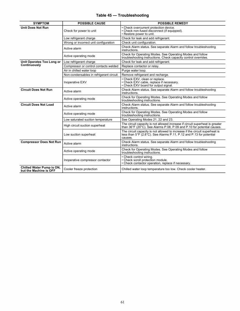
61
Table 45 — Troubleshooting
SYMPTOM POSSIBLE CAUSE POSSIBLE REMEDYUnit Does Not Run
Check for power to unit• Check overcurrent protection device.• Check non-fused disconnect (if equipped).• Restore power to unit.
Low refrigerant charge Check for leak and add refrigerant.Wrong or incorrect unit configuration Check unit configuration.
Active alarm Check Alarm status. See separate Alarm and follow troubleshooting instructions.
Active operating mode Check for Operating Modes. See Operating Modes and follow troubleshooting instructions. Check capacity control overrides.
Unit Operates Too Long or Continuously
Low refrigerant charge Check for leak and add refrigerant.Compressor or control contacts welded Replace contactor or relay.Air in chilled water loop Purge water loop.Non-condensables in refrigerant circuit. Remove refrigerant and recharge.
Inoperative EXV• Check EXV, clean or replace.• Check EXV cable, replace if necessary.• Check EXV board for output signal.
Circuit Does Not Run Active alarm Check Alarm status. See separate Alarm and follow troubleshooting instructions.
Active operating mode Check for Operating Modes. See Operating Modes and follow troubleshooting instructions.
Circuit Does Not Load Active alarm Check Alarm status. See separate Alarm and follow troubleshooting instructions.
Active operating mode Check for Operating Modes. See Operating Modes and follow troubleshooting instructions.
Low saturated suction temperature See Operating Modes 21, 22 and 23.
High circuit suction superheat The circuit capacity is not allowed increase if circuit superheat is greater than 36°F (20°C). See Alarms P.08, P.09 and P.10 for potential causes.
Low suction superheatThe circuit capacity is not allowed to increase if the circuit superheat is less than 5°F (2.8°C). See Alarms P.11, P.12 and P.13 for potential causes.
Compressor Does Not Run Active alarm Check Alarm status. See separate Alarm and follow troubleshooting instructions.
Active operating mode Check for Operating Modes. See Operating Modes and follow troubleshooting instructions.
Inoperative compressor contactor• Check control wiring.• Check scroll protection module.• Check contactor operation, replace if necessary.
Chilled Water Pump is ON, but the Machine is OFF Cooler freeze protection Chilled water loop temperature too low. Check cooler heater.

62
Table 46 — Alarm Codes
PREFIXCODE
SUFFIXCODE DESCRIPTION REASON FOR ALARM ACTION TAKEN
BY CONTROLRESETTYPE PROBABLE CAUSE
A1A2A3A4B1B2B3B4C1C2C3C4
.01 Compressor nn Motor Temperature Too High
Compressor Motor Sensor PTC resistance is greater than 4.5k
Circuit shut down or not allowed to start
ManualCompressor failure, wiring error, operation outside of limits, improper refrigerant charge
.02 Compressor nn Crankcase Heater Failure
Crankcase heater current not detected when required or detected when not required.
Compressor shut down or not allowed to start
ManualWiring error, failed crankcase heater, failed SPM.
.03 Compressor nn High Pressure Switch
High Pressure Switch open.
Circuit shut down or not allowed to start
Manual
Wiring error, closed/restricted discharge valve, improper refrigerant charge, dirty condenser coils, failed outdoor fan motor, discharge pressure transducer inaccuracy
.04 Compressor nn Motor Sensor PTC Out of Range
Compressor Motor Sensor PTC resistance is less than 50 or greater than 17k .
Circuit shut down or not allowed to start
Manual
Wiring error, operation outside of limits, compressor failure, improper refrigerant charge
.05 Compressor nn Power Reset 24-VAC power lost to SPM board.
Compressor shut down or not allowed to start
Automatic Low voltage from main power supply.
.06 Compressor nn Low Control Voltage Alert
24-VAC power to SPM board too low.
Compressor shut down or not allowed to start
Automatic Low voltage from main power supply.
Co
.A1 Loss of Communication with Compressor Board A1
No communication with SPM
Affected compressor is shut down
AutomaticWrong SPM address, wrong unit configuration, wiring error, power loss to SPM.
.A2 Loss of Communication with Compressor Board A2
.A3 Loss of Communication with Compressor Board A3
.A4 Loss of Communication with Compressor Board A4
.B1 Loss of Communication with Compressor Board B1
.B2 Loss of Communication with Compressor Board B2
.B3 Loss of Communication with Compressor Board B3
.B4 Loss of Communication with Compressor Board B4
.C1 Loss of Communication with Compressor Board C1
.C2 Loss of Communication with Compressor Board C2
.C3 Loss of Communication with Compressor Board C3
.C4 Loss of Communication with Compressor Board C4
.E1 Loss of Communication with EXV Board Number 1
No communication with EXV1
Circuit A & B shut down or not allowed to start
AutomaticWrong module address, wrong unit configuration, wiring error, power loss to module.E2 Loss of Communication with
EXV Board Number 2No communication with EXV2
Circuit C shut down or not allowed to start
.F1 Loss of Communication with Fan Board Number 1
No communication with Fan Board 1
Circuit A & B shut down or not allowed to start (060-150, 210-250)Circuit A shut down or not allowed to start (160-190, 275-300) Automatic
Wrong module address, wrong unit configuration, wiring error, power loss to module
.F2 Loss of Communication with Fan Board Number 2
No communication with Fan Board 2
Circuit B shut down or not allowed to start (160-190, 275-300)
.F3 Loss of Communication with Fan Board Number 3
No communication with Fan Board 3
Circuit C shut down or not allowed to start (210-300)

63
Co
.O1 Loss of Communication with Free Cooling Board
No communication with Free Cooling Board
None Automatic Configuration error..O2 Loss of Communication with
Electrical Heaters BoardNo communication with Electrical Heaters Board
.O3 Loss of Communication with Energy Management Board
No communication with Energy Management Board
Disable or not allow EMM Functions(3-Step and 4-20 mA Demand Limit, 4-20 mA and Space Temperature Reset, Occupancy Override, and Ice Build)
AutomaticWrong module address, wrong unit configuration, wiring error, power loss to module
.O4 Loss of Communication with Heat Reclaim Board
No communication with Heat Reclaim Board
Unit shall return to the standard air cooled mode
AutomaticWrong module address, wrong unit configuration, wiring error, power loss to module
Ct
.01 Circuit A Welded Contactor Failure
Controls determine compressor is still running when circuit should be off
EXV, fan control, and pump operate as normal to save compressor until high pressure, freeze, or flow failure conditions occur
ManualOne or more circuit compressor contactors welded closed.
.02 Circuit B Welded Contactor Failure
Controls determine compressor is still running when circuit should be off
EXV, fan control, and pump operate as normal to save compressor until high pressure, freeze, or flow failure conditions occur
ManualOne or more circuit compressor contactors welded closed.
.03 Circuit C Welded Contactor Failure
Controls determine compressor is still running when circuit should be off
EXV, fan control, and pump operate as normal to save compressor until high pressure, freeze, or flow failure conditions occur
ManualOne or more circuit compressor contactors welded closed.
FC.n0 Initial Factory Configuration
Required No configuration Unit not allowed to start Automatic
Configuration error. Password may default to 0113.
.nn Illegal Configuration Wrong or incompatible configuration data
Unit not allowed to start Automatic Configuration error.
MC .nn Master Chiller Configuration Error
Wrong or incompatible configuration data
Unit not allowed to start in Master-Slave Control
Automatic Configuration error. Refer to Table 49.
P
.01 Water Exchanger Freeze Protection
Entering or Leaving Thermistor sensed a temperature at or below freeze point.
Unit shut down or not allowed to start. Chilled Water Pump will be started
Automatic, first occurrence in 24 hours, Manual, if multiple alarms within 24 hours
Faulty thermistor, faulty wiring, low water flow rate, low loop volume, or freeze conditions.
.05 Circuit A Low Suction Temperature
Low Saturated Suction Temperatures sensed for a period of time.
Circuit shut down
Automatic, first occurrence in 24 hours, Manual, if multiple alarms within 24 hours
Faulty transducer, faulty wiring, low water flow rate, low loop volume, fouled cooler, or freeze conditions.
.06 Circuit B Low Suction Temperature
.07 Circuit C Low Suction Temperature
.08 Circuit A High Superheat EXV>98%, Suction Superheat >54°F (30.0°C) and SST<MOP for more than 5 minutes
Circuit shut down Manual
Faulty transducer, faulty thermistor, faulty wiring, faulty EXV, low refrigerant charge, plugged or restricted liquid line.
.09 Circuit B High Superheat
.10 Circuit C High Superheat
.11 Circuit A Low Superheat EXV 5% and Suction Superheat is less than the superheat setting by at least 5°F (2.8°C) or SST>Maximum Operating Pressure for more than 5 minutes
Circuit shut down
Automatic, first occurrence in 24 hours, Manual, if multiple alarms within 24 hours
Faulty transducer, faulty thermistor, faulty wiring, faulty EXV, or incorrect configuration..12 Circuit B Low Superheat
.13 Circuit C Low Superheat
Table 46 — Alarm Codes (cont)
PREFIXCODE
SUFFIXCODE DESCRIPTION REASON FOR ALARM ACTION TAKEN
BY CONTROLRESETTYPE PROBABLE CAUSE
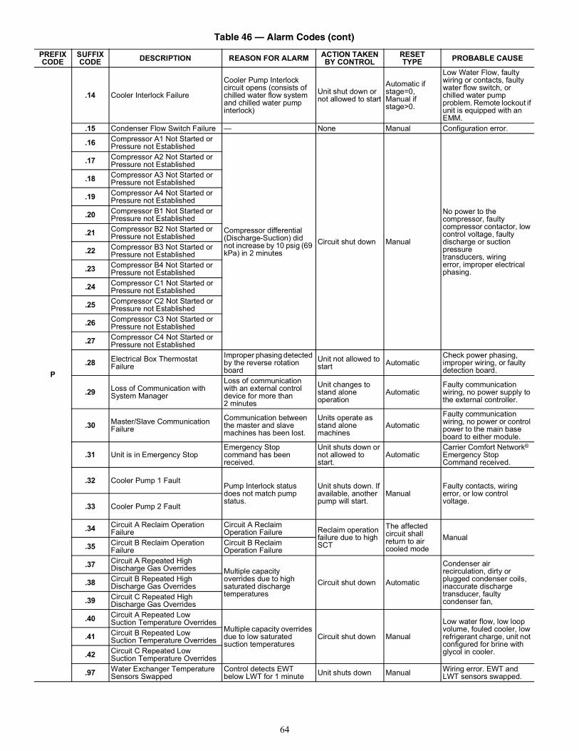
64
P
.14 Cooler Interlock Failure
Cooler Pump Interlock circuit opens (consists of chilled water flow system and chilled water pump interlock)
Unit shut down or not allowed to start
Automatic if stage=0, Manual if stage>0.
Low Water Flow, faulty wiring or contacts, faulty water flow switch, or chilled water pump problem. Remote lockout if unit is equipped with an EMM.
.15 Condenser Flow Switch Failure — None Manual Configuration error.
.16 Compressor A1 Not Started or Pressure not Established
Compressor differential (Discharge-Suction) did not increase by 10 psig (69 kPa) in 2 minutes
Circuit shut down Manual
No power to the compressor, faulty compressor contactor, low control voltage, faulty discharge or suction pressure transducers, wiring error, improper electrical phasing.
.17 Compressor A2 Not Started or Pressure not Established
.18 Compressor A3 Not Started or Pressure not Established
.19 Compressor A4 Not Started or Pressure not Established
.20 Compressor B1 Not Started or Pressure not Established
.21 Compressor B2 Not Started or Pressure not Established
.22 Compressor B3 Not Started or Pressure not Established
.23 Compressor B4 Not Started or Pressure not Established
.24 Compressor C1 Not Started or Pressure not Established
.25 Compressor C2 Not Started or Pressure not Established
.26 Compressor C3 Not Started or Pressure not Established
.27 Compressor C4 Not Started or Pressure not Established
.28 Electrical Box Thermostat Failure
Improper phasing detected by the reverse rotation board
Unit not allowed to start Automatic
Check power phasing, improper wiring, or faulty detection board.
.29 Loss of Communication with System Manager
Loss of communication with an external control device for more than 2 minutes
Unit changes to stand alone operation
AutomaticFaulty communication wiring, no power supply to the external controller.
.30 Master/Slave Communication Failure
Communication between the master and slave machines has been lost.
Units operate as stand alone machines
AutomaticFaulty communication wiring, no power or control power to the main base board to either module.
.31 Unit is in Emergency StopEmergency Stop command has been received.
Unit shuts down or not allowed to start.
AutomaticCarrier Comfort Network® Emergency Stop Command received.
.32 Cooler Pump 1 FaultPump Interlock status does not match pump status.
Unit shuts down. If available, another pump will start.
ManualFaulty contacts, wiring error, or low control voltage..33 Cooler Pump 2 Fault
.34 Circuit A Reclaim Operation Failure
Circuit A Reclaim Operation Failure Reclaim operation
failure due to high SCT
The affected circuit shall return to air cooled mode
Manual.35 Circuit B Reclaim Operation
FailureCircuit B Reclaim Operation Failure
.37 Circuit A Repeated High Discharge Gas Overrides Multiple capacity
overrides due to high saturated discharge temperatures
Circuit shut down Automatic
Condenser air recirculation, dirty or plugged condenser coils, inaccurate discharge transducer, faulty condenser fan,
.38 Circuit B Repeated High Discharge Gas Overrides
.39 Circuit C Repeated High Discharge Gas Overrides
.40 Circuit A Repeated Low Suction Temperature Overrides
Multiple capacity overrides due to low saturated suction temperatures
Circuit shut down Manual
Low water flow, low loop volume, fouled cooler, low refrigerant charge, unit not configured for brine with glycol in cooler.
.41 Circuit B Repeated Low Suction Temperature Overrides
.42 Circuit C Repeated Low Suction Temperature Overrides
.97 Water Exchanger Temperature Sensors Swapped
Control detects EWT below LWT for 1 minute Unit shuts down Manual Wiring error. EWT and
LWT sensors swapped.
Table 46 — Alarm Codes (cont)
PREFIXCODE
SUFFIXCODE DESCRIPTION REASON FOR ALARM ACTION TAKEN
BY CONTROLRESETTYPE PROBABLE CAUSE

65
LEGEND
Pr
.01 Circuit A Discharge Transducer
Measured voltage is 0 vdc
Circuit shut down or not allowed to start.
Automatic
Faulty transducer, wiring error, failed Main Base Board or Fan Board 3. Compressor circuit breaker tripped.
.02 Circuit B Discharge Transducer
.03 Circuit C Discharge Transducer
.04 Circuit A Suction Transducer
.05 Circuit B Suction Transducer
.06 Circuit C Suction Transducer
.07 Circuit A Reclaim Pumpdown Pressure Transducer The affected circuit
shall return to air cooled mode
AutomaticFaulty transducer, wiringerror, failed EMM HR board..08 Circuit B Reclaim Pumpdown
Pressure Transducer
Sr .nn Service Maintenance AlertField programmed elapsed time has expired for maintenance item
None Manual Maintenance required (see Table 50).
th
.01 Water Exchanger Entering Fluid Thermistor Failure
Temperature measured by the controller is less than –40°F (–40°C) or greater than 240°F (115.6°C)
Unit will be shut down or not allowed to start.
AutomaticFaulty thermistor, wiring error, failed Main Base Board..02 Water Exchanger Leaving Fluid
Thermistor Failure
.03 Circuit A Defrost Thermistor Failure
None Automatic Configuration error..04 Circuit B Defrost Thermistor
Failure
.08 Reclaim Condenser Entering Thermistor
Unit shall return to the standard air cooled mode. Automatic
Faulty thermistor, wiringerror, failed EMM HR board..09 Reclaim Condenser Leaving
Thermistor None
.10 OAT Thermistor Failure
Unit is shut down or not allowed to start. Cooler/Pump heaters are energized
AutomaticFaulty thermistor, wiring error, failed Main Base Board.
.11 Master/Slave Common Fluid Thermistor
Dual Chiller deactivated. Master and Slave machines operate in stand alone mode
.12 Circuit A Suction Gas Thermistor
Temperature measured by the controller is less than –40°F (–40°C) or greater than 240°F (115.6°C)
Circuit shut down
AutomaticFaulty thermistor, wiring error, failed Main Base Board or EXV Board
.13 Circuit B Suction Gas Thermistor Circuit shut down
.14 Circuit C Suction Gas Thermistor Circuit shut down
.18 Circuit A Condenser Subcooling Liquid Thermistor Unit shall return to
the standard air cooled mode.
Automatic
Faulty thermistor, wiringerror, failed EMM HR board..19 Circuit B Condenser Subcooling
Liquid Thermistor
.21 Space Temperature Sensor Failure
Temperature Reset based on Space Temperature disabled
Faulty thermistor, wiring error, failed Main Base Board.
V0 xx Circuit A Variable Speed FanMotor Failure See Table 47 — Variable
Speed Fan Motor Alarm Details on page 66Danfoss drive only.
Alert—No actionAlarm—Circuit is stopped
AutomaticSee Table 47 — Variable Speed Fan Motor Alarm Details on page 66.
V1 xx Circuit B Variable Speed FanMotor Failure
V2 xx Circuit C Variable Speed FanMotor Failure
Table 46 — Alarm Codes (cont)
PREFIXCODE
SUFFIXCODE DESCRIPTION REASON FOR ALARM ACTION TAKEN
BY CONTROLRESETTYPE PROBABLE CAUSE
EMM — Energy Management Module OAT — Outdoor Air TemperatureEWT — Entering Water Temperature PTC — Positive Temperature CoefficientEXV — Electronic Expansion Valve SCT — Saturated Condensing TemperatureHR — Heat Reclaim SPM — Scroll Protection ModuleLWT — Leaving Water Temperature SST — Saturated Suction TemperatureMOP — Maximum Operating Pressure

66
Table 47 — Variable Speed Fan Motor Alarm Details, Danfoss Drive
NOTES:1. (X) = Dependent on parameter2. Trip lock condition is an alarm for a condition that could cause
damage to the drive. The alarm can only be reset by cycling powerto the drive.
3. If a warning and an alarm are marked against a code in the table,this means that either a warning occurs before the alarm, or it canbe specified whether it is a warning or an alarm that is to be dis-played for a given fault.
4. Alarms are shown on the drive in parameters 16-90 through 16-95.Parameters can only be accessed with drive display service tool.
NO. DESCRIPTION WARNING ALARM/TRIP
ALARM/TRIP LOCK
PARAMETER REFERENCE
1 10 Volts low X2 Live zero error (X) (X) 6-013 No motor (X) 1-804 Mains phase loss (X) (X) (X) 14-125 DC link voltage high X6 DC link voltage low X7 DC over voltage X X8 DC under voltage X X9 Inverter overloaded X X10 Motor ETR overtemperature (X) (X) 1-9011 Motor thermistor over temperature (X) (X) 1-9012 Torque limit X X13 Over current X X X14 Earth fault X X X15 Hardware mismatch X X16 Short circuit X X17 Control word timeout (X) (X) 8-0418 Start failed X23 Internal fan fault X24 External fan fault X 14-5325 Brake resistor short-circuited X26 Brake resistor power limit (X) (X) 2-1327 Brake chopper short-circuited X X28 Brake check (X) (X) 2-1529 Drive over temperature X X X30 Motor phase U missing (X) (X) (X) 4-5831 Motor phase V missing (X) (X) (X) 4-5832 Motor phase W missing (X) (X) (X) 4-5833 Inrush fault X X34 Field bus communication fault X X35 Out of frequency range X X36 Mains failure X X37 Phase imbalance X X38 Internal fault X X39 Heatsink sensor X X40 Overload of Digital Output Terminal 27 (X) 5-00, 5-0141 Overload of Digital Output Terminal 29 (X) 5-00, 5-0242 Overload of Digital Output Terminal On X30/6 (X) 5-3242 Overload of Digital Output Terminal On X30/7 (X) 5-3346 Power card supply X X47 24 V supply low X X X48 1.8 V supply low X X49 Speed limit X (X) 1-8650 AMA calibration failed X51 AMA check Unom and Inom X52 AMA low Inom X53 AMA motor too big X54 AMA motor too small X55 AMA parameter out of range X56 AMA interrupted by user X57 AMA timeout X58 AMA internal fault X X59 Current limit X60 External Interlock X

67
Table 47 — Variable Speed Fan Motor Alarm Details, Danfoss Drive (cont)
NOTES:1. (X) = Dependent on parameter2. Trip lock condition is an alarm for a condition that could cause
damage to the drive. The alarm can only be reset by cycling powerto the drive.
3. If a warning and an alarm are marked against a code in the table,this means that either a warning occurs before the alarm, or it canbe specified whether it is a warning or an alarm that is to be dis-played for a given fault.
4. Alarms are shown on the drive in parameters 16-90 through 16-95.Parameters can only be accessed with drive display service tool.
NO. DESCRIPTION WARNING ALARM/TRIP
ALARM/TRIP LOCK
PARAMETER REFERENCE
62 Output frequency at maximum limit X64 Voltage limit X65 Control board over-temperature X X X66 Heat sink temperature low X67 Option configuration has changed X69 Power card temperature X X70 Illegal FC configuration X71 PTC 1 Safe Stop X X72 Dangerous failure X73 Safe stop auto restart76 Power unit setup X79 Illegal PS configuration X X80 Drive initialized to default value X91 Analog input 54 wrong settings X92 NoFlow X X 22-293 Dry pump X X 22-294 End of curve X X 22-595 Broken belt X X 22-696 Start delayed X 22-797 Stop delayed X 22-798 Clock fault X 0-7201 Fire M was active202 Fire M limits exceeded203 Missing motor204 Locked rotor243 Brake IGBT X X244 Heatsink temperature X X X245 Heatsink sensor X X246 Power card supply X X247 Power card temperature X X248 Illegal PS configuration X X

68
Fig. 34 — Alarm Description
DIAGNOSTIC ALARM CODES AND POSSIBLE CAUSESMotor Temperature Too HighA1.01 — Compressor A1A2.01 — Compressor A2A3.01 — Compressor A3A4.01 — Compressor A4B1.01 — Compressor B1B2.01 — Compressor B2B3.01 — Compressor B3B4.01 — Compressor B4C1.01 — Compressor C1C2.01 — Compressor C2C3.01 — Compressor C3C4.01 — Compressor C4Criteria for TripThe alarm criterion is checked whether the compressor is ON orOFF. This alarm will be generated if the scroll protection module(SPM) detects a compressor motor PTC (positive temperature co-efficient) resistance greater than 4500 ohms, indicating that themotor temperature is too high.Action to be Taken The circuit shuts down immediately or is not allowed to start.Reset Method Manual. PTC resistance must be less than 2500 ohmsPossible CausesIf this condition is encountered, check the following items:• Check for a PTC thermistor failure.• Check for a compressor motor failure.• Check for a wiring error.• Check wiring terminations for corrosion.• Check for operation outside of the limits.• Check for condenser air recirculation.• Check the circuit for proper charge.• Check the EXV for proper operation.
• Check the EXV input devices, pressure transducer andtemperature for accuracy.
• Check the liquid line filter drier for a restriction.Crankcase Heater FailureA1.02 — Compressor A1A2.02 — Compressor A2A3.02 — Compressor A3A4.02 — Compressor A4B1.02 — Compressor B1B2.02 — Compressor B2B3.02 — Compressor B3B4.02 — Compressor B4C1.02 — Compressor C1C2.02 — Compressor C2C3.02 — Compressor C3C4.02 — Compressor C4Criteria for TripThe alarm criteria are checked whether the compressor is ON orOFF. The scroll protection module (SPM) monitors crankcaseheater current draw. This family of alarms is generated if one ofthe following criteria is detected:1. The SPM fails to detect a crankcase current draw of at least
0.5 amp while the crankcase heater is ON.2. The SPM detects a crankcase current draw of at least 0.5 amp
while the crankcase heater is OFF. The current is sensed inter-nally on the SPM.
Action to be TakenIf a fault is detected, the affected compressor will be shut down ornot allowed to start.Reset Method ManualPossible CausesIf this condition is encountered, check the following items:• Check the wiring to the crankcase heater.• Check the crankcase heater for operation.• Check the SPM crankcase heater output operation.• Confirm unit configuration.
High Pressure SwitchA1.03 — Compressor A1A2.03 — Compressor A2A3.03 — Compressor A3A4.03 — Compressor A4B1.03 — Compressor B1B2.03 — Compressor B2B3.03 — Compressor B3B4.03 — Compressor B4C1.03 — Compressor C1C2.03 — Compressor C2C3.03 — Compressor C3C4.03 — Compressor C4Criteria for TripThe alarm criterion is checked whether the circuit is ON or OFF.This alarm will be generated if the circuit high-pressure switch(HPS) opens. The scroll protection module (SPM) monitors theHPS. The 30RB units employ one HPS for each circuit. The HPSsignal is connected to all of the SPM modules of the circuit.Action to be TakenThe circuit shuts down immediately or is not allowed to start.Reset Method Manual
Alarm Descriptor th
Alarm SuffixCode Number to identify source
.01Alarm Prefix
A1 – Compressor A1 FailureA2 – Compressor A2 FailureA3 – Compressor A3 FailureA4 – Compressor A4 FailureB1 – Compressor B1 FailureB2 – Compressor B2 FailureB3 – Compressor B3 FailureB4 – Compressor B4 FailureC1 – Compressor C1 FailureC2 – Compressor C2 FailureC3 – Compressor C3 FailureC4 – Compressor C4 FailureCo – Communication FailureCt – Circuit Welded Contactor FailureFC – Factory Configuration ErrorMC – Master Chiller Configuration ErrorP – Process FailurePr – Pressure Transducer FailureSr – Service Notificationth – Thermistor FailureV0 – Circuit A Variable Speed Fan Motor FailureV1 – Circuit B Variable Speed Fan Motor FailureV2 – Circuit C Variable Speed Fan Motor Failure
Alarm

69
Possible Causes If this condition is encountered, check the following items:• Check the wiring of the high pressure switch circuit. Be sure
the HPS is connected to all of the SPM boards in the circuit.• Check the maximum condensing temperature (MCT) for
the proper setting.• Check for non-condensables in the refrigerant circuit.• Check for condenser air re-circulation.• Check for the proper refrigerant charge (overcharged).• Check for operation beyond the limit of the machine.• Check the condenser coils for debris or restriction.• Check the condenser fans and motors for proper rotation
and operation.• Check the discharge service valve to be sure that it is open. A
closed or restricted valve is a potential high pressure trip.• Check the discharge pressure transducer for accuracy.• Confirm unit configuration.
Motor Sensor PTC Out of RangeA1.04 — Compressor A1 A2.04 — Compressor A2 A3.04 — Compressor A3 A4.04 — Compressor A4 B1.04 — Compressor B1 B2.04 — Compressor B2 B3.04 — Compressor B3 B4.04 — Compressor B4 C1.04 — Compressor C1 C2.04 — Compressor C2 C3.04 — Compressor C3 C4.04 — Compressor C4 Criteria for Trip The alarm criterion is checked whether the circuit is ON or OFF.The scroll protection module (SPM) monitors the compressor mo-tor temperature. This alarm will be generated if the motor sensorPTC in the compressor resistance is less than 50 ohms or greaterthan 17,000 ohms.Action to be Taken The circuit shuts down immediately or not allowed to start.Reset MethodManualPossible CausesIf this condition is encountered, check the following items:• Check the sensor wiring to the scroll compressor protec-
tion module (SPM).• Check for a faulty SPM.• Check for a compressor failure.• Check for noncondensables in the refrigerant circuit.• Check for condenser air re-circulation.• Check for the proper refrigerant charge (overcharged).• Check for operation beyond the limit of the machine.• Check the condenser coils for debris or restriction.• Check the condenser fans and motors for proper rotation
and operation.• Check the discharge service valve to be sure that it is open.• Check the discharge pressure transducer for accuracy.• Confirm unit configuration.
SPM Board Power ResetA1.05 – Compressor A1A2.05 – Compressor A2A3.05 – Compressor A3A4.05 – Compressor A4B1.05 – Compressor B1B2.05 – Compressor B2B3.05 – Compressor B3B4.05 – Compressor B4C1.05 – Compressor C1C2.05 – Compressor C2C3.05 – Compressor C3C4.05 – Compressor C4Criteria for TripThe alarm criterion is checked whether the compressor is ON orOFF. The scroll protection module (SPM) monitors the 24 vac atthe compressor through the high pressure switch input channel.This alarm will be generated if the main base board receives a sig-nal from the SPM board indicating that the compressor wentthrough a power cycle.Action to be TakenThe compressor is shut down immediately or not allowed to start.Reset Method AutomaticPossible CausesIf this condition is encountered, check the following items:• Check the voltage from the main three phase power supply.• Check the 24 vac wiring connections to the scroll com-
pressor protection module (SPM).• Check for a faulty SPM.
SPM Board Low Control Voltage AlertA1.06 – Compressor A1A2.06 – Compressor A2A3.06 – Compressor A3A4.06 – Compressor A4B1.06 – Compressor B1B2.06 – Compressor B2B3.06 – Compressor B3B4.06 – Compressor B4C1.06 – Compressor C1C2.06 – Compressor C2C3.06 – Compressor C3C4.06 – Compressor C4Criteria for Trip The alarm criterion is checked whether the compressor is ON orOFF. The scroll protection module (SPM) monitors the 24 vac atthe compressor through the high pressure switch input channel.This alarm will be generated if the main base board receives a sig-nal from the SPM board indicating that the 24 vac level was lowerthan the allowed minimum threshold.Action to be Taken The compressor is shut down immediately or not allowed to startas to prevent any contactor chattering/welding from occurring.Reset MethodAutomaticPossible CausesIf this condition is encountered, check the following items:• Check the voltage from the main three phase power supply.• Check the 24 vac wiring connections to the scroll com-
pressor protection module (SPM).• Check for a faulty SPM.

70
Loss of Communication with CompressorCo.A1 — Board A1Co.A2 — Board A2Co.A3 — Board A3Co.A4 — Board A4Co.B1 — Board B1Co.B2 — Board B2Co.B3 — Board B3Co.B4 — Board B4Co.C1 — Board C1Co.C2 — Board C2Co.C3 — Board C3Co.C4 — Board C4Criteria for TripThe alarm criterion is tested whether the unit is ON or OFF. Ifcommunication with the scroll compressor protection module(SPM) is lost for a period of 10 seconds, the alarm will begenerated.Action to be TakenThe affected compressor will be shut down.Reset MethodAutomatic, if communication is established, the compressor, ifcalled for will start normally.Possible CausesIf this condition is encountered, check the following items:• Check the power supply to the affected SPM.• Check the address of the SPM to be sure that it is correct.• Check the Local Equipment Network (LEN) wiring to be
sure that it is connected properly.• Confirm unit configuration.
Co.E1— Loss of Communication with EXV Board Number 1Criteria for TripThe alarm criterion is tested whether the unit is ON or OFF. Ifcommunication with EXV1 is lost for a period of 10 seconds, thealarm will be triggered.Action to be Taken If running, Circuit A and B will shut down normally. If Circuit Aor Circuit B is not operating, it will not be allowed to start.Reset Method Automatic, if communication is established, the unit will startnormally.Possible CausesIf this condition is encountered, check the following items:• Check the power supply to EXV1.• Check the address of the EXV1 to be sure that it is correct.• Check the Local Equipment Network (LEN) wiring to be
sure that it is connected properly.• Confirm unit configuration.
Co.E2 — Loss of Communication with EXV Board Number 2Criteria for Trip The alarm criterion is tested whether the unit is ON or OFF, on30RB210-300 units only.Action to be Taken If communication with EXV Board 2 is lost for a period of 10 sec-onds, the alarm will be triggered. If running, Circuit C will shutdown normally. If Circuit C is not running, it will not be allowedto start.Reset Method Automatic, if communication is established, the unit will startnormally.
Possible CausesIf this condition is encountered, check the following items:• Check the power supply to EXV Board 2.• Check the address of the EXV Board 2 to be sure that it is
correct.• Check the Local Equipment Network (LEN) wiring to be sure
that it is connected properly.• Confirm unit configuration.
Co.F1 — Loss of Communication with Fan Board Number 1Criteria for TripThe criterion is tested whether the unit is ON or OFF. If communi-cation with Fan Board 1 is lost for a period of 10 seconds, thealarm will be triggered.Action to be Taken For 30RB060-150 and 30RB210-250, Circuit A and B will shutdown normally if they are running. For 30RB160-190 and30RB275-300, Circuit A will shut down normally if it is running.If the circuit or circuits controlled by the board are not running,then they will not be allowed to start.Reset Method Automatic, if communication is established, the unit will startnormally.Possible CausesIf this condition is encountered, check the following items:• Check the power supply to Fan Board 1.• Check the address of the Fan Board 1 to be sure that it is
correct.• Check the Local Equipment Network (LEN) wiring to be
sure that it is connected properly.• Confirm unit configuration.
Co.F2 — Loss of Communication with Fan Board Number 2Criteria for Trip The criterion is tested whether the unit is ON or OFF and on30RB160-190, 275, and 300 only. Action to be TakenIf communication with Fan Board 2 is lost for a period of 10 sec-onds, the alarm will be triggered. If running, Circuit B will shutdown normally for 30RB160-190, 275 and 300. If Circuit B is notrunning for 30RB160-190, 275 and 300, then it will not be al-lowed to start.Reset MethodAutomatic, if communication is established, the unit will start nor-mally.Possible Causes If this condition is encountered, check the following items:• Check the power supply to Fan Board 2.• Check the address of the Fan Board 2 to be sure that it is
correct.• Check the Local Equipment Network (LEN) wiring to be
sure that it is connected properly.• Confirm unit configuration.
Co.F3 — Loss of Communication with Fan Board Number 3Criteria for Trip The criterion is tested whether the unit is ON or OFF, and on30RB210-300 machines only. If communication with Fan Board 3is lost for a period of 10 seconds, the alarm will be triggered.Action to be Taken If running, Circuit C will shut down normally for 30RB210-300.If the circuit is not running for 30RB210-300, then it will not beallowed to start.

71
Reset Method Automatic, if communication is established, the unit will start nor-mally.Possible Causes If this condition is encountered, check the following items:• Check the power supply to Fan Board 3.• Check the address of the Fan Board 3 to be sure that it is
correct.• Check the Local Equipment Network (LEN) wiring to be
sure that it is connected properly.• Confirm unit configuration.
Co.O1 — Loss of Communication with Free Cooling BoardCriteria for TripThis alarm is for a free cooling machine only. This feature is notsupported for a cooling only machine.Action to be TakenNoneReset Method AutomaticPossible CausesIf this condition is encountered, confirm unit configuration.Co.O2 — Loss of Communication with Electrical Heaters BoardCriteria for Trip This alarm is for a heat pump machines only. This feature is notsupported for a cooling only machine.Action to be Taken NoneReset MethodAutomaticPossible CausesIf this condition is encountered, confirm unit configuration.Co.O3 — Loss of Communication with Energy Management BoardCriteria for TripThe criterion is tested whether the unit is ON or OFF and when afunction that requires the energy management module (EMM) isconfigured. If communication with the EMM is lost for a period of10 seconds, the alarm will be triggered.Action to be TakenIf any function controlled by the EMM (3-Step and 4-20 mA De-mand Limit, 4-20 mA and Space Temperature Reset, OccupancyOverride, and Ice Build) is active, that function will be terminated.If an EMM function is programmed, and communication is lost,the function will not be allowed to start.Reset Method Automatic, if communication is established, the functions will beenabled.Possible CausesIf this condition is encountered, check the following items:• Check configuration to see if the EMM is installed, (Con-
figurationUNITEMM). If (EMM=YES), check for acontrol option that requires the EMM that may be enabled.Correct configuration if not correct.
• Check the power supply to EMM.• Check the address of the EMM to be sure that it is correct.
• Check the Local Equipment Network (LEN) wiring to besure that it is connected properly.
• Check unit configuration to be sure that no options that re-quire the EMM are enabled.
Co.O4 — Loss of Communication with Heat Reclaim BoardCriteria for TripThis alarm is tested whether the unit is ON or OFF and when theunit is configured for Heat Reclaim. If communication with theheat reclaim board is lost for a period of 10 seconds, the alarm willbe triggered.Action to be Taken The unit will return to the air cooled mode.Reset MethodAutomatic, when communication is established, the functions willbe enabled.Possible CausesIf this condition is encountered, check the following items:• Check the power supply to heat reclaim board.• Check the Local Equipment Network (LEN) wiring to be
sure that it is connected properly.• Check unit configuration to be sure that Heat Reclaim is en-
abled and unit does NOT contain the Heat Reclaim option.Welded Contactor FailureCt.01 – Circuit ACt.02 – Circuit BCt.03 – Circuit CCriteria For TripThis alarm is tested for when the circuit is off (all compressorsswitched to off). The algorithm will evaluate saturated suction andsaturated condensing temperatures to determine if the compressoris still running even though it has been commanded off.Action to be Taken1. Unit capacity will go to and remain at 0%. The EXV, fan con-
trol, and cooler pump will continue their normal operation.2. If a high pressure, cooler flow, or cooler freeze failure occurs,
then circuit operation is disabled. The critical alarm relay willbe energized in order to shut off the main power supply.
Reset MethodReset is manual.FC.n0 — Initial Factory Configuration RequiredCriteria for Trip The criterion is tested whether the unit is ON or OFF. The alarmwill be generated if Configuration UNITTONS=0.Action to be TakenThe unit is not allowed to start.Reset MethodAutomatic after factory configuration is complete. The configura-tion must be manually completed. The password may default to0113.Possible CausesIf this condition is encountered, confirm the unit configuration.FC.nn — Illegal ConfigurationCriteria for TripThe criterion is tested whether the unit is ON or OFF. The alarmwill be generated if the one of the following configuration errors isdetected by the control. The “nn” refers to the error code listed inTable 48.

72
Table 48 — Illegal Configuration Alarm Code
Action to be Taken The unit is not allowed to start.Reset MethodAutomatic after factory reconfiguration is completed. A power cy-cle may be required.Possible CausesIf this condition is encountered, confirm the unit configuration.MC.nn — Master Chiller Configuration ErrorCriteria for TripThe criterion is tested whether the unit is ON or OFF. The unitsmust be configured as a Master and Slave machine (Configura-tionRSETMSSL=1 and ConfigurationRSETMS-SL=2), and one of the following configuration errors has beenfound. The “nn” refers to the error code listed in Table 49.Action to be TakenUnit not allowed to start in Master Slave control.Reset Method AutomaticPossible CausesIf this condition is encountered, confirm proper configuration.P.01 — Water Exchanger Freeze ProtectionCriteria for TripThe alarm criteria are checked whether the unit is ON or OFF. Ifthe entering or leaving water thermistor senses a temperature atthe freeze point or less, the alarm will be generated. For a freshwater system (Configuration SERVFLUD=1), the freezepoint is 34°F (1.1°C). For medium temperature brine systems(Configuration SERVFLUD=2), the freeze point is BrineFreeze Set Point (ConfigurationSERVLOSP).Action to be Taken Unit shut down or not allowed to start. Chilled water pump will bestarted.Reset Method Automatic, first occurrence in 24 hours if LWT rises to 6°F (3°C)above set point. Manual, if more than one occurrence in 24 hours.Possible CausesIf this condition is encountered, check the following items:• Check the entering and leaving fluid thermistors for accuracy.• Check the water flow rate.
• Check loop volume. Low loop volume at nominal flowrates can in extreme cases bypass cold water to the cooler.
• Check for freezing conditions.• Check heater tape and other freeze protection items for
proper operation.• Check glycol concentration and adjust LOSP accordingly.• If the Leaving Water Set Point is above 40°F (4.4°C) and
there is glycol in the loop, consider using the MediumTemperature Brine option (ConfigurationSERVFLUD=2) to utilize the brine freeze point in-stead of 34°F (1.1°C).
Low Suction TemperatureP.05 — Circuit A P.06 — Circuit B P.07 — Circuit C Criteria for TripThe criteria are tested whether the circuit is ON. This alarm is gen-erated if one of the following criteria is met:• If the circuit Saturated Suction Temperature is below –13°F
(–25°C) for more than 30 seconds.• If the circuit Saturated Suction Temperature is below –22°F
(–30°C) for more than 8 seconds.• If the circuit Saturated Suction Temperature is below –40°F
(–40°C) for more than 3 seconds.Action to be Taken The circuit is shut down immediately.Prior to the alarm trip, thecontrol will take action to avoid the alarm. See Operating Modes21, 22 and 23 on page 47.Reset Method Automatic, first occurrence in 24 hours. Manual, if more than oneoccurrence in 24 hours.Possible CausesIf this condition is encountered, check the following items:• Check the sensor wiring to Main Base Board (P.05 and
P.06) or Fan Board 3 (P.07).• Check the board for a faulty channel.• Check for a faulty transducer.• Check cooler water flow.• Check loop volume.• Check EXV operation.• Check for a liquid line refrigerant restriction, filter drier,
service valve, etc.• Check the refrigerant charge.• If the Leaving Water Set Point is above 40°F (4.4°C) and
there is glycol in the loop, consider using the MediumTemperature Brine option (ConfigurationSERVFLUD=2) to utilize the brine freeze point insteadof 34°F (1.1°C).
FC ERROR CODE
DESCRIPTION
01 Unit size is unknown.02 Reclaim option selected for Heat Pump machine.
03 Hot Gas Bypass configured for a Heat Pump machine.
04 Number of Fans controlled by Motormaster® control is greater than expected.

73
Table 49 — Master/Slave Alarm Code
LEGEND
High SuperheatP.08 — Circuit A P.09 — Circuit B P.10 — Circuit C Criteria for TripThe criteria are tested whether the circuit is ON. This alarm is gen-erated if all of the following criteria are met:1. The EXV position is equal to or greater than 98%.2. The circuit’s Suction Superheat (Suction Gas Temperature –
Saturated Suction Temperature) is greater than 54°F(30.0°C).
3. The circuit’s Saturated Suction Temperature is less than Max-imum Operating Pressure (MOP) set point (Configura-tionSERVMOP) for more than 5 minutes.
Action to be TakenThe circuit is shut down normally.Reset MethodManual.Possible CausesIf this condition is encountered, check the following items:• Check the suction pressure transducer wiring to Main Base
Board (P.08 and P.09) or Fan Board 3 (P.10).• Check the board for a faulty channel.• Check for a faulty transducer.• Check the suction gas thermistor wiring to EXV Board 1
(P.08 and P.09) or to EXV Board 2 (P.10)• Check the suction gas thermistor sensor for accuracy.• Check for EXV Board 1 (P.08 and P.09) or EXV Board 2
(P.10) faulty channel. • Check EXV operation.• Check for a liquid line refrigerant restriction, filter drier,
service valve, etc.• Check the refrigerant charge.
Low SuperheatP.11 — Circuit A P.12 — Circuit B P.13 — Circuit C
Criteria for TripThe criteria are tested whether the circuit is ON. This alarm is gen-erated if the following criterion is met:The EXV position is equal to or less than 5% and the circuit’s Suc-tion Superheat (Suction Gas Temperature – Saturated SuctionTemperature) is less than the Suction Superheat Set Point (Config-urationSERVSHP.A, Configuration SERVSHP.B, orConfigurationSERVSHP.C) by at least 5°F (2.8°C) or thecircuit Saturated Suction Temperature is greater than MaximumOperating Pressure (MOP) set point (ConfigurationSERVMOP) for more than 5 minutes.Action to be TakenThe circuit is shut down normally.Reset MethodAutomatic, first occurrence in 24 hours. Manual, if more than oneoccurrence in 24 hours.Possible CausesIf this condition is encountered, check the following items:• Check the suction pressure transducer wiring to Main Base
Board (P.11 and P.12) or Fan Board 3 (P.13).• Check the board for a faulty channel.• Check for a faulty transducer.• Check the suction gas thermistor wiring to EXV Board 1
(P.08 and P.09) or to EXV Board 2 (P.10)• Check the suction gas thermistor sensor for accuracy.• Check for EXV Board 1 (P.11 and P.12) or EXV Board 2
(P.13) faulty channel. • Check EXV operation.• Confirm Maximum Operating Pressure Set Point.• Check the refrigerant charge.
P.14 — Cooler Interlock FailureCriteria for TripThe criteria are tested whether the unit is ON or OFF. This algo-rithm monitors the cooler flow switch circuit, which may includefield-installed cooler pump interlock (PMPI) contacts. The pumpinterlock and flow switch are wired in series, therefore either de-vice can cause a cooler interlock failure.
MC ERROR CODE
MASTER SLAVE DESCRIPTION
01 X X The master or slave water pump is not configured while the control of the lag unit pump is required(lag_pump = 1)
02 X Master and slave units have the same network address.03 X There is no slave configured at the slave address04 X Slave pump_seq incorrect configuration
05 X There is a conflict between the master and the slave LWT option: the master is configured for EWT control while the slave is configured for LWT control.
06 X There is a conflict between the master and the slave LWT option: the master is configured for LWT control while the slave is configured for EWT control.
07 X There is a conflict between the master and the slave pump option: the master is configured for lag pump control while the slave is not configured for lag pump control.
08 X There is a conflict between the master and the slave pump option: the master is not configured for lag pump control while the slave is configured for lag pump control.
09 X X The slave chiller is in local or remote control (chilstat = 3)10 X X The slave chiller is down due to fault (chilstat = 5)11 X The master chiller operating type is not Master: master_oper_typ and master_status = off12 X X No communication with slave.13 X Master and slave heat/cool status are not the same.
EWT — Entering Water TemperatureLWT — Leaving Water Temperature

74
This alarm is generated if one of the following criteria is met:1. The circuit (flow switch and optional pump interlock installed
at TB5-1 and 2) fails to close within the OFF to ON delay(ConfigurationOPTNDELY).
2. If the unit is the lag chiller under Master/Slave Control andthe circuit fails to close within 1 minute after its pump is com-manded ON.
3. The circuit opens while the machine is ON.4. If the remote interlock switch is CLOSED while the
machine is ON (units with EMM only).5. If the machine is configured for Cooler Pump Control and the
circuit does not open within 2 minutes.6. The circuit fails to close within the OFF to ON delay
when the cooler pump has been commanded ON forfreeze protection.
Action to be TakenThe unit is shut down immediately, or not allowed to start.Reset MethodAutomatic, if the alarm occurs while the machine is at Stage 0(no compressors ON). Manual reset if machine was at Stage 1 orgreater.Possible CausesIf this condition is encountered, check the following items:• Check the chilled water flow switch operation.• Check for water flow. Be sure all water isolation valves are
open. Check the water strainer for a restriction.• Check the interlock wiring circuit.• Check for a power supply to the pump.• Check for a control signal to the pump controller.• Check the chilled water pump operation.• Check the cooler pump contactor for proper operation.
P.15 — Condenser Flow Switch FailureCriteria for TripCondenser flow switch has not closed within 1 minute after con-denser pump output has energized or opens during normal opera-tion. This alarm is for units with the heat reclaim option only.Action to be TakenThe unit will return to the air cooled mode.Reset MethodManual.Possible CausesIf this condition is encountered, check the following items:• Check the condenser water flow switch operation.• Check for low water flow. Be sure all water isolation
valves are open.• Check for plugged water strainer.• Check the interlock wiring circuit.• Check the power supply to the pump.• Check for a control signal to the pump starter.• Check the condenser water pump operation.• Check the condenser pump contactor for proper operation.
Compressor Not Started or Pressure Not Established P.16 — Compressor A1 P.17 — Compressor A2 P.18 — Compressor A3 P.19 — Compressor A4 P.20 — Compressor B1 P.21 — Compressor B2 P.22 — Compressor B3 P.23 — Compressor B4
P.24 — Compressor C1 P.25 — Compressor C2 P.26 — Compressor C3 P.27 — Compressor C4 Criteria for Trip The criteria are tested whether the unit is ON or in Service Test.This algorithm monitors the pressure differential across the com-pressor to prove proper rotation of the compressor.During normal operation with the start of a compressor, the dis-charge pressure for the circuit or the compressor differential(Discharge Pressure – Suction Pressure) must increase 10 psig(69 kPa) after 2 minutes. If this criterion is not met, the alarm isgenerated.Action to be Taken The circuit is shut down immediately.Reset MethodManualPossible CausesIf this condition is encountered, check the following items:• Check for power to the compressor.• Check control voltage to the compressor contactor. On 208-
volt systems, be sure the proper tap on TRAN1 is utilized.• Check for proper electrical phasing of the unit power sup-
ply.• Check the compressor contactor operation.• Check the discharge and suction pressure transducers for
accuracy.• Check the wiring and location of the discharge and suction
pressure transducers.P.28 — Electrical Box Thermostat Failure/Reverse RotationCriteria for TripThe criterion is tested whether the unit is ON. This alarm is gener-ated if the signal is open.Action to be Taken The unit is not allowed to start.Reset Method Automatic, once the phasing is corrected.Possible CausesIf this condition is encountered, check the following items:• Check the power wiring for proper phasing.• Check sensor wiring to reverse rotation protection board.
P.29 — Loss of Communication with System ManagerCriteria for TripThe criterion is tested whether the unit is ON or OFF. This alarmis generated if the System Manager had established communica-tions with the machine and is lost for more than 2 minutes.Action to be TakenThe action to be taken by the control depends on the configura-tion. If Auto Start when SM lost is enabled, (Configura-tionSERVAU.SM=YES), then the unit will force the CCNChiller Start Stop (Run Status R.CCNCH.SS) to ENBL andclear all forced points from the System Manager. The unit will re-vert to stand-alone operation.Reset Method Automatic, once communication is re-established.Possible Causes If this condition is encountered, check the following items:• Check communication wiring.• Check the power supply to the System Manager and unit
controls.

75
P.30 — Master/Slave Communication FailureCriteria for TripThe criterion is tested whether the units are ON or OFF and aMaster and Slave machine has been configured (ConfigurationRSETMSSL=1 and ConfigurationRSETMSSL=2). Ifcommunication is lost for more than 3 minutes, this alarm isgenerated.Action to be TakenDual chiller control will be disabled and each unit will operate inStand-Alone mode.Reset MethodAutomatic, once communication is re-established.Possible CausesIf this condition is encountered, check the following items:• Check the CCN wiring.• Check for control power to each Main Base Board, Master
and Slave.• Confirm correct configuration.
P.31 — Unit is in Emergency StopCriteria for TripThe criterion is tested whether the units are ON or OFF and themachine receives a Carrier Comfort Network® (CCN) commandfor an Emergency Stop.Action to be TakenUnit will stop, or not allowed to start.Reset Method Automatic, once a return to normal command is received.Possible CausesIf this condition is encountered, check for CCN Emergency Stopcommand.Cooler Pump FaultP.32 — Pump 1 FaultP.33 — Pump 2 FaultCriteria for TripThe criterion is tested whether the units are ON or OFF. Thisalarm will be generated if the cooler pump interlock opens. Whenstarting the pump, the control must read a closed circuit for 3 con-secutive reads. If the pump is operating and the circuit opens, thealarm will be generated immediately.Action to be TakenThe pump and machine will be shut down. If there is anotherpump available, the control will start that pump, restart the ma-chine and clear the alarm. If no other pump is available, the unitwill remain OFF. Reset MethodManual.Possible CausesIf this condition is encountered, check the following items:• Check the interlock wiring circuit.• Check for a control signal to the pump controller.• Check the cooler pump contactor for proper operation.• Check control voltage for proper voltage. On 208-volt sys-
tems, be sure the proper tap on TRAN1 is utilized.Reclaim Operation FailureP.34 — Circuit A P.35 — Circuit B Criteria for TripReclaim operation failure due to high SCT. This alarm is for unitswith the heat reclaim option only.
Action to be Taken The affected circuit will return to air cooled mode.Reset MethodManual.Possible CausesIf this condition is encountered, check the following items:• Check for low water flow. Be sure all water isolation
valves are open.• Check for plugged water strainer.• Check for fouled tubes in reclaim condenser.
Repeated High Discharge Gas OverridesP.37 — Circuit A P.38 — Circuit B P.39 — Circuit C Criteria for TripThe criterion is tested when the circuit is ON. This alarm will betripped if the circuit capacity is reduced more than 8 times in 30minutes due to high discharge gas temperatures. If no override oc-curs in a 30-minute period, the counter is reset.Action to be TakenThe affected circuit will be shut down.Reset MethodAutomatic, after 30 minutes. If the alarm is cleared via the Manualmethod, the counter will be reset to zero.Possible Causes If this condition is encountered, check the following items:• Check the maximum condensing temperature (MCT) for
the proper setting.• Check for noncondensables in the refrigerant circuit.• Check for condenser air re-circulation.• Check for the proper refrigerant charge (overcharged).• Check for operation beyond the limit of the machine.• Check the condenser coils for debris or restriction.• Check the condenser fans and motors for proper rotation
and operation.• Check the discharge service valve to be sure that it is open.
Check the discharge pressure transducer for accuracy.• Confirm unit configuration.
Repeated Low Suction Temperature OverridesP.40 – Circuit AP.41 – Circuit BP.42 – Circuit CCriteria for Trip This alarm was added in software version 1.09. The criterion is ac-tive when circuit is ON. If the circuit’s capacity is reduced morethan 6 times by the Capacity Override 23 (Circuit A), 24 (CircuitB), or 25 (Circuit C) for the respective circuit, without at least 30minutes elapsing between the capacity reductions, the alarm istriggered. If at least 30 minutes elapse without a reduction in ca-pacity, the counter is reset to zero.Action to be TakenCircuit shut down.Reset MethodManual.Possible CausesIf this condition is encountered, check the following items:• Confirm unit configuration.• Check EXV operation.• Check for a liquid line refrigerant restriction, service valve
partially closed, filter drier with excessive pressure drop.

76
• Check the refrigerant charge.• Check suction pressure transducer accuracy.• Check return gas thermistor accuracy.• Check Circuit Superheat Set Point (Configuration
SERVSHP.A, SHP.B, or SHP.C).• Check if system contains antifreeze (Configuration
SERVFLUD=2).• Check Brine Freeze Set Point (Configuration
SERVLOSP) if an antifreeze solution is used.• Check fluid flow rate.• Check strainer for a restriction, clean if necessary.• Check for cooler fouling.• Check compressor oil level. If oil level is above the top of
the sightglass, then oil may be logging in the cooler. Ad-just oil level in compressor(s).
P.97 — Water Exchanger Temperature Sensors SwappedCriteria for TripThe alarm criterion is checked when the chiller is ON and one ormore compressors is running. This alarm will be tripped if the en-tering water temperature is less than the leaving water temperaturefor more than 1 minute.Action to be TakenThe chiller is shut down immediately.Reset MethodManualPossible CausesIf this condition is encountered, check the following items:• Check LWT and EWT wiring at main base board (connec-
tor J6, channels 1,2).• Check for a faulty entering or leaving water temperature
sensor.• Check cooler nozzles for proper water temperature sensor
locations.Discharge Transducer FailurePr.01 — Circuit A Pr.02 — Circuit B Pr.03 — Circuit C Criteria for TripThe criterion is tested whether the circuit is ON or OFF. Thisalarm is generated if the voltage as sensed by the MBB or FB3 is0 vdc.Action to be TakenThe circuit is shut down normally, or not allowed to start.Reset MethodAutomatic, once the transducer voltage is greater than 0 vdc.Possible Causes If this condition is encountered, check the following items:• Check the sensor wiring to main base board (Pr.01 and
Pr.02).• Check the sensor wiring to Fan Board 3 (Pr.03).• Check the board for a faulty channel.• Check for a faulty transducer.• Confirm unit configuration.
Suction Transducer FailurePr.04 — Circuit A Pr.05 — Circuit B Pr.06 — Circuit C
Criteria for TripThe criteria are tested whether the circuit is ON or OFF. The alarmis generated if one of the following criteria is met:1. This alarm is generated if the voltage as sensed by the MBB
or FB3 is 0 vdc.2. The circuit is ON in cooling mode and the saturated suction
temperature for the circuit is greater than the referencedcooler leaving temperature (RCLT) for more than 60 seconds.RCLT = EWT – (EWT – LWT) * circuit running tons /total tons
Action to be Taken The circuit is shut down immediately, or not allowed to start.Reset Method Automatic when the suction pressure reading is within the rangeexcept if it was tripped by criteria 2.The reset will be manual if the alarm trips 3 times within a 24-hourperiod or if it has been tripped by criteria 2.Possible CausesIf this condition is encountered, check the following items:• Check for power to the compressor (i.e., circuit breaker,
contactor operation).• Check the sensor wiring to main base board (Pr.04 and
Pr.05).• Check the sensor wiring to Fan Board 3 (Pr.06).• Check the board for a faulty channel.• Check for a faulty transducer.• Check for a faulty leaving water temperature sensor.• Confirm unit configuration.• Check EWT sensor.
Reclaim Pumpdown Pressure TransducerPr.07 — Circuit A Pr.08 — Circuit BCriteria for Trip Tested when the unit is On or Off. This alarm is generated if thevoltage as sensed by the heat reclaim board is 0 vdc. This alarm isfor units with the heat reclaim option only. Action to be TakenThe circuit will initiate a reclaim to air cooled changeover and stayin air cooled mode if it had been operating in reclaim mode.Reset MethodAutomatic when the transducer reading returns to normal.Possible CausesIf this condition is encountered, check the following items:• Check the sensor wiring to heat reclaim board.• Check for a faulty transducer.• Check the board for a faulty channel.• Confirm unit configuration.
Sr.nn — Service Maintenance AlertCriteria for TripThis alert is tested whether the unit is ON or OFF and the Servic-ing Alert decisions listed under Time ClockMCFG have beenenabled. The alarm will be generated if the one of the followingconfiguration errors is detected by the control. The “nn” refers tothe error code listed in Table 50.Action to be Taken None.Reset MethodManual, after the service has been completed and TimeClockMCFG RS.SV is reset for the alert.

77
Possible CausesIf this condition is encountered, confirm the machine’sconfiguration.
Table 50 — Service Maintenance Alert Codes
Water Exchanger Fluid Thermistor Failureth.01 — Enteringth.02 — LeavingCriteria for TripIf the temperature as measured by the thermistor is outside of therange –40°F (–40°C) to 240°F (115.6°C).Action to be TakenThe unit shuts down normally, or is not allowed to start.Reset MethodAutomatic, the alarm will reset once the thermistor reading iswithin the expected range.Possible CausesIf this condition is encountered, check the following items:• Check the sensor wiring to the main base board.• Check the sensor for accuracy.
For thermistor descriptions, identifiers and connections, seeThermistors on page 78.th.03 — Circuit A Defrost Thermistor Failureth.04 — Circuit B Defrost Thermistor FailureCriteria for TripThis alarm is for a heat pump machine only. This feature is notsupported for a cooling only machine.Action to be TakenNoneReset MethodAutomaticPossible CausesIf this condition is encountered, confirm machine configuration.th.08 — Entering Condenser Reclaim ThermistorCriteria for Trip Tested when the unit is On or Off. This alarm is generated if thetemperature measured by the sensor is outside the range of –40°F(–40°C) to 240°F (115.6°C). This alarm is for units with the heatreclaim option only.Action to be TakenThe unit will return to the air-cooled mode.Reset Method Automatic, the alarm will reset once the thermistor reading iswithin the expected range.Possible Causes If this condition is encountered, check the following items:• Check the sensor wiring to the heat reclaim board.• Check for a faulty thermistor.
• Check the board for a faulty channel.• Confirm unit configuration.
th.09 — Leaving Condenser Reclaim ThermistorCriteria for TripTested when the unit is On or Off. This alarm is generated if thetemperature measured by the sensor is outside the range of –40°F(–40°C) to 240°F (115.6°C). This alarm is for units with the heatreclaim option only.Action to be Taken NoneReset MethodAutomatic, the alarm will reset once the thermistor reading iswithin the expected range.Possible CausesIf this condition is encountered, check the following items:• Check the sensor wiring to the heat reclaim board.• Check for a faulty thermistor. • Check the board for a faulty channel.• Confirm unit configuration.
th.10 — OAT Thermistor FailureCriteria for TripIf the outdoor-air temperature as measured by the thermistor isoutside of the range –40°F (–40°C) to 240°F (115.6°C).Action to be TakenUnit shuts down under normal conditions or is not allowed tostart. Temperature reset based on outdoor air temperature will bedisabled.The OAT sensor controls the cooler heaters. If this sensor fails, thecooler heaters will be energized when the machine stages to 0.Reset MethodAutomatic, the alarm will reset once the thermistor reading iswithin the expected range and Temperature reset based on out-door-air temperature will be enabled.Possible CausesIf this condition is encountered, check the following items:• Check the sensor wiring to the main base board.• Check for a faulty thermistor.
For thermistor descriptions, identifiers and connections, seeThermistors on this page.th.11 — Master/Slave Common Fluid ThermistorCriteria for Trip This alarm criterion is checked whether the unit is ON or OFF andhas been configured for Dual Chiller Control. The alarm will betriggered if the Dual Chiller Common Fluid temperature as mea-sured by the thermistor is outside of the range –40°F (–40°C) to240°F (115.6°C).Action to be TakenDual Chiller Control disabled. Units operate as a stand-alonemachine.Reset MethodAutomatic, once the thermistor reading is within the expectedrange. The Dual Chiller algorithm will resume once the alarm iscleared.Possible CausesIf this condition is encountered, check the following items:• Check the sensor wiring to the main base board.• Check for a faulty thermistor.
For thermistor descriptions, identifiers and connections, seeThermistors on page 78.
CODE DESCRIPTION01 Circuit A Loss of Refrigerant Charge02 Circuit B Loss of Refrigerant Charge03 Circuit C Loss of Refrigerant Charge04 Water Loop Size Warning05 Air Exchanger Cleanliness Warning06 Pump 1 Servicing Required07 Pump 2 Servicing Required08 Reclaim Pump Servicing Required09 Water Filter Servicing Required

78
Suction Gas Thermistorth.12 — Circuit A th.13 — Circuit B th.14 — Circuit C Criteria for TripThis alarm criterion is checked whether the unit is ON or OFF. Ifthe suction gas temperature as measured by the thermistor is out-side of the range –40°F (–40°C) to 240°F (115.6°C), the alarmwill be triggered.Action to be TakenThe affected circuit shuts down normally.Reset MethodAutomatic, once the thermistor reading is within the expectedrange. The affected circuit will restart once the alarm has cleared.Possible CausesIf this condition is encountered, check the following items:• Check the sensor wiring to the EXV board.• Check the board for a faulty channel.• Check for a faulty thermistor.
For thermistor descriptions, identifiers and connections, seeThermistors on this page.Condenser Subcooling Liquid Thermistorth.18 — Circuit A th.19 — Circuit B Criteria for TripTested when the unit is On or Off. If the temperature as mea-sured by the sensor is outside of the range of –40°F (–40°C) to240°F (115.6°C). This alarm is for units with the heat reclaimoption only.Action to be TakenThe unit will return to the air cooled mode.Reset MethodAutomatic, the alarm will reset once the reading is within the ex-pected range.Possible CausesIf this condition is encountered, check the following items:• Check the sensor wiring to the EMM HR.• Check for a faulty thermistor.• Confirm unit configuration.
th.21 — Space Temperature Sensor FailureCriteria for TripThis alarm criterion is checked whether the unit is ON or OFF andif Space Temperature Reset has been enabled. If the outdoor-airtemperature as measured by the thermistor is outside of the range–40°F (–40°C) to 240°F (115.6°C), the alarm will be triggered.Action to be TakenUnit operates under normal control. Temperature Reset based onSpace Temperature is disabled.Reset MethodAutomatic, once the thermistor reading is within the expectedrange. The Space Temperature Reset will resume once the alarmhas cleared.Possible CausesIf this condition is encountered, check the following items:• Check sensor wiring to the energy management module.• Check the board for a faulty channel.• Check for a faulty thermistor.
For thermistor descriptions, identifiers and connections, seeThermistors.
Variable Speed Fan Motor FailureV0-xx — Circuit A V1-xx — Circuit B V2-xx — Circuit C Criteria for Trip See Table 24 on page 27 and Table 47 on page 66.Action to be Taken• Alert — No action• Alarm — Circuit is stopped
Reset Method Automatic reset.Possible Causes See Table 47 on page 66.
SensorsThe electronic control uses up to 12 thermistors to sense tem-peratures and up to 8 transducers to sense pressure for con-trolling chiller operation. These sensors are outlined below.
Thermistors (Tables 51-53)Thermistors that are monitoring the chiller’s operation include:cooler entering water, cooler leaving water, dual chiller leavingwater, compressor suction gas temperature, and outside airthermistors. These thermistors are 5,000 ohms at 77°F (25°C)and are identical in temperature versus resistance. The spacetemperature thermistor is 10,000 ohmsat 77°F (25°C) and has adifferent temperature vs. resistance.COOLER ENTERING FLUID SENSOR (T1)On all sizes, this thermistor is installed in a well in the enteringwater nozzle of the cooler.COOLER LEAVING FLUID SENSOR (T2)On all sizes, this thermistor is installed in a well in the leaving wa-ter nozzle of the cooler. See Fig. 35 and 36.OUTDOOR AIR TEMPERATURE (T3)This sensor is factory-installed and is attached to the bottom of thecondenser mounting rail.DUAL CHILLER LWT (T6)On duplex chillers, 30RB315-390, a factory-supplied, field-in-stalled well and thermistor are installed in the common supply wa-ter header of the two modules.COMPRESSOR SUCTION GAS TEMPERATURE (T4, T5, T7)This thermistor is installed in a well located in the common suc-tion line for the circuit. There is one thermistor for each circuit.CONDENSING LEAVING FLUID SENSOR (T9)This thermistor is on units with heat reclaim option only. Thisthermistor is installed in a well in the leaving water nozzle of thereclaim condenser.CONDENSING ENTERING FLUID SENSOR (T10)This thermistor is on units with heat reclaim option only. Thisthermistor is installed in a well in the entering water nozzle of thereclaim condenser.SUBCOOLED CONDENSER GAS TEMPERATURE (T11, T12)This thermistor is on units with heat reclaim option only. Thisthermistor is installed in a well in the common liquid line of eachcircuit.REMOTE SPACE TEMPERATURE (T8)This sensor (part no. 33ZCT55SPT) is a field-supplied, field-in-stalled accessory mounted in the indoor space and is used for wa-ter temperature reset. The sensor should be installed as a wall-mounted thermostat would be (in the conditioned space where it

79
will not be subjected to either a cooling or heating source or directexposure to sunlight, and 4 to 5 ft above the floor).Space temperature sensor wires are to be connected to terminals inthe unit main control box. See Fig. 37. The space temperature sen-sor includes a terminal block (SEN) and a RJ11 female connector.The RJ11 connector is used access into the Carrier Comfort Net-work® (CCN) at the sensor.To connect the space temperature sensor (see Fig. 37):1. Using a 20 AWG twisted pair conductor cable rated for the
application, connect one wire of the twisted pair to one SENterminal and connect the other wire to the other SEN terminallocated under the cover of the space temperature sensor.
2. Connect the other ends of the wires to terminals 7 and 8 onTB6 located in the unit control box.
Units on the CCN can be monitored from the space at the sensorthrough the RJ11 connector, if desired. To wire the RJ11 connectorinto the CCN:1. Cut the CCN wire and strip ends of the red (+), white
(ground), and black (–) conductors. (If another wire colorscheme is used, strip ends of appropriate wires.)
2. Insert and secure the red (+) wire to terminal 5 of the spacetemperature sensor terminal block.
3. Insert and secure the white (ground) wire to terminal 4 of thespace temperature sensor.
4. Insert and secure the black (–) wire to terminal 2 of the spacetemperature sensor.
5. Connect the other end of the communication bus cable to theremainder of the CCN communication bus.
NOTE: The energy management module (EMM) is required forthis accessory.
TransducersTable 54 lists pressure transducers for controlling chiller operation.
Table 51 — Thermistor Identification
Fig. 35 — 5K Thermistor (P/N 30RB660036)
Fig. 36 — Entering and Leaving Dual Water Thermistor Well (P/N 00PPG000008000A)
Fig. 37 — Typical Remote Space Temperature Sensor Wiring
IMPORTANT: The cable selected for the RJ11 connector wiringMUST be identical to the CCN communication bus wire used forthe entire network. Refer to Table 12 for acceptable wiring.
THERMISTOR ID DESCRIPTION RESISTANCE AT 77³F (25³C) CONNECTION POINT COMMENTEWT (T1) Entering Water Thermistor 5k MBB-J6-CH2 —LWT (T2) Leaving Water Thermistor 5k MBB-J6-CH1 —OAT (T3) Outdoor Air Thermistor 5k MBB-J6-CH4 —
SGTA (T4) Circuit A Suction Gas Thermistor 5k EXV1-J3-A, THA —SGTB (T5) Circuit B Suction Gas Thermistor 5k EXV1-J3-B, THB —SGTC (T7) Circuit C Suction Gas Thermistor 5k EXV2-J3-A, THA —DUAL (T6) Dual Chiller LWT Thermistor 5k MBB-J6-CH3 —SPT (T8) Space Temperature Thermistor 10k EMM-J6-CH2 —
HLWT (T9) Condenser Leaving Water Thermistor 5k EMM HR-J5-CH1 Heat Reclaim OptionHEWT (T10) Condenser Entering Water Thermistor 5k EMM HR-J5-CH2 Heat Reclaim OptionHRT.A (T11) Sub Condenser Gas Temp A 5k EMM HR-J5-CH3 Heat Reclaim OptionHRT.B (T12) Sub Condenser Gas Temp B 5k EMM HR-J5-CH4 Heat Reclaim Option
O-RING BRASS NUT 3/8 - 24 FOR ASSEMBLY ON BRASS WELL
6" MINIMUMCLEARANCE FOR
THERMISTORREMOVAL
1.188 in.2.315 in.
1/4-18 NPT
7
8
TB6SENSEN
SENSOR

80
Table 52 — 5K Thermistor Temperature (°F) vs Resistance
TEMP(F)
RESISTANCE(Ohms)
–25 98,010–24 94,707–23 91,522–22 88,449–21 85,486–20 82,627–19 79,871–18 77,212–17 74,648–16 72,175–15 69,790–14 67,490–13 65,272–12 63,133–11 61,070–10 59,081–9 57,162–8 55,311–7 53,526–6 51,804–5 50,143–4 48,541–3 46,996–2 45,505–1 44,0660 42,6791 41,3392 40,0473 38,8004 37,5965 36,4356 35,3137 34,2318 33,1859 32,176
10 31,20211 30,26012 29,35113 28,47314 27,62415 26,80416 26,01117 25,24518 24,50519 23,78920 23,09621 22,42722 21,77923 21,15324 20,54725 19,96026 19,39327 18,84328 18,31129 17,79630 17,29731 16,81432 16,34633 15,89234 15,45335 15,02736 14,61437 14,21438 13,82639 13,44940 13,08441 12,73042 12,38743 12,05344 11,73045 11,41646 11,11247 10,81648 10,52949 10,25050 9,97951 9,71752 9,46153 9,21354 8,97355 8,73956 8,51157 8,29158 8,076
TEMP(F)
RESISTANCE(Ohms)
59 7,68660 7,66561 7,46862 7,27763 7,09164 6,91165 6,73566 6,56467 6,39968 6,23869 6,08170 5,92971 5,78172 5,63773 5,49774 5,36175 5,22976 5,10177 4,97678 4,85579 4,73780 4,62281 4,51182 4,40383 4,29884 4,19685 4,09686 4,00087 3,90688 3,81489 3,72690 3,64091 3,55692 3,47493 3,39594 3,31895 3,24396 3,17097 3,09998 3,03199 2,964
100 2,898101 2,835102 2,773103 2,713104 2,655105 2,597106 2,542107 2,488108 2,436109 2,385110 2,335111 2,286112 2,239113 2,192114 2,147115 2,103116 2,060117 2,018118 1,977119 1,937120 1,898121 1,860122 1,822123 1,786124 1,750125 1,715126 1,680127 1,647128 1,614129 1,582130 1,550131 1,519132 1,489133 1,459134 1,430135 1,401136 1,373137 1,345138 1,318139 1,291140 1,265141 1,240142 1,214
TEMP(F)
RESISTANCE(Ohms)
143 1,190144 1,165145 1,141146 1,118147 1,095148 1,072149 1,050150 1,029151 1,007152 986153 965154 945155 925156 906157 887158 868159 850160 832161 815162 798163 782164 765165 750166 734167 719168 705169 690170 677171 663172 650173 638174 626175 614176 602177 591178 581179 570180 561181 551182 542183 533184 524185 516186 508187 501188 494189 487190 480191 473192 467193 461194 456195 450196 445197 439198 434199 429200 424201 419202 415203 410204 405205 401206 396207 391208 386209 382210 377211 372212 367213 361214 356215 350216 344217 338218 332219 325220 318221 311222 304223 297224 289225 282

81
Table 53 — 5K Thermistor Temperature (°C) vs Resistance/Voltage
Table 54 — Pressure Transducers
*00PPG000030600A — High Pressure 00PPG000030700A — Low Pressure
TRANSDUCER ID DESCRIPTION PART NUMBER* CONNECTION POINT COMMENTDPTA Ckt. A Discharge Pressure Transducer 00PPG000030600A MBB-J7A-CH6 —SPTA Ckt. A Suction Pressure Transducer 00PPG000030700A MBB-J7B-CH7 —DPTB Ckt. B Discharge Pressure Transducer 00PPG000030600A MBB-J7C-CH8 —SPTB Ckt. B Suction Pressure Transducer 00PPG000030700A MBB-J7D-CH9 —DPTC Ckt. C Discharge Pressure Transducer 00PPG000030600A FB3-J7-CH13 30RB210-300 OnlySPTC Ckt. C Suction Pressure Transducer 00PPG000030700A FB3-J8-CH14 30RB210-300 OnlyPD.A Ckt. A Pumpdown Pressure Transducer 00PPG000030600A EMM HR-J8-CH6 Heat Reclaim Option OnlyPD.B Ckt. B Pumpdown Pressure Transducer 00PPG000030600A EMM HR-J8-CH5 Heat Reclaim Option Only
TEMP(C)
RESISTANCE(Ohms)
–32 100,260–31 94,165–30 88,480–29 83,170–28 78,125–27 73,580–26 69,250–25 65,205–24 61,420–23 57,875–22 54,555–21 51,450–20 48,536–19 45,807–18 43,247–17 40,845–16 38,592–15 38,476–14 34,489–13 32,621–12 30,866–11 29,216–10 27,633–9 26,202–8 24,827–7 23,532–6 22,313–5 21,163–4 20,079–3 19,058–2 18,094–1 17,1840 16,3251 15,5152 14,7493 14,0264 13,3425 12,6966 12,0857 11,5068 10,9599 10,441
10 9,94911 9,48512 9,04413 8,62714 8,231
TEMP(C)
RESISTANCE(Ohms)
15 7,85516 7,49917 7,16118 6,84019 6,53620 6,24621 5,97122 5,71023 5,46124 5,22525 5,00026 4,78627 4,58328 4,38929 4,20430 4,02831 3,86132 3,70133 3,54934 3,40435 3,26636 3,13437 3,00838 2,88839 2,77340 2,66341 2,55942 2,45943 2,36344 2,27245 2,18446 2,10147 2,02148 1,94449 1,87150 1,80151 1,73452 1,67053 1,60954 1,55055 1,49356 1,43957 1,38758 1,33759 1,29060 1,24461 1,200
TEMP(C)
RESISTANCE(Ohms)
62 1,15863 1,11864 1,07965 1,04166 1,00667 97168 93869 90670 87671 83672 80573 77574 74775 71976 69377 66978 64579 62380 60281 58382 56483 54784 53185 51686 50287 48988 47789 46690 45691 44692 43693 42794 41995 41096 40297 39398 38599 376
100 367101 357102 346103 335104 324105 312106 299107 285

82
Service TestMain power and control circuit power must be on for Service Test.The Service Test function is used to verify proper operation of var-ious devices within the chiller, such as condenser fan(s), compres-sors, minimum load valve solenoid (if installed), cooler pump(s)and remote alarm relay. This is helpful during the start-up proce-dure to determine if devices are installed correctly. See Fig. 38-45for 30RB wiring diagrams.To use the Service Test mode, the Enable/Off/Remote Contactswitch must be in the OFF position. Use the display keys to moveto the Service Test mode. The items are described in the ServiceTest table. There are two sub-modes available. ServiceTestT.REQ allows for manual control of the compressors andminimum load control. In this mode the compressors will operateonly on command. The capacity control and head pressure controlalgorithms will be active. The condenser fans will operate alongwith the EXVs. There must be a load on the chiller of operate foran extended period of time. All circuit safeties will be honoredduring the test. Service TestQUIC allows for test of EXVs, con-denser fans, pumps, low ambient head pressure control speed con-trol, crankcase and cooler heaters, and status points (alarm relays,running status and chiller capacity). This mode allows for the test-ing of non-refrigeration items. If there are no keys pressed for 5minutes, the active test mode will be disabled.To enter the Manual Control mode, the Enable/Off/Remote Con-tact switch must be in the OFF position. Move the LED to the Ser-vice Test mode. Press to access TEST. Press to access T.REQ. Press and the display will show OFF.Press and OFF will flash. Enter the password if re-quired. Use either arrow key to change the T.REQ value to ONand press . Manual Control mode is now active. Pressthe arrow keys to move to the appropriate item. To activate anitem locate the item, press and the display will showOFF. Press and OFF will flash. Use either arrow key tochange the value to ON and press . The item should beactive. To turn the item off, locate the item, press and the
display will show ON. The chiller must be enabled by turning theEnable/Off/ Remote Contact switch to Enable. Press and ON will flash. Use either arrow key to change the value toOFF and press . The item should be inactive.To enter the Quick Test mode, the Enable/Off/Remote Contactswitch must be in the OFF position. Move the LED to the ServiceTest mode. Press to access TEST. Use the key untilthe display reads QUIC. Press to access Q.REQ. Press
and the display will show OFF. Press andOFF will flash. Enter the password if required. Use either arrowkey to change the QUIC value to ON and press . QuickTest mode is now active. Follow the same instructions for theManual Control mode to activate a component.Example — Test the chilled water pump (see Table 55). Power must be applied to the unit. Enable/Off/Remote Contactswitch must be in the OFF position.Test the condenser fans, cooler pump(s) and alarm relay by chang-ing the item values from OFF to ON. These discrete outputs arethen turned off if there is no keypad activity for 10 minutes. Testthe compressor and minimum load valve solenoid (if installed)outputs in a similar manner. The minimum load valve solenoidswill be turned off if there is no keypad activity for 10 minutes.Compressors will stay on until the operator turns them off. TheService Test mode will remain enabled for as long as there is oneor more compressors running. All safeties are monitored duringthis test and will turn a compressor, circuit or the machine off if re-quired. Any other mode or sub-mode can be accessed, viewed, orchanged during the Manual Control mode only. The STAT item(Run StatusVIEW) will display “0” as long as the Servicemode is enabled. The TEST sub-mode value must be changedback to OFF before the chiller can be switched to Enable or Re-mote contact for normal operation.NOTE: There may be up to a one-minute delay before the selecteditem is energized.
ENTER ENTERENTER
ENTER
ENTER
ENTERENTER
ENTERENTER
ENTER
ENTER
ENTERENTER
ENTER ENTER
ENTER

83
Table 55 — Testing the Chilled Water Pump
MODE(Red LED) SUB-MODE KEYPAD
ENTRY ITEM DISPLAYEXPANSION
VALUEDESCRIPTION
(Units)COMMENT
SERVICE TEST Service Test Mode
TEST Manual Sequence
QUIC Q.REQ
PASS WORD Password may be required
0111
Each will lock in the next
digit. If 0111 is not the password,
use the arrow keys to change the
password digit and press
when correct.
Q.REQ Returns to the original field
OFF
OFF OFF will flash
ONThe Enable/Off/Remote Contact switch must be in the OFFposition.
Q.REQ
EXV.A
EXV.B
PMP.1 Water ExchangerPump 1
OFF
OFF OFF will flash
ON
ON Pump 1 will turn on.
ON ON will flash
OFF
OFF Pump 1 will turn off.
ENTER
ENTER
ENTER
ENTER
ENTER
ENTER
ENTER
ENTER
ENTER
ENTER
ENTER
ENTER
ESCAPE
ENTER
ENTER
ENTER
ENTER
ENTER

84
LEGEND FOR FIG. 38-45ALM R — Alarm RelayALT R — Alert RelayCB — Circuit BreakerCD-HT — Condenser HeaterCL-HT — Cooler HeaterCWFS — Chilled Water Flow SwitchDLSV — Discharge Line Soleniod ValveDPT — Discharge Pressure TransducerECA-A — Entering Condenser Air-Cooled, Circuit AECA-B — Entering Condenser Air-Cooled, Circuit BECW-A — Entering Condenser Water-Cooled, Circuit AECW-B — Entering Condenser Water-Cooled, Circuit BEMM — Energy Management ModuleENT A/C — Entering Air-CooledENT W/C — Entering Water-CooledEXV — Electronic Expansion ValveFIOP — Factory-Installed OptionFM — Fan MotorFVFD — Fan Motor Variable Frequency DriveHEVCF — High Efficiency Variable Condenser Fan OptionHOA — Hand/Off/AutoHOA-A — Hand/Off/Auto, Auto SettingHR — Heat ReclaimLCA-A — Leaving Condenser Air-Cooled, Circuit ALCA-B — Leaving Condenser Air-Cooled, Circuit BLCW — Leaving Condenser WaterLCW-A — Leaving Condenser Water-Cooled, Circuit ALCW-B — Leaving Condenser Water-Cooled, Circuit BLLSV — Liquid Line Solenoid ValveLVG A/C — Leaving Air-CooledLVG W/C — Leaving Water-CooledLWT — Leaving Water TemperatureMLV — Minimum Load ValveMM — Low Ambient Temperature Head Pressure Control
OAT — Outdoor Air TemperaturePDP — Pumpdown PressurePMP — Pump, Chilled WaterPMPI — Chilled Water Pump InterlockPVFD — Pump Variable Frequency DriveRDY R — Ready RelayRRB — Reverse Rotation BoardRUN R — Run RelaySGT — Suction Gas ThermistorSHD R — Shutdown RelaySPM — Scroll Protection ModuleSPT — Suction Pressure TransducerTB — Terminal BlockTRAN — TransformerUPC — Unitary Protocol Controller
Terminal Block Connection
Marked Terminal
Unmarked Terminal
Unmarked Splice
Factory Wiring
Optional Wiring
Indicates common potential.Does not represent wiring.
FIOP or Accessory
Wire Tag

85
Fig. 38 — Control Schematic, 30RB060-080
ONOFF
1 2 3 4
EXV BOARD 1-ADDRESS 65
DARK = SWITCH LOCATION

86
Fig. 39 — Control Schematic, 30RB090-150
ONOFF
1 2 3 4
EXV BOARD 1-ADDRESS 65
DARK = SWITCH LOCATION

87
Fig. 40 — Control Schematic, 30RB160-190
ONOFF
1 2 3 4
EXV BOARD 1-ADDRESS 65
DARK = SWITCH LOCATION

88
Fig. 41 — Control Schematic, 30RB210-300
ONOFF
1 2 3 4
EXV BOARD 1-ADDRESS 65
DARK = SWITCH LOCATION
ONOFF
1 2 3 4
EXV BOARD 2-ADDRESS 66
DARK = SWITCH LOCATION

89
Fig. 42 — Control Schematic, 30RB080-150 with HEVCF Option
ONOFF
1 2 3 4
EXV BOARD 1-ADDRESS 65
DARK = SWITCH LOCATION

90
Fig. 43 — Control Schematic, 30RB160-190 with HEVCF Option
ONOFF
1 2 3 4
EXV BOARD 1-ADDRESS 65
DARK = SWITCH LOCATION

91
Fig. 44 — Control Schematic, 30RB210-300 with HEVCF Option
ONOFF
1 2 3 4
EXV BOARD 1-ADDRESS 65
DARK = SWITCH LOCATION
ONOFF
1 2 3 4
EXV BOARD 2-ADDRESS 66
DARK = SWITCH LOCATION

92
Fig. 45 — Heat Reclaim Control Schematic
? ? ? ? ?
?
? ? ? ? ?
?
?
?
?
?
?
?
? ? ?
???
???
???
? ? ? ? ? ? ? ? ? ? ? ? ?? ? ? ? ? ? ? ? ? ? ? ?
?
?? ?
?
? ? ?
? ? ?
?? ?
?
?
?
?
?
?
? ? ?
???
???
???
???
???
???
?
???
?? ??
? ? ? ? ? ? ? ? ?? ? ? ? ? ? ? ?? ? ? ? ?? ? ? ? ?? ? ? ? ? ?
? ? ? ? ? ? ? ?
?
?
? ? ? ? ?
? ? ?
? ? ?
?
?
?
? ? ? ?
?
?
?
? ?
? ?
? ? ?
? ? ?
? ? ?
?
?
?
????
????
????
????
?? ?
?
?
?
? ? ? ? ?
?
?
? ? ? ? ? ? ? ? ? ? ? ? ? ? ? ? ? ? ? ? ?? ? ? ? ? ?
? ? ? ? ? ? ? ? ? ? ? ? ? ? ? ? ? ? ? ? ?
? ? ? ? ? ? ? ? ? ? ? ? ? ? ? ? ? ? ? ? ? ? ? ? ? ? ? ? ?
? ? ? ? ? ? ? ? ? ? ? ? ? ? ? ? ? ? ? ? ? ? ? ? ? ? ? ?
?
?
? ? ? ? ?
? ? ?
? ? ?
?
?
?
? ? ? ?
? ? ?? ? ?? ? ?
? ? ? ? ?
????
?
?
? ? ? ??
?
? ? ? ? ? ? ? ? ? ? ? ? ? ?? ? ? ? ? ?
? ?
? ? ? ? ?
???
? ?
? ?
? ? ? ? ?
???
? ?
? ?
? ? ? ? ?
???
???
? ?
? ?
? ? ? ? ?
???
???
? ?
? ?
? ? ? ? ?
???
???
? ?
? ?
? ? ? ? ?
???
???
? ?
? ?
? ? ? ? ?
???
???
? ?
? ?
? ? ? ? ?
???
???
? ?
?
? ? ? ? ?
? ? ? ? ? ? ?
? ? ?? ? ? ? ? ?? ? ? ?
? ? ?? ? ?
? ? ???
?
?????
????
?
? ? ?
? ?
?
?
? ? ? ? ? ? ? ? ? ? ? ?? ? ? ? ? ? ? ? ? ? ? ?? ? ? ? ? ? ? ? ? ? ? ?
? ? ? ? ? ? ? ? ?? ? ? ? ? ? ? ? ? ? ? ? ? ?
? ? ?
???
? ? ?
? ? ? ? ?
? ? ?
???????
? ? ? ?
? ? ?? ? ? ? ? ? ? ? ?? ? ? ? ? ? ?? ? ? ? ? ? ? ? ? ? ? ? ?
? ?? ? ?
?? ? ?? ? ? ?
? ? ?? ? ? ? ? ? ? ? ?? ? ? ? ? ? ?? ? ? ? ? ? ? ? ? ? ? ? ?
? ?? ? ?
?? ? ?? ? ? ?
? ? ?
? ? ? ? ? ? ? ? ?? ? ? ? ? ? ?? ? ? ? ? ? ? ? ? ? ? ? ? ? ?
? ?? ? ?
? ? ?
? ? ? ? ?
? ? ? ? ?
? ? ?
? ? ? ? ?
? ? ? ? ? ? ? ? ?? ? ? ? ? ? ?? ? ? ? ? ? ? ? ? ? ? ? ? ? ?
? ? ? ? ? ? ? ? ? ? ? ? ? ? ? ? ? ? ? ?
? ? ? ? ? ? ? ? ?? ? ? ? ? ? ?? ? ? ? ? ? ? ? ? ? ? ? ? ? ?
? ? ? ? ? ? ? ? ? ? ? ? ? ?
?? ? ?? ? ? ?
? ? ?
? ? ? ? ? ? ? ? ?? ? ? ? ? ? ?? ? ? ? ? ? ? ? ? ? ? ? ? ? ?
? ?
? ? ?
? ? ?
? ? ? ? ?
? ? ? ? ? ? ? ? ?? ? ? ? ? ? ?? ? ? ? ? ? ? ? ? ? ? ? ? ? ?
? ? ? ? ? ? ? ? ? ? ? ? ?
? ? ? ? ? ? ? ? ?? ? ? ? ? ? ?? ? ? ? ? ? ? ? ? ? ? ? ? ? ?
? ? ? ? ? ? ? ? ? ?
?
? ? ? ? ?
? ? ? ? ? ? ?
? ? ?? ? ? ? ? ? ? ?
? ? ? ?
? ? ?? ? ?
? ? ?? ? ? ?
? ? ?? ? ? ? ? ? ? ? ?? ? ? ? ? ? ?? ? ? ? ? ? ? ? ? ? ? ? ?
? ?? ? ?
? ?? ? ?? ? ? ?
? ? ?
? ? ? ? ? ? ? ? ?? ? ? ? ? ? ?? ? ? ? ? ? ? ? ? ? ? ? ?
? ?? ? ?
? ?? ? ?? ? ? ?
? ? ?? ? ? ? ? ? ? ? ?? ? ? ? ? ? ?? ? ? ? ? ? ? ? ? ? ? ? ?
? ?? ? ?
? ? ?
? ? ? ? ?
? ? ? ? ?
? ? ?
? ? ? ? ?
? ?? ? ?? ? ? ?
? ? ?
? ? ? ? ? ? ? ? ?? ? ? ? ? ? ?? ? ? ? ? ? ? ? ? ? ? ? ?
? ?? ? ?
? ? ?
? ? ? ? ?
? ?? ?
? ? ?
? ? ?
? ? ? ? ?
? ? ? ? ? ? ?
? ? ?
? ? ? ?
?????
????
?????
????
?????
????
?????
????
?????
????
?????
????
?????
????
?????
????
? ?
? ? ? ? ? ?
? ? ? ? ? ?
? ? ? ? ? ?
? ? ? ? ? ?
? ? ? ? ? ? ?
? ? ? ? ? ? ? ?
? ? ? ? ? ? ?
? ? ? ? ? ? ?
? ? ? ? ? ? ?
? ? ? ? ? ? ?
? ? ? ? ? ? ? ?
? ? ? ? ? ? ? ?
? ? ? ? ? ? ? ?
? ? ? ? ? ? ? ?
? ? ? ? ? ? ? ?
? ? ? ? ? ? ? ?
? ? ? ? ? ? ? ?
???
? ? ? ? ? ?
? ?
? ?
? ? ?
? ? ?
?
?
?
?
?
?
?
?
? ?? ?? ? ?? ? ?
a30-4622

93
Table A — Mode — Run Status
ITEM EXPANSION UNITS RANGE COMMENT WRITESTATUS CCN TABLE CCN POINT PAGE
NO.VIEW AUTO VIEW OF RUN STATUS 5,82
EWT Entering Fluid Temp XXXX.X(deg F/deg C) 0-100 STATEGEN EWT 23
LWT Leaving Fluid Temp XXX.X(deg F/deg C) 0-100 STATEGEN LWT 23
SETP Active Setpoint XXX.X(deg F/deg C) 0-100 GENUNIT SP 45
CTPT Control Point XXX.X(deg F/deg C) 0-100 GENUNIT CTRL_PNT 23,42,
45
STAT Unit Run Status
0=Off1=Running2=Stopping3=Delay
GENUNIT STATUS 29,30,82
OCC Occupied NO/YES GENUNIT CHIL_OCC 29
CTRL Status Unit Control Typ
0=Local Off1=Local On2=CCN3=Remote
GENUNIT ctr_type 29
CAP Percent Total Capacity XXX (%) 0-100 GENUNIT CAP_TCAP.S Capacity Indicator XX over_cap 23LIM Active Demand Limit Val XXX (%) 0-100 GENUNIT DEM_LIM 39STGE Current Stage XX cur_stag
ALRM Alarm State0=Normal1=Partial2=Shutdown
GENUNIT ALM
HC.ST Heat Cool Status0=Cooling1=Heating2=Standby
GENUNIT HEATCOOL 23
RC.ST Reclaim Select Status NO/YES GENUNIT reclaim_selTIME Time of Day XX.XX 00.00-23.59 N/A TIME
MNTH Month of Year
1=January2=February3=March4-April5=May6=June7=July8=August9=September10=October11=November12=December
N/A moy
DATE Day of Month XX 1-31 N/A domYEAR Year of Century XX 00-99 N/A yoc
R.CCN CCN FOR PRODIALOGCH.SS CCN Chiller Start Stop ENBL/DSBL forcible GENUNIT CHIL_S_S 74
HC.SL Heat Cool Select0=Cool1=Heat2=Auto
forcible GENUNIT HC_SEL
C.OCC Chiller Occupied NO/YES forcible GENUNIT CHIL_OCCRECL Reclaim Select NO/YES forcible GENUNIT RECL_SELSP.OC Setpoint Occupied NO/YES forcible GENUNIT SP_OCCD.LIM Active Demand Limit Val XXX (%) 0-100 forcible GENUNIT DEM_LIM
CTRL Control Point XXX.X(deg F/deg C) 0-100 forcible GENUNIT CTRL_PNT
EMGY Emergency Stop ENBL/DSBL forcible GENUNIT EMSTOPRUN UNIT RUN HOUR AND STARTHRS.U Machine Operating Hours XXXX (hours) 0-999000* forcible hr_machSTR.U Machine Starts XXXX 0-9999 forcible STRTHOUR st_machHR.P1 Water Pump 1 Run Hours XXXX (hours) 0-999000* forcible FANHOURS hr_cpum1HR.P2 Water Pump 2 Run Hours XXXX (hours) 0-999000* forcible FANHOURS hr_cpum2HR.CD Heat Reclaim Pump Hours XXXX (hours) forcible FANHOURS hr_hpump 49
HOUR COMPRESSOR RUN HOURSHR.A1 Compressor A1 Run Hours XXXX (hours) 0-999000* forcible STRTHOUR hr_cp_a1HR.A2 Compressor A2 Run Hours XXXX (hours) 0-999000* forcible STRTHOUR hr_cp_a2HR.A3 Compressor A3 Run Hours XXXX (hours) 0-999000* forcible STRTHOUR hr_cp_a3HR.A4 Compressor A4 Run Hours XXXX (hours) 0-999000* forcible STRTHOUR hr_cp_a4HR.B1 Compressor B1 Run Hours XXXX (hours) 0-999000* forcible STRTHOUR hr_cp_b1HR.B2 Compressor B2 Run Hours XXXX (hours) 0-999000* forcible STRTHOUR hr_cp_b2HR.B3 Compressor B3 Run Hours XXXX (hours) 0-999000* forcible STRTHOUR hr_cp_b3HR.B4 Compressor B4 Run Hours XXXX (hours) 0-999000* forcible STRTHOUR hr_cp_b4HR.C1 Compressor C1 Run Hours XXXX (hours) 0-999000* forcible STRTHOUR hr_cp_c1HR.C2 Compressor C2 Run Hours XXXX (hours) 0-999000* forcible STRTHOUR hr_cp_c2HR.C3 Compressor C3 Run Hours XXXX (hours) 0-999000* forcible STRTHOUR hr_cp_c3HR.C4 Compressor C4 Run Hours XXXX (hours) 0-999000* forcible STRTHOUR hr_cp_c4
STRT COMPRESSOR STARTSST.A1 Compressor A1 Starts XXXX 0-999000* forcible STRTHOUR st_cp_a1ST.A2 Compressor A2 Starts XXXX 0-999000* forcible STRTHOUR st_cp_a2ST.A3 Compressor A3 Starts XXXX 0-999000* forcible STRTHOUR st_cp_a3ST.A4 Compressor A4 Starts XXXX 0-999000* forcible STRTHOUR st_cp_a4ST.B1 Compressor B1 Starts XXXX 0-999000* forcible STRTHOUR st_cp_b1ST.B2 Compressor B2 Starts XXXX 0-999000* forcible STRTHOUR st_cp_b2ST.B3 Compressor B3 Starts XXXX 0-999000* forcible STRTHOUR st_cp_b3ST.B4 Compressor B4 Starts XXXX 0-999000* forcible STRTHOUR st_cp_b4ST.C1 Compressor C1 Starts XXXX 0-999000* forcible STRTHOUR st_cp_c1ST.C2 Compressor C2 Starts XXXX 0-999000* forcible STRTHOUR st_cp_c2
APPENDIX A — LOCAL DISPLAY TABLES

94
*As data in all of these categories can exceed 9999 the following display strategyis used:From 0-9999 display as 4 digits.From 9999-99900 display xx.xKFrom 99900-999000 display as xxxK.
STRT (cont) COMPRESSOR STARTSST.C3 Compressor C3 Starts XXXX 0-999000* forcible STRTHOUR st_cp_c3ST.C4 Compressor C4 Starts XXXX 0-999000* forcible STRTHOUR st_cp_c4
FAN FAN RUN HOURSFR.A1 Fan 1 Run Hours Cir A XXXX (hours) 0-999000* forcible FANHOURS hr_fana1FR.A2 Fan 2 Run Hours Cir A XXXX (hours) 0-999000* forcible FANHOURS hr_fana2FR.A3 Fan 3 Run Hours Cir A XXXX (hours) 0-999000* forcible FANHOURS hr_fana3FR.A4 Fan 4 Run Hours Cir A XXXX (hours) 0-999000* forcible FANHOURS hr_fana4FR.A5 Fan 5 Run Hours Cir A XXXX (hours) 0-999000* forcible FANHOURS hr_fana5FR.A6 Fan 6 Run Hours Cir A XXXX (hours) 0-999000* forcible FANHOURS hr_fana6FR.B1 Fan 1 Run Hours Cir B XXXX (hours) 0-999000* forcible FANHOURS hr_fanb1FR.B2 Fan 2 Run Hours Cir B XXXX (hours) 0-999000* forcible FANHOURS hr_fanb2FR.B3 Fan 3 Run Hours Cir B XXXX (hours) 0-999000* forcible FANHOURS hr_fanb3FR.B4 Fan 4 Run Hours Cir B XXXX (hours) 0-999000* forcible FANHOURS hr_fanb4FR.B5 Fan 5 Run Hours Cir B XXXX (hours) 0-999000* forcible FANHOURS hr_fanb5FR.B6 Fan 6 Run Hours Cir B XXXX (hours) 0-999000* forcible FANHOURS hr_fanb6FR.C1 Fan 1 Run Hours Cir C XXXX (hours) 0-999000* forcible FANHOURS hr_fanc1FR.C2 Fan 2 Run Hours Cir C XXXX (hours) 0-999000* forcible FANHOURS hr_fanc2FR.C3 Fan 3 Run Hours Cir C XXXX (hours) 0-999000* forcible FANHOURS hr_fanc3FR.C4 Fan 4 Run Hours Cir C XXXX (hours) 0-999000* forcible FANHOURS hr_fanc4FR.C5 Fan 5 Run Hours Cir C XXXX (hours) 0-999000* forcible FANHOURS hr_fanc5FR.C6 Fan 6 Run Hours Cir C XXXX (hours) 0-999000* forcible FANHOURS hr_fanc6
CP.UN COMPRESSOR DISABLEA1.UN Compressor A1 Disable NO/YES forcible CP_UNABL un_cp_a1A2.UN Compressor A2 Disable NO/YES forcible CP_UNABL un_cp_a2A3.UN Compressor A3 Disable NO/YES forcible CP_UNABL un_cp_a3A4.UN Compressor A4 Disable NO/YES forcible CP_UNABL un_cp_a4B1.UN Compressor B1 Disable NO/YES forcible CP_UNABL un_cp_b1B2.UN Compressor B2 Disable NO/YES forcible CP_UNABL un_cp_b2B3.UN Compressor B3 Disable NO/YES forcible CP_UNABL un_cp_b3B4.UN Compressor B4 Disable NO/YES forcible CP_UNABL un_cp_b4C1.UN Compressor C1 Disable NO/YES forcible CP_UNABL un_cp_c1C2.UN Compressor C2 Disable NO/YES forcible CP_UNABL un_cp_c2C3.UN Compressor C3 Disable NO/YES forcible CP_UNABL un_cp_c3C4.UN Compressor C4 Disable NO/YES forcible CP_UNABL un_cp_c4
MAIN PREDICTIVE MAINTENANCECHRG Refrigerant Charge NO/YES SERMAINT charge_mWATE Water Loop Size NO/YES SERMAINT wloop_mPMP.1 Pump 1 (days) (days) SERMAINT cpump1_mPMP.2 Pump 2 (days) (days) SERMAINT cpump2_mPMP.C Cond Pump (days) (days) SERMAINT hpump_mW.FIL Water Filter (days) (days) SERMAINT wfilte_m
VERS SOFTWARE VERSION NUMBER
Press ENTER and ESCAPEsimultaneouslyto read versioninformation
APPL CSA-XX-XXXXXXXXX PD5_APPLMARQ XXXXXX-XX-XX STDUNAVI XXXXXX-XX-XX NavigatorEXV1 XXXXXX-XX-XX EXV_BRD1EXV2 XXXXXX-XX-XX EXV_BRD2AUX1 XXXXXX-XX-XX AUX_BRD1AUX2 XXXXXX-XX-XX AUX_BRD2AUX3 XXXXXX-XX-XX AUX_BRD3AUX4 XXXXXX-XX-XX AUX_BRD4AUX5 XXXXXX-XX-XX AUX_BRD5CPA1 XXXXXX-XX-XX SPM_CPA1CPA2 XXXXXX-XX-XX SPM_CPA2CPA3 XXXXXX-XX-XX SPM_CPA3CPA4 XXXXXX-XX-XX SPM_CPA4CPB1 XXXXXX-XX-XX SPM_CPB1CPB2 XXXXXX-XX-XX SPM_CPB2CPB3 XXXXXX-XX-XX SPM_CPB3CPB4 XXXXXX-XX-XX SPM_CPB4CPC1 XXXXXX-XX-XX SPM_CPC1CPC2 XXXXXX-XX-XX SPM_CPC2CPC3 XXXXXX-XX-XX SPM_CPC3CPC4 XXXXXX-XX-XX SPM_CPC4EMM XXXXXX-XX-XX EMM_NRCP
Table A — Mode — Run Status (cont)
ITEM EXPANSION UNITS RANGE COMMENT WRITESTATUS CCN TABLE CCN POINT PAGE
NO.
APPENDIX A — LOCAL DISPLAY TABLES (cont)

95
*Place the Enable/Off/Remote Contact switch to the Off position prior to configur-ing T.REQ to ON. Configure the desired item to ON, then place the Enable/Off/Remote Contact switch to the Enable position.†Place the Enable/Off/Remote Contact switch to the Off position prior to configur-ing Q.REQ to ON. The switch should be in the Off position to perform Quick Test.
Table B — Service Test
ITEM EXPANSION UNITS RANGE COMMENT WRITESTATUS CCN TABLE CCN POINT PAGE
NO.TEST COMPRESSORS N/AT.REQ Manual Sequence OFF/ON* forcible N/A service_test 53CP.A1 Compressor A1 Output OFF/ON forcible N/A comp_serv_a_1 53CP.A2 Compressor A2 Output OFF/ON forcible N/A comp_serv_a_2 53CP.A3 Compressor A3 Output OFF/ON forcible N/A comp_serv_a_3 53CP.A4 Compressor A4 Output OFF/ON forcible N/A comp_serv_a_4 53HGB.A Hot Gas Bypass A Output OFF/ON forcible N/A hgbp_serv_aCP.B1 Compressor B1 Output OFF/ON forcible N/A comp_serv_b_1 53CP.B2 Compressor B2 Output OFF/ON forcible N/A comp_serv_b_2 53CP.B3 Compressor B3 Output OFF/ON forcible N/A comp_serv_b_3 53CP.B4 Compressor B4 Output OFF/ON forcible N/A comp_serv_b_4 53HGB.B Hot Gas Bypass B Output OFF/ON forcible N/A hgbp_serv_bCP.C1 Compressor C1 Output OFF/ON forcible N/A comp_serv_c_1 53CP.C2 Compressor C2 Output OFF/ON forcible N/A comp_serv_c_2 53CP.C3 Compressor C3 Output OFF/ON forcible N/A comp_serv_c_3 53CP.C4 Compressor C4 Output OFF/ON forcible N/A comp_serv_c_4 53HGB.C Hot Gas Bypass C Output OFF/ON forcible N/A hgbp_serv_c
QUIC QUICK TEST MODE N/A 53Q.REQ Quick Test Mode OFF/ON† forcible N/A test_requestEXV.A Circuit A EXV % Open XXX (%) 0-100 forcible N/A exv_qck_a 52EXV.B Circuit B EXV % Open XXX (%) 0-100 forcible N/A exv_qck_b 52EXV.C Circuit C EXV % Open XXX (%) 0-100 forcible N/A exv_qck_c 52FAN.A Circuit A Fan Stages X 0-6 forcible N/A fan_qck_aFAN.B Circuit B Fan Stages X 0-6 forcible N/A fan_qck_bFAN.C Circuit C Fan Stages X 0-6 forcible N/A fan_qck_cSPD.A Circ A Varifan position XXX (%) 0-100 forcible N/A hd_qck_aSPD.B Circ B Varifan position XXX (%) 0-100 forcible N/A hd_qck_bSPD.C Circ C Varifan position XXX (%) 0-100 forcible N/A hd_qck_cFRV.A Free Cooling Valve A OPEN/CLSE Not supported. forcible N/A fr_qck_1aFRP.A Refrigerant Pump Out A OFF/ON Not supported. forcible N/A fr_qck_2aFRV.B Free Cooling Valve B OPEN/CLSE Not supported. forcible N/A fr_qck_1bFRP.B Refrigerant Pump Out B OFF/ON Not supported. forcible N/A fr_qck_2bFRV.C Free Cooling Valve C OPEN/CLSE Not supported. forcible N/A fr_qck_1cFRP.C Refrigerant Pump Out C OFF/ON Not supported. forcible N/A fr_qck_2cRV.A 4 Way Valve Circuit A OPEN/CLSE Not supported. forcible N/A rv_qck_aRV.B 4 Way Valve Circuit B OPEN/CLSE Not supported. forcible N/A rv_qck_bBOIL Boiler Command OFF/ON Not supported. forcible N/A boiler_qckHR1.A Air Cond Enter Valve A OPEN/CLSE forcible N/A hr_ea_qck_aHR2.A Air Cond Leaving Valv A OPEN/CLSE forcible N/A hr_la_qck_aHR3.A Water Cond Enter Valv A OPEN/CLSE forcible N/A hr_ew_qck_aHR4.A Water Cond Leav Valve A OPEN/CLSE forcible N/A hr_lw_qck_aHR1.B Air Cond Enter Valve B OPEN/CLSE forcible N/A hr_ea_qck_bHR2.B Air Cond Leaving Valv B OPEN/CLSE forcible N/A hr_la_qck_bHR3.B Water Cond Enter Valv B OPEN/CLSE forcible N/A hr_ew_qck_bHR4.B Water Cond Leav Valve B OPEN/CLSE forcible N/A hr_lw_qck_bPMP.1 Water Exchanger Pump 1 OFF/ON forcible N/A cpump_qck1PMP.2 Water Exchanger Pump 2 OFF/ON forcible N/A cpump_qck2CND.P Reclaim Condenser Pump OFF/ON forcible N/A cond_pump_qckCL.HT Cooler Heater Output OFF/ON forcible N/A coo_heat_qckCP.HT Condenser Heater Output OFF/ON forcible N/A cond_htr_qckCH.A1 Compressor A1 Heater OFF/ON forcible N/A cp_ht_qck_a1CH.A2 Compressor A2 Heater OFF/ON forcible N/A cp_ht_qck_a2CH.A3 Compressor A3 Heater OFF/ON forcible N/A cp_ht_qck_a3CH.A4 Compressor A4 Heater OFF/ON forcible N/A cp_ht_qck_a4CH.B1 Compressor B1 Heater OFF/ON forcible N/A cp_ht_qck_b1CH.B2 Compressor B2 Heater OFF/ON forcible N/A cp_ht_qck_b2CH.B3 Compressor B3 Heater OFF/ON forcible N/A cp_ht_qck_b3CH.B4 Compressor B4 Heater OFF/ON forcible N/A cp_ht_qck_b4CH.C1 Compressor C1 Heater OFF/ON forcible N/A cp_ht_qck_c1CH.C2 Compressor C2 Heater OFF/ON forcible N/A cp_ht_qck_c2CH.C3 Compressor C3 Heater OFF/ON forcible N/A cp_ht_qck_c3CH.C4 Compressor C4 Heater OFF/ON forcible N/A cp_ht_qck_c4HGB.A Hot Gas Bypass A Output OFF/ON forcible N/AHGB.B Hot Gas Bypass B Output OFF/ON forcible N/AHGB.C Hot Gas Bypass C Output OFF/ON forcible N/AQ.RDY Chiller Ready Status OFF/ON forcible N/A ready_qck
QUIC (cont) QUICK TEST MODEQ.RUN Chiller Running Status OFF/ON EMM forcible N/A running_qckSHUT Customer Shutdown Stat OFF/ON EMM forcible N/A shutdown_qckCATO Chiller Capacity 0-10v XX.X (vdc) 0-100 EMM forcible N/A CAPT_010_qcKALRM Alarm Relay OFF/ON forcible N/A alarm_qckALRT Alert Relay OFF/ON forcible N/A alert_qckC.ALM Critical Alarm Relay OFF/ON Not supported. forcible N/A critical_qck
APPENDIX A — LOCAL DISPLAY TABLES (cont)

96
Table C — Mode — Temperature
ITEM EXPANSION UNITS RANGE COMMENT WRITESTATUS CCN TABLE CCN POINT PAGE
NO.UNIT ENT AND LEAVE UNIT TEMPEWT Water Exchanger Enter XXX.X
(deg F/deg C)–45-245°F(–43-118°C) STATEGEN EWT 43
LWT Water Exchanger Leaving XXX.X(deg F/deg C)
–45-245°F(–43-118°C) STATEGEN LWT 43
OAT Outside Air Temperature XXX.X(deg F/deg C)
–45-245°F(–43-118°C) GENUNIT OAT 45
CHWS Lead/Lag Leaving Fluid XXX.X(deg F/deg C)
–45-245°F(–43-118°C) STATEGEN CHWS TEMP
HEWT Heat Reclaim Entering XXX.X(deg F/deg C) RECLAIM HR_EWT 49
HLWT Heat Reclaim Leaving XXX.X(deg F/deg C) RECLAIM HR_LWT 49
SPT Optional Space Temp XXX.X(deg F/deg C)
–45-245°F(–43-118°C) STATEGEN SPACETMP
CIR.A TEMPERATURES CIRCUIT ASCT.A Sat Cond Temp Circ A XXX.X
(deg F/deg C)–45-245°F(–43-118°C) CIRCA_AN SCT_A
SST.A Sat Suction Temp Circ A XXX.X(deg F/deg C)
–45-245°F(–43-118°C) CIRCA_AN SST_A
SGT.A Suction Gas Temp Circ A XXX.X(deg F/deg C)
–45-245°F(–43-118°C) CIRCA_AN SUCT_T_A
SUP.A Superheat Temp Circ A XXX.X (F/C) CIRCA_AN SH_AHRT.A Sub Condenser Gas Tmp A XXX.X
(deg F/deg C)–45-245°F(–43-118°C) RECLAIM hr_subta
HRS.A Sub Cooling Temp A XXX.X (F/C) RECLAIM hr_subca 49CIR.B TEMPERATURES CIRCUIT BSCT.B Sat Cond Temp Circ B XXX.X
(deg F/deg C)–45-245°F(–43-118°C) CIRCB_AN SCT_B
SST.B Sat Suction Temp Circ B XXX.X(deg F/deg C)
–45-245°F(–43-118°C) CIRCB_AN SST_B
SGT.B Suction Gas Temp Circ B XXX.X(deg F/deg C)
–45-245°F(–43-118°C) CIRCB_AN SUCT_T_B 9
SUP.B Superheat Temp Circ B XXX.X (F/C) CIRCB_AN SH_BHRT.B Sub Condenser Gas Tmp B XXX.X
(deg F/deg C)–45-245°F(–43-118°C) RECLAIM hr_subtb
HRS.B Sub Cooling Temp B XXX.X (F/C) RECLAIM hr_subcb 49CIR.C TEMPERATURES CIRCUIT C CIRCC_ANSCT.C Sat Cond Temp Circ C XXX.X
(deg F/deg C)–45-245°F(–43-118°C) CIRCC_AN SCT_C
SST.C Sat Suction Temp Circ C XXX.X(deg F/deg C)
–45-245°F(–43-118°C) CIRCC_AN SST_C
SGT.C Suction Gas Temp Circ C XXX.X(deg F/deg C)
–45-245°F(–43-118°C) CIRCC_AN SUCT_T_C
SUP.C Superheat Temp Circ C XXX.X (F/C) CIRCC_AN SH_C
Table D — Mode — Pressure
ITEM EXPANSION UNITS RANGE COMMENT WRITESTATUS CCN TABLE CCN POINT PAGE
NO.PRC.A PRESSURE CIRCUIT ADP.A Discharge Pressure Cir A XXX.X
(psig/kPa) CIRCA_AN DP_A 48
SP.A Suction Pressure Circ A XXX.X(psig/kPa) CIRCA_AN SP_A
PD.A Pumpdown Pressure Cir A XXX.X(psig/kPa) RECLAIM PD_P_A
PRC.B PRESSURE CIRCUIT BDP.B Discharge Pressure Cir B XXX.X
(psig/kPa) CIRCB_AN DP_B 48
SP.B Suction Pressure Circ B XXX.X(psig/kPa) CIRCB_AN SP_B
PD.B Pumpdown Pressure Cir B XXX.X(psig/kPa) RECLAIM PD_P_B
PRC.C PRESSURE CIRCUIT CDP.C Discharge Pressure Cir C XXX.X
(psig/kPa) CIRCC_AN DP_C 48
SP.C Suction Pressure Circ C XXX.X(psig/kPa) CIRCC_AN SP_C
PD.C Pumpdown Pressure Cir C XXX.X(psig/kPa) RECLAIM PD_P_C
APPENDIX A — LOCAL DISPLAY TABLES (cont)

97
Table E — Mode — Setpoints
ITEM EXPANSION UNITS RANGE COMMENT WRITESTATUS CCN TABLE CCN POINT PAGE
NO.COOL COOLING SETPOINTS
CSP.1 Cooling Setpoint 1 XXXX.X(deg F/deg C)
–20-70°F(–29-21°C),Default = 44.0
forcible SETPOINT csp1 30,31,42
CSP.2 Cooing Setpoint 2 XXXX.X(deg F/deg C)
–20-70°F(–29-21°C),Default = 44.0
forcible SETPOINT csp2 30,31
CSP.3 Ice Setpoint XXXX.X(deg F/deg C)
–20-70°F(–29-21°C),Default = 44.0
forcible SETPOINT ice_sp 31,45
CRV1 Current No Reset Val XX.X (mA) 0-20,Default = 0 forcible SETPOINT v_cr_no 31
CRV2 Current Full Reset Val XX.X (mA) 0-20,Default = 0 forcible SETPOINT v_cr_fu 31
CRT1 Delta T No Reset Temp XXX.X (F/C)0-125°F(0-69.4°C),Default = 0
forcible SETPOINT dt_cr_no 31
CRT2 Delta T Full Reset Temp XXX.X (F/C)0-125°F(0-69.4°C),Default = 0
forcible SETPOINT dt_cr_fu 31
CRO1 OAT No Reset Temp XXX.X(deg F/deg C)
0-125°F(–18-52°C),Default = 14.0
forcible SETPOINT oatcr_no 31
CRO2 OAT Full Reset Temp XXX.X(deg F/deg C)
0-25°F(–18-52°C),Default = 14.0
forcible SETPOINT oatcr_fu 31
CRS1 Space T No Reset Temp XXX.X(deg F/deg C)
0-125°F(–18-52°C),Default = 14.0
forcible SETPOINT spacr_no 31
CRS2 Space T Full Reset Temp XXX.X(deg F/deg C)
0-125°F(–18-52°C),Default = 14.0
forcible SETPOINT spacr_fu 31
DGRC Degrees Cool Reset XX.X (F/C)–30-30°F(–16.7-16.7°C),Default = 0
forcible SETPOINT cr_deg 31
CAUT Cool Changeover Setpt XX.X(deg F/deg C) Default = 75.0 Not supported. forcible SETPOINT cauto_sp
CRMP Cool Ramp Loading X.X0.2-2.0°F(0.1-1.1°C),Default = 1.0
forcible cramp_sp 17,23
HEAT HEATING SETPOINTSHSP.1 Heating Setpoint 1 XXX.X
(deg F/deg C) Default = 100 Not supported. forcible SETPOINT HSP.1
HSP.2 Heating Setpoint 2 XXX.X(deg F/deg C) Default = 100 Not supported. forcible SETPOINT HSP.2
HRV1 Current No Reset Val XX.X (mA) Default = 0 Not supported. forcible SETPOINT v_hr_noHRV2 Current Full Reset Val XX.X (mA) Default = 0 Not supported. forcible SETPOINT v_hr_fuHRT1 Delta T No Reset Temp XXX.X (F/C) Default = 0 Not supported. forcible SETPOINT dt_hr_noHRT2 Delta T Full Reset Temp XXX.X (F/C) Default = 0 Not supported. forcible SETPOINT dt_hr_fuHRO1 OAT No Reset Temp XXX.X
(deg F/deg C) Default = 14.0 Not supported. forcible SETPOINT oathr_no
HRO2 OAT Full Reset Temp XXX.X(deg F/deg C) Default = 14.0 Not supported. forcible SETPOINT oathr_fu
DGRH Degrees Heat Reset XX.X (F/C) Default = 0 Not supported. forcible SETPOINT DGRHHAUT Heat Changeover Setpt XX.X
(deg F/deg C) Default = 64 Not supported. forcible SETPOINT hauto_spHRMP Heat Ramp Loading X.X Default = 1.0 Not supported. forcible SETPOINT hramp_sp
MISC MISCELLANEOUS SETPOINTSDLS1 Switch Limit Setpoint 1 XXX (%) 0-100,
Default = 100 forcible SETPOINT lim_sp1 39
DLS2 Switch Limit Setpoint 2 XXX (%) 0-100,Default = 100 forcible SETPOINT lim_sp2 39
DLS3 Switch Limit Setpoint 3 XXX (%) 0-100,Default = 100 forcible SETPOINT lim_sp3 39
RSP Heat Reclaim Setpoint XXX.X(deg F/deg C) Default = 122 forcible SETPOINT rsp 48
RDB Reclaim Deadband XX.X (F/C) Default = 9.0 forcible SETPOINT hr_deadb 48
APPENDIX A — LOCAL DISPLAY TABLES (cont)

98
Table F — Mode — Inputs
ITEM EXPANSION UNITS RANGE COMMENT WRITESTATUS CCN TABLE CCN POINT PAGE
NO.GEN.I GENERAL INPUTSONOF On Off Switch OPEN/CLSE STATEGEN ONOFLOCK Cooler Interlock OPEN/CLSE STATEGEN LOCK_1 23DLS1 Demand Limit Switch 1 OPEN/CLSE STATEGEN LIM_SW1 39DLS2 Demand Limit Switch 2 OPEN/CLSE STATEGEN LIM_SW2 39ICE.D Ice Done OFF/ON STATEGEN ICE_SWDUAL Dual Setpoint Switch OFF/ON STATEGEN SETP_SWELEC Electrical Box Safety OPEN/CLSE STATEGEN ELEC_BOXPUMP Pump Run Feedback OFF/ON STATEGEN PUMP_DEFOCCS Occupancy Override Swit OFF/ON STATEGEN OCC_OVSWRECL Heat Reclaim Switch OFF/ON STATEGEN RECL_SW 48HC.SW Heat Cool Switch Status OFF/ON STATEGEN HC_SWRLOC Remote Interlock Switch OPEN/CLSE STATEGEN REM-LOCKC.FLO Reclaim Cond Flow OPEN/CLSE STATEGEN CONDFLOWDMND 4-20 mA Demand Signal XXX.X (mA) 4 to 20 STATEGEN LIM_ANAL 40RSET 4-20 mA Reset/Setpoint XXX.X (mA) 4 to 20 STATEGEN SP_RESET 39
Table G — Mode — Outputs
ITEM EXPANSION UNITS RANGE COMMENT WRITESTATUS CCN TABLE CCN POINT PAGE
NO.CIR.A OUTPUTS CIRCUIT ACP.A1 Compressor A1 Relay OFF/ON CIRCA_D CP_A1CP.A2 Compressor A2 Relay OFF/ON CIRCA_D CP_A2CP.A3 Compressor A3 Relay OFF/ON CIRCA_D CP_A3CP.A4 Compressor A4 Relay OFF/ON CIRCA_D CP_A4HGB.A Hot Gas Bypass Circ A OFF/ON CIRCA_D HGBP_AHT.A1 Comp A1 Heater Relay OFF/ON CIRCA_D cp_a1_htHT.A2 Comp A2 Heater Relay OFF/ON CIRCA_D cp_a2_htHT.A3 Comp A3 Heater Relay OFF/ON CIRCA_D cp_a3_htHT.A4 Comp A4 Heater Relay OFF/ON CIRCA_D cp_a4_htFAN.A Circuit A Fan Stages X 0-6 CIRCA_D FAN_ST_ASPD.A Circ A Varifan Position XXX (%) 0-100 CIRCA_AN hd_pos_aEXV.A Circuit A EXV % Open XXX (%) 0-100 CIRCA_AN EXV_A 52FRP.A Refrigerant Pump Out A OFF/ON Not supported. CIRCA_D FR_PMP_AFRVA Free Cooling Valve A OPEN/CLSE Not supported. CIRCA_D FR_VLV_AHR1.A Air Cond Enter Valve A OPEN/CLSE RECLAIM hr_ca_aHR2.A Air Cond Leaving Valv A OPEN/CLSE RECLAIM hr_la_aHR3.A Water Cond Enter Valv A OPEN/CLSE RECLAIM hr_en_aHR4.A Water Cond Leav Valve A OPEN/CLSE RECLAIM hr_lw_aRV.A 4 Way Valve Circuit A OPEN/CLSE Not supported. CIRCA_D RV_A
CIR.B OUTPUTS CIRCUIT BCP.B1 Compressor B1 Relay OFF/ON CIRCB_D CP_B1CP.B2 Compressor B2 Relay OFF/ON CIRCB_D CP_B2CP.B3 Compressor B3 Relay OFF/ON CIRCB_D CP_B3CP.B4 Compressor B4 Relay OFF/ON CIRCB_D CP_B4HGB.B Hot Gas Bypass Circ B OFF/ON CIRCB_D HGBP_BHT.B1 Comp B1 Heater Relay OFF/ON CIRCB_D CP_HT_B1HT.B2 Comp B2 Heater Relay OFF/ON CIRCB_D CP_HT_B2HT.B3 Comp B3 Heater Relay OFF/ON CIRCB_D CP_HT_B3HT.B4 Comp B4 Heater Relay OFF/ON CIRCB_D CP_HT_B4FAN.B Circuit B Fan Stages X 0-6 CIRCB_D FAN_ST_BSPD.B Circ B Varifan Position XXX (%) 0-100 CIRCB_AN hd_pos_bEXV.B Circuit B EXV % Open XXX (%) 0-100 CIRCB_AN EXV_B 52FRP.B Refrigerant Pump Out B OFF/ON Not supported. CIRCB_D FR_PMP_BFRVB Free Cooling Valve B OPEN/CLSE Not supported. CIRCA_D FR_VLV_BHR1.B Air Cond Enter Valve B OPEN/CLSE RECLAIM hr_ca_bHR2.B Air Cond Leaving Valv B OPEN/CLSE RECLAIM hr_la_bHR3.B Water Cond Enter Valv B OPEN/CLSE RECLAIM hr_en_bHR4.B Water Cond Leav Valve B OPEN/CLSE RECLAIM hr_lw_bRV.B 4 Way Valve Circuit B OPEN/CLSE Not supported. CIRCB_D RV_B
CIR.C OUTPUTS CIRCUIT CCP.C1 Compressor C1 Relay OFF/ON CIRCC_D CP_C1CP.C2 Compressor C2 Relay OFF/ON CIRCC_D CP_C2CP.C3 Compressor C3 Relay OFF/ON CIRCC_D CP_C3CP.C4 Compressor C4 Relay OFF/ON CIRCC_D CP_C4HGB.C Hot Gas Bypass Circ C OFF/ON CIRCC_D HGBP_CHT.C1 Comp C1 Heater Relay OFF/ON CIRCC_D cp_c1_htHT.C2 Comp C2 Heater Relay OFF/ON CIRCC_D cp_c2_htHT.C3 Comp C3 Heater Relay OFF/ON CIRCC_D cp_c3_htHT.C4 Comp C4 Heater Relay OFF/ON CIRCC_D cp_c4_htFAN.C Circuit C Fan Stages X 0-6 CIRCC_D FAN_ST_CSPD.C Circ C Varifan Position XXX (%) 0-100 CIRCC_AN hd_pos_cEXV.C Circuit C EXV % Open XXX (%) 0-100 CIRCC_AN EXV_C 52FRP.C Refrigerant Pump Out C OFF/ON Not supported. CIRCC_D FR_PMP_ CFRVC Free Cooling Valve C OPEN/CLSE Not supported. CIRCC_D FR_VLV_C
APPENDIX A — LOCAL DISPLAY TABLES (cont)

99
GEN.O GENERAL OUTPUTSPMP.1 Water Exchanger Pump 1 OFF/ON STATEGEN CPUMP_1PMP.2 Water Exchanger Pump 2 OFF/ON STATEGEN CPUMP_2CND.P Reclaim Condenser Pump OFF/ON STATEGEN COND_PUMPCO.HT Cooler Heater Output OFF/ON STATEGEN COOLHEATCN.HT Condenser Heater Output OFF/ON RECLAIM cond_htrREDY Chiller Ready Status OFF/ON forcible RECLAIM READYRUN Chiller Running Status OFF/ON forcible STATEGEN RUNNINGSHUT Customer Shutdown Stat OFF/ON forcible STATEGEN SHUTDOWNCATO Chiller Capacity 0-10 v XX.X forcible STATEGEN CAPT_010ALRM Alarm Relay OFF/ON STATEGEN ALARMALRT Alert Relay OFF/ON STATEGEN ALERTBOIL Boiler Command OFF/ON Not supported. STATEGEN BOILERC.ALM Critical Alarm Relay OFF/ON forcible STATEGEN critical_qck
Table G — Mode — Outputs (cont)
ITEM EXPANSION UNITS RANGE COMMENT WRITESTATUS CCN TABLE CCN POINT PAGE
NO.
Table H — Mode — Configuration
ITEM EXPANSION UNITS RANGE COMMENT WRITESTATUS DEFAULT CCN
TABLECCN
POINTPAGENO.
DISP DISPLAY CONFIGURATIONTEST Test Display LED’s OFF/ON OFF N/A display_testMETR Metric Display US/METR US DISPCONF DISPUNIT
LANG Language Selection
0=English1=Espanol2=Francais3=Portugues4=Translated
0 DISPCONF LANGUAGE 3
UNIT UNIT CONFIGURATIONTYPE Unit Type 1=Air Cooled
2=Heat PumpHeat pump not supported 1 FACTORY unit_typ
TONS Unit Size XXX (tons)
56 to 300(nominal size — refer to Table 1 for unit modularcombinations)
FACTORY unitsize 71
VAR.A Nb Fan on Varifan Cir A X 0-6
0: Std. unit, no fan drive options1: Low ambient option.For HEVCF option set to number of fans on circuit:Size 60-70 —n/aSize 80 — 2Size 90-120 — 3Size 130-150 — 4Size 160-190 — 6Size 210-250 — 4Size 275-300 — 6
FACTORY varfan_a
VAR.B Nb Fan on Varifan Cir B X 0-6
0: Std. unit, no fan drive options1: Low ambient option.For HEVCF option set to number of fans on circuit:Size 60-70 —n/aSize 80 — 2Size 90-110 — 3Size 120-170 — 4Size 190 — 6Size 210-250 — 4Size 275-300 — 6
FACTORY varfan_b
VAR.C Nb Fan on Varifan Cir C X 0-6
0: Std. unit, no fan drive options1: Low ambient For HEVCF option set to number of fans on circuit:Size 210-225 — 4Size 250 — 6Size 275 — 4Size 300 — 6
FACTORY varfan_c
HGBP Hot Gas Bypass Control0=Unused1=Startup Only2=Close Ctrl3=High Ambient
1 is default for med. temp. brine units (FLUD=2)
0 FACTORY hgbp_sel 17
60HZ 60 Hz Frequency NO/YES YES FACTORY freq_60HRECL Heat Reclaim Select NO/YES NO FACTORY recl_opt 48EHS Electrical Heater Stage 0-4 Not supported 0 FACTORY ehs_selEMM EMM Module Installed NO/YES NO FACTORY emm_nrcp 71
PAS.EPassword EnablePassword Protection Must Be Disabled to Change Password
DSBL/ENBL ENBL FACTORY pass_enb
PASS Password XXX 1 to 0150 0111 FACTORY fac_passFREE Free Cooling Select NO/YES Not supported. NO FACTORY freecoolPD4.D Pro_Dialog User Display NO/YES Must be set to
NO NO FACTORY pd4_dispBOIL Boiler Command Select OFF/ON Not supported. OFF FACTORY boil_sel
APPENDIX A — LOCAL DISPLAY TABLES (cont)

100
UNIT (cont) UNIT CONFIGURATION
VLT.S VLT Fan Drive Select0=No fan drive1=Low ambient option2=HEVCF option
0 FACTORY Vh_sel
RPM.F VLT Fan Drive RPM XXXX 0 to 11401140 Low Ambient or HEVCF option
1140 FACTORY Vh_rpm
MCHX MCHX Exchanger Select NO/YES NO FACTORY mchx_selFC Factory Country Code X 0 to 1 1=USA 1 FACTORY fac_codeVFDV VFD Voltage for USA Volts 208,380,460,575 Volts Voltage dependent FACTORY vfd_voltQMFD Special Demand 0 to 255 Not supported 0 FACTORY qm_field
SERV SERVICE CONFIGURATION
FLUD Cooler Fluid Type1=Water2=Brine3=Low Brine
Low Brine is not supported. 1 SERVICE1 flui_typ
17,30,45,47,72
MOP EXV MOP Setpoint XX.X(deg F/deg C)
40-60°F(4.4-15.6°C) 50 SERVICE1 mop_sp 73
HP.TH High Pressure Threshold XXX.X (psi/kPa)500-640 psi(3447 to4412 kPa)
609 SERVICE1 hp_th 23,48
SHP.A Cir A Superheat Setp XX.X (F/C) 3-14°F(1.7-7.8°C) 9.0 SERVICE1 sh_sp_a 73
SHP.B Cir B Superheat Setp XX.X (F/C) 3-14°F(1.7-7.8°C) 9.0 SERVICE1 sh_sp_b 73
SHP.C Cir C Superheat Setp XX.X (F/C) 3-14°F(1.7-7.8°C) 9.0 SERVICE1 sh_sp_c 73
HTR Cooler Heater DT Setp XX.X (F/C) 0.5-9°F(0.3-5.0°C)
2.0 (Number of degrees added to brine freeze set point to enable cooler heater.)
SERVICE1 heatersp 45,55
EWTO Entering Water Control NO/YES NO SERVICE1 ewt_opt 30AU.SM Auto Start When SM Lost NO/YES NO SERVICE1 auto_sm 74BOTH HSM Both Command Select NO/YES NO USER both_selLLWT Brine Min. Fluid Temp. XX
(deg F/deg C)–20-38°F(–28.9-3.3°C) 28.0 (3.3) USER Mini_Lwt
LOSP Brine Freeze Setpoint XX.X(deg F/deg C)
–4-50°F(–20-10°C) 34.0 SERVICE1 lowestsp
23,30,45,47,55,72
HD.PG Varifan Proportion Gain XX.X –10-10Std. Unit and Low Amb.: 2.0HEVCF: 1.0
SERVICE1 hd_pg
HD.DG Varifan Derivative Gain XX.X –10-10Std. Unit and Low Amb.: 0.4HEVCF: 0.1
SERVICE1 hd_dg
HD.IG Varifan Integral Gain XX.X –10-10Std. Unit and Low Amb.: 0.2HEVCF: 0.1
SERVICE1 hd_ig
HR.MI Reclaim Water Valve Min XXX.X (%) 20 SERVICE1 min_3wHR.MA Reclaim Water Valve Max XXX.X (%) 100 SERVICE1 max_3wAVFA Attach Drive to Fan A NO/YES Not supported. NOAVFB Attach Drive to Fan B NO/YES Not supported. NOAVFC Attach Drive to Fan C NO/YES Not supported. NO
OPTN UNIT OPTIONS 2 CONTROLSCCNA CCN Address XXX 1-239 1 N/A CCNA 45CCNB CCN Bus Number XXX 0-239 0 N/A CCNB 45
BAUD CCN Baud Rate
1=24002=48003=96004=192005=38400
3 N/A BAUD
LOAD Loading Sequence Select 0=Equal1=Staged 0 USER seq_typ 20
LLCS Lead/Lag Circuit Select0=Automatic1=Cir A Leads2=Cir B Leads3=Cir C Leads
0 USER lead_cir 20
RL.S Ramp Load Select ENBL/DSBL DSBL USER ramp_sel 17,23, 45
DELY Minutes Off Time XX (Minutes) 1 to 15 1 USER off_on_d 17,17,45
ICE.M Ice Mode Enable ENBL/DSBL DSBL USER ice_cnfg 30
PUMP Cooler Pumps Sequence
0=No Pump1=1 Pump Only2=2 Pumps Auto3=PMP 1 Manual4=PMP 2 Manual
0 USER pump_seq29-29,42,46
ROT.P Pump Rotation Delay XXXX (hours) 24 to 3000 48 USER pump_del 46PM.PS Periodic Pump Start NO-YES NO USER pump_per 29,46P.SBY Stop Pump In Standby NO-YES NO USER pump_sbyP.LOC Flow Checked if Pmp Off NO-YES YES USER pump_loc 29LS.ST Night Low Noise Start XX.XX 00.00-23.59 00.00 USER nh_start 46LS.ND Night Low Noise End XX.XX 00-00-23.59 00.00 USER nh_end 46LS.LT Low Noise Capacity Lim XXX (%) 0-100 100 USER nh_limit 45,46
Table H — Mode — Configuration (cont)
ITEM EXPANSION UNITS RANGE COMMENT WRITESTATUS DEFAULT CCN
TABLECCN
POINTPAGENO.
APPENDIX A — LOCAL DISPLAY TABLES (cont)

101
OPTN (cont) UNIT OPTIONS 2 CONTROLS
OA.TH Heat Mode OAT Threshold XX.X(deg F/deg C) Not supported. 5 F USER heat_th
FREE Free Cooling OAT Limit XX.X(deg F/deg C) Not supported. 32.0 USER free_oat
BO.TH Boiler OAT Threshold XX.X(deg F/deg C)
5-32 F (–15-0 C) Not supported. 14 USER boil_th
EHST Elec Stag OAT Threshold XX.XX(deg F/deg C)
23 -70 F(–5-21 C) Not supported. 41 USER ehs_th
EHSB Last Heat Elec Backup NO-YES Not supported. NO USER ehs_backE.DEF Quick EHS in Defrost NO-YES Not supported. NO USER ehs_defrEHSP Elec Heating Pulldown XX (min) Not supported. 0 USER ehs_pullAUTO Auto Changeover Select NO-YES Not supported. NO USER auto_sel
RSET RESET, COOL AND HEAT TEMP
CRST Cooling Reset Type
0=No Reset1=Out Air Temp2=Delta T Temp3=4-20 mA Input4=Space Temp
0 USER cr_sel 31,45
HRST Heating Reset Type0=No Reset1=Out Air Temp2=Delta T Temp3=4-20 mA Input
Not supported. 0 USER hr_sel
DMDC Demand Limit Select0=None1=Switch2=4-20 mA Input
0 USER lim_sel 39,40,45
DMMX mA for 100% Demand Lim XX.X (mA) 0.0 USER lim_mx 40DMZE mA for 0% Demand Limit XX.X (mA) 0.0 USER lim_ze 40
MSSL Master/Slave Select0=Disable1=Master2=Slave
0 MST_SLV ms_sel 45,46,72,75
SLVA Slave Address XXX 1-236 2 MST_SLV slv_addrLLBL Lead/Lag Balance Select ENBL/DSBL DSBL MST_SLV ll_bal 17,44LLBD Lead/Lag Balance Delta XXX (hours) 40-400 168 MST_SLV ll_bal_d 17,44LLDY Lag Start Delay XX (minutes) 2-30 10 MST_SLV lsrt_tim 17,44LAGP Lag Unit Pump Select 0=Off if Unit stopped
1=On if Unit stopped 0 MST_SLV lag_pump 17,44LPUL Lead Pulldown Time XX (minutes) 0-60 0 MST_SLV lead_pul 17,44
Table H — Mode — Configuration (cont)
ITEM EXPANSION UNITS RANGE COMMENT WRITESTATUS DEFAULT CCN
TABLECCN
POINTPAGENO.
APPENDIX A — LOCAL DISPLAY TABLES (cont)

102
Table I — Mode — Timeclock
ITEM EXPANSION UNITS RANGE COMMENT WRITESTATUS
CCN TABLE
CCN POINT
PAGENO.
TIME TIME OF DAYHH.MM Hour and Minute XX.XX 00.00-23.59 forcible* N/A HH.MMDATE MONTH DATE DAY AND YEAR
MNTH Month of Year
1=January2=February3=March4=April5=May6=June7=July8=August9=September10=October11=November12=December
forcible* N/A MNTH
DOM Day of Month XX 1-31 forcible* N/A DOM
DAY Day of Week
1=Monday2=Tuesday3=Wednesday4=Thursday5=Friday6=Saturday7=Sunday
forcible* N/A DAY
YEAR Year of Century XX 00-99 forcible* N/A YEARSCH1 TIME SCHEDULE 1 29,30PER.1 Period 1 Occ/Unocc SelPER.1OCC.1 Occupied Time XX.XX 00.00-23.59 forcible OCC1P01S OCCTOD1PER.1UNO.1 Unoccupied Time XX.XX 00.00-23.59 forcible OCC1P01S UNOCTOD1PER.1MON.1 Monday Select NO/YES forcible OCC1P01S DOW1PER.1TUE.1 Tuesday Select NO/YES forcible OCC1P01S DOW1PER.1WED.1 Wednesday Select NO/YES forcible OCC1P01S DOW1PER.1THU.1 Thursday Select NO/YES forcible OCC1P01S DOW1PER.1FRI.1 Friday Select NO/YES forcible OCC1P01S DOW1PER.1SAT.1 Saturday Select NO/YES forcible OCC1P01S DOW1PER.1SUN.1 Sunday Select NO/YES forcible OCC1P01S DOW1PER.1HOL.1 Holiday Select NO/YES forcible OCC1P01S DOW1PER.2 Period 2 Occ/Unocc Sel OCC1P01SPER.2OCC.2 Occupied Time XX.XX 00.00-23.59 forcible OCC1P01S OCCTOD2PER.2UNO.2 Unoccupied Time XX.XX 00.00-23.59 forcible OCC1P01S UNOCTOD2PER.2MON.2 Monday Select NO/YES forcible OCC1P01S DOW2PER.2TUE.2 Tuesday Select NO/YES forcible OCC1P01S DOW2PER.2WED.2 Wednesday Select NO/YES forcible OCC1P01S DOW2PER.2THU.2 Thursday Select NO/YES forcible OCC1P01S DOW2PER.2FRI.2 Friday Select NO/YES forcible OCC1P01S DOW2PER.2SAT.2 Saturday Select NO/YES forcible OCC1P01S DOW2PER.2SUN.2 Sunday Select NO/YES forcible OCC1P01S DOW2PER.2HOL.2 Holiday Select NO/YES forcible OCC1P01S DOW2PER.3 Period 3 Occ/Unocc Sel OCC1P01SPER.3OCC.3 Occupied Time XX.XX 00.00-23.59 forcible OCC1P01S OCCTOD3PER.3UNO.3 Unoccupied Time XX.XX 00.00-23.59 forcible OCC1P01S UNOCTOD3PER.3MON.3 Monday Select NO/YES forcible OCC1P01S DOW3PER.3TUE.3 Tuesday Select NO/YES forcible OCC1P01S DOW3PER.3WED.3 Wednesday Select NO/YES forcible OCC1P01S DOW3PER.3THU.3 Thursday Select NO/YES forcible OCC1P01S DOW3PER.3FRI.3 Friday Select NO/YES forcible OCC1P01S DOW3PER.3SAT.3 Saturday Select NO/YES forcible OCC1P01S DOW3PER.3SUN.3 Sunday Select NO/YES forcible OCC1P01S DOW3PER.3HOL.3 Holiday Select NO/YES forcible OCC1P01S DOW3PER.4 Period 4 Occ/Unocc SelPER.4OCC.4 Occupied Time XX.XX 00.00-23.59 forcible OCC1P01S OCCTOD4PER.4UNO.4 Unoccupied Time XX.XX 00.00-23.59 forcible OCC1P01S UNOCTOD4PER.4MON.4 Monday Select NO/YES forcible OCC1P01S DOW4PER.4TUE.4 Tuesday Select NO/YES forcible OCC1P01S DOW4PER.4WED.4 Wednesday Select NO/YES forcible OCC1P01S DOW4PER.4THU.4 Thursday Select NO/YES forcible OCC1P01S DOW4PER.4FRI.4 Friday Select NO/YES forcible OCC1P01S DOW4PER.4SAT.4 Saturday Select NO/YES forcible OCC1P01S DOW4PER.4SUN.4 Sunday Select NO/YES forcible OCC1P01S DOW4PER.4HOL.4 Holiday Select NO/YES forcible OCC1P01S DOW4PER.5 Period 5 Occ/Unocc SelPER.5OCC.5 Occupied Time XX.XX 00.00-23.59 forcible OCC1P01S OCCTOD5PER.5UNO.5 Unoccupied Time XX.XX 00.00-23.59 forcible OCC1P01S UNOCTOD5PER.5MON.5 Monday Select NO/YES forcible OCC1P01S DOW5PER.5TUE.5 Tuesday Select NO/YES forcible OCC1P01S DOW5PER.5WED.5 Wednesday Select NO/YES forcible OCC1P01S DOW5PER.5THU.5 Thursday Select NO/YES forcible OCC1P01S DOW5PER.5FRI.5 Friday Select NO/YES forcible OCC1P01S DOW5PER.5SAT.5 Saturday Select NO/YES forcible OCC1P01S DOW5PER.5SUN.5 Sunday Select NO/YES forcible OCC1P01S DOW5PER.5HOL.5 Holiday Select NO/YES forcible OCC1P01S DOW5PER.6 Period 6 Occ/Unocc Sel
APPENDIX A — LOCAL DISPLAY TABLES (cont)

103
SCH1 (cont) TIME SCHEDULE 1PER.6OCC.6 Occupied Time XX.XX 00.00-23.59 forcible OCC1P01S OCCTOD6PER.6UNO.6 Unoccupied Time XX.XX 00.00-23.59 forcible OCC1P01S UNOCTOD6PER.6MON.6 Monday Select NO/YES forcible OCC1P01S DOW6PER.6TUE.6 Tuesday Select NO/YES forcible OCC1P01S DOW6PER.6WED.6 Wednesday Select NO/YES forcible OCC1P01S DOW6PER.6THU.6 Thursday Select NO/YES forcible OCC1P01S DOW6PER.6FRI.6 Friday Select NO/YES forcible OCC1P01S DOW6PER.6SAT.6 Saturday Select NO/YES forcible OCC1P01S DOW6PER.6SUN.6 Sunday Select NO/YES forcible OCC1P01S DOW6PER.6HOL.6 Holiday Select NO/YES forcible OCC1P01S DOW6PER.7 Period 7 Occ/Unocc SelPER.7OCC.7 Occupied Time XX.XX 00.00-23.59 forcible OCCP01S OCCTOD7PER.7UNO.7 Unoccupied Time XX.XX 00.00-23.59 forcible OCCP01S UNOCTOD7PER.7MON.7 Monday Select NO/YES forcible OCCP01S DOW7PER.7TUE.7 Tuesday Select NO/YES forcible OCCP01S DOW7PER.7WED.7 Wednesday Select NO/YES forcible OCCP01S DOW7PER.7THU.7 Thursday Select NO/YES forcible OCCP01S DOW7PER.7FRI.7 Friday Select NO/YES forcible OCCP01S DOW7PER.7SAT.7 Saturday Select NO/YES forcible OCCP01S DOW7PER.7SUN.7 Sunday Select NO/YES forcible OCCP01S DOW7PER.7HOL.7 Holiday Select NO/YES forcible OCCP01S DOW7PER.8 Period 8 Occ/Unocc Sel OCCP01SPER.8OCC.8 Occupied Time XX.XX 00.00-23.59 forcible OCCP01S OCCTOD8PER.8UNO.8 Unoccupied Time XX.XX 00.00-23.59 forcible OCCP01S UNOCTOD8PER.8MON.8 Monday Select NO/YES forcible OCCP01S DOW8PER.8TUE.8 Tuesday Select NO/YES forcible OCCP01S DOW8PER.8WED.8 Wednesday Select NO/YES forcible OCCP01S DOW8PER.8THU.8 Thursday Select NO/YES forcible OCCP01S DOW8PER.8FRI.8 Friday Select NO/YES forcible OCCP01S DOW8PER.8SAT.8 Saturday Select NO/YES forcible OCCP01S DOW8PER.8SUN.8 Sunday Select NO/YES forcible OCCP01S DOW8PER.8HOL.8 Holiday Select NO/YES forcible OCCP01S DOW8
SCH2 TIME SCHEDULE 2 29,30PER.1 Period 1 Occ/Unocc SelPER.1OCC.1 Occupied Time XX.XX 00.00-23.59 forcible OCC2P02S OCCTOD1PER.1UNO.1 Unoccupied Time XX.XX 00.00-23.59 forcible OCC2P02S UNOCTOD1PER.1MON.1 Monday Select NO/YES forcible OCC2P02S DOW1PER.1TUE.1 Tuesday Select NO/YES forcible OCC2P02S DOW1PER.1WED.1 Wednesday Select NO/YES forcible OCC2P02S DOW1PER.1THU.1 Thursday Select NO/YES forcible OCC2P02S DOW1PER.1FRI.1 Friday Select NO/YES forcible OCC2P02S DOW1PER.1SAT.1 Saturday Select NO/YES forcible OCC2P02S DOW1PER.1SUN.1 Sunday Select NO/YES forcible OCC2P02S DOW1PER.1HOL.1 Holiday Select NO/YES forcible OCC2P02S DOW1PER.2 Period 2 Occ/Unocc SelPER.2OCC.2 Occupied Time XX.XX 00.00-23.59 forcible OCC2P02S OCCTODPER.2UNO.2 Unoccupied Time XX.XX 00.00-23.59 forcible OCC2P02S UNOCTOD2PER.2MON.2 Monday Select NO/YES forcible OCC2P02S DOW2PER.2TUE.2 Tuesday Select NO/YES forcible OCC2P02S DOW2PER.2WED.2 Wednesday Select NO/YES forcible OCC2P02S DOW2PER.2THU.2 Thursday Select NO/YES forcible OCC2P02S DOW2PER.2FRI.2 Friday Select NO/YES forcible OCC2P02S DOW2PER.2SAT.2 Saturday Select NO/YES forcible OCC2P02S DOW2PER.2SUN.2 Sunday Select NO/YES forcible OCC2P02S DOW2PER.2HOL.2 Holiday Select NO/YES forcible OCC2P02S DOW2PER.3 Period 3 Occ/Unocc SelPER.3OCC.3 Occupied Time XX.XX 00.00-23.59 forcible OCC2P02S OCCTODPER.3UNO.3 Unoccupied Time XX.XX 00.00-23.59 forcible OCC2P02S UNOCTOD3PER.3MON.3 Monday Select NO/YES forcible OCC2P02S DOW3PER.3TUE.3 Tuesday Select NO/YES forcible OCC2P02S DOW3PER.3WED.3 Wednesday Select NO/YES forcible OCC2P02S DOW3PER.3THU.3 Thursday Select NO/YES forcible OCC2P02S DOW3PER.3FRI.3 Friday Select NO/YES forcible OCC2P02S DOW3PER.3SAT.3 Saturday Select NO/YES forcible OCC2P02S DOW3PER.3SUN.3 Sunday Select NO/YES forcible OCC2P02S DOW3PER.3HOL.3 Holiday Select NO/YES forcible OCC2P02S DOW3PER.4 Period 4 Occ/Unocc SelPER.4OCC.4 Occupied Time XX.XX 00.00-23.59 forcible OCC2P02S OCCTOD4PER.4UNO.4 Unoccupied Time XX.XX 00.00-23.59 forcible OCC2P02S UNOCTOD4PER.4MON.4 Monday Select NO/YES forcible OCC2P02S DOW4PER.4TUE.4 Tuesday Select NO/YES forcible OCC2P02S DOW4PER.4WED.4 Wednesday Select NO/YES forcible OCC2P02S DOW4PER.4THU.4 Thursday Select NO/YES forcible OCC2P02S DOW4PER.4FRI.4 Friday Select NO/YES forcible OCC2P02S DOW4PER.4SAT.4 Saturday Select NO/YES forcible OCC2P02S DOW4PER.4SUN.4 Sunday Select NO/YES forcible OCC2P02S DOW4PER.4HOL.4 Holiday Select NO/YES forcible OCC2P02S DOW4
Table I — Mode — Timeclock (cont)
ITEM EXPANSION UNITS RANGE COMMENT WRITESTATUS
CCN TABLE
CCN POINT
PAGENO.
APPENDIX A — LOCAL DISPLAY TABLES (cont)

104
SCH2 (cont) TIME SCHEDULE 2PER.5 Period 5 Occ/Unocc SelPER.5OCC.5 Occupied Time XX.XX 00.00-23.59 forcible OCC2P02S OCCTOD5PER.5UNO.5 Unoccupied Time XX.XX 00.00-23.59 forcible OCC2P02S UNOCTOD5PER.5MON.5 Monday Select NO/YES forcible OCC2P02S DOW5PER.5TUE.5 Tuesday Select NO/YES forcible OCC2P02S DOW5PER.5WED.5 Wednesday Select NO/YES forcible OCC2P02S DOW5PER.5THU.5 Thursday Select NO/YES forcible OCC2P02S DOW5PER.5FRI.5 Friday Select NO/YES forcible OCC2P02S DOW5PER.5SAT.5 Saturday Select NO/YES forcible OCC2P02S DOW5PER.5SUN.5 Sunday Select NO/YES forcible OCC2P02S DOW5PER.5HOL.5 Holiday Select NO/YES forcible OCC2P02S DOW5PER.6 Period 6 Occ/Unocc SelPER.6OCC.6 Occupied Time XX.XX 00.00-23.59 forcible OCC2P02S OCCTOD6PER.6UNO.6 Unoccupied Time XX.XX 00.00-23.59 forcible OCC2P02S UNOCTOD6PER.6MON.6 Monday Select NO/YES forcible OCC2P02S DOW6PER.6TUE.6 Tuesday Select NO/YES forcible OCC2P02S DOW6PER.6WED.6 Wednesday Select NO/YES forcible OCC2P02S DOW6PER.6THU.6 Thursday Select NO/YES forcible OCC2P02S DOW6PER.6FRI.6 Friday Select NO/YES forcible OCC2P02S DOW6PER.6SAT.6 Saturday Select NO/YES forcible OCC2P02S DOW6PER.6SUN.6 Sunday Select NO/YES forcible OCC2P02S DOW6PER.6HOL.6 Holiday Select NO/YES forcible OCC2P02S DOW6PER.7 Period 7 Occ/Unocc SelPER.7OCC.7 Occupied Time XX.XX 00.00-23.59 forcible OCC2P02S OCCTOD7PER.7UNO.7 Unoccupied Time XX.XX 00.00-23.59 forcible UNOCTOD7PER.7MON.7 Monday Select NO/YES forcible DOW7PER.7TUE.7 Tuesday Select NO/YES forcible DOW7PER.7WED.7 Wednesday Select NO/YES forcible DOW7PER.7THU.7 Thursday Select NO/YES forcible DOW7PER.7FRI.7 Friday Select NO/YES forcible DOW7PER.7SAT.7 Saturday Select NO/YES forcible DOW7PER.7SUN.7 Sunday Select NO/YES forcible DOW7PER.7HOL.7 Holiday Select NO/YES forcible DOW7PER.8 Period 8 Occ/Unocc SelPER.8OCC.8 Occupied Time XX.XX 00.00-23.59 forcible OCCTOD8
PER.8UNO.8 Unoccupied Time XX.XX 00.00-23.59 forcible UNOCTOD8PER.8MON.8 Monday Select NO/YES forcible DOW8PER.8TUE.8 Tuesday Select NO/YES forcible DOW8PER.8WED.8 Wednesday Select NO/YES forcible DOW8PER.8THU.8 Thursday Select NO/YES forcible DOW8PER.8FRI.8 Friday Select NO/YES forcible DOW8PER.8SAT.8 Saturday Select NO/YES forcible DOW8PER.8SUN.8 Sunday Select NO/YES forcible DOW8PER.8HOL.8 Holiday Select NO/YES forcible DOW8
HOLI HOLIDAYS CONFIGURATIONHOL.1 Holidays Config 1
HOL.1MON.1 Holiday Start Month
1=January2=February3=March4=April5=May6=June7=July8=August9=September10=October11=November12=December
forcible HOLDY_01 HOL_MON
HOL.1DAY.1 Holiday Start Day XX 1 to 31 forcible HOLDY_01 HOL_DAYHOL.1DUR.1 Holiday Duration in Day XX 1 to 99 forcible HOLDY_01 HOL_LENHOL.1HOL.2 Holidays Config 2HOL.1MON.2 Holiday Start Month See
HOL.1MON.1 forcible HOLDY_02 HOL_MON
HOL.2DAY.2 Holiday Start Day SeeHOL.1DAY.1 forcible HOLDY_02 HOL_DAY
HOL.2DUR.2 Holiday Duration in Day SeeHOL.1DUR.1 forcible HOLDY_02 HOL_LEN
HOL.9 Holidays Config 9HOL.9MON.9 Holiday Start Month See
HOL.1MON.1 forcible HOLDY_09 HOL_MON
HOL.9DAY.9 Holiday Start Day SeeHOL.1DAY.1 forcible HOLDY_09 HOL_DAY
HOL.9DUR.9 Holiday Duration in Days SeeHOL.1DUR.1 forcible HOLDY_09 HOL_LEN
HOL.10HO.10 Holidays Config 10HOL.10MO.10 Holiday Start Month See
HOL.1MON.1 forcible HOLDY_09
HOL.10DA.10 Holiday Start Day SeeHOL.1DAY.1 forcible HOLDY_09
HOL.10DU.10 Holiday Duration in Days SeeHOL.1DUR.1 forcible HOLDY_09
Table I — Mode — Timeclock (cont)
ITEM EXPANSION UNITS RANGE COMMENT WRITESTATUS
CCN TABLE
CCN POINT
PAGENO.
APPENDIX A — LOCAL DISPLAY TABLES (cont)

105
*Default=NO.†Default=0.
NOTE: See Operating Modes starting on page 111.
HOLI (cont) HOLIDAYS CONFIGURATIONHOL.16HO.16 Holidays Config 16HOL.16MO.16 Holiday Start Month See
HOL.1MON.1 forcible HOLDY_16
HOL.16DA.16 Holiday Start Day SeeHOL.1DAY.1 forcible
HOL.16DU.16 Holiday Duration in Days SeeHOL.1DUR.1 forcible
MCFG SERVICE MAINTENANCE CONFIG 42,76AL.SV Service Warning Select NO/YES forcible* MAINTCFG s_alertCHRG Refrigerant Charge NO/YES forcible* MAINTCFG charge_aWATE Water Loop Size NO/YES forcible* MAINTCFG wloop_cPMP.1 Pump 1 (days) XXXX (days) 0-65,500 forcible† MAINTCFG pump1_cPMP.2 Pump 2 (days) XXXX (days) 0-65,500 forcible† MAINTCFG pump2_cPMP.C Cond Pump (days) XXXX (days) 0-65,500 forcible† MAINTCFG hpump_cW.FIL Water Filter (days) XXXX (days) forcible† MAINTCFG wfilte_c 42
RS.SV Servicing Alert Reset
0=Default1=Refrigerant Charge2=Water loop size3=Not used4=Pump 15=Pump 26=Reclaim Pump7=Water filter8=Reset all
forcible† SERMAINT s_reset
Table I — Mode — Timeclock (cont)
ITEM EXPANSION UNITS RANGE COMMENT WRITESTATUS
CCN TABLE
CCN POINT
PAGENO.
Table J — Operating Mode
ITEM EXPANSION UNITS RANGE COMMENT WRITESTATUS
CCN TABLE
CCN POINT
PAGENO.
SLCT OPERATING TYPE CONTROL
OPER Operating Type Control 0=Switch Ctrl1=Time Sched2=CCN Control
Default = 0 forcible N/A N/A 30,41,44,48
SP.SE Setpoint Select
0=Setpoint Occ1=Setpoint12=Setpoint23=4-20mA Setp4=Dual Setp Sw
Default = 0 forcible N/A N/A 31
HC.SE Heat Cool Select0=Cooling1=Heating2=Auto Chgover3=Heat Cool Sw
Default = 01-3 notsupported.
forcible GENUNIT HC_SEL 30
RL.SE Reclaim Select0=No1=Yes2=Switch Ctrl
Default = 0Yes = CCNcontrol
forcible GENUNIT RECL_SEL 48
MODE MODES CONTROLLING UNITMD01 Startup Delay in Effect OFF/ON MODES MODE_01 45MD02 Second Setpoint in Use OFF/ON MODES MODE_02 45MD03 Reset in Effect OFF/ON MODES MODE_03 45MD04 Demand Limit Active OFF/ON MODES MODE_04 45MD05 Ramp Loading Active OFF/ON MODES MODE_05 45MD06 Cooler Heater Active OFF/ON MODES MODE_06 45MD07 Water Pumps Rotation OFF/ON MODES MODE_07 45MD08 Pump Periodic Start OFF/ON MODES MODE_08 45MD09 Night Low Noise Active OFF/ON MODES MODE_09 45MD10 System Manager Active OFF/ON MODES MODE_10 45MD11 Mast Slave Ctrl Active OFF/ON MODES MODE_11 45MD12 Auto Changeover Active OFF/ON Not supported. MODES MODE_12 45MD13 Free Cooling Active OFF/ON Not supported. MODES MODE_13 45MD14 Reclaim Active OFF/ON MODES MODE_14 45MD15 Electric Heat Active OFF/ON Not supported. MODES MODE_15 45MD16 Heating Low EWT Lockout OFF/ON Not supported. MODES MODE_16 45MD17 Boiler Active OFF/ON Not supported. MODES MODE_17 45MD18 Ice Mode in Effect OFF/ON MODES MODE_18 45MD19 Defrost Active on Cir A OFF/ON Not supported. MODES MODE_19 45MD20 Defrost Active on Cir B OFF/ON Not supported. MODES MODE_20 45MD21 Low Suction Circuit A OFF/ON MODES MODE_21 45MD22 Low Suction Circuit B OFF/ON MODES MODE_22 45MD23 Low Suction Circuit C OFF/ON MODES MODE_23 45MD24 High DGT Circuit A OFF/ON MODES MODE_24 45MD25 High DGT Circuit B OFF/ON MODES MODE_25 45MD26 High DGT Circuit C OFF/ON MODES MODE_26 45MD27 High Pres Override Cir A OFF/ON MODES MODE_27 45MD28 High Pres Override Cir B OFF/ON MODES MODE_28 45MD29 High Pres OVerride Cir C OFF/ON MODES MODE_29 45MD30 Low Superheat Circuit A OFF/ON MODES MODE_30 45MD31 Low Superheat Circuit B OFF/ON MODES MODE_31 45MD32 Low Superheat Circuit C OFF/ON MODES MODE_32 45
APPENDIX A — LOCAL DISPLAY TABLES (cont)

106
*Expanded display will be actual alarm expansion.†Up to five current alarms will be displayed.**History of thirty past alarms will be displayed.
Table K — Mode — Alarms
ITEM EXPANSION* UNITS RANGE COMMENT WRITESTATUS
CCN TABLE
CCN POINT
PAGENO.
R.ALM RESET ALL CURRENT ALRM forcible N/A N/A 60ALRM† CURRENTLY ACTIVE ALARM 60
Current Alarm 1 GENUNIT alarm_1Current Alarm 2 GENUNIT alarm_2Current Alarm 3 GENUNIT alarm_3Current Alarm 4 GENUNIT alarm_4Current Alarm 5 GENUNIT alarm_5
H.ALM** ALARM HISTORYAlarm History #1 ALRMHIST alm_history_01Alarm History #2 ALRMHIST alm_history_02
ALRMHISTAlarm History #29 ALRMHIST alm_history_29Alarm History #30 ALRMHIST alm_history_30
APPENDIX A — LOCAL DISPLAY TABLES (cont)

107
Table L — Status Display Tables
TABLE DISPLAY NAME RANGE UNITS POINT NAME WRITE STATUSCIRCA_AN
Percent Total Capacity 0 - 100 % CAPA_TDischarge Pressure nnn.n PSI DP_ASuction Pressure nnn.n PSI SP_ACrank Heater Current Cp1 nnn.n AMPS cpa1_curCrank Heater Current Cp2 nnn.n AMPS cpa2_curCrank Heater Current Cp3 nnn.n AMPS cpa3_curCrank Heater Current Cp4 nnn.n AMPS cpa4_curMotor Thermistor Comp 1 nnnn OHMS cpa1_tmpMotor Thermistor Comp 2 nnnn OHMS cpa2_tmpMotor Thermistor Comp 3 nnnn OHMS cpa3_tmpMotor Thermistor Comp 4 nnnn OHMS cpa4_tmpSaturated Condensing Tmp ±nnn.n °F SCT_ASaturated Suction Temp ±nnn.n °F SST_ASuction Gas Temperature ±nnn.n °F SUCT_T_ASuction Superheat Temp ±nnn.n ^F SH_AEXV Position 0 - 100 % EXV_A
CIRCA_DCompressor 1 Output On/Off CP_A1Compressor 2 Output On/Off CP_A2Compressor 3 Output On/Off CP_A3Compressor 4 Output On/Off CP_A4Compressor 1 Heater Out On/Off cp_a1_htCompressor 2 Heater Out On/Off cp_a2_htCompressor 3 Heater Out On/Off cp_a3_htCompressor 4 Heater Out On/Off cp_a4_htHot Gas Bypass Output On/Off HGBP_V_A
Fan Output DO # 1 On/Off fan_a1Fan Output DO # 2 On/Off fan_a2Fan Output DO # 3 On/Off fan_a3Fan Output DO # 4 On/Off fan_a4Fan Output DO # 5 On/Off fan_a5Fan Output DO # 6 On/Off fan_a6Fan Staging Number 0-6 FAN_ST_A
4 Way Refrigerant Valve On/Off RV_ACIRCB_AN
Percent Total Capacity 0 - 100 % CAPB_TDischarge Pressure nnn.n PSI DP_BSuction Pressure nnn.n PSI SP_BCrank Heater Current Cp1 nnn.n AMPS cpb1_curCrank Heater Current Cp2 nnn.n AMPS cpb2_curCrank Heater Current Cp3 nnn.n AMPS cpb3_curCrank Heater Current Cp4 nnn.n AMPS cpb4_curMotor Thermistor Comp 1 nnnn OHMS cpb1_tmpMotor Thermistor Comp 2 nnnn OHMS cpb2_tmpMotor Thermistor Comp 3 nnnn OHMS cpb3_tmpMotor Thermistor Comp 4 nnnn OHMS cpb4_tmpSaturated Condensing Tmp ±nnn.n °F SCT_BSaturated Suction Temp ±nnn.n °F SST_BSuction Gas Temperature ±nnn.n °F SUCT_T_BSuction Superheat Temp ±nnn.n ^F SH_BEXV Position 0-100 % EXV_BHead Press Actuator Pos 0-100 % hd_pos_b
APPENDIX B — CCN TABLES

108
CIRCB_DCompressor 1 Output On/Off CP_B1Compressor 2 Output On/Off CP_B2Compressor 3 Output On/Off CP_B3Compressor 4 Output On/Off CP_B4Compressor 1 Heater Out On/Off cp_b1_htCompressor 2 Heater Out On/Off cp_b2_htCompressor 3 Heater Out On/Off cp_b3_htCompressor 4 Heater Out On/Off cp_b4_htHot Gas Bypass Output On/Off HGBP_V_B
Fan Output DO # 1 On/Off fan_b1Fan Output DO # 2 On/Off fan_b2Fan Output DO # 3 On/Off fan_b3Fan Output DO # 4 On/Off fan_b4Fan Output DO # 5 On/Off fan_b5Fan Output DO # 6 On/Off fan_b6Fan Staging Number 0-6 FAN_ST_B
4 Way Refrigerant Valve On/Off RV_BCIRCC_AN
Percent Total Capacity 0-100 % CAPC_TDischarge Pressure nnn.n PSI DP_CSuction Pressure nnn.n PSI SP_CCrank Heater Current Cp1 nnn.n AMPS cpc1_curCrank Heater Current Cp2 nnn.n AMPS cpc2_curCrank Heater Current Cp3 nnn.n AMPS cpc3_curCrank Heater Current Cp4 nnn.n AMPS cpc4_curMotor Thermistor Comp 1 nnnn OHMS cpc1_tmpMotor Thermistor Comp 2 nnnn OHMS cpc2_tmpMotor Thermistor Comp 3 nnnn OHMS cpc3_tmpMotor Thermistor Comp 4 nnnn OHMS cpc4_tmpSaturated Condensing Tmp ±nnn.n °F SCT_CSaturated Suction Temp ±nnn.n °F SST_CSuction Gas Temperature ±nnn.n °F SUCT_T_CSuction Superheat Temp ±nnn.n ^F SH_CEXV Position 0-100 % EXV_CHead Press Actuator Pos 0-100 % hd_pos_c
CIRCC_DCompressor 1 Output On/Off CP_C1Compressor 2 Output On/Off CP_C2Compressor 3 Output On/Off CP_C3Compressor 4 Output On/Off CP_C4Compressor 1 Heater Out On/Off cp_c1_htCompressor 2 Heater Out On/Off cp_c2_htCompressor 3 Heater Out On/Off cp_c3_htCompressor 4 Heater Out On/Off cp_c4_htHot Gas Bypass Output On/Off HGBP_V_C
Fan Output DO # 1 On/Off fan_c1Fan Output DO # 2 On/Off fan_c2Fan Output DO # 3 On/Off fan_c3Fan Output DO # 4 On/Off fan_c4Fan Output DO # 5 On/Off fan_c5Fan Output DO # 6 On/Off fan_c6Fan Staging Number 0-6 FAN_ST_C
Table L — Status Display Tables (cont)
TABLE DISPLAY NAME RANGE UNITS POINT NAME WRITE STATUS
APPENDIX B — CCN TABLES (cont)

109
FANHOURS FAN Operating HoursCircuit A Fan #1 Hours nnnnn hours hr_fana1Circuit A Fan #2 Hours nnnnn hours hr_fana2Circuit A Fan #3 Hours nnnnn hours hr_fana3Circuit A Fan #4 Hours nnnnn hours hr_fana4Circuit A Fan #5 Hours nnnnn hours hr_fana5Circuit A Fan #6 Hours nnnnn hours hr_fana6Circuit B Fan #1 Hours nnnnn hours hr_fanb1Circuit B Fan #2 Hours nnnnn hours hr_fanb2Circuit B Fan #3 Hours nnnnn hours hr_fanb3Circuit B Fan #4 Hours nnnnn hours hr_fanb4Circuit B Fan #5 Hours nnnnn hours hr_fanb5Circuit B Fan #6 Hours nnnnn hours hr_fanb6Circuit C Fan #1 Hours nnnnn hours hr_fanc1Circuit C Fan #2 Hours nnnnn hours hr_fanc2Circuit C Fan #3 Hours nnnnn hours hr_fanc3Circuit C Fan #4 Hours nnnnn hours hr_fanc4Circuit C Fan #5 Hours nnnnn hours hr_fanc5Circuit C Fan #6 Hours nnnnn hours hr_fanc6WATER PUMPSWater Pump #1 Hours nnnnn hours hr_cpum1Water Pump #2 Hours nnnnn hours hr_cpum2Heat Reclaim Pump Hours nnnnn hours hr_hpumpFREE COOLING PUMPSCircuit A Pump Hours nnnnn hours hr_fcp_aCircuit B Pump Hours nnnnn hours hr_fcp_bCircuit C Pump Hours nnnnn hours hr_fcp_c
FREECOOL GENERAL PARAMETERFree Cooling Disable? Yes/No FC_SWLWT-OAT Delta nnn.n ^F fc_deltaCurrent Cooling Power nnn KW cool_pwrEstimated FreeCool Power nnn KW fc_pwrNext session allowed in nn min fc_nextCooling/FreeCool Timeout nn min fc_tmoutFree Cool Conditions OK? Yes/No fc_readyFree Cool Request ? Yes/No fc_reqstValve Actuator Heaters ? On/Off FC_HTRCIRCUIT AFree Cooling Active Yes/No fc_on_aFan Staging Number 1-6 FAN_ST_A3 Way Valve Position nnn % fc_vlv_a3 Way Valve Status text* FC_VLV_ARefrigerant Pump Out On/Off fc_pmp_aPump Inlet Pressure nnn PSI fc_inp_aPump Outlet Pressure nnn PSI fc_oup_aPump Differential Pressure nnn PSI fc_dp_aCIRCUIT BFree Cooling Active Yes/No fc_on_bFan Staging Number 1-6 FAN_ST_B3 Way Valve Position nnn % fc_vlv_b3 Way Valve Status text* FC_VLV_BRefrigerant Pump Out On/Off fc_pmp_bPump Inlet Pressure nnn PSI fc_inp_bPump Outlet Pressure nnn PSI fc_oup_bPump Differential Pressure nnn PSI fc_dp_b
Table L — Status Display Tables (cont)
TABLE DISPLAY NAME RANGE UNITS POINT NAME WRITE STATUS
APPENDIX B — CCN TABLES (cont)

110
GENUNIT GENERAL PARAMETER
Control TypeLocalCCNRemote
ctr_type
Run Status
0 = Off1 = Running2 = Stopping3 = Delay4 = Tripout5 = Ready6 = Override7 = Defrost8 = Run Test9 = Test
STATUS
CCN Chiller Start/Stop Enable/Disable CHIL_S_S forcibleChiller Occupied? Yes/No CHIL_OCC forcibleMinutes Left for Start 0-15 min min_left
Heat/Cool Status0 = Cool, 1 = Heat2 = Stand-by3 = Both
HEATCOOL
Heat/Cool Select (0=Cool, 1=Heat,2= Auto)
0 = Cool1 = Heat2 = Auto
HC_SEL forcible
Heat Reclaim Select Yes/No RECL_SEL forcibleFree Cooling Disable Yes/No FC_DSBLE
Alarm State0 Normal1 Partial2 Shutdown
ALM
Current Alarm 1 nnnnn alarm_1Current Alarm 2 nnnnn alarm_2Current Alarm 3 nnnnn alarm_3Current Alarm 4 nnnnn alarm_4Current Alarm 5 nnnnn alarm_5Percent Total Capacity nnn % CAP_TActive Demand Limit Val nnn % DEM_LIM forcibleLag Capacity Limit Value nnn % LAG_LIMCurrent Setpoint ±nnn.n °F SPSetpoint Occupied Yes/No SP_OCC forcible
Setpoint Control
Setpt 1Setpt 2Ice_sp4-20mAAuto
sp_ctrl
Control Point ±nnn.n °F CTRL_PNT forcibleControlled Water Temp ±nnn.n °F CTRL_WTExternal Temperature ±nnn.n °F OATEmergency Stop Enable/Disable EMSTOP forcible
Table L — Status Display Tables (cont)
TABLE DISPLAY NAME RANGE UNITS POINT NAME WRITE STATUS
APPENDIX B — CCN TABLES (cont)

111
MODES OPERATING MODESStartup Delay in Effect Yes/No Mode_01Second Setpoint in Use Yes/No Mode_02Reset in Effect Yes/No Mode_03Demand Limit Active Yes/No Mode_04Ramp Loading Active Yes/No Mode_05Cooler Heater Active Yes/No Mode_06Cooler Pumps Rotation Yes/No Mode_07Pump Periodic Start Yes/No Mode_08Night Low Noise Active Yes/No Mode_09System Manager Active Yes/No Mode_10Master Slave Active Yes/No Mode_11Auto Changeover Active Yes/No Mode_12Free Cooling Active Yes/No Mode_13Reclaim Active Yes/No Mode_14Electric Heat Active Yes/No Mode_15Heating Low EWT Lockout Yes/No Mode_16Boiler Active Yes/No Mode_17Ice Mode in Effect Yes/No Mode_18Defrost Active On Cir A Yes/No Mode_19Defrost Active On Cir B Yes/No Mode_20Low Suction Circuit A Yes/No Mode_21Low Suction Circuit B Yes/No Mode_22Low Suction Circuit C Yes/No Mode_23High DGT Circuit A Yes/No Mode_24High DGT Circuit B Yes/No Mode_25High DGT Circuit C Yes/No Mode_26High Pres Override Cir A Yes/No Mode_27High Pres Override Cir B Yes/No Mode_28High Pres Override Cir C Yes/No Mode_29Low Superheat Circuit A Yes/No Mode_30Low Superheat Circuit B Yes/No Mode_31Low Superheat Circuit C Yes/No Mode_32
RECLAIM Heat Reclaim Select Yes/no RECL_SELReclaim Condenser Pump On/Off CONDPUMPReclaim Condenser Flow On/Off condflowReclaim Condenser Heater On/Off cond_htrReclaim Entering Fluid ±nnn.n °F HR_EWTReclaim Leaving Fluid ±nnn.n °F HR_LWTReclaim Fluid Setpoint ±nnn.n °F RSP forcibleReclaim Valve Position ±nnn.n % hr_v_posHEAT RECLAIM CIRCUIT AReclaim Status Circuit A n† hrstat_aPumpdown Pressure Cir A ±nnn.n psi PD_P_ASub Condenser Temp Cir A ±nnn.n °F hr_subtaPumdown Saturated Tmp A ±nnn.n °F hr_sat_aSubcooling Temperature A ±nnn.n ^F hr_subcaAir Cond Entering Valv A On/Off hr_ea_aWater Cond Enter Valve A On/Off hr_ew_aAir Cond Leaving Valve A On/Off hr_la_aWater Cond Leaving Val A On/Off hr_lw_aHEAT RECLAIM CIRCUIT BReclaim Status Circuit B n† hrstat_bPumpdown Pressure Cir B ±nnn.n psi PD_P_BSub Condenser Temp Cir B ±nnn.n °F hr_subtbPumdown Saturated Tmp B ±nnn.n °F hr_sat_bSubcooling Temperature B ±nnn.n ^F hr_subcbAir Cond Entering Valv B On/Off hr_ea_bWater Cond Enter Valve B On/Off hr_ew_bAir Cond Leaving Valve B On/Off hr_la_bWater Cond Leaving Val B On/Off hr_lw_b
Table L — Status Display Tables (cont)
TABLE DISPLAY NAME RANGE UNITS POINT NAME WRITE STATUS
APPENDIX B — CCN TABLES (cont)

112
STATEGEN UNIT DISCRETE INOn/Off – Remote Switch Open/Close ONOFF_SWRemote Heat/Cool Switch Open/Close HC_SW
Current Control Off, On Cool, On Heat, On Auto on_ctrl
Remote Reclaim Switch Open/Close RECL_SWFree Cooling Disable Sw. Open/close FC_SWRemote Setpoint Switch Open/Close SETP_SWLimit Switch 1 Status Open/Close LIM_SW1Limit Switch 2 Status Open/Close LIM_SW2Occupied Override Switch Open/Close OCC_OVSWIce Done Storage Switch Open/Close ICE_SWInterlock Status Open/Close LOCK_1Pump Run Status Open/Close PUMP_DEFRemote Interlock Status Open/Close REM_ LOCKElectrical Box Safety Open/Close ELEC_BOXUNIT DISCRETE OUTElectrical Heat Stage 0-4/Off EHS_STEPBoiler Command On/Off BOILERWater Pump #1 Command On/Off CPUMP_1 forcibleWater Pump #2 Command On/Off CPUMP_2 forcibleRotate Pumps Now Yes/No ROT_PUMP forcibleReclaim Condenser Pump On/Off COND_PMP forcibleCooler Heater Command On/Off COOLHEATShutdown Indicator State On/Off SHUTDOWNAlarm Relay Status On/Off ALARMOUTAlert Relay Status On/Off ALERTReady or Running Status On/Off READYRunning Status On/Off RUNNINGCritical Alarm Status On/Off CRITICALUNIT ANALOGWater Exchanger Entering ±nnn.n °F EWTWater Exchanger Leaving ±nnn.n °F LWTOptional Space Temp ±nnn.n °F SPACETMPCHWS Temperature ±nnn.n °F CHWSTEMPReset /Setpoint 4-20mA In ±nn.n ma SP_RESETLimit 4-20mA Signal ±nn.n ma LIM_ANALChiller Capacity Signal ±nn.n volts CAPT_010
Table L — Status Display Tables (cont)
TABLE DISPLAY NAME RANGE UNITS POINT NAME WRITE STATUS
APPENDIX B — CCN TABLES (cont)

113
* Text reflects status of valve “Closed,” “Closing,” “Opened,” “Opening,”“Stopped,” or “Failed.”†See RECLAIM table on page 111.
STRTHOUR Machine Operating Hours nnnnn hours HR_MACHMachine Starts Number nnnnn st_machCompressor A1 Hours nnnnn hours HR_CP_A1Compressor A2 Hours nnnnn hours HR_CP_A2Compressor A3 Hours nnnnn hours HR_CP_A3Compressor A4 Hours nnnnn hours HR_CP_A4Compressor A1 Starts nnnnn st_cp_a1Compressor A2 Starts nnnnn st_cp_a2Compressor A3 Starts nnnnn st_cp_a3Compressor A4 Starts nnnnn st_cp_a4Compressor B1 Hours nnnnn hours HR_CP_B1Compressor B2 Hours nnnnn hours HR_CP_B2Compressor B3 Hours nnnnn hours HR_CP_B3Compressor B4 Hours nnnnn hours HR_CP_B4Compressor B1 Starts nnnnn st_cp_b1Compressor B2 Starts nnnnn st_cp_b2Compressor B3 Starts nnnnn st_cp_b3Compressor B4 Starts nnnnn st_cp_b4Compressor C1 Hours nnnnn hours HR_CP_C1Compressor C2 Hours nnnnn hours HR_CP_C2Compressor C3 Hours nnnnn hours HR_CP_C3Compressor C4 Hours nnnnn hours HR_CP_C4Compressor C1 Starts nnnnn st_cp_c1Compressor C2 Starts nnnnn st_cp_c2Compressor C4 Starts nnnnn st_cp_c3Compressor C4 Starts nnnnn st_cp_c4CYCLESStarts Max During 1 Hour nn st_cp_mx Starts/hr From Last 24 h nn st_cp_avCircuit A Defrost Number nnnnn nb_def_aCircuit B Defrost Number nnnnn nb_def_b
Table L — Status Display Tables (cont)
TABLE DISPLAY NAME RANGE UNITS POINT NAME WRITE STATUS
APPENDIX B — CCN TABLES (cont)

114
Table M — Configuration Display Tables
TABLE DISPLAY NAME RANGE DEFAULT UNITS POINT NAMEALARMDEF/ALARMS01
Alarm Routing Control 0 or 1 for each position 00000000 ALRM_CNTAlarm Equipment Priority 0-7 4 EQP_TYPComm Failure Retry Time 1-240 10 min RETRY_TMRealarm Time 1-255 30 min RE_ALARMAlarm System Name 8 chars PRO_RBRQ ALRM_NAM
BRODEFS/BROCASTS
Activate
0=Unused1=Broadcast time, date, holiday flag and OAT.2=For Standalone chiller. Daylight savings time & holiday determination will be done without broadcasting through the bus.
2 — ccnbroad
OAT Broadcast Bus # 0 to 239 0 oatbusnm Element # 0 to 239 0 oatlocadDAYLIGHT SAVINGS SELECT Disable/Enable Disable dayl_selENTERINGMonth 1 to 12 3 startmonDay of week* (1=Monday) 1 to 7 7 startdowWeek Number of Month† 1 to 5 5 startwomLEAVINGMonth 1 to 12 10 stopmonDay of week* (1=Monday) 1 to 7 7 stopdowWeek Number of Month† 1 to 5 5 stopwom
!CtrlD / PD5_RBRQ:
Device Name 8 chars
Description 24 chars PRO-DIALOG 530RB&30RQ
Location 24 chars
Software Part Number 16 chars CSA-SR-20C46xxxx
Model Number 20 charsSerial Number 12 charsReference Number 24 chars
DISPCONF Metric Display on STDU Yes/No No DISPUNITLanguage Selection 0=English 1=Espanol 2=Francais 3=Portugues 4=English2
0=English1=Espanol2=Francais3=Portugues4=English2
0 LANGUAGE
APPENDIX B — CCN TABLES (cont)

115
* Day of week where daylight savings time will occur in the morning (at2:00 am). In the default setting, daylight savings time occurs on Sunday(7) morning, 1 hour shall be added when entering and 1 hour sub-tracted when leaving.† Date once selected (from 1) shall occur in the week number entered.1: If day of week selected is 7 (Sunday) time change will occur the firstSunday (week number 1) in the month. 5: If day of week selected is 7(Sunday) time change will occur the last Sunday of the month (weeknumber 4 or 5).** Enter unit size. This item allows the controls to determine capacity ofeach compressor and the total number of fans on each circuit based ona compressor arrangement array (can be viewed in table FACTORY2,next page). It is not necessary to enter compressor capacity and num-ber of fans on each circuit. See the Unit Compressor Configurationtable on the next page as a reference.
†† Number of fans controlled directly by a variable speed fan actuatorusing 0 to 10 vdc signal or LEN communication. This will enable thecontrols to determine the remaining discrete fan staging outputs fromthe total fans on each circuit. Configure to 1 for low ambient head pres-sure control. Configuration to match number of fans on circuit forHEVCF option.*** Must be configured to nameplate voltage. Configure 208/230-v unitsfor 208.
FACTORY Unit Type 1 (Cooling Only),2 (not supported) 1 unit_typ
Unit Capacity** 56 to 500 Unit Dependent tons unitsizeNB Fans on Varifan Cir A†† 0 to 6 0 varfan_aNB Fans on Varifan Cir B†† 0 to 6 0 varfan_bNB Fans on Varifan Cir C†† 0 to 6 0 varfan_cAir Cooled Reclaim Sel Yes/No No recl_optFree Cooling Select Yes/No No free_optElectrical Heat Stages 0 to 4 0 ehs_selBoiler Command Select Yes/No No boil_selPower Frequency 60HZ Sel Yes/No Yes freq_60HEnergy Management Module Yes/No No emm_nrcp
Hot Gas Bypass Select
0-Hot gas bypass valve (not used)1=Used for Startup only2=Close Control3=High Ambient (if High pressure mode is active, close control shall be active)
0 hgbp_sel
Pro_dialog Display Selec
No=Use ComfortLinkdisplay as user interface (factory installed)Yes=Use Pro_dialogsynopsis as user interface (not supported)
No(Must be set to No for ComfortLink display)
pd4_disp
Factory Password 0 to 150 111 fac_passMCHX Exchanger Select Yes/No Unit Dependent mchx_selVLT Fan Drive Select Not Supported 0 vlt_selVLT Fan Drive RPM Not Supported 0 vlt_rpmDesuperheater Select Not Supported No desuperDual Speed Fan Select Not Supported No dual_fan
Factory Country Code 0-11 (Must be set to 1 for units manufactured in USA)
fac_code
VFD Voltage for USA 208,380,460,575*** Unit dependent volts vfd_voltSpecial Demand 0 0 qm_field
Table M — Configuration Display Tables (cont)
TABLE DISPLAY NAME RANGE DEFAULT UNITS POINT NAME
APPENDIX B — CCN TABLES (cont)

116
NOTES:1. Compressor capacity will be automatically be determined if unit
size entered in FACTORY table matches the values in the unitcompressor configuration table.
2. Total number of fans includes fans controlled by a variable speedfan. This value will be automatically populated if unit size entered inFACTORY table matches the values in the unit compressor config-uration table.
Unit Compressor Capacity (%) Configuration
30RB UNIT SIZE
POINT NAME (FACTORY2 TABLE)cap_a1 cap_a2 cap_a3 cap_a4 cap_b1 cap_b2 cap_b3 cap_b4 cap_c1 cap_c2 cap_c3 cap_c4
060 20 20 0 0 20 0 0 0 0 0 0 0070 25 25 0 0 20 0 0 0 0 0 0 0080 20 20 0 0 20 20 0 0 0 0 0 0090 25 25 0 0 20 20 0 0 0 0 0 0100 25 25 0 0 25 25 0 0 0 0 0 0110 25 25 0 0 20 20 20 0 0 0 0 0120 25 25 0 0 25 25 25 0 0 0 0 0130 25 25 25 0 20 20 20 0 0 0 0 0150 25 25 25 0 25 25 25 0 0 0 0 0160 25 25 25 25 20 20 20 0 0 0 0 0170 25 25 25 25 25 25 25 0 0 0 0 0190 25 25 25 25 25 25 25 25 0 0 0 0210 25 25 25 0 20 20 20 0 25 25 25 0225 25 25 25 0 25 25 25 0 25 25 25 0 250 25 25 25 0 25 25 25 0 25 25 25 25275 25 25 25 25 25 25 25 25 25 25 25 0300 25 25 25 25 25 25 25 25 25 25 25 25
Factory2 Table
TABLE DISPLAY NAME RANGE DEFAULT UNITS POINT NAMEFACTORY2 Compressor A1 Capacity 0 to 99 0 cap_a1
Compressor A2 Capacity 0 to 99 0 cap_a2Compressor A3 Capacity 0 to 99 0 cap_a3Compressor A4 Capacity 0 to 99 0 cap_a4Compressor B1 Capacity 0 to 99 0 cap_b1Compressor B2 Capacity 0 to 99 0 cap_b2Compressor B3 Capacity 0 to 99 0 cap_b3Compressor B4 Capacity 0 to 99 0 cap_b4Compressor C1 Capacity 0 to 99 0 cap_c1Compressor C2 Capacity 0 to 99 0 cap_c2Compressor C3 Capacity 0 to 99 0 cap_c3Compressor C4 Capacity 0 to 99 0 cap_c4Circuit A Total Fans NB 0 to 6 0 nb_fan_aCircuit B Total Fans NB 0 to 6 0 nb_fan_bCircuit C Total Fans NB 0 to 6 0 nb_fan_cEXV A Maximum Steps Numb 0/15000 0=EXV not used exva_maxEXV B Maximum Steps Numb 0/15000 0 exvb_maxEXV C Maximum Steps Numb 0/15000 0 exvc_max
APPENDIX B — CCN TABLES (cont)

117
Table N — Configuration Display Tables
TABLE DISPLAY NAME RANGE DEFAULT UNITS POINT NAMEHOLIDAY/HOLDY01S toHOLDY16S
Holiday Start Month 0-12 0 HOL_MONStart Day 0-31 0 HOL_DAYDuration (days) 0-99 0 HOL_LEN
MST_SLV
MASTER SLAVE CONTROLMaster/Slave Select0=Disable1=Master2=Slave
0=Disable1=Master2=Slave
0 ms_sel
Master Control Type1=Local Control2=Remote Control3=CCN Control
1=Local Control2=Remote Control3=CCN Control
1 ms_ctrl
Slave Address 1 to 236 2 slv_addrLag Start Timer 2 to 30 10 min lstr_timLead/Lag Balance Yes/No No ll_balLead/Lag Balance Delta 40 to 400 168 hours ll_bal_dLag Unit Pump Control0=Stop if Unit Stops1=Run if Unit Stops
0=Stop if Unit Stops1=Run if Unit Stops 0 lag_pump
Lead Pulldown Time 0 to 60 0 min lead_pul
OCCDEFCS/OCCPC01S andOCCPC02S
Timed Override Hours 0-4 0 OVR_EXTPeriod 1 DOW (MTWTFSSH) 0/1 11111111 DOW1Occupied From 00:00-24:00 00:00 OCCTOD1Occupied To 00:00-24:00 24:00 UNOCTOD1Period 2 DOW (MTWTFSSH) 0/1 11111111 DOW2Occupied From 00:00-24:00 00:00 OCCTOD2Occupied To 00:00-24:00 00:00 UNOCTOD2Period 3 DOW (MTWTFSSH) 0/1 00000000 DOW3Occupied From 00:00-24:00 00:00 OCCTOD3Occupied To 00:00-24:00 00:00 UNOCTOD3Period 4 DOW (MTWTFSSH) 0/1 00000000 DOW4Occupied From 00:00-24:00 00:00 OCCTOD4Occupied To 00:00-24:00 00:00 UNOCTOD4Period 5 DOW (MTWTFSSH) 0/1 00000000 DOW5Occupied From 00:00-24:00 00:00 OCCTOD5Occupied To 00:00-24:00 00:00 UNOCTOD5Period 6 DOW (MTWTFSSH) 0/1 00000000 DOW6Occupied From 00:00-24:00 00:00 OCCTOD6Occupied To 00:00-24:00 00:00 UNOCTOD6Period 7 DOW (MTWTFSSH) 0/1 00000000 DOW7Occupied From 00:00-24:00 00:00 OCCTOD7Occupied To 00:00-24:00 00:00 UNOCTOD7Period 8 DOW (MTWTFSSH) 0/1 00000000 DOW8Occupied From 00:00-24:00 00:00 OCCTOD8Occupied To 00:00-24:00 00:00 UNOCTOD8
APPENDIX B — CCN TABLES (cont)

118
NOTES:1. Flow checked if pump off needed when a command is sent to the
primary pump to prevent cooler from freezing in winter conditions.Command will set the cooler flow switch to closed while the con-trols stop the cooler pump. The controls may then generate analarm. If this decision is active, the cooler flow switch is notchecked when the cooler pump is stopped.
2. If cooling reset select set point has been selected the set pointbased on 4 to 20 mA input signal through ComfortLink controls,then a 4 to 20 mA reset function shall be ignored. Configuration3 (4-20mA Control) and 4 (Space Temperature) shall require anEnergy Management Module.
3. Configuration 2 (4-20mA Control) shall require an Energy Manage-ment Module. Configuration 1 Switch Demand limit provides 3 stepdemand limit if an Energy Management Module is present. Other-wise, only one step is allowed.
USERCircuit Loading Sequence0=Auto,1=A Lead2=B Lead, 3 =C Lead
0-30=Auto,1=A Lead2=B Lead,3 =C Lead
0 lead_cir
Staged Loading Sequence No/Yes No seq_typRamp Loading Select No/Yes No ramp_selUnit Off to On Delay 1-15 1 Min off_on_dCooler Pumps Sequence0=No Pump1=One Pump Only2=Two Pumps Auto3=Pump#1 Manual4=Pump#2 Manual
0-40=No Pump1=One Pump Only2=Two Pumps Auto3=Pump#1 Manual4=Pump#2 Manual
0 pump_seq
Pump Auto Rotation Delay 24-3000 48 hours pump_delPump Sticking Protection No/Yes No pump_perStop Pump During Standby No/Yes No pump_sbyFlow Checked if Pump Off No/Yes Yes pump_locAuto Changeover Select No/Yes No auto_selCooling Reset Select 0-4 0 cr_selHeating Reset Select1 =OAT, 0=None 2=Delta T,3=4-20mA Control4=Space Temp
0-41 =OAT, 0=None 2=Delta T,3=4-20mA Control4=Space Temp
0 hr_sel
Demand Limit Type Select0=None1=Switch Control2=4-20mA Control
0-20=None1=Switch Control2=4-20mA Control
0 lim_sel
mA For 100% Demand Limit 0-20 0 ma lim_mxmA For 0% Demand Limit 0-20 0 ma lim_zeHeating OAT Threshold -4-32 5 °F heat_thBoiler OAT Threshold 5-59 14 °F boil_thFree Cooling -4-37.4 32 °F free_oat OAT Threshold -4-37.4 32.0 °F free_th Full Load Timeout 5-60 15 min fc_tmout Pre_Cooling Selected No/Yes No pre_coolHSM Both Command Select No/Yes No both_selElec Stage OAT Threshold 23-70 41 °F ehs_th1 Elec Stage for backup No/Yes No ehs_backElectrical Pulldown Time 0-60 0 min ehs_pullQuick EHS for Defrost No/Yes No ehs_defrNight control Start Hour 00:00-24:00 00:00 nh_start End Hour 00:00-24:00 00:00 nh_end Capacity Limit 0-100 100 % nh_cnfgIce Mode Enable No/Yes No ice_cnfgMenu Description Select No/Yes Yes menu_desPass For All User Config No/Yes No all_pass
Table N — Configuration Display Tables (cont)
TABLE DISPLAY NAME RANGE DEFAULT UNITS POINT NAME
APPENDIX B — CCN TABLES (cont)

119
Table O — Setpoint Display Tables
TABLE DISPLAY NAME RANGE DEFAULT UNITS POINT NAMESETPOINT COOLING
Cooling Setpoint 1 –20.0-78.8 44.0 °F csp1Cooling Setpoint 2 –20.0-78.8 44.0 °F csp2Cooling Ice Setpoinp –20.0-32.0 44.0 °F ice_spOAT No Reset Value 14-125 14.0 °F oatcr_noOAT Full Reset Value 14-125 14.0 °F oatcr_fuDelta T No Reset Value 0-25 0.0 ^F dt_cr_noDelta T Full Reset Value 0-25 0.0 ^F dt_cr_fuCurrent No Reset Value 0-20 0.0 ma v_cr_noCurrent Full Reset Value 0-20 0.0 ma v_cr_fuSpace T No Reset Value 14-125 14.0 °F spacr_noSpace T Full Reset Value 14-125 14.0 °F spacr_fuCooling Reset Deg. Value –30-30 0.0 ^F cr_degCooling Ramp Loading 0.2-2.0 1.0 ^F cramp_spHEATINGHeating Setpoint 1 68.0-122.0 100.0 °F hsp1Heating Setpoint 2 68.0-122.0 100.0 °F hsp2OAT No Reset Value 14-125 14.0 °F oathr_noOAT Full Reset Value 14-125 14.0 °F oathr_fuDelta T No Reset Value 0-25 0.0 ^F dt_hr_noDelta T Full Reset Value 0- 25 0.0 ^F dt_hr_fuCurrent No Reset Value 0-20 0.0 ma v_hr_noCurrent Full Reset Value 0-20 0.0 ma v_hr_fuHeating Reset Deg. Value –30-30 0.0 ^F hr_degHeating Ramp Loading 0.2-2.0 1.0 ^F hramp_spAUTO CHANGEOVERCool Changeover Setpt 39-122 75.0 °F cauto_spHeat Changeover Setpt 32-115 64.0 °F hauto_spMISCELLANEOUSSwitch Limit Setpoint 1 0-100 100 % lim_sp1Switch Limit Setpoint 2 0-100 100 % lim_sp2Switch Limit Setpoint 3 0-100 100 % lim_sp3Reclaim Setpoint 95.0-122.0 122.0 °F rspReclaim Deadband 5-27 9.0 ^F hr_deadbHead Setpoint 40.0-122.0 95.0 °F head_stpFan Max Speed 0-100 100 % fan_smax
APPENDIX B — CCN TABLES (cont)

120
Table P — Maintenance Display Tables
TABLE DISPLAY NAME RANGE UNITS POINT NAME WRITE STATUSDEFROSTM[Table for display only. Forcing is not supported on this maintenance screen.]
CIR A DEFROST CONTROLExchanger Frost Factor 0-100 % frost_aNext Sequence Allowed in nnn min def_se_aDefrost Active? True/False mode[19]Defrost Temperature ±nnn.n °F DEFRT_ADefrost Duration nnn min defr_duaFan Sequence Started n def_fa_aOverride State nn over_d_aMean SST Calculation ±nnn.n °F sst_dm_aDelta: OAT - Mean SST ±nnn.n ^F delt_aReference Delta ±nnn.n ^F delt_r_aDelta - Reference Delta ±nnn.n °F delt_v_aFrost Integrator Gain n.n fr_int_aDefrost Fan Start Cal A 0.00 psi def_ca_aDefrost Fan Offset Cal A 0.00 psi def_of_aCIR B DEFROST CONTROLExchanger Frost Factor 0-100 % frost_bNext Sequence Allowed in nnn min def_se_bDefrost Active? True/False mode[20]Defrost Temperature ±nnn.n °F DEFRT_BDefrost Duration nnn min defr_dubFan Sequence Started? n def_fa_bOverride State nn over_d_bMean SST calculation ±nnn.n °F sst_dm_bDelta: OAT - Mean SST ±nnn.n ^F delt_bReference Delta ±nnn.n ^F delt_r_bDelta - Reference Delta ±nnn.n ^F delt_v_bFrost Integrator Gain n.n fr_int_bDefrost Fan Start Cal B 0.00 psi def_ca_bDefrost Fan Offset Cal B 0.00 psi def_of_b
FANCTRL Cir A SCT Control Point °F sct_sp_aCir A SCT Candidate °F sct_fu_aCir A Fan Drive Power kW drva_pwrCir A Fan Drive Version drva_verCir B SCT Control Point °F sct_sp_bCir B SCT Candidate °F sct_fu_bCir B Fan Drive Power kW drvb_pwrCir B Fan Drive Version drvb_verCir C SCT Control Point °F sct_sp_cCir C SCT Candidate °F sct_fu_cCir C Fan Drive Power kW drvc_pwrCir C Fan Drive Version drvc_ver
LAST_POR Power On 1: day-mon-year nnnnnn date_on1Power On 1: hour-minute nnnn time_on1PowerDown 1:day-mon-year nnnnnn date_of1PowerDown 1:hour-minute nnnn time_of1Power On 2: day-mon-year nnnnnn date_on2Power On 2: hour-minute nnnn time_on2PowerDown 2:day-mon-year nnnnnn date_of2PowerDown 2:hour-minute nnnn time_of2Power On 3: day-mon-year nnnnnn date_on3Power On 3: hour-minute nnnn time_on3PowerDown 3:day-mon-year nnnnnn date_of3PowerDown 3:hour-minute nnnn time_of3Power On 4: day-mon-year nnnnnn date_on4Power On 4: hour-minute nnnn time_on4PowerDown 4:day-mon-year nnnnnn date_of4PowerDown 4:hour-minute nnnn time_of4Power On 5: day-mon-year nnnnnn date_on5Power On 5: hour-minute nnnn time_on5PowerDown 5:day-mon-year nnnnnn date_of5PowerDown 5:hour-minute nnnn time_of5
APPENDIX B — CCN TABLES (cont)

121
LOADFACT Average Ctrl Water Temp ±nnn.n °F ctrl_avgDifferential Water Temp ±nnn.n °F diff_wtWater Delta T ±nnn.n ^F delta_tControl Point ±nnn.n °F CTRL_PNTReset Amount ±nnn.n ^F resetControlled Temp Error ±nnn.n ^F tp_errorActual Capacity nnn % cap_tActual Capacity Limit nnn % cap_limCurrent Z Multiplier Val ±n.n zmLoad/Unload Factor ±nnn.n % smzActive Stage Number nn cur_stagActive Capacity Override nn over_cap
EXV Position Limit Cir A nnn.n % exvlim_aSH Setpoint Circuit A nn.n ^F sh_sp_aCooler Exchange DT Cir A nn.n ^F pinch_aCooler Pinch Ctl Point A nn.n ^F pinch_spaEXV Override Circuit A nn ov_exv_aEXV Position Limit Cir B nnn.n % exvlim_bSH Setpoint Circuit B nn.n ^F sh_sp_bCooler Exchange DT Cir B nn.n ^F pinch_bCooler Pinch Ctl Point B nn.n ^F pinch_spbEXV Override Circuit B nn ov_exv_bEXV Position Limit Cir C nnn.n % exvlim_cSH Setpoint Circuit C nn.n ^F sh_sp_cCooler Exchange DT Cir C nn.n ^F pinch_cCooler Pinch Ctl Point C nn.n ^F pinch_spcEXV Override Circuit C nn ov_exv_c
EHS Ctrl Override nn over_ehsRequested Electric Stage nn eh_stageElectrical Pulldown? True/False EhspulldRequired Cooling Power req_powFree Cool Override Cir A ov_fc_aFree Cool Override Cir B ov_fc_b
MSTSLAVE MASTER/SLAVE CONTROLUnit is Master or Slave Disable/Master/Slave mstslvMaster Control Type* Local/Remote/CCN ms_ctrlMaster/Slave Ctrl Active True/False ms_activLead Unit is the Master/Slave lead_selSlave Chiller State† 0/1/2/3/4/5/6*** slv_statSlave Chiller Total Cap 0-100 % slv_captLag Start Delay** 1-30 min l_strt_dLead/Lag Hours Delta* ±nnnnn hours ll_hr_dLead/Lag Changeover?** Yes/No ll_changLead Pulldown? Yes/No ll_pullMaster/Slave Error nn ms_errorMax Available Capacity?†† Yes/No cap_max
OCCDEFCM/OCC1PO1S OCC2PO2S
Current Mode (1=occup.) 0/1 MODECurrent Occp Period # 1 to 8 PER_NOTimed-Override in Effect Yes/No OVERLASTTimed-Override Duration 0-4 hours OVR_HRSCurrent Occupied Time 00:00-23:59 STRTTIMECurrent Unoccupied Time 00:00-23:59 ENDTIMENext Occupied Day Mon-Sun NXTOCDAYNext Occupied Time 00:00-23:59 NXTOCTIMNext Unoccupied Day Mon-Sun NXTUNDAYNext Unoccupied Time 00:00-23:59 NXTUNTIMPrev Unoccupied Day Mon-Sun PRVUNDAYPrev Unoccupied Time 00:00-23:59 PRVUNTIM
PR_LIMIT[Table for display only. Used for Cooling and Heat Pump Compressor Envelope.]
Discharge A Temp Average ±nnn.n °F sdt_m_aDischarge A Temp Rate ±nnn.n ^F sdt_mr_aDischarge A Gas Limit ±nnn.n °F sdtlim_aSuction A Temp Average ±nnn.n °F sst_m_aDischarge A Tp Average 2 ±nnn.n ^F sdt_m2_aDischarge A Temp Limit2 ±nnn.n ^F sdtlim2aDischarge B Temp Average ±nnn.n °F sdt_m_bDischarge B Temp Rate ±nnn.n ^F sdt_mr_bDischarge B Gas Limit ±nnn.n °F sdtlim_bSuction B Temp Average ±nnn.n °F sst_m_bDischarge C Temp Average ±nnn.n °F sdt_m_cDischarge C Temp Rate ±nnn.n ^F sdt_mr_cDischarge C Gas Limit ±nnn.n °F sdtlim_cSuction C Temp Average ±nnn.n °F sst_m_c
Table P — Maintenance Display Tables (cont)
TABLE DISPLAY NAME RANGE UNITS POINT NAME WRITE STATUS
APPENDIX B — CCN TABLES (cont)

122
*Always CCN for the slave chiller.†Slave chiller chillstat value.**This decision is consistent for Master chiller only. It shall be set bydefault to 0 for the slave chiller.††This item is true when chiller has loaded its total available capacitytonnage.
*** 0 — Off and available1 — On CCN2 — Not used3 — Local mode4 — Restart after power failure5 — Shut down due to fault6 — Communication failure
SERMAINT Reset Maintenance Alert1 to 6: reset individually7: reset all
nn S_RESET forcible
OPERATION WARNINGS1 — Refrigerant Charge Normal/Low/Disable charge_m2 — Water Loop Size Normal/Low/Disable wloop_mGENERAL SERVICING DELAYS3 — Pump 1 (days) 0-1000/Alert/Disable cpump1_m4 — Pump 2 (days) 0-1000/Alert/Disable cpump2_m5 — Reclaim Pump (days) 0-1000/Alert/Disable hpump_m6 — Water Filter (days) 0-1000/Alert/Disable wfilte_m
Table P — Maintenance Display Tables (cont)
TABLE DISPLAY NAME RANGE UNITS POINT NAME WRITE STATUS
Table Q — Service Display Tables
TABLE DISPLAY NAME RANGE DEFAULT UNITS POINT NAME WRITE STATUSCP_UNABL1,2 Compressor A1 Disable No/Yes No un_cp_a1
Compressor A2 Disable No/Yes No un_cp_a2Compressor A3 Disable No/Yes No un_cp_a3Compressor A4 Disable No/Yes No un_cp_a4Compressor B1 Disable No/Yes No un_cp_b1Compressor B2 Disable No/Yes No un_cp_b2Compressor B3 Disable No/Yes No un_cp_b3Compressor B4 Disable No/Yes No un_cp_b4Compressor C1 Disable No/Yes No un_cp_c1Compressor C2 Disable No/Yes No un_cp_c2Compressor C3 Disable No/Yes No un_cp_c3Compressor C4 Disable No/Yes No un_cp_c4
MAINTCFG MAINTENANCE CONFIGServicing Alert Enable/Disable Disable s_alertRefrigerant Charge Ctrl Enable/Disable Disable charge_cWater Loop Control Enable/Disable Disable wloop_cCPump 1 Ctl Delay (days) 0-1000 0 cpump1_cCPump 2 Ctl Delay (days) 0-1000 0 cpump2_cHPump Ctrl Delay (days) 0-1000 0 hpump_cWater Filter Ctrl (days) 0-1000 0 wfilte_c
SERVICE13 Cooler Fluid Type 1-3 1 flui_typEntering Fluid Control Yes/No No ewt_optProp PID Gain Varifan –20.0-20.0 2.0 hd_pgInt PID Gain Varifan –5.0-5.0 0.2 hd_igDeri PID Gain Varifan –20.0-20.0 0.4 hd_dgEXV A Superheat Setpoint 2.5-54.0 9.0 ^F sh_sp_aEXV B Superheat Setpoint 2.5-54.0 9.0 ^F sh_sp_bEXV C Superheat Setpoint 2.5-54.0 9.0 ^F sh_sp_cEXV MOP Setpoint 30.8-50.0 50.0 °F mop_spHigh Pressure Threshold 500-640 609 psi hp_thCooler Heater Delta Spt 1-6 2 ^F heaterspBrine Freeze Setpoint –20-34 34 °F lowestspMinimum LWT Setpoint 38 °F mini_lwtAuto Start When SM Lost Enable/Disable Disable auto_smAuto Z Multiplier Setpt 4-10 6 zm_sptMaximum Z Multiplier 1.0-6.0 6.0 hc_zmRecl Valve Min Position 0-50 20 % min_3wRecl Valve Max Position 20-100 100 % max_3wUser Password 0-150 11 N/A use_passService Password 0-150 88 N/A ser_passSPM Board Configuration 0 or 1 for each
digit 00001010 spm_confMaximum Ducted Fan Speed 0-100 100 % fan_max
APPENDIX B — CCN TABLES (cont)

123
NOTES:1 Table used to disable compressors for maintenance purposes. Thecapacity control will consider that these compressors (once set to YES)are failed manually (no alarm will appear).2 All data will be re-initialized to “NO” at Power on reset on units usingpro_dialog display. For ComfortLink display, data shall be saved.3 This table shall be downloadable at any time. However, modified valueshall not be used by tasks until the unit is in OFF state. This shall notapply to the Varifan gains that shall be modified at any time and usedimmediately by the head pressure control tasks even if the unit is inoperation.
4 This table shall be used for purposes of transplanting the devices ontime in the event of a module hardware failure or software upgrade viadownloading. It shall be usable only if all items are still null. Afterwards,its access shall be denied.5 This table shall be used for purposes of transplanting the devices ontime in the event of a module hardware failure or software upgrade viadownloading. It shall be usable only if all items are still null. Afterwards,its access shall be denied.
UPDHRFAN4 TABLE TO BE USED FOR RUN TIMES AND START UPDATE IN CASE OF CONTROL RETROFITFAN Operating HoursCircuit A Fan #1 Hours nnnnn hours hr_fana1Circuit A Fan #2 Hours nnnnn hours hr_fana2Circuit A Fan #3 Hours nnnnn hours hr_fana3Circuit A Fan #4 Hours nnnnn hours hr_fana4Circuit A Fan #5 Hours nnnnn hours hr_fana5Circuit A Fan #6 Hours nnnnn hours hr_fana6Circuit B Fan #1 Hours nnnnn hours hr_fanb1Circuit B Fan #2 Hours nnnnn hours hr_fanb2Circuit B Fan #3 Hours nnnnn hours hr_fanb3Circuit B Fan #4 Hours nnnnn hours hr_fanb4Circuit B Fan #5 Hours nnnnn hours hr_fanb5Circuit B Fan #6 Hours nnnnn hours hr_fanb6Circuit C Fan #1 Hours nnnnn hours hr_fanc1Circuit C Fan #2 Hours nnnnn hours hr_fanc2Circuit C Fan #3 Hours nnnnn hours hr_fanc3Circuit C Fan #4 Hours nnnnn hours hr_fanc4Circuit C Fan #5 Hours nnnnn hours hr_fanc5Circuit C Fan #6 Hours nnnnn hours hr_fanc6WATER PUMP
UPDTHOUR5 TABLE TO BE USED FOR RUN TIMES UPDATE IN CASE OF CONTROL RETROFITMachine Operating Hours nnnnn hours hr_machMachine Starts nnnnn st_machCompressor A1 Hours nnnnn hours hr_cp_a1Compressor A2 Hours nnnnn hours hr_cp_a2Compressor A3 Hours nnnnn hours hr_cp_a3Compressor A4 Hours nnnnn hours hr_cp_a4Compressor A1 Starts nnnnn st_cp_a1Compressor A2 Starts nnnnn st_cp_a2Compressor A3 Starts nnnnn st_cp_a3Compressor A4 Starts nnnnn st_cp_a4Compressor B1 Hours nnnnn hours hr_cp_b1Compressor B2 Hours nnnnn hours hr_cp_b2Compressor B3 Hours nnnnn hours hr_cp_b3Compressor B4 Hours nnnnn hours hr_cp_b4Compressor B1 Starts nnnnn st_cp_b1Compressor B2 Starts nnnnn st_cp_b2Compressor B3 Starts nnnnn st_cp_b3Compressor B4 Starts nnnnn st_cp_b4Compressor C1 Hours nnnnn hours hr_cp_c1
Table Q — Service Display Tables (cont)
TABLE DISPLAY NAME RANGE DEFAULT UNITS POINT NAME WRITE STATUS
APPENDIX B — CCN TABLES (cont)

124
Table R — CCN Alarm Descriptions
ALARM CODE ALARM TEXT DESCRIPTION AND CCN MESSAGEThermistor Failure
th-01 Water exchanger Entering Fluid Thermistorth-02 Water exchanger Leaving Fluid Thermistorth-03 Circuit A Defrost Thermistorth-04 Circuit B Defrost Thermistorth-08 Reclaim Condenser Entering Thermistorth-09 Reclaim Condenser Leaving Thermistorth-10 OAT Thermistorth-11 MASTER/Slave Common Fluid Thermistorth-12 Circuit A Suction Gas Thermistor th-13 Circuit B Suction Gas Thermistor th-14 Circuit C Suction Gas Thermistor th-18 Circuit A Condenser Subcooling Liquid Thermistorth-19 Circuit B Condenser Subcooling Liquid Thermistorth-21 Space Temperature Thermistor
Pressure Transducer FailurePr-01 Circuit A Discharge TransducerPr-02 Circuit B Discharge Transducer Pr-03 Circuit C Discharge Transducer Pr-04 Circuit A Suction TransducerPr-05 Circuit B Suction TransducerPr-06 Circuit C Suction Transducer Pr-07 Circuit A Reclaim Pumpdown Pressure Transducer Pr-08 Circuit B Reclaim Pumpdown Pressure Transducer
Communication with Slave Board FailureCo-A1 Loss of communication with Compressor Board A1 Co-A2 Loss of communication with Compressor Board A2 Co-A3 Loss of communication with Compressor Board A3Co-A4 Loss of communication with Compressor Board A4 Co-B1 Loss of communication with Compressor Board B1 Co-B2 Loss of communication with Compressor Board B2Co-B3 Loss of communication with Compressor Board B3 Co-B4 Loss of communication with Compressor Board B4Co-C1 Loss of communication with Compressor Board C1 Co-C2 Loss of communication with Compressor Board C2 Co-C3 Loss of communication with Compressor Board C3 Co-C4 Loss of communication with Compressor Board C4 Co-E1 Loss of communication with EXV Board Number 1 Co-E2 Loss of communication with EXV Board Number 2 Co-F1 Loss of communication with Fan Board Number 1Co-F2 Loss of communication with Fan Board Number 2 Co-F3 Loss of communication with Fan Board Number 3Co-O1 Loss of communication with Free Cooling Board Co-O2 Loss of communication with Electrical Heaters BoardCo-O3 Loss of communication with Energy Management NRCP2 BoardCo-O4 Loss of communication with Heat Reclaim Board Ct-01 Circuit A Welded Contactor FailureCt-02 Circuit B Welded Contactor FailureCt-03 Circuit C Welded Contactor Failure
Process FailureFC-n0 No factory configurationFC-01 Illegal factory configuration Number #1 to nnMC-nn Master chiller configuration error Number #1 to nn P-01 Water Exchanger Freeze Protection P-05 Circuit A Low Suction Temperature P-06 Circuit B Low Suction Temperature P-07 Circuit C Low Suction TemperatureP-08 Circuit A High SuperheatP-09 Circuit B High SuperheatP-10 Circuit C High SuperheatP-11 Circuit A Low Superheat
APPENDIX C — CCN ALARMS

125
P-12 Circuit B Low SuperheatP-13 Circuit C Low SuperheatP-14 Cooler Interlock FailureP-15 Condenser Flow Switch FailureP-16 Compressor A1 Not Started or Pressure Increase not establishedP-17 Compressor A2 Not Started or Pressure Increase not establishedP-18 Compressor A3 Not Started or Pressure Increase not establishedP-19 Compressor A4 Not Started or Pressure Increase not establishedP-20 Compressor B1 Not Started or Pressure Increase not establishedP-21 Compressor B2 Not Started or Pressure Increase not establishedP-22 Compressor B3 Not Started or Pressure Increase not establishedP-23 Compressor B4 Not Started or Pressure Increase not establishedP-24 Compressor C1 Not Started or Pressure Increase not establishedP-25 Compressor C2 Not Started or Pressure Increase not establishedP-26 Compressor C3 Not Started or Pressure Increase not establishedP-27 Compressor C4 Not Started or Pressure Increase not establishedP-28 Electrical Box Thermostat or Power Reverse Phase DetectionP-29 Loss of communication with System ManagerP-30 Master/Slave communication FailureP-31 Unit is in CCN emergency stop P-32 Water pump #1 defaultP-33 Water pump #2 defaultP-34 Circuit A Reclaim Operation FailureP-35 Circuit B Reclaim Operation FailureP-37 Circuit A — Repeated high discharge gas overrides P-38 Circuit B — Repeated high discharge gas overridesP-39 Circuit C — Repeated high discharge gas overrides P-40 Circuit A — Repeated low suction temp overridesP-41 Circuit B — Repeated low suction temp overridesP-42 Circuit C — Repeated low suction temp overridesP-43 Low entering water temperature in heatingP-97 Water Exchanger Temperature Sensors Swapped
Service FailureSr-nn Service maintenance alert Number # nn (see Table 49)
Compressor FailureA1-01 Compressor A1 Motor Temperature Too HighA1-02 Compressor A1 Crankcase Heater FailureA1-03 Compressor A1 High Pressure SwitchA1-04 Compressor A1 Motor Temperature Sensor PTC Out Of RangeA1-05 Compressor A1 Power ResetA1-06 Compressor A1 Low Control Voltage AlertA2-01 Compressor A2 Motor Temperature Too HighA2-02 Compressor A2 Crankcase Heater FailureA2-03 Compressor A2 High Pressure SwitchA2-04 Compressor A2 Motor Temperature Sensor PTC Out Of RangeA2-05 Compressor A2 Power ResetA2-06 Compressor A2 Low Control Voltage AlertA3-01 Compressor A3 Motor Temperature Too HighA3-02 Compressor A3 Crankcase Heater FailureA3-03 Compressor A3 High Pressure SwitchA3-04 Compressor A3 Motor Temperature Sensor PTC Out Of RangeA3-05 Compressor A3 Power ResetA3-06 Compressor A3 Low Control Voltage AlertA4-01 Compressor A4 Motor Temperature Too HighA4-02 Compressor A4 Crankcase Heater FailureA4-03 Compressor A4 High Pressure SwitchA4-04 Compressor A4 Motor Temperature Sensor PTC Out Of RangeA4-05 Compressor A4 Power ResetA4-06 Compressor A4 Low Control Voltage AlertB1-01 Compressor B1 Motor Temperature Too HighB1-02 Compressor B1 Crankcase Heater Failure B1-03 Compressor B1 High Pressure Switch
Table R — CCN Alarm Descriptions (cont)
ALARM CODE ALARM TEXT DESCRIPTION AND CCN MESSAGE
APPENDIX C — CCN ALARMS (cont)

126
B1-04 Compressor B1 Motor Temperature Sensor PTC Out Of RangeB1-05 Compressor B1 Power ResetB1-06 Compressor B1 Low Control Voltage AlertB2-01 Compressor B2 Motor Temperature Too HighB2-02 Compressor B2 Crankcase Heater FailureB2-03 Compressor B2 High Pressure SwitchB2-04 Compressor B2 Motor Temperature Sensor PTC Out Of RangeB2-05 Compressor B2 Power ResetB2-06 Compressor B2 Low Control Voltage AlertB3-01 Compressor B3 Motor Temperature Too HighB3-02 Compressor B3 Crankcase Heater FailureB3-03 Compressor B3 High Pressure SwitchB3-04 Compressor B3 Motor Temperature Sensor PTC Out Of RangeB3-05 Compressor B3 Power ResetB3-06 Compressor B3 Low Control Voltage AlertB4-01 Compressor B4 Motor Temperature Too HighB4-02 Compressor B4 Crankcase Heater FailureB4-03 Compressor B4 High Pressure SwitchB4-04 Compressor B4 Motor Temperature Sensor PTC Out Of RangeB4-05 Compressor B4 Power ResetB4-06 Compressor B4 Low Control Voltage Alert
Compressor FailureC1-01 Compressor C1 Motor Temperature Too HighC1-02 Compressor C1 Crankcase Heater FailureC1-03 Compressor C1 High Pressure SwitchC1-04 Compressor C1 Motor Temperature Sensor PTC Out Of RangeC1-05 Compressor C1 Power ResetC1-06 Compressor C1 Low Control Voltage AlertC2-01 Compressor C2 Motor Temperature Too HighC2-02 Compressor C2 Crankcase Heater FailureC2-03 Compressor C2 High Pressure SwitchC2-04 Compressor C2 Motor Temperature Sensor PTC Out Of RangeC2-05 Compressor C2 Power ResetC2-06 Compressor C2 Low Control Voltage AlertC3-01 Compressor C3 Motor Temperature Too HighC3-02 Compressor C3 Crankcase Heater FailureC3-03 Compressor C3 High Pressure SwitchC3-04 Compressor C3 Motor Temperature Sensor PTC Out Of RangeC3-05 Compressor C3 Power ResetC3-06 Compressor C3 Low Control Voltage AlertC4-01 Compressor C4 Motor Temperature Too HighC4-02 Compressor C4 Crankcase Heater FailureC4-03 Compressor C4 High Pressure SwitchC4-04 Compressor C4 Motor Temperature Sensor PTC Out Of RangeC4-05 Compressor C4 Power ResetC4-06 Compressor C4 Low Control Voltage AlertV0-xx Variable Speed Fan Motor Failure, Circuit AV1-xx Variable Speed Fan Motor Failure, Circuit BV2-xx Variable Speed Fan Motor Failure, Circuit C
Table R — CCN Alarm Descriptions (cont)
ALARM CODE ALARM TEXT DESCRIPTION AND CCN MESSAGE
APPENDIX C — CCN ALARMS (cont)

127
Table S — R410A Pressure vs. Temperature Chart
PSIG °F °C PSIG °F °C PSIG °F °C PSIG °F °C PSIG °F °C PSIG °F °C12 –37.7 –38.7 114 37.8 3.2 216 74.3 23.5 318 100.2 37.9 420 120.7 49.3 522 137.6 58.714 –34.7 –37.1 116 38.7 3.7 218 74.9 23.8 320 100.7 38.2 422 121.0 49.4 524 137.9 58.816 –32.0 –35.6 118 39.5 4.2 220 75.5 24.2 322 101.1 38.4 424 121.4 49.7 526 138.3 59.118 –29.4 –34.1 120 40.5 4.7 222 76.1 24.5 324 101.6 38.7 426 121.7 49.8 528 138.6 59.220 –26.9 –32.7 122 41.3 5.2 224 76.7 24.8 326 102.0 38.9 428 122.1 50.1 530 138.9 59.422 –24.5 –31.4 124 42.2 5.7 226 77.2 25.1 328 102.4 39.1 430 122.5 50.3 532 139.2 59.624 –22.2 –30.1 126 43.0 6.1 228 77.8 25.4 330 102.9 39.4 432 122.8 50.4 534 139.5 59.726 –20.0 –28.9 128 43.8 6.6 230 78.4 25.8 332 103.3 39.6 434 123.2 50.7 536 139.8 59.928 –17.9 –27.7 130 44.7 7.1 232 78.9 26.1 334 103.7 39.8 436 123.5 50.8 538 140.1 60.130 –15.8 –26.6 132 45.5 7.5 234 79.5 26.4 336 104.2 40.1 438 123.9 51.1 540 140.4 60.232 –13.8 –25.4 134 46.3 7.9 236 80.0 26.7 338 104.6 40.3 440 124.2 51.2 544 141.0 60.634 –11.9 –24.4 136 47.1 8.4 238 80.6 27.0 340 105.1 40.6 442 124.6 51.4 548 141.6 60.936 –10.1 –23.4 138 47.9 8.8 240 81.1 27.3 342 105.4 40.8 444 124.9 51.6 552 142.1 61.238 –8.3 –22.4 140 48.7 9.3 242 81.6 27.6 344 105.8 41.0 446 125.3 51.8 556 142.7 61.540 –6.5 –21.4 142 49.5 9.7 244 82.2 27.9 346 106.3 41.3 448 125.6 52.0 560 143.3 61.842 –4.5 –20.3 144 50.3 10.2 246 82.7 28.2 348 106.6 41.4 450 126.0 52.2 564 143.9 62.244 –3.2 –19.6 146 51.1 10.6 248 83.3 28.5 350 107.1 41.7 452 126.3 52.4 568 144.5 62.546 –1.6 –18.7 148 51.8 11.0 250 83.8 28.8 352 107.5 41.9 454 126.6 52.6 572 145.0 62.848 0.0 –17.8 150 52.5 11.4 252 84.3 29.1 354 107.9 42.2 456 127.0 52.8 576 145.6 63.150 1.5 –16.9 152 53.3 11.8 254 84.8 29.3 356 108.3 42.4 458 127.3 52.9 580 146.2 63.452 3.0 –16.1 154 54.0 12.2 256 85.4 29.7 358 108.8 42.7 460 127.7 53.2 584 146.7 63.754 4.5 –15.3 156 54.8 12.7 258 85.9 29.9 360 109.2 42.9 462 128.0 53.3 588 147.3 64.156 5.9 –14.5 158 55.5 13.1 260 86.4 30.2 362 109.6 43.1 464 128.3 53.5 592 147.9 64.458 7.3 –13.7 160 56.2 13.4 262 86.9 30.5 364 110.0 43.3 466 128.7 53.7 596 148.4 64.760 8.6 –13.0 162 57.0 13.9 264 87.4 30.8 366 110.4 43.6 468 129.0 53.9 600 149.0 65.062 10.0 –12.2 164 57.7 14.3 266 87.9 31.1 368 110.8 43.8 470 129.3 54.1 604 149.5 65.364 11.3 –11.5 166 58.4 14.7 268 88.4 31.3 370 111.2 44.0 472 129.7 54.3 608 150.1 65.666 12.6 –10.8 168 59.0 15.0 270 88.9 31.6 372 111.6 44.2 474 130.0 54.4 612 150.6 65.968 13.8 –10.1 170 59.8 15.4 272 89.4 31.9 374 112.0 44.4 476 130.3 54.6 616 151.2 66.270 15.1 –9.4 172 60.5 15.8 274 89.9 32.2 376 112.4 44.7 478 130.7 54.8 620 151.7 66.572 16.3 –8.7 174 61.1 16.2 276 90.4 32.4 378 112.6 44.8 480 131.0 55.0 624 152.3 66.874 17.5 –8.1 176 61.8 16.6 278 90.9 32.7 380 113.1 45.1 482 131.3 55.2 628 152.8 67.176 18.7 –7.4 178 62.5 16.9 280 91.4 33.0 382 113.5 45.3 484 131.6 55.3 632 153.4 67.478 19.8 –6.8 180 63.1 17.3 282 91.9 33.3 384 113.9 45.5 486 132.0 55.6 636 153.9 67.780 21.0 –6.1 182 63.8 17.7 284 92.4 33.6 386 114.3 45.7 488 132.3 55.7 640 154.5 68.182 22.1 –5.5 184 64.5 18.1 286 92.8 33.8 388 114.7 45.9 490 132.6 55.9 644 155.0 68.384 23.2 –4.9 186 65.1 18.4 288 93.3 34.1 390 115.0 46.1 492 132.9 56.1 648 155.5 68.686 24.3 –4.3 188 65.8 18.8 290 93.8 34.3 392 115.5 46.4 494 133.3 56.3 652 156.1 68.988 25.4 –3.7 190 66.4 19.1 292 94.3 34.6 394 115.8 46.6 496 133.6 56.4 656 156.6 69.290 26.4 –3.1 192 67.0 19.4 294 94.8 34.9 396 116.2 46.8 498 133.9 56.6 660 157.1 69.592 27.4 –2.6 194 67.7 19.8 296 95.2 35.1 398 116.6 47.0 500 134.0 56.7 664 157.7 69.894 28.5 –1.9 196 68.3 20.2 298 95.7 35.4 400 117.0 47.2 502 134.5 56.9 668 158.2 70.196 29.5 –1.4 198 68.9 20.5 300 96.2 35.7 402 117.3 47.4 504 134.8 57.1 672 158.7 70.498 30.5 –0.8 200 69.5 20.8 302 96.6 35.9 404 117.7 47.6 506 135.2 57.3 676 159.2 70.7
100 31.2 –0.4 202 70.1 21.2 304 97.1 36.2 406 118.1 47.8 508 135.5 57.5 680 159.8 71.0102 32.2 0.1 204 70.7 21.5 306 97.5 36.4 408 118.5 48.1 510 135.8 57.7 684 160.3 71.3104 33.2 0.7 206 71.4 21.9 308 98.0 36.7 410 118.8 48.2 512 136.1 57.8 688 160.8 71.6106 34.1 1.2 208 72.0 22.2 310 98.4 36.9 412 119.2 48.4 514 136.4 58.0 692 161.3 71.8108 35.1 1.7 210 72.6 22.6 312 98.9 37.2 414 119.6 48.7 516 136.7 58.2 696 161.8 72.1110 35.5 1.9 212 73.2 22.9 314 99.3 37.4 416 119.9 48.8 518 137.0 58.3112 36.9 2.7 214 73.8 23.2 316 99.7 37.6 418 120.3 49.1 520 137.3 58.5
APPENDIX D — R-410A PRESSURE VS. TEMPERATURE

128
NOTE: Equipment failures caused by lack of adherence to the Mainte-nance Interval Requirements are not covered under warranty.
WEEKLY
Compressor Check Oil Level.
CondenserCheck condenser coils for debris, clean as necessary.Periodic clean water rinse, especially in coastal and industrial applications.
Controls Review Alarm/Alert History.
MONTHLY
Cooler Inspect water pumps.
ControlsCheck accuracy of thermistors, replace if greater than ±2°F (1.2°C) variance from calibrated thermometer. Check accuracy of transducers, replace if greater than ±5 psi (34.47 kPa) variance.
Refrigerant SystemCheck refrigerant charge level.Check moisture indicating sight glass for possible refrigerant loss and presence of moisture.Perform leak test.
QUARTERLY
Compressor Check crankcase heater operation.Controls Check chilled water flow switch operation.
Condenser Check all condenser fans for proper operation.Refrigerant System Check all refrigerant joints and valves for refrigerant leaks, repair as necessary.
Hydronic SystemInspect pump seal, if equipped with a hydronic pump package.Lubricate pump motor as required.
Starter Inspect all contactors.
ANNUALLY
Cooler
Check to be sure that the proper concentration of antifreeze is present in the chilled water loop, if applicable.Verify that the chilled water loop is properly treated.Check chilled water strainers, clean as necessary.Check cooler heater operation, if equipped.
Condenser Check condition of condenser fan blades and that they are securely fastened to the motor shaft.
ControlsPerform Service Test to confirm operation of all components.Check all electrical connections, tighten as necessary.Inspect all contactors and relays, replace as necessary.
Refrigerant System Check refrigerant filter driers for excessive pressure drop, replace as necessary.Hydronic System Check pump heater operation if equipped.
APPENDIX E — MAINTENANCE SUMMARY AND LOG SHEETS

129
NOTE: Equipment failures caused by lack of adherence to the Mainte-nance Interval Requirements are not covered under warranty.
DATE OIL LEVELCHECK
CONDENSER COIL
CHECK ALARMS / FAULTS
OPERATORINITIALS REMARKS
APPENDIX E — MAINTENANCE SUMMARY AND LOG SHEETS (cont)

130
Annually
NOTE: Equipment failures caused by lack of adherence to the Maintenance Interval Requirements are not covered under warranty.
APPENDIX E — MAINTENANCE SUMMARY AND LOG SHEETS (cont)
30RB MAINTENANCE LOG FOR MONTHLY, QUARTERLY, AND ANNUAL CHECKS
Month 1 2 3 4 5 6 7 8 9 10 11 12Date / / / / / / / / / / / / / / / / / / / / / / / /
Operator
UNIT SECTION ACTION UNIT ENTRY
CompressorCheck Oil Level yes/no Check Crankcase Heater Operation yes/noSend Oil Sample Out for Analysis yes/no
Cooler
Check Cooler Heater Operation yes/noCheck Chiller Water Loop yes/noCheck Chilled Water Strainers yes/noRecord Water Pressure Differential (PSI) PSIInspect Water Pumps yes/no
CondenserInspect and Clean All Coils yes/noCheck all Condenser Fans for Proper Operation yes/noCheck Condition of Condenser Fan Blades yes/no
Controls
General Cleaning and Tightening Connections yes/noCheck Chilled Water Flow Switch Operation yes/noPerform Service Test yes/noConfirm Accuracy of Pressure Transducers yes/noConfirm Accuracy of Thermistors yes/no
Starter General Tightening and Cleaning Connections yes/noInspect All Contactors yes/no
System
Check Refrigerant Charge Level yes/noVerify Operation of EXVs and Record Position 0-100%Record System Superheat deg. FCheck Moisture Sight Glass yes/noPerform Leak Test yes/noCheck all Refrigerant Joints and Valves for Refrigerant Leaks yes/no
Check Filter Driers yes/no

131
NOTES: 1. Equipment failures caused by lack of adherence to the Maintenance Interval Requirements are not covered under warranty.2. Refer to Installation Instructions for proper Winterization procedure.
APPENDIX E — MAINTENANCE SUMMARY AND LOG SHEETS (cont)
30RB SEASONAL SHUTDOWN LOG
Month 1 2 3 4 5 6 7 8 9 10 11 12Date / / / / / / / / / / / / / / / / / / / / / / / /
Operator
UNIT SECTION ACTION ENTRYCooler Isolate and Drain Cooler
Controls Do Not Disconnect Control Power Unless Cooler is Completely Drained

132
The following section is used to configure the UPC Open con-troller which is used when the BACnet1 communication optionis selected. The UPC Open controller is mounted in a separateenclosure below the main control box.TO ADDRESS THE UPC OPEN CONTROLLERThe user must give the UPC Open controller an address that isunique on the BACnet network. Perform the following proce-dure to assign an address:1. If the UPC Open controller is powered, pull the screw ter-
minal connector from the controller's power terminalslabeled Gnd and HOT. The controller reads the addresseach time power is applied to it.
2. Using the rotary switches (see Fig. A and B), set the con-troller's address. Set the Tens (10's) switch to the tens digitof the address, and set the Ones (1's) switch to the onesdigit.
As an example in Fig. A, if the controller’s address is 25, pointthe arrow on the Tens (10's) switch to 2 and the arrow on theOnes (1's) switch to 5.
Fig. A — Address Rotary Switches
BACNET DEVICE INSTANCE ADDRESS The UPC Open controller also has a BACnet Device Instanceaddress. This Device Instance MUST be unique for the com-plete BACnet system in which the UPC Open controller is in-stalled. The Device Instance is auto generated by default and isderived by adding the MAC address to the end of the NetworkNumber. The Network Number of a new UPC Open controlleris 16101, but it can be changed using i-Vu® Tools or BACViewdevice. By default, a MAC address of 20 will result in a DeviceInstance of 16101 + 20 which would be a Device Instance of1610120.
Fig. B — UPC Open Controller
1. BACnet is a registered trademark of ASHRAE (American Society of Heating, Refrigerating, and Air-Conditioning Engineers).
10's
1's
1
3
45
2
78
9
6
0
1
3
45
2
78
9
6
0
876
54 321
09
876
54 321
09
BACNETBAUD RATEDIP SWITCHES
ADDRESSROTARYSWITCHES
POWER LED
RUN LED
ERROR LED
BACNETCONNECTION(BAS PORT)
BT485TERMINATOR
Tx2 LED
Rx2 LED
Tx1 LED
Rx1 LED
EIA-485JUMPERS
APPENDIX F — BACNET COMMUNICATION OPTION
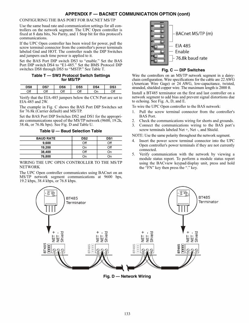
133
CONFIGURING THE BAS PORT FOR BACNET MS/TPUse the same baud rate and communication settings for all con-trollers on the network segment. The UPC Open controller isfixed at 8 data bits, No Parity, and 1 Stop bit for this protocol'scommunications.If the UPC Open controller has been wired for power, pull thescrew terminal connector from the controller's power terminalslabeled Gnd and HOT. The controller reads the DIP Switchesand jumpers each time power is applied to it.Set the BAS Port DIP switch DS3 to “enable.” Set the BASPort DIP switch DS4 to “E1-485.” Set the BMS Protocol DIPswitches DS8 through DS5 to “MSTP.” See Table T.
Table T — SW3 Protocol Switch Settingsfor MS/TP
Verify that the EIA-485 jumpers below the CCN Port are set toEIA-485 and 2W.The example in Fig. C shows the BAS Port DIP Switches setfor 76.8k (Carrier default) and MS/TP.Set the BAS Port DIP Switches DS2 and DS1 for the appropri-ate communications speed of the MS/TP network (9600, 19.2k,38.4k, or 76.8k bps). See Fig. D and Table U.
Table U — Baud Selection Table
WIRING THE UPC OPEN CONTROLLER TO THE MS/TPNETWORKThe UPC Open controller communicates using BACnet on anMS/TP network segment communications at 9600 bps,19.2 kbps, 38.4 kbps, or 76.8 kbps.
Fig. C — DIP SwitchesWire the controllers on an MS/TP network segment in a daisy-chain configuration. Wire specifications for the cable are 22 AWG(American Wire Gage) or 24 AWG, low-capacitance, twisted,stranded, shielded copper wire. The maximum length is 2000 ft.Install a BT485 terminator on the first and last controller on anetwork segment to add bias and prevent signal distortions dueto echoing. See Fig. A, D, and E.To wire the UPC Open controller to the BAS network:1. Pull the screw terminal connector from the controller's
BAS Port.2. Check the communications wiring for shorts and grounds.3. Connect the communications wiring to the BAS port’s
screw terminals labeled Net +, Net -, and Shield.NOTE: Use the same polarity throughout the network segment.4. Insert the power screw terminal connector into the UPC
Open controller's power terminals if they are not currentlyconnected.
5. Verify communication with the network by viewing amodule status report. To perform a module status reportusing the BACview keypad/display unit, press and holdthe “FN” key then press the “.” key.
Fig. D — Network Wiring
DS8 DS7 DS6 DS5 DS4 DS3Off Off Off Off On Off
BAUD RATE DS2 DS1 9,600 Off Off19,200 On Off38,400 Off On76,800 On On
APPENDIX F — BACNET COMMUNICATION OPTION (cont)

134
Fig. E — BT485 Terminator InstallationTo install a BT485 terminator, push the BT485 terminator on tothe BT485 connector located near the BACnet connector.NOTE: The BT485 terminator has no polarity associated with it.To order a BT485 terminator, consult Commercial Products i-Vu®
Open Control System Master Prices.
MS/TP WIRING RECOMMENDATIONS Recommendations are shown in Tables V and W. The wirejacket and UL temperature rating specifications list two accept-able alternatives. The Halar specification has a higher tempera-ture rating and a tougher outer jacket than the SmokeGardspecification, and it is appropriate for use in applications wherethe user is concerned about abrasion. The Halar jacket is alsoless likely to crack in extremely low temperatures. NOTE: Use the specified type of wire and cable for maximum sig-nal integrity.
Table V — MS/TP Wiring Recommendations
LEGEND
SPECIFICATION RECOMMMENDATIONCable Single twisted pair, low capacitance, CL2P, 22 AWG (7x30), TC foam FEP, plenum rated cable
Conductor 22 or 24 AWG stranded copper (tin plated) Insulation Foamed FEP 0.015 in. (0.381 mm) wall 0.060 in. (1.524 mm) O.D.
Color Code Black/White Twist Lay 2 in. (50.8 mm) lay on pair 6 twists/foot (20 twists/meter) nominal Shielding Aluminum/Mylar shield with 24 AWG TC drain wire
Jacket SmokeGard Jacket (SmokeGard PVC) 0.021 in. (0.5334 mm) wall 0.175 in. (4.445 mm) O.D. Halar Jacket (E-CTFE) 0.010 in. (0.254 mm) wall 0.144 in. (3.6576 mm) O.D.
DC Resistance 15.2 Ohms/1000 feet (50 Ohms/km) nominal Capacitance 12.5 pF/ft (41 pF/meter) nominal conductor to conductor
Characteristic Impedance 100 Ohms nominal Weight 12 lb/1000 feet (17.9 kg/km)
UL Temperature Rating SmokeGard 167°F (75°C) Halar -40 to 302°F (–40 to 150°C)
Voltage 300 Vac, power limited Listing UL: NEC CL2P, or better
AWG — American Wire GageCL2P — Class 2 Plenum CableDC — Direct CurrentFEP — Fluorinated Ethylene PolymerNEC — National Electrical CodeO.D. — Outside DiameterTC — Tinned CopperUL — Underwriters Laboratories
APPENDIX F — BACNET COMMUNICATION OPTION (cont)

135
Table W — Open System Wiring Specifications and Recommended Vendors
LEGEND
LOCAL ACCESS TO THE UPC OPEN CONTROLLERThe user can use a BACview6 handheld keypad display unit orthe Virtual BACview software as a local user interface to anOpen controller. These items let the user access the controllernetwork information. These are accessory items and do notcome with the UPC Open controller.The BACview6 unit connects to the local access port on theUPC Open controller. See Fig. F. The BACview software mustbe running on a laptop computer that is connected to the localaccess port on the UPC Open controller. The laptop will re-quire an additional USB link cable for connection.See the BACview Installation and User Guide for instructionson connecting and using the BACview6 device.To order a BACview6 Handheld (BV6H), consult CommercialProducts i-Vu® Open Control System Master Prices.
CONFIGURING THE UPC OPEN CONTROLLER’SPROPERTIES The UPC Open device and ComfortLink control must be set tothe same CCN Address (Element) number and CCN Bus num-ber. The factory default settings for CCN Element and CCNBus number are 1 and 0 respectively.If modifications to the default Element and Bus number are re-quired, both the ComfortLink and UPC Open configurationsmust be changed.The following configurations are used to set the CCN Addressand Bus number in the ComfortLink control. These configura-tions can be changed using the scrolling marquee display or ac-cessory Navigator handheld device.
Configuration→CCN→CCN.A (CCN Address)Configuration→CCN→CCN.B (CCN Bus Number)
The following configurations are used to set the CCN Addressand Bus Number in the UPC Open controller. These configura-tions can be changed using the accessory BACview6 display.Navigation: BACview→CCN Home: Element Comm Stat Element: 1 Bus: 0
Fig. F — BACview6 Device Connection
WIRING SPECIFICATIONS RECOMMENDED VENDORS AND PART NUMBERS
Wire Type Description Connect AirInternational Belden RMCORP Contractors
Wire and Cable
MS/TPNetwork (RS-485)
22 AWG, single twisted shielded pair, low capacitance, CL2P, TC foam FEP, plenum rated. See MS/TP Installation Guide for specifications.
W221P-22227 — 25160PV CLP0520LC
24 AWG, single twisted shielded pair, low capacitance, CL2P, TC foam FEP, plenum rated. See MS/TP Installation Guidefor specifications.
W241P-2000F 82841 25120-OR —
Rnet 4 conductor, unshielded, CMP, 18 AWG, plenum rated. W184C-2099BLB 6302UE 21450 CLP0442
AWG — American Wire GageCL2P — Class 2 Plenum CableCMP — Communications Plenum RatedFEP — Fluorinated Ethylene PolymerTC — Tinned Copper
APPENDIX F — BACNET COMMUNICATION OPTION (cont)

136
If the UPC Open is used with the chiller application of Lead/Lag/Standby, all chillers and UPC Open’s CCN element num-bers must be changed to a unique number in order to followCCN specifications. In this application, there can only be amaximum of 3 UPC Open controllers on a CCN bus.For the CCN Alarm Acknowledger configuration, the UPCOpen defaults to CCN Acknowledger. If a Chiller Lead/Lag/Standby application is being used, then the Carrier technicianmust change the configuration to only one CCN Acknowledgeron the CCN bus.For the CCN Time Broadcaster configuration, the UPC Opendefaults to CCN Time Broadcaster. If the Chiller Lead/Lag/Standby application is used, then the Carrier technician mustchange the configuration to only one CCN Time Broadcasteron the CCN bus.TROUBLESHOOTING If there are problems wiring or addressing the UPC Open con-troller, contact Carrier Technical Support.
COMMUNICATION LEDSThe LEDs indicate if the controller is communicating with thedevices on the network. See Tables X and Y. The LEDs shouldreflect communication traffic based on the baud rate set. Thehigher the baud rate the more solid the LEDs become. SeeFig. A for location of LEDs on UPC Open module.REPLACING THE UPC OPEN BATTERY The UPC Open controller’s 10-year lithium CR2032 batteryprovides a minimum of 10,000 hours of data retention duringpower outages.
Remove the battery from the controller, making note of the bat-tery's polarity. Insert the new battery, matching the battery's po-larity with the polarity indicated on the UPC Open controller.NETWORK POINTS LISTThe points list for the controller is shown in Table Z.
Table X — LED Status Indicators
Table Y — Run and Error LEDs Controller and Network Status Indication
IMPORTANT: Power must be ON to the UPC Open whenreplacing the battery, or the date, time, and trend data willbe lost.
LED STATUS
Power Lights when power is being supplied to the controller. The UPC Open controller is protected by internal solid-state polyswitches on the incoming power and network connections. These polyswitches are not replaceable and will reset themselves if the condition that caused the fault returns to normal.
Rx Lights when the controller receives data from the network segment; there is an Rx LED for Ports 1 and 2. Tx Lights when the controller transmits data to the network segment; there is a Tx LED for Ports 1 and 2.
Run Lights based on controller status. See Table Y. Error Lights based on controller status. See Table Y.
RUN LED ERROR LED STATUS2 flashes per second Off Normal 2 flashes per second 2 flashes, alternating with Run LED Five minute auto-restart delay after system error 2 flashes per second 3 flashes, then off Controller has just been formatted 2 flashes per second 1 flash per second Controller is alone on the network 2 flashes per second On Exec halted after frequent system errors or control programs halted 5 flashes per second On Exec start-up aborted, Boot is running 5 flashes per second Off Firmware transfer in progress, Boot is running 7 flashes per second 7 flashes per second, alternating with Run LED Ten second recovery period after brownout 14 flashes per second 14 flashes per second, alternating with Run LED Brownout
APPENDIX F — BACNET COMMUNICATION OPTION (cont)

137
Table Z — Network Points List
POINT DESCRIPTION CCN POINT NAME
READ/WRITE UNITS DEFAULT
VALUE RANGE BACNETOBJECT ID
BACNETOBJECT NAME
Active Demand Limit Val DEM_LIM R/W % N/A 0-100 AV:1 dem_lim_1Air Cond Entering Valv A hr_ea_a R N/A N/A On/Off BV:4 hr_ea_a_1Air Cond Entering Valv B hr_ea_b R N/A N/A On/Off BV:5 hr_ea_b_1Air Cond Leaving Valve A hr_la_a R N/A N/A On/Off BV:6 hr_la_a_1Air Cond Leaving Valve B hr_la_b R N/A N/A On/Off BV:7 hr_la_b_1Alarm Relay Status ALARMOUT R N/A N/A On/Off BV:8 alarmout_1
Alarm State ALM R N/A N/A0=Normal,1=Partial,
2=ShutdownAV:2 alm_1
Alert Relay Status ALERT R N/A N/A On/Off BV:9 alert_1Auto Changeover Active Mode_12 R N/A N/A Yes/No BV:10 mode_12_1Boiler Active Mode_17 R N/A N/A Yes/No BV:11 mode_17_1Boiler Command BOILER R N/A N/A On/Off BV:12 boiler_1CCN Chiller Start/Stop CHIL_S_S R/W N/A N/A Enable/Disable BV:1500 chil_s_s_1Chiller Capacity Signal CAPT_010 R volts N/A ±nn.n AV:3 capt_010_1Chiller Occupied? CHIL_OCC R N/A N/A Yes/No BV:1501 chil_occ_1CHWS Temperature - Prime Variable CHWSTEMP R °F N/A ±nnn.n AV:1612 chwstemp_1Cir A Compressor 1 Heater Out cp_a1_ht R N/A N/A On/Off BV:13 cp_a1_ht_1Cir A Compressor 1 Output CP_A1 R N/A N/A On/Off BV:14 cp_a1_1Cir A Compressor 2 Heater Out cp_a2_ht R N/A N/A On/Off BV:15 cp_a2_ht_1Cir A Compressor 2 Output CP_A2 R N/A N/A On/Off BV:16 cp_a2_1Cir A Compressor 3 Heater Out cp_a3_ht R N/A N/A On/Off BV:17 cp_a3_ht_1Cir A Compressor 3 Output CP_A3 R N/A N/A On/Off BV:18 cp_a3_1Cir A Compressor 4 Heater Out cp_a4_ht R N/A N/A On/Off BV:19 cp_a4_ht_1Cir A Compressor 4 Output CP_A4 R N/A N/A On/Off BV:20 cp_a4_1Cir A Crank Heater Current Cp1 cpa1_cur R amps N/A nnn.n AV:4 cpa1_cur_1Cir A Crank Heater Current Cp2 cpa2_cur R amps N/A nnn.n AV:5 cpa2_cur_1Cir A Crank Heater Current Cp3 cpa3_cur R amps N/A nnn.n AV:6 cpa3_cur_1Cir A Crank Heater Current Cp4 cpa4_cur R amps N/A nnn.n AV:7 cpa4_cur_1Cir A Discharge Pressure DP_A R psi N/A nnn.n AV:1601 dp_a_1Cir A EXV Position EXV_A R % N/A 0-100 AV:8 exv_a_1Cir A Fan Output DO # 1 fan_a1 R N/A N/A On/Off BV:21 fan_a1_1Cir A Fan Output DO # 2 fan_a2 R N/A N/A On/Off BV:22 fan_a2_1Cir A Fan Output DO # 3 fan_a3 R N/A N/A On/Off BV:23 fan_a3_1Cir A Fan Output DO # 4 fan_a4 R N/A N/A On/Off BV:24 fan_a4_1Cir A Fan Output DO # 5 fan_a5 R N/A N/A On/Off BV:25 fan_a5_1Cir A Fan Output DO # 6 fan_a6 R N/A N/A On/Off BV:26 fan_a6_1Cir A Fan Staging Number FAN_ST_A R N/A N/A 0-6 AV:9 fan_st_a_1Cir A Head Press Actuator Pos hd_pos_a R % N/A 0-100 AV:10 hd_pos_a_1Cir A Hot Gas Bypass Output HGBP_V_A R N/A N/A On/Off BV:27 hgbp_v_a_1Cir A Motor Thermistor Comp 1 cpa1_tmp R ohms N/A nnnn AV:11 cpa1_tmp_1Cir A Motor Thermistor Comp 2 cpa2_tmp R ohms N/A nnnn AV:12 cpa2_tmp_1Cir A Motor Thermistor Comp 3 cpa3_tmp R ohms N/A nnnn AV:13 cpa3_tmp_1Cir A Motor Thermistor Comp 4 cpa4_tmp R ohms N/A nnnn AV:14 cpa4_tmp_1Cir A Percent Total Capacity CAPA_T R % N/A 0-100 AV:15 capa_t_1Cir A Saturated Condensing Tmp SCT_A R °F N/A ±nnn.n AV:1602 sct_a_1Cir A Saturated Suction Temp SST_A R °F N/A ±nnn.n AV:1603 sst_a_1Cir A Suction Gas Temperature SUCT_T_A R °F N/A ±nnn.n AV:16 suct_t_a_1Cir A Suction Pressure SP_A R psi N/A ±nnn.n AV:1600 sp_a_1Cir A Suction Superheat Temp SH_A R ^F N/A ±nnn.n AV:17 sh_a_1Cir B Compressor 1 Heater Out cp_b1_ht R N/A N/A On/Off BV:28 cp_b1_ht_1Cir B Compressor 1 Output CP_B1 R N/A N/A On/Off BV:29 cp_b1_1Cir B Compressor 2 Heater Out cp_b2_ht R N/A N/A On/Off BV:30 cp_b2_ht_1Cir B Compressor 2 Output CP_B2 R N/A N/A On/Off BV:31 cp_b2_1Cir B Compressor 3 Heater Out cp_b3_ht R N/A N/A On/Off BV:32 cp_b3_ht_1Cir B Compressor 3 Output CP_B3 R N/A N/A On/Off BV:33 cp_b3_1Cir B Compressor 4 Heater Out cp_b4_ht R N/A N/A On/Off BV:34 cp_b4_ht_1Cir B Compressor 4 Output CP_B4 R N/A N/A On/Off BV:35 cp_b4_1Cir B Crank Heater Current Cp1 cpb1_cur R amps N/A nnn.n AV:18 cpb1_cur_1Cir B Crank Heater Current Cp2 cpb2_cur R amps N/A nnn.n AV:19 cpb2_cur_1Cir B Crank Heater Current Cp3 cpb3_cur R amps N/A nnn.n AV:20 cpb3_cur_1
APPENDIX F — BACNET COMMUNICATION OPTION (cont)
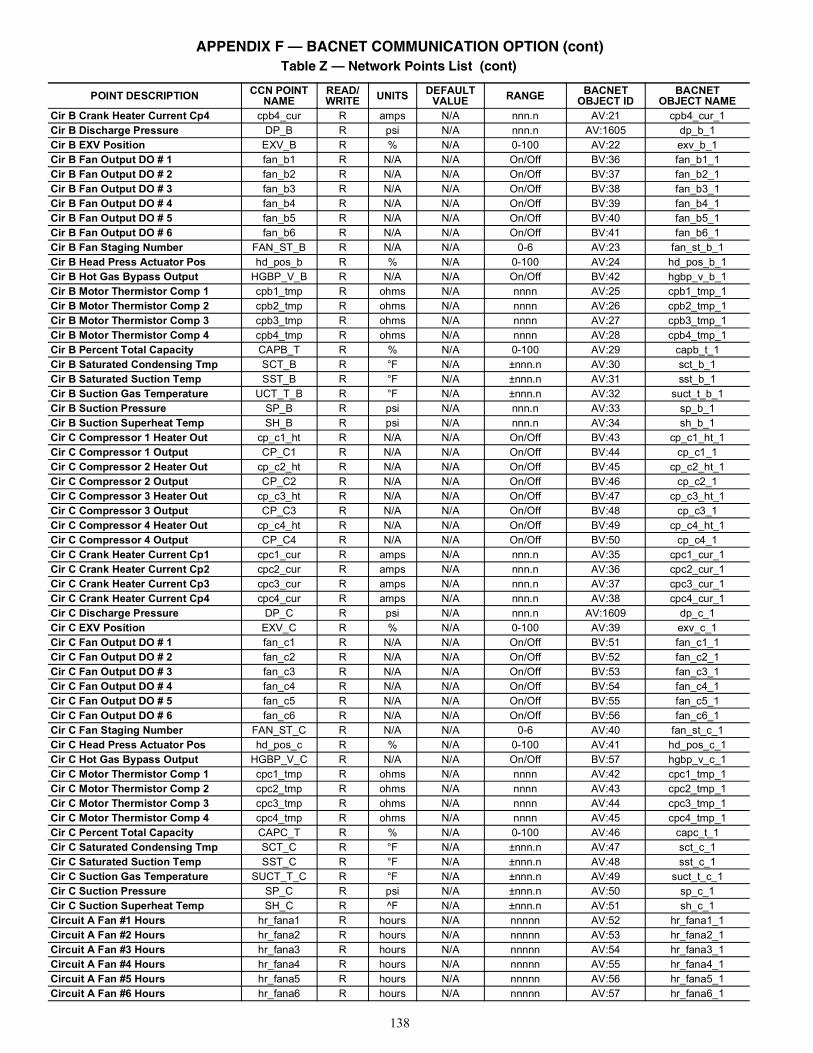
138
Cir B Crank Heater Current Cp4 cpb4_cur R amps N/A nnn.n AV:21 cpb4_cur_1Cir B Discharge Pressure DP_B R psi N/A nnn.n AV:1605 dp_b_1Cir B EXV Position EXV_B R % N/A 0-100 AV:22 exv_b_1Cir B Fan Output DO # 1 fan_b1 R N/A N/A On/Off BV:36 fan_b1_1Cir B Fan Output DO # 2 fan_b2 R N/A N/A On/Off BV:37 fan_b2_1Cir B Fan Output DO # 3 fan_b3 R N/A N/A On/Off BV:38 fan_b3_1Cir B Fan Output DO # 4 fan_b4 R N/A N/A On/Off BV:39 fan_b4_1Cir B Fan Output DO # 5 fan_b5 R N/A N/A On/Off BV:40 fan_b5_1Cir B Fan Output DO # 6 fan_b6 R N/A N/A On/Off BV:41 fan_b6_1Cir B Fan Staging Number FAN_ST_B R N/A N/A 0-6 AV:23 fan_st_b_1Cir B Head Press Actuator Pos hd_pos_b R % N/A 0-100 AV:24 hd_pos_b_1Cir B Hot Gas Bypass Output HGBP_V_B R N/A N/A On/Off BV:42 hgbp_v_b_1Cir B Motor Thermistor Comp 1 cpb1_tmp R ohms N/A nnnn AV:25 cpb1_tmp_1Cir B Motor Thermistor Comp 2 cpb2_tmp R ohms N/A nnnn AV:26 cpb2_tmp_1Cir B Motor Thermistor Comp 3 cpb3_tmp R ohms N/A nnnn AV:27 cpb3_tmp_1Cir B Motor Thermistor Comp 4 cpb4_tmp R ohms N/A nnnn AV:28 cpb4_tmp_1Cir B Percent Total Capacity CAPB_T R % N/A 0-100 AV:29 capb_t_1Cir B Saturated Condensing Tmp SCT_B R °F N/A ±nnn.n AV:30 sct_b_1Cir B Saturated Suction Temp SST_B R °F N/A ±nnn.n AV:31 sst_b_1Cir B Suction Gas Temperature UCT_T_B R °F N/A ±nnn.n AV:32 suct_t_b_1Cir B Suction Pressure SP_B R psi N/A nnn.n AV:33 sp_b_1Cir B Suction Superheat Temp SH_B R psi N/A nnn.n AV:34 sh_b_1Cir C Compressor 1 Heater Out cp_c1_ht R N/A N/A On/Off BV:43 cp_c1_ht_1Cir C Compressor 1 Output CP_C1 R N/A N/A On/Off BV:44 cp_c1_1Cir C Compressor 2 Heater Out cp_c2_ht R N/A N/A On/Off BV:45 cp_c2_ht_1Cir C Compressor 2 Output CP_C2 R N/A N/A On/Off BV:46 cp_c2_1Cir C Compressor 3 Heater Out cp_c3_ht R N/A N/A On/Off BV:47 cp_c3_ht_1Cir C Compressor 3 Output CP_C3 R N/A N/A On/Off BV:48 cp_c3_1Cir C Compressor 4 Heater Out cp_c4_ht R N/A N/A On/Off BV:49 cp_c4_ht_1Cir C Compressor 4 Output CP_C4 R N/A N/A On/Off BV:50 cp_c4_1Cir C Crank Heater Current Cp1 cpc1_cur R amps N/A nnn.n AV:35 cpc1_cur_1Cir C Crank Heater Current Cp2 cpc2_cur R amps N/A nnn.n AV:36 cpc2_cur_1Cir C Crank Heater Current Cp3 cpc3_cur R amps N/A nnn.n AV:37 cpc3_cur_1Cir C Crank Heater Current Cp4 cpc4_cur R amps N/A nnn.n AV:38 cpc4_cur_1Cir C Discharge Pressure DP_C R psi N/A nnn.n AV:1609 dp_c_1Cir C EXV Position EXV_C R % N/A 0-100 AV:39 exv_c_1Cir C Fan Output DO # 1 fan_c1 R N/A N/A On/Off BV:51 fan_c1_1Cir C Fan Output DO # 2 fan_c2 R N/A N/A On/Off BV:52 fan_c2_1Cir C Fan Output DO # 3 fan_c3 R N/A N/A On/Off BV:53 fan_c3_1Cir C Fan Output DO # 4 fan_c4 R N/A N/A On/Off BV:54 fan_c4_1Cir C Fan Output DO # 5 fan_c5 R N/A N/A On/Off BV:55 fan_c5_1Cir C Fan Output DO # 6 fan_c6 R N/A N/A On/Off BV:56 fan_c6_1Cir C Fan Staging Number FAN_ST_C R N/A N/A 0-6 AV:40 fan_st_c_1Cir C Head Press Actuator Pos hd_pos_c R % N/A 0-100 AV:41 hd_pos_c_1Cir C Hot Gas Bypass Output HGBP_V_C R N/A N/A On/Off BV:57 hgbp_v_c_1Cir C Motor Thermistor Comp 1 cpc1_tmp R ohms N/A nnnn AV:42 cpc1_tmp_1Cir C Motor Thermistor Comp 2 cpc2_tmp R ohms N/A nnnn AV:43 cpc2_tmp_1Cir C Motor Thermistor Comp 3 cpc3_tmp R ohms N/A nnnn AV:44 cpc3_tmp_1Cir C Motor Thermistor Comp 4 cpc4_tmp R ohms N/A nnnn AV:45 cpc4_tmp_1Cir C Percent Total Capacity CAPC_T R % N/A 0-100 AV:46 capc_t_1Cir C Saturated Condensing Tmp SCT_C R °F N/A ±nnn.n AV:47 sct_c_1Cir C Saturated Suction Temp SST_C R °F N/A ±nnn.n AV:48 sst_c_1Cir C Suction Gas Temperature SUCT_T_C R °F N/A ±nnn.n AV:49 suct_t_c_1Cir C Suction Pressure SP_C R psi N/A ±nnn.n AV:50 sp_c_1Cir C Suction Superheat Temp SH_C R ^F N/A ±nnn.n AV:51 sh_c_1Circuit A Fan #1 Hours hr_fana1 R hours N/A nnnnn AV:52 hr_fana1_1Circuit A Fan #2 Hours hr_fana2 R hours N/A nnnnn AV:53 hr_fana2_1Circuit A Fan #3 Hours hr_fana3 R hours N/A nnnnn AV:54 hr_fana3_1Circuit A Fan #4 Hours hr_fana4 R hours N/A nnnnn AV:55 hr_fana4_1Circuit A Fan #5 Hours hr_fana5 R hours N/A nnnnn AV:56 hr_fana5_1Circuit A Fan #6 Hours hr_fana6 R hours N/A nnnnn AV:57 hr_fana6_1
Table Z — Network Points List (cont)
POINT DESCRIPTION CCN POINT NAME
READ/WRITE UNITS DEFAULT
VALUE RANGE BACNETOBJECT ID
BACNETOBJECT NAME
APPENDIX F — BACNET COMMUNICATION OPTION (cont)

139
Circuit B Fan #1 Hours hr_fanb1 R hours N/A nnnnn AV:58 hr_fanb1_1Circuit B Fan #2 Hours hr_fanb2 R hours N/A nnnnn AV:59 hr_fanb2_1Circuit B Fan #3 Hours hr_fanb3 R hours N/A nnnnn AV:60 hr_fanb3_1Circuit B Fan #4 Hours hr_fanb4 R hours N/A nnnnn AV:61 hr_fanb4_1Circuit B Fan #5 Hours hr_fanb5 R hours N/A nnnnn AV:62 hr_fanb5_1Circuit B Fan #6 Hours hr_fanb6 R hours N/A nnnnn AV:63 hr_fanb6_1Circuit C Fan #1 Hours hr_fanc1 R hours N/A nnnnn AV:64 hr_fanc1_1Circuit C Fan #2 Hours hr_fanc2 R hours N/A nnnnn AV:65 hr_fanc2_1Circuit C Fan #3 Hours hr_fanc3 R hours N/A nnnnn AV:66 hr_fanc3_1Circuit C Fan #4 Hours hr_fanc4 R hours N/A nnnnn AV:67 hr_fanc4_1Circuit C Fan #5 Hours hr_fanc5 R hours N/A nnnnn AV:68 hr_fanc5_1Circuit C Fan #6 Hours hr_fanc6 R hours N/A nnnnn AV:69 hr_fanc6_1
Circuit Loading Sequence lead_cir R/W N/A 00=Auto
1=A Lead2=B Lead3=C Lead
AV:70 lead_cir_1
Compressor A1 Hours HR_CP_A1 R hours N/A nnnnn AV:71 hr_cp_a1_1Compressor A1 Starts st_cp_a1 R N/A N/A nnnnn AV:72 st_cp_a1_1Compressor A2 Hours HR_CP_A2 R hours N/A nnnnn AV:73 hr_cp_a2_1Compressor A2 Starts st_cp_a2 R N/A N/A nnnnn AV:74 st_cp_a2_1Compressor A3 Hours HR_CP_A3 R hours N/A nnnnn AV:75 hr_cp_a3_1Compressor A3 Starts st_cp_a3 R N/A N/A nnnnn AV:76 st_cp_a3_1Compressor A4 Hours HR_CP_A4 R hours N/A nnnnn AV:77 hr_cp_a4_1Compressor A4 Starts st_cp_a4 R N/A N/A nnnnn AV:78 st_cp_a4_1Compressor B1 Hours HR_CP_B1 R hours N/A nnnnn AV:79 hr_cp_b1_1Compressor B1 Starts st_cp_b1 R N/A N/A nnnnn AV:80 st_cp_b1_1Compressor B2 Hours HR_CP_B2 R hours N/A nnnnn AV:81 hr_cp_b2_1Compressor B2 Starts st_cp_b2 R N/A N/A nnnnn AV:82 st_cp_b2_1Compressor B3 Hours HR_CP_B3 R hours N/A nnnnn AV:83 hr_cp_b3_1Compressor B3 Starts st_cp_b3 R N/A N/A nnnnn AV:84 st_cp_b3_1Compressor B4 Hours HR_CP_B4 R hours N/A nnnnn AV:85 hr_cp_b4_1Compressor B4 Starts st_cp_b4 R N/A N/A nnnnn AV:86 st_cp_b4_1Compressor C1 Hours HR_CP_C1 R hours N/A nnnnn AV:87 hr_cp_c1_1Compressor C1 Starts st_cp_c1 R N/A N/A nnnnn AV:88 st_cp_c1_1Compressor C2 Hours HR_CP_C2 R hours N/A nnnnn AV:89 hr_cp_c2_1Compressor C2 Starts st_cp_c2 R N/A N/A nnnnn AV:90 st_cp_c2_1Compressor C3 Hours HR_CP_C3 R hours N/A nnnnn AV:91 hr_cp_c3_1Compressor C3 Starts st_cp_c3 R N/A N/A nnnnn AV:92 st_cp_c3_1Compressor C4 Hours HR_CP_C4 R hours N/A nnnnn AV:93 hr_cp_c4_1Compressor C4 Starts st_cp_c4 R N/A N/A nnnnn AV:94 st_cp_c4_1Control Point CTRL_PNT R/W °F N/A ±nnn.n AV:96 ctrl_pnt_1Controlled Water Temp CTRL_WT R °F N/A ±nnn.n AV:95 ctrl_wt_1
Cooler Fluid Type flui_typ R N/A 11=Water, 2=Brine
3=Low BrineAV:97 flui_typ_1
Cooler Heater Active Mode_06 R N/A N/A Yes/No BV:58 mode_06_1Cooler Heater Command COOLHEAT R N/A N/A On/Off BV:59 coolheat_1Cooler Pumps Rotation Mode_07 R N/A N/A Yes/No BV:60 mode_07_1
Cooler Pumps Sequence pump_seq R/W N/A 0
0=No pump,1=1 pump only,
2=2 pumps auto,
3=Pump 1 manual,
4=Pump 2 manual
AV:98 pump_seq_1
Cooling Ice Setpoint ice_sp R/W ^F 1 -20-+32 AV:99 ice_sp_1Cooling Ramp Loading cramp_sp R/W ^F 0 0.2-2.0 AV:100 cramp_sp_1Cooling Reset Deg. Value cr_deg R/W °F 44 -30 -+30 AV:101 cr_deg_1Cooling Setpoint 1 csp1 R/W °F 44 -20.0-+78.8 AV:102 csp1_1Cooling Setpoint 2 csp2 R/W min N/A -20.0-+78.8 AV:103 csp2_1Critical Alarm Status CRITICAL R N/A N/A On/Off BV:61 critical_1Current Full Reset Value v_cr_fu R/W ma 0 0-20 AV:104 v_cr_fu_1Current No Reset Value v_cr_no R/W ma 0 0-20 AV:105 v_cr_no_1
Table Z — Network Points List (cont)
POINT DESCRIPTION CCN POINT NAME
READ/WRITE UNITS DEFAULT
VALUE RANGE BACNETOBJECT ID
BACNETOBJECT NAME
APPENDIX F — BACNET COMMUNICATION OPTION (cont)

140
Current Setpoint SP R °F N/A ±nnn.n AV:3500 chws_sp_1Defrost Active On Cir A Mode_19 R N/A N/A Yes/No BV:62 mode_19_1Defrost Active On Cir B Mode_20 R N/A N/A Yes/No BV:63 mode_20_1Delta T Full Reset Value dt_cr_fu R/W ^F 0 0-25 AV:106 dt_cr_fu_1Delta T No Reset Value dt_cr_no R/W ^F 0 0-25 AV:107 dt_cr_no_1Demand Limit Active Mode_04 R N/A N/A Yes/No BV:64 mode_04_1
Demand Limit Type Select lim_sel R/W N/A 0
0=None,1=Switch control,
2=4-20mA Control
AV:108 lim_sel_1
Electric Heat Active Mode_15 R N/A N/A 0-4/Off BV:67 mode_15_1Electrical Box Safety ELEC_BOX R N/A N/A Yes/No BV:65 elec_box_1Electrical Heat Stage EHS_STEP R N/A N/A Open/Close BV:66 ehs_step_1Element Comm Status R N/A N/A BV:2999 element_stat_1Emergency Stop EMSTOP R/W N/A N/A Enable/Disable BV:68 emstop_1Equipment Alarm R N/A N/A BV:146 element_alarm_1External Temperature OAT R °F N/A ±nnn.n AV:109 oat_1Flow Checked if Pump Off pump_loc R/W N/A Yes Yes/No BV:69 pump_loc_1Free Cooling Active Mode_13 R N/A N/A Yes/No BV:70 mode_13_1Free Cooling Disable Sw. FC_SW R N/A N/A Yes/No BV:72 fc_sw_1Free Cooling Disable? FC_DSBLE R N/A N/A Yes/No BV:71 fc_dsble_1Heat Reclaim Pump Hours hr_hpump R hours N/A nnnnn AV:112 hr_hpump_1Heat Reclaim Select RECL_SEL R/W N/A N/A Yes/No BV:74 recl_sel_1
Heat/Cool Select HC_SEL R/W N/A N/A0=Cool, 1=Heat,2=Auto
AV:110 hc_sel_1
Heat/Cool Status HEATCOOL R N/A N/A0=Cool, 1=Heat
2=Stand-by, 3=Both
AV:111 heatcool_1
Heating Low EWT Lockout Mode_16 R N/A N/A Yes/No BV:73 mode_16_1High DGT Circuit A Mode_24 R N/A N/A Yes/No BV:75 mode_24_1High DGT Circuit B Mode_25 R N/A N/A Yes/No BV:76 mode_25_1High DGT Circuit C Mode_26 R N/A N/A Yes/No BV:77 mode_26_1High Pres Override Cir A Mode_27 R N/A N/A Yes/No BV:78 mode_27_1High Pres Override Cir B Mode_28 R N/A N/A Yes/No BV:79 mode_28_1High Pres Override Cir C Mode_29 R N/A N/A Yes/No BV:80 mode_29_1Ice Done Storage Switch ICE_SW R N/A N/A Open/Close BV:81 ice_sw_1Ice Mode in Effect Mode_18 R N/A N/A Yes/No BV:82 mode_18_1Interlock Status LOCK_1 R N/A N/A Open/Close BV:83 lock_1_1Lag Capacity Limit Value LAG_LIM R % N/A nnn AV:113 lag_lim_1Limit 4-20mA Signal LIM_ANAL R ma N/A ±nn.n AV:114 lim_anal_1Limit Switch 1 Status LIM_SW1 R N/A N/A Open/Close BV:84 lim_sw1_1Limit Switch 2 Status LIM_SW2 R N/A N/A Open/Close BV:85 lim_sw2_1Local Schedule R N/A N/A BV:2 schedule_1Low Suction Circuit A Mode_21 R N/A N/A Yes/No BV:86 mode_21_1Low Suction Circuit B Mode_22 R N/A N/A Yes/No BV:87 mode_22_1Low Suction Circuit C Mode_23 R N/A N/A Yes/No BV:88 mode_23_1mA For 0% Demand Limit lim_ze R/W mA 0 0-20 AV:117 lim_ze_1mA For 100% Demand Limit lim_mx R/W mA 0 0-20 AV:118 lim_mx_1Machine Operating Hours HR_MACH R hours N/A nnnnn AV:115 hr_mach_1Machine Starts Number st_mach R N/A N/A nnnnn AV:116 st_mach_1
Master/Slave Select ms_sel R/W N/A 00= Disable,1=Master,2=Slave
AV:119 ms_sel_1
Minutes Left for Start min_left R min N/A 0-15 AV:120 min_left_1Night Low Noise Active Mode_09 R N/A N/A Yes/No BV:89 mode_09_1OAT Full Reset Value oatcr_fu R/W °F 14 14-125 AV:121 oatcr_fu_1OAT No Reset Value oatcr_no R/W °F 0 0-25 AV:122 oatcr_no_1Occupied Override Switch OCC_OVSW R N/A N/A Open/Close BV:90 occ_ovsw_1On/Off - Remote Switch ONOFF_SW R N/A N/A Open/Close BV:91 onoff_sw_1Optional Space Temp SPACETMP R °F N/A ±nnn.n AV:123 spacetmp_1Pass For All User Config all_pass R/W N/A No No/Yes BV:92 all_pass_1Percent Total Capacity CAP_T R % N/A nnn AV:1700 cap_t_1
Table Z — Network Points List (cont)
POINT DESCRIPTION CCN POINT NAME
READ/WRITE UNITS DEFAULT
VALUE RANGE BACNETOBJECT ID
BACNETOBJECT NAME
APPENDIX F — BACNET COMMUNICATION OPTION (cont)

141
Pump Auto Rotation Delay pump_del R/W hours 48 24-3000 AV:124 pump_del_1Pump Periodic Start Mode_08 R N/A N/A Yes/No BV:93 mode_08_1Pump Run Status PUMP_DEF R N/A N/A Open/Close BV:94 pump_def_1Pump Sticking Protection pump_per R/W N/A No No/Yes BV:95 pump_per_1Pumpdown Pressure Cir A PD_P_A R psi N/A ±nnn.n AV:125 pd_p_a_1Pumpdown Pressure Cir B PD_P_B R psi N/A ±nnn.n AV:126 pd_p_b_1Pumpdown Saturated Tmp A hr_sat_a R °F N/A n AV:127 hr_sat_a_1Pumpdown Saturated Tmp B hr_sat_b R °F N/A n AV:128 hr_sat_b_1Ramp Loading Active Mode_05 R N/A N/A Yes/No BV:96 mode_05_1Ramp Loading Select ramp_sel R/W N/A No No/Yes BV:97 ramp_sel_1Ready or Running Status READY R N/A N/A On/Off BV:98 ready_1Reclaim Active Mode_14 R N/A N/A Yes/No BV:99 mode_14_1Reclaim Condenser Flow condflow R N/A N/A On/Off BV:100 condflow_1Reclaim Condenser Heater cond_htr R N/A N/A On/Off BV:101 cond_htr_1Reclaim Condenser Pump CONDPUMP R N/A N/A On/Off BV:102 condpump_1Reclaim Condenser Pump COND_PMP R N/A N/A On/Off BV:103 cond_pmp_1Reclaim Deadband hr_deadb R/W ^F 9.0 5-27 AV:129 hr_deadb_1Reclaim Entering Fluid HR_EWT R °F N/A ±nnn.n AV:130 hr_ewt_1Reclaim Leaving Fluid HR_LWT R °F N/A ±nnn.n AV:131 hr_lwt_1Reclaim Setpoint rsp R/W °F 122 95-122 AV:132 rsp_1Reclaim Status Circuit A hrstat_a R N/A N/A n AV:133 hrstat_a_1Reclaim Status Circuit B hrstat_b R N/A N/A n AV:134 hrstat_b_1Reclaim Valve Position hr_v_pos R % N/A ±nnn.n AV:135 hr_v_pos_1Remote Heat/Cool Switch HC_SW R N/A N/A Open/Close BV:104 hc_sw_1Remote Interlock Status REM_LOCK R N/A N/A Open/Close BV:105 rem_lock_1Remote Reclaim Switch RECL_SW R N/A N/A Open/Close BV:106 recl_sw_1Remote Setpoint Switch SETP_SW R N/A N/A Open/Close BV:107 setp_sw_1Reset in Effect Mode_03 R N/A N/A Yes/No BV:108 mode_03_1Reset/Setpoint 4-20mA In SP_RESET R ma N/A ±nn.n AV:136 sp_reset_1Rotate Pumps Now? ROT_PUMP R/W N/A N/A Yes/No BV:109 rot_pump_1
Run Status STATUS R N/A N/A
0=Off, 1=Running
2=Stopping, 3= Delay
4=Tripout, 5=Ready
6=Override, 7=Defrost
8=Run Test, 9=Test
AV:137 status_1
Running Status RUNNING R N/A N/A On/Off BV:110 running_1Second Setpoint in Use Mode_02 R N/A N/A Yes/No BV:111 mode_02_1Setpoint Occupied? SP_OCC R N/A N/A Yes/No BV:112 sp_occ_1Shutdown Indicator State SHUTDOWN R N/A N/A On/Off BV:113 shutdown_1Space T Full Reset Value spacr_fu R °F 14 14-125 AV:138 spacr_fu_1Space T No Reset Value spacr_no R °F 14 14-125 AV:139 spacr_no_1Staged Loading Sequence seq_typ R/W N/A No No/Yes BV:114 seq_typ_1Starts Max During 1 Hour st_cp_mx R N/A N/A nnnnn AV:141 st_cp_mx_1Starts/hr From Last 24 h st_cp_av R N/A N/A nnnnn AV:140 st_cp_av_1Startup Delay in Effect Mode_01 R N/A N/A Yes/No BV:115 mode_01_1Sub Condenser Temp Cir A hr_subta R °F N/A ±nnn.n AV:142 hr_subta_1Sub Condenser Temp Cir B hr_subtb R °F N/A ±nnn.n AV:143 hr_subtb_1Subcooling Temperature A hr_subca R °F N/A ±nnn.n AV:144 hr_subca_1Subcooling Temperature B hr_subcb R °F N/A ±nnn.n AV:145 hr_subcb_1Superheat Override Cir A Mode_30 R N/A N/A Yes/No BV:116 mode_30_1Superheat Override Cir B Mode_31 R N/A N/A Yes/No BV:117 mode_31_1Superheat Override Cir C Mode_32 R N/A N/A Yes/No BV:118 mode_32_1Switch Limit Setpoint 1 lim_sp1 R/W % 100 0-100 AV:146 lim_sp1_1Switch Limit Setpoint 2 lim_sp2 R/W % 100 0-100 AV:147 lim_sp2_1Switch Limit Setpoint 3 lim_sp3 R/W % 100 0-100 AV:148 lim_sp3_1
System Cooling Demand Level R N/A N/A AV:9006 cool_demand_level_1
System Demand Limiting R N/A N/A BV:3 dem_lmt_act_1System Manager Active Mode_10 R N/A N/A Yes/No BV:119 mode_10_1
Table Z — Network Points List (cont)
POINT DESCRIPTION CCN POINT NAME
READ/WRITE UNITS DEFAULT
VALUE RANGE BACNETOBJECT ID
BACNETOBJECT NAME
APPENDIX F — BACNET COMMUNICATION OPTION (cont)

142
LEGEND
System OAT Master R N/A N/A AV:80001 mstr_oa_temp_1Unit Off to On Delay off_on_d R/W min 1 1-15 AV:149 off_on_d_1User Defined Analog 1 R N/A N/A AV:2901 user_analog_1_1User Defined Analog 2 R N/A N/A AV:2902 user_analog_2_1User Defined Analog 3 R N/A N/A AV:2903 user_analog_3_1User Defined Analog 4 R N/A N/A AV:2904 user_analog_4_1User Defined Analog 5 R N/A N/A AV:2905 user_analog_5_1User Defined Binary 1 R N/A N/A BV:2911 user_binary_1_1User Defined Binary 2 R N/A N/A BV:2912 user_binary_2_1User Defined Binary 3 R N/A N/A BV:2913 user_binary_3_1User Defined Binary 4 R N/A N/A BV:2914 user_binary_4_1User Defined Binary 5 R N/A N/A BV:2915 user_binary_5_1Water Cond Enter Valve A hr_ew_a R N/A N/A On/Off BV:120 hr_ew_a_1Water Cond Enter Valve B hr_ew_b R N/A N/A On/Off BV:121 hr_ew_b_1Water Cond Leaving Val A hr_lw_a R N/A N/A On/Off BV:122 hr_lw_a_1Water Cond Leaving Val B hr_lw_b R N/A N/A On/Off BV:123 hr_lw_b_1Water Exchanger Entering Temp EWT R °F N/A ±nnn.n AV:150 ewt_1Water Exchanger Leaving Temp LWT R °F N/A ±nnn.n AV:151 lwt_1Water Pump #1 Command CPUMP_1 R N/A N/A On/Off BV:124 cpump_1_1Water Pump #1 Hours hr_cpum1 R hours N/A nnnnn AV:152 hr_cpum1_1Water Pump #2 Command CPUMP_2 R N/A N/A On/Off BV:125 cpump_2_1Water Pump #2 Hours hr_cpum2 R hours N/A nnnnn AV:153 hr_cpum2_1
Table Z — Network Points List (cont)
POINT DESCRIPTION CCN POINT NAME
READ/WRITE UNITS DEFAULT
VALUE RANGE BACNETOBJECT ID
BACNETOBJECT NAME
CCN — Carrier Comfort NetworkCHWS — Chilled Water SetpointDGT — Discharge Gas TemperatureDO — Discrete OutputEWT — Entering Water TemperatureEXV — Electronic Expansion ValveOAT — Outdoor Air TemperatureR — ReadW — Write
APPENDIX F — BACNET COMMUNICATION OPTION (cont)

143
LOW AMBIENT TEMPERATURE HEAD PRESSURECONTROL OPERATING INSTRUCTIONSThe 30RB low ambient control is a variable frequency drive(VFD) that varies the speed of the lead condenser fan in eachcircuit to maintain the calculated head pressure control setpoint. The fan speed varies in proportion to the 0 to 10 vdc an-alog signal produced by the AUX1 fan board. The display indi-cates motor speed in Hz by default. These units may use a Sie-mens Micromaster 420/440 VFD or a Schneider Altivar 21 and212. The Schneider Altivar VFD performs the same functionsas Siemens drive. However, there are different control wiringconnections and parameter programming.Siemens VFD OperationThe low ambient temperature head pressure controller is pre-configured to operate from a 0 to 10 vdc analog input signalpresent on terminals 3 (AIN+) and 4 (AIN–). Jumpers betweenterminals 2 and 4 and terminals 5 and 8 are required for properoperation. The drive is enabled based on an increase in the ana-log input signal above 0 vdc. Output is varied from 0 Hz to 60Hz as the analog signal increases from 0 vdc to 10 vdc. Whenthe signal is at 0 vdc the drive holds the fan at 0 rpm. The headpressure control set point is not adjustable. The MBB deter-mines the control set point as required. Siemens VFD ReplacementIf the controller is replaced the parameters in Table AA mustbe configured. See Fig. G and H.
Table AA — Siemens VFD Head Pressure Control Parameters
*Remove jumper from terminals 5 and 8 (or terminals 5 and 9 for 575-vunits) before configuring parameter. Reinstall jumper after configurationis complete.
Fig. G — Low Ambient Temperature Control Power Wiring
Fig. H — Low Ambient Temperature Control Signal Wiring
DIP switch settings:• DIP switch 1 is not used.• DIP switch 2 is the motor frequency: OFF = 50 Hz,
ON = 60 Hz)Siemens VFD ProgrammingParameter values can be altered via the operator panel. The op-erator panel features a five-digit, seven-segment display fordisplaying parameter numbers and values, alarm and fault mes-sages, set points, and actual values. See Fig. I. See Table ABfor additional information on the operator panel.NOTE: The operator panel motor control functions are disabledby default. To control the motor via the operator panel, parame-ter P0700 should be set to 1 and P1000 set to 1. The operatorpanel can be fitted to and removed from the drive while power isapplied. If the operator panel has been set as the I/O control(P0700 = 1), the drive will stop if the operator panel is removed.
Fig. I — Siemens VFD Low AmbientTemperature Controller
PARAMETER* VALUE DESCRIPTIONP0010 1 Enter Quick CommissioningP0311 1140 Rated Motor SpeedP3900 1 End of Quick CommissioningP0003 3 User Access LevelP0757 0.50 Control Signal Scaling OffsetP0761 0.50 Control Signal Scaling OffsetP1210 6 Automatic Restart SettingP1310 10 Continuous Boost Parameter
T2
L3
L2
L 1
T3
W V
DC
DC
LL1
NL2
L3
+ -
U
T1 TO CONDENSER
FAN MOTOR
ON
1 2 3 4
98765
DIN1 DIN2 DIN3 24V+ 0V
AOUT+ AOUT- P+ N-
12 13 14 15
DIP SWITCH 2
RLB RLC
10 11
10V+ 0V AIN+ AIN-
– + 0-10 VDC FROM FAN BOARD
ENABLEJUMPER
NOTE: For 575-v units, jumper terminals are 5 and 9.
APPENDIX G — SIEMENS OR SCHNEIDER LOW AMBIENT DRIVES

144
Changing Single Digits in Parameter Values with the Siemens VFD Operator PanelTo change the parameters value rapidly, the single digits of the dis-play can be changed by performing the following actions:1. Press (parameter button) to enter the parameter value
changing level.
2. Press (function button) to cause the far right digit to blink.
3. Change the value of this digit by pressing or .
4. Press again to cause the next digit to blink.
5. Perform steps 2 to 4 until the required value is displayed.
6. Press to exit the parameter value changing level.NOTE: The function button may also be used to acknowledge afault condition.Quick Commissioning with the Siemens VFD Operator Panel It is important that parameter P0010 be used for commission-ing and P0003 be used to select the number of parameters to beaccessed. The P0010 parameter allows a group of parametersto be selected that will enable quick commissioning. Parame-ters such as motor settings and ramp settings are included. Atthe end of the quick commissioning sequences, P3900 shouldbe selected, which, when set to 1, will carry out the necessarymotor calculations and clear all other parameters (not included
in P0010=1) to the default settings. This will only occur inQuick Commissioning mode. See Fig. J.Reset the Siemens VFD to Factory DefaultTo reset all parameters to the factory default settings, the fol-lowing parameters should be set as follows:1. Set P0010=30.2. Set P0970 =1.NOTE: The reset process can take up to 3 minutes to complete.Troubleshooting the Siemens VFD with the Operating PanelWarnings and faults are displayed on the operating panel withAxxx and Fxxx. The individual messages are shown in Table AC.If the motor fails to start, check the following:• Power on T1, T2 and T3.• Configuration jumpers in place.• Control signal between 1 vdc and 10 vdc on terminals 3 and 4.• P0010 = 0.• P0700 = 2.
Siemens VFD Fault Messages (Tables AC and AD)In the event of a failure, the drive switches off and a fault codeappears on the display.NOTE: To reset the fault code, use one of the following methods:1. Cycle the power to the drive.
2. Press the button on the operator panel.
P
Fn
Fn
P
Fn
Table AB — Siemens VFD Low Ambient Temperature Controller Operator Panel
PANEL/BUTTON FUNCTION DESCRIPTION
Indicates Status The LCD displays the settings currently used by the converter.
Start Converter The Start Converter button is disabled by default. To enable this button set P0700 = 1.
Stop ConverterPress the Stop Converter button to cause the motor to come to a standstill at the selected ramp down rate. Disabled by default, to enable set P0700 = 1.Press the Stop Converter button twice (or hold) to cause the motor to coast to a standstill. This function is always enabled.
Change Direction Press the Change Direction button to change direction of rotation of the motor. Reverse is indicated by a minus (–) sign or a flashing decimal point. Disabled by default, to enable set P0700 = 1.
Jog MotorPress the Jog Motor button while the inverter has no output to cause the motor to start and run at the preset jog frequency. The motor stops when the button is released. The Jog Motor button is not enabled when the motor is running.
Functions
Use the Functions button to view additional information. Press and hold the button to display the following information starting from any parameter during operation:1. DC link voltage (indicated by d – units V).2. Output current. (A)3. Output frequency (Hz)4. Output voltage (indicated by o – units V).5. The value selected in P0005 (If P0005 is set to show any of the above [3, 4, or 5] then this will not be shown when toggling through the menu).Press the Functions button repeatedly to toggle through displayed values.
Jump FunctionPress of the Fn button from any parameter (rXXXX or PXXXX) to immediately jump to R0000, when another parameter can be changed, if required. Return to R0000 and press the Functions again to return.
Access Parameters Allows access to the parameters.
Increase Value Press the Increase Value button to increase the displayed value. To change the Frequency Setpoint using the operator panel set P1000 = 1.
Decrease Value Press the Decrease Value button to decrease the displayed value. To change the Frequency Setpoint using the operating panel set P1000 = 1.
0
jog
Fn
P
APPENDIX G — SIEMENS OR SCHNEIDER LOW AMBIENT DRIVES (cont)

145
Fig. J — Siemens VFD Low Ambient Temperature Controller Flow Chart Quick Commissioning
P0010 Start Quick Commissioning0 Ready to Run1 Quick Commissioning30 Factory SettingNOTE: P0010 must always be set back to ‘0’ before operating the motor. However if P3900 = 1 is set after commissioning this is done automatically.
P0100 Operation0 Power in kW; f default 50 Hz1 Power in hp; f default 60 Hz2 Power in kW; f default 60 HzNOTE: Settings 0 and 1 should be changed using the DIP switches to allow permanent setting.
P0304 Rated Motor Voltage*10 V — 2000 VNominal motor voltage (V) from rating plate
P0305 Rated Motor Current*0 — 2 x inverter rated current (A)Nominal motor current (A) from rating plate
P0307 Rated Motor Power*0 kW — 2000 kWNominal motor power (kW) from rating plate.If P0100 = 1, values will be in hp
P0310 Rated Motor Frequency*12 Hz — 650 HzNominal motor frequency (Hz) from rating plate
P0311 Rated Motor Speed*0 — 4000 1/minNominal motor speed (rpm) from rating plate
P0700 Selection of Command Source(on/off/reverse)0 Factory Setting1 Basic Operator Panel2 Terminal/Digital Inputs (default)
P1000 Selection of Frequency Setpoint0 No frequency setpoint1 Operator panel frequency control 2 Analog Setpoint (default)
P1080 Min. Motor FrequencySets minimum motor frequency (0-650Hz) at which the motor will run independent of the frequency setpoint. The value set here is valid for both clockwise and counterclockwise rotation.
P1082 Max. Motor FrequencySets maximum motor frequency (0-650Hz) at which the motor will run at independent of the frequency setpoint. The value set here is valid for both clockwise and counterclockwise rotation.
P1120 Ramp-Up Time0 s - 650 sTime taken for the motor to accelerate from standstill up to maximum motor frequency.
P1121 Ramp-Down Time0 s - 650 sTime taken for motor to decelerate from maximum motorfrequency down to a standstill.
P3900 End Quick Commissioning0 End Quick Commissioning without motor calculation or
factory reset.1 End Quick Commissioning with motor calculation and
factory reset (Recommended)2 End Quick Commissioning with motor calculation and with
I/O reset3 End Quick Commissioning with motor calculation but
without I/O reset*Motor-specific parameters — see motor rating plate.NOTE: Shaded boxes are for reference only.
APPENDIX G — SIEMENS OR SCHNEIDER LOW AMBIENT DRIVES (cont)

146
LEGENDI2t — Current Squared Time
Table AC — Siemens VFD Low Ambient Temperature Controller Fault Messages
FAULT POSSIBLE CAUSES TROUBLESHOOTING
F0001Overcurrent
• Motor power does not correspond to the inverter power
• Motor lead short circuit• Ground fault
Check the following:1. Motor power (P0307) must correspond to inverter power (P0206)2. Motor cable and motor must have no short-circuits or ground faults3. Motor parameters must match the motor in use4. Motor must not be obstructed or overloadedAfter Steps 1-4 have been checked, increase the ramp time (P1120) and reduce the boost level (P1310, P1311, P1312).
F0002Overvoltage
• DC-link voltage (r0026) exceeds trip level (P2172)
• Overvoltage can be caused either by too high main supply voltage or if motor is in regenera-tive mode
• Regenerative mode can be caused by fast ramp downs or if the motor is driven from an active load
Check the following:1. Supply voltage (P0210) must lie within limits indicated on rating plate2. DC-link voltage controller must be enabled (P1240) and have parameters set
correctly3. Ramp-down time (P1121) must match inertia of load
F0003Undervoltage
• Main supply failed• Shock load outside specified limits
Check the following:1. Supply voltage (P0210) must lie within limits indicated on rating plate2. Supply must not be susceptible to temporary failures or voltage reductions
F0004Drive
Overtemperature
• Ambient temperature outside of limits• Fan failure
Check the following:1. Fan must turn when inverter is running2. Pulse frequency must be set to default value3. Air inlet and outlet points are not obstructed4. Ambient temperature could be higher than specified for the drive.
F0005Drive I2t
• Drive overloaded• Duty cycle too demanding• Motor power (P0307) exceeds drive power
capability (P0206)
Check the following:1. Load duty cycle must lie within specified limits2. Motor power (P0307) must match drive power (P0206)
F0011Motor
Overtemperature I2t
• Motor overloaded• Motor data incorrect• Long time period operating at low speeds
1. Check motor data2. Check loading on motor3. Boost settings too high (P1310, P1311, P1312)4. Check parameter for motor thermal time constant5. Check parameter for motor I2t warning level
F0041Stator Resistance
Measurement Failure
Stator resistance measurement failure 1. Check if the motor is connected to the drive2. Check that the motor data has been entered correctly
F0051Parameter EEPROM Fault
Reading or writing of the non-volatile parameter storage has failed
1. Factory reset and new parameters set2. Replace drive
F0052Powerstack Fault
Reading of the powerstack information has failed or the data is invalid
Replace drive
F0060Asic Timeout
Internal communications failure 1. Acknowledge fault2. Replace drive if repeated
F0070Communications
Board Setpoint Error
No setpoint received from communications board during telegram off time
1. Check connections to the communications board2. Check the master
F0071No Data for USS (RS232
Link) DuringTelegram Off Time
No response during telegram off time via USS(BOP link)
1. Check connections to the communications board2. Check the master
F0072No Data from USS (RS485
Link) DuringTelegram Off Time
No response during telegram off time via USS (COM link)
1. Check connections to the communications board2. Check the master
F0080Analog Input -
Lost Input Signal
• Broken wire• Signal out of limits
Check connection to analog input
F0085External Fault
External fault is triggered via terminal inputs Disable terminal input for fault trigger
F0101Stack Overflow
Software error or processor failure 1. Run self test routines2. Replace drive
F0221PI Feedback
Below Minimum Value
PID Feedback below minimum value P2268 1. Change value of P22682. Adjust feedback gain
F0222PI Feedback Above
Maximum Value
PID Feedback above maximum value P2267 1. Change value of P22672. Adjust feedback gain
F0450(Service Mode Only)BIST Tests Failure
Fault value1 Some of the power section tests have failed2 Some of the control board tests have failed4 Some of the functional tests have failed8 Some of the IO module tests have failed16 The Internal RAM has failed its check on
power-up
1. Inverter may run but certain actions will not function correctly2. Replace drive
APPENDIX G — SIEMENS OR SCHNEIDER LOW AMBIENT DRIVES (cont)

147
LEGENDI2t — Current Squared Time
Schneider Altivar VFD OperationThe low ambient temperature head pressure controller is pre-configured to operate from a 0 to 10 vdc analog input signalpresent on terminals VIA and CC. A jumper between terminalsP24 and F is required for proper operation. The drive is en-abled based on an increase in the analog input signal above 0vdc. Output is varied from 0 Hz to 60 Hz as the analog signalincreases from 0 vdc to 10 vdc. When the signal is at 0 vdc thedrive holds the fan at 0 rpm. The head pressure control setpoint is not adjustable. The MBB determines the control setpoint as required. The operating panel is shown in Fig. K. Re-fer to the Quick Start Guide for how to access the program-ming mode, or the documentation available at http://www.schneider-electric.com for a complete set of VFD param-eters, fault codes and troubleshooting information.
Schneider Altivar VFD ReplacementFor Altivar 212 VFDs, if the controller is replaced the parame-ters in Table AE must be configured. It is recommended that theconfiguration of the VFD is verified per Table AE prior to pro-ceeding. Also, the following must be wired (see Fig. G and H):1. A jumper must be in place from terminal P24 to F.2. Connect the red and black wires from fan board 0-10 VDC
output to terminal VIA and CC respectively.3. Connect the motor power wires T1, T2 and T3 respec-
tively to terminal U/T1, V/T2 and W/T3 of the drive.4. Connect the line power wires L1, L2 and L3 from control
box respectively to terminal R/L1, S/L2 and T/L3 of thedrive.
Table AD — Siemens VFD Alarm Messages
FAULT POSSIBLE CAUSES TROUBLESHOOTING
A0501Current Limit
• Motor power does not correspond to the drive power
• Motor leads are too short• Ground fault
1. Check whether the motor power corresponds to the drive power2. Check that the cable length limits have not been exceeded3. Check motor cable and motor for short-circuits and ground faults4. Check whether the motor parameters correspond with the motor being used5. Check the stator resistance6. Increase the ramp-up-time7. Reduce the boost8. Check whether the motor is obstructed or overloaded
A0502Overvoltage Limit
• Mains supply too high• Load regenerative• Ramp-down time too short
1. Check that mains supply voltage is within allowable range2. Increase ramp down timesNOTE: If the vdc-max controller is active, ramp-down times will be automatically increased
A0503Undervoltage Limit
• Mains supply too low• Short mains interruption
Check main supply voltage (P0210)
A0504Drive
Overtemperature
Warning level of inverter heat-sink temperature (P0614) is exceeded, resulting in pulse fre-quency reduction and/or output frequency reduc-tion depending on parameters set (P0610)
1. Check if ambient temperature is within specified limits2. Check load conditions and duty cycle3. Check if fan is turning when drive is running
A0505Drive I2t
Warning level is exceeded; current will be reduced if parameters set (P0610 = 1)
Check if duty cycle is within specified limits
A0506Drive Duty Cycle
Heatsink temperature and thermal junction model are outside of allowable range
Check if duty cycle is within specified limits
A0511Motor
Overtemperature I2t
Motor overloaded Check the following:1. P0611 (motor I2t time constant) should be set to appropriate value2. P0614 (Motor I2t overload warning level) should be set to suitable level3. Are long periods of operation at low speed occurring4. Check that boost settings are not too high
A0541Motor Data
Identification Active
Motor data identification (P1910) selected or run-ning
Wait until motor identification is finished
A0600RTOS Overrun Warning
Software error —
Table AE — Schneider Altivar 212 VFD Operating Parameters
PARAMETER NAME VALUEuLu Rated Motor Voltage Nominal motor voltage(V) from rating plateF201 VIA Speed Reference Level 1 5F202 VIA Output Frequency Level 1 0F203 VIA Speed Reference Level 2 100F204 VIA Output Frequency Level 2 60F401 Slip compensation 60%F415 Rated Motor Current Nominal motor current(A) from rating plateF417 Rated Motor Speed Nominal motor speed(RPM) from rating plateF701 Keypad display: % or A/V 1tHr Motor Rated Current Overload Setting Nominal motor current(A) from rating plateuL Rated Motor Frequency 60 HzFH Maximum Frequency 60 HzLL Low Speed 0 HzUL High Speed 60 Hz
ACC Ramp-up Time 10 SecdEC Ramp-down Time 10 Seccnod Remote Mode Start/Stop Control 0 (Control terminal logic inputs)
fnod Remote Mode Primary Speed reference Source 1 (VIA)
APPENDIX G — SIEMENS OR SCHNEIDER LOW AMBIENT DRIVES (cont)

148
Fig. K — Schneider Altivar 212 VFD Display Panel
RUNPRGMON
%
Hz
MODELocRem
ENT
RUN STOP
13
1
2
3
6
7
4
5
9
10
11
14
12
8
CALLOUT LED/KEY DESCRIPTION
1Display RUN LED
Illuminates when a run command is applied to the drive controller. Flashes when a speed reference is present with the run command.
2 Display PRG LED
Illuminates when Programming mode is active. Flashes when -GrU menus are active.
3 Display MON LED
Illuminates when Monitoring mode is active. Flashes in fault record display mode.
4 Display Unit
4 digits, 7 segments
5Display Unit LED
The % LED illuminates when a displayed numeric value is a percentage. The Hz LED illuminates when a displayed numeric value is in hertz.
6Up/Down arrows
Depending on the mode, use the arrows to: navigate between the menus, change a value, or change the speed reference when Up/Down LED (7) is lit.
7 Up/Down LED
Illuminates when the Up/Down arrows are controlling the speed reference.
8 Loc/Rem LED
Illuminates when Local mode is selected.
CALLOUT LED/KEY DESCRIPTION
9
MODE Press to select the Keypad mode. Modes are: Run mode (default on power-up), Programming mode, and Monitoring mode. Can also be used to go back to the previous menu.
10 Loc/Rem Switches between Local and Remote modes.
11 ENT Press to display a parameter’s value or to save a changed value.
12 RUN LED Illuminates when the Run key is enabled.
13 RUN Pressing this key when the RUN LED is illuminated starts the drive controller.
14
STOP Stop/reset key. In Local mode, pressing the STOP key causes the drive controller to stop based on the setting of parameter F721. In Remote mode, pressing the STOP key causes the drive controller to stop based on the setting of parameter F603. The display will indicate a flashing “E.” If F735 is set to 0 (default setting), press-ing the stop key twice will reset all resettable faults if the fault condition has been resolved.
APPENDIX G — SIEMENS OR SCHNEIDER LOW AMBIENT DRIVES (cont)

150
INDEXActual start-up 42Alarms and alerts 60
Alarm codes 62-67Alarm descriptions 68, 31-33
BACnet communication option 40-50Boards
Board addresses 16Capacity control 20
Capacity control overrides 23Compressor stages, circuit cycling 21Compressor starts and run hours 20
CCNComfortLink communication wiring 16, 17Interface 16
CCN alarm description 31-33CCN control 30CCN global schedule 29CCN tables 14-30Chilled water flow switch 56Compressor protection 59Compressors 59
Oil charge 59Replacement 59System burnout cleanup procedure 59
Condenser coilsCleaning RTPF coils 56Cleaning MCHX coils 58
Condenser fans 58Configuration point conventions 3Configuration set point limits 30Control methods 29
CCN control 30CCN global schedule 29Switch control 29Time schedule 29Unit run status 30
Controls 4-42Board addresses 16Capacity control 20Carrier Comfort Network® interface 16ComfortLink display menu structure 5Configuring the master chiller 18Configuring the slave chiller 19Control methods 29Control module communication 16Cooler pump control 29Demand limit 39Dual chiller control 17Electronic expansion valve board 8, 9Emergency on/off switch 14Enable-off-remote contact switch 14Energy management module 14, 14Energy management module
inputs and outputs 15EXV1 board inputs and outputs 8EXV2 inputs and outputs 9Fan board 1 outputs 11Fan board 2 outputs 12Fan board 3 inputs and outputs 13Fan boards 10General 3-4Heat reclaim 48Local equipment network 16Low ambient head pressure
control 26, 52-57Machine control 29Main Base Board 5Main Base Board inputs and outputs 6Minimum load control 17Minutes off time 17Navigator™ module 4Ramp loading 17Remote alarm and alert relays 41Reverse rotation board 14Scroll protection module (SPM) 7Scroll protection module inputs, outputs 8Scrolling marquee display 3Temperature reset 31
Cooler head bolts tightening 55, 56-57Cooler protection 55
Chilled water flow switch 56Flow rate 56Freeze protection 55Loss of fluid flow protection 55Low fluid temperature 55Plug components 55Tightening cooler head bolts 55, 56-57Tube plugging 55
Cooler pump control 29Cooling set point selection 30
4 to 20 mA input 30Configuration set point limits 30Control methods and cooling set points
table 30Dual switch 30Ice mode 31Set point 1 30Set point 2 30Set point occupancy 31
Crankcase heaters 59Demand limit 39
switch controlled 39switch controlled configuration table 39CCN controlled 41Externally powered 40Externally powered demand limit
configuration table 40Electronic expansion valve 7, 52-54 Cutaway view of 52
Filter drier 53Inspecting/opening 53Installing motor 53Liquid line service valve 53Moisture liquid indicator 53Troubleshooting procedure 52
Flow rate 56Freeze protection 55Head pressure control 24 Fan staging 25 High efficiency variable condenser fans 27 Low ambient 26 Standard unit 24Heat Reclaim Option 48 EMM Board 14 Mode 14 46 Operation 50 Control Schematic 92 Local Display Table 0 CCN Display Table 18 Alarm Code Co.04 62, 71 Alarm Code P.15 62, 74 Alarm Code P.34 62, 75 Alarm Code P.35 62, 75 Alarm Code Pr.07 62, 76 Alarm Code Pr.08 62, 76 Alarm Code th.08 62, 77 Alarm Code th.09 62, 77 Alarm Code th.18 62, 78 Alarm Code th.19 62, 78High-efficiency variable condenser fans 26 Alarms, common 28 Alarms, details 66 Danfoss VLT required configurations 26 Fan drive operation 26 Parameters, 6-fan circuits 27 Parameters, common 27 Parameters reset at power cycle 27High-side protection 59Local display tables 0-13Loss of fluid flow protection 55Low ambient head pressure control 26
Danfoss VLT required configurations 26
Siemens or Schneider operating instructions 52-57
Low fluid temperature 55Low-side protection 59Machine control 29Maintenance 60, 35-38Minimum and maximum cooler flow
rates table 44Minimum fluid loop volume 43Modular unit combinations 3Navigator display 4
Alarms mode 13Configuration mode 6-8Inputs mode 5Operating mode 12Outputs mode 5-6Pressure mode 3Run status mode 0-1Service test mode 2Set points mode 4Temperature mode 3Time clock mode 9-12
Navigator module 4Adjusting the backlight brightness 4Adjusting the contrast 4
Operating limitations 43Flow rate requirements 43
Minimum and maximum cooler flow rates table 44Minimum fluid loop volume 43Temperatures 43Voltage 43
Plug components 55Recommended maintenance schedule 60, 35-38Refrigerant circuit 58Relief devices 59
High-side protection 59 Low-side protection 59Safety considerations 1Safety devices 59
Compressor protection 59Crankcase heaters 59
Scrolling marquee display 3Alarms mode 106Configuration mode 6-8Display menu structure 5Inputs mode 5Operating mode 12Outputs mode 5-6Pressure mode 3Run status mode 0-1Service test mode 2Set points mode 4Temperature mode 3Time clock mode 9-12
Service 52-60Compressors 59Condenser fans 58Cooler protection 55Electronic expansion valve (EXV) 52MCHX coil maintenance and cleaning 58Refrigerant circuit 58Relief devices 59RTPF coil maintenance and cleaning 56Safety devices 59
Start-up 42Actual start-up 42Operating limitations 43Pre-start-up 42System check 42
Start-up and operation. See Start-up ChecklistStart-up checklist Cl-153 to Cl-162Switch control 29System check 42Temperature limits
Standard units 43Low ambient operation 43

Manufacturer reserves the right to discontinue, or change at any time, specifications or designs without notice and without incurring obligations.Catalog No. 04-53300209-01 Printed in U.S.A. Form 30RB-8T Pg 151 2-21 Replaces: 30RB-7T
© 2021 Carrier
Temperature reset 31 4 to 20mA set point control 32
4 to 20mA temperature reset 364 to 20mA temperature reset
configuration 37Chilled water temperature control 33Outdoor air temperature reset 33Outdoor air temperature reset
configuration table 43Space temperature reset 36Space temperature reset
configuration 37 Water temperature difference reset 32
Water temperature difference reset configuration 34
Thermistors 78Compressor suction gas temperature 78
Condensing entering fluid sensor 78 Condensing leaving fluid sensor 78 Cooler entering fluid sensor 78
Cooler leaving fluid sensor 78Dual chiller LWT 78Outdoor air temperature 78Remote space temperature 78Subcooled condenser gas
temperature 78 Typical space temperature sensor
wiring 79Time schedule 29Transducers 79 Troubleshooting 62-93
Sensors 78Service test 82Thermistors 78
Transducers 79Tube plugging 55Variable speed fan motors Alarm details 66

Manufacturer reserves the right to discontinue, or change at any time, specifications or designs without notice and without incurring obligations.Catalog No. 04-53300209-01 Printed in U.S.A. Form 30RB-8T Pg CL-1 2-21 Replaces: 30RB-7T
START-UP CHECKLIST FOR 30RB LIQUID CHILLER
A. PROJECT INFORMATIONJob Name _______________________________________Address ________________________________________City _________________ State________ Zip _________Installing Contractor ______________________________Sales Office _____________________________________Start-Up Performed By ____________________________UNITModel _________________________________________Serial _________________________________________
B. PRELIMINARY EQUIPMENT CHECK (This section to be completed by installing contractor)1. Is there any physical damage? Yes No a. If yes, was it noted on the freight bill and has a claim been filed with the shipper? Yes No b. Will this prevent start-up? Yes No Description ____________________________________________________________ _______________________________________________________________________2. Unit is installed level as per the installation instructions. Yes No3. Power supply agrees with the unit nameplate. Yes No4. Correct control voltage ________vac. Check transformer primary on 208/230 v. Yes No5. Electrical power wiring is installed properly. Yes No6. Unit is properly grounded. Yes No7. Electrical circuit protection has been sized and installed properly. Yes No8. Crankcase heaters energized for 24 hours before start-up. Yes No
9. Will this machine be controlled by a third party using BACnet/Lon/Modbus? Yes No If yes, will the controls contractor be present at start-up? Yes No
Chilled Water System Check (This section to be completed by installing contractor)1. All chilled water valves are open. Yes No2. All piping is connected properly. Yes No3. All air has been purged from the system. Yes No4. Chilled water pump is operating with the correct rotation. Yes No5. Chilled water pump starter interlocked with chiller. Yes No
6. Units without hydronic package, and units with hydronic package installed on an open loop: inlet piping to cooler includes a 20 mesh strainer within 10 ft. of unit. Yes No
7. Water loop volume greater than 3 gal/ton for air conditioning Yes No or 6 gal/ton for process cooling and low ambient operation.
8. Has the water system been cleaned and flushed per the installation instructions?
NOTE: To avoid injury to personnel and damage to equipment orproperty when completing the procedures listed in this start-upchecklist, use good judgment, follow safe practices, and adhere tothe safety considerations/information as outlined in preceding sec-tions of this Controls, Start-Up, Operation, Service, and Trouble-shooting document.

CL-2
- -
- -
- -
- -
- -
- -
- -
- -
- -
- -
- -
- -
- -
- -
- -
- -
- -
- -
- -
- -
- -
- -
- -
- -
- -
- -
- -
- -
- -
- -
- -
- -
- -
- -
- -
- -
- -
- -
- -
- -
- -
- -
- -
- -
- -
- -
- -
- -
- -
- -
- -
- -
- -
- -
- -
- -
- -
- -
- -
- -
- -
- -
- -
- -
- -
- -
- -
- -
- -
- -
- -
- -
- -
- -
- -
- -
- -
- -
- -
- -
- -
- -
- -
- -
- -
- -
- -
-- -
- -
- -
- -
- -
- -
- -
- -
- -
- -
C
UT
ALO
NG
DO
TT
ED
LIN
EC
UT
ALO
NG
DO
TT
ED
LIN
E
9. Proper loop freeze protection provided to ____ F (C). Yes NoAntifreeze type__________________ Concentration _____%.(If antifreeze solution is not utilized on 30RB machines and the minimum outdoor ambient is below 32°F (0C) then items 10, 11, and 12 have to be completed to provide cooler freeze protection to –20°F. Refer to Installation Instructions for proper cooler winterization procedure.) IMPORTANT: Adding antifreeze solution is the only certain means ofprotecting the unit from freeze-up if the heater fails or electrical power isinterrupted or lost while temperatures are below 32°F (0C).
10. Outdoor piping wrapped with electric heater tape. Yes No 11. Cooler heaters installed and operational. Yes No 12. Is the unit equipped with low ambient head pressure control? Yes No
If yes, are wind baffles installed? (Required if chiller will run below 32°F Yes No and be exposed to the wind.)
13. Are there any VFDs on the chilled water pumps? Yes Noa. Primary loop Yes Nob. Secondary loop Yes No
14. Chiller controls the pump(s)? Yes Noa. If yes, have the pump interlocks been wired? Yes No
Preliminary start-up complete.
Installing/Mechanical Contractor ___________________________________________ Date ________________________

CL-3
C. UNIT START-UP (Qualified individuals only. Factory start-up recommended!)
CoolerModel ________________________________________Serial _________________________________________
CompressorsA1)Model ________________________________________Serial _________________________________________SPM Address ___________________________________A2)Model ________________________________________Serial _________________________________________SPM Address ___________________________________A3)Model ________________________________________Serial _________________________________________SPM Address ___________________________________A4)Model ________________________________________Serial _________________________________________SPM Address ___________________________________B1)Model ________________________________________Serial _________________________________________SPM Address ___________________________________B2)Model ________________________________________Serial _________________________________________SPM Address ___________________________________
B3)Model _________________________________________Serial _________________________________________SPM Address ___________________________________B4)Model _________________________________________Serial _________________________________________SPM Address ___________________________________C1)Model _________________________________________Serial _________________________________________SPM Address ___________________________________C2)Model _________________________________________Serial _________________________________________SPM Address ___________________________________C3)Model _________________________________________Serial _________________________________________SPM Address ___________________________________C4)Model _________________________________________Serial _________________________________________SPM Address ___________________________________NOTE: SPM = Scroll Protection Module
Hydronic PackageP1)Model _________________________________________Serial _________________________________________P2)Model _________________________________________Serial _________________________________________
1. All liquid line service valves located near EXVs are open. Yes No2. All discharge service valves are open. Yes No3. All suction service valves are open. Yes No4. All compressor rack holddown bolts and the RED compressor
shipping brackets removed. Yes No 5. Leak check unit. Locate, repair and report any refrigerant leaks. Yes No 6. All terminals are tight. Yes No7. All plug assemblies are tight. Yes No8. All cables, thermistors and transducers have been inspected for cross wires. Yes No
9. All thermistors are fully inserted into wells. Yes No10. All armatures move freely on contactors. Yes No11. Cooler heaters installed and operational if equipped. Yes No12. Voltage at terminal block is within unit nameplate range. Yes No13. Check voltage imbalance: A-B______ A-C______B-C______
Average voltage = __________ (A-B + A-C + B-C)/3Maximum deviation from average voltage = _______ Voltage imbalance = ______% (max. deviation / average voltage) X 100Is voltage imbalance less than 2%? Yes No(DO NOT start chiller if voltage imbalance is greater than 2%. Contact local utility for assistance.)

CL-4
- -
- -
- -
- -
- -
- -
- -
- -
- -
- -
- -
- -
- -
- -
- -
- -
- -
- -
- -
- -
- -
- -
- -
- -
- -
- -
- -
- -
- -
- -
- -
- -
- -
- -
- -
- -
- -
- -
- -
- -
- -
- -
- -
- -
- -
- -
- -
- -
- -
- -
- -
- -
- -
- -
- -
- -
- -
- -
- -
- -
- -
- -
- -
- -
- -
- -
- -
- -
- -
- -
- -
- -
- -
- -
- -
- -
- -
- -
- -
- -
- -
- -
- -
- -
- -
- -
- -
-- -
- -
- -
- -
- -
- -
- -
- -
- -
- -
C
UT
ALO
NG
DO
TT
ED
LIN
EC
UT
ALO
NG
DO
TT
ED
LIN
E
14. Verify cooler flow rate Yes No Pressure entering cooler _____ psig (kpa) Pressure leaving cooler _____ psig (kpa) Cooler pressure drop _____ psig (kpa) Psig x 2.31 ft/psi = _____ ft of water kPa x 0.334 m/psi = _____ m of water Cooler flow rate _____ gpm (l/s) (See Cooler Pressure Drop Curve provided in the 30RB Installation Instructions.)
15. Verify that isolation valves on factory-installed pump packages are properly Yes No positioned and locked prior to start-up (slot in-line with piping on both sides of pump).
16. Chilled water flow switch operational. Yes No
Start and operate machine. Complete the following:1. Complete component test (make sure EXVs are checked after liquid line service valves are opened).2. Check refrigerant and oil charge. Record charge information below.3. Record compressor and condenser fan motor current.4. Record operating data. 5. Provide operating instructions to owner’s personnel. Instruction time _______ hours
Circuit A Circuit B Circuit CRefrigerant Charge __________ ___________ ___________Additional charge required __________ ___________ ___________
Oil ChargeIndicate level in sight glass of compressors A1, B1 and C1. Level should be 3/4-7/8 of a full sight glass when off.
Additional oil charge required. Circuit A ______Circuit B ______Circuit C ______
Record Software VersionsMODE — RUN STATUS
(Press ENTER and ESCAPE simultaneously to obtain software versions)
A1 B1 C1
A2 B2 C2
A3 B3 C3
A4 B4 C4
SUB-MODE ITEM DISPLAY ITEM EXPANSION
VERS
APPL CSA-SR- __ __ __ __ __ __MARQEXV1EXV2AUX1AUX2AUX3

CL-5
Component Test — Complete the following tests to make sure all peripheral components areoperational before the compressors are started.
MODE — SERVICE TEST
*Place the Enable/Off/Remote Contact switch to the Off position prior to configuring T.REQ to ON. Configure the desired item to ON, thenplace the Enable/Off/Remote Contact switch to the Enable position.
†Place the Enable/Off/Remote Contact switch to the Off position prior to configuring Q.REQ to ON. The switch should be in the Off positionto perform Quick Test.
SUB-MODE ITEM DISPLAY ITEM EXPANSION ENTRYTEST* T.REQ OFF/ON Manual Sequence
CP.A1 OFF/ON Compressor A1 OutputCP.A2 OFF/ON Compressor A2 OutputCP.A3 OFF/ON Compressor A3 OutputCP.A4 OFF/ON Compressor A4 OutputHGB.A OFF/ON Hot Gas Bypass A OutputCP.B1 OFF/ON Compressor B1 OutputCP.B2 OFF/ON Compressor B2 OutputCP.B3 OFF/ON Compressor B3 OutputCP.B4 OFF/ON Compressor B4 OutputHGB.B OFF/ON Hot Gas Bypass B OutputCP.C1 OFF/ON Compressor C1 OutputCP.C2 OFF/ON Compressor C2 OutputCP.C3 OFF/ON Compressor C3 OutputCP.C4 OFF/ON Compressor C4 OutputHGB.C OFF/ON Hot Gas Bypass C Output
QUIC† Q.REQ OFF/ON Quick Test ModeEXV.A xxx% Circuit A EXV % OpenEXV.B xxx% Circuit B EXV % OpenEXV.C xxx% Circuit C EXV % OpenFAN.A X Circuit A Fan StagesFAN.B X Circuit B Fan StagesFAN.C X Circuit C Fan StagesSPD.A xxx% Circ A Varifan PositionSPD.B xxx% Circ B Varifan PositionSPD.C xxx% Circ C Varifan PositionFRV.A OPEN/CLSE Free Cooling Valve AFRP.A OFF/ON Refrigerant Pump Out AFRV.B OPEN/CLSE Free Cooling Valve BFRP.B OFF/ON Refrigerant Pump Out BFRV.C OPEN/CLSE Free Cooling Valve CFRP.C OFF/ON Refrigerant Pump Out CRV.A OPEN/CLSE 4 Way Valve Circuit ARV.B OPEN/CLSE 4 Way Valve Circuit BBOIL OFF/ON Boiler CommandHR1.A OPEN/CLSE Air Cond Enter Valve AHR2.A OPEN/CLSE Air Cond Leaving Valve AHR3.A OPEN/CLSE Water Cond Enter Valve AHR4.A OPEN/CLSE Water Cond Leaving Valve AHR1.B OPEN/CLSE Air Cond Enter Valve BHR2.B OPEN/CLSE Air Cond Leaving Valve BHR3.B OPEN/CLSE Water Cond Enter Valve BHR4.B OPEN/CLSE Water Cond Leaving Valve BPMP.1 OFF/ON Water Exchanger Pump 1PMP.2 OFF/ON Water Exchanger Pump 2CND.P OFF/ON Reclaim Condenser PumpCL.HT OFF/ON Cooler Heater OutputCP.HT OFF/ON Condenser Heater Output

CL-6
- -
- -
- -
- -
- -
- -
- -
- -
- -
- -
- -
- -
- -
- -
- -
- -
- -
- -
- -
- -
- -
- -
- -
- -
- -
- -
- -
- -
- -
- -
- -
- -
- -
- -
- -
- -
- -
- -
- -
- -
- -
- -
- -
- -
- -
- -
- -
- -
- -
- -
- -
- -
- -
- -
- -
- -
- -
- -
- -
- -
- -
- -
- -
- -
- -
- -
- -
- -
- -
- -
- -
- -
- -
- -
- -
- -
- -
- -
- -
- -
- -
- -
- -
- -
- -
- -
- -
-- -
- -
- -
- -
- -
- -
- -
- -
- -
- -
C
UT
ALO
NG
DO
TT
ED
LIN
EC
UT
ALO
NG
DO
TT
ED
LIN
E
MODE — SERVICE TEST (cont)
*Place the Enable/Off/Remote Contact switch to the Off position prior to configuring T.REQ to ON. Configure the desired item to ON, thenplace the Enable/Off/Remote Contact switch to the Enable position.
†Place the Enable/Off/Remote Contact switch to the Off position prior to configuring Q.REQ to ON. The switch should be in the Off positionto perform Quick Test.
SUB-MODE ITEM DISPLAY ITEM EXPANSION ENTRYQUIC†(cont) CH.A1 OFF/ON Compressor A1 Heater
CH.A2 OFF/ON Compressor A2 HeaterCH.A3 OFF/ON Compressor A3 HeaterCH.A4 OFF/ON Compressor A4 HeaterCH.B1 OFF/ON Compressor B1 HeaterCH.B2 OFF/ON Compressor B2 HeaterCH.B3 OFF/ON Compressor B3 HeaterCH.B4 OFF/ON Compressor B4 HeaterCH.C1 OFF/ON Compressor C1 HeaterCH.C2 OFF/ON Compressor C2 HeaterCH.C3 OFF/ON Compressor C3 HeaterCH.C4 OFF/ON Compressor C4 HeaterHGB.A OFF/ON Hot Gas Bypass A OutputHGB.B OFF/ON Hot Gas Bypass B OutputHGB.C OFF/ON Hot Gas Bypass C OutputQ.RDY OFF/ON Chiller Ready StatusQ.RUN OFF/ON Chiller Running StatusSHUT OFF/ON Customer Shut Down StatCATO xx.x Chiller Capacity 0-10vALRM OFF/ON Alarm RelayALRT OFF/ON Alert RelayC.ALM OFF/ON Critical Alarm Relay

CL-7
Operating Data:Record the following information from the Run Status, Temperatures and Outputs Modes when machine is in a stable operating condition. If cooling load is insufficient, these readings must be obtained by putting the chiller intest mode (Service Test) and running each compressor.TEMPERATURESCOOLER ENTERING FLUID EWT _______________COOLER LEAVING FLUID LWT _______________CONTROL POINT CTPT _______________CAPACITY CAP _______________OUTSIDE AIR TEMPERATURE OAT _______________LEAD/LAG LEAVING FLUID CHWS_______________ (Dual Chiller Control Only)OPTIONAL HEAT RECLAIM ENTERING WATER TEMPERATURE HEWT _______________ LEAVING WATER TEMPERATURE HLWT _______________
Install a manifold gage set to obtain readings and verify these against pressure transducers. CIRCUIT A CIRCUIT B CIRCUIT C SCT.A __________ SCT.B __________ SCT.C___________SST.A __________ SST.B __________ SST.C ___________SGT.A __________ SGT.B __________ SGT.C ___________SUP.A __________ SUP.B __________ SUP.C ___________EXV.A__________ EXV.B __________ EXV.C ___________ NOTE: EXV A,B,C positions are found in the output mode.
COMPRESSOR MOTOR CURRENTL1 L2 L3
COMPRESSOR A1 ______ ______ ______COMPRESSOR A2 ______ ______ ______COMPRESSOR A3 ______ ______ ______COMPRESSOR A4 ______ ______ ______COMPRESSOR B1 ______ ______ ______COMPRESSOR B2 ______ ______ ______COMPRESSOR B3 ______ ______ ______COMPRESSOR B4 ______ ______ ______COMPRESSOR C1 ______ ______ ______COMPRESSOR C2 ______ ______ ______COMPRESSOR C3 ______ ______ ______COMPRESSOR C4 ______ ______ ______
CONDENSER FAN MOTOR CURRENT
L1 L2 L3 L1 L2 L3FAN MOTOR 1 ______ ______ ______ FAN MOTOR 10 ______ ______ ______FAN MOTOR 2 ______ ______ ______ FAN MOTOR 11 ______ ______ ______FAN MOTOR 3 ______ ______ ______ FAN MOTOR 12 ______ ______ ______FAN MOTOR 4 ______ ______ ______ FAN MOTOR 13 ______ ______ ______FAN MOTOR 5 ______ ______ ______ FAN MOTOR 14 ______ ______ ______FAN MOTOR 6 ______ ______ ______ FAN MOTOR 15 ______ ______ ______FAN MOTOR 7 ______ ______ ______ FAN MOTOR 16 ______ ______ ______FAN MOTOR 8 ______ ______ ______ FAN MOTOR 17 ______ ______ ______FAN MOTOR 9 ______ ______ ______ FAN MOTOR 18 ______ ______ ______

CL-8
- -
- -
- -
- -
- -
- -
- -
- -
- -
- -
- -
- -
- -
- -
- -
- -
- -
- -
- -
- -
- -
- -
- -
- -
- -
- -
- -
- -
- -
- -
- -
- -
- -
- -
- -
- -
- -
- -
- -
- -
- -
- -
- -
- -
- -
- -
- -
- -
- -
- -
- -
- -
- -
- -
- -
- -
- -
- -
- -
- -
- -
- -
- -
- -
- -
- -
- -
- -
- -
- -
- -
- -
- -
- -
- -
- -
- -
- -
- -
- -
- -
- -
- -
- -
- -
- -
- -
-- -
- -
- -
- -
- -
- -
- -
- -
- -
- -
C
UT
ALO
NG
DO
TT
ED
LIN
EC
UT
ALO
NG
DO
TT
ED
LIN
E
Record Configuration InformationMODE — CONFIGURATION
SUB-MODE ITEM DISPLAY ITEM EXPANSION ENTRYDISP TEST OFF/ON Test Display LED’s
METR US-METR Metric DisplayLANG x Language
UNIT TYPE x Unit TypeTONS xxx Unit SizeVAR.A x NB Fan on Varifan CIR AVAR.B x NB Fan on Varifan CIR BVAR.C x NB Fan on Varifan CIR CHGBP x Hot Gas Bypass Control60HZ NO/YES 60 Hz FrequencyRECL NO/YES Heat Reclaim SelectEHS x Electric Heater StageEMM NO/YES EMM Module InstalledPAS.E DSBL/ENBL Password EnablePASS xxxx Password Protection Must be DisabledFREE NO/YES Free Cooling SelectPD4.D NO/YES Pro_Dialog Users DisplayBOIL OFF/ON Boiler Command SelectVLT.S x VLT Fan Drive SelectRPM.F xxxx VLT Fan Drive RPMMCHX NO/YES MCHX Exchanger SelectFC x Factory Country CodeVFDV xxx VFD Voltage for USA
SERV FLUD x Cooler Fluid TypeMOP xx.x EXV MOP SetpointHP.TH xxx.x High Pressure ThresholdSHP.A xx.x Circuit A Superheat SetpSHP.B xx.x Circuit B Superheat SetpSHP.C xx.x Circuit C Superheat SetpHTR xx.x Cooler Heater DT SetpEWTO NO/YES Entering Water ControlAU.SM NO/YES Auto Start When SM LostBOTH NO/YES HSM Both Command SelectLLWT xx Brine Min. Fluid Temp.LOSP xx.x Brine Freeze SetpointHD.PG xx.x Varifan Proportion GainHD.DG xx.x Varifan Derivative GainHD.IG xx.x Varifan Integral GainHR.MI xxx.x Reclaim Water Valve MinHR.MA xxx.x Reclaim Water Valve MaxAVFA NO/YES Attach Drive to Fan AAVFB NO/YES Attach Drive to Fan BAVFC NO/YES Attach Drive to Fan C
OPTN CCNA xxx CCN AddressCCNB xxx CCN Bus NumberBAUD x CCN Baud RateLOAD x Loading Sequence SelectLLCS x Lead/Lag Circuit SelectRL.S ENBL/DSBL Ramp Load SelectDELY xx Minutes Time OffICE.M ENBL/DSBL Ice Mode EnablePUMP x Cooler Pumps SequenceROT.P xxxx Pump Rotation DelayPM.PS NO/YES Periodic Pump StartP.SBY NO/YES Stop Pump in StandbyP.LOC NO/YES Flow Checked if Pump OffLS.ST xx.xx Night Low Noise StartLS.ND xx.xx Night Low Noise EndLS.LT xxx Low Noise Capacity LimOA.TH xx.x Heat Mode OAT ThresholdFREE xx.x Free Cooling OAT LimitBO.TH xx.x Boiler OAT ThresholdEHST xx.xx Elec Stag OAT ThresholdEHSB NO/YES Last Heat Elec BackupE.DEF NO/YES Quick EHS in DefrostEHSP xx Elec Heat PulldownAUTO NO/YES Auto Changeover Select

CL-9
MODE — CONFIGURATION (cont)
MODE — SETPOINT
MODE — OPERATING MODE
SUB-MODE ITEM DISPLAY ITEM EXPANSION ENTRYRSET CRST x Cooling Reset Type
HRST x Heating Reset TypeDMDC x Demand Limit SelectDMMX xx.x mA for 100% Demand LimDMZE xx.x mA for 0% Demand LimitMSSL x Master/Slave SelectSLVA xxx Slave AddressLLBL ENBL/DSBL Lead/Lag Balance SelectLLBD xxx Lead/Lag Balance DeltaLLDY xx Lag Start DelayLAGP x Lag Unit Pump SelectLPUL xx Lead Pulldown Time
SUB-MODE ITEM DISPLAY ITEM EXPANSION ENTRYCOOL CSP.1 xxx.x Cooling Setpoint 1
CSP.2 xxx.x Cooling Setpoint 2CSP.3 xxx.x Ice SetpointCRV1 xx.x Current No Reset ValueCRV2 xx.x Current Full Reset ValueCRT1 xxx.x Delta T No Reset TempCRT2 xxx.x Delta T Full Reset ValueCRO1 xxx.x OAT No Reset TempCRO2 xxx.x OAT Full Reset TempCRS1 xxx.x Space T No Reset TempCRS2 xxx.x Space T Full Reset TempDGRC xx.x Degrees Cool ResetCAUT xx.x Cool Changeover Setpt N/ACRMP x.x Cool Ramp Loading
HEAT HSP.1 xxx.x Heating Setpoint 1 N/AHSP.2 xxx.x Heating Setpoint 2 N/AHRV1 xx.x Current No Reset Val N/AHRV2 xx.x Current Full Reset Val N/AHRT1 xxx.x Delta T No Reset Temp N/AHRT2 xxx.x Delta T Full Reset Temp N/AHRO1 xxx.x OAT No Reset Temp N/AHRO2 xxx.x OAT Full Reset Temp N/ADGRH xx.x Degrees Heat Reset N/AHAUT xx.x Heat Changeover Setpt N/AHRMP x.x Heat Ramp Loading N/A
MISC DLS1 xxx Switch Limit Setpoint 1DLS2 xxx Switch Limit Setpoint 2DLS3 xxx Switch Limit Setpoint 3RSP xxx.x Heat Reclaim SetpointRDB xx.x Reclaim Deadband
SUB-MODE ITEM DISPLAY ITEM EXPANSION ENTRYSLCT OPER x Operating Control Type
SP.SE x Setpoint SelectHC.SE x Heat Cool SelectRL.SE x Reclaim Select

Manufacturer reserves the right to discontinue, or change at any time, specifications or designs without notice and without incurring obligations.Catalog No. 04-53300209-01 Printed in U.S.A. Form 30RB-8T Pg CL-10 2-21 Replaces: 30RB-7T
© 2021 Carrier
- -
- -
- -
- -
- -
- -
- -
- -
- -
- -
- -
- -
- -
- -
- -
- -
- -
- -
- -
- -
- -
- -
- -
- -
- -
- -
- -
- -
- -
- -
- -
- -
- -
- -
- -
- -
- -
- -
- -
- -
- -
- -
- -
- -
- -
- -
- -
- -
- -
- -
- -
- -
- -
- -
- -
- -
- -
- -
- -
- -
- -
- -
- -
- -
- -
- -
- -
- -
- -
- -
- -
- -
- -
- -
- -
- -
- -
- -
- -
- -
- -
- -
- -
- -
- -
- -
- -
-- -
- -
- -
- -
- -
- -
- -
- -
- -
- -
C
UT
ALO
NG
DO
TT
ED
LIN
EC
UT
ALO
NG
DO
TT
ED
LIN
E
COMMENTS:
SIGNATURES:Start-upTechnician______________________________________________________ Date___________________________________
CustomerRepresentative __________________________________________________ Date___________________________________