controllogix redundancy user manual, 1756-um535h-en-p · important user information read this...
TRANSCRIPT

ControlLogix RedundancyCatalog Numbers
User ManualOriginal Instructions

Important User Information
Read this document and the documents listed in the additional resources section about installation, configuration, and operation of this equipment before you install, configure, operate, or maintain this product. Users are required to familiarize themselves with installation and wiring instructions in addition to requirements of all applicable codes, laws, and standards.
Activities including installation, adjustments, putting into service, use, assembly, disassembly, and maintenance are required to be carried out by suitably trained personnel in accordance with applicable code of practice.
If this equipment is used in a manner not specified by the manufacturer, the protection provided by the equipment may be impaired.
In no event will Rockwell Automation, Inc. be responsible or liable for indirect or consequential damages resulting from the use or application of this equipment.
The examples and diagrams in this manual are included solely for illustrative purposes. Because of the many variables and requirements associated with any particular installation, Rockwell Automation, Inc. cannot assume responsibility or liability for actual use based on the examples and diagrams.
No patent liability is assumed by Rockwell Automation, Inc. with respect to use of information, circuits, equipment, or software described in this manual.
Reproduction of the contents of this manual, in whole or in part, without written permission of Rockwell Automation, Inc., is prohibited.
Throughout this manual, when necessary, we use notes to make you aware of safety considerations.
Labels may also be on or inside the equipment to provide specific precautions.
WARNING: Identifies information about practices or circumstances that can cause an explosion in a hazardous environment, which may lead to personal injury or death, property damage, or economic loss.
ATTENTION: Identifies information about practices or circumstances that can lead to personal injury or death, property damage, or economic loss. Attentions help you identify a hazard, avoid a hazard, and recognize the consequence.
IMPORTANT Identifies information that is critical for successful application and understanding of the product.
SHOCK HAZARD: Labels may be on or inside the equipment, for example, a drive or motor, to alert people that dangerous voltage may be present.
BURN HAZARD: Labels may be on or inside the equipment, for example, a drive or motor, to alert people that surfaces may reach dangerous temperatures.
ARC FLASH HAZARD: Labels may be on or inside the equipment, for example, a motor control center, to alert people to potential Arc Flash. Arc Flash will cause severe injury or death. Wear proper Personal Protective Equipment (PPE). Follow ALL Regulatory requirements for safe work practices and for Personal Protective Equipment (PPE).

Table of Contents
Preface . . . . . . . . . . . . . . . . . . . . . . . . . . . . . . . . . . . . . . . . . . . . . . . . . . . . . . . . 9Summary of Changes . . . . . . . . . . . . . . . . . . . . . . . . . . . . . . . . . . . . . . . . . . . 9Overview . . . . . . . . . . . . . . . . . . . . . . . . . . . . . . . . . . . . . . . . . . . . . . . . . . . . . . 9Additional Resources . . . . . . . . . . . . . . . . . . . . . . . . . . . . . . . . . . . . . . . . . . . 9
Chapter 1About ControlLogix Redundancy Systems
Features of the ControlLogix Redundancy System . . . . . . . . . . . . . . . 12Redundancy System Components . . . . . . . . . . . . . . . . . . . . . . . . . . . . . . 13
I/O Modules in Redundancy Systems . . . . . . . . . . . . . . . . . . . . . . . 14Redundancy System Operations . . . . . . . . . . . . . . . . . . . . . . . . . . . . . . . . 15
System Qualification and Synchronization. . . . . . . . . . . . . . . . . . . 15Switchovers . . . . . . . . . . . . . . . . . . . . . . . . . . . . . . . . . . . . . . . . . . . . . . . 16
Restrictions . . . . . . . . . . . . . . . . . . . . . . . . . . . . . . . . . . . . . . . . . . . . . . . . . . . 18
Chapter 2Design a ControlLogix Redundancy System
Redundant Chassis . . . . . . . . . . . . . . . . . . . . . . . . . . . . . . . . . . . . . . . . . . . . 21Redundant Chassis Configuration Requirements . . . . . . . . . . . . 22
Controllers in Redundant Chassis . . . . . . . . . . . . . . . . . . . . . . . . . . . . . . 22Redundancy Modules in Redundant Chassis . . . . . . . . . . . . . . . . . 24Communication Modules in Redundant Chassis . . . . . . . . . . . . . 25Power Supplies and Redundant Power Supplies in Redundancy Systems . . . . . . . . . . . . . . . . . . . . . . . . . . . . . . . . . . . . . . . . . . . . . . . . . . . 27
EtherNet/IP Networks with Redundant Systems . . . . . . . . . . . . . . . . 28Unicast Functionality. . . . . . . . . . . . . . . . . . . . . . . . . . . . . . . . . . . . . . 28Possible Communication Delays on EtherNet/IP and ControlNet Networks . . . . . . . . . . . . . . . . . . . . . . . . . . . . . . . . . . . . . 28Bridge from an EtherNet/IP Network to a ControlNet Network . . . . . . . . . . . . . . . . . . . . . . . . . . . . . . . . . . . . . . 29
ControlNet Networks with Redundant Systems . . . . . . . . . . . . . . . . . 30ControlNet Network Requirements . . . . . . . . . . . . . . . . . . . . . . . . 30Redundant ControlNet Media . . . . . . . . . . . . . . . . . . . . . . . . . . . . . 33
Other Communication Networks . . . . . . . . . . . . . . . . . . . . . . . . . . . . . . 34I/O Placement . . . . . . . . . . . . . . . . . . . . . . . . . . . . . . . . . . . . . . . . . . . . . . . . 36
1715 Redundant I/O Systems . . . . . . . . . . . . . . . . . . . . . . . . . . . . . . 36Using HMI . . . . . . . . . . . . . . . . . . . . . . . . . . . . . . . . . . . . . . . . . . . . . . . . . . . 38
HMI Connected Via an EtherNet/IP Network . . . . . . . . . . . . . . 38HMI Connected Via a ControlNet Network . . . . . . . . . . . . . . . . 39
Optional Software. . . . . . . . . . . . . . . . . . . . . . . . . . . . . . . . . . . . . . . . . . . . . 41
Rockwell Automation Publication 1756-UM535H-EN-P - September 2019 3

Table of Contents
Chapter 3Install the Redundancy System Before You Begin. . . . . . . . . . . . . . . . . . . . . . . . . . . . . . . . . . . . . . . . . . . . . . 43
Redundancy System Quick Start. . . . . . . . . . . . . . . . . . . . . . . . . . . . . . . . 43Install the Hardware. . . . . . . . . . . . . . . . . . . . . . . . . . . . . . . . . . . . . . . . . . . 45
Install the First Chassis . . . . . . . . . . . . . . . . . . . . . . . . . . . . . . . . . . . . 45Install the Redundancy Module. . . . . . . . . . . . . . . . . . . . . . . . . . . . . 46Environment and Enclosure . . . . . . . . . . . . . . . . . . . . . . . . . . . . . . . . 47Prevent Electrostatic Discharge . . . . . . . . . . . . . . . . . . . . . . . . . . . . . 47Removal and Insertion Under Power (RIUP) . . . . . . . . . . . . . . . . 47European Hazardous Location Approval . . . . . . . . . . . . . . . . . . . . 48Safety-related Programmable Electronic Systems . . . . . . . . . . . . . 48Optical Ports. . . . . . . . . . . . . . . . . . . . . . . . . . . . . . . . . . . . . . . . . . . . . . 48Small Form-factor Pluggable. . . . . . . . . . . . . . . . . . . . . . . . . . . . . . . . 48North American Hazardous Location Approval. . . . . . . . . . . . . . 49Laser Radiation Ports . . . . . . . . . . . . . . . . . . . . . . . . . . . . . . . . . . . . . . 50Install the Second Chassis . . . . . . . . . . . . . . . . . . . . . . . . . . . . . . . . . . 52
Connect the Redundancy Modules . . . . . . . . . . . . . . . . . . . . . . . . . . . . . 52Connect the Fiber-optic Communication Cable to Redundant Channels . . . . . . . . . . . . . . . . . . . . . . . . . . . . . . . . . . . . . . . . . . . . . . . . . 54Connect the Fiber-optic Communication Cable to Single Channels . . . . . . . . . . . . . . . . . . . . . . . . . . . . . . . . . . . . . . . . . . . 55Fiber-optic Cable . . . . . . . . . . . . . . . . . . . . . . . . . . . . . . . . . . . . . . . . . . 56Use Dual Fiber Ports with the 1756-RM2 Redundancy Module 57
Update Redundant Firmware . . . . . . . . . . . . . . . . . . . . . . . . . . . . . . . . . . 58Upgrade the Firmware in the First Chassis . . . . . . . . . . . . . . . . . . . 58Upgrade the Firmware in the Second Chassis . . . . . . . . . . . . . . . . 61
Designate the Primary and Secondary Chassis . . . . . . . . . . . . . . . . . . . 61After Designation . . . . . . . . . . . . . . . . . . . . . . . . . . . . . . . . . . . . . . . . . 62Conversion from a Non-redundant to a Redundant System . . . 62Qualification Status Via the RMCT . . . . . . . . . . . . . . . . . . . . . . . . 63Reset the Redundancy Module . . . . . . . . . . . . . . . . . . . . . . . . . . . . . 63Remove or Replace the Redundancy Module. . . . . . . . . . . . . . . . . 64
Chapter 4Configure the EtherNet/IP Network
Requested Packet Interval. . . . . . . . . . . . . . . . . . . . . . . . . . . . . . . . . . . . . . 65CPU Usage . . . . . . . . . . . . . . . . . . . . . . . . . . . . . . . . . . . . . . . . . . . . . . . 65
IP Address Swapping . . . . . . . . . . . . . . . . . . . . . . . . . . . . . . . . . . . . . . . . . . 66Static Versus Dynamic IP Addresses. . . . . . . . . . . . . . . . . . . . . . . . . 68Reset the IP Address for an EtherNet/IP Communication Module . . . . . . . . . . . . . . . . . . . . . . . . . . . . . . . . . . . . . . . . . . . . . . . . . . . 68
CIP Sync . . . . . . . . . . . . . . . . . . . . . . . . . . . . . . . . . . . . . . . . . . . . . . . . . . . . . 69Produce/Consume Connections . . . . . . . . . . . . . . . . . . . . . . . . . . . . . . . 72Configure EtherNet/IP Communication Modules in a Redundant System . . . . . . . . . . . . . . . . . . . . . . . . . . . . . . . . . . . . . . . . . . . . 74
Before You Begin . . . . . . . . . . . . . . . . . . . . . . . . . . . . . . . . . . . . . . . . . . 74
4 Rockwell Automation Publication 1756-UM535H-EN-P - September 2019
Table of Contents
Options for Setting the IP Addresses of EtherNet/IP Communication Modules . . . . . . . . . . . . . . . . . . . . . . . . . . . . . . . . . . 74Half/Full Duplex Settings . . . . . . . . . . . . . . . . . . . . . . . . . . . . . . . . . . 74
Use a Redundancy System with Device Level Ring . . . . . . . . . . . . . . . 75Use a Redundancy System with Parallel Redundancy Protocol . . . . 76
Chapter 5Configure the ControlNet Network
Produce/Consume Connections . . . . . . . . . . . . . . . . . . . . . . . . . . . . . . . 77Network Update Time . . . . . . . . . . . . . . . . . . . . . . . . . . . . . . . . . . . . . . . . 79
NUTs with Multiple ControlNet Networks . . . . . . . . . . . . . . . . . 79Scheduled or Unscheduled Network . . . . . . . . . . . . . . . . . . . . . . . . . . . . 81
Use a Scheduled Network . . . . . . . . . . . . . . . . . . . . . . . . . . . . . . . . . . 81Use an Unscheduled Network . . . . . . . . . . . . . . . . . . . . . . . . . . . . . . 81Add Remote ControlNet Modules While Online . . . . . . . . . . . . 82
Schedule a New Network . . . . . . . . . . . . . . . . . . . . . . . . . . . . . . . . . . . . . . 82Update an Existing Scheduled Network . . . . . . . . . . . . . . . . . . . . . . . . . 85Check the Network Keeper States . . . . . . . . . . . . . . . . . . . . . . . . . . . . . . 86
Save the Project for Each Primary Controller . . . . . . . . . . . . . . . . 88Automatic Keeper Crossloads . . . . . . . . . . . . . . . . . . . . . . . . . . . . . . 88
Chapter 6Configure the Redundancy Modules
About the Redundancy Module Configuration Tool (RMCT). . . . 89Determine If Further Configuration Is Required. . . . . . . . . . . . . . . . . 90Use the RMCT . . . . . . . . . . . . . . . . . . . . . . . . . . . . . . . . . . . . . . . . . . . . . . . 91
Identify the RMCT Version. . . . . . . . . . . . . . . . . . . . . . . . . . . . . . . . 92Update the RMCT Version . . . . . . . . . . . . . . . . . . . . . . . . . . . . . . . . 94
Module Info Tab. . . . . . . . . . . . . . . . . . . . . . . . . . . . . . . . . . . . . . . . . . . . . . 94Configuration Tab . . . . . . . . . . . . . . . . . . . . . . . . . . . . . . . . . . . . . . . . . . . . 97
Auto-synchronization. . . . . . . . . . . . . . . . . . . . . . . . . . . . . . . . . . . . . . 98Chassis ID . . . . . . . . . . . . . . . . . . . . . . . . . . . . . . . . . . . . . . . . . . . . . . . . 99Enable User Program Control . . . . . . . . . . . . . . . . . . . . . . . . . . . . . . 99Redundancy Module Date and Time . . . . . . . . . . . . . . . . . . . . . . . . 99
Synchronization Tab . . . . . . . . . . . . . . . . . . . . . . . . . . . . . . . . . . . . . . . . . 100Commands in the Synchronization Tab . . . . . . . . . . . . . . . . . . . . 101Recent Synchronization Attempts Log . . . . . . . . . . . . . . . . . . . . . 102
Synchronization Status Tab . . . . . . . . . . . . . . . . . . . . . . . . . . . . . . . . . . . 103System Update Tab . . . . . . . . . . . . . . . . . . . . . . . . . . . . . . . . . . . . . . . . . . 104
System Update Commands. . . . . . . . . . . . . . . . . . . . . . . . . . . . . . . . 105System Update Lock Attempts . . . . . . . . . . . . . . . . . . . . . . . . . . . . 108Locked Switchover Attempts . . . . . . . . . . . . . . . . . . . . . . . . . . . . . . 109
Rockwell Automation Publication 1756-UM535H-EN-P - September 2019 5
Table of Contents
Chapter 7Program the Redundant Controller
Configure the Redundant Controller . . . . . . . . . . . . . . . . . . . . . . . . . . 112Enable Time Synchronization . . . . . . . . . . . . . . . . . . . . . . . . . . . . . . . . . 114Crossloads, Synchronization, and Switchovers . . . . . . . . . . . . . . . . . . 116
Changing Crossload and Synchronization Settings . . . . . . . . . . 116Default Crossload and Synchronization Settings . . . . . . . . . . . . 117Recommended Task Types . . . . . . . . . . . . . . . . . . . . . . . . . . . . . . . . 117Continuous Task After Switchover . . . . . . . . . . . . . . . . . . . . . . . . 117Multiple Periodic Tasks . . . . . . . . . . . . . . . . . . . . . . . . . . . . . . . . . . . 119
Crossloads and Scan Time . . . . . . . . . . . . . . . . . . . . . . . . . . . . . . . . . . . . 121Estimate the Crossload Time . . . . . . . . . . . . . . . . . . . . . . . . . . . . . . 121Redundancy Object Attributes for Crossload Times . . . . . . . . . 121Equation for Estimating Crossload Times . . . . . . . . . . . . . . . . . . 122
Program to Minimize Scan Times . . . . . . . . . . . . . . . . . . . . . . . . . . . . . 123Use a ControlLogix 5570 Controller with a 1756-RM2 Redundancy Module. . . . . . . . . . . . . . . . . . . . . . . . . . . 123Use Multiple Controllers . . . . . . . . . . . . . . . . . . . . . . . . . . . . . . . . . 123Minimize the Number of Programs . . . . . . . . . . . . . . . . . . . . . . . . 124Manage Tags for Efficient Crossloads . . . . . . . . . . . . . . . . . . . . . . 124Use Concise Programming . . . . . . . . . . . . . . . . . . . . . . . . . . . . . . . . 128
Program to Maintain Data Integrity . . . . . . . . . . . . . . . . . . . . . . . . . . . 130Array (File)/Shift Instructions. . . . . . . . . . . . . . . . . . . . . . . . . . . . . 130Scan-dependent Logic . . . . . . . . . . . . . . . . . . . . . . . . . . . . . . . . . . . . 131
Program to Optimize Task Execution. . . . . . . . . . . . . . . . . . . . . . . . . . 134Specify a Larger System Overhead Time Slice . . . . . . . . . . . . . . . 135Change the System Overhead Time Slice . . . . . . . . . . . . . . . . . . . 136Use Periodic Tasks . . . . . . . . . . . . . . . . . . . . . . . . . . . . . . . . . . . . . . . 138
Conduct a Test Switchover . . . . . . . . . . . . . . . . . . . . . . . . . . . . . . . . . . . 139Synchronization After a Switchover . . . . . . . . . . . . . . . . . . . . . . . . 140
Program Logic to Run After a Switchover . . . . . . . . . . . . . . . . . . . . . . 141Use Messages for Redundancy Commands . . . . . . . . . . . . . . . . . . . . . 142
Verify User Program Control. . . . . . . . . . . . . . . . . . . . . . . . . . . . . . 142Use an Unconnected Message . . . . . . . . . . . . . . . . . . . . . . . . . . . . . 142Configure the MSG Instruction . . . . . . . . . . . . . . . . . . . . . . . . . . . 143
Set the Task Watchdog . . . . . . . . . . . . . . . . . . . . . . . . . . . . . . . . . . . . . . . 146Minimum Value for the Watchdog Time . . . . . . . . . . . . . . . . . . . 148
Download the Project . . . . . . . . . . . . . . . . . . . . . . . . . . . . . . . . . . . . . . . . 148Store a Redundancy Project to Nonvolatile Memory . . . . . . . . . . . . 149
Store a Project While the Controller is in Program or Remote Program Mode . . . . . . . . . . . . . . . . . . . . . . . . . . . . . . . . . . . 150Store a Project While a System is Running . . . . . . . . . . . . . . . . . . 151Load a Project . . . . . . . . . . . . . . . . . . . . . . . . . . . . . . . . . . . . . . . . . . . . 152
Online Edits . . . . . . . . . . . . . . . . . . . . . . . . . . . . . . . . . . . . . . . . . . . . . . . . . 152Support for Partial Import Online . . . . . . . . . . . . . . . . . . . . . . . . . 152Plan for Test Edits . . . . . . . . . . . . . . . . . . . . . . . . . . . . . . . . . . . . . . . . 154Finalize Edits with Caution . . . . . . . . . . . . . . . . . . . . . . . . . . . . . . . 156Reserve Memory for Tags and Logic. . . . . . . . . . . . . . . . . . . . . . . . 159
6 Rockwell Automation Publication 1756-UM535H-EN-P - September 2019

Table of Contents
Chapter 8Monitor and Maintain a Redundancy System
Controller Logging . . . . . . . . . . . . . . . . . . . . . . . . . . . . . . . . . . . . . . . . . . . 161Controller Log . . . . . . . . . . . . . . . . . . . . . . . . . . . . . . . . . . . . . . . . . . . 162Controller Logging in Redundancy Systems . . . . . . . . . . . . . . . . 162Component Change Detection . . . . . . . . . . . . . . . . . . . . . . . . . . . . 162
Monitor System Status . . . . . . . . . . . . . . . . . . . . . . . . . . . . . . . . . . . . . . . 163Verify Date and Time Settings . . . . . . . . . . . . . . . . . . . . . . . . . . . . . . . . 165Verify System Qualification . . . . . . . . . . . . . . . . . . . . . . . . . . . . . . . . . . . 166
Check Qualification Status Via Module Status Displays . . . . . 166Check Qualification Status Via the RMCT . . . . . . . . . . . . . . . . . 168
Check the EtherNet/IP Module Status . . . . . . . . . . . . . . . . . . . . . . . . 168CPU Usage . . . . . . . . . . . . . . . . . . . . . . . . . . . . . . . . . . . . . . . . . . . . . . 169Connections Used. . . . . . . . . . . . . . . . . . . . . . . . . . . . . . . . . . . . . . . . 169Monitor the EtherNet/IP Network . . . . . . . . . . . . . . . . . . . . . . . . 169
Check the ControlNet Module Status . . . . . . . . . . . . . . . . . . . . . . . . . 170CPU Usage . . . . . . . . . . . . . . . . . . . . . . . . . . . . . . . . . . . . . . . . . . . . . . 171Connections Used. . . . . . . . . . . . . . . . . . . . . . . . . . . . . . . . . . . . . . . . 171Monitor the ControlNet Network. . . . . . . . . . . . . . . . . . . . . . . . . 171
Chapter 9Troubleshoot a Redundant System
General Troubleshooting Tasks . . . . . . . . . . . . . . . . . . . . . . . . . . . . . . . 173Check the Module Status Indicators . . . . . . . . . . . . . . . . . . . . . . . . . . . 174Use Programming Software to View Errors . . . . . . . . . . . . . . . . . . . . . 175
Redundant Controller Major Fault Codes . . . . . . . . . . . . . . . . . . 177Event Log Tab . . . . . . . . . . . . . . . . . . . . . . . . . . . . . . . . . . . . . . . . . . . . . . . 178
Event Classifications. . . . . . . . . . . . . . . . . . . . . . . . . . . . . . . . . . . . . . 179Access Extended Information about an Event . . . . . . . . . . . . . . . 181Interpret Extended Information for an Event . . . . . . . . . . . . . . . 182Export Event Log Data. . . . . . . . . . . . . . . . . . . . . . . . . . . . . . . . . . . . 182Clear a Fault . . . . . . . . . . . . . . . . . . . . . . . . . . . . . . . . . . . . . . . . . . . . . 187
System Event History. . . . . . . . . . . . . . . . . . . . . . . . . . . . . . . . . . . . . . . . . 188System Event History Column Descriptions . . . . . . . . . . . . . . . . 188Edit a User Comment for a System Event. . . . . . . . . . . . . . . . . . . 189Save System Event History . . . . . . . . . . . . . . . . . . . . . . . . . . . . . . . . 189Event Examples . . . . . . . . . . . . . . . . . . . . . . . . . . . . . . . . . . . . . . . . . . 190
Use the RMCT for Synchronization Attempts and Status . . . . . . . 192Recent Synchronization Attempts . . . . . . . . . . . . . . . . . . . . . . . . . 192Module-level Synchronization Status. . . . . . . . . . . . . . . . . . . . . . . 193
Use the RMCT Event Log . . . . . . . . . . . . . . . . . . . . . . . . . . . . . . . . . . . . 194Interpret Event Log Information . . . . . . . . . . . . . . . . . . . . . . . . . . 194Export All Event Logs. . . . . . . . . . . . . . . . . . . . . . . . . . . . . . . . . . . . . 198Export Diagnostics . . . . . . . . . . . . . . . . . . . . . . . . . . . . . . . . . . . . . . . 200Contact Rockwell Automation Technical Support . . . . . . . . . . 202Controller Events . . . . . . . . . . . . . . . . . . . . . . . . . . . . . . . . . . . . . . . . 202
Rockwell Automation Publication 1756-UM535H-EN-P - September 2019 7

Table of Contents
Keeper Status Causing Synchronize Failure. . . . . . . . . . . . . . . . . . . . . 203Check the Module Status Display . . . . . . . . . . . . . . . . . . . . . . . . . . 203Check Keeper Status in RSNetWorx for ControlNet Software 203Valid Keeper Status and Signatures. . . . . . . . . . . . . . . . . . . . . . . . . 204
Partner Network Connection Lost . . . . . . . . . . . . . . . . . . . . . . . . . . . . 206Redundancy Module Connection Lost . . . . . . . . . . . . . . . . . . . . . . . . . 208Redundancy Module Missing . . . . . . . . . . . . . . . . . . . . . . . . . . . . . . . . . 209Qualification Aborted Due to a Non-redundant Controller . . . . . 210Redundancy Module Status Indicators . . . . . . . . . . . . . . . . . . . . . . . . . 211
1756-RM2 and 1756-RM2XT Status Indicators . . . . . . . . . . . . 2111756-RM/A and 1756-RM/B Status Indicators . . . . . . . . . . . . . 215Redundancy Module Fault Codes and Display Messages . . . . . 218Recovery Messages. . . . . . . . . . . . . . . . . . . . . . . . . . . . . . . . . . . . . . . . 219
Appendix AConvert from a Non-redundant System
Update the Configuration in Programming Software. . . . . . . . . . . . 222Replace Local I/O Tags . . . . . . . . . . . . . . . . . . . . . . . . . . . . . . . . . . . . . . . 224Replace Aliases to Local I/O Tags . . . . . . . . . . . . . . . . . . . . . . . . . . . . . 225Remove Other Modules from the Controller Chassis. . . . . . . . . . . . 226Add an Identical Chassis . . . . . . . . . . . . . . . . . . . . . . . . . . . . . . . . . . . . . . 227Upgrade to Redundancy Firmware . . . . . . . . . . . . . . . . . . . . . . . . . . . . 227Update the Controller Revision and Download the Project . . . . . . 227
Appendix BRedundancy Object Attributes Table of Redundancy Object Attributes . . . . . . . . . . . . . . . . . . . . . . . . 229
Appendix CRedundancy System Checklists Chassis Configuration Checklist. . . . . . . . . . . . . . . . . . . . . . . . . . . 233
Remote I/O Checklist . . . . . . . . . . . . . . . . . . . . . . . . . . . . . . . . . . . . 234Redundancy Module Checklist . . . . . . . . . . . . . . . . . . . . . . . . . . . . 234ControlLogix Controller Checklist . . . . . . . . . . . . . . . . . . . . . . . . 235ControlNet Checklist . . . . . . . . . . . . . . . . . . . . . . . . . . . . . . . . . . . . 236EtherNet/IP Module Checklist . . . . . . . . . . . . . . . . . . . . . . . . . . . . 237Project and Programming Checklist. . . . . . . . . . . . . . . . . . . . . . . . 238
Index . . . . . . . . . . . . . . . . . . . . . . . . . . . . . . . . . . . . . . . . . . . . . . . . . . . . . . .239
8 Rockwell Automation Publication 1756-UM535H-EN-P - September 2019

Preface
Summary of Changes This table contains the changes that are made to this revision.
Overview This publication provides this information specific to redundancy systems:• Design and planning considerations• Installation procedures• Configuration procedures• Maintenance and troubleshooting methods
This publication is designed for use by anyone responsible for planning and implementing a ControlLogix® redundancy system:
• Application engineers• Control engineers• Instrumentation technicians
The contents of this publication are for anyone who already has an understanding of Logix 5000™ control systems, programming techniques, and communication networks.
Additional Resources These documents contain additional information concerning related products from Rockwell Automation.
Topic Page
Added firmware revision 32.051 221, 226
IMPORTANT The 1756-RM2 and 1756-RM2XT modules are interference-free regarding safety functions and can be used in ControlLogix SIL 2 applications.
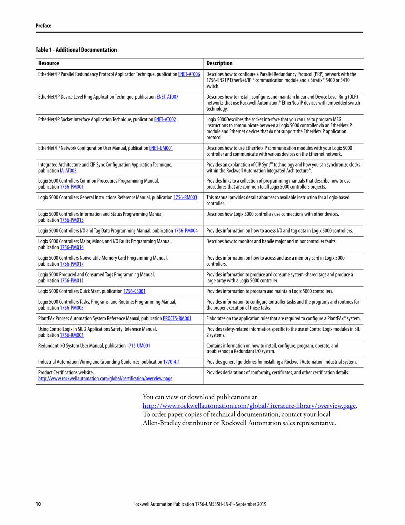
Table 1 - Additional Documentation
Resource Description
1715 Redundant I/O System Specifications Technical Data, publication 1715-TD001 Contains specifications on a Redundant I/O system.
1756 ControlLogix Controllers Technical Data, publication 1756-TD001 Contains specifications on ControlLogix controllers and redundancy modules.
ControlFLASH Firmware Upgrade Software User Manual, publication 1756-UM105 Describes how to use the ControlFLASH™ software to upgrade device firmware.
ControlFLASH Plus Quick Start Guide, publication CFP-QS001C-EN-E Describes how to use the ControlFLASH Plus™ software to upgrade device firmware.
ControlLogix Redundancy Update and Module Replacement Guidelines Reference Manual, publication 1756-RM010
Provides instructions for replacing modules or updating firmware in a powered-up redundancy system.
ControlLogix System Selection Guide, publication 1756-SG001 Provides information on how to select components for a ControlLogix system.
ControlLogix System User Manual, publication 1756-UM001 Contains information on how to install, configure, program, and operate a ControlLogix system.
ControlNet Network Configuration User Manual, publication CNET-UM001 Describes ControlNet® modules and how to use ControlNet modules with a Logix 5000 controller.
Rockwell Automation Publication 1756-UM535H-EN-P - September 2019 9
Preface
You can view or download publications at http://www.rockwellautomation.com/global/literature-library/overview.page. To order paper copies of technical documentation, contact your local Allen-Bradley distributor or Rockwell Automation sales representative.
EtherNet/IP Parallel Redundancy Protocol Application Technique, publication ENET-AT006 Describes how to configure a Parallel Redundancy Protocol (PRP) network with the 1756-EN2TP EtherNet/IP™ communication module and a Stratix® 5400 or 5410 switch.
EtherNet/IP Device Level Ring Application Technique, publication ENET-AT007 Describes how to install, configure, and maintain linear and Device Level Ring (DLR) networks that use Rockwell Automation® EtherNet/IP devices with embedded switch technology.
EtherNet/IP Socket Interface Application Technique, publication ENET-AT002 Logix 5000Describes the socket interface that you can use to program MSG instructions to communicate between a Logix 5000 controller via an EtherNet/IP module and Ethernet devices that do not support the EtherNet/IP application protocol.
EtherNet/IP Network Configuration User Manual, publication ENET-UM001 Describes how to use EtherNet/IP communication modules with your Logix 5000 controller and communicate with various devices on the Ethernet network.
Integrated Architecture and CIP Sync Configuration Application Technique, publication IA-AT003
Provides an explanation of CIP Sync™ technology and how you can synchronize clocks within the Rockwell Automation Integrated Architecture®.
Logix 5000 Controllers Common Procedures Programming Manual, publication 1756-PM001
Provides links to a collection of programming manuals that describe how to use procedures that are common to all Logix 5000 controllers projects.
Logix 5000 Controllers General Instructions Reference Manual, publication 1756-RM003 This manual provides details about each available instruction for a Logix-based controller.
Logix 5000 Controllers Information and Status Programming Manual, publication 1756-PM015
Describes how Logix 5000 controllers use connections with other devices.
Logix 5000 Controllers I/O and Tag Data Programming Manual, publication 1756-PM004 Provides information on how to access I/O and tag data in Logix 5000 controllers.
Logix 5000 Controllers Major, Minor, and I/O Faults Programming Manual, publication 1756-PM014
Describes how to monitor and handle major and minor controller faults.
Logix 5000 Controllers Nonvolatile Memory Card Programming Manual, publication 1756-PM017
Provides information on how to access and use a memory card in Logix 5000 controllers.
Logix 5000 Produced and Consumed Tags Programming Manual, publication 1756-PM011
Provides information to produce and consume system-shared tags and produce a large array with a Logix 5000 controller.
Logix 5000 Controllers Quick Start, publication 1756-QS001 Provides information to program and maintain Logix 5000 controllers.
Logix 5000 Controllers Tasks, Programs, and Routines Programming Manual, publication 1756-PM005
Provides information to configure controller tasks and the programs and routines for the proper execution of these tasks.
PlantPAx Process Automation System Reference Manual, publication PROCES-RM001 Elaborates on the application rules that are required to configure a PlantPAx® system.
Using ControlLogix in SIL 2 Applications Safety Reference Manual, publication 1756-RM001
Provides safety-related information specific to the use of ControlLogix modules in SIL 2 systems.
Redundant I/O System User Manual, publication 1715-UM001 Contains information on how to install, configure, program, operate, and troubleshoot a Redundant I/O system.
Industrial Automation Wiring and Grounding Guidelines, publication 1770-4.1 Provides general guidelines for installing a Rockwell Automation industrial system.
Product Certifications website, http://www.rockwellautomation.com/global/certification/overview.page
Provides declarations of conformity, certificates, and other certification details.
Table 1 - Additional Documentation
Resource Description
10 Rockwell Automation Publication 1756-UM535H-EN-P - September 2019

Chapter 1
About ControlLogix Redundancy Systems
The ControlLogix® Redundancy System is a system that provides greater availability. The system has greater availability because it uses a redundant chassis pair. The redundant chassis pair maintains process operation when events, such as a fault on a controller, occur that stop process operation on non-redundant systems.
The redundant chassis pair includes two synchronized ControlLogix chassis with identically specific components in each. For example, one redundancy module and at least one ControlNet® or EtherNet/IP™ communication module are required.
Controllers are typically used in redundancy systems, but are not required if your application only requires communication redundancy. Your application operates from a primary chassis, but can switch over to the secondary chassis and components if necessary.
Topic Page
Features of the ControlLogix Redundancy System 12
Redundancy System Components 13
Redundancy System Operations 15
Restrictions 18
Rockwell Automation Publication 1756-UM535H-EN-P - September 2019 11

Chapter 1 About ControlLogix Redundancy Systems
Features of the ControlLogix Redundancy System
The software and hardware components that are required to configure and use a ControlLogix redundancy system provide these features:
• Redundancy module speeds of up to 1000 Mbps when using a 1756-RM2 module with another 1756-RM2 module. Redundancy module speeds up to 100 Mbps when using a 1756-RM/A with another 1756-RM/A module, and a 1756-RM/B module with another 1756-RM/B module.
• Redundant fiber ports for crossloading; no single point of failure of a fiber cable.
• Plug-and-play-style commissioning and configuration that does not require extensive programming.
• ControlNet and EtherNet/IP network options for the redundant chassis pair.
• Easy-to-use, fiber-optic communication cable that connects redundant chassis pairs. Use the same cable for the 1756-RM2 or 1756-RM/B modules.
• Simple redundant controller configuration by using a checkbox in the Controller Properties dialog box in the Studio 5000 Automation & Engineering Design Environment® programming software.
• A redundancy system ready to accept commands and monitor the redundant system states after basic installation, connection, and powerup.
• Switchovers occur as fast as 20 ms.
• Support for these FactoryTalk® applications for Ethernet communication modules:– FactoryTalk Alarms and Events– FactoryTalk Batch– FactoryTalk PhaseManager™
• Support for CIP Sync™ technology over an EtherNet/IP network to establish time coordination across the redundant system.
• Access to remote I/O modules over an EtherNet/IP network.
• Access to 1715 Redundant I/O systems over an EtherNet/IP network.
• Ethernet socket support.
• Supports DLR topologies. For more information about DLR, see the EtherNet/IP Device Level Ring Application Technique, publication ENET-AT007.
12 Rockwell Automation Publication 1756-UM535H-EN-P - September 2019
About ControlLogix Redundancy Systems Chapter 1
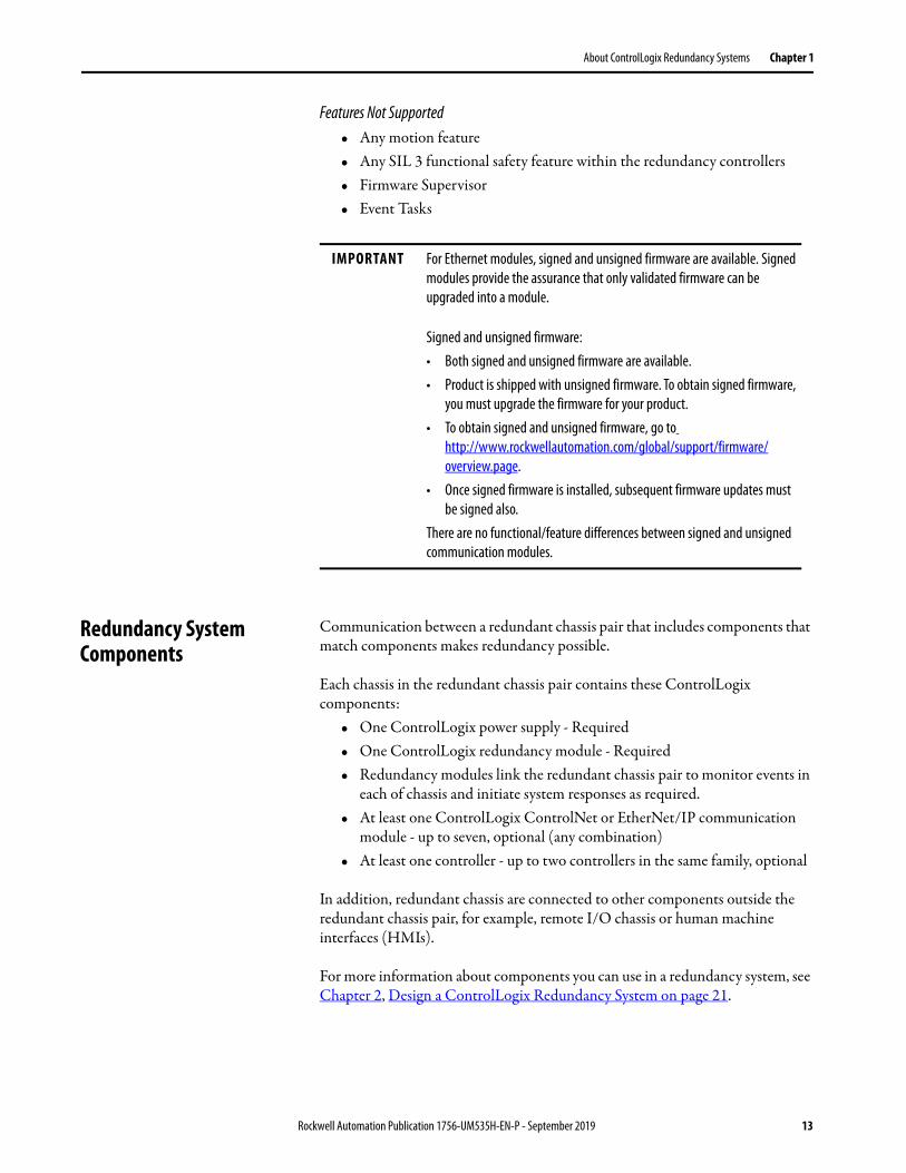
Features Not Supported• Any motion feature• Any SIL 3 functional safety feature within the redundancy controllers• Firmware Supervisor• Event Tasks
Redundancy System Components
Communication between a redundant chassis pair that includes components that match components makes redundancy possible.
Each chassis in the redundant chassis pair contains these ControlLogix components:
• One ControlLogix power supply - Required• One ControlLogix redundancy module - Required• Redundancy modules link the redundant chassis pair to monitor events in
each of chassis and initiate system responses as required.• At least one ControlLogix ControlNet or EtherNet/IP communication
module - up to seven, optional (any combination)• At least one controller - up to two controllers in the same family, optional
In addition, redundant chassis are connected to other components outside the redundant chassis pair, for example, remote I/O chassis or human machine interfaces (HMIs).
For more information about components you can use in a redundancy system, see Chapter 2, Design a ControlLogix Redundancy System on page 21.
IMPORTANT For Ethernet modules, signed and unsigned firmware are available. Signed modules provide the assurance that only validated firmware can be upgraded into a module.
Signed and unsigned firmware:• Both signed and unsigned firmware are available.• Product is shipped with unsigned firmware. To obtain signed firmware,
you must upgrade the firmware for your product.• To obtain signed and unsigned firmware, go to
http://www.rockwellautomation.com/global/support/firmware/overview.page.
• Once signed firmware is installed, subsequent firmware updates must be signed also.
There are no functional/feature differences between signed and unsigned communication modules.
Rockwell Automation Publication 1756-UM535H-EN-P - September 2019 13
Chapter 1 About ControlLogix Redundancy Systems
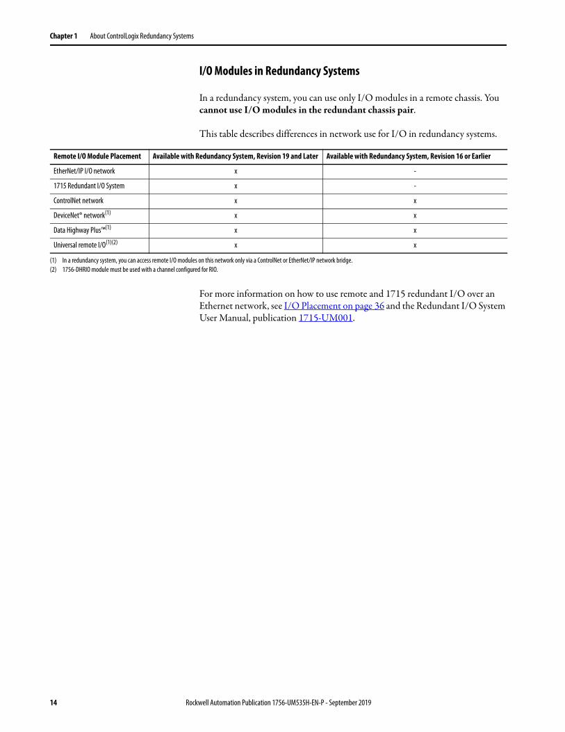
I/O Modules in Redundancy Systems
In a redundancy system, you can use only I/O modules in a remote chassis. You cannot use I/O modules in the redundant chassis pair.
This table describes differences in network use for I/O in redundancy systems.
For more information on how to use remote and 1715 redundant I/O over an Ethernet network, see I/O Placement on page 36 and the Redundant I/O System User Manual, publication 1715-UM001.
Remote I/O Module Placement Available with Redundancy System, Revision 19 and Later Available with Redundancy System, Revision 16 or Earlier
EtherNet/IP I/O network x -
1715 Redundant I/O System x -
ControlNet network x x
DeviceNet® network(1) x x
Data Highway Plus™(1) x x
Universal remote I/O(1)(2) x x
(1) In a redundancy system, you can access remote I/O modules on this network only via a ControlNet or EtherNet/IP network bridge.(2) 1756-DHRIO module must be used with a channel configured for RIO.
14 Rockwell Automation Publication 1756-UM535H-EN-P - September 2019

About ControlLogix Redundancy Systems Chapter 1
Redundancy System Operations
Once the redundancy modules in the redundant chassis pair are connected and powered, they determine which chassis is the primary chassis and which is the secondary chassis.
The redundancy modules in both the primary and secondary chassis monitor events that occur in each of the redundant chassis. If certain faults occur in the primary chassis, the redundancy modules execute a switchover to the unfaulted, secondary chassis.
System Qualification and Synchronization
When the redundant system is first started, the redundancy modules run checks on the redundant chassis. These checks determine if the chassis contain the appropriate modules and firmware to establish a redundant system. This stage of checks is referred to as qualification.
After the redundancy modules complete qualification, synchronization can take place. Synchronization is a state in which the redundancy modules execute these tasks:
• Verify that the connection between redundancy modules is ready to facilitate a switchover
• Verify that the redundant chassis continue to meet qualification requirements
• Synchronize the data between the redundant controllers, also called crossloading
This data is crossloaded:– Updated tag values– Force values– Online edits– Other project information
Synchronization always takes place immediately following qualification. Also, depending on your system configuration, synchronization takes place at the end of each program that is run within the controller project, or at other intervals that you specify.
Rockwell Automation Publication 1756-UM535H-EN-P - September 2019 15
Chapter 1 About ControlLogix Redundancy Systems
Switchovers
During redundant system operation, if certain conditions occur on the primary chassis, primary control is switched to the secondary chassis. These conditions cause a switchover:
• Loss of power
• Major fault on the controller
• Removal or insertion of any module
• Failure of any module
• Damage to a ControlNet cable or tap - This event only causes a switchover if it results in the ControlNet communication module transition to a lonely state, that is, the module does not see any devices on the network.
• Loss of an EtherNet/IP connection - This event only causes a switchover if it results in the EtherNet/IP communication module transition to a lonely state, that is, the module does not see any devices on the network.
• A program-prompted command to switchover
• A command that is issued via the Redundancy Module Configuration Tool (RMCT)
After a switchover occurs, the new primary controller continues to execute programs, which begin with the highest-priority task that had been executing on the previous primary controller.
For more information about how tasks execute after a switchover, see Crossloads, Synchronization, and Switchovers on page 116.
Your application can require some programming considerations and potential changes to accommodate a switchover. For more information on these considerations, see Chapter 7, Program the Redundant Controller on page 111.
IMPORTANT During a switchover of the fiber channels of the 1756-RM2 module, scan time encounters a delay of ~10 ms; however, the chassis always remains synched.
16 Rockwell Automation Publication 1756-UM535H-EN-P - September 2019

About ControlLogix Redundancy Systems Chapter 1
HMI Blind Time Reduction During a Switchover
HMI Blind Time is the time during a switchover from primary to secondary, when tag data from the controller is unavailable for reading or writing. HMI Blind Time is associated with visualizing process operations from an HMI. However, HMI Blind Time is applicable to any software that uses tag data, such as data loggers, alarming systems, or historians. HMI Blind Time reduction is important to increase the availability of the HMI system.
Brief communication interruption occurs between FactoryTalk Linx software and the redundant chassis pair when a switchover occurs. After the switchover is complete, communication resumes automatically.
The time between the communication (updating active data) interruption and the restoration (resumes updates) is often referred to as ‘HMI Blind Time.’
As of revision 31.052, the communication delays over Ethernet during a switchover event have been reduced significantly. The following are required to take advantage of this:
• A dedicated pair of ControlLogix Communication Modules with firmware revision 11.001 or later (1756-EN2TP, 1756-EN2TR, 1756-EN2T), that do not swap IP addresses
• ControlLogix 5570 redundancy controllers with redundancy firmware revision 31.052 or later
• FactoryTalk Linx 6.00 with the FactoryTalk Linx patch available from Rockwell Automation Knowledgebase Answer ID 1073788, or later versions of FactoryTalk Linx.
• Redundant ControlLogix Controller shortcut type in FactoryTalk Linx that points to the Primary and Secondary controllers through the communication modules, without swapping IP addresses. For information on shortcuts in FactoryTalk Linx, see the FactoryTalk Linx Getting Results Guide, publication LNXENT-GR001.
IMPORTANT • Prior to firmware revision 30.051, the communication delays apply only when communication is exclusively over EtherNet/IP networks.
• With firmware revision 30.051 or later, the communication delays apply to both EtherNet/IP and ControlNet networks.
IMPORTANT FactoryTalk Linx software is part of FactoryTalk Services, which has been releasing a series of Service Releases (SRs) that are backward compatible with any CPR 9 products. Existing and new users who are using FactoryTalk View version 5.0 (CPR9) or later can use the HMI Blind Time feature.
Rockwell Automation Publication 1756-UM535H-EN-P - September 2019 17

Chapter 1 About ControlLogix Redundancy Systems
Some communication delays can occur during qualification. The existence and duration of these delays depend on:
• Quantity and types of tags on scan in FactoryTalk Linx software• Client screen and tag update rates (e.g. FactoryTalk Live Data/FactoryTalk
Historian)• Number of data subscribers (i.e. FactoryTalk Alarms and Events,
FactoryTalk Batch)• Size of the application in the redundant controller• Controller loading, which includes the following:
• Number of tasks and scan rates (assumes no continuous task)• Number of programs• Memory usage• Null task percentage available• Network traffic
Restrictions There are restrictions that you must consider when using a redundancy system. Most of these restrictions apply to all redundancy system revisions. Exceptions are noted:
• See the release notes of the redundancy bundles for compatible products, versions, and revisions
• The redundant controller program cannot contain these tasks:– Event tasks– Inhibited tasksFor recommendations and requirements that are related to programming the redundant controller, see Program the Redundant Controller on page 111.
• You cannot use the Match Project to Controller feature available in Studio 5000 Logix Designer® in a redundancy system.
• You cannot use program motion in a redundant controller program.• You cannot use consumed Unicast connections in a redundancy system. If
you attempt to use consumed Unicast connections, disqualification occurs and qualification of an unsynchronized redundant chassis pair is not allowed. You can use produced Unicast connections that remote consumers consume.
• Outputs controlled by IOT instructions are not guaranteed to maintain a bumpless transition during a switchover. Due to this, it is recommended to avoid using IOT instructions within a redundancy system.
• You can use a maximum of two controllers of the same family, and seven ControlNet or EtherNet/IP communication modules in each chassis of a redundant chassis pair.
• You can execute the tasks that were supported previously in a redundancy system, revision 19.052 or greater.
18 Rockwell Automation Publication 1756-UM535H-EN-P - September 2019

About ControlLogix Redundancy Systems Chapter 1
This graphic shows an example ControlLogix redundancy system, revision 19.053 or greater, which uses EtherNet/IP networks.
Figure 1 - Example ControlLogix Redundancy System, Revision 19.053 or greater, using an EtherNet/IP Network
22
CH2 CH1 OK CH2 CH1 OK
Redundant Chassis Pair
EtherNet/IP Switch
1756 ControlLogix I/O
Workstation
1715 Redundant I/O PowerFlex® Drive Connected via 1783-ETAP
1734 POINT I/O™
Rockwell Automation Publication 1756-UM535H-EN-P - September 2019 19

Chapter 1 About ControlLogix Redundancy Systems
Notes:
20 Rockwell Automation Publication 1756-UM535H-EN-P - September 2019
Chapter 2
Design a ControlLogix Redundancy System
This chapter explains how to use the required and optional components to design a redundancy system.
Redundant Chassis You can use any ControlLogix® or ControlLogix-XT™ chassis in a redundant chassis pair as long as the two chassis that are used are the same size. For example, if the primary chassis in your redundant chassis pair uses a 1756-A4 chassis, the secondary chassis must use a 1756-A4 chassis.
Topic Page
Redundant Chassis 21
Controllers in Redundant Chassis 22
EtherNet/IP Networks with Redundant Systems 28
ControlNet Networks with Redundant Systems 30
Other Communication Networks 34
I/O Placement 36
Using HMI 38
Optional Software 41
IMPORTANT There are module series level, firmware revision, and software version requirements for redundancy systems.For more information on these module series level, firmware revision, and version requirements, see the current release notes at: http://www.rockwellautomation.com/global/literature-library/overview.page
TIP When using 1756-L72, 1756-L73, 1756-L74, or 1756-L75 Redundant controllers in your system, you must use firmware revision 19.053 or greater. When using a 1756-L71 Redundant controller, you must use firmware 20.054 or greater.
Rockwell Automation Publication 1756-UM535H-EN-P - September 2019 21

Chapter 2 Design a ControlLogix Redundancy System
Redundant Chassis Configuration Requirements
These configuration parameters must match for the components in a redundant chassis pair during normal system operation:
• Module type
• Chassis size
• Slot placement
• Firmware revision
• Series level. See page 25
Figure 2 - Example of Redundant Chassis Pair
Controllers in Redundant Chassis
Remember these points when you place controllers in the redundant chassis pair:
• Controllers are typically included, but not required, in redundancy systems. If you have a redundancy system without controllers, you have only a redundant gateway rack.
• You can place up to two controllers in the same chassis. When you use two controllers in the same chassis, they must be of the same product family. The series of the controller in the primary and secondary chassis do not need to match.
For example, you cannot place a ControlLogix 5560 controller and a ControlLogix 5570 controller in the same chassis.
CH2 CH1 OK CH2 CH1 OK
0 1 2 3 0 1 2 3
IMPORTANT When using a ControlLogix redundancy system, revision 16.081 or earlier, you cannot use two 1756-L64 controllers in the same chassis. You can, however, use a 1756-L64 controller in the same chassis as a 1756-L61, 1756-L62, or 1756-L63 controller.
22 Rockwell Automation Publication 1756-UM535H-EN-P - September 2019

Design a ControlLogix Redundancy System Chapter 2
• You can use different catalog numbers from the same product family in the same chassis. For example, you can use two ControlLogix 5560 controllers in a chassis.
• Each controller must have enough data memory to store twice the amount of tag data that is associated with a redundant controller project.
• Each controller must have enough I/O memory to store twice the amount of I/O memory used. To check the I/O memory that is used and available, access the Memory tab of the Controller Properties dialog box in the programming software.
For more information about data and I/O memory, see Knowledgebase Answer ID 28972.
• When you use the redundancy system update (RSU) feature to update a redundancy system while the system continues operation, the updated secondary controllers must provide the same or greater memory than the primary controllers.
A secondary controller provides greater memory than the primary controller if it is a higher catalog number, for example, a 1756-L63 primary controller and a 1756-L65 secondary controller.
This table describes the secondary controllers to which you can upgrade, based on the primary controller that is used, when using RSU.
Differences in controller types between chassis can exist only during the system upgrade process. When you complete the system upgrade, the controllers in the redundant chassis pair must match for the system to synchronize.
Primary Secondary
1756-L61 1756-L61, 1756-L62, 1756-L63, 1756-L64, 1756-L65
1756-L62 1756-L62, 1756-L63, 1756-L64, 1756-L65
1756-L63 1756-L63, 1756-L64, 1756-L65
1756-L64 1756-L64, 1756-L65
1756-L65 1756-L65
1756-L71 1756-L71, 1756-L72, 1756-L73, 1756-L74, 1756-L75
1756-L72 1756-L72, 1756-L73, 1756-L74, 1756-L75
1756-L73 1756-L73, 1756-L74, 1756-L75
1756-L74 1756-L74, 1756-L75
1756-L75 1756-L75
Rockwell Automation Publication 1756-UM535H-EN-P - September 2019 23

Chapter 2 Design a ControlLogix Redundancy System
Plan for Controller Connections
Consider these conditions when you plan controller connection use:• ControlLogix 5560 controllers provide 250 total connections.• ControlLogix 5570 controllers provide 500 total connections.
If you use the redundant controller at, or very near the connection limits, you can experience difficulty synchronizing your chassis.
Redundancy Modules in Redundant Chassis
Two redundancy modules, one in each chassis of the redundant chassis pair, jointly supervise the control system operating states and transitions, which establishes the framework for system redundancy. This bridge between chassis facilitates the exchange of control data and synchronization of operations.
The redundancy modules let you commission the redundant system in a plug-and-play manner without any programming. You connect a redundancy module pair with the default configuration in the redundant chassis pair and configure the redundant system.
You can establish redundancy between chassis in either of these manners:
• Insert a redundancy module pair into two powered chassis that contain redundancy-compliant components and redundancy-enabled application programs, and then connect the redundancy modules.
• Insert and connect the redundancy modules in two chassis and then insert redundancy-compliant components into each chassis.
Once the redundant chassis pair contains all desired components and is powered, no further tasks are required in the redundancy modules to activate system redundancy. The redundancy modules automatically determine the operational state of each of the chassis pair and are ready to accept commands and provide system monitoring.
IMPORTANT You are not required to develop any programming to migrate from a non-redundant to a redundancy system if your application meets these conditions:• Your application meets the points that are listed in Restrictions on
page 18.• The controller properties dialog box in your project has Redundancy
enabled.
24 Rockwell Automation Publication 1756-UM535H-EN-P - September 2019

Design a ControlLogix Redundancy System Chapter 2
Communication Modules in Redundant Chassis
Remember these points when placing ControlLogix ControlNet® andEtherNet/IP™ communication modules in the redundant chassis pair:
• You must use enhanced communication modules in redundancy systems. Enhanced communication modules contain a ‘2’ in their catalog number. For example, the 1756-EN2T module.
• Standard ControlNet and EtherNet/IP communication modules are not supported. Standard communication modules contain a 'B' in their catalog number. For example, the 1756-ENBT module.
• You can use the 1756-EN2TR module only with a redundancy system, revision 19.052 or later.
• You can use the 1756-EN2F module only with a redundancy system, revision 20.054 or later.
• You can use the 1756-EN2TP module only with a redundancy system, revision 31.052 or later.
• You can use any combination of up to seven enhanced communication modules in each redundant chassis.
• If you use a ControlNet network in your redundant chassis pair, you must have two ControlNet communication modules outside the redundant chassis pair. When you assign node address numbers, assign the lowest node number address to a ControlNet communication module outside the redundant chassis pair.
For more information, see Use at Least Four ControlNet Network Nodes on page 30 through Assign Lowest Node Numbers to Remote ControlNet Modules on page 31.
• You cannot use Series A ControlNet communication modules in a redundancy system.
• The Series for EtherNet/IP communication modules is not required to match in a partnered set. However, the firmware levels must be the same in a partnered set. Also, if your application requires a feature specific to a module series level, you must use the same series level for each module in a partnered set.
For example, only the 1756-EN2T/C communication module only offers the double-data rate (DDR) feature. You must use 1756-EN2T/C modules in each chassis of the redundant chassis pair to use DDR.
Rockwell Automation Publication 1756-UM535H-EN-P - September 2019 25
Chapter 2 Design a ControlLogix Redundancy System
• Do not use the USB ports of communication modules to access the redundant system network while the system is running, that is, online. Use of the USB ports while online can result in a loss of communication after a switchover.
Plan for Communication Module Connections
A CIP™ connection is a point-to-point communication mechanism that is used to transfer data between a producer and a consumer. These mechanisms are examples of CIP connections:
• Logix 5000™ controller message transfer to Logix 5000 controller
• I/O or produced tag
• Program upload
• RSLinx® DDE/OPC client
• PanelView™ polling of a Logix 5000 controller
ControlLogix ControlNet communication modules provide 131 total CIP connections. Consider these points when using CIP connections with ControlLogix ControlNet communication modules:
• Three of the 131 CIP connections are reserved for redundancy. The three redundant-system CIP connections always appear to be in use, even when no connections are open.
• You can use the remaining 128 CIP connections in any manner that your application requires, such as the examples listed previously.
ControlLogix EtherNet/IP communication modules provide 259 total CIP connections. Consider these points when using CIP connections with ControlLogix EtherNet/IP communication modules:
• Three of the 259 CIP connections are reserved for redundancy.
• You can use the remaining 256 connections in any manner that your application requires, such as the examples listed previously.
26 Rockwell Automation Publication 1756-UM535H-EN-P - September 2019

Design a ControlLogix Redundancy System Chapter 2
Power Supplies and Redundant Power Supplies in Redundancy Systems
Typically, redundancy systems use standard power supplies. You can choose to use redundant power supplies to maintain power to a ControlLogix chassis if one of the supplies loses power. Use these hardware components to connect redundant power supplies:
• Two redundant power supplies for each chassis
• One 1756-PSCA chassis adapter for each redundant chassis
• Two 1756-CPR cables for each redundant chassis to connect the power supplies to the 1756-PSCA adapter
• Optional, user-supplied annunciator wiring to connect the power supplies to remote input modules
Figure 3 - Redundant Power Supplies with Redundant Chassis
For more information about redundant power supplies, see the ControlLogix System Selection Guide, publication 1756-SG001.
CH2 CH1 OK
2
CH2 CH1 OK
2
1756-PA75R or 1756-PB75R Power Supplies
Primary Chassis
1756-CPR Cables
Annunciator Wiring(optional)1756-CPR
Cables
Secondary Chassis
Rockwell Automation Publication 1756-UM535H-EN-P - September 2019 27
Chapter 2 Design a ControlLogix Redundancy System
EtherNet/IP Networks with Redundant Systems
The use of EtherNet/IP networks in a redundancy system is primarily dependent on your system revision.
For more information on how to use an EtherNet/IP network in your redundancy system, see Configure the EtherNet/IP Network on page 65.
Unicast Functionality
Redundancy systems support unicast produced tags. Unicast consumed tags are not supported in redundancy systems. Unicast I/O is not supported in a redundancy system.
Possible Communication Delays on EtherNet/IP and ControlNet Networks
The connection between a component and the redundant chassis pair can experience brief communication delays during a switchover. After the switchover is complete, communication resumes automatically.
These connection types can experience the communication delay when the switchover occurs:
• HMI to redundant chassis pair• FactoryTalk® Batch server to redundant chassis pair• FactoryTalk Alarms and Events Service to redundant chassis pair
IMPORTANT A remote chassis can be accessed over an EtherNet/IP network by using any EtherNet/IP module that works in a non-redundant chassis with no additional firmware requirement with the following exception. If the remote chassis contains a controller that consumes a tag that is produced in the redundant chassis pair, it can only consume the tag with the required firmware revisions.
IMPORTANT • Prior to firmware revision 30.051, the communication delays apply only when communication is exclusively over EtherNet/IP networks.
• With firmware revision 30.051 or later, the communication delays apply to both EtherNet/IP and ControlNet networks.
28 Rockwell Automation Publication 1756-UM535H-EN-P - September 2019
Design a ControlLogix Redundancy System Chapter 2
Bridge from an EtherNet/IP Network to a ControlNet Network
Bridge from an EtherNet/IP network to a ControlNet network if you must maintain the connection between the component and a redundant chassis pair during a switchover.
See HMI Blind Time Reduction During a Switchover on page 17.
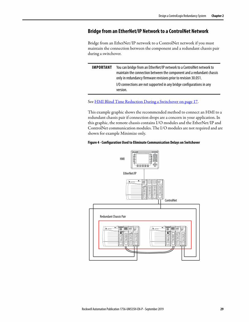
This example graphic shows the recommended method to connect an HMI to a redundant chassis pair if connection drops are a concern in your application. In this graphic, the remote chassis contains I/O modules and the EtherNet/IP and ControlNet communication modules. The I/O modules are not required and are shown for example Minimize only.
Figure 4 - Configuration Used to Eliminate Communication Delays on Switchover
IMPORTANT You can bridge from an EtherNet/IP network to a ControlNet network to maintain the connection between the component and a redundant chassis only in redundancy firmware revisions prior to revision 30.051.I/O connections are not supported in any bridge configurations in any version.
CH2 CH1 OK CH2 CH1 OK
ControlNet
EtherNet/IP
HMI
Redundant Chassis Pair
Rockwell Automation Publication 1756-UM535H-EN-P - September 2019 29
Chapter 2 Design a ControlLogix Redundancy System
ControlNet Networks with Redundant Systems
ControlNet networks are used to connect redundant control chassis to remoteI/O and to other devices in the system.
ControlNet Network Requirements
If you use a ControlNet network in your redundancy system, you must consider the following when using ControlNet networks in your redundancy system:
• Use at Least Four ControlNet Network Nodes
• Assign Lowest Node Numbers to Remote ControlNet Modules
• Set Partnered ControlNet Module Switches to the Same Address
• Reserve Consecutive Node Addresses for Partner Modules
Use at Least Four ControlNet Network Nodes
With redundant systems, at least four ControlNet network nodes are required. This configuration is required because two or more ControlNet nodes must be used with the two ControlNet modules that are used in the redundant chassis. One of the two nodes outside of the redundant chassis must be at a lower node address than the ControlNet modules in the redundant chassis.
If your ControlNet uses fewer than four nodes, and a switchover occurs, connections can drop and outputs connected to that node can change state during the switchover.
You can include these ControlNet modules and redundant ControlNet nodes:
• ControlNet bridges in remote chassis
• Any other ControlNet devices on the ControlNet network
• A workstation running RSLinx Classic communication software that is connected via a ControlNet network
IMPORTANT A remote chassis can be accessed over a ControlNet network that uses any ControlNet module that works in a non-redundant chassis with no additional firmware requirement.
30 Rockwell Automation Publication 1756-UM535H-EN-P - September 2019
Design a ControlLogix Redundancy System Chapter 2
Assign Lowest Node Numbers to Remote ControlNet Modules
Do not assign the lowest ControlNet node addresses to ControlNet modules in the redundant chassis pair.
If you assign the lowest ControlNet node addresses to ControlNet modules in the redundant chassis pair, you can experience these system behaviors:
• Upon a switchover, you can lose communication with I/O modules, produced tags, and consumed tags.
• If you remove a ControlNet module from the redundant chassis, it can result in lost communication with I/O modules, produced tags, and consumed tags.
• If the entire system loses power, you can be required to cycle power to the primary chassis to restore communication.
Set Partnered ControlNet Module Switches to the Same Address
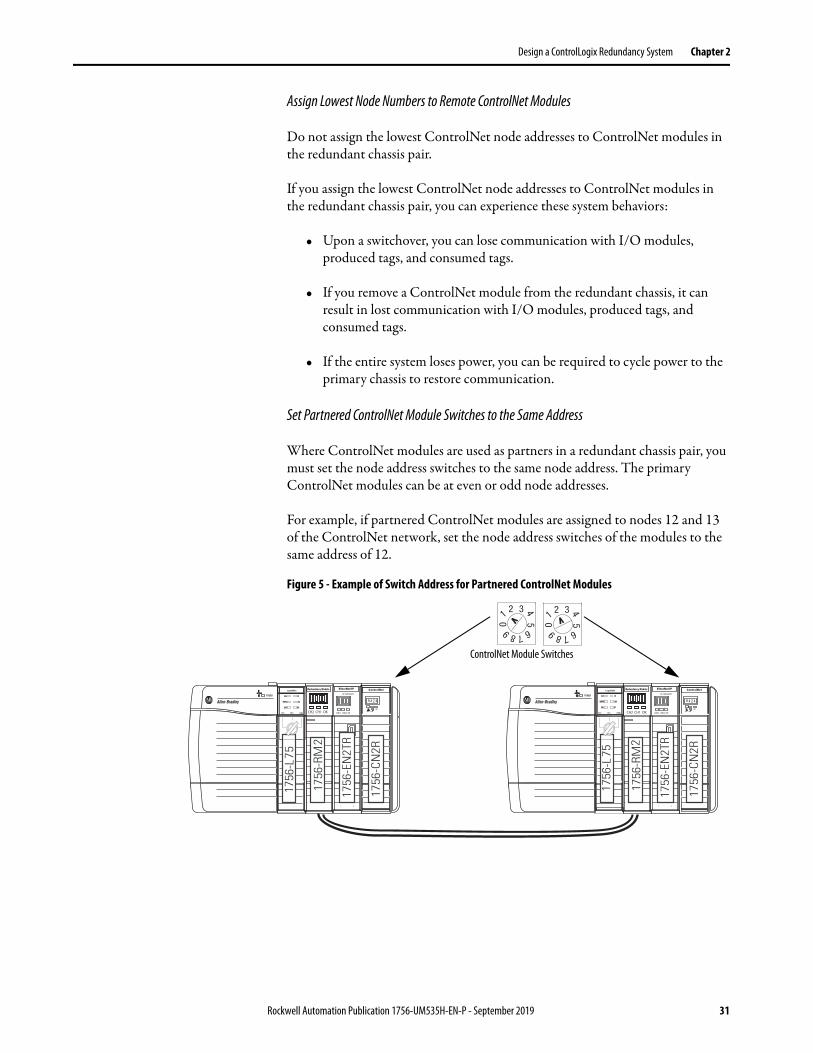
Where ControlNet modules are used as partners in a redundant chassis pair, you must set the node address switches to the same node address. The primary ControlNet modules can be at even or odd node addresses.
For example, if partnered ControlNet modules are assigned to nodes 12 and 13 of the ControlNet network, set the node address switches of the modules to the same address of 12.
Figure 5 - Example of Switch Address for Partnered ControlNet Modules
CH2 CH1 OK CH2 CH1 OK
ControlNet Module Switches
Rockwell Automation Publication 1756-UM535H-EN-P - September 2019 31

Chapter 2 Design a ControlLogix Redundancy System
Reserve Consecutive Node Addresses for Partner Modules
Where ControlNet modules are used as partners in redundant chassis, plan consecutive node numbers for those partnered modules. Plan for consecutive node addresses because the redundant system automatically assigns the consecutive node address to the secondary ControlNet module.
For example, partnered ControlNet modules with address switches set at 12 are assigned ControlNet node numbers 12 and 13 by the system.
Figure 6 - Example of Redundant ControlNet Modules at Consecutive Addresses
TIP The primary chassis always assumes the lower of the two node addresses.
CH2 CH1 OK CH2 CH1 OK
Node 12 Node 13
ControlNet Module Switches
Primary Chassis Secondary Chassis
32 Rockwell Automation Publication 1756-UM535H-EN-P - September 2019
Design a ControlLogix Redundancy System Chapter 2
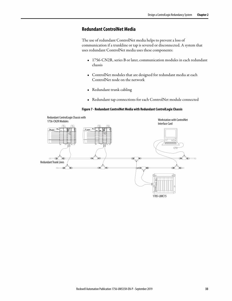
Redundant ControlNet Media
The use of redundant ControlNet media helps to prevent a loss of communication if a trunkline or tap is severed or disconnected. A system that uses redundant ControlNet media uses these components:
• 1756-CN2R, series B or later, communication modules in each redundant chassis
• ControlNet modules that are designed for redundant media at each ControlNet node on the network
• Redundant trunk cabling
• Redundant tap connections for each ControlNet module connected
Figure 7 - Redundant ControlNet Media with Redundant ControlLogix Chassis
Redundant ControlLogix Chassis with 1756-CN2R Modules
Redundant Trunk Lines
Workstation with ControlNet Interface Card
1785-L80C15
Rockwell Automation Publication 1756-UM535H-EN-P - September 2019 33

Chapter 2 Design a ControlLogix Redundancy System
Other Communication Networks
You can use only EtherNet/IP and ControlNet networks, and corresponding modules, in redundancy systems.
You can bridge to other communication networks outside of the redundant chassis. For example, you can bridge to a universal remote I/O network via a remote chassis.
Figure 8 - Example of Bridging to Remote I/O on Various Networks
IMPORTANT Do not use the redundant chassis to bridge between networks. Bridging through the redundant chassis to the same or different networks, or routing messages through redundant chassis is not supported.
CH2 CH1 OKCH2 CH1 OK
Chassis Bridge from ControlNet to Remote I/O Networks
To Universal I/O Network
To EtherNet/IP NetworkIMPORTANT: Cannot bridge to I/O modules.
To DeviceNet® Network
HMIWorkstation
Ethernet Switch
Primary Chassis Secondary Chassis
34 Rockwell Automation Publication 1756-UM535H-EN-P - September 2019

Design a ControlLogix Redundancy System Chapter 2
You can bridge these networks via a remote chassis:• ControlNet• DeviceNet• EtherNet/IP• Universal remote I/O• Data Highway Plus™
This table indicates what system components to use with each network that is connected to a redundant system.
Table 1 - Communication Networks Available for Use with Redundancy Systems
Network Connection to Redundant System Component
I/O HMI
ControlNet Directly to redundant chassis Yes Yes
Via a bridge No Yes
DeviceNet Via a bridge Yes Yes
EtherNet/IP Directly to redundant chassis Yes - Redundancy System, Revision 19.052 or later
Yes(1)
(1) Prior to redundancy firmware revision 30.051, you can connect the HMI to the redundant chassis pair via a bridge from an EtherNet/IP network to a ControlNet network to help prevent a brief loss of communication with the redundant chassis pair if a switchover occurs. For more information, see Possible Communication Delays on EtherNet/IP and ControlNet Networks on page 28.
Via a bridge No Yes
Universal remote I/O Via a bridge Yes Yes
Data Highway Plus Via a bridge Yes Yes
Rockwell Automation Publication 1756-UM535H-EN-P - September 2019 35

Chapter 2 Design a ControlLogix Redundancy System
I/O Placement In a redundancy system, you can place I/O modules in these locations:
• Same ControlNet network as redundant controllers and communication modules
• Same EtherNet/IP network as redundant controllers and communication modules
• DeviceNet network that is connected via a bridge
• Universal remote I/O network that is connected via a bridge
1715 Redundant I/O Systems
With a redundancy system revision 19.052 or greater, you can connect to 1715 Redundant I/O systems over an EtherNet/IP network.
The 1715 Redundant I/O system lets a controller communicate to a remote, redundant I/O chassis over an EtherNet/IP network. The 1715 Redundant I/O system provides high availability and redundancy for critical processes by using a redundant adapter pair and multiple I/O modules that have diagnostics and are easily replaceable.
The 1715 Redundant I/O system consists of one, two-slot, adapter base unit that houses a redundant adapter pair. The adapter base unit is connected to up to 8, three-slot, I/O base units, which can hold up to 24 fully configurable digital and analog I/O modules. You can configure a 1715 Redundant I/O system in a Ring or Star topology.
Each 1715 Redundant I/O system uses one IP address as the primary IP address for all communication. The redundant adapter pair consists of two active modules, a primary adapter and its partner, a secondary module.
For more information about the 1715 Redundant I/O system, see the Redundant I/O System User Manual, publication 1715-UM001.
IMPORTANT You cannot install I/O modules in the redundant chassis pair. You can only install I/O modules in remote locations that are accessed over the networks in this list.You can connect to remote I/O modules over an EtherNet/IP network in a redundancy system, revision 19.052 or later.
36 Rockwell Automation Publication 1756-UM535H-EN-P - September 2019

Design a ControlLogix Redundancy System Chapter 2
Figure 9 - Example of I/O Placement Options
CH2 CH1 OK CH2 CH1 OK
Bridging Chassis
1771 Chassis with 1771-ASB
Universal remote I/ODeviceNet
DeviceNet Device Control Tower™
Primary Chassis Secondary Chassis
1715 Redundant I/O
EtherNet/IP
EtherNet/IP Switch
Workstation
EtherNet/IP
ControlNet
1734 POINT I/O™
Rockwell Automation Publication 1756-UM535H-EN-P - September 2019 37
Chapter 2 Design a ControlLogix Redundancy System
Using HMI Depending on the network that is used to connect the redundant system to HMIs, plan for certain placement and configuration requirements. You can connect an HMI to a primary chassis over either of these networks:
• EtherNet/IP
• ControlNet
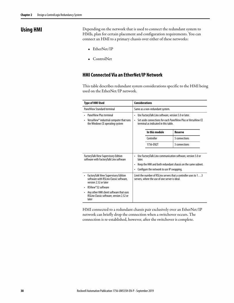
HMI Connected Via an EtherNet/IP Network
This table describes redundant system considerations specific to the HMI being used on the EtherNet/IP network.
HMI connected to a redundant chassis pair exclusively over an EtherNet/IP network can briefly drop the connection when a switchover occurs. The connection is re-established, however, after the switchover is complete.
Type of HMI Used Considerations
PanelView Standard terminal Same as a non-redundant system.
• PanelView Plus terminal• VersaView® industrial computer that runs
the Windows CE operating system
• Use FactoryTalk Linx software, version 5.0 or later.• Set aside connections for each PanelView Plus or VersaView CE
terminal as indicated in this table.
FactoryTalk View Supervisory Edition software with FactoryTalk Linx software
• Use FactoryTalk Linx communication software, version 5.0 or later.
• Keep the HMI and both redundant chassis on the same subnet.• Configure the network to use IP swapping.
• FactoryTalk View Supervisory Edition software with RSLinx Classic software, version 2.52 or later
• RSView®32 software• Any other HMI client software that uses
RSLinx Classic software, version 2.52 or later
Limit the number of RSLinx servers that a controller uses to 1…3 servers, where the use of one server is ideal.
In this module Reserve
Controller 5 connections
1756-EN2T 5 connections
38 Rockwell Automation Publication 1756-UM535H-EN-P - September 2019
Design a ControlLogix Redundancy System Chapter 2
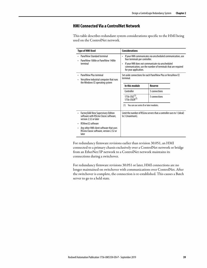
HMI Connected Via a ControlNet Network
This table describes redundant system considerations specific to the HMI being used on the ControlNet network.
For redundancy firmware revisions earlier than revision 30.051, an HMI connected to a primary chassis exclusively over a ControlNet network or bridge from an EtherNet/IP network to a ControlNet network maintains its connections during a switchover.
For redundancy firmware revisions 30.051 or later, HMI connections are no longer maintained on switchover with communications over ControlNet. After the switchover is complete, the connection is re-established. This causes a Batch server to go to a held state.
Type of HMI Used Considerations
• PanelView Standard terminal• PanelView 1000e or PanelView 1400e
terminal
• If your HMI communicates via unscheduled communication, use four terminals per controller.
• If your HMI does not communicate via unscheduled communication, use the number of terminals that are required for your application.
• PanelView Plus terminal• VersaView industrial computer that runs
the Windows CE operating system
Set aside connections for each PanelView Plus or VersaView CE terminal.
• FactoryTalk View Supervisory Edition software with RSLinx Classic software, version 2.52 or later
• RSView32 software• Any other HMI client software that uses
RSLinx Classic software, version 2.52 or later
Limit the number of RSLinx servers that a controller uses to 1 (ideal) to 3 (maximum).
In this module Reserve
Controller 5 connections
1756-CN2(1),1756-CN2R(1)
(1) You can use series B or later modules.
5 connections
Rockwell Automation Publication 1756-UM535H-EN-P - September 2019 39

Chapter 2 Design a ControlLogix Redundancy System
Figure 10 shows an example of how to connect an HMI to a primary controller over a ControlNet network.
Figure 10 - Connection from HMI Over a ControlNet Network
For an example of how to connect an HMI to a redundant chassis pair over a path that bridges from an EtherNet/IP network to a ControlNet network, see Bridge from an EtherNet/IP Network to a ControlNet Network on page 29.
CH2 CH1 OK CH2 CH1 OK
CH2 CH1 OKCH2 CH1 OK
ControlNet
HMI
Redundant Chassis Pair
ControlNet
40 Rockwell Automation Publication 1756-UM535H-EN-P - September 2019
Design a ControlLogix Redundancy System Chapter 2
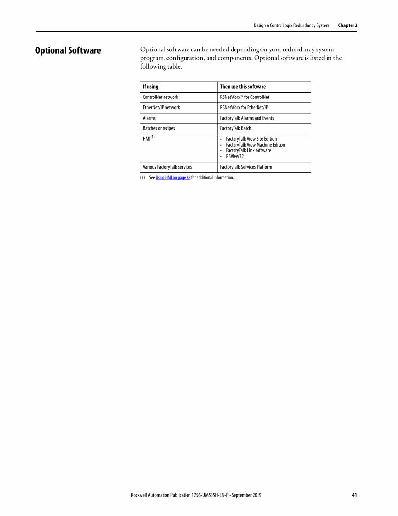
Optional Software Optional software can be needed depending on your redundancy system program, configuration, and components. Optional software is listed in the following table.
If using Then use this software
ControlNet network RSNetWorx™ for ControlNet
EtherNet/IP network RSNetWorx for EtherNet/IP
Alarms FactoryTalk Alarms and Events
Batches or recipes FactoryTalk Batch
HMI(1)
(1) See Using HMI on page 38 for additional information.
• FactoryTalk View Site Edition• FactoryTalk View Machine Edition• FactoryTalk Linx software• RSView32
Various FactoryTalk services FactoryTalk Services Platform
Rockwell Automation Publication 1756-UM535H-EN-P - September 2019 41

Chapter 2 Design a ControlLogix Redundancy System
Notes:
42 Rockwell Automation Publication 1756-UM535H-EN-P - September 2019

Chapter 3
Install the Redundancy System
Before You Begin Complete these tasks before you install the redundancy system:
• Verify that you have the components that are required to install your system.
• Read and understand the safety and environmental considerations explained in the installation instruction publication for each component.
• Order a 1756-RMCx fiber-optic communication cable if you do not have one.
• If you choose to make your own fiber-optic cable for lengths that the 1756-RMCx catalog numbers do not support, refer to Fiber-optic Cable on page 56.
Redundancy System Quick Start
See these Quick Start steps when configuring your system for the first time.
1. Review the release notes for the firmware bundle that you are installing. Make sure that you have compatible hardware and the correct firmware revisions.
2. Install/update the workstation software and firmware bundle.
Software applications that are needed include:• Studio 5000 Logix Designer® application• RSLinx® Classic communication software• Redundancy Module Configuration Tool (RMCT). See Install the
Hardware on page 45
Topic Page
Before You Begin 43
Redundancy System Quick Start 43
Install the Hardware 45
Connect the Redundancy Modules 52
Update Redundant Firmware 58
Designate the Primary and Secondary Chassis 61
IMPORTANT If RSLinx Classic software is already on your system, make sure to shut it down before installing/upgrading software.
Rockwell Automation Publication 1756-UM535H-EN-P - September 2019 43

Chapter 3 Install the Redundancy System
3. To begin the hardware installation, determine the location of your modules in the chassis of the system. Plug in the communication modules, controller, and redundancy modules into the chassis, matching partners slot for slot.
Install the following:• The first chassis and power supply, see page 45.• The first chassis communication modules.a. Determine the IP address for your Ethernet communication modules.
Both Ethernet communication modules of the same pair have the same IP address.
b. Set both Ethernet communication modules to the same IP address. (This rule also applies to ControlNet® networks for node addresses.) See Configure the EtherNet/IP Network on page 65.
• The first chassis controller.• The first chassis redundancy module, see page 46.• The second chassis, power supply, communication modules, controller,
and redundancy module. See page 52.
4. Plug in the fiber-optic communication cable to connect the redundancy modules in both chassis. See Connect the Redundancy Modules on page 52.
5. Upgrade the firmware of the redundant chassis modules. See Update Redundant Firmware on page 58.a. Apply power to the first chassis.b. Launch ControlFLASH™ or ControlFLASH Plus™ software and
upgrade the firmware.c. Upgrade the firmware of the redundancy module and verify that the
status is PRIM.d. Update all remaining modules in the chassis using ControlFLASH or
ControlFLASH Plus software.e. Power off the first chassis.f. Power on the second chassis.g. Follow the same update process as the first chassis.h. Power off the second chassis.
6. Designate the primary chassis. See Designate the Primary and Secondary Chassis on page 61.a. Verify that power is removed from both chassis.b. Apply power to the chassis you want designated as the primary. Wait for
the status indicator to display PRIM.c. Apply power to the chassis you want designated as the secondary.
44 Rockwell Automation Publication 1756-UM535H-EN-P - September 2019

Install the Redundancy System Chapter 3
Install the Hardware Follow these steps to configure and install the hardware components of your system.
Install the First Chassis
When you install a redundancy system, install one chassis, and its necessary components, at a time.
Module Placement and Partnering
Each pair of controllers and communication modules must be composed of compatible partner modules. Two modules in the same slot are considered as compatible partners only if they contain compatible hardware and firmware and other rules that the module can enforce. Either the module in the primary chassis or its partner in the secondary chassis determines the compatibility status (Compatible or Incompatible).
The redundancy module pair must occupy the same slots in their respective chassis. The redundancy module pair does not consider the chassis pair to be partnered if the redundancy modules are placed in different slots. This outcome is true even if the partners of other modules are present in the same slot.
The redundancy module prevents certain redundancy operations, such as Qualification, if incompatible modules reside in the redundant-control chassis pair.
Complete these tasks to install the first chassis in the redundant chassis pair:• Install the Redundancy Module
IMPORTANT For best performance, place the redundancy module in the chassis as close as possible to the controller.
TIP Do not apply power to the system until both chassis and their components are installed.
Then follow the steps that are described in Update Redundant Firmware on page 58 to determine when to power each chassis.
Rockwell Automation Publication 1756-UM535H-EN-P - September 2019 45
Chapter 3 Install the Redundancy System
Install the Redundancy Module
You must install one redundancy module in each chassis that is planned for your system. Available modules are as follows:
• 1756-RM2
• 1756-RM2XT• 1756-RM/A• 1756-RM/B• 1756-RMXT
Installation Requirements
Before you install the module, be sure to note the following:• Understand redundant systems and redundant media• Verify that the planned modules for each redundant chassis of the pair are
identical - including firmware revisions• Verify that your redundancy firmware revision is compatible with your
planned redundant chassis modules• The 1756-RM/B module offers a higher level of performance than a
1756-RM/A module. Both modules can coexist in a redundant system, but the highest system performance is achieved when the 1756-RM/B modules are used together when used with a ControlLogix® 5570 controller.
• The 1756-RM2 module, when used with a ControlLogix 5570 controller, offers higher crossload speeds than the 1756-RM/B module.
IMPORTANT Do not connect the primary redundancy module to the secondary redundancy module until all other components that are used in the redundant chassis pair are installed, updated to the correct firmware revision, and configured.
IMPORTANT Redundancy bundles version 24.052 and greater support only 1756-RM2 and 1756-RM2XT modules.
IMPORTANT 1756-RM2 or 1756-RM2XT modules can only be used with other 1756-RM2 or 1756-RM2XT modules. You cannot mix 1756-RM2 and 1756-RM2XT modules with 1756-RM/A, 1756-RM/B, or 1756-RMXT modules.
46 Rockwell Automation Publication 1756-UM535H-EN-P - September 2019
Install the Redundancy System Chapter 3
Environment and Enclosure
Prevent Electrostatic Discharge
Removal and Insertion Under Power (RIUP)
ATTENTION: This equipment is intended for use in a Pollution Degree 2 industrial environment, in overvoltage Category II applications (as defined in IEC 60664-1), at altitudes up to 2000 m (6562 ft) without derating.This equipment is not intended for use in residential environments and may not provide adequate protection to radio communication services in such environments.This equipment is supplied as open-type equipment. It must be mounted within an enclosure that is suitably designed for those specific environmental conditions that will be present and appropriately designed to prevent personal injury resulting from accessibility to live parts. The enclosure must have suitable flame-retardant properties to prevent or minimize the spread of flame, complying with a flame spread rating of 5VA or be approved for the application if nonmetallic. The interior of the enclosure must be accessible only by the use of a tool. Subsequent sections of this publication may contain additional information regarding specific enclosure type ratings that are required to comply with certain product safety certifications.In addition to this publication, see the following:• Industrial Automation Wiring and Grounding Guidelines, Rockwell Automation publication 1770-4.1, for additional
installation requirements• NEMA Standard 250 and IEC 60529, as applicable, for explanations of the degrees of protection provided by enclosure
ATTENTION: This equipment is sensitive to electrostatic discharge, which can cause internal damage and affect normal operation. Follow these guidelines when you handle this equipment:• Touch a grounded object to discharge potential static.• Wear an approved grounding wrist strap.• Do not touch connectors or pins on component boards.• Do not touch circuit components inside the equipment.• Use a static-safe workstation, if available.• Store the equipment in appropriate static-safe packaging when not in use.
WARNING: When you insert or remove the module while backplane power is on, an electrical arc can occur. This could cause an explosion in hazardous location installations.Be sure that power is removed or the area is nonhazardous before proceeding. Repeated electrical arcing causes excessive wear to contacts on both the module and its mating connector. Worn contacts may create electrical resistance that can affect module operation.
Rockwell Automation Publication 1756-UM535H-EN-P - September 2019 47
Chapter 3 Install the Redundancy System
European Hazardous Location Approval
Safety-related Programmable Electronic Systems
Optical Ports
Small Form-factor Pluggable
The following applies when the product bears the Ex Marking.This equipment is intended for use in potentially explosive atmospheres as defined by European Union Directive 94/9/EC and has been found to comply with the Essential Health and Safety Requirements relating to the design and construction of Category 3 equipment intended for use in Zone 2 potentially explosive atmospheres, given in Annex II to this Directive.Compliance with the Essential Health and Safety Requirements has been assured by compliance with EN 60079-15 and EN 60079-0.
ATTENTION: This equipment is not resistant to sunlight or other sources of UV radiation.
WARNING: • This equipment must be installed in an enclosure providing at least IP54 protection when applied in Zone 2
environments.• This equipment shall be used within its specified ratings defined by Rockwell Automation.• This equipment must be used only with ATEX certified Rockwell Automation backplanes.• Do not disconnect equipment unless power has been removed or the area is known to be nonhazardous.
ATTENTION: Personnel responsible for the application of safety-related programmable electronic systems (PES) shall be aware of the safety requirements in the application of the system and shall be trained in using the system.
ATTENTION: Under certain conditions, viewing the optical port may expose the eye to hazard. When viewed under some conditions, the optical port may expose the eye beyond the maximum permissible-exposure recommendations.
WARNING: When you insert or remove the small form-factor pluggable (SFP) optical transceiver while power is on, an electrical arc can occur. This could cause an explosion in hazardous location installations.Be sure that power is removed or the area is nonhazardous before proceeding.
48 Rockwell Automation Publication 1756-UM535H-EN-P - September 2019

Install the Redundancy System Chapter 3
North American Hazardous Location ApprovalThe following information applies when operating this equipment in hazardous locations.
Informations sur l'utilisation de cet équipement en environnements dangereux.
Products marked "CL I, DIV 2, GP A, B, C, D" are suitable for use in Class I Division 2 Groups A, B, C, D, Hazardous Locations and nonhazardous locations only. Each product is supplied with markings on the rating nameplate indicating the hazardous location temperature code. When combining products within a system, the most adverse temperature code (lowest "T" number) may be used to help determine the overall temperature code of the system. Combinations of equipment in your system are subject to investigation by the local Authority Having Jurisdiction at the time of installation.
Les produits marqués "CL I, DIV 2, GP A, B, C, D" ne conviennent qu'à une utilisation en environnements de Classe I Division 2 Groupes A, B, C, D dangereux et non dangereux. Chaque produit est livré avec des marquages sur sa plaque d'identification qui indiquent le code de température pour les environnements dangereux. Lorsque plusieurs produits sont combinés dans un système, le code de température le plus défavorable (code de température le plus faible) peut être utilisé pour déterminer le code de température global du système. Les combinaisons d'équipements dans le système sont sujettes à inspection par les autorités locales qualifiées au moment de l'installation.
AVERTISSEMENT: EXPLOSION HAZARD• Do not disconnect equipment unless power has
been removed or the area is known to be nonhazardous.
• Do not disconnect connections to this equipment unless power has been removed or the area is known to be nonhazardous. Secure any external connections that mate to this equipment by using screws, sliding latches, threaded connectors, or other means provided with this product.
• Substitution of components may impair suitability for Class I, Division 2.
• If this product contains batteries, they must only be changed in an area known to be nonhazardous.
AVERTISSEMENT: RISQUE D’EXPLOSION – • Couper le courant ou s'assurer que
l'environnement est classé non dangereux avant de débrancher l'équipement.
• Couper le courant ou s'assurer que l'environnement est classé non dangereux avant de débrancher les connecteurs. Fixer tous les connecteurs externes reliés à cet équipement à l'aide de vis, loquets coulissants, connecteurs filetés ou autres moyens fournis avec ce produit.
• La substitution de composants peut rendre cet équipement inadapté à une utilisation en environnement de Classe I, Division 2.
• S'assurer que l'environnement est classé non dangereux avant de changer les piles.
Rockwell Automation Publication 1756-UM535H-EN-P - September 2019 49

Chapter 3 Install the Redundancy System
Laser Radiation Ports
A redundant system is composed of two ControlLogix redundancy modules working together that supervise the operating states and state transitions that establish the basic framework for redundancy operations. The redundant pairs provide a bridge between chassis pairs that let other modules exchange control data and synchronize their operations. This illustration identifies the external features of the module.
Figure 11 - 1756-RM2 or 1756-RM2XT Modules
ATTENTION: Class 1 laser product. Laser radiation is present when the system is open and interlocks bypassed. Only trained and qualified personnel are allowed to install, replace, or service this equipment.
1756-RM2 Module 1756-RM2XT Module
BackplaneConnector
Front View
Top View
Bottom View
Side View
Status Indicators
Front View
Top View
Bottom View
Side View
Status Indicators
BackplaneConnector
CH2 CH1
CH2 CH1
SFP transceivers are pre-installed in the redundant fiber ports
50 Rockwell Automation Publication 1756-UM535H-EN-P - September 2019

Install the Redundancy System Chapter 3
Figure 12 - 1756-RM/A or RM/B and 1756-RMXT Modules
To install the redundancy module, follow these steps.
1. Align the circuit board with top and bottom guides in the chassis.
2. Slide the module into the chassis and make sure that the module backplane connector properly connects to the chassis backplane.
The module is properly installed when it is flush with other installed modules.
Redundancy Module
PRI COM OK
LC Single-mode Connector
1756-RM/A or 1756-RM/B Module 1756-RMXT Module
Front View
BackplaneConnector
Bottom View
BackplaneConnector
Front View
Top View Top View
Bottom View
Side View Side View
Status IndicatorsStatus Indicators
LC Single-mode Connector
IMPORTANT To remove the module, push the locking clips at the top and bottom of each module and slide the module out of the chassis.
IMPORTANT If you are adding redundancy to an already operational ControlLogix system, shut off your process to install the redundancy module. The first chassis that you install the redundancy module into and turn on, becomes the primary chassis.You can also have to do the following:• Use RSNetWorx™ software to configure keeper information in the
secondary ControlNet communication module if the master keeper for ControlNet communication is in the primary chassis
• Enable redundancy in the programming software and remove any I/O modules from the chassis
Rockwell Automation Publication 1756-UM535H-EN-P - September 2019 51

Chapter 3 Install the Redundancy System
The first chassis and its components are now installed. Chassis power must remain off.
Install the Second Chassis
Once the first chassis and its components are installed, you can install the second chassis of the redundant chassis pair.
See Install the Redundancy Module on page 45 to install the second chassis.
Connect the Redundancy Modules
Once the first and second chassis and their components are installed, you connect the redundancy modules via the 1756-RMCx fiber-optic communication cable. The cable is not included with the redundancy module. Before installation, order this fiber-optic communication cable separately.
Redundancy cables available from Rockwell Automation include the following.
IMPORTANT The components that are used in the first and second chassis must match exactly for the system to synchronize.
Table 2 - Fiber-optic Cable Length
Fiber Cable Cat. No. Length
1756-RMC1 1 m (3.28 ft)
1756-RMC3 3 m (9.84 ft)
1756-RMC10 10 m (32.81 ft)
52 Rockwell Automation Publication 1756-UM535H-EN-P - September 2019

Install the Redundancy System Chapter 3
The cable connection is made at the bottom of the module in a downward orientation. There is enough space between the transmit and receive connectors so you can use the LC connector coupler. The use of this coupler keeps the fiber-optic cable from bending so you can connect and disconnect the cable without removing the module from the chassis.
ATTENTION: Consider these points when connecting the fiber-optic cable:• The redundancy module communication cable contains optical fibers. Avoid
making sharp bends in the cable. Install the cable in a location where it will not be cut, run over, abraded, or otherwise damaged.
• The redundancy module contains a single-mode transmitter. Connecting this module to a multi-mode port will damage any multi-mode devices.
• Media redundancy is achieved by installing modules with redundant ports and installing a redundant fiber cable system. If a cable failure occurs, or cable is degraded, the system uses the other cable.
• When using redundant media, route the two trunk cables (A and B) so that damage to one cable will not damage the other cable. This reduces both cables being damaged at the same time.
• Redundant cabling can tolerate one or more faults on a single channel. If a fault were to occur on both channels, the network operation would be unpredictable.
ATTENTION: Under certain conditions, viewing the optical port can expose the eye to hazard. When viewed under some conditions, the optical port can expose the eye beyond the maximum permissible exposure recommendations.
Rockwell Automation Publication 1756-UM535H-EN-P - September 2019 53

Chapter 3 Install the Redundancy System
Connect the Fiber-optic Communication Cable to Redundant Channels
Follow this procedure to install the communication cable to redundant channels for the 1756-RM2 module.
1. Remove the protective plug on the first redundancy module in the redundant chassis pair.
2. Remove the protective caps from the cable.
3. Plug the cable connectors into the first redundancy module.
The ends must be inserted opposite each other.
4. If redundant fiber crossload cable is required, install the second fiber cable into the remaining port.
5. Plug the first end of the fiber cable into the CH1 port on the first chassis and plug the matching end into the matching CH1 port on the second chassis.
IMPORTANT The redundancy module communication cable contains optical fibers. Avoid making sharp bends in the cable. Install the cable in a location where it is not cut, run over, abraded, or otherwise damaged.
Logix5563 Redundancy Module
54 Rockwell Automation Publication 1756-UM535H-EN-P - September 2019

Install the Redundancy System Chapter 3
Connect the Fiber-optic Communication Cable to Single Channels
Follow this procedure to install the communication cable.
1. Remove the protective plug on the first redundancy module in the redundant chassis pair.
2. Remove the protective caps from the cable.
3. Plug the cable connector into the first redundancy module.
4. Plug the remaining cable-connector end to the second redundancy module.
IMPORTANT The redundancy module communication cable contains optical fibers. Avoid making sharp bends in the cable. Install the cable in a location where it is not cut, run over, abraded, or otherwise damaged.
Logix5563 Redundancy Module
Rockwell Automation Publication 1756-UM535H-EN-P - September 2019 55

Chapter 3 Install the Redundancy System
Fiber-optic Cable
If you choose to make your own fiber-optic cables, consider the following:• Fiber-optic Communication Cable Specifications:
• Determine Optical Power Budget
You can determine the maximum optical-power budget in decibels (dB) for a fiber-optic link by computing the difference between the minimum transmitter-output optical power (dBm avg) and the lowest receiver sensitivity (dBm avg). As shown in Table 3 , the maximum optical power budget for the 1756-RM2 module is -9.5 - (-19) or 9.5 dB.
The optical-power budget provides the necessary optical-signal range to establish a working fiber-optic link. You must account for the cable lengths and the corresponding link penalties. All penalties that affect the link performance must be accounted for within the link optical power budget.
Attribute 1756-RM2 1756-RM2XT 1756-RM/A or 1756-RM/B 1756-RMXT
Temperature, operating
0…60 °C (32…140 °F) -25…70 °C (-13…158 °F) 0…60 °C (32…140 °F) -25…70 °C (-13…158 °F)
Connector type LC-type (fiber-optic)
Cable type 8.5/125 micron single-mode fiber-optic cable
Channels 1 (transmit and receive fiber)
Length, max 10 km (10,000 m, 10936.13 yd 4 km (4000 m, 4,374.45 yd)(1)
Transmission 1000 Mbps Less than or equal to 100 Mbps
Wavelength 1310 nm 1300 nm
SFP transceiver Transceiver Rockwell Automation PN-91972Connector/cable: LC duplex connector, 1000BASE-LX-compliant
— —
(1) Longer distances are supported based on the optical power budget of the system. See the Optical Power Budget Ranges for 1756-RM2 and 1756-RM2XT Modules on page 56.
Table 3 - Optical Power Budget Ranges for 1756-RM2 and 1756-RM2XT Modules
Transmitter Min Typical Max Unit
Output optical power -9.5 — -3 dBm
Wavelength 1270 — 1355 nm
Receiver Min Typical Max Unit
Receiver sensitivity — — -19 dBm
Receiver overload — — -3 dbm
Input operating wavelength 1270 — 1355 nm
56 Rockwell Automation Publication 1756-UM535H-EN-P - September 2019
Install the Redundancy System Chapter 3
Use Dual Fiber Ports with the 1756-RM2 Redundancy Module
The dual fiber ports of the 1756-RM2 module constitute a redundant pair of communication channels between the partner 1756-RM2 modules in a redundant chassis pair. One of the channels is termed as 'ACTIVE', while the other channel is termed as 'REDUNDANT'. All data communication between the partner redundancy modules is conducted exclusively over the ACTIVE channel. If or when the ACTIVE channel fails, a 'Fiber Channel Switchover' is initiated automatically and all data communication shifts to the REDUNDANT channel, which then becomes the new ACTIVE channel.
Fiber Channel Switchover
Due to the fiber channel switchover, the redundant chassis pair remains synchronized even after a failure of the ACTIVE channel. Any of the following failures of the ACTIVE channel trigger an automatic fiber channel switchover to the REDUNDANT channel, provided the REDUNDANT channel is still operating in a normal condition:
• Signal attenuation along the fiber cable path that is routed between the partner redundancy modules
• A broken or damaged fiber cable that is routed between the partner redundancy modules
• Improper or loosely fit cable connector• SFP transceiver fault • Removal or loose connection of the SFP transceiver• Data communication error (signaled by a failed CRC check)
Chassis synchronization is lost only when both of the channels have failed or are disconnected.
The fiber channel switchover can occasionally extend the completion of data communication packets between the partner redundancy modules. Therefore, the scan time of the controller can occasionally experience a delay of 10 ms or less.
Configuration
The use of dual fiber ports is entirely ‘plug and play’. There is no user configuration that is needed for any of the operations of the active and redundant channels. The firmware automatically manages the selection of active and redundant channels. The dual fiber cables between the partner redundancy modules can be crossed over between CH1 and CH2 without any restriction.
Rockwell Automation Publication 1756-UM535H-EN-P - September 2019 57

Chapter 3 Install the Redundancy System
Monitoring and Repair
Synchronization is preserved if the REDUNDANT channel has failed or is being repaired. The repair of the REDUNDANT channel can be performed online while the redundant chassis pair is running synchronized. To aid online repairs, the fiber cable connections and SFP transceiver can be removed and inserted under power.
It is not mandatory to have the REDUNDANT channel that is connected between the two redundancy modules. The redundant chassis pair can be synchronized with just one of the channels connected. The REDUNDANT channel can be installed later while the chassis is running synchronized.
The status indicators on the front panel and the indicators and counters that are displayed in the RMCT provide monitoring of the channel status.
Update Redundant Firmware
Use ControlFLASH or ControlFLASH Plus software to upgrade the firmware of each module in each chassis.
Upgrade the Firmware in the First Chassis
Complete these steps to upgrade the firmware in the first chassis.
1. Apply power to the chassis.
IMPORTANT Apply power ONLY to the chassis that contains modules on which you are upgrading firmware.
IMPORTANT Redundancy module firmware that is contained in the redundancy system firmware bundle is designed for use with the 1756-RM, 1756-RM2, 1756-RMXT, and 1756-RM2XT redundancy modules.
Logix5563 Redundancy Module
58 Rockwell Automation Publication 1756-UM535H-EN-P - September 2019

Install the Redundancy System Chapter 3
2. Set the mode switch on the controller to REM.
3. Wait for the redundancy module to complete its start-up scroll messages. Check Module and status indicators. Wait 45 seconds before you begin updating the 1756-RM firmware. During this time, the redundancy module conducts internal operations to prepare for an update.
4. Launch ControlFLASH or ControlFLASH Plus software and click Next to begin the update process.
Logix 55xx
RUN FORCE SD OK
Logix5563 Redundancy Module
Redundancy Module
CH2 CH1 OK
Alphanumeric Display
OK indicator is red during self-test, and turns green if firmware is already downloaded.
Power Supply indicator is green.
TIP If it is a new module, wait until APPLICATION UPDATE REQUIRED is displayed. The status indicator flashes red.
Rockwell Automation Publication 1756-UM535H-EN-P - September 2019 59

Chapter 3 Install the Redundancy System
5. Select the catalog number of the module (upgrade the redundancy module first) and click Next.
6. Expand the network driver to locate the redundancy module or module you are upgrading.
7. Select the module and click OK.
8. Select the firmware revision that you want to update to and click Next.
9. Click Finish.
10. On the confirmation dialog box that appears click Yes.
11. Click OK.
12. Verify that the redundancy module status displays PRIM, which indicates a successful upgrade.
13. Complete steps 4…12 for each module in the chassis.
IMPORTANT The 1756-RM2 module uses different firmware than the 1756-RM and 1756-RMXT modules.
IMPORTANT This process can take a few minutes. The system can look like it is not doing anything, but it is. When the update is complete, the Update Status dialog box appears and indicates that the update has successfully completed.
IMPORTANT Power off the first chassis after you have verified a successful update of each module.
60 Rockwell Automation Publication 1756-UM535H-EN-P - September 2019

Install the Redundancy System Chapter 3
Upgrade the Firmware in the Second Chassis
Complete these steps to update the firmware for the modules in the second chassis.
1. Apply power to the second chassis.
2. Complete steps 3…12 in section Upgrade the Firmware in the First Chassis beginning on page 58 for the modules in the second chassis.
3. Power off the second chassis after you have verified the successful upgrade of each module.
Designate the Primary and Secondary Chassis
Power on the chassis you want to designate as the primary chassis first. After you have applied power, qualify the system so that all module pairs are at compatible firmware revision levels.
Complete these steps to designate the primary and secondary chassis of a redundant pair.
1. Verify that power is removed from both chassis.
2. Apply power to the chassis you want to designate as the primary chassis and wait for the status indicators of the module to display PRIM.
3. Apply power to the chassis you want to designate as the secondary chassis.
4. Verify primary and secondary chassis designations by viewing the module status display and the PRI indicator.
See Redundancy Module Status Indicators on page 211 for specific redundancy module display information.
IMPORTANT Do not apply power to the chassis until you have read the instructions for designating the primary chassis. Applying power to the chassis in the correct order is crucial to designating the primary and secondary chassis.Do not attempt to designate a primary chassis before loading in an application image.Before you designate the primary chassis and qualify the system, make sure that you have the latest firmware installed.See Update Redundant Firmware on page 58.
IMPORTANT If both modules have power applied to them simultaneously, the module with the lowest IP address is designated as the primary chassis and displays PRIM on the four-character display of the module. In addition, the PRI status indicator on the primary redundancy module is green. The secondary chassis displays either DISQ or SYNC, depending on the state of the secondary chassis. In addition, the PRI status light on the secondary redundancy module is not illuminated.
Rockwell Automation Publication 1756-UM535H-EN-P - September 2019 61
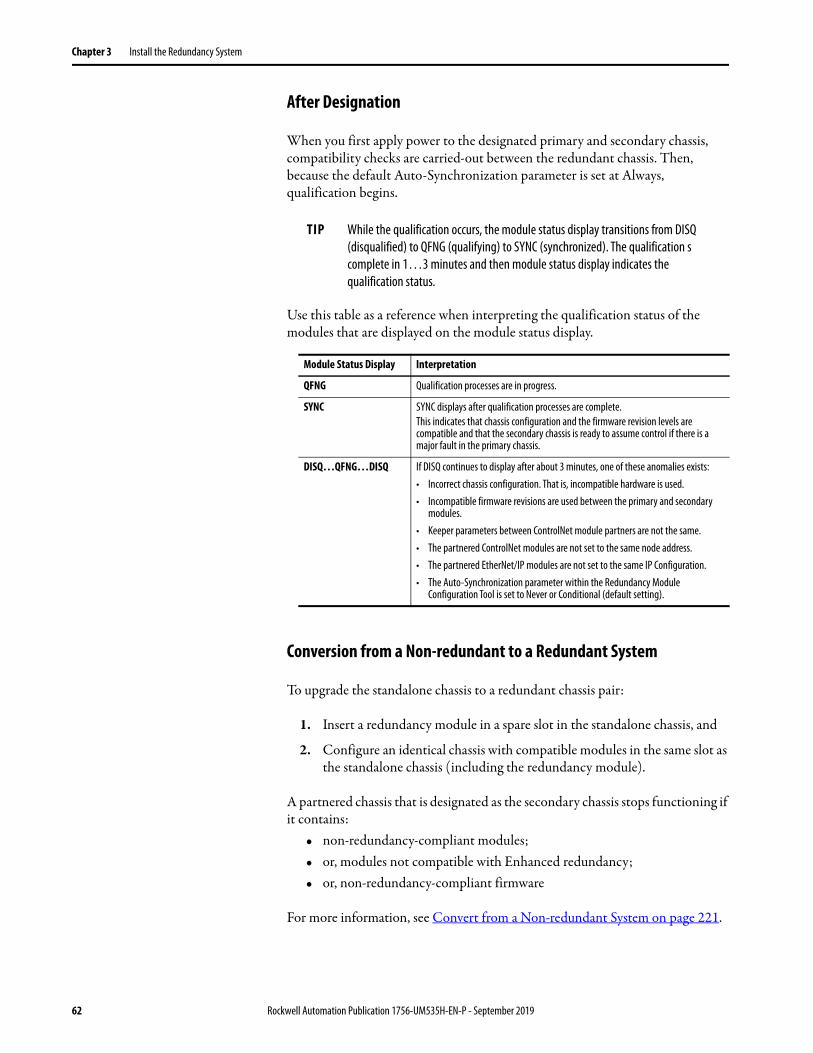
Chapter 3 Install the Redundancy System
After Designation
When you first apply power to the designated primary and secondary chassis, compatibility checks are carried-out between the redundant chassis. Then, because the default Auto-Synchronization parameter is set at Always, qualification begins.
Use this table as a reference when interpreting the qualification status of the modules that are displayed on the module status display.
Conversion from a Non-redundant to a Redundant System
To upgrade the standalone chassis to a redundant chassis pair:
1. Insert a redundancy module in a spare slot in the standalone chassis, and
2. Configure an identical chassis with compatible modules in the same slot as the standalone chassis (including the redundancy module).
A partnered chassis that is designated as the secondary chassis stops functioning if it contains:
• non-redundancy-compliant modules;• or, modules not compatible with Enhanced redundancy;• or, non-redundancy-compliant firmware
For more information, see Convert from a Non-redundant System on page 221.
TIP While the qualification occurs, the module status display transitions from DISQ (disqualified) to QFNG (qualifying) to SYNC (synchronized). The qualification s complete in 1…3 minutes and then module status display indicates the qualification status.
Module Status Display Interpretation
QFNG Qualification processes are in progress.
SYNC SYNC displays after qualification processes are complete.This indicates that chassis configuration and the firmware revision levels are compatible and that the secondary chassis is ready to assume control if there is a major fault in the primary chassis.
DISQ…QFNG…DISQ If DISQ continues to display after about 3 minutes, one of these anomalies exists:• Incorrect chassis configuration. That is, incompatible hardware is used.• Incompatible firmware revisions are used between the primary and secondary
modules.• Keeper parameters between ControlNet module partners are not the same.• The partnered ControlNet modules are not set to the same node address.• The partnered EtherNet/IP modules are not set to the same IP Configuration.• The Auto-Synchronization parameter within the Redundancy Module
Configuration Tool is set to Never or Conditional (default setting).
62 Rockwell Automation Publication 1756-UM535H-EN-P - September 2019
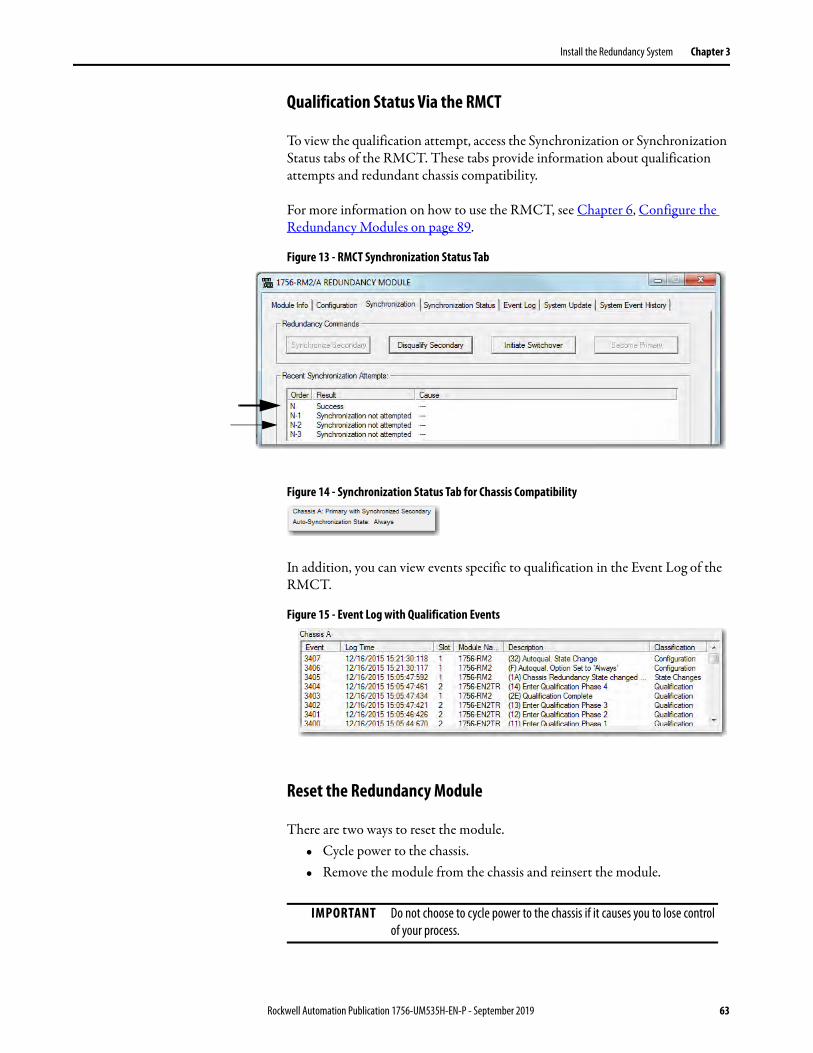
Install the Redundancy System Chapter 3
Qualification Status Via the RMCT
To view the qualification attempt, access the Synchronization or Synchronization Status tabs of the RMCT. These tabs provide information about qualification attempts and redundant chassis compatibility.
For more information on how to use the RMCT, see Chapter 6, Configure the Redundancy Modules on page 89.
Figure 13 - RMCT Synchronization Status Tab
Figure 14 - Synchronization Status Tab for Chassis Compatibility
In addition, you can view events specific to qualification in the Event Log of the RMCT.
Figure 15 - Event Log with Qualification Events
Reset the Redundancy Module
There are two ways to reset the module.• Cycle power to the chassis.• Remove the module from the chassis and reinsert the module.
IMPORTANT Do not choose to cycle power to the chassis if it causes you to lose control of your process.
Rockwell Automation Publication 1756-UM535H-EN-P - September 2019 63

Chapter 3 Install the Redundancy System
Remove or Replace the Redundancy Module
To remove or replace the redundancy module, follow these steps.
1. To disengage the upper and lower module tabs, push them.
2. Slide the module out of the chassis.
3. Insert the replacement in the same slot and move the fiber cable(s) to the new module.
IMPORTANT If you want to resume system operation with an identical module, you must install the new module in the same slot.
64 Rockwell Automation Publication 1756-UM535H-EN-P - September 2019
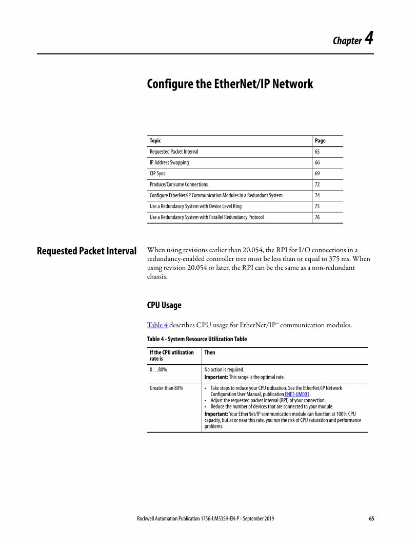
Chapter 4
Configure the EtherNet/IP Network
Requested Packet Interval When using revisions earlier than 20.054, the RPI for I/O connections in a redundancy-enabled controller tree must be less than or equal to 375 ms. When using revision 20.054 or later, the RPI can be the same as a non-redundant chassis.
CPU Usage
Table 4 describes CPU usage for EtherNet/IP™ communication modules.
Topic Page
Requested Packet Interval 65
IP Address Swapping 66
CIP Sync 69
Produce/Consume Connections 72
Configure EtherNet/IP Communication Modules in a Redundant System 74
Use a Redundancy System with Device Level Ring 75
Use a Redundancy System with Parallel Redundancy Protocol 76
Table 4 - System Resource Utilization Table
If the CPU utilization rate is
Then
0…80% No action is required.Important: This range is the optimal rate.
Greater than 80% • Take steps to reduce your CPU utilization. See the EtherNet/IP Network Configuration User Manual, publication ENET-UM001.
• Adjust the requested packet interval (RPI) of your connection.• Reduce the number of devices that are connected to your module.Important: Your EtherNet/IP communication module can function at 100% CPU capacity, but at or near this rate, you run the risk of CPU saturation and performance problems.
Rockwell Automation Publication 1756-UM535H-EN-P - September 2019 65
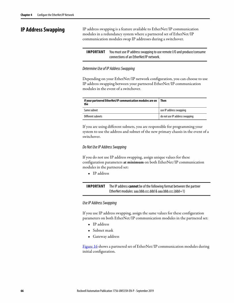
Chapter 4 Configure the EtherNet/IP Network
IP Address Swapping IP address swapping is a feature available to EtherNet/IP communication modules in a redundancy system where a partnered set of EtherNet/IP communication modules swap IP addresses during a switchover.
Determine Use of IP Address Swapping
Depending on your EtherNet/IP network configuration, you can choose to use IP address swapping between your partnered EtherNet/IP communication modules in the event of a switchover.
If you are using different subnets, you are responsible for programming your system to use the address and subnet of the new primary chassis in the event of a switchover.
Do Not Use IP Address Swapping
If you do not use IP address swapping, assign unique values for these configuration parameters at minimum on both EtherNet/IP communication modules in the partnered set:
• IP address
Use IP Address Swapping
If you use IP address swapping, assign the same values for these configuration parameters on both EtherNet/IP communication modules in the partnered set:
• IP address• Subnet mask• Gateway address
Figure 16 shows a partnered set of EtherNet/IP communication modules during initial configuration.
IMPORTANT You must use IP address swapping to use remote I/O and produce/consume connections of an EtherNet/IP network.
If your partnered EtherNet/IP communication modules are on the
Then
Same subnet use IP address swapping
Different subnets do not use IP address swapping
IMPORTANT The IP address cannot be of the following format between the partner EtherNet modules: aaa.bbb.ccc.ddd & aaa.bbb.ccc.(ddd+1)
66 Rockwell Automation Publication 1756-UM535H-EN-P - September 2019

Configure the EtherNet/IP Network Chapter 4
Figure 16 - IP Addresses of EtherNet/IP Communication Modules During System Configuration
When a redundancy system begins operating, the primary EtherNet/IP communication module uses the IP address that is assigned during initial configuration. The secondary EtherNet/IP communication module automatically changes its IP address to the next highest value. When a switchover occurs, the EtherNet/IP communication modules swap IP addresses.
For example, if you assign IP address 192.168.1.3 to both EtherNet/IP communication modules in a partnered set, on initial system operation, the secondary EtherNet/IP communication module automatically changes its IP address to 192.168.1.4.
Figure 17 shows a partnered set of EtherNet/IP communication modules after system operation begins.
Figure 17 - IP Addresses of EtherNet/IP Communication Modules After System Operation Begins
CH2 CH1 OK CH2 CH1 OK
Primary chassis Secondary Chassis
Assigned IP Address: 192.168.1.3
CH2 CH1 OK CH2 CH1 OK
Primary Chassis Secondary Chassis
IP Address: 192.168.1.3 IP Address: 192.168.1.4
Rockwell Automation Publication 1756-UM535H-EN-P - September 2019 67
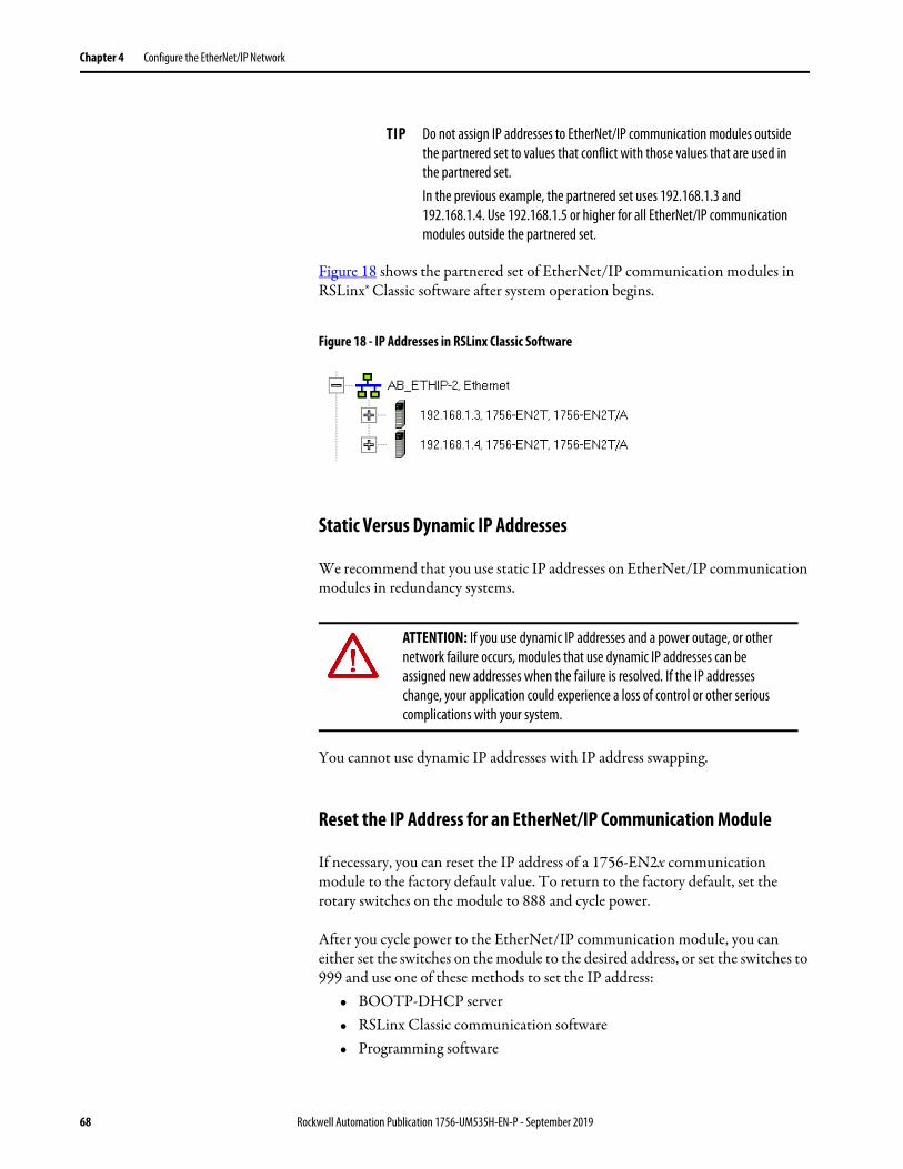
Chapter 4 Configure the EtherNet/IP Network
Figure 18 shows the partnered set of EtherNet/IP communication modules in RSLinx® Classic software after system operation begins.
Figure 18 - IP Addresses in RSLinx Classic Software
Static Versus Dynamic IP Addresses
We recommend that you use static IP addresses on EtherNet/IP communication modules in redundancy systems.
You cannot use dynamic IP addresses with IP address swapping.
Reset the IP Address for an EtherNet/IP Communication Module
If necessary, you can reset the IP address of a 1756-EN2x communication module to the factory default value. To return to the factory default, set the rotary switches on the module to 888 and cycle power.
After you cycle power to the EtherNet/IP communication module, you can either set the switches on the module to the desired address, or set the switches to 999 and use one of these methods to set the IP address:
• BOOTP-DHCP server• RSLinx Classic communication software• Programming software
TIP Do not assign IP addresses to EtherNet/IP communication modules outside the partnered set to values that conflict with those values that are used in the partnered set.In the previous example, the partnered set uses 192.168.1.3 and 192.168.1.4. Use 192.168.1.5 or higher for all EtherNet/IP communication modules outside the partnered set.
ATTENTION: If you use dynamic IP addresses and a power outage, or other network failure occurs, modules that use dynamic IP addresses can be assigned new addresses when the failure is resolved. If the IP addresses change, your application could experience a loss of control or other serious complications with your system.
68 Rockwell Automation Publication 1756-UM535H-EN-P - September 2019

Configure the EtherNet/IP Network Chapter 4
CIP Sync With redundancy system revision 19.052 or greater, you can use CIP Sync™ technology. CIP Sync technology provides a mechanism to synchronize clocks between controllers, I/O devices, and other automation products in your architecture with minimal user intervention.
CIP Sync technology uses Precision Time Protocol (PTP) to establish a Master/Slave relationship among the clocks for each CIP Sync-enabled component in the system. One master clock, which is known as the Grandmaster, sets the clock to which all other devices on the network synchronize their clocks.
Consider these points when you use CIP Sync technology in a redundancy system, revision 19.052 or later:
• If you enable CIP Sync Time Synchronization in the controllers in a redundant chassis pair, you must also enable Time Synchronization in the EtherNet/IP communication modules in the redundant chassis pair so all devices have one path to the Grandmaster. To enable Time Synchronization in the EtherNet/IP communication modules, change the Time Sync Connection from None (default) to Time Sync and Motion.
If time synchronization is enabled in any controller in the primary chassis of a disqualified redundant chassis pair, and no other devices in the primary chassis have time synchronization enabled, the redundant chassis pair attempts to qualify. However, in these application conditions, the attempt to qualify fails.
• While CIP Sync technology can handle multiple paths between master and slave clocks, it resolves mastership most effectively if you configure the redundant paths so that Time Synchronization is enabled in only the minimum required number of EtherNet/IP communication modules.
For example, if your redundant chassis pair has three 1756-EN2T communication modules and all are connected to the same network, enable Time Synchronization in only one of the modules.
IMPORTANT Before you use this enhancement in a redundancy system, revision 19.052 or later, see these publications for a full understanding of CIP Sync technology in any system:• Integrated Architecture™ and CIP Sync Configuration Application
Technique, publication IA-AT003• ControlLogix® System User Manual, publication 1756-UM001
Rockwell Automation Publication 1756-UM535H-EN-P - September 2019 69

Chapter 4 Configure the EtherNet/IP Network
• If the primary controller is the Grandmaster, the redundancy system automatically manages the CIP Sync clock attributes so that the controller in the primary chassis is always set to be the Grandmaster instead of the secondary controller. This clock management makes sure of a change to a new Grandmaster when the redundancy system switches over.
• When a switchover occurs, these events take place:
– The Grandmaster status transfers from the original primary controller to the new primary controller. This transfer can take longer to complete than if Grandmaster status was transferred between devices in a non-redundant system.
– After the switchover is complete, system synchronization can take longer in a redundancy system, revision 19.052 or later, which uses CIP™ technology than one that does not.
• If you attempt to use the Redundant System Update (RSU) feature to update a redundancy system, revision 16.081 or earlier, which uses Coordinated System Time (CST), the redundancy system, revision 19.052 or later, does not permit a locked switchover and the update fails to complete.
To work around this restriction, first disable CST Mastership in the original redundancy system and then use RSU to update the redundancy system to revision 19.052 or later.
70 Rockwell Automation Publication 1756-UM535H-EN-P - September 2019
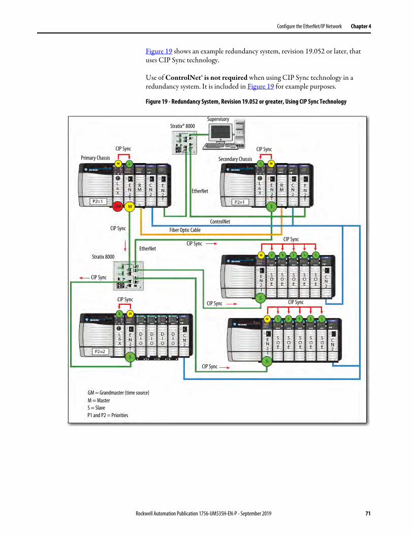
Configure the EtherNet/IP Network Chapter 4
Figure 19 shows an example redundancy system, revision 19.052 or later, that uses CIP Sync technology.
Use of ControlNet® is not required when using CIP Sync technology in a redundancy system. It is included in Figure 19 for example purposes.
Figure 19 - Redundancy System, Revision 19.052 or greater, Using CIP Sync Technology
Primary Chassis
CIP Sync
Stratix® 8000Supervisory
CIP Sync
Secondary Chassis
EtherNet
ControlNetCIP Sync
CIP Sync
CIP Sync
CIP Sync
CIP Sync CIP Sync
CIP Sync
CIP Sync
EtherNetStratix 8000
Fiber Optic Cable
GM = Grandmaster (time source)M = MasterS = SlaveP1 and P2 = Priorities
Rockwell Automation Publication 1756-UM535H-EN-P - September 2019 71

Chapter 4 Configure the EtherNet/IP Network
Produce/Consume Connections
With redundancy system revision 19.052 or later, you can use produce/consume connections over an EtherNet/IP network. Controllers let you produce (broadcast) and consume (receive) system-shared tags.
Figure 20 - Example System Using Produced and Consumed Tags
These requirements exist when you use produced and consumed connections over an EtherNet/IP network in a redundancy system, revision 19.052 or greater:
• You cannot bridge produced and consumed tags over two networks. For two controllers to share produced or consumed tags, both must be attached to the same network.
• Produced and consumed tags use connections in both the controllers and the communication modules being used.
• Because the use of produced and consumed tags uses connections, the number of connections available for other tasks, such as the exchange ofI/O data, is reduced.
The number of connections available in a system depends on controller type and network communication modules used. Closely track the number of produced and consumed connections to leave as many as necessary for other system tasks.
• You must configure both connections, that is, the connection between the primary controller and the remote controller, and the connection between the remote controller and the primary controller, for Multicast. However, if the redundancy system is the producer, it can be Unicast, because that is configured in the remote controller, which is allowed.
TIP When using ControlLogix 5570 controllers in your system, you must use revision 19.053 or greater.
CH2 CH1 OK CH2 CH1 OK
Primary Chassis Secondary Chassis
Controller 1 Produced Tag
Controller 2Consumed Tag
72 Rockwell Automation Publication 1756-UM535H-EN-P - September 2019

Configure the EtherNet/IP Network Chapter 4
Produced/Consumed Tags between Primary Controllers and Nonredundant Controllers
The connection from the remote controller to the redundant controller can briefly drop during a switchover. This condition can occur if the EtherNet/IP communication modules of the remote chassis do not use specific firmware revisions. The controllers in the redundant chassis pair must also produce tags over the EtherNet/IP network that the controllers in the remote chassis consume.
Use these firmware revisions for EtherNet/IP communication modules in the remote chassis to maintain connections during a switchover.
IMPORTANT Sockets are supported in the 1756-EN2T, 1756-EN2TR and 1756-EN2F modules, firmware revision 5.008 or later. For additional information, see the EtherNet/IP Socket Interface Application Technique, publication ENET-AT002.
IMPORTANT Unicast functionality in redundancy systems supports produced tags. Unicast consumed tags are not supported.
Table 5 - Minimum Firmware Revision for Communication Modules in Remote Chassis
EtherNet/IP Communication Module in Remote Chassis Minimum Firmware Revision
1756-EN2F 5.008 (unsigned)5.028 (signed)
1756-EN2T4.0021756-EN2TR
1756-EN3TR
1756-ENBT 6.001
1768-ENBT 4.001
1769-L2x19.011
1769-L3xE
1788-ENBT 3.001
IMPORTANT The minimum firmware revisions that are listed in Table 5 apply only to EtherNet/IP communication modules in the remote chassis. In a redundant chassis pair, you can use only the ControlLogix modules that are listed in the respective bundle's release notes
Rockwell Automation Publication 1756-UM535H-EN-P - September 2019 73

Chapter 4 Configure the EtherNet/IP Network
Configure EtherNet/IP Communication Modules in a Redundant System
Use these procedures to configure EtherNet/IP communication modules that are used in redundant chassis.
Before You Begin
Before you begin configuring the EtherNet/IP communication modules in the redundant chassis, verify that these tasks have been completed:
• The redundancy modules are installed and connected in the redundant chassis.
• A plan for IP address use has been executed:– If you are using IP address swapping, plan for the use of two
consecutive IP addresses in the partnered set.– If you are not using IP address swapping, plan for the use of two IP
addresses.• Know the subnet mask and gateway address for the Ethernet network the
redundant modules are to operate on.
Options for Setting the IP Addresses of EtherNet/IP Communication Modules
By default, ControlLogix EtherNet/IP communication modules ship with the IP address set to 999 and with Bootstrap Protocol (BOOTP)/Dynamic Host Configuration Protocol (DHCP)-enabled.
Use one of these tools to set the IP addresses for your EtherNet/IP communication modules:
• Rotary switches on the module• RSLinx Classic communication software• Programming software• BOOTP/DHCP utility
Half/Full Duplex Settings
The redundancy system uses the duplex settings of the EtherNet/IP communication module that is the primary. After a switchover, the duplex settings of the new primary EtherNet/IP communication module are used. By default, the duplex setting is automatic. We recommend that you use this setting whenever possible.
To avoid communication errors, configure both the primary and secondary EtherNet/IP communication modules with the same duplex settings. If you use different duplex settings on partnered EtherNet/IP communication modules, then messaging errors can occur after a switchover.
74 Rockwell Automation Publication 1756-UM535H-EN-P - September 2019

Configure the EtherNet/IP Network Chapter 4
Use a Redundancy System with Device Level Ring
Device Level Ring (DLR) is an EtherNet/IP protocol defined by the Open DeviceNet® Vendors’ Association (ODVA). DLR provides a means for detecting, managing, and recovering from single faults in a ring-based network.
A DLR network includes the following types of ring nodes.
Depending on their firmware capabilities, both devices and switches can operate as supervisors or ring nodes on a DLR network. Only switches can operate as redundant gateways.
For more information about DLR, see the EtherNet/IP Device Level Ring Application Technique, publication ENET-AT007.
Node Description
Ring supervisor A ring supervisor provides these functions:• Manages traffic on the DLR network• Collects diagnostic information for the networkA DLR network requires at least one node to be configured as ring supervisor.IMPORTANT: By default, the supervisor function is disabled on supervisor-capable devices, so they are ready to participate on a linear or star network or as a ring node on a DLR network.In a DLR network, you must configure at least one of the supervisor-capable devices as the ring supervisor before physically connecting the ring. If you do not, the DLR network does not work.We recommend to assign at least one supervisor outside of the redundant chassis pair to prevent losing supervision of the DLR during switchover.For more information on DLR operation see the EtherNet/IP Device Level Ring Application Technique, publication ENET-AT007.
Ring participants Ring participants provide these functions:• Process data that is transmitted over the network.• Pass on the data to the next node on the network.• Report fault locations to the active ring supervisor.When a fault occurs on the DLR network, ring participants reconfigure themselves and relearn the network topology.
Redundant gateways (optional)
Redundant gateways are multiple switches connected to a single DLR network and also connected together through the rest of the network.Redundant gateways provide DLR network resiliency to the rest of the network.
Rockwell Automation Publication 1756-UM535H-EN-P - September 2019 75

Chapter 4 Configure the EtherNet/IP Network
Use a Redundancy System with Parallel Redundancy Protocol
Parallel Redundancy Protocol (PRP) is defined in international standard IEC 62439-3 and provides high-availability in Ethernet networks. PRP technology creates seamless redundancy by sending duplicate frames to two independent network infrastructures, which are known as LAN A and LAN B.
A PRP network includes the following components.
For more information about PRP topologies and configuration guidelines, see the EtherNet/IP Parallel Redundancy Protocol Application Technique, publication ENET-AT006.
Component Description
LAN A and LAN B Redundant, active Ethernet networks that operate in parallel.
Double attached node (DAN) An end device with PRP technology that connects to both LAN A and LAN B.
Single attached node (SAN) An end device without PRP technology that connects to either LAN A or LAN B.A SAN does not have PRP redundancy.
Redundancy box (RedBox) A switch with PRP technology that connects devices without PRP technology to both LAN A and LAN B.
Virtual double attached node (VDAN)
An end device without PRP technology that connects to both LAN A and LAN B through a RedBox.A VDAN has PRP redundancy and appears to other nodes in the network as a DAN.
Infrastructure switch A switch that connects to either LAN A or LAN B and is not configured as a RedBox.
76 Rockwell Automation Publication 1756-UM535H-EN-P - September 2019
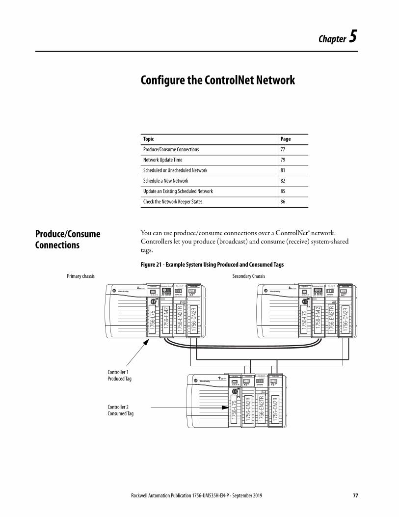
Chapter 5
Configure the ControlNet Network
Produce/Consume Connections
You can use produce/consume connections over a ControlNet® network. Controllers let you produce (broadcast) and consume (receive) system-shared tags.
Figure 21 - Example System Using Produced and Consumed Tags
Topic Page
Produce/Consume Connections 77
Network Update Time 79
Scheduled or Unscheduled Network 81
Schedule a New Network 82
Update an Existing Scheduled Network 85
Check the Network Keeper States 86
CH2 CH1 OK CH2 CH1 OK
Primary chassis Secondary Chassis
Controller 1 Produced Tag
Controller 2Consumed Tag
Rockwell Automation Publication 1756-UM535H-EN-P - September 2019 77

Chapter 5 Configure the ControlNet Network
Keep these points in mind when you use produced and consumed connections over a ControlNet network in a redundancy system:
• During a switchover, the connection for tags that are consumed from a redundant controller can drop briefly.
– The data does not update.– The logic acts on the last data that it received.
After the switchover, the connection is re-established and the data begins to update again.
• You cannot bridge produced and consumed tags over two networks. For two controllers to share produced or consumed tags, both must be attached to the same network.
• Produced and consumed tags use connections in both the controllers and the communication modules being used.
• Because the use of produced and consumed tags uses connections, the number of connections available for other tasks, such as the exchange ofI/O data, is reduced.
The number of connections available in a system depends on controller type and network communication modules used. Closely track the number of produced and consumed connections to leave as many as necessary for other system tasks.
78 Rockwell Automation Publication 1756-UM535H-EN-P - September 2019

Configure the ControlNet Network Chapter 5
Network Update Time The network update time (NUT) that you specify for your redundant system affects your system performance and your switchover response time. Typical NUTs used with redundant systems range from 5…10 ms.
NUTs with Multiple ControlNet Networks
You can choose to use multiple ControlNet networks with your redundancy system.
Figure 22 - Example of Two ControlNet Networks
When you use multiple ControlNet networks, the networks must use compatible NUTs. Compatible NUTs are determined based on the network that uses the smallest NUT.
CH2 CH1 OK CH2 CH1 OK
ControlNet Network 1
NUT = 5 msControlNet Network 2
NUT = ≤ 21 ms
Redundant Chassis Pair
Rockwell Automation Publication 1756-UM535H-EN-P - September 2019 79

Chapter 5 Configure the ControlNet Network
Use Table 6 to determine the compatible NUTs for your system.
Table 6 - Compatible NUT Values for Multiple ControlNet Networks
If the smallest NUT of a network is (ms)
Then the largest NUT of any other network must be less than or equal to (ms)
2 15
3 17
4 19
5 21
6 23
7 25
8 27
9 29
10 31
11 33
12 35
13 37
14 39
15 41
16 43
17 46
18 48
19 50
20 52
21 55
22 57
23 59
24 62
25 64
26 66
27 68
28 71
29 73
30 75
31 78
32 80
33 82
34 84
35 87
36 89
37…90 90
80 Rockwell Automation Publication 1756-UM535H-EN-P - September 2019

Configure the ControlNet Network Chapter 5
Scheduled or Unscheduled Network
It is up to you to if you want to use a scheduled or unscheduled network.
Use a Scheduled Network
Schedule or reschedule your ControlNet network when you execute these tasks:
• Commission a new redundant system.
• Add a chassis of remote ControlLogix® I/O that is set to use the Rack Optimized communication format.
• Add any remote I/O besides ControlLogix I/O. For example, if you add FLEX™ I/O modules, you must schedule the network.
• Use produced/consumed data. If you add a produced/consumed data tag, you must reschedule the ControlNet network.
To schedule or reschedule your ControlNet network, you put your redundant system in Program mode.
Use an Unscheduled Network
You can use an unscheduled network when you:
• Add a remote I/O chassis of ControlLogix I/O that does not use the Rack Optimized communication format. That is, direct connections to the I/O are used.
• Add a ControlLogix I/O module to a chassis that has already been scheduled and uses the Rack Optimized communication format.
• Add some drives that support adding I/O while online.
• Use ControlNet to monitor HMI or the controller program execution online.
You can add those components to the unscheduled network while your redundant system is online and in Run mode. We recommend that you do not use an unscheduled network for all of your I/O connections.
The use of 1756-CN2, 1756-CN2R, and 1756-CN2RXT modules provide increased capacity for adding I/O while online compared to 1756-CNB or 1756-CNBR modules. With this increased capacity, you can easily add I/O and increase ControlNet connections that are used without affecting your redundant system performance.
Rockwell Automation Publication 1756-UM535H-EN-P - September 2019 81
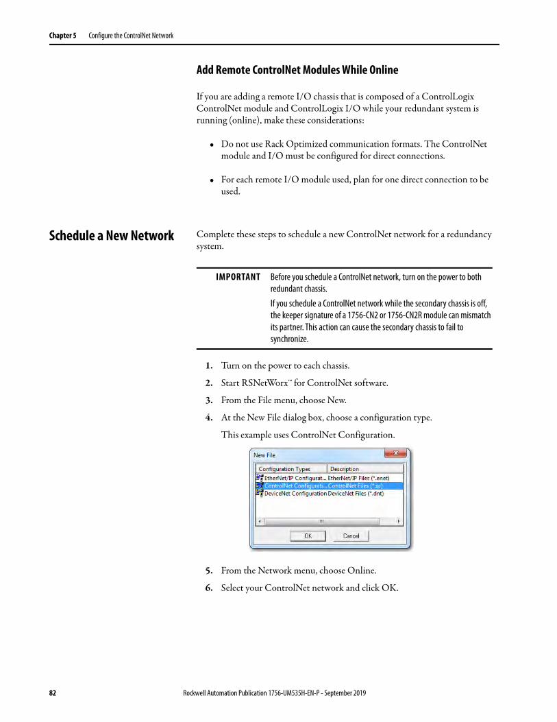
Chapter 5 Configure the ControlNet Network
Add Remote ControlNet Modules While Online
If you are adding a remote I/O chassis that is composed of a ControlLogix ControlNet module and ControlLogix I/O while your redundant system is running (online), make these considerations:
• Do not use Rack Optimized communication formats. The ControlNet module and I/O must be configured for direct connections.
• For each remote I/O module used, plan for one direct connection to be used.
Schedule a New Network Complete these steps to schedule a new ControlNet network for a redundancy system.
1. Turn on the power to each chassis.
2. Start RSNetWorx™ for ControlNet software.
3. From the File menu, choose New.
4. At the New File dialog box, choose a configuration type.
This example uses ControlNet Configuration.
5. From the Network menu, choose Online.
6. Select your ControlNet network and click OK.
IMPORTANT Before you schedule a ControlNet network, turn on the power to both redundant chassis.If you schedule a ControlNet network while the secondary chassis is off, the keeper signature of a 1756-CN2 or 1756-CN2R module can mismatch its partner. This action can cause the secondary chassis to fail to synchronize.
82 Rockwell Automation Publication 1756-UM535H-EN-P - September 2019
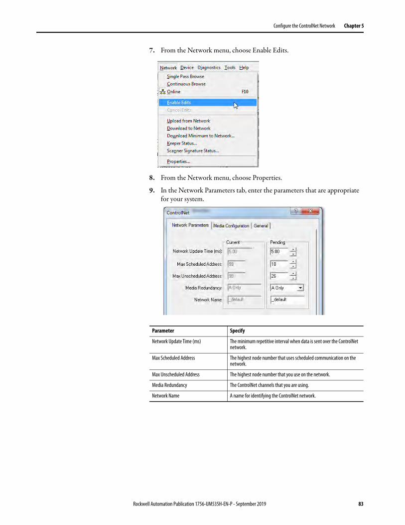
Configure the ControlNet Network Chapter 5
7. From the Network menu, choose Enable Edits.
8. From the Network menu, choose Properties.
9. In the Network Parameters tab, enter the parameters that are appropriate for your system.
Parameter Specify
Network Update Time (ms) The minimum repetitive interval when data is sent over the ControlNet network.
Max Scheduled Address The highest node number that uses scheduled communication on the network.
Max Unscheduled Address The highest node number that you use on the network.
Media Redundancy The ControlNet channels that you are using.
Network Name A name for identifying the ControlNet network.
Rockwell Automation Publication 1756-UM535H-EN-P - September 2019 83
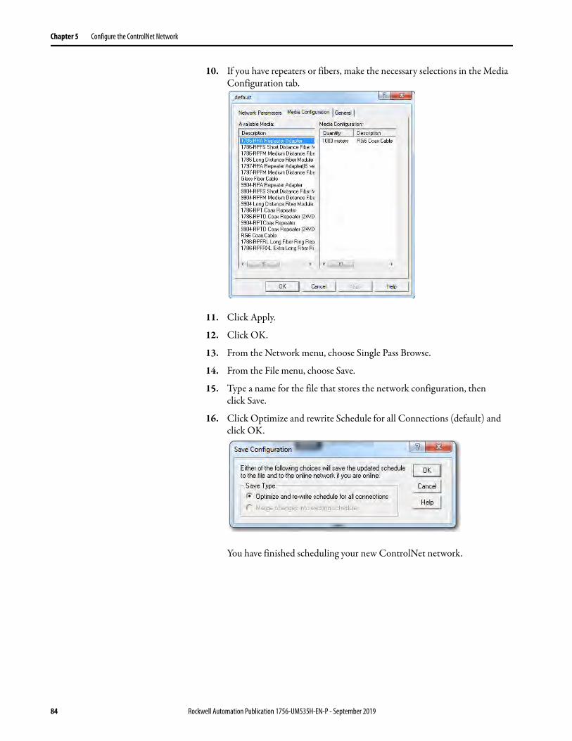
Chapter 5 Configure the ControlNet Network
10. If you have repeaters or fibers, make the necessary selections in the Media Configuration tab.
11. Click Apply.
12. Click OK.
13. From the Network menu, choose Single Pass Browse.
14. From the File menu, choose Save.
15. Type a name for the file that stores the network configuration, then click Save.
16. Click Optimize and rewrite Schedule for all Connections (default) and click OK.
You have finished scheduling your new ControlNet network.
84 Rockwell Automation Publication 1756-UM535H-EN-P - September 2019
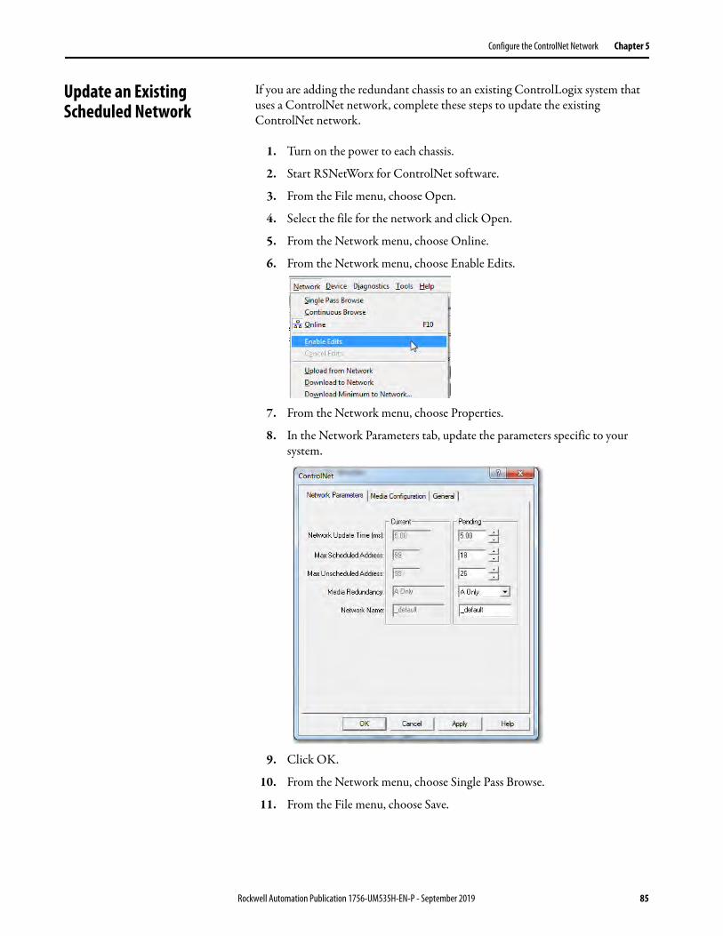
Configure the ControlNet Network Chapter 5
Update an Existing Scheduled Network
If you are adding the redundant chassis to an existing ControlLogix system that uses a ControlNet network, complete these steps to update the existing ControlNet network.
1. Turn on the power to each chassis.
2. Start RSNetWorx for ControlNet software.
3. From the File menu, choose Open.
4. Select the file for the network and click Open.
5. From the Network menu, choose Online.
6. From the Network menu, choose Enable Edits.
7. From the Network menu, choose Properties.
8. In the Network Parameters tab, update the parameters specific to your system.
9. Click OK.
10. From the Network menu, choose Single Pass Browse.
11. From the File menu, choose Save.
Rockwell Automation Publication 1756-UM535H-EN-P - September 2019 85
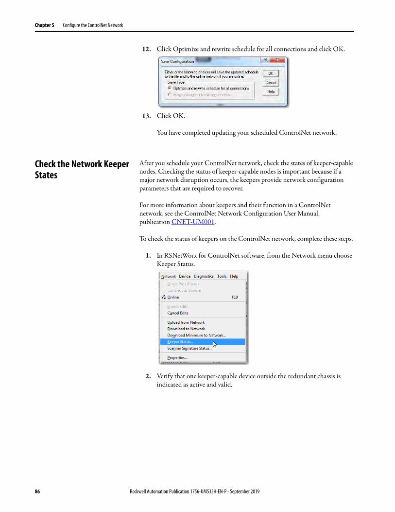
Chapter 5 Configure the ControlNet Network
12. Click Optimize and rewrite schedule for all connections and click OK.
13. Click OK.
You have completed updating your scheduled ControlNet network.
Check the Network Keeper States
After you schedule your ControlNet network, check the states of keeper-capable nodes. Checking the status of keeper-capable nodes is important because if a major network disruption occurs, the keepers provide network configuration parameters that are required to recover.
For more information about keepers and their function in a ControlNet network, see the ControlNet Network Configuration User Manual, publication CNET-UM001.
To check the status of keepers on the ControlNet network, complete these steps.
1. In RSNetWorx for ControlNet software, from the Network menu choose Keeper Status.
2. Verify that one keeper-capable device outside the redundant chassis is indicated as active and valid.
86 Rockwell Automation Publication 1756-UM535H-EN-P - September 2019

Configure the ControlNet Network Chapter 5
3. Verify that all keeper-capable devices on the network are valid.
4. Verify that all nodes on the network have the same keeper signature.
Active and valid keeper device.
Keeper-capable devices are valid.
Keeper signatures are the same.
TIP If the keeper signatures of partnered ControlNet modules are different, your redundant chassis can fail to synchronize.If the keeper signatures of your partnered ControlNet modules are different, update the keepers of the redundant ControlNet modules.
Rockwell Automation Publication 1756-UM535H-EN-P - September 2019 87

Chapter 5 Configure the ControlNet Network
Save the Project for Each Primary Controller
After you have scheduled your ControlNet networks, go online with each controller in your primary chassis and save the project. This process makes downloading a project easier in the future because you won’t be required to reschedule the network after completing the download.
Automatic Keeper Crossloads
The 1756-CN2, 1756-CN2R, and 1756-CN2RXT ControlNet modules have an Automatic Keeper Crossload feature that makes replacing a ControlNet module in a redundant chassis easier. The Automatic Keeper Crossload feature also reduces the need to use RSNetWorx for ControlNet software once the system is running.
With the Automatic Keeper Crossload feature, ControlNet modules can automatically upload the keeper signature and network parameters from the active keeper of a ControlNet network.
To replace a ControlNet module that has been configured and scheduled on the ControlNet network, remove the existing module and insert a 1756-CN2, 1756-CN2R, or 1756-CN2RXT module. The module that you are inserting must be unconfigured or have a keeper signature of all zeros.
After being inserted and connected to the ControlNet network, the unconfigured 1756-CN2, 1756-CN2R, and 1756-CN2RXT modules crossload the appropriate configuration from the active keeper on the ControlNet network. The modules then become configured with the appropriate keeper signature.
TIP To clear the keeper signature of a 1756-CN2, 1756-CN2R, or 1756-CN2RXT module, complete these steps.
1. Disconnect the module from the ControlNet network and remove it from the chassis.
2. Set the node address switches to 00.
3. Insert the module back into the chassis and wait for the status display to indicate Reset Complete.
4. Remove the module and set the node address switches to the intended node address.
5. Insert the module into the chassis.
88 Rockwell Automation Publication 1756-UM535H-EN-P - September 2019
Chapter 6
Configure the Redundancy Modules
About the Redundancy Module Configuration Tool (RMCT)
The Redundancy Module Configuration Tool (RMCT) is used to configure the redundancy modules and to determine the status of the redundancy system.
Use the RMCT to complete these configuration-related tasks:• Set Auto-Synchronization parameters.• Set the time and date of redundancy modules.• View and set module information.• View and set Chassis ID parameters (Chassis A, Chassis B).• Lock the redundant system for an update.• Conduct a test switchover.
You can also use this functionality available with the RMCT to determine the status of the redundant system:
• View error diagnostics specific to redundant chassis.• View qualification and compatibility status of partnered modules.• Identify noncompliant modules for removal.• View redundant system event history.
Topic Page
About the Redundancy Module Configuration Tool (RMCT) 89
Determine If Further Configuration Is Required 90
Use the RMCT 91
Module Info Tab 94
Configuration Tab 97
Synchronization Tab 100
Synchronization Status Tab 103
System Update Tab 104
Rockwell Automation Publication 1756-UM535H-EN-P - September 2019 89
Chapter 6 Configure the Redundancy Modules
Determine If Further Configuration Is Required
The default configuration of the redundancy modules lets you synchronize your redundant chassis without additional configuration if you are using a basic redundant chassis pair.
However, some applications and uses of the redundancy system can require additional configuration. For example, you must use the RMCT for additional configuration if you must complete any of these tasks:
• Set the redundancy modules to another time or date (recommended).• Program your controller to control the redundant system.• Change the redundancy synchronization options of the redundant system.• Change the synchronization states of your redundant chassis.• Conduct a test switchover.• Complete a firmware update of a module in the redundant chassis while
the system is online.
If you must complete any of these tasks, see the sections that follow.
90 Rockwell Automation Publication 1756-UM535H-EN-P - September 2019
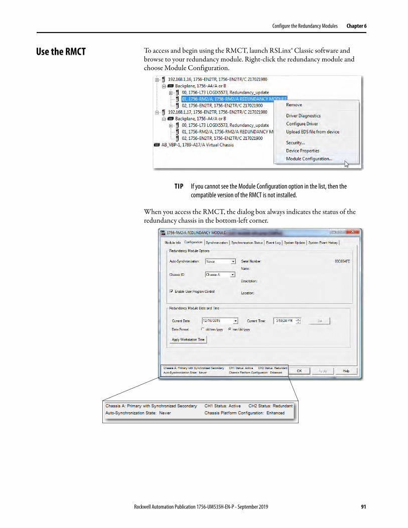
Configure the Redundancy Modules Chapter 6
Use the RMCT To access and begin using the RMCT, launch RSLinx® Classic software and browse to your redundancy module. Right-click the redundancy module and choose Module Configuration.
When you access the RMCT, the dialog box always indicates the status of the redundancy chassis in the bottom-left corner.
TIP If you cannot see the Module Configuration option in the list, then the compatible version of the RMCT is not installed.
Rockwell Automation Publication 1756-UM535H-EN-P - September 2019 91

Chapter 6 Configure the Redundancy Modules
Identify the RMCT Version
You must use a version of the RMCT that is compatible with your redundancy module firmware.
Beginning with version 20.054, the redundancy module firmware reports back to the Redundancy Module Configuration Tool (RMCT) as to which version of the RMCT is compatible. If there is an incompatibility, the RMCT shows only the Module Info tab and indicates the version that the firmware is compatible with.
For more information on the RMCT compatibility, see Knowledgebase article 29511.
To find the latest firmware bundle on the website, follow these steps.
1. The Redundancy Module Configuration Tool (RMCT) can be downloaded from the Product Compatibility and Download Center under the Firmware Downloads.
2. Search by the redundancy bundle used with your system to locate the proper RMCT. The bundle is named by the firmware that is on the processor in the redundancy system.
3. Depending on the version of the bundle, the RMCT may be included with the firmware bundle or separate:
92 Rockwell Automation Publication 1756-UM535H-EN-P - September 2019

Configure the Redundancy Modules Chapter 6
Complete these steps to check or verify the version of the Redundancy Module Configuration Tool (RMCT) that you have installed.
1. Launch RSLinx Classic software.
2. Click the RSWho icon.
3. Right-click your redundancy module and choose Module Configuration.
The Module Configuration dialog box opens.
4. Right-click the title bar and choose About.
The About dialog box opens and indicates the RMCT version.
TIP The RMCT launches at the version that is compatible with the 1756 redundancy module firmware that is installed.If you have not updated your 1756 redundancy module firmware after upgrading your RMCT version, the RMCT version that is indicated can differ from version you updated to. You can also check the RMCT version that you have installed by using Add or Remove Programs in the Control Panel.
Rockwell Automation Publication 1756-UM535H-EN-P - September 2019 93

Chapter 6 Configure the Redundancy Modules
This should show the version you need based on your bundle or higher. The RMCT always shows the latest version installed, and later versions are backwards compatible with earlier versions.
Update the RMCT Version
The RMCT version that is compatible with your redundancy module firmware is included in the downloads for most redundancy bundles.
• For redundancy bundles that use firmware revision 20.009 or later for 1756-RM2 modules, the RMCT is included in the redundancy bundle and is not available for separate download.
• For redundancy bundles that use firmware revision earlier than 20.009, you can download the RMCT separately as a product add-on.
To launch the installation of the RMCT, open the folder that contains the redundancy firmware revision and double-click the executable file titled Redundancy_Module_CT.exe.
The RMCT Installation Wizard opens and prompts you with the steps to install the RMCT.
Module Info Tab The Module Info tab of the RMCT provides a general overview of the identification and status information of the redundancy module. This status information is updated approximately once every two seconds.
94 Rockwell Automation Publication 1756-UM535H-EN-P - September 2019

Configure the Redundancy Modules Chapter 6
TIP Not all indicators are shown for 1756-RM/A and 1756-RM/B modules.
Rockwell Automation Publication 1756-UM535H-EN-P - September 2019 95
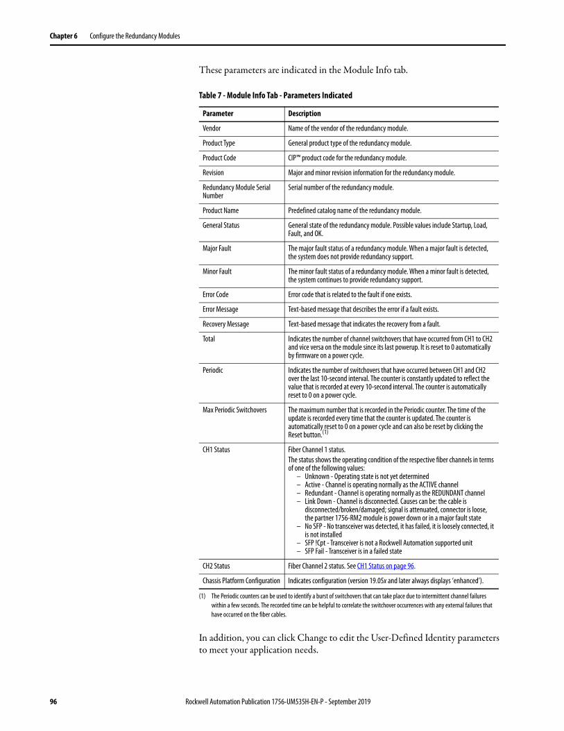
Chapter 6 Configure the Redundancy Modules
These parameters are indicated in the Module Info tab.
In addition, you can click Change to edit the User-Defined Identity parameters to meet your application needs.
Table 7 - Module Info Tab - Parameters Indicated
Parameter Description
Vendor Name of the vendor of the redundancy module.
Product Type General product type of the redundancy module.
Product Code CIP™ product code for the redundancy module.
Revision Major and minor revision information for the redundancy module.
Redundancy Module Serial Number
Serial number of the redundancy module.
Product Name Predefined catalog name of the redundancy module.
General Status General state of the redundancy module. Possible values include Startup, Load, Fault, and OK.
Major Fault The major fault status of a redundancy module. When a major fault is detected, the system does not provide redundancy support.
Minor Fault The minor fault status of a redundancy module. When a minor fault is detected, the system continues to provide redundancy support.
Error Code Error code that is related to the fault if one exists.
Error Message Text-based message that describes the error if a fault exists.
Recovery Message Text-based message that indicates the recovery from a fault.
Total Indicates the number of channel switchovers that have occurred from CH1 to CH2 and vice versa on the module since its last powerup. It is reset to 0 automatically by firmware on a power cycle.
Periodic Indicates the number of switchovers that have occurred between CH1 and CH2 over the last 10-second interval. The counter is constantly updated to reflect the value that is recorded at every 10-second interval. The counter is automatically reset to 0 on a power cycle.
Max Periodic Switchovers The maximum number that is recorded in the Periodic counter. The time of the update is recorded every time that the counter is updated. The counter is automatically reset to 0 on a power cycle and can also be reset by clicking the Reset button.(1)
(1) The Periodic counters can be used to identify a burst of switchovers that can take place due to intermittent channel failures within a few seconds. The recorded time can be helpful to correlate the switchover occurrences with any external failures that have occurred on the fiber cables.
CH1 Status Fiber Channel 1 status.The status shows the operating condition of the respective fiber channels in terms of one of the following values:
– Unknown - Operating state is not yet determined– Active - Channel is operating normally as the ACTIVE channel– Redundant - Channel is operating normally as the REDUNDANT channel– Link Down - Channel is disconnected. Causes can be: the cable is
disconnected/broken/damaged; signal is attenuated, connector is loose, the partner 1756-RM2 module is power down or in a major fault state
– No SFP - No transceiver was detected, it has failed, it is loosely connected, it is not installed
– SFP !Cpt - Transceiver is not a Rockwell Automation supported unit– SFP Fail - Transceiver is in a failed state
CH2 Status Fiber Channel 2 status. See CH1 Status on page 96.
Chassis Platform Configuration Indicates configuration (version 19.05x and later always displays ‘enhanced’).
96 Rockwell Automation Publication 1756-UM535H-EN-P - September 2019
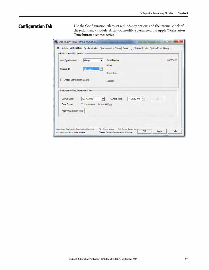
Configure the Redundancy Modules Chapter 6
Configuration Tab Use the Configuration tab to set redundancy options and the internal clock of the redundancy module. After you modify a parameter, the Apply Workstation Time button becomes active.
Rockwell Automation Publication 1756-UM535H-EN-P - September 2019 97

Chapter 6 Configure the Redundancy Modules
Auto-synchronization
The first parameter in the Configuration tab is the Auto-Synchronization parameter. The value that you chose for this parameter determines a significant part of your redundant system behavior.
Use the following table to determine the Auto-Synchronization setting that best suits your application.
TIP Verify that your Auto-Synchronization parameter is at the proper value before you modify your redundant system. This verification helps prevent system errors.For example, if you are upgrading your redundant system firmware, verify that this parameter is set to Never or Conditional before disqualifying your secondary chassis. If this parameter is Always, you cannot properly disqualify your chassis and conduct the update.
If you use this parameter This synchronization behavior results
Never The system remains in the same state, that is, either synchronized or disqualified, until one of these events takes place:• A command is issued from the RMCT to either synchronize or disqualify.• The controller commands synchronization or disqualification by using a
MSG instruction. For this action to occur, Enable User Program Control must be checked.
• A fault on the primary causes a switchover.
Always The system automatically synchronizes regularly. If you attempt to disqualify the system by using the Disqualify Secondary command in the RMCT, the resulting disqualification is temporary as the system automatically qualifies and synchronizes again.If the controller program disqualifies the system, the resulting disqualification is also temporary.
Conditional The system behavior with this setting is dependent on the Auto-Synchronization state of your system, found in the lower left portion of the RMCT window after setting the Auto-Synchronization parameter to Conditional:• If your Auto-Synchronization parameter is set to Conditional and your
Auto-Synchronization state is 'Conditional, Enabled', then the system continually attempts to synchronize.
• If your Auto-Synchronization parameter is set to Conditional and your Auto-Synchronization state is 'Conditional, Disabled', then the system does not automatically attempt to synchronize.
To change from 'Conditional, Enabled' to 'Conditional, Disabled', click Disqualify Secondary on the Synchronization tab.To change from 'Conditional, Disabled' to 'Conditional, Enabled', click Synchronize Secondary on the Synchronization tab.
98 Rockwell Automation Publication 1756-UM535H-EN-P - September 2019

Configure the Redundancy Modules Chapter 6
Chassis ID
The chassis ID parameter is used to assign a generic label to the chassis that house the redundancy modules. The available chassis labels are Chassis A and Chassis B.
If you change the chassis label in the RMCT of the primary redundancy module, the secondary module and chassis are automatically assigned the other chassis label.
The chassis label that is assigned to the module remains associated with the same physical chassis, regardless of its primary or secondary control designation.
Enable User Program Control
Check Enable User Program Control in the Configuration tab if you plan to use MSG instructions in your controller program to initiate a switchover, change the redundancy module time, or synchronize.
If you leave Enable User Program Control unchecked, the redundancy modules do not accept any commands from the controller.
Redundancy Module Date and Time
The Redundancy Module Date and Time parameters can be applied separate from the Redundancy Module Options parameters. The time that is specified with these parameters is the time that the event logs reference when a redundant system event occurs.
To change the redundancy module time settings, use the pull-down menu or type your changes then click Set to implement time changes. Or, to set the time of the redundancy module to match that of the workstation, click Apply Workstation Time.
IMPORTANT We recommend that you set the redundancy module date and time when you commission a system. We also recommend that you periodically check the date and time settings to make sure that they match the settings of the controller.If a power failure occurs on the redundant chassis, you must reset the date and time information of the redundancy modules. The modules do not retain those parameters when power is lost.
Rockwell Automation Publication 1756-UM535H-EN-P - September 2019 99

Chapter 6 Configure the Redundancy Modules
Synchronization Tab The Synchronization Tab has commands for these options:• Change the synchronization state of the system (synchronize or disqualify)• Initiate a switchover• Force the disqualified secondary to become the primary
The commands are described in the Commands in the Synchronization Tab section on page 101.
This tab also has information about the last four synchronization attempts in the Recent Synchronization Attempts log. N or N-X identify synchronization attempts in the log. If the redundant chassis fail to synchronize, a cause is identified in the Recent Synchronization Attempts log.
The causes and their interpretations are described in the Recent Synchronization Attempts Log section on page 102.
100 Rockwell Automation Publication 1756-UM535H-EN-P - September 2019
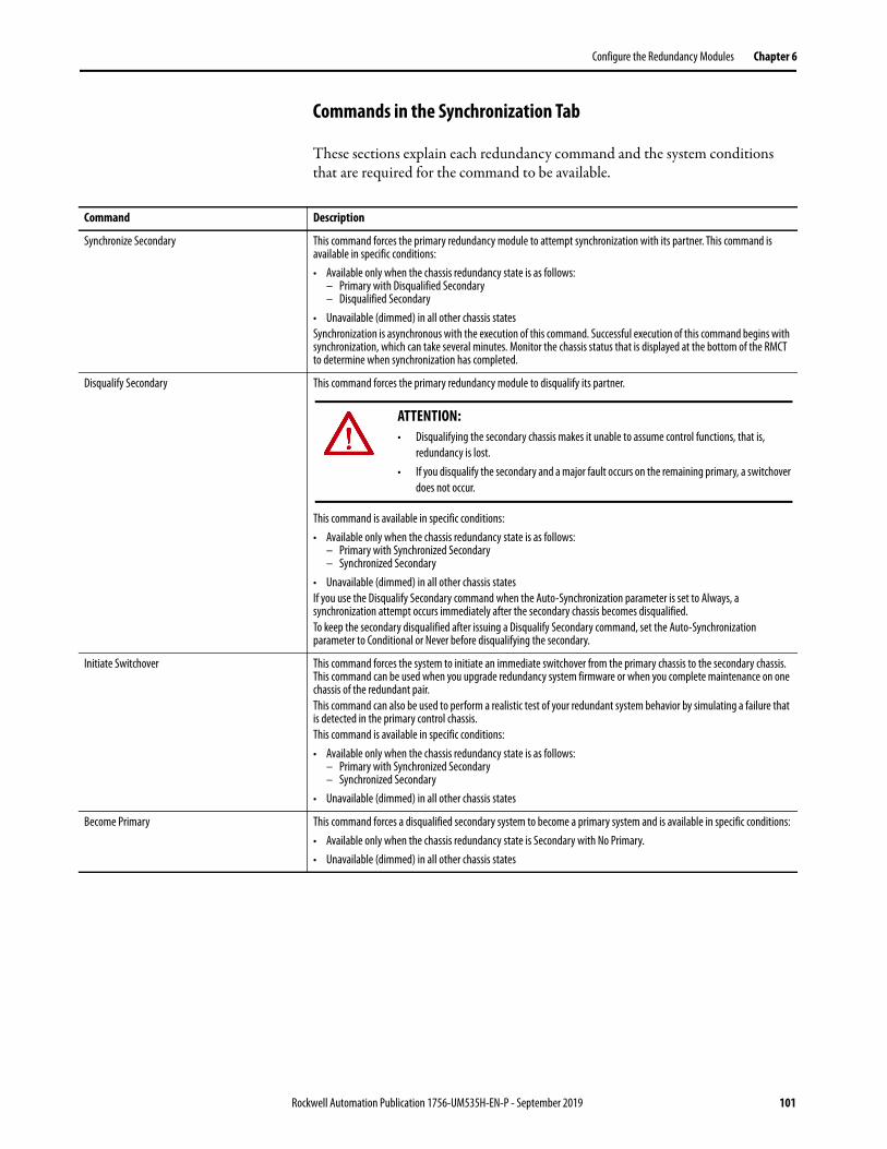
Configure the Redundancy Modules Chapter 6
Commands in the Synchronization Tab
These sections explain each redundancy command and the system conditions that are required for the command to be available.
Command Description
Synchronize Secondary This command forces the primary redundancy module to attempt synchronization with its partner. This command is available in specific conditions:• Available only when the chassis redundancy state is as follows:
– Primary with Disqualified Secondary– Disqualified Secondary
• Unavailable (dimmed) in all other chassis statesSynchronization is asynchronous with the execution of this command. Successful execution of this command begins with synchronization, which can take several minutes. Monitor the chassis status that is displayed at the bottom of the RMCT to determine when synchronization has completed.
Disqualify Secondary This command forces the primary redundancy module to disqualify its partner.
This command is available in specific conditions:• Available only when the chassis redundancy state is as follows:
– Primary with Synchronized Secondary– Synchronized Secondary
• Unavailable (dimmed) in all other chassis statesIf you use the Disqualify Secondary command when the Auto-Synchronization parameter is set to Always, a synchronization attempt occurs immediately after the secondary chassis becomes disqualified.To keep the secondary disqualified after issuing a Disqualify Secondary command, set the Auto-Synchronization parameter to Conditional or Never before disqualifying the secondary.
Initiate Switchover This command forces the system to initiate an immediate switchover from the primary chassis to the secondary chassis. This command can be used when you upgrade redundancy system firmware or when you complete maintenance on one chassis of the redundant pair.This command can also be used to perform a realistic test of your redundant system behavior by simulating a failure that is detected in the primary control chassis.This command is available in specific conditions:• Available only when the chassis redundancy state is as follows:
– Primary with Synchronized Secondary– Synchronized Secondary
• Unavailable (dimmed) in all other chassis states
Become Primary This command forces a disqualified secondary system to become a primary system and is available in specific conditions:• Available only when the chassis redundancy state is Secondary with No Primary.• Unavailable (dimmed) in all other chassis states
ATTENTION: • Disqualifying the secondary chassis makes it unable to assume control functions, that is,
redundancy is lost.• If you disqualify the secondary and a major fault occurs on the remaining primary, a switchover
does not occur.
Rockwell Automation Publication 1756-UM535H-EN-P - September 2019 101

Chapter 6 Configure the Redundancy Modules
Recent Synchronization Attempts Log
This table describes the possible result and causes of synchronization states.
If the Synchronization Attempts log indicates that the Synchronization attempt was aborted, use Table 9 to diagnose the cause.
Table 8 - Recent Synchronization Attempts Log - Result Interpretations
Result Result Interpretation
Undefined The result of the synchronization is unknown.
No attempt since last powerup Synchronization has not been attempted since power was applied to the module.
Success Full synchronization was successfully completed.
Abort The synchronization attempt failed. See Table 9 for further information.
Table 9 - Synchronization Interpretation
Cause Cause Interpretation
Undefined The cause of synchronization failure is unknown.
Module Pair Incompatible Synchronization was aborted because one or more module pairs are incompatible.
Module Configuration Error Synchronization was aborted because one of the modules is improperly configured.
Edit Session In Progress Synchronization was aborted because an edit or session is in progress.
Crossloading Failure An undetermined failure occurred during synchronization between redundancy modules.
Comm Disconnected The cable between the redundancy modules was disconnected.
Module Insertion Synchronization was aborted because a module was inserted into a chassis.
Module Removal Synchronization was aborted because a module was removed from a chassis.
Secondary Module Failed Synchronization was aborted because of a failure in the secondary module.
Incorrect Chassis State Synchronization was aborted due to an incorrect chassis state.
Comm Does Not Exist Synchronization could not be performed because the communication link between redundancy modules does not exist.
Non-redundant Compliant Module Exists Synchronization could not be performed because one or more non-redundancy modules are present in one of the chassis.
Sec Failed Module Exists A module in the secondary chassis has asserted the SYS_FAIL line, which indicates that it has faulted or failed.
Local Major Unrecoverable Fault Synchronization was aborted because of a local major unrecoverable fault.
Partner Has Major Fault Synchronization was aborted because the partner module has a major fault.
Sec SYS_FAIL_L Subsystem Failed The test of the SYS_FAIL line in the secondary chassis failed.
Sec RM Device Status = Comm Error Synchronization was aborted because the status of the secondary redundancy module indicates a communication error.
Sec RM Device Status = Major Recoverable Fault
Synchronization was aborted because the status of the secondary redundancy module indicates a major recoverable fault.
Sec RM Device Status = Major Unrecoverable Fault
Synchronization was aborted because the status of the secondary redundancy module indicates a major unrecoverable fault.
Incorrect Device State Synchronization was aborted because the device is in the wrong state.
Primary Module Failed Synchronization was aborted because of a failure in the primary module.
Primary Failed Module Exists A module in the primary chassis has asserted the SYS_FAIL line, which indicates that it has faulted or failed.
Auto-Sync Option Synchronization was aborted because the Auto-Synchronization parameter of one of the redundancy modules was changed during synchronization.
102 Rockwell Automation Publication 1756-UM535H-EN-P - September 2019

Configure the Redundancy Modules Chapter 6
Synchronization Status Tab The Synchronization Status tab provides a module-level view of these items:
• Synchronization state (for example, Synchronized or Disqualified)
• Chassis designation (Primary or Secondary)
• Module compatibility with its partner (for example, Full or Undefined)
Each module that is installed in the chassis is identified and information regarding its partner and compatibility are provided.
Module Qual Request Synchronization was aborted because another synchronization request was received. The current synchronization has stopped so that the new synchronization request can be serviced.
SYS_FAIL_L Deasserted Synchronization was aborted because one of the modules came out of a faulted or failed state.
Disqualify Command Synchronization was aborted because the redundancy module received a disqualify command from another device. The originating device sends this command when it can no longer perform in the qualified state.
Disqualify Request Synchronization was aborted because the redundancy module received a disqualify command from another device. The originating device sends this command when it can no longer perform in the qualified state.
Platform Configuration Identity Mismatch Detected
There are modules in the primary or secondary chassis that do not belong to the platform.
Application Requires Enhanced Platform A redundant controller is running an application that contains a feature that is qualified to run only on an enhanced redundant platform, for example, Alarms.
ICPT Asserted A test line on the backplane is asserted.
Unicast Not Supported A unicast connection is configured in the redundant controller, and redundancy systems do not support Unicast.
PTP Configuration Error The PTP clock of a redundant controller is not synchronized or the partner controller pair is synchronized to another Grandmaster.
Secured Module Mismatch A mismatch was detected between a primary and secondary secured module.
Table 9 - Synchronization Interpretation
Cause Cause Interpretation
Synchronization State Chassis Designation Module-partner Compatibility
Rockwell Automation Publication 1756-UM535H-EN-P - September 2019 103

Chapter 6 Configure the Redundancy Modules
System Update Tab Use of the commands in the System Update tab lets you perform firmware updates in the secondary chassis while the primary chassis remains in control. Reference the lock and switchover logs in this tab for update information when completing a firmware update.
ATTENTION: When performing firmware updates by using commands in the System Update tab, redundancy is lost. In the event of a fault on the operating primary chassis, the system cannot switch control to the secondary chassis.
104 Rockwell Automation Publication 1756-UM535H-EN-P - September 2019

Configure the Redundancy Modules Chapter 6
System Update Commands
The three system update commands are available only when accessing a primary redundancy module. These commands are not available when accessing the secondary redundancy module.
Lock For Update
The Lock for Update command lets you synchronize a redundant chassis pair under these conditions:
• The secondary redundancy module uses updated firmware and an updated programming software application program version.
• The running primary redundancy module uses a previous firmware revision and previous programming software application program version.
The Lock for Update command is available only when all modules in the primary chassis have no compatibility anomalies. Before issuing the lock command, verify that you have completed these tasks:
• Set the Auto-Synchronization option in the Configuration tab to Never.
• Disqualify the secondary chassis by using the Disqualify Secondary command in the Synchronization tab of the RMCT of the secondary redundancy module.
• Updated the primary and secondary redundancy modules to compatible firmware revisions.
• Updated all other modules in the secondary chassis to their intended firmware revisions.
• Configured the controller project that as required to accommodate the update and replacement of modules if needed.
For details about how to complete those tasks, see Update Redundant Firmware on page 58.
TIP While you are completing tasks to update the system by using the system update commands, you cannot access these tabs in the RMCT:• Configuration• Synchronization• Synchronization StatusIf you attempt to access any of these tabs while the system is locked or is completing a locked switchover, it results in an error dialog box.
Rockwell Automation Publication 1756-UM535H-EN-P - September 2019 105
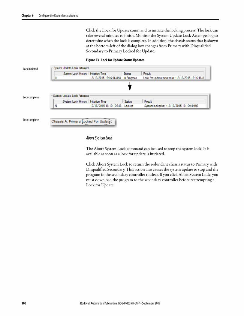
Chapter 6 Configure the Redundancy Modules
Click the Lock for Update command to initiate the locking process. The lock can take several minutes to finish. Monitor the System Update Lock Attempts log to determine when the lock is complete. In addition, the chassis status that is shown at the bottom-left of the dialog box changes from Primary with Disqualified Secondary to Primary Locked for Update.
Figure 23 - Lock for Update Status Updates
Abort System Lock
The Abort System Lock command can be used to stop the system lock. It is available as soon as a lock for update is initiated.
Click Abort System Lock to return the redundant chassis status to Primary with Disqualified Secondary. This action also causes the system update to stop and the program in the secondary controller to clear. If you click Abort System Lock, you must download the program to the secondary controller before reattempting a Lock for Update.
Lock initiated.
Lock complete.
Lock complete.
106 Rockwell Automation Publication 1756-UM535H-EN-P - September 2019

Configure the Redundancy Modules Chapter 6
Initiate Locked Switchover
The Initiate Locked Switchover command is available only when the chassis redundancy state is Primary with Locked Secondary. That is, the Initiate Locked Switchover is available only after the lock for update is complete.
If you click Initiate Locked Switchover, your secondary chassis assumes control and becomes the new primary. The old primary is now the new secondary chassis and you can update the firmware of the modules in the new secondary chassis.
Figure 24 - Illustration of Switchover
The difference between a locked switchover and a normal switchover is that you initiate the locked switchover. You or a fault in the primary chassis initiate a normal switchover.
CH2 CH1 OK CH2 CH1 OK
CH2 CH1 OKCH2 CH1 OK
Chassis A
Chassis A
Chassis B
Chassis B
Prim
ary
Prim
ary
Seco
ndar
ySe
cond
ary
Rockwell Automation Publication 1756-UM535H-EN-P - September 2019 107
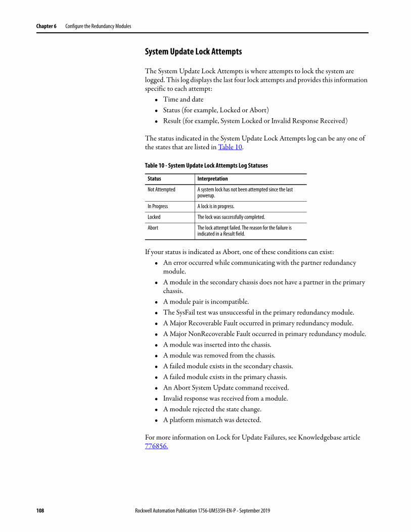
Chapter 6 Configure the Redundancy Modules
System Update Lock Attempts
The System Update Lock Attempts is where attempts to lock the system are logged. This log displays the last four lock attempts and provides this information specific to each attempt:
• Time and date• Status (for example, Locked or Abort)• Result (for example, System Locked or Invalid Response Received)
The status indicated in the System Update Lock Attempts log can be any one of the states that are listed in Table 10.
If your status is indicated as Abort, one of these conditions can exist:• An error occurred while communicating with the partner redundancy
module.• A module in the secondary chassis does not have a partner in the primary
chassis.• A module pair is incompatible.• The SysFail test was unsuccessful in the primary redundancy module.• A Major Recoverable Fault occurred in primary redundancy module.• A Major NonRecoverable Fault occurred in primary redundancy module.• A module was inserted into the chassis.• A module was removed from the chassis.• A failed module exists in the secondary chassis.• A failed module exists in the primary chassis.• An Abort System Update command received.• Invalid response was received from a module.• A module rejected the state change.• A platform mismatch was detected.
For more information on Lock for Update Failures, see Knowledgebase article 776856.
Table 10 - System Update Lock Attempts Log Statuses
Status Interpretation
Not Attempted A system lock has not been attempted since the last powerup.
In Progress A lock is in progress.
Locked The lock was successfully completed.
Abort The lock attempt failed. The reason for the failure is indicated in a Result field.
108 Rockwell Automation Publication 1756-UM535H-EN-P - September 2019

Configure the Redundancy Modules Chapter 6
Locked Switchover Attempts
The Locked Switchover Attempts log provides information about the status of the last four locked switchover attempts. This log includes this information about each attempt:
• Time and date• Status• Result
The status indicated in the Locked Switchover Attempts log can be any one of the states that are listed in Table 11.
If a locked switchover is aborted, it can be because of the following:• A module declined a locked switchover readiness request.• An invalid response was received from the locked switchover readiness
request.• After an initiate switchover prompt, a module rejected the command.• After an initiate switchover prompt, a module replied with an invalid
response.
Table 11 - Locked Switchover Event Log Statuses
Status Description
Not Attempted A locked switchover has not been attempted since the last powerup.
In Progress A locked switchover is in progress.
Success A locked switchover was successfully completed.
Abort The locked switchover attempt failed. The cause of the failure is indicated in a Result field.
Rockwell Automation Publication 1756-UM535H-EN-P - September 2019 109

Chapter 6 Configure the Redundancy Modules
Notes:
110 Rockwell Automation Publication 1756-UM535H-EN-P - September 2019
Chapter 7
Program the Redundant Controller
Topic Page
Configure the Redundant Controller 112
Crossloads, Synchronization, and Switchovers 116
Crossloads and Scan Time 121
Program to Minimize Scan Times 123
Program to Maintain Data Integrity 130
Program to Optimize Task Execution 134
Conduct a Test Switchover 139
Program Logic to Run After a Switchover 141
Use Messages for Redundancy Commands 142
Set the Task Watchdog 146
Download the Project 148
Store a Redundancy Project to Nonvolatile Memory 149
Online Edits 152
Rockwell Automation Publication 1756-UM535H-EN-P - September 2019 111

Chapter 7 Program the Redundant Controller
Configure the Redundant Controller
Both controllers in the ControlLogix® redundancy system operate by using the same program. You do not need to create a project for each controller in the redundant system.
To configure your controllers to operate in a redundant system, complete these steps.
1. Open or create a project for your redundant controller.
2. Access the Controller Properties dialog box for the controller.
3. Click the redundancy tab and check Redundancy Enabled.
4. If you are going to complete edits to your redundant controller while online, see these sections for information about the parameters available in the Advanced settings:
• Plan for Test Edits on page 154• Reserve Memory for Tags and Logic on page 159
5. Click the Advanced tab.
112 Rockwell Automation Publication 1756-UM535H-EN-P - September 2019

Program the Redundant Controller Chapter 7
6. Verify that Match Project to Controller is unchecked.
7. Click Apply.
8. Click OK.
You have completed the minimum configuration that is required for your redundant controllers.
IMPORTANT Do not use Match Project to Controller property with redundant controllers.If you use the Match Project to Controller property available in the Advanced tab of the Controller Properties dialog box, you cannot go online with, download to, or upload from the new primary controller after a switchover. This is because the serial number of the new primary controller is not the same as the serial number of the old primary controller and the project cannot be matched to the newly switched to controller.
Verify that this option is not checked.
Rockwell Automation Publication 1756-UM535H-EN-P - September 2019 113
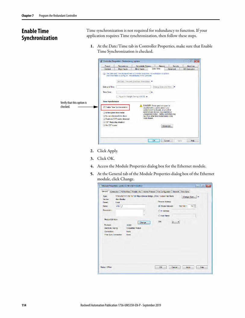
Chapter 7 Program the Redundant Controller
Enable Time Synchronization
Time synchronization is not required for redundancy to function. If your application requires Time synchronization, then follow these steps.
1. At the Date/Time tab in Controller Properties, make sure that Enable Time Synchronization is checked.
2. Click Apply.
3. Click OK.
4. Access the Module Properties dialog box for the Ethernet module.
5. At the General tab of the Module Properties dialog box of the Ethernet module, click Change.
Verify that this option is checked.
114 Rockwell Automation Publication 1756-UM535H-EN-P - September 2019

Program the Redundant Controller Chapter 7
6. In the Module Definition dialog box from the Time Sync connection pull-down menu, select Time Sync and Motion.
7. Click OK to close the dialog box.
8. At the warning dialog box, click Yes.
9. Click Apply.
10. Click OK to close the Module Properties dialog box.
Rockwell Automation Publication 1756-UM535H-EN-P - September 2019 115

Chapter 7 Program the Redundant Controller
Crossloads, Synchronization, and Switchovers
Crossloading and synchronization points are points where the primary controller transfers data to the secondary controller. Crossload and synchronization points keep the secondary controller ready to assume control in the event of a fault on the primary.
Before you begin programming your redundant controller, be aware of the impact of crossloads and synchronization on the execution of a program after a switchover. If you understand these concepts, it helps you to create programming that best meets the needs for your redundant application.
Continue reading the sections that follow for explanations of crossloads and synchronization and their relationship to switchovers and program execution.
Changing Crossload and Synchronization Settings
In the redundancy system, crossload and synchronization points for programs within the Studio 5000 Logix Designer® project are configurable. You can limit which programs data crossloading and synchronization follow. In many applications, changes to this setting can reduce the overall impact to the task scan time by reducing the number of times data is crossloaded.
If you reduce the number of crossload and synchronization points, the switchover time becomes longer. This increase in switchover time is because more programs can be rescanned after the switchover.
Synchronization is performed at the end of the last program in the program list of the task, regardless of the Synchronize Data after Execution setting for the program.
To change the synchronization setting of a program, open the Program Properties dialog box of the program and check or uncheck Synchronize Data after Execution.
Use this setting to change crossload and synchronization points.
116 Rockwell Automation Publication 1756-UM535H-EN-P - September 2019

Program the Redundant Controller Chapter 7
Default Crossload and Synchronization Settings
The default setting for a program in a redundant project is for a crossload to occur at the end of each program execution. However, for an equipment phase, the default is that the crossload not execute at the end of the phase.
Before you change the default crossload and synchronization settings, read the sections that follow so you have a complete understanding of the implications. For information about how to change the point in a task where a crossload occurs, see Changing Crossload and Synchronization Settings on page 116.
Recommended Task Types
To avoid anomalies after a switchover occurs, we recommend that you use only one of these task configurations when programming your redundant controllers. Use either of the following:
• One continuous task• Multiple periodic tasks, each with unique priorities and periods
Only the single highest-priority periodic task can ensure bumpless output switching on switchover. The sections that follow explain the impact of crossloads and synchronization after a switchover based on the task structure you use.
Continuous Task After Switchover
After a switchover occurs within a controller project that contains only a continuous task, the new primary begins executing at the last crossload and synchronization point. Depending on your crossload and synchronization setting, the program that the new primary controller begins with can be the following:
• The program that the switchover interrupted• The program that immediately follows the last crossload and
synchronization point
Rockwell Automation Publication 1756-UM535H-EN-P - September 2019 117
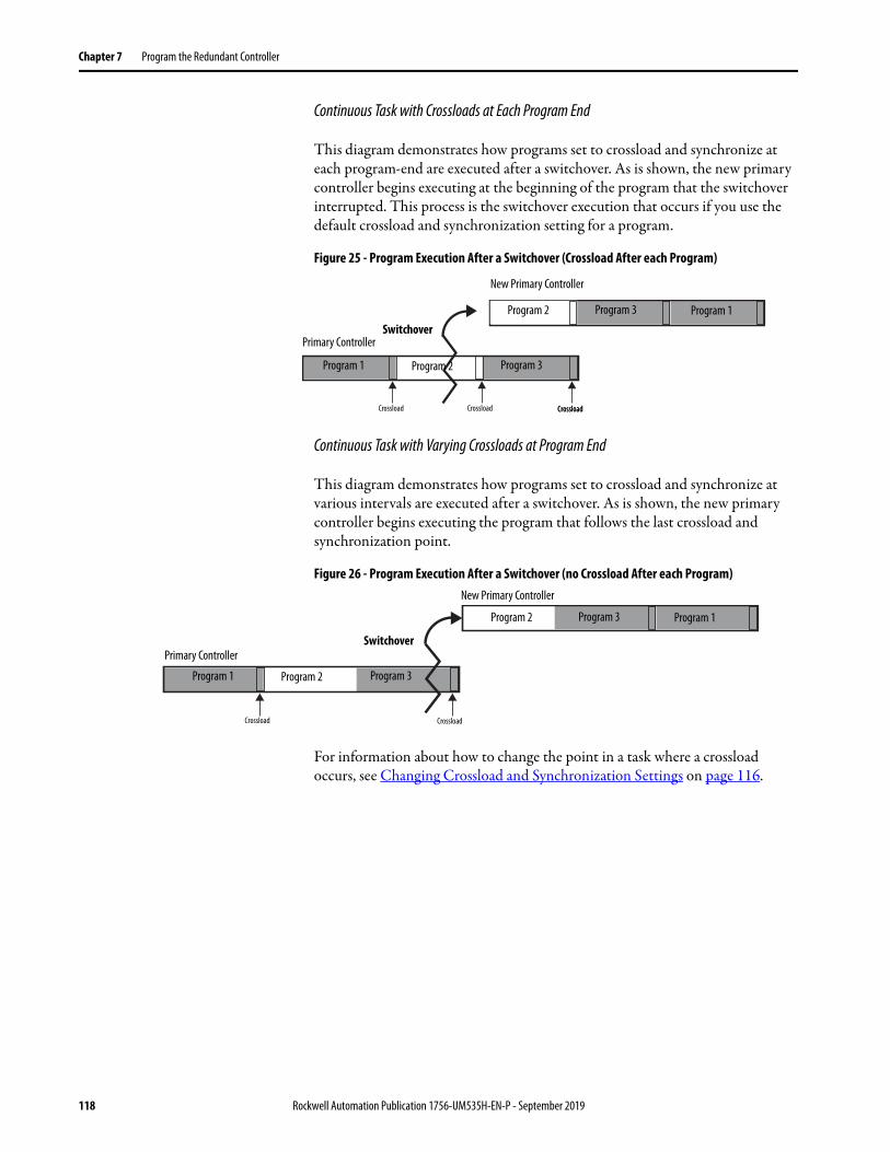
Chapter 7 Program the Redundant Controller
Continuous Task with Crossloads at Each Program End
This diagram demonstrates how programs set to crossload and synchronize at each program-end are executed after a switchover. As is shown, the new primary controller begins executing at the beginning of the program that the switchover interrupted. This process is the switchover execution that occurs if you use the default crossload and synchronization setting for a program.
Figure 25 - Program Execution After a Switchover (Crossload After each Program)
Continuous Task with Varying Crossloads at Program End
This diagram demonstrates how programs set to crossload and synchronize at various intervals are executed after a switchover. As is shown, the new primary controller begins executing the program that follows the last crossload and synchronization point.
Figure 26 - Program Execution After a Switchover (no Crossload After each Program)
For information about how to change the point in a task where a crossload occurs, see Changing Crossload and Synchronization Settings on page 116.
Primary Controller
New Primary Controller
Program 2 Program 3 Program 1
Program 1 Program 2 Program 3
Switchover
CrossloadCrossload CrossloadCrossload
Primary Controller
New Primary Controller
Program 2 Program 3 Program 1
Program 1 Program 2 Program 3
Switchover
CrossloadCrossload
118 Rockwell Automation Publication 1756-UM535H-EN-P - September 2019

Program the Redundant Controller Chapter 7
Multiple Periodic Tasks
In a project where multiple periodic tasks are used, the point where program execution begins after a switchover depends on the following:
• Crossload and synchronization settings• Task priority settings
As with the continuous task, the controller begins executing at the program that follows the last crossload and synchronization point.
In addition, a higher priority task can interrupt a lower priority task. If a switchover occurs during or just after the higher priority task executes and the lower priority task has not been completed, then the lower priority task and programs are executed from the point at which the last crossload occurred.
This diagram demonstrates how tasks at different priorities execute if a switchover occurs while a lower priority task is executing. The crossload and synchronization points in this example are set to occur only at the end of the last program within the tasks. The points are not set to occur at the end of each program.
Figure 27 - Normal Periodic Task Execution (no switchover)
ATTENTION: If you use multiple periodic tasks, program all crucial outputs within the highest-priority task. Failure to program outputs in the highest-priority task can result in outputs changing state if a switchover occurs.
Crossload
Crossload
Task - Priority 2
Task - Priority 1
Task - Priority 2
Task - Priority 1
Higher-priority Task Interrupts
Lower-priority Task Resumes
Program 3
Program 3Program 2Program 1 Program 3Program 2Program 1
Program 1 Progra am 2
Crossload
Rockwell Automation Publication 1756-UM535H-EN-P - September 2019 119

Chapter 7 Program the Redundant Controller
The following diagram shows a lower priority task that has not been completed and a switchover occurs. The lower priority task and programs are executed from the beginning of the program where the switchover occurred. This result is because the program uses the default configuration and crossloads and synchronization points occur at the end of each program.
Figure 28 - Periodic Task Execution After Switchover When Configured to Crossload After Programs
The following diagram shows a lower priority task that has not been completed and a switchover occurs. The lower priority task and programs are executed from the beginning and not at the program where the switchover occurred. This result is because the crossloads and synchronization points were not configured to occur at the end of each program.
Figure 29 - Periodic Task Execution After Switchover When Configured Not to Crossload After Programs
For more information about programs and tasks with controllers, see the Logix 5000 Controllers Tasks, Programs, and Routines Programming Manual, publication 1756-PM005.
Prim
ary
New
Prim
ary
Task - Priority 1Program 2
Task - Priority 2
Task - Priority 2
Task - Priority 1
Task - Priority 2
Program 3
Program 3Program 1 Program m 2
Program 2 Program 3
Program 2 Program 3Program 1
Crossload
Crossload
SwitchoverCrossload
Higher-priority Task Interrupts
Lower-priority Task Resumes
CrossloadCrossload
Task - Priority 2
Task - Priority 2
Switchover
Prim
ary
New
Prim
ary
Program 2 Program 3
Program 3Program 1 Progra am 2
Program 2 Program 3
Program 2 Program 3Program 1
CrossloadHigher-priority Task Interrupts
Lower-priority Task Resumes
Task - Priority 2
Switchover
Task - Priority 2
Task - Priority 2
Program 1
Program 1Crossload
120 Rockwell Automation Publication 1756-UM535H-EN-P - September 2019

Program the Redundant Controller Chapter 7
Crossloads and Scan Time It is important to plan for controller crossloads because the length of the crossloads affects the scan time of your program. A crossload is a transfer of data from the primary controller to the secondary controller. The crossload can occur at the end of each program or at the end of the last program in a task.
The scan time of your program or phase is a total of the program execution time and the crossload time. The following diagram demonstrates this concept.
Figure 30 - Crossload and Scan Time
Estimate the Crossload Time
The amount of time that is required for a crossload is primarily dependent upon the amount of data being crossloaded. During a crossload, any tag that has been written to during the program execution is crossloaded. Even if a tag has not changed, but has been rewritten during the program execution, it is crossloaded.
The crossload requires time to transfer tag value changes. The crossload also requires a small amount of overhead time to communicate information about the program being executed
Redundancy Object Attributes for Crossload Times
Before you complete calculations to estimate the crossload time, you must use a Get System Value (GSV) instruction to read certain attributes of the redundancy object. These attributes are data transfer sizes that are measured in DINTs (4-byte words) and are used to calculate the estimated crossload time.
This table indicates the two attributes that you can choose to get specific to the crossload data transfer size. Get the attribute value that meets your application requirements.
TIP To get these attributes, you do not need to have the secondary chassis installed or operating. If you do not have the secondary chassis operating, the attribute values read indicate what data sizes would be transferred if the secondary chassis was in use.
Program Scan Time
Execution of Program Crossload
Rockwell Automation Publication 1756-UM535H-EN-P - September 2019 121

Chapter 7 Program the Redundant Controller
Remember that the LastDataTransferSize attribute refers to the transfer size of the previous crossload and synchronization point, which occurred before the program that contains the GSV instruction.
If you must measure the crossloaded data from the last program in the program list of the task, add an additional program at the end of the task that acquires the LastDataTransferSize value from the program that was formerly at the end of the task.
Equation for Estimating Crossload Times
Use this equation to estimate the crossload time of your controllers for each program after you have either of the following:
• The size of the last data transfer• The maximum size of data that is transferred
ControlLogix 5560 Controllers
Crossload time per sync point (ms) = (DINTs ∗ 0.00091) + 0.6 ms
ControlLogix 5570 Controllers
The following equations apply when a ControlLogix 5570 controller is paired with a redundancy module in both chassis in a redundancy system.
If you need the Then get this attribute value
Data size of the last data that is transferred during the last crossload
LastDataTransferSize
Data size of the largest crossload of data MaxDataTransferSize
Table 12 - Crossload Times for ControlLogix 5570 Controllers
Controller Paired with Redundancy Module Crossload Time
ControlLogix 5570 1756-RM2 Crossload time per sync point (ms) = (DINTs * 0.000275) + 0.54 ms
1756-RM/B Crossload time per sync point (ms) = (DINTs ∗0.00043) + 0.3 ms
1756-RM/A Crossload time per sync point (ms) = (DINTs ∗ 0.00091) + 0.6 msWhere DINTs is the size of the data transferred measured in 4-byte words.
TIP A sync point is a mechanism that the primary controller uses to keep the secondary controller in sync. By default, at the end of each program scan, the primary controller sends the secondary controller the sync point and the secondary controller responds by moving its execution pointer to match the primary controller.The default for phases is not to send a sync point.In revision 16.05x and later, the option exists to manipulate the sync points for faster program execution.
122 Rockwell Automation Publication 1756-UM535H-EN-P - September 2019

Program the Redundant Controller Chapter 7
Program to Minimize Scan Times
There are several aspects of your program that must be as efficient as possible to facilitate the fastest possible switchover because total program scan time impacts system switchover time. The sections that follow describe methods to make your program more efficient to minimize your program scan time.
These methods make your program more efficient and minimize program scan times:
• Use a ControlLogix 5570 Controller with a 1756-RM2 Redundancy Module
• Use Multiple Controllers• Minimize the Number of Programs• Manage Tags for Efficient Crossloads• Use Concise Programming
Use a ControlLogix 5570 Controller with a 1756-RM2 Redundancy Module
In redundancy system revision 19.053 and later, you can use ControlLogix 5570 controllers in your application. Relative to the redundancy module being used, the ControlLogix 5570 controllers scan the controller program faster than ControlLogix 5560 controllers. The ControlLogix 5570 controllers also scan the controller program fastest if the redundancy system uses the 1756-RM2/A redundancy module.
If your application needs better controller performance, we recommend that you update from ControlLogix 5560 controllers to ControlLogix 5570 controllers and use 1756-RM2 redundancy modules.
Use Multiple Controllers
When possible, use multiple controllers in your redundant system. If you use multiple controllers, you can strategically program between the controllers so the program execution and scan times are faster.
IMPORTANT Only the 1756-L72, 1756-L73, 1756-L74, and 1756-L75 controllers can be used with the 1756-RM2 redundancy modules and revision 19.053.
Rockwell Automation Publication 1756-UM535H-EN-P - September 2019 123

Chapter 7 Program the Redundant Controller
Minimize the Number of Programs
When programming a redundant controller, use the fewest programs possible. Use of the fewest programs possible is especially important if you plan to crossload data and synchronize the controllers after the execution of each program.
If you must crossload data at the end of each program, make these programming considerations to minimize the crossload impact on the program scan time:
• Use only one or a few programs.
• Divide each program into the number of routines that is appropriate for your application. A routine does not cause a crossload or increase the scan time.
• Use the main routine of each program to call the other routines of the program.
• If you want to use multiple tasks for different scan periods, use only one program in each task.
Manage Tags for Efficient Crossloads
Manage your data tags as the following sections recommend to program for more efficient crossloads of data and reduce the amount of time that is required for a crossload to execute.
Figure 31 - Use of Multiple Routines (preferred) Figure 31 - Use of Multiple Programs (not preferred)
124 Rockwell Automation Publication 1756-UM535H-EN-P - September 2019
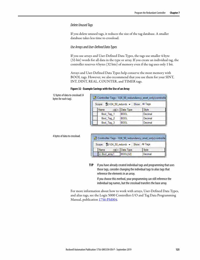
Program the Redundant Controller Chapter 7
Delete Unused Tags
If you delete unused tags, it reduces the size of the tag database. A smaller database takes less time to crossload.
Use Arrays and User-Defined Data Types
If you use arrays and User-Defined Data Types, the tags use smaller 4-byte (32-bit) words for all data in the type or array. If you create an individual tag, the controller reserves 4 bytes (32 bits) of memory even if the tag uses only 1 bit.
Arrays and User-Defined Data Types help conserve the most memory with BOOL tags. However, we also recommend that you use them for your SINT, INT, DINT, REAL, COUNTER, and TIMER tags.
Figure 32 - Example Savings with the Use of an Array
For more information about how to work with arrays, User-Defined Data Types, and alias tags, see the Logix 5000 Controllers I/O and Tag Data Programming Manual, publication 1756-PM004.
4 bytes of data to crossload.
12 bytes of data to crossload (4 bytes for each tag).
TIP If you have already created individual tags and programming that uses those tags, consider changing the individual tags to alias tags that reference the elements in an array.If you choose this method, your programming can still reference the individual tag names, but the crossload transfers the base array.
Rockwell Automation Publication 1756-UM535H-EN-P - September 2019 125

Chapter 7 Program the Redundant Controller
Group Data Types Together in User-Defined Data Types
When you create a User-Defined Data Type for use in your redundancy program, group like data types together. Grouping like data types compresses the data size and helps reduce the amount of data that is transferred during a crossload.
Figure 33 - Example of Bytes Saved by Grouping Like Data
Group Data into Arrays of User-Defined Data Types by Frequency of Use
To update the secondary controller, the primary controller divides its memory into blocks of 256 bytes. Anytime an instruction writes a value, the primary controller crossloads the entire block that contains the value. For example, if your logic writes only 1 BOOL value to a block, the controller crossloads the entire block (256 bytes).
To minimize crossload time, group your data by how frequently your program uses it.
Data Types Grouped
Data Types Ungrouped
126 Rockwell Automation Publication 1756-UM535H-EN-P - September 2019
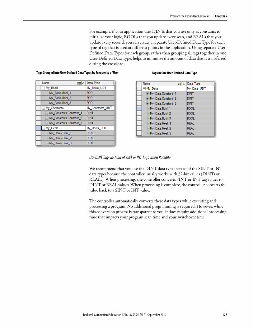
Program the Redundant Controller Chapter 7
For example, if your application uses DINTs that you use only as constants to initialize your logic, BOOLs that you update every scan, and REALs that you update every second, you can create a separate User-Defined Data Type for each type of tag that is used at different points in the application. Using separate User-Defined Data Types for each group, rather than grouping all tags together in one User-Defined Data Type, helps to minimize the amount of data that is transferred during the crossload.
Use DINT Tags Instead of SINT or INT Tags when Possible
We recommend that you use the DINT data type instead of the SINT or INT data types because the controller usually works with 32-bit values (DINTs or REALs). When processing, the controller converts SINT or INT tag values to DINT or REAL values. When processing is complete, the controller converts the value back to a SINT or INT value.
The controller automatically converts these data types while executing and processing a program. No additional programming is required. However, while this conversion process is transparent to you, it does require additional processing time that impacts your program scan time and your switchover time.
Tags Grouped into User-Defined Data Types by Frequency of Use Tags in One User-Defined Data Type
Rockwell Automation Publication 1756-UM535H-EN-P - September 2019 127
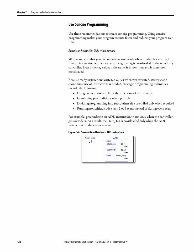
Chapter 7 Program the Redundant Controller
Use Concise Programming
Use these recommendations to create concise programming. Using concise programming makes your program execute faster and reduces your program scan time.
Execute an Instruction Only when Needed
We recommend that you execute instructions only when needed because each time an instruction writes a value to a tag, the tag is crossloaded to the secondary controller. Even if the tag values is the same, it is rewritten and is therefore crossloaded.
Because many instructions write tag values whenever executed, strategic and economical use of instructions is needed. Strategic programming techniques include the following:
• Using preconditions to limit the execution of instructions• Combining preconditions when possible• Dividing programming into subroutines that are called only when required• Running noncritical code every 2 or 3 scans instead of during every scan
For example, precondition an ADD instruction to run only when the controller gets new data. As a result, the Dest_Tag is crossloaded only when the ADD instruction produces a new value.
Figure 34 - Precondition Used with ADD Instruction
128 Rockwell Automation Publication 1756-UM535H-EN-P - September 2019
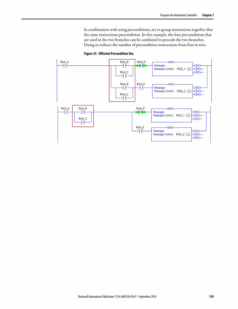
Program the Redundant Controller Chapter 7
In combination with using preconditions, try to group instructions together that the same instructions precondition. In this example, the four preconditions that are used in the two branches can be combined to precede the two branches. Doing so reduces the number of precondition instructions from four to two.
Figure 35 - Efficient Precondition Use
Rockwell Automation Publication 1756-UM535H-EN-P - September 2019 129

Chapter 7 Program the Redundant Controller
Program to Maintain Data Integrity
When programming your redundant controllers, there are some instructions and techniques that can cause data loss or corruption when used. These instructions and techniques include the following:
• Array (File)/Shift Instructions• Scan-dependent Logic
Array (File)/Shift Instructions
Interruptions to Array (File)/Shift Instructions by a higher priority task and then switchover can result in an incomplete data shift and corrupted data.
The following Array (File)/Shift instructions can result in corrupt data in the event of a switchover:
• Bit Shift Left (BSL)• Bit Shift Right (BSR)• FIFO Unload (FFU)
If Array (File)/Shift Instructions are used, these system behaviors can result:
1. If a higher priority task interrupts one of the Array (File)/Shift instructions, the partially shifted array values are crossloaded to the secondary controller.
2. If a switchover occurs before the instruction completes its execution, data remains only partially shifted.
3. After a switchover, the secondary controller starts its executing at the beginning of the program. When it reaches the partially executed instruction, it shifts the data again.
130 Rockwell Automation Publication 1756-UM535H-EN-P - September 2019

Program the Redundant Controller Chapter 7
Buffering Critical Data
If you cannot place Array (File)/Shift instructions in the highest-priority task, consider using a buffer with Copy File (COP) and Synchronous Copy File (CPS) instructions to maintain the integrity of the array of data.
The programming example that is shown here shows the use of a COP instruction to move data into a buffer array. The BSL instruction uses the data in that buffer array. The CPS instruction updates the array tag and maintains data integrity because a higher priority task cannot interrupt it. If a switchover occurs, the source data (that is, the array tag) remains unaffected.
Figure 36 - Using a Buffer to Maintain Data During Shift
For more information about BSL, BSR, FFU, COP, and CPS instructions see the Logix 5000 Controllers General Instructions Reference Manual, publication 1756-RM003.
Scan-dependent Logic
If you program a lower priority task so that one instruction is dependent on another instruction that occurs elsewhere in your program, a task interrupt and switchover can disrupt your programming. The disruption can occur because the higher priority task can interrupt the lower priority task and then a switchover can occur before the lower priority task is completed.
When the lower priority task is executed from the beginning by the new primary controller after the switchover, the dependent instruction can fail to execute at the most recent value or state.
Rockwell Automation Publication 1756-UM535H-EN-P - September 2019 131

Chapter 7 Program the Redundant Controller
For example, if a higher priority task interrupts the logic that is shown in this example, the value of scan_count.ACC is sent to the secondary controller at the end of the program in the higher priority task. If a switchover occurs before the primary controller completes the EQU instruction, the new primary controller starts its execution at the beginning of the program and the EQU instruction misses the last value of scan_count.ACC. As a result, any programming that uses the Scan_Count_Light tag can also execute by using incorrect data.
Table 13 - Scan-dependent Logic
Interrupt by higher priority task.
Switchover
Use a Counter instruction to count each scan of the program.
An Equal To instruction uses the accumulated scan_count value as a reference to turn on an indicator when the thousandth scan is complete.
132 Rockwell Automation Publication 1756-UM535H-EN-P - September 2019

Program the Redundant Controller Chapter 7
Bind Dependent Instructions with UID and UIE Instructions
If you cannot place scan-dependent instructions in the highest priority task, consider using the User Interrupt Disable (UID) and User Interrupt Enable (UIE) to prevent a higher priority task from interrupting the scan-dependent logic.
For example, if you bind the scan-dependent logic that is previously shown, a higher priority task would not interrupt the dependent instructions and a switchover would not result in inconsistent data.
Figure 37 - Scan-dependent Instructions Bound with UID and UIE Instructions
For more information about UID and UIE instructions, see the Logix 5000 Controllers General Instructions Reference Manual, publication 1756-RM003.
UID and UIE keep higher priority tasks from interrupting the logic.
Use a Counter instruction to count each scan of the program.
An Equal To instruction uses the accumulated scan_count value as a reference to turn on an indicator when the thousandth scan is complete.
Rockwell Automation Publication 1756-UM535H-EN-P - September 2019 133
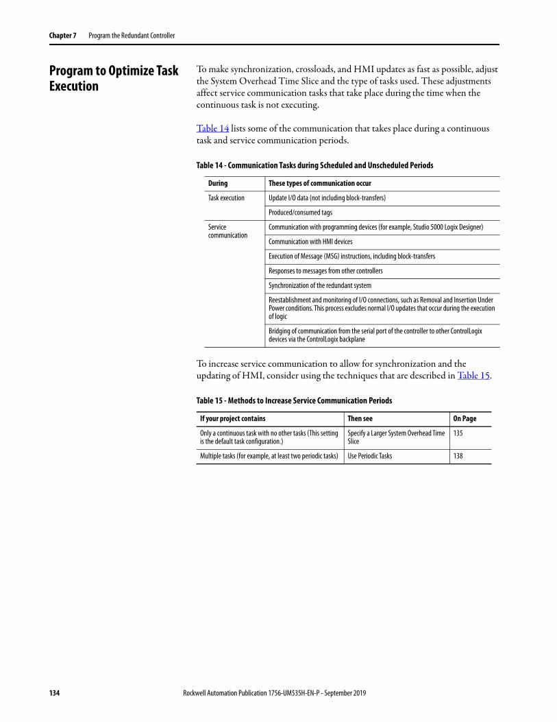
Chapter 7 Program the Redundant Controller
Program to Optimize Task Execution
To make synchronization, crossloads, and HMI updates as fast as possible, adjust the System Overhead Time Slice and the type of tasks used. These adjustments affect service communication tasks that take place during the time when the continuous task is not executing.
Table 14 lists some of the communication that takes place during a continuous task and service communication periods.
To increase service communication to allow for synchronization and the updating of HMI, consider using the techniques that are described in Table 15.
Table 14 - Communication Tasks during Scheduled and Unscheduled Periods
During These types of communication occur
Task execution Update I/O data (not including block-transfers)
Produced/consumed tags
Service communication
Communication with programming devices (for example, Studio 5000 Logix Designer)
Communication with HMI devices
Execution of Message (MSG) instructions, including block-transfers
Responses to messages from other controllers
Synchronization of the redundant system
Reestablishment and monitoring of I/O connections, such as Removal and Insertion Under Power conditions. This process excludes normal I/O updates that occur during the execution of logic
Bridging of communication from the serial port of the controller to other ControlLogix devices via the ControlLogix backplane
Table 15 - Methods to Increase Service Communication Periods
If your project contains Then see On Page
Only a continuous task with no other tasks (This setting is the default task configuration.)
Specify a Larger System Overhead Time Slice
135
Multiple tasks (for example, at least two periodic tasks) Use Periodic Tasks 138
134 Rockwell Automation Publication 1756-UM535H-EN-P - September 2019

Program the Redundant Controller Chapter 7
Specify a Larger System Overhead Time Slice
The system overhead time slice specifies the percentage of time the controller devotes to servicing communication, excluding the time for periodic tasks. The controller interrupts the continuous task to service communication, and then resumes the continuous task.
Table 16 shows the ratio between executing the continuous task and servicing communication at various overhead time slices. Consider the following:
• When the system overhead time slice setting is between 10% and up to 50%, the time that is allocated for servicing communication is fixed at 1 ms. The continuous task time slice changes to produce the desired ratio.
• When the system overhead time slice is greater than 50…90%, the time that is allocated to the continuous task is fixed at 1 ms. The time that is allocated to servicing communication changes to produce the desired ratio.
Table 16 - Overhead Time Slice
At this time slice The continuous tasks runs for And service communication occurs for as long as
10% 9 ms 1 ms
20% 4 ms 1 ms
25% 3 ms 1 ms
33% 2 ms 1 ms
50% 1 ms 1 ms
66% 1 ms 2 ms
75% 1 ms 3 ms
80% 1 ms 4 ms
90% 1 ms 9 ms
Rockwell Automation Publication 1756-UM535H-EN-P - September 2019 135

Chapter 7 Program the Redundant Controller
System Overhead Time Slice Examples
This diagram illustrates a system where the System Overhead Time Slice is set to 20% (default). With this percentage, communication is serviced after every 4 ms of continuous task execution. Communication is serviced for up to 1 ms before the continuous task is restarted.
Figure 38 - System Overhead Time Slice Set to 20%
This diagram illustrates a system where the System Overhead Time Slice is set to 33%. With this percentage, communication is serviced after every 2 ms of continuous task execution. Communication is serviced for up to 1 ms before the continuous task is restarted.
Figure 39 - System Overhead Time Slice Set to 33%
Change the System Overhead Time Slice
To change the System Overhead Time Slice, access the Controller Properties dialog box and click the Advanced tab. You can enter your System Overhead Time Slice value.
Legend:
Task executes.
Task is interrupted (suspended).
1 ms 1 ms 1 ms 1 ms 1 ms
Service Communication
4 ms 4 ms 4 ms 4 ms 4 ms
Continuous Task
1 ms 1 ms 1 ms 1 ms 1 ms 1 ms 1 ms 1 ms
Service Communication
2 ms 2 ms 2 ms 2 ms 2 ms 2 ms 2 ms 2 ms 2 ms
Continuous Task
136 Rockwell Automation Publication 1756-UM535H-EN-P - September 2019

Program the Redundant Controller Chapter 7
Options for During the Unused System Overhead Time Slice
Enable the Run Continuous Task option (default setting) if you want the controller to revert to running the continuous task as soon as the communication servicing task has no pending activity. This setting results in only using the allocated communication servicing time if there is a need for it.
When the Run Continuous Task option selected, the controller immediately returns to the continuous task.
Use the Reserve for System Task option to allocate the entire 1 ms of the System Overhead Time Slice for service communication - even if no service communication or background tasks must be executed. You can choose to use this option without service communication or background tasks to simulate a communication load on the controller during design and programming. Use this setting for testing only.
IMPORTANT We do not recommend that you use the Reserve for System Task option for production. The option was developed to simulate systems with high communication requirements.
Rockwell Automation Publication 1756-UM535H-EN-P - September 2019 137
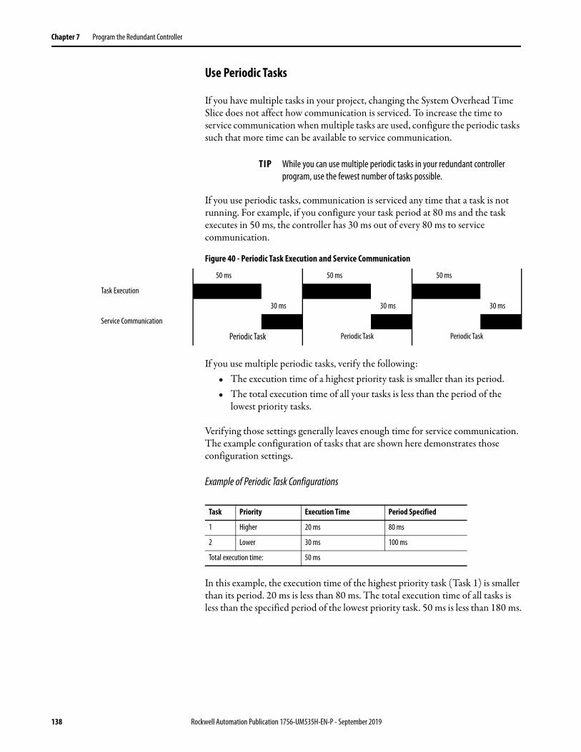
Chapter 7 Program the Redundant Controller
Use Periodic Tasks
If you have multiple tasks in your project, changing the System Overhead Time Slice does not affect how communication is serviced. To increase the time to service communication when multiple tasks are used, configure the periodic tasks such that more time can be available to service communication.
If you use periodic tasks, communication is serviced any time that a task is not running. For example, if you configure your task period at 80 ms and the task executes in 50 ms, the controller has 30 ms out of every 80 ms to service communication.
Figure 40 - Periodic Task Execution and Service Communication
If you use multiple periodic tasks, verify the following:• The execution time of a highest priority task is smaller than its period.• The total execution time of all your tasks is less than the period of the
lowest priority tasks.
Verifying those settings generally leaves enough time for service communication. The example configuration of tasks that are shown here demonstrates those configuration settings.
Example of Periodic Task Configurations
In this example, the execution time of the highest priority task (Task 1) is smaller than its period. 20 ms is less than 80 ms. The total execution time of all tasks is less than the specified period of the lowest priority task. 50 ms is less than 180 ms.
TIP While you can use multiple periodic tasks in your redundant controller program, use the fewest number of tasks possible.
50 ms 50 ms 50 ms
Task Execution
30 ms 30 ms 30 ms
Service Communication
Periodic Task Periodic Task Periodic Task
Task Priority Execution Time Period Specified
1 Higher 20 ms 80 ms
2 Lower 30 ms 100 ms
Total execution time: 50 ms
138 Rockwell Automation Publication 1756-UM535H-EN-P - September 2019
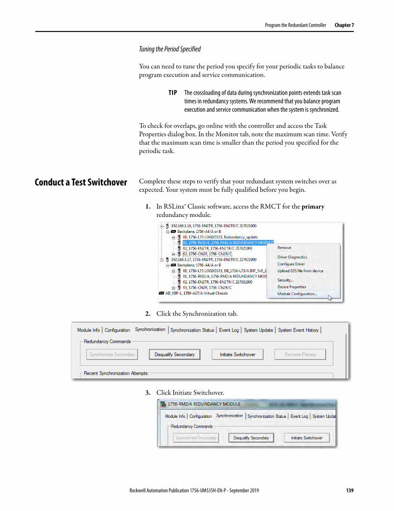
Program the Redundant Controller Chapter 7
Tuning the Period Specified
You can need to tune the period you specify for your periodic tasks to balance program execution and service communication.
To check for overlaps, go online with the controller and access the Task Properties dialog box. In the Monitor tab, note the maximum scan time. Verify that the maximum scan time is smaller than the period you specified for the periodic task.
Conduct a Test Switchover Complete these steps to verify that your redundant system switches over as expected. Your system must be fully qualified before you begin.
1. In RSLinx® Classic software, access the RMCT for the primary redundancy module.
2. Click the Synchronization tab.
3. Click Initiate Switchover.
TIP The crossloading of data during synchronization points extends task scan times in redundancy systems. We recommend that you balance program execution and service communication when the system is synchronized.
Rockwell Automation Publication 1756-UM535H-EN-P - September 2019 139
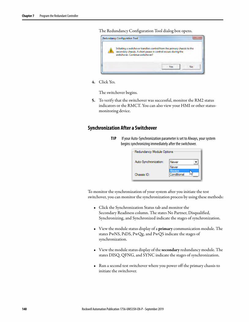
Chapter 7 Program the Redundant Controller
The Redundancy Configuration Tool dialog box opens.
4. Click Yes.
The switchover begins.
5. To verify that the switchover was successful, monitor the RM2 status indicators or the RMCT. You can also view your HMI or other status-monitoring device.
Synchronization After a Switchover
To monitor the synchronization of your system after you initiate the test switchover, you can monitor the synchronization process by using these methods:
• Click the Synchronization Status tab and monitor the Secondary Readiness column. The states No Partner, Disqualified, Synchronizing, and Synchronized indicate the stages of synchronization.
• View the module status display of a primary communication module. The states PwNS, PsDS, PwQg, and PwQS indicate the stages of synchronization.
• View the module status display of the secondary redundancy module. The states DISQ, QFNG, and SYNC indicate the stages of synchronization.
• Run a second test switchover where you power off the primary chassis to initiate the switchover.
TIP If your Auto-Synchronization parameter is set to Always, your system begins synchronizing immediately after the switchover.
140 Rockwell Automation Publication 1756-UM535H-EN-P - September 2019

Program the Redundant Controller Chapter 7
Program Logic to Run After a Switchover
If your application requires certain logic or instructions to be executed after a switchover, then use programming and tags similar to the values shown in this example.
Figure 41 - Precondition Used to Run Logic After Switchover - Ladder Logic
This GSV instruction obtains the chassis ID of the primary chassis (that is, the chassis that is in control).
If this is the first program scan, then use the current primary chassis ID as the chassis ID for the last scan.
If a switchover occurs, the chassis ID changes. The NEQ instruction compares the current and last primary chassis ID values. If the values are different, the Switchover_Occurred bit is turned on. In addition, the current primary chassis ID is moved into the last
chassis ID.
If the Switchover_Occurred bit is on, then the instructions added to this rung are executed and the Switchover_Occurred bit is reset.
Add your switchover-dependent instructions here.
Rockwell Automation Publication 1756-UM535H-EN-P - September 2019 141

Chapter 7 Program the Redundant Controller
Use Messages for Redundancy Commands
For some applications, consider programming the controller to issue redundancy system commands via the redundancy modules. The sections that follow explain how to configure a MSG instruction to issue a redundancy command.
Verify User Program Control
For a MSG instruction to issue a command via the redundancy modules, the redundancy modules must be configured for user program control.
To verify that the modules are enabled for user program control, access the Configuration tab of the RMCT and verify that Enable User Program Control is checked.
Figure 42 - Enable User Program Control in the RMCT
Use an Unconnected Message
When you add your MSG instruction for issuing the command through the redundancy modules, configure it as an unconnected message.
142 Rockwell Automation Publication 1756-UM535H-EN-P - September 2019

Program the Redundant Controller Chapter 7
Configure the MSG Instruction
Use the MSG configuration settings that correspond to the command you intend to issue to the redundancy modules.
Initiate a Switchover
To initiate a switchover, use the MSG instruction parameters that are listed in Table 17.
If you must See page
Initiate a Switchover 143
Disqualify the Secondary Chassis 145
Synchronize the Secondary Chassis 145
Set the Redundancy Module Date and Time 146
Table 17 - MSG Instruction to Initiate a Switchover
In this tab Edit this element To use this value
Configuration Message Type CIP™ Generic
Service Type Custom
Service Code 4e
Class bf
Instance 1
Attribute None - no value needed
Source Element INT tag with a value of 1
Source Length 2
Destination Element None - no value needed.
Communication Path 1 - the slot number of the 1756-RM, 1756-RM2, 1756-RMXT, or 1756-RM2XT module.
Connected box Leave the Connected checkbox unchecked.
Rockwell Automation Publication 1756-UM535H-EN-P - September 2019 143

Chapter 7 Program the Redundant Controller
Use Table 18 to when using MSG instructions during a switchover.
Table 18 - MSG Instruction Behavior During a Switchover
If the MSG instruction is Then
From a redundant controller In a redundant controller, any MSG instruction that is in progress during a switchover experiences an error.(The ER bit of the instruction turns on.) After the switchover, normal communication resumes.
To a redundant controller For any MSG instruction from a controller in another chassis to a redundant controller, cache the connection:Properties of the Message to the Redundant Controller
Configured Message Instructions
If the MSG instructionoriginates from aredundant controller
Then
During a switchover The message instructions status bits are updated asynchronously to the program scan. Consequently, you cannot crossload your message instructions status bits to a secondary controller.During a switchover, any active message instructions become inactive. When this change occurs, you must reinitialize the execution of your message instructions in the new primary controller.
During qualification The scrolling display changes from CMPT for compatible to Qfng for qualifying.• If a configured message is cached, the primary controller automatically establishes a connection with no errors.• If a configured message is uncached or unconnected, the primary controller receives Error 1 Extended Error 301, No Buffer
Memory.
If the message is targeted to a redundant controller
Then
During the erroring out of a message All backplane communication ceases. This stoppage lets the redundant controller receive the message instruction that is required to perform a switchover or any diagnostics.Important: If any of your messages are active during a switchover, you can expect one of these things to happen:
• Cached and connected messages cause the message instruction to pause for 7.5 seconds because the initiating controller has not received a response from the targeted controller. For cached messages, the message instruction tries to execute three more times, each attempt followed by a pause of 7.5 seconds. If, after 30 seconds pass, the targeted controller does not respond to the initiating controller, then the switchover errors out with connected time-out Error 1 Extended Error 203.
An example of a connected message would be CIP data table read-and-write messages after a connection has been established.
• Uncached messages error out after 30 seconds if you have initiated them because the initiating controller never received a reply to the forward-open request. The error is Error 1F Extended Error 204, an unconnected time-out.
Examples of uncached messages would include CIP generic messages and messages that are captured during theconnection process.
During qualification Cached messages that run with no errors. A connection has been established.Connected, but uncached, messages or unconnected messages error out with Error 1 Extended Error 301, NoBuffer Memory.
144 Rockwell Automation Publication 1756-UM535H-EN-P - September 2019
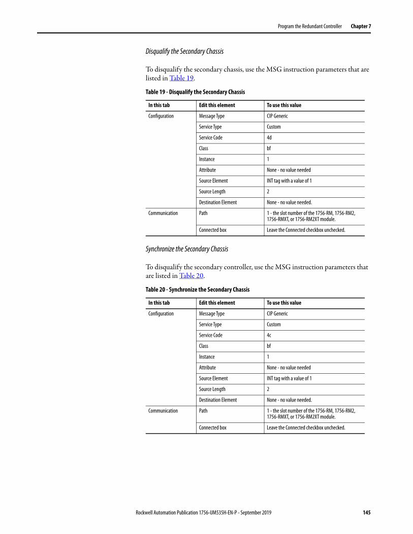
Program the Redundant Controller Chapter 7
Disqualify the Secondary Chassis
To disqualify the secondary chassis, use the MSG instruction parameters that are listed in Table 19.
Synchronize the Secondary Chassis
To disqualify the secondary controller, use the MSG instruction parameters that are listed in Table 20.
Table 19 - Disqualify the Secondary Chassis
In this tab Edit this element To use this value
Configuration Message Type CIP Generic
Service Type Custom
Service Code 4d
Class bf
Instance 1
Attribute None - no value needed
Source Element INT tag with a value of 1
Source Length 2
Destination Element None - no value needed.
Communication Path 1 - the slot number of the 1756-RM, 1756-RM2, 1756-RMXT, or 1756-RM2XT module.
Connected box Leave the Connected checkbox unchecked.
Table 20 - Synchronize the Secondary Chassis
In this tab Edit this element To use this value
Configuration Message Type CIP Generic
Service Type Custom
Service Code 4c
Class bf
Instance 1
Attribute None - no value needed
Source Element INT tag with a value of 1
Source Length 2
Destination Element None - no value needed.
Communication Path 1 - the slot number of the 1756-RM, 1756-RM2, 1756-RMXT, or 1756-RM2XT module.
Connected box Leave the Connected checkbox unchecked.
Rockwell Automation Publication 1756-UM535H-EN-P - September 2019 145

Chapter 7 Program the Redundant Controller
Set the Redundancy Module Date and Time
To set the WallClockTime of the 1756-RM module, use the MSG instruction parameters that are listed in Table 21.
Set the Task Watchdog Watchdog times set for tasks in redundancy applications must be larger than watchdog times set for tasks in non-redundancy applications because more time is required to conduct crossloads and synchronization.
An increase in the required watchdog time is also a result of the way programs are executed in the event of a switchover. A program or programs can be executed a second time after switchover. This action depends on when in the task or program the switchover occurs and where in the task crossload and synchronization occurs.
If a program is executed a second time, the length of time that is required for the program scan is increased. However, the watchdog timer is not reset and continues to countdown from the beginning of the task that the old primary controller started. Therefore, the watchdog timer must be configured to account for the potential of additional program scans.
Table 21 - Set WallClockTime
In this tab Edit this element To use this value
Configuration Message Type CIP Generic
Service Type Custom
Service Code 10
Class 8b
Instance 1
Attribute b
Source Element WallClockTime[0] WallClockTime is a DINT[2] array that stores the CurrentValue of the WallClockTime object
Source Length 8
Destination Element None - no value needed.
Communication Path 1 - the slot number of the 1756-RM, 1756-RM2, 1756-RMXT, or 1756-RM2XT module.
Connected box Leave the Connected checkbox unchecked.
146 Rockwell Automation Publication 1756-UM535H-EN-P - September 2019
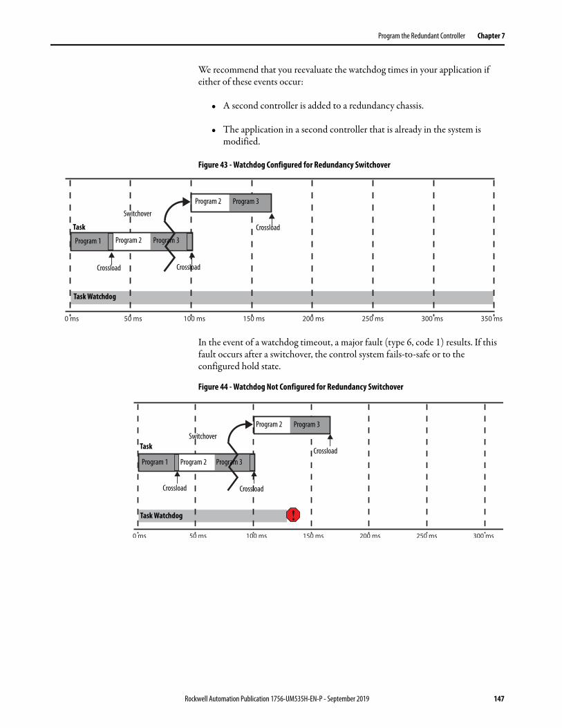
Program the Redundant Controller Chapter 7
We recommend that you reevaluate the watchdog times in your application if either of these events occur:
• A second controller is added to a redundancy chassis.
• The application in a second controller that is already in the system is modified.
Figure 43 - Watchdog Configured for Redundancy Switchover
In the event of a watchdog timeout, a major fault (type 6, code 1) results. If this fault occurs after a switchover, the control system fails-to-safe or to the configured hold state.
Figure 44 - Watchdog Not Configured for Redundancy Switchover
Crossload
CrossloadCrossload
Switchover
Program 1 Program 2 Program 3
Program 2 Program 3
Task
Task Watchdog
Crossload
CrossloadCrossload
Switchover
Program 1 Program 2 Program 3
Program 2 Program 3
Task
Task Watchdog
Rockwell Automation Publication 1756-UM535H-EN-P - September 2019 147

Chapter 7 Program the Redundant Controller
Minimum Value for the Watchdog TimeTo set Watchdog time for your ControlLogix 5560 controllers, use this table to determine which equation to use to calculate the time for each task.
The maximum_scan_time is the maximum scan time for the entire task when the secondary controller is synchronized.
To set the initial task tuning of the ControlLogix 5570 controller, follow these steps.
1. Monitor the Max Scan Time for each task while the redundant chassis pair is synchronized.
2. Set the Watchdog times for each task to three times the Max Scan Time.
3. To configure each Task Period, use the Logix 5000™ Task Monitor Tool.(1)
a. Adjust the Task periods of each so that the maximum scan time is less than 80% of the task period rate.
b. Adjust the Task periods so that the Logix CPU % utilization is never above 80%.
c. While performing these tests, the HMI and any other external systems must be connected to the Logix controller.
Download the Project Download the project only to the primary controller. When the secondary controller is synchronized, the system automatically crossloads the project to the secondary controller.
If Then use this equation
Using ControlNet® I/O ms (2 * maximum_scan_time) + 150
Using Ethernet I/O ms (2 * maximum _scan_time) + 100
IMPORTANT This process works only when there is no Continuous task that is configured in the Logix application.
(1) See the PlantPAx® Process Automation System Reference Manual, publication PROCES-RM001.
IMPORTANT Verify that there are no task overlaps.
IMPORTANT If the secondary chassis was qualified and becomes disqualified after you download the project, verify that you have enabled the controller for redundancy.
148 Rockwell Automation Publication 1756-UM535H-EN-P - September 2019
Program the Redundant Controller Chapter 7
Store a Redundancy Project to Nonvolatile Memory
Use this procedure to store an updated project and firmware to the nonvolatile memory card of the controller.
This section describes how to store a project to nonvolatile memory in either of these conditions:
• Store a Project While the Controller is in Program or Remote Program Mode
• Store a Project While a System is Running
IMPORTANT We recommend that you store the same project on the nonvolatile memory cards of both controllers. By doing so, you can be assured that if a controller, primary or secondary, loses the project from its internal memory, you can load the most recent project back onto that controller.If you store the same project on the nonvolatile memory cards of both controllers, while the process is running, you must save the project on the controllers while they are in the secondary controller state. To do so, you save the project on the secondary controller, conduct a switchover, and save the project on the new secondary controller. Even if you do not plan to use the SD card, leave the card installed in the controller to collect diagnostic information that you can provide to Rockwell Automation Technical Support.For more information, see the steps in Store a Project While the Controller is in Program or Remote Program Mode on page 150 or Store a Project While a System is Running on page 151.
Rockwell Automation Publication 1756-UM535H-EN-P - September 2019 149

Chapter 7 Program the Redundant Controller
Store a Project While the Controller is in Program or Remote Program Mode
If you want to store your controller project in nonvolatile memory while your redundant system is not running, complete these steps. Before you begin, verify that a controller communication path has been specified and that you are able to go online with the primary controller.
1. Verify that the redundant chassis are synchronized. If they are not synchronized, synchronize them.
2. To put the primary controller into Program or Remote Program mode, use programming software or the mode switch.
3. In RSLinx Classic communication software, right-click the redundancy module and choose Module Configuration to open the RMCT.
4. In the Configuration tab, set the Auto-Synchronization parameter to Conditional.
5. On the Synchronization tab, click Disqualify Secondary.
6. In the programming software, access the Controller Properties dialog box and click the Nonvolatile Memory tab.
7. Click Load/Store.
8. Click <-- Store and then click Yes.
When the store is complete, we go online with the secondary controller.
150 Rockwell Automation Publication 1756-UM535H-EN-P - September 2019

Program the Redundant Controller Chapter 7
9. Complete steps 6…8 to store the project in nonvolatile memory of the secondary controller.
10. In RSLinx Classic software, open the RMCT for one of the redundancy modules in the redundant pair.
11. In the Synchronization tab, click Synchronize Secondary.
12. In the Configuration tab, set the Auto-Synchronization option to your desired setting.
Store a Project While a System is Running
If you want to store your controller project in nonvolatile memory while your redundant system is running, complete these steps.
1. Verify that the redundant chassis are synchronized.
2. In the RMCT, access the Configuration tab and set the Auto-Configuration parameter to Never.
3. In the Synchronization tab, click Disqualify Secondary.
4. Go online with the secondary controller.
5. Open the Controller Properties dialog box and click the Nonvolatile Memory tab.
6. To store the project in nonvolatile memory, click Load/Store then <--Store.
7. In the RMCT, click the Synchronization tab.
8. Click Synchronize Secondary and wait for the system to synchronize.
9. Click Initiate Switchover.
IMPORTANT Do not go online with the primary controller until you have completed this procedure.
Rockwell Automation Publication 1756-UM535H-EN-P - September 2019 151

Chapter 7 Program the Redundant Controller
10. Go online with the new secondary controller.
11. Complete step 5and step 6 to store the project.
12. In the RMCT, click the Configuration tab and set the Auto-Configuration to your desired setting.
13. In the Synchronization tab, click Synchronize Secondary.
You have completed the steps that are required to store your project while online.
Load a Project
If you must load a project from nonvolatile memory, you must first disqualify your redundancy system. You then load the project from the nonvolatile memory card to the primary controller, and resynchronize the redundant chassis once the load is complete.
For details about loading a project from nonvolatile memory, see the Logix 5000 Controllers Nonvolatile Memory Card Programming Manual, publication 1756-PM017.
Online Edits You can edit the redundant controller program while the system is online and running. However, considerations specific to redundancy must be made with considerations described in the Logix 5000 Controllers Quick Start, publication 1756-QS001.
Support for Partial Import Online
Beginning with redundancy system revision 19.052 or later, you can use the Partial Import Online (PIO) feature available in the programming software.
Consider these points when using PIO with redundancy systems at revision 19.052 or later:
• If you select Import Logix Edits as Pending or Accept Program Edits when executing a PIO, the primary controller treats the PIO feature as a set of multiple test edits where, after the import is complete, you can switch between testing the edits or not.
• We recommend that you do not use Finalize All Edits in Program when you import edits. If you use this option, any failure due to the import causes a failure on the new primary controller after a switchover.
• If edits exist in the primary controller due to a PIO, they are treated the same as normal test edits regarding the ‘Retain Test Edits at Switchover’ selection and Redundancy System Update.
• If a PIO is in progress, the primary controller rejects any attempt to qualify.
152 Rockwell Automation Publication 1756-UM535H-EN-P - September 2019

Program the Redundant Controller Chapter 7
• If you attempt to initiate a PIO on a primary controller in the process of qualifying the system, that PIO is rejected.
Rockwell Automation Publication 1756-UM535H-EN-P - September 2019 153
Chapter 7 Program the Redundant Controller
• If a switchover occurs while the PIO is still in process, a PIO to a primary controller can fail.
When the anomaly occurs and the PIO fails, you can see any of these errors:– Failed to import file 'c\...\xxx.L5x
Object already exists
– Failed to import file 'c\...\xxx.L5xAlready in request mode/state
– CIP error: Problem with a semaphore
– Internal Object Identifier (IOI) destination unknown
After switchover is complete, reattempt the PIO and it completes successfully.
There are additional considerations necessary to performing online edits:• Plan for Test Edits• Finalize Edits with Caution• Reserve Memory for Tags and Logic
Plan for Test Edits
Before you begin editing your redundant program while your system is running, verify that the Retain Test Edits on Switchover setting meets your application requirements.
If you enable the system to retain the test edits on a switchover (that is, you check Retain Test Edits on Switchover), faults that result from the test edits can also occur on the new primary controller after a switchover.
If you do not enable the system to retain the test edits on a switchover (that is, you leave Retain Test Edits on Switchover unchecked), faults that result from the test edits are not carried over to the new primary controller in the event of a switchover.
IMPORTANT We recommend that you leave the Retain Test Edits on Switchover setting at the default (that is, unchecked) to avoid faulting both controllers when testing your edits.
154 Rockwell Automation Publication 1756-UM535H-EN-P - September 2019

Program the Redundant Controller Chapter 7
Use this table to determine the Retain Test Edits on Switchover setting that suits your application.
To change the Retain Test Edits on Switchover setting, click the Redundancy tab in the Controller Properties then click Advanced.
Figure 45 - Retain Test Edits on Switchover
If you must Then
Prevent a test edit from faulting both the primary and secondary controller
Leave Retain Test Edits on Switchover unchecked
Keep test edits active, even in the event of a switchover and at the risk of faulting both controllers
Check Retain Test Edits on Switchover
Rockwell Automation Publication 1756-UM535H-EN-P - September 2019 155
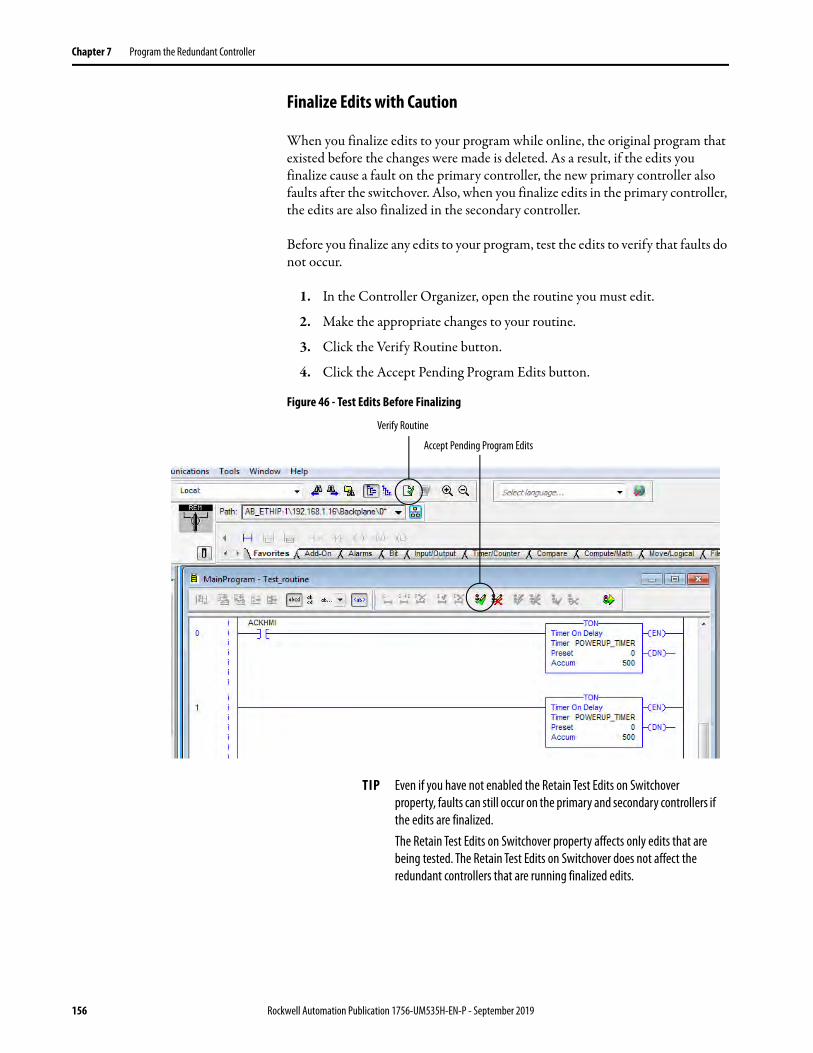
Chapter 7 Program the Redundant Controller
Finalize Edits with Caution
When you finalize edits to your program while online, the original program that existed before the changes were made is deleted. As a result, if the edits you finalize cause a fault on the primary controller, the new primary controller also faults after the switchover. Also, when you finalize edits in the primary controller, the edits are also finalized in the secondary controller.
Before you finalize any edits to your program, test the edits to verify that faults do not occur.
1. In the Controller Organizer, open the routine you must edit.
2. Make the appropriate changes to your routine.
3. Click the Verify Routine button.
4. Click the Accept Pending Program Edits button.
Figure 46 - Test Edits Before Finalizing
Accept Pending Program Edits
Verify Routine
TIP Even if you have not enabled the Retain Test Edits on Switchover property, faults can still occur on the primary and secondary controllers if the edits are finalized.The Retain Test Edits on Switchover property affects only edits that are being tested. The Retain Test Edits on Switchover does not affect the redundant controllers that are running finalized edits.
156 Rockwell Automation Publication 1756-UM535H-EN-P - September 2019

Program the Redundant Controller Chapter 7
5. At the Accept the Pending Edits dialog box, click Yes.
6. Click Test Accepted Program Edits.
7. At the dialog box, click Yes.
Test Accepted Program Edits
Rockwell Automation Publication 1756-UM535H-EN-P - September 2019 157
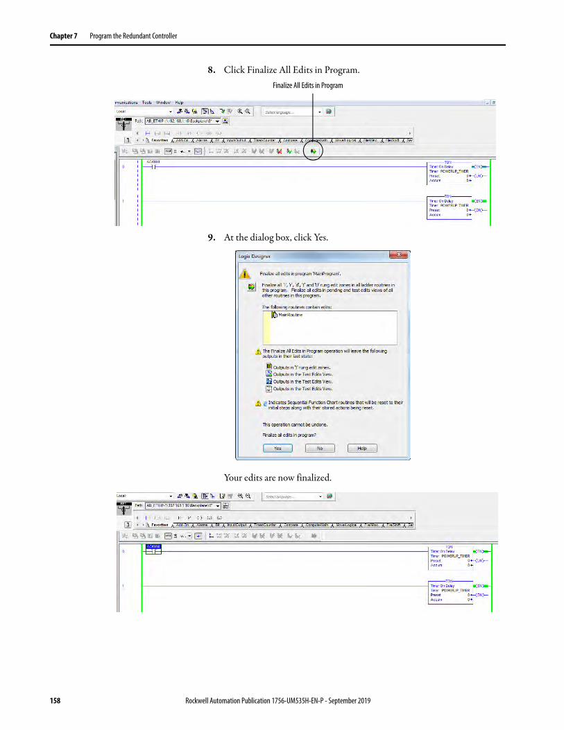
Chapter 7 Program the Redundant Controller
8. Click Finalize All Edits in Program.
9. At the dialog box, click Yes.
Your edits are now finalized.
Finalize All Edits in Program
158 Rockwell Automation Publication 1756-UM535H-EN-P - September 2019
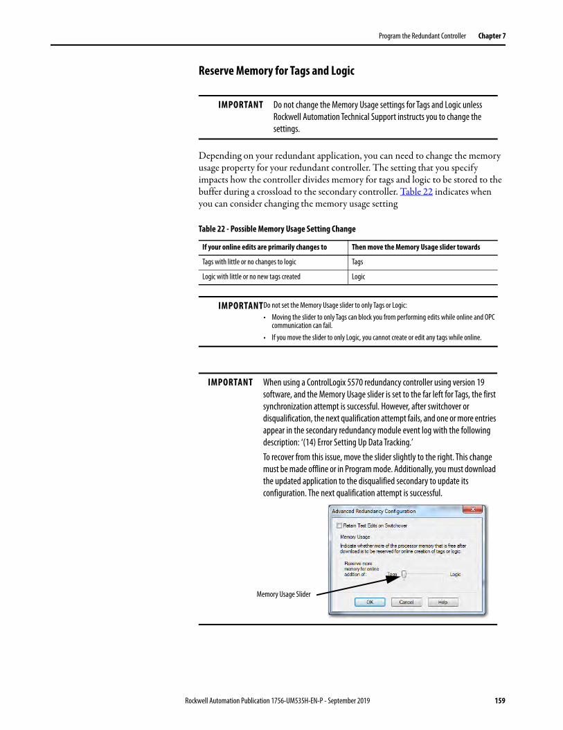
Program the Redundant Controller Chapter 7
Reserve Memory for Tags and Logic
Depending on your redundant application, you can need to change the memory usage property for your redundant controller. The setting that you specify impacts how the controller divides memory for tags and logic to be stored to the buffer during a crossload to the secondary controller. Table 22 indicates when you can consider changing the memory usage setting.
IMPORTANT Do not change the Memory Usage settings for Tags and Logic unless Rockwell Automation Technical Support instructs you to change the settings.
Table 22 - Possible Memory Usage Setting Change
If your online edits are primarily changes to Then move the Memory Usage slider towards
Tags with little or no changes to logic Tags
Logic with little or no new tags created Logic
IMPORTANTDo not set the Memory Usage slider to only Tags or Logic:• Moving the slider to only Tags can block you from performing edits while online and OPC
communication can fail.• If you move the slider to only Logic, you cannot create or edit any tags while online.
IMPORTANT When using a ControlLogix 5570 redundancy controller using version 19 software, and the Memory Usage slider is set to the far left for Tags, the first synchronization attempt is successful. However, after switchover or disqualification, the next qualification attempt fails, and one or more entries appear in the secondary redundancy module event log with the following description: ‘(14) Error Setting Up Data Tracking.’ To recover from this issue, move the slider slightly to the right. This change must be made offline or in Program mode. Additionally, you must download the updated application to the disqualified secondary to update its configuration. The next qualification attempt is successful.
Memory Usage Slider
Rockwell Automation Publication 1756-UM535H-EN-P - September 2019 159

Chapter 7 Program the Redundant Controller
Notes:
160 Rockwell Automation Publication 1756-UM535H-EN-P - September 2019

Chapter 8
Monitor and Maintain a Redundancy System
This chapter describes some of the key tasks to complete to monitor and maintain your redundancy system.
Controller Logging Beginning with redundancy system revision 19.052, you can use the controller logging feature. This feature provides a way to detect and log changes. These changes include programming software and controller mode switch interactions, made to ControlLogix® 5560 and ControlLogix 5570 controllers, without adding any auditing software.
With controller logging, the controller can perform these tasks:
• Detect changes and create logs entries that contain information about the changes.
• Store the log entries to a Compact FLASH (CF) card or Secure Digital (SD) card for later review.
• Provide programmatic access to log entry counters to provide change detection information remotely.
Topic Page
Controller Logging 161
Monitor System Status 163
Verify Date and Time Settings 165
Verify System Qualification 166
Check the EtherNet/IP Module Status 168
Check the ControlNet Module Status 170
Rockwell Automation Publication 1756-UM535H-EN-P - September 2019 161

Chapter 8 Monitor and Maintain a Redundancy System
Controller Log
A controller log is the record of changes. The log is stored on the NVS memory of the controller automatically. You can move the log to a CF card or SD card on an as needed basis or automatically at predefined times. The NVS memory of the controller and each external memory card type has a maximum number of entries that they can store.
Specific events are stored in the log of the controller.
For more information on controller logging, see the Logix 5000 Controllers Information and Status Programming Manual, publication 1756-PM015.
Controller Logging in Redundancy Systems
Because redundancy systems operate with partnered controllers, there are considerations that you must consider regarding controller logging:
• The primary and secondary controllers maintain separate logs.
• You do not need to synchronize the logs.
• On the primary controller, controller logging occurs exactly as it does on a controller in a non-redundant system, regardless of whether the system is qualified and synchronized or disqualified.
• A secondary controller logs the removal or insertion of removable storage components, that is, a CF or SD card, in any operating state. Otherwise, the secondary controller only logs events that occur when the controller is in a disqualified state.
Component Change Detection
Component tracking allows you to determine whether tracked routines, Add-On Instructions, and constant tags have been changed. The Studio 5000 Logix Designer® application creates a tracked value to indicate the current state of all components.
For more information, see the Logix 5000 Controllers Information and Status Programming Manual, publication 1756-PM015.
162 Rockwell Automation Publication 1756-UM535H-EN-P - September 2019

Monitor and Maintain a Redundancy System Chapter 8
Monitor System Status
For most redundant applications, you must program to obtain the status of the system. Program to obtain system status when you do the following:
• Program HMI to display the system status• Precondition logic to execute based on the system status• Use the diagnostic information to troubleshoot the system
To obtain the status of your redundant system, use a Get System Value (GSV) instruction in your program and plan for the tags you are writing the values to.
IMPORTANT When programming your redundancy system, program so your redundancy system status is continually monitored and displayed on your HMI device.If your redundancy system becomes disqualified or a switchover occurs, the change in status is not automatically annunciated. You must program the system to communicate the change in status via your HMI or other status-monitoring device.
Rockwell Automation Publication 1756-UM535H-EN-P - September 2019 163

Chapter 8 Monitor and Maintain a Redundancy System
In the following example, the GSV instruction is used to obtain the chassis ID (that is, the chassis A or B designation) of the chassis that is functioning as the primary. The PhysicalChassisID value is stored in the PRIM_Chassis_ID_Now tag. The PhysicalChassisID value that is retrieved matches the Chassis ID indicated in the Controller Properties dialog box.
Figure 47 - GSV Instruction to Get Chassis ID
For more information about the REDUNDANCY object attributes, see Appendix B, Redundancy Object Attributes on page 229.
If the Physical Chassis ID Value is Then the Chassis ID is
0 Unknown
1 Chassis A
2 Chassis B
Chassis ID in Controller Properties
Structured Text
Ladder Logic
164 Rockwell Automation Publication 1756-UM535H-EN-P - September 2019

Monitor and Maintain a Redundancy System Chapter 8
Verify Date and Time Settings
Verify that the Redundancy Module Date and Time information matches the date and time of your system after you have configured and downloaded your redundant system to the controller.
If the date and time are not correct, the redundant system event logs do not match the date and time information for the rest of the system. Incorrect date and time information complicates troubleshooting if an event or error occurs on your redundant system.
TIP Consider checking the Redundancy Module Date and Time as a part of your regular maintenance procedures. Regular verification of the date and time information keeps the event logs of the redundancy modules accurate.
Verify Date and Time Settings
2
IMPORTANT If power to one of the redundancy modules is cycled, the redundancy module powers up with the time set to when the power was lost. If the partner redundancy module has remained active during this time, the time set in that module is automatically transferred to the powering-up module. If a power failure event happens so that both modules are shut off, reset the time and date in the RMCT.If you set and verify the date and time settings after a power loss, it helps with troubleshooting if an error or event occurs.
Rockwell Automation Publication 1756-UM535H-EN-P - September 2019 165

Chapter 8 Monitor and Maintain a Redundancy System
Verify System Qualification After you have completed programming your redundant system and have downloaded your program to the primary controller, check the system status to verify that the system is qualified and synchronized.
Check Qualification Status Via Module Status Displays
You can view qualification status by using the status displays and indicators of the secondary redundancy module and the primary and secondary ControlNet® and EtherNet/IP™ communication modules.
TIP The system qualification process can take several minutes. After a qualification command or a switchover, allow time for qualification to complete before acting based on the qualification status.
Table 23 - Synchronized System
Primary Chassis Display Secondary Chassis Display
Redundancy Module Communication Module
Redundancy Module Communication Module
PRIM PwQS SYNC QS
Table 24 - Qualifying System
Primary Chassis Display Secondary Chassis Display
Redundancy Module Communication Module
Redundancy Module Communication Module
PRIM and QFNG PQgS QFNG QgS
Table 25 - System with a Primary and Disqualified Secondary
Primary Chassis Display Secondary Chassis Display
Redundancy Module Communication Module
Redundancy Module Communication Module
PRIM PwDS DISQ Either:• CMPT (modules are
compatible)• DSNP (no partner is
present)
166 Rockwell Automation Publication 1756-UM535H-EN-P - September 2019

Monitor and Maintain a Redundancy System Chapter 8
Example of Qualified and Disqualified Status Indicators
This example shows status display messages and status indicators that can appear differently depending on the qualification status of the redundant chassis. The following are only two examples of status display message and indicator combinations for both the qualified and disqualified states.
CH2 CH1 OK
CH2 CH1 OK
CH2 CH1 OK
CH2 CH1 OK
Qualified Redundant Chassis Disqualified Redundant Chassis
Primary Chassis
Secondary Chassis
Primary Chassis
Secondary Chassis
Rockwell Automation Publication 1756-UM535H-EN-P - September 2019 167

Chapter 8 Monitor and Maintain a Redundancy System
Check Qualification Status Via the RMCT
To determine the qualification status of your system by using the RMCT, open the RMCT and view the qualification status in the bottom-left corner of the tool.
Check the EtherNet/IP Module Status
After you have programmed your redundant system and configured your EtherNet/IP network, check two statistics specific to your EtherNet/IP modules. These statistics include the CPU usage and the connections used.
To view the CPU usage and the number of connections that are used, complete these steps.
1. In RSLinx® Classic software, open the Module Statistics for the EtherNet/IP module.
2. Click the Connection Manager tab.
168 Rockwell Automation Publication 1756-UM535H-EN-P - September 2019
Monitor and Maintain a Redundancy System Chapter 8
CPU Usage
The CPU usage of the EtherNet/IP modules must be at 80%, or less. CPU usage below 80% reserves enough CPU functionality for the EtherNet/IP module to facilitate a switchover.
If the CPU usage is above 80%, the secondary chassis can fail to synchronize with the primary chassis after a switchover occurs. In addition, unscheduled communication can be slowed.
If you must reduce the CPU usage of your EtherNet/IP modules, consider making the following changes:
• Adjust the Requested Packet Interval (RPI) of your connections.• Reduce the number of devices that are connected to your module.• Take steps to reduce your CPU utilization. See the EtherNet/IP Network
Configuration User Manual, publication ENET-UM001.
Connections Used
If the connections of your EtherNet/IP modules that are used are near the limits of the module, you can experience difficulty when attempting to go online with the system. This difficulty arises because going online with a processor also consumes a connection, if the attempts to go online are through the communication module that is near the limit. You can also experience difficulty when attempting to add modules to the system.
Monitor the EtherNet/IP Network
For most redundant applications, monitoring the status of the EtherNet/IP network is important for maintenance and troubleshooting.
Rockwell Automation Publication 1756-UM535H-EN-P - September 2019 169
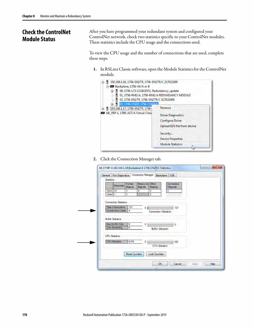
Chapter 8 Monitor and Maintain a Redundancy System
Check the ControlNet Module Status
After you have programmed your redundant system and configured your ControlNet network, check two statistics specific to your ControlNet modules. These statistics include the CPU usage and the connections used.
To view the CPU usage and the number of connections that are used, complete these steps.
1. In RSLinx Classic software, open the Module Statistics for the ControlNet module.
2. Click the Connection Manager tab.
170 Rockwell Automation Publication 1756-UM535H-EN-P - September 2019

Monitor and Maintain a Redundancy System Chapter 8
CPU Usage
The CPU usage of the ControlNet modules must be at 80%, or less. CPU usage below 80% reserves enough CPU functionality for the ControlNet module to facilitate a switchover.
If the CPU usage is above 80%, the secondary chassis can fail to synchronize with the primary chassis after a switchover occurs. In addition, unscheduled communication can be slowed.
If you must reduce the CPU usage of your ControlNet modules, consider making the following changes:
• Increase the Network Update Time (NUT) of the ControlNet network.• Increase the Requested Packet Interval (RPI) of your connections.• Reduce the number of connections through the ControlNet modules.• Reduce the number of messages that are used in the program.
Connections Used
If the connections of your ControlNet modules that are used are near the limits of the module, you can experience difficulty when attempting to go online with the system. This difficulty arises because going online with a processor also consumes a connection. You can also experience difficulty when attempting to add modules to the system.
For information about connections available with ControlNet modules, see ControlNet Network Requirements on page 30.
Monitor the ControlNet Network
For most redundant applications, monitoring the status of the ControlNet network is important for maintenance and troubleshooting.
For programming samples to monitor the ControlNet network, visit the Rockwell Automation® Sample Code Library athttp://samplecode.rockwellautomation.com. Applicable sample programs include the following:
• ME Faceplates for ControlNet Diagnostics• ControlNet Connection and Media Status
Rockwell Automation Publication 1756-UM535H-EN-P - September 2019 171

Chapter 8 Monitor and Maintain a Redundancy System
Notes:
172 Rockwell Automation Publication 1756-UM535H-EN-P - September 2019

Chapter 9
Troubleshoot a Redundant System
General Troubleshooting Tasks
When an error or other event occurs on the redundancy system, several tasks can be executed to determine the cause. After an error or event, you can perform these tasks:
• Check the module status indicators.
• View diagnostic information in the programming software.
• Access status and event information in the RMCT.
• Use RSLinx® Classic software to view network status.
• Use RSNetWorx™ for ControlNet® software to view ControlNet network status.
Topic Page
General Troubleshooting Tasks 173
Check the Module Status Indicators 174
Use Programming Software to View Errors 175
Event Log Tab 178
System Event History 188
Use the RMCT for Synchronization Attempts and Status 192
Use the RMCT Event Log 194
Keeper Status Causing Synchronize Failure 203
Partner Network Connection Lost 206
Redundancy Module Connection Lost 208
Redundancy Module Missing 209
Qualification Aborted Due to a Non-redundant Controller 210
Redundancy Module Status Indicators 211
Rockwell Automation Publication 1756-UM535H-EN-P - September 2019 173

Chapter 9 Troubleshoot a Redundant System
Check the Module Status Indicators
If an error or event occurs in the redundancy system, check the module status indicators to determine which module is causing the error or event.
If any of the modules have status indicators that are steady or blinking red, then examine that module status display and the RMCT or other software to determine the cause.
Figure 48 - Steady or Flashing Red Indicators Indicate Errors on 1756-RM2 or 1756-RM2XT Modules
Figure 49 - Steady of Flashing Red Indicators Indicate Errors on 1756-RM/1756-RMXT Modules
For more information about module status indicators, see Redundancy Module Status Indicators on page 211.
Figure 50 - Module Status Displays for Chassis with ControlLogix 5560 and ControlLogix 5570 Controllers
CH2 CH1 OK
PRI COM OK CH2 CH1 OK
ControlLogix® 5560 Controller and 1756-RM Module ControlLogix 5560 Controller and 1756-RM2 Module
CH2 CH1 OKPRI COM OK
ControlLogix 5570 Controller and 1756-RM Module ControlLogix 5570 Controller and 1756-RM2 Module
174 Rockwell Automation Publication 1756-UM535H-EN-P - September 2019

Troubleshoot a Redundant System Chapter 9
Use Programming Software to View Errors
To view redundancy status by using programming software, complete these steps.
1. Go online with the redundant controller.
2. Either click Primary or Secondary, depending on the controller you are online with.
The redundant controller ID and status are displayed.
Primary Controller
Secondary Controller
Rockwell Automation Publication 1756-UM535H-EN-P - September 2019 175

Chapter 9 Troubleshoot a Redundant System
3. If further information is required, click Controller Properties.
4. Click the Redundancy tab.
5. If controller fault details are needed, click the Major Faults and Minor Faults tabs to view fault types and codes.
These fault bits are status bits that the controller sets. You can set these fault bits for testing, but that is not the main purpose of these bits.
6. If necessary, reference these resources:
• Redundant Controller Major Fault Codes
• Logix 5000™ Controllers Major and Minor Faults Programming Manual, publication 1756-PM014 (describes all major and minor fault codes)
Fault details display here:
176 Rockwell Automation Publication 1756-UM535H-EN-P - September 2019
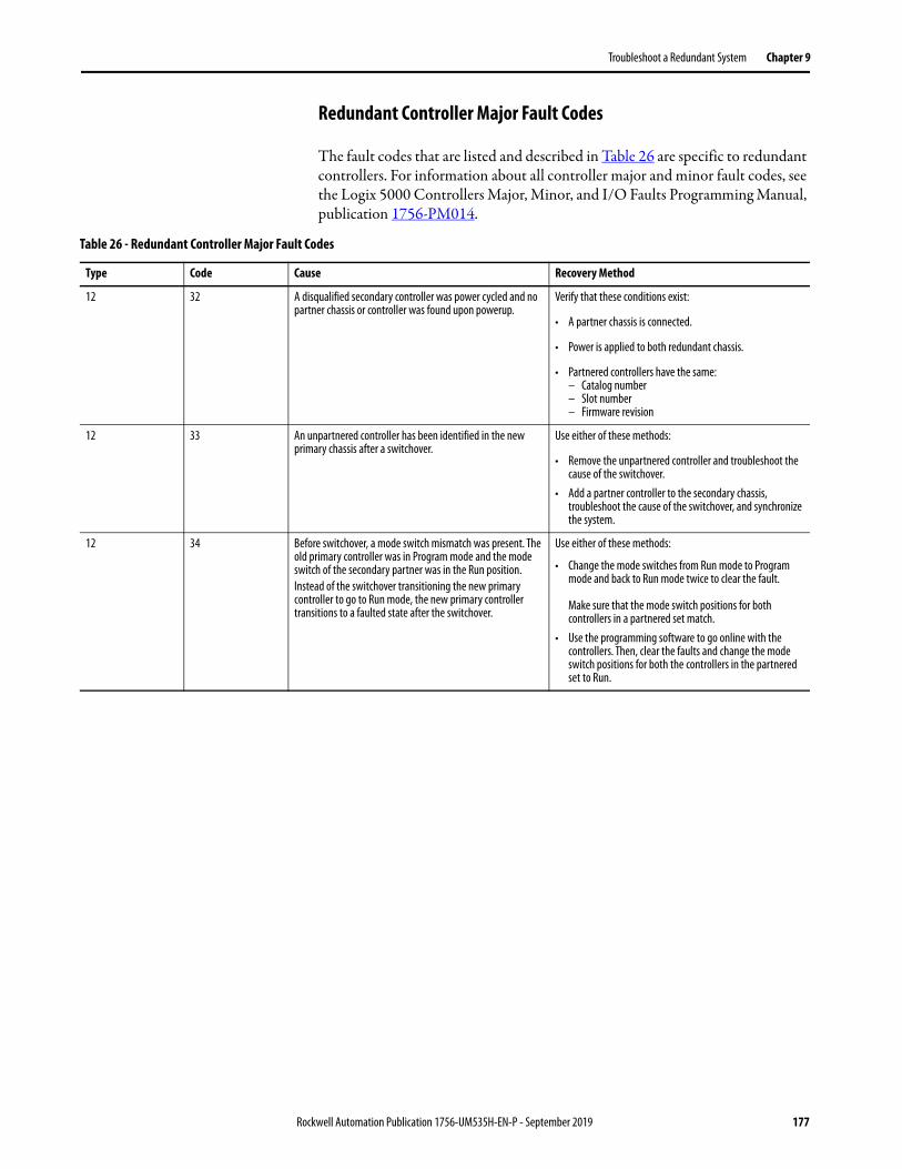
Troubleshoot a Redundant System Chapter 9
Redundant Controller Major Fault Codes
The fault codes that are listed and described in Table 26 are specific to redundant controllers. For information about all controller major and minor fault codes, see the Logix 5000 Controllers Major, Minor, and I/O Faults Programming Manual, publication 1756-PM014.
Table 26 - Redundant Controller Major Fault Codes
Type Code Cause Recovery Method
12 32 A disqualified secondary controller was power cycled and no partner chassis or controller was found upon powerup.
Verify that these conditions exist:
• A partner chassis is connected.
• Power is applied to both redundant chassis.
• Partnered controllers have the same:– Catalog number– Slot number– Firmware revision
12 33 An unpartnered controller has been identified in the new primary chassis after a switchover.
Use either of these methods:
• Remove the unpartnered controller and troubleshoot the cause of the switchover.
• Add a partner controller to the secondary chassis, troubleshoot the cause of the switchover, and synchronize the system.
12 34 Before switchover, a mode switch mismatch was present. The old primary controller was in Program mode and the mode switch of the secondary partner was in the Run position. Instead of the switchover transitioning the new primary controller to go to Run mode, the new primary controller transitions to a faulted state after the switchover.
Use either of these methods:
• Change the mode switches from Run mode to Program mode and back to Run mode twice to clear the fault.
Make sure that the mode switch positions for both controllers in a partnered set match.
• Use the programming software to go online with the controllers. Then, clear the faults and change the mode switch positions for both the controllers in the partnered set to Run.
Rockwell Automation Publication 1756-UM535H-EN-P - September 2019 177
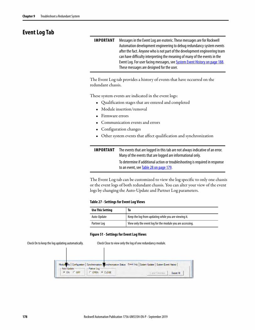
Chapter 9 Troubleshoot a Redundant System
Event Log Tab
The Event Log tab provides a history of events that have occurred on the redundant chassis.
These system events are indicated in the event logs:• Qualification stages that are entered and completed• Module insertion/removal• Firmware errors• Communication events and errors• Configuration changes• Other system events that affect qualification and synchronization
The Event Log tab can be customized to view the log specific to only one chassis or the event logs of both redundant chassis. You can alter your view of the event logs by changing the Auto-Update and Partner Log parameters.
Figure 51 - Settings for Event Log Views
IMPORTANT Messages in the Event Log are esoteric. These messages are for Rockwell Automation development engineering to debug redundancy system events after the fact. Anyone who is not part of the development engineering team can have difficulty interpreting the meaning of many of the events in the Event Log. For user facing messages, see System Event History on page 188. These messages are designed for the user.
IMPORTANT The events that are logged in this tab are not always indicative of an error. Many of the events that are logged are informational only.To determine if additional action or troubleshooting is required in response to an event, see Table 28 on page 179.
Table 27 - Settings for Event Log Views
Use This Setting To
Auto-Update Keep the log from updating while you are viewing it.
Partner Log View only the event log for the module you are accessing.
Check On to keep the log updating automatically. Check Close to view only the log of one redundancy module.
178 Rockwell Automation Publication 1756-UM535H-EN-P - September 2019

Troubleshoot a Redundant System Chapter 9
Event Classifications
Each event that is identified and logged is classified. You can use these classifications to identify the severity of the event and determine if additional action is required.
Figure 52 - Event Classifications in the Event Log Tab
Use Table 28 to determine what an event classification indicates and if corrective action is required.
Event Classifications
Table 28 - Classification Types
Classification Type Description Action Required
Configuration A redundancy module configuration parameter has been changed.For example, if you change the Auto-Synchronization parameter from Always to Never, an event that is classified as Configuration is logged.
No corrective action is required. This event is provided for informational purposes and does not indicate serious anomaly with the redundancy system.
Command An event that is related to commands that are issued to the redundant system has occurred.For example, if you change the Redundancy Module Date and Time parameters, a WCT time change event of the Command classification is logged.
No corrective action is required.This event is provided for informational purposes and does not indicate serious anomaly with the redundancy system.
Failure A failure on the redundancy module has occurred.For example, an internal Firmware error event that is classified as a Failure can be indicated in the event log.
Action can be required to determine the cause of the failure.If Switchover or Major Fault event does not precede a failure, then the module could have corrected the error internally and additional action is not required.To determine if corrective action is required, double-click the event to see Extended Event Information and the suggested recovery method, if applicable.
Major Fault A major fault has occurred on one of the redundancy modules. Action can be required to determine the action that is necessary to correct the fault. Double-click the event to see Extended Event Information and the suggested recovery method, if applicable.
Rockwell Automation Publication 1756-UM535H-EN-P - September 2019 179

Chapter 9 Troubleshoot a Redundant System
Minor Fault A minor fault has occurred on one of the redundancy modules. No corrective action is required. This event is provided for informational purposes and does not indicate a serious anomaly with the redundancy system.
Starts/Stops Various internal chassis and module processes have started or stopped. No corrective action is required.However, if an event that is classified as a Failure, State Change, or Major Fault occurs after the Starts/Stops event, view the Extended Event Information of both events to determine if the events are related.
State Changes A chassis or module state change has occurred.For example, if the chassis designation changes from being a disqualified secondary to a qualified secondary, a State Change event is logged.
No corrective action is required.However, if an event that is classified as a Failure, or Major Fault occurs after the State Changes event, view the Extended Event Information of both events to determine if the events are related.
Switchover An event that is related to a chassis switchover has occurred.For example, if an Initiate Switchover command is issued, an event that is classified as Switchover is logged.
Action can be required to determine the cause of the switchover and potential correction methods. Double-click the event to see Extended Event Information and the suggested recovery method, if applicable.
Synchronization An event that is related to chassis synchronization has occurred.For example, if the Synchronization command has been issued, a Network Transitioned to Attached event is logged and classified as Synchronization.
No corrective action is required.This event is provided for informational purposes and does not indicate a serious anomaly with the redundancy system.
Table 28 - Classification Types
Classification Type Description Action Required
180 Rockwell Automation Publication 1756-UM535H-EN-P - September 2019

Troubleshoot a Redundant System Chapter 9
Access Extended Information about an Event
Events that are logged in the Event Log tab can have additional information available. To access additional information about an event, double-click an event that is listed in the log.
Double-click to open extended information.
Scroll to view details of other events.
View the Description and Extended Data Definitions.
Rockwell Automation Publication 1756-UM535H-EN-P - September 2019 181

Chapter 9 Troubleshoot a Redundant System
Interpret Extended Information for an Event
The information that is listed in this table can be provided (depending on the type of event) after you have accessed the Extended Information Definition dialog box..
Export Event Log Data
After you have viewed extended information about an event, you could need to export event data. You can export data with either of these features:
• Export Selection
• Export All - Available with redundancy system, Revision 19.052 or later
Export Selection
Use this feature to export event log data for single or multiple events that occur on a primary or secondary redundancy module.
Complete these steps to export event data for an event.
1. Launch RSLinx Classic communication software and browse to the redundancy modules.
2. Right-click the primary redundancy module and choose Module Configuration.
Information Type Description
Event Information The redundancy system assigns this event information:• Event number• Date and time the event occurred• Event classification
Submitter Information This information reflects information specific to the module that reported the event. Information that is provided in this section includes the:• Name of the module that originated the event• Slot number of the module that originated the event• Serial number of the module that originated the event
Event Details This section provides these additional details about the event:• Description of the event• Examine the Extended Data Definition, which provides an explanation of the
event and bytes, for errors• Extended Data Bytes (in Hexadecimal) that provides further details the
event
TIP If the redundancy modules are not available in RSLinx Classic software after a fault, you must apply the recovery method that the module indicates before attempting to export the Event Log data.
182 Rockwell Automation Publication 1756-UM535H-EN-P - September 2019
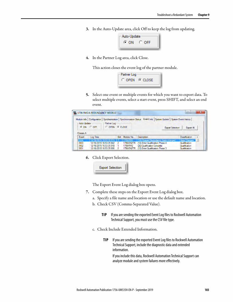
Troubleshoot a Redundant System Chapter 9
3. In the Auto-Update area, click Off to keep the log from updating.
4. In the Partner Log area, click Close.
This action closes the event log of the partner module.
5. Select one event or multiple events for which you want to export data. To select multiple events, select a start event, press SHIFT, and select an end event.
6. Click Export Selection.
The Export Event Log dialog box opens.
7. Complete these steps on the Export Event Log dialog box.a. Specify a file name and location or use the default name and location.b. Check CSV (Comma-Separated Value).
c. Check Include Extended Information.
TIP If you are sending the exported Event Log files to Rockwell Automation Technical Support, you must use the CSV file type.
TIP If you are sending the exported Event Log files to Rockwell Automation Technical Support, include the diagnostic data and extended information.If you include this data, Rockwell Automation Technical Support can analyze module and system failures more effectively.
Rockwell Automation Publication 1756-UM535H-EN-P - September 2019 183

Chapter 9 Troubleshoot a Redundant System
8. Click Export.
The event log is exported. The log can take a few minutes to export.
9. If you want to export the secondary redundancy module log for a complete system view complete step 1…step 8.
IMPORTANT If you are exporting event data to provide to Rockwell Automation Technical Support to troubleshoot an anomaly, you must obtain the event logs for both the primary and secondary redundancy modules. Rockwell Automation Technical Support needs the event logs to troubleshoot the anomaly.If you cannot access the event log for the secondary redundancy module, export it from the partner event log via the primary redundancy module. We recommend that you get the logs by choosing export all with the CSV file type.Keep in mind, though, that the view the primary redundancy module has of the event log of the secondary redundancy module is typically limited. To troubleshoot an anomaly with Rockwell Automation Technical Support, you must obtain the event log of the secondary redundancy module from the view of the module itself.
184 Rockwell Automation Publication 1756-UM535H-EN-P - September 2019

Troubleshoot a Redundant System Chapter 9
Export All
Use this feature to export all available event log data for events in both of the redundancy modules of the redundant chassis pair automatically.
We recommend that you use this feature when troubleshooting system-related anomalies, where the location of a fault could have occurred a lengthy period before the current event.
Complete these steps to export event log data for one event.
1. Launch RSLinx Classic communication software and browse to the redundancy modules.
2. Right-click the primary redundancy module and choose Module Configuration.
3. On the Event Log tab, click Export All.
4. At the Export All dialog box, click OK.
5. At the RSLinx Classic window, select the redundancy module in the partner redundant chassis.
6. Complete these steps on the Export Event Log dialog box and click OK.a. Specify a file name and location or use the default name and location.b. Check CSV (Comma-Separated Value).
c. Check Export Diagnostic Data.d. Check Include Extended Information.
TIP If the redundancy modules are not available in RSLinx Classic software after a fault, you must apply the recovery method that the module indicates before attempting to export the Event Log data.
TIP If you are sending the exported Event Log files to Rockwell Automation Technical Support, you must use the CSV file type.
TIP If you are sending the exported Event Log files to Rockwell Automation Technical Support, include the diagnostic data and extended information.If you include this data, Rockwell Automation Technical Support can analyze module and system failures more effectively.
Rockwell Automation Publication 1756-UM535H-EN-P - September 2019 185

Chapter 9 Troubleshoot a Redundant System
7. Click Export.
The event log is exported. The log can take a few minutes to export.
Wait for this dialog box to appear.
8. Click OK.
A .csv and a .dbg file is in the folder location specified. Make sure to provide the .csv file to Rockwell Automation Technical Support when troubleshooting an anomaly.
186 Rockwell Automation Publication 1756-UM535H-EN-P - September 2019

Troubleshoot a Redundant System Chapter 9
Clear a Fault
You can use the Clear Fault feature on the Event Log tab to clear major faults that occur on a redundancy module.
With this feature, you can remotely restart the redundancy module without physically removing and reinserting it from the chassis. The module restart clears the fault.
Module faults are displayed on the Module Info tab. This example graphic shows information for a module that has experienced a minor fault.
IMPORTANT Export all event and diagnostic data from the module before you clear major faults from the module. Clear Fault is active only when the redundancy module is in a major faulted state.
Fault details display here:
Rockwell Automation Publication 1756-UM535H-EN-P - September 2019 187
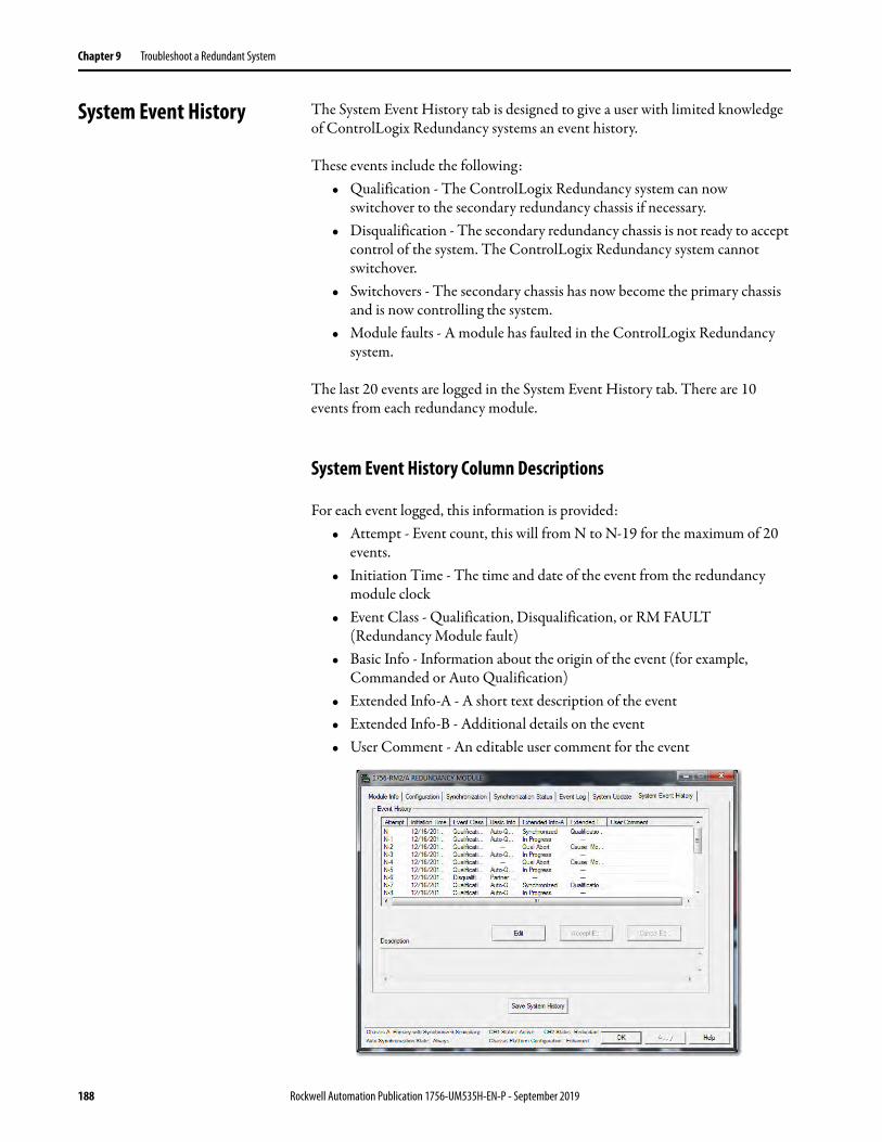
Chapter 9 Troubleshoot a Redundant System
System Event History The System Event History tab is designed to give a user with limited knowledge of ControlLogix Redundancy systems an event history.
These events include the following:• Qualification - The ControlLogix Redundancy system can now
switchover to the secondary redundancy chassis if necessary.• Disqualification - The secondary redundancy chassis is not ready to accept
control of the system. The ControlLogix Redundancy system cannot switchover.
• Switchovers - The secondary chassis has now become the primary chassis and is now controlling the system.
• Module faults - A module has faulted in the ControlLogix Redundancy system.
The last 20 events are logged in the System Event History tab. There are 10 events from each redundancy module.
System Event History Column Descriptions
For each event logged, this information is provided:• Attempt - Event count, this will from N to N-19 for the maximum of 20
events.• Initiation Time - The time and date of the event from the redundancy
module clock• Event Class - Qualification, Disqualification, or RM FAULT
(Redundancy Module fault)• Basic Info - Information about the origin of the event (for example,
Commanded or Auto Qualification)• Extended Info-A - A short text description of the event• Extended Info-B - Additional details on the event• User Comment - An editable user comment for the event
188 Rockwell Automation Publication 1756-UM535H-EN-P - September 2019
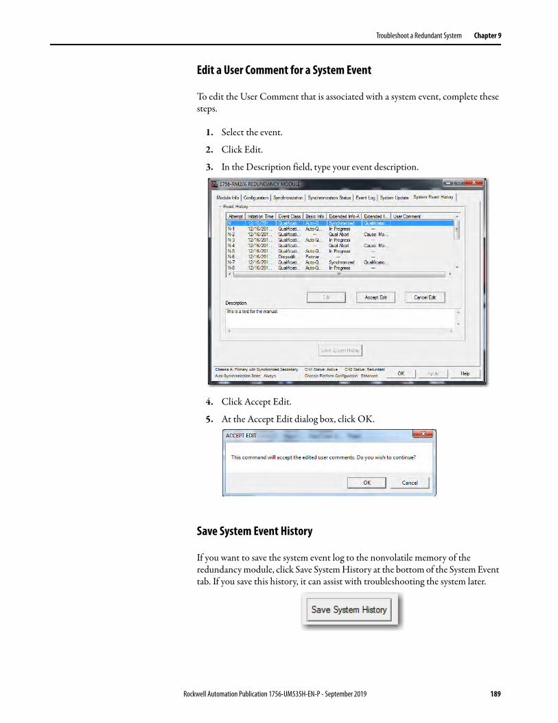
Troubleshoot a Redundant System Chapter 9
Edit a User Comment for a System Event
To edit the User Comment that is associated with a system event, complete these steps.
1. Select the event.
2. Click Edit.
3. In the Description field, type your event description.
4. Click Accept Edit.
5. At the Accept Edit dialog box, click OK.
Save System Event History
If you want to save the system event log to the nonvolatile memory of the redundancy module, click Save System History at the bottom of the System Event tab. If you save this history, it can assist with troubleshooting the system later.
Rockwell Automation Publication 1756-UM535H-EN-P - September 2019 189
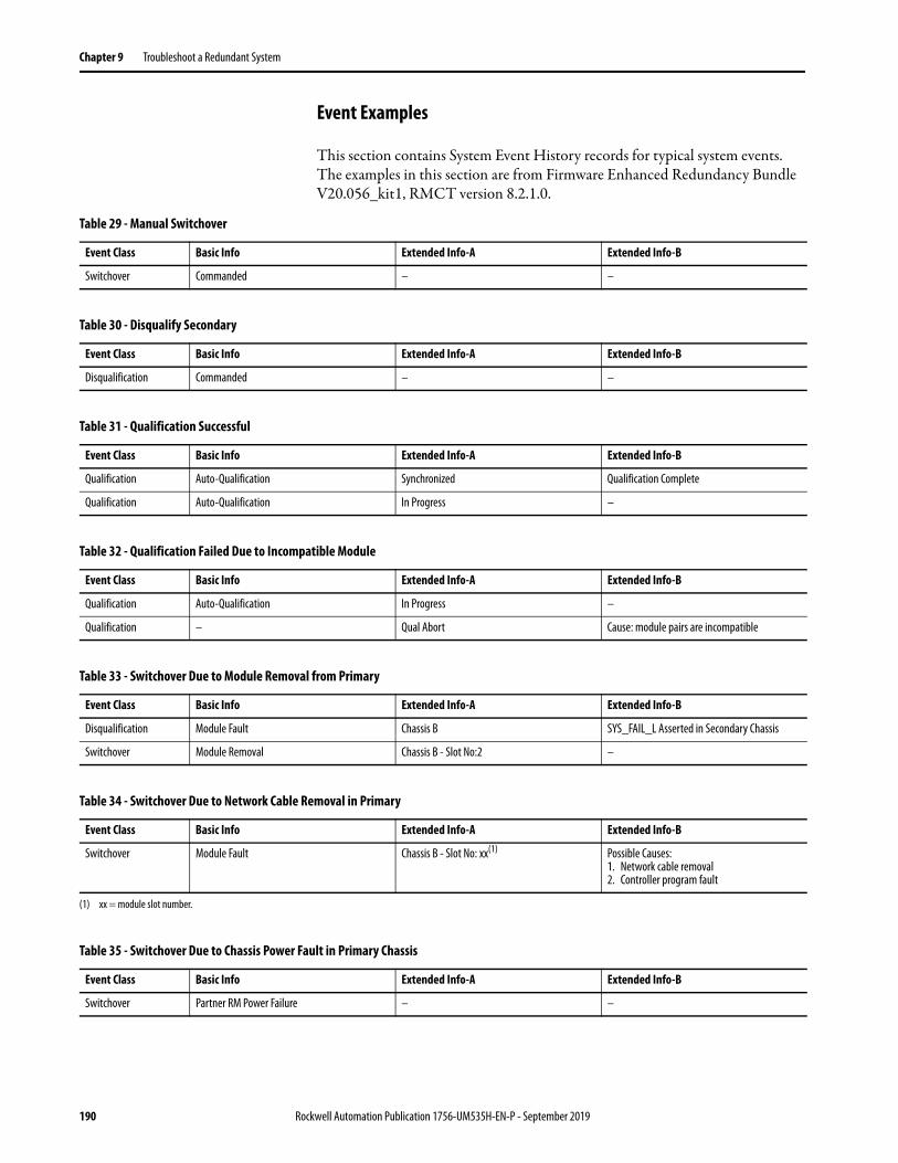
Chapter 9 Troubleshoot a Redundant System
Event Examples
This section contains System Event History records for typical system events. The examples in this section are from Firmware Enhanced Redundancy Bundle V20.056_kit1, RMCT version 8.2.1.0.
Table 29 - Manual Switchover
Event Class Basic Info Extended Info-A Extended Info-B
Switchover Commanded – –
Table 30 - Disqualify Secondary
Event Class Basic Info Extended Info-A Extended Info-B
Disqualification Commanded – –
Table 31 - Qualification Successful
Event Class Basic Info Extended Info-A Extended Info-B
Qualification Auto-Qualification Synchronized Qualification Complete
Qualification Auto-Qualification In Progress –
Table 32 - Qualification Failed Due to Incompatible Module
Event Class Basic Info Extended Info-A Extended Info-B
Qualification Auto-Qualification In Progress –
Qualification – Qual Abort Cause: module pairs are incompatible
Table 33 - Switchover Due to Module Removal from Primary
Event Class Basic Info Extended Info-A Extended Info-B
Disqualification Module Fault Chassis B SYS_FAIL_L Asserted in Secondary Chassis
Switchover Module Removal Chassis B - Slot No:2 –
Table 34 - Switchover Due to Network Cable Removal in Primary
Event Class Basic Info Extended Info-A Extended Info-B
Switchover Module Fault Chassis B - Slot No: xx(1) Possible Causes: 1. Network cable removal2. Controller program fault
(1) xx = module slot number.
Table 35 - Switchover Due to Chassis Power Fault in Primary Chassis
Event Class Basic Info Extended Info-A Extended Info-B
Switchover Partner RM Power Failure – –
190 Rockwell Automation Publication 1756-UM535H-EN-P - September 2019

Troubleshoot a Redundant System Chapter 9
Table 36 - Disqualification Due to Network Connection Lost between Primary and Secondary Chassis
Event Class Basic Info Extended Info-A Extended Info-B
Switchover Module Fault Chassis B - Slot No: xx(1) Possible Causes:1. Network Cable Removal(2)
2. Controller Program Fault
(1) xx = module slot number.(2) This lost connection is not a network cable removal issue. The communication modules not being able to see each other over the network has caused the lost connection.
Table 37 - Disqualification Due to Partner Chassis Power Fault
Event Class Basic Info Extended Info-A Extended Info-B
Disqualification Partner RM Power Failure – –
Table 38 - Disqualification Due to Partner Chassis Module Removal
Event Class Basic Info Extended Info-A Extended Info-B
Disqualification Module Removal Chassis A - Slot No: xx(1) –
(1) xx = module slot number.
Table 39 - Disqualification Due to Partner Chassis Redundancy Module Fault
Event Class Basic Info Extended Info-A Extended Info-B
RM FAULT Major Fault Fault Code: EE05 Reset
Disqualification Partner RM Power Failure – –
Table 40 - Disqualification Due to Redundancy Module Fiber Cable Disconnected or Faulted
Event Class Basic Info Extended Info-A Extended Info-B
Disqualification RM Fiber Cable Disconnect – –
Rockwell Automation Publication 1756-UM535H-EN-P - September 2019 191
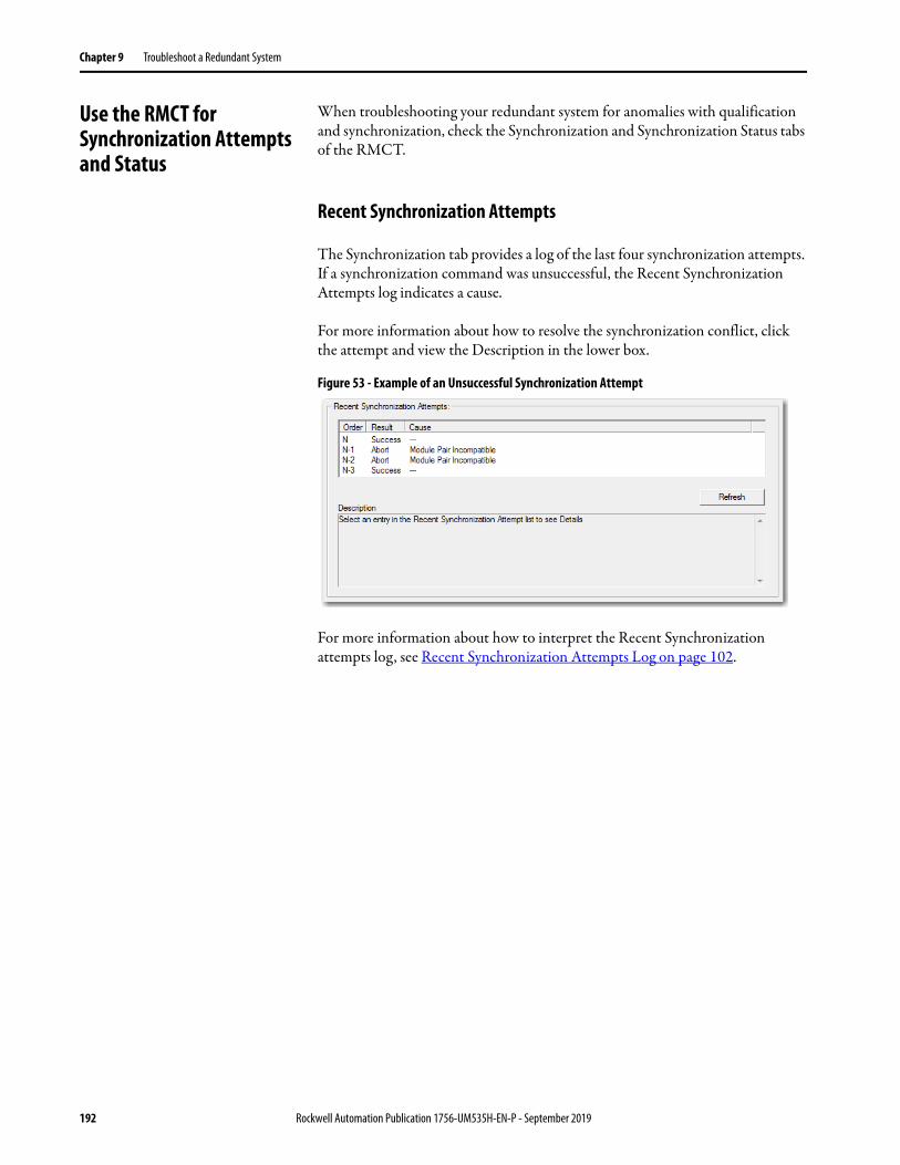
Chapter 9 Troubleshoot a Redundant System
Use the RMCT for Synchronization Attempts and Status
When troubleshooting your redundant system for anomalies with qualification and synchronization, check the Synchronization and Synchronization Status tabs of the RMCT.
Recent Synchronization Attempts
The Synchronization tab provides a log of the last four synchronization attempts. If a synchronization command was unsuccessful, the Recent Synchronization Attempts log indicates a cause.
For more information about how to resolve the synchronization conflict, click the attempt and view the Description in the lower box.
Figure 53 - Example of an Unsuccessful Synchronization Attempt
For more information about how to interpret the Recent Synchronization attempts log, see Recent Synchronization Attempts Log on page 102.
192 Rockwell Automation Publication 1756-UM535H-EN-P - September 2019

Troubleshoot a Redundant System Chapter 9
Module-level Synchronization Status
The Synchronization Status tab provides a module-level view of redundant chassis and can be used to identify what module pair can be causing a synchronization failure.
Depending on the type of synchronization failure, you can need to open the Synchronization Status tabs for the primary and secondary redundancy modules.
• If there is a difference between major revisions of the controllers or modules, the Compatibility column shows Incompatible, as shown in this graphic.
• If there is a difference between minor revisions of the controllers or modules, the Compatibility column also shows Incompatible, as shown in the following graphic.
Primary Chassis
Secondary Chassis
Primary Chassis
Secondary Chassis
Rockwell Automation Publication 1756-UM535H-EN-P - September 2019 193

Chapter 9 Troubleshoot a Redundant System
Use the RMCT Event Log When troubleshooting your redundant system, access the Event Log to determine the cause of an event, error, switchover, or major fault.
Interpret Event Log Information
Use this procedure to view and interpret Event Log information.
1. Open the RMCT and click the Event Log tab.
Primary Chassis
Secondary Chassis
194 Rockwell Automation Publication 1756-UM535H-EN-P - September 2019
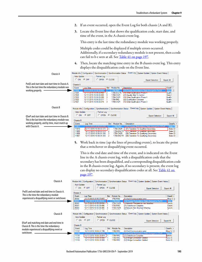
Troubleshoot a Redundant System Chapter 9
2. If an event occurred, open the Event Log for both chassis (A and B).
3. Locate the Event line that shows the qualification code, start date, and time of the event, in the A chassis event log.
This entry is the last time the redundancy module was working properly.
Multiple codes could be displayed if multiple errors occurred. Additionally, if a secondary redundancy module is not present, then a code can fail to b e seen at all. See Table 41 on page 197.
4. Then, locate the matching time entry in the B chassis event log. This entry displays the disqualification code on the Event line.
5. Work back in time (up the lines of preceding events), to locate the point that a switchover or disqualifying event occurred.
This is the end date and time of the event, and is indicated on the Event line in the A chassis event log, with a disqualification code that the secondary has been disqualified, and a corresponding disqualification code in the B chassis event log. Again, if no secondary is present, the event log can display no secondary disqualification codes at all. See Table 41 on page 197.
Chassis A
Chassis B
PwQS and start date and start time in Chassis A. This is the last time the redundancy module was working properly.
QSwP and start date and start time in Chassis B. This is the last time the redundancy module was working properly, and by time, must match up with Chassis A.
Chassis A
PwDS and end date and end time in Chassis A. This is the time the redundancy module experienced a disqualifying event or switchover.
DSwP and matching end date and end time in Chassis B. This is the time the redundancy module experienced a disqualifying event or switchover.
Chassis B
Rockwell Automation Publication 1756-UM535H-EN-P - September 2019 195

Chapter 9 Troubleshoot a Redundant System
6. To find the error that caused the disqualification, examine the range of time in between the start of the event and the end of the event.
IMPORTANT This range of time can be large depending on how much time has passed since the last disqualifying event.
Error
Error
Start
End
Start
End
TIP You can also use the Log Time column to identify a significant event. Scan within a time range that corresponds to the time an event was reported or annunciated.In addition, you can also attempt to identify events by finding differences between times logged. Such gaps in time often identify events that require troubleshooting. When troubleshooting by identifying gaps in the time entries, remember that gaps in months, days, or minutes can indicate a significant change to the system.Not all events that are logged are indicative of an anomaly that must be corrected. For example, events that are classified as Minor Faults do not warrant corrective behavior unless they occur just before a switchover, major fault, or state change and can be identified as contributing to successive events.
196 Rockwell Automation Publication 1756-UM535H-EN-P - September 2019

Troubleshoot a Redundant System Chapter 9
7. After you have located an event entry that is related to the anomaly you are troubleshooting, double-click the event to view Extended Event Information.
8. View the Description and Extended Data Definitions.
The Description and Extended Data Definitions can be used to obtain further event information and can indicate a recovery method.
Double-click to view more information.
The Description provides more information about the state change that occurred.
No recovery method is described. This indicates that action is not required in response to this event.
Table 41 - Possible Qualification Status Indicators
Status Code Description
PwQS Primary with qualified (synchronized) secondary partner
QSwP Qualified (synchronized) secondary with primary partner
DSwP Disqualified secondary with primary partner
DSwNP Disqualified secondary with no partner
PwDS Primary with disqualified secondary partner
PwNS Primary with no secondary partner
Rockwell Automation Publication 1756-UM535H-EN-P - September 2019 197

Chapter 9 Troubleshoot a Redundant System
Export All Event Logs
To export event logs with the RMCT version 8.3.1.0 or later, follow these steps.
1. Open the RMCT on the redundancy module in the primary chassis and click the Event Log tab.
2. Click Export All.
The Export All dialog box appears.
3. Click OK.
4. Select the communication path to the partner redundancy module with RSLinx Classic.
The Export Event Log configuration screen appears.
5. To change the file name or save location to something other than the default, select the Browse button.
6. Click Export.
198 Rockwell Automation Publication 1756-UM535H-EN-P - September 2019
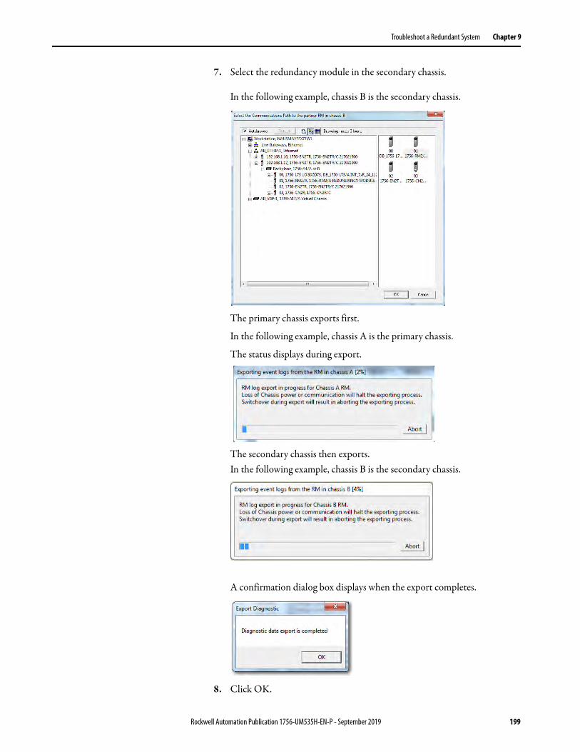
Troubleshoot a Redundant System Chapter 9
7. Select the redundancy module in the secondary chassis.
In the following example, chassis B is the secondary chassis.
The primary chassis exports first.
In the following example, chassis A is the primary chassis.
The status displays during export.
The secondary chassis then exports.In the following example, chassis B is the secondary chassis.
A confirmation dialog box displays when the export completes.
8. Click OK.
Rockwell Automation Publication 1756-UM535H-EN-P - September 2019 199
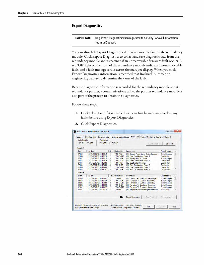
Chapter 9 Troubleshoot a Redundant System
Export Diagnostics
You can also click Export Diagnostics if there is a module fault in the redundancy module. Click Export Diagnostics to collect and save diagnostic data from the redundancy module and its partner, if an unrecoverable firmware fault occurs. A red ‘OK’ light on the front of the redundancy module indicates a nonrecoverable fault, and a fault message scrolls across the marquee display. When you click Export Diagnostics, information is recorded that Rockwell Automation engineering can use to determine the cause of the fault.
Because diagnostic information is recorded for the redundancy module and its redundancy partner, a communication path to the partner redundancy module is also part of the process to obtain the diagnostics.
Follow these steps.
1. Click Clear Fault if it is enabled, as it can first be necessary to clear any faults before using Export Diagnostics.
2. Click Export Diagnostics.
IMPORTANT Only Export Diagnostics when requested to do so by Rockwell Automation Technical Support.
200 Rockwell Automation Publication 1756-UM535H-EN-P - September 2019

Troubleshoot a Redundant System Chapter 9
The Export Diagnostics dialog box appears and asks you to continue specifying a communication path.
3. Click OK to specify the communication path via RSWho software.
The RSWho window appears.
4. Select the communication path to the partner or secondary module and click OK.
The Export Diagnostics dialog box appears and prompts you to specify a location to save the export file.
Rockwell Automation Publication 1756-UM535H-EN-P - September 2019 201
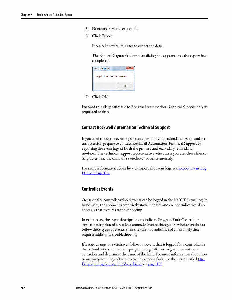
Chapter 9 Troubleshoot a Redundant System
5. Name and save the export file.
6. Click Export.
It can take several minutes to export the data.
The Export Diagnostic Complete dialog box appears once the export has completed.
7. Click OK.
Forward this diagnostics file to Rockwell Automation Technical Support only if requested to do so.
Contact Rockwell Automation Technical Support
If you tried to use the event logs to troubleshoot your redundant system and are unsuccessful, prepare to contact Rockwell Automation Technical Support by exporting the event logs of both the primary and secondary redundancy modules. The technical support representative who assists you uses those files to help determine the cause of a switchover or other anomaly.
For more information about how to export the event logs, see Export Event Log Data on page 182.
Controller Events
Occasionally, controller-related events can be logged in the RMCT Event Log. In some cases, the anomalies are strictly status updates and are not indicative of an anomaly that requires troubleshooting.
In other cases, the event description can indicate Program Fault Cleared, or a similar description of a resolved anomaly. If state changes or switchovers do not follow these types of events, then they are not indicative of an anomaly that requires additional troubleshooting.
If a state change or switchover follows an event that is logged for a controller in the redundant system, use the programming software to go online with the controller and determine the cause of the fault. For more information about how to use programming software to troubleshoot a fault, see the section titled Use Programming Software to View Errors on page 175.
202 Rockwell Automation Publication 1756-UM535H-EN-P - September 2019
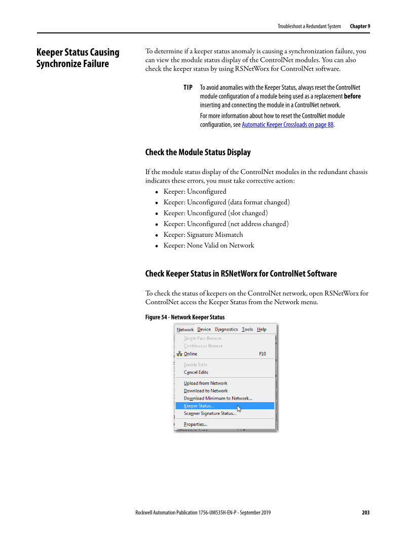
Troubleshoot a Redundant System Chapter 9
Keeper Status Causing Synchronize Failure
To determine if a keeper status anomaly is causing a synchronization failure, you can view the module status display of the ControlNet modules. You can also check the keeper status by using RSNetWorx for ControlNet software.
Check the Module Status Display
If the module status display of the ControlNet modules in the redundant chassis indicates these errors, you must take corrective action:
• Keeper: Unconfigured• Keeper: Unconfigured (data format changed)• Keeper: Unconfigured (slot changed)• Keeper: Unconfigured (net address changed)• Keeper: Signature Mismatch• Keeper: None Valid on Network
Check Keeper Status in RSNetWorx for ControlNet Software
To check the status of keepers on the ControlNet network, open RSNetWorx for ControlNet access the Keeper Status from the Network menu.
Figure 54 - Network Keeper Status
TIP To avoid anomalies with the Keeper Status, always reset the ControlNet module configuration of a module being used as a replacement before inserting and connecting the module in a ControlNet network. For more information about how to reset the ControlNet module configuration, see Automatic Keeper Crossloads on page 88.
Rockwell Automation Publication 1756-UM535H-EN-P - September 2019 203

Chapter 9 Troubleshoot a Redundant System
Valid Keepers and Signatures
This example shows a Keeper Status dialog box where the ControlNet network is composed of valid keepers and signatures.
Valid Keeper Status and Signatures
Unconfigured Keeper
The following example shows the Keeper Status dialog box where a module has an unconfigured status. Besides the status that is shown, the module status display indicates Keeper: Unconfigured (node address changed).
This error results when the node address of the module has been changed. After changing the node address, the module was used as a replacement and inserted into the redundant chassis.
Figure 55 - Keeper Status - Unconfigured
To correct this anomaly, do one of the following:• Select the unconfigured module and click Update Keeper.• Reschedule the ControlNet network.
204 Rockwell Automation Publication 1756-UM535H-EN-P - September 2019

Troubleshoot a Redundant System Chapter 9
Keeper Signature Mismatch
This example shows ControlNet modules in the redundant chassis that do not have the same keeper signatures. With this anomaly, the ControlNet module display indicates Keeper: Signature Mismatch.
This anomaly can result if a ControlNet module configured for the same node of another network is used to replace a ControlNet module with the same node address in the redundant chassis.
Figure 56 - Keeper Status - Signature Mismatch
To correct this anomaly, do one of the following:• Select the unconfigured module and click Update Keeper.• Reschedule the ControlNet network.
ControlNet modules in the redundant chassis with different keeper signatures.
Rockwell Automation Publication 1756-UM535H-EN-P - September 2019 205
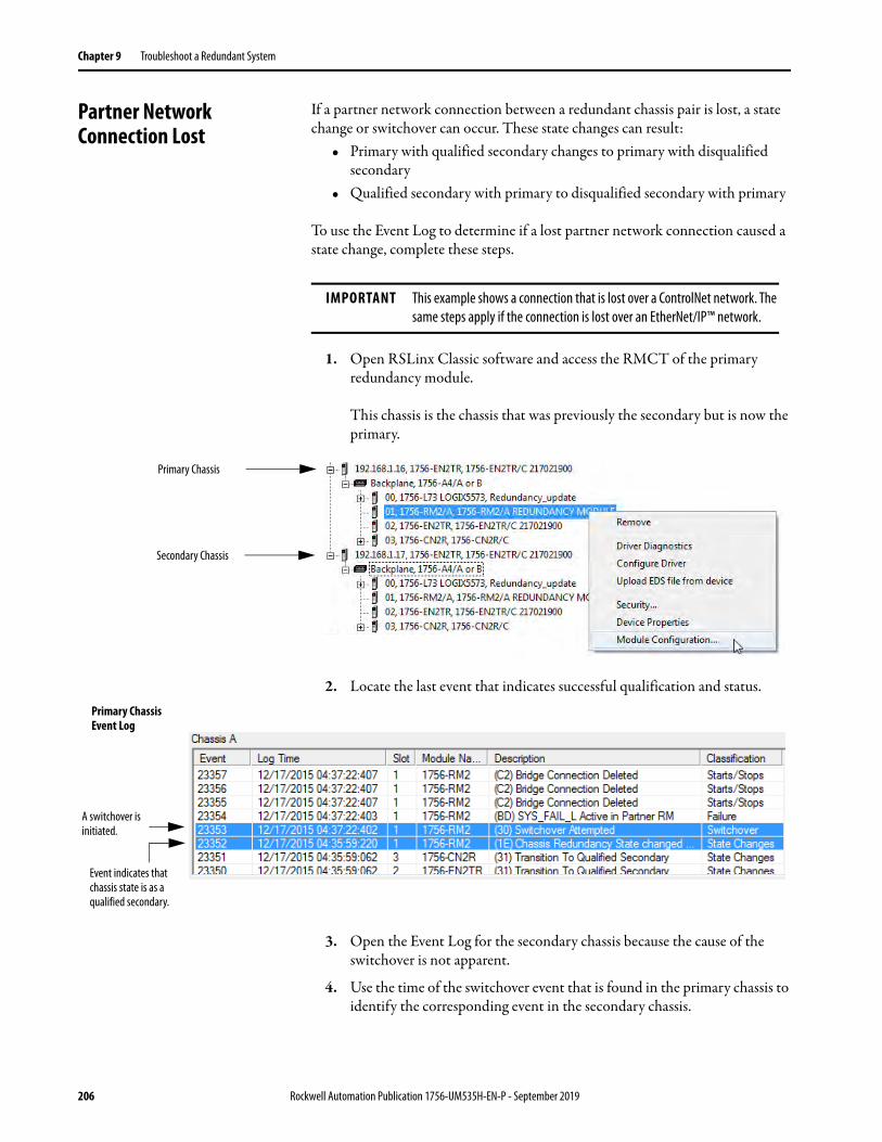
Chapter 9 Troubleshoot a Redundant System
Partner Network Connection Lost
If a partner network connection between a redundant chassis pair is lost, a state change or switchover can occur. These state changes can result:
• Primary with qualified secondary changes to primary with disqualified secondary
• Qualified secondary with primary to disqualified secondary with primary
To use the Event Log to determine if a lost partner network connection caused a state change, complete these steps.
1. Open RSLinx Classic software and access the RMCT of the primary redundancy module.
This chassis is the chassis that was previously the secondary but is now the primary.
2. Locate the last event that indicates successful qualification and status.
3. Open the Event Log for the secondary chassis because the cause of the switchover is not apparent.
4. Use the time of the switchover event that is found in the primary chassis to identify the corresponding event in the secondary chassis.
IMPORTANT This example shows a connection that is lost over a ControlNet network. The same steps apply if the connection is lost over an EtherNet/IP™ network.
Primary Chassis
Secondary Chassis
Primary Chassis Event Log
Event indicates that chassis state is as a qualified secondary.
A switchover is initiated.
206 Rockwell Automation Publication 1756-UM535H-EN-P - September 2019

Troubleshoot a Redundant System Chapter 9
The switchover indicated in the primary chassis log occurred at 04:37:22.
The corresponding events in the secondary chassis log indicate that the network is not attached and that the SYS_FAIL_LActive backplane signal is active. Both these events indicate an error in the connection of the ControlNet module to the network.
5. Confirm the ControlNet connection error by browsing the network in RSLinx Classic software.
Secondary Chassis Event Log
This node is no longer connected.
An attempt to access the secondary RMCT fails and this error is indicated.
Rockwell Automation Publication 1756-UM535H-EN-P - September 2019 207

Chapter 9 Troubleshoot a Redundant System
To recover from a ControlNet network disconnection, perform the following:• Check all ControlNet tap and trunkline connections. Correct any
disconnections or other connection anomalies.• If the Auto-Synchronization parameter is not set to Always, use the
commands in the Synchronization tab of the RMCT to synchronize your chassis.
For more information about troubleshooting ControlNet network anomalies, see the ControlNet Network Configuration User Manual, publication CNET-UM001.
To recover from a EtherNet/IP network disconnection, perform the following:• Check all EtherNet/IP network and switch connections.• If the Auto-Synchronization parameter is not set to Always, use the
commands in the Synchronization tab of the RMCT to synchronize your chassis.
For more information about troubleshooting EtherNet/IP network anomalies, see the EtherNet/IP Network Configuration User Manual, publication ENET-UM001.
Redundancy Module Connection Lost
To determine if the connection between the redundancy modules caused a switchover or state change, open the Event Log of the redundancy module that is the primary.
The Event Log clearly indicates that one of the redundancy modules has been disconnected. In addition, the dimmed secondary chassis log indicates that the module is not connected.
To resolve this anomaly, check the intermodule cable that connects the redundancy modules. Verify that it is properly connected and is not severed.
Also, if the Auto-Synchronization parameter of this system is not set to always, use the commands in the Synchronization tab to synchronize that chassis once the anomaly is resolved.
208 Rockwell Automation Publication 1756-UM535H-EN-P - September 2019

Troubleshoot a Redundant System Chapter 9
Redundancy Module Missing
To determine if a missing redundancy module caused a state change and switchover, access the Event Log of the chassis that is the primary chassis.
Figure 57 - Event Log with Partner RM Screamed Event
The redundancy module logs the Partner RM Screamed even just before it is disconnected. Depending on the cause of the missing module, the Partner RM Screamed event can fail to be logged before the module is lost.
You can also browse to the redundancy module in RSLinx Classic software to determine if it is connected to the network. A red X over the redundancy module indicates that the module is not in the chassis.
Figure 58 - Missing Redundancy Module in RSLinx Classic Software
To correct the missing module anomaly, first verify that the redundancy module is correctly installed in the chassis and it is properly powered. Then check the intermodule cable that connects the redundancy modules.
After you have verified that the module is installed and powered, you can need to synchronize the chassis by using the synchronization commands in the Synchronization tab. Use the synchronization commands if your Auto-Synchronization parameter for the chassis is not set to Always.
Last normal event logged.
RM Screamed event indicates module removal.
Dimmed secondary chassis log indicates issue with redundancy module.
Rockwell Automation Publication 1756-UM535H-EN-P - September 2019 209
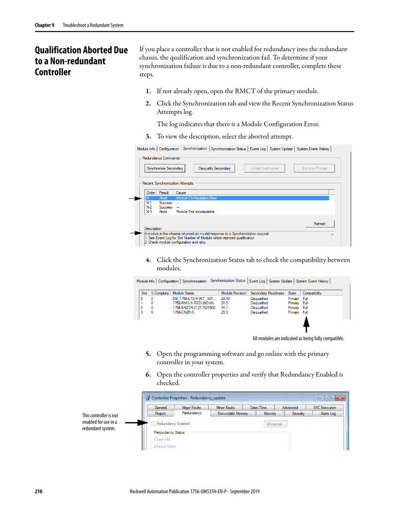
Chapter 9 Troubleshoot a Redundant System
Qualification Aborted Due to a Non-redundant Controller
If you place a controller that is not enabled for redundancy into the redundant chassis, the qualification and synchronization fail. To determine if your synchronization failure is due to a non-redundant controller, complete these steps.
1. If not already open, open the RMCT of the primary module.
2. Click the Synchronization tab and view the Recent Synchronization Status Attempts log.
The log indicates that there is a Module Configuration Error.
3. To view the description, select the aborted attempt.
4. Click the Synchronization Status tab to check the compatibility between modules.
5. Open the programming software and go online with the primary controller in your system.
6. Open the controller properties and verify that Redundancy Enabled is checked.
All modules are indicated as being fully compatible.
This controller is not enabled for use in a redundant system.
210 Rockwell Automation Publication 1756-UM535H-EN-P - September 2019
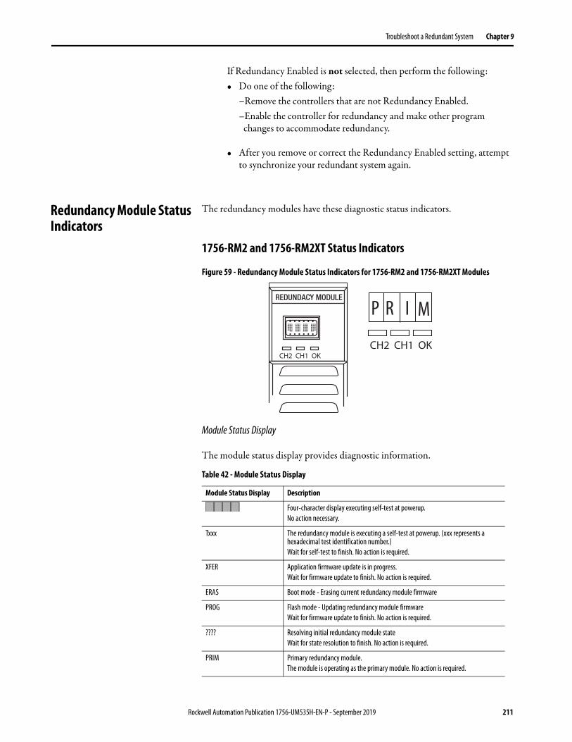
Troubleshoot a Redundant System Chapter 9
If Redundancy Enabled is not selected, then perform the following:• Do one of the following:
–Remove the controllers that are not Redundancy Enabled.–Enable the controller for redundancy and make other program
changes to accommodate redundancy.
• After you remove or correct the Redundancy Enabled setting, attempt to synchronize your redundant system again.
Redundancy Module Status Indicators
The redundancy modules have these diagnostic status indicators.
1756-RM2 and 1756-RM2XT Status Indicators
Figure 59 - Redundancy Module Status Indicators for 1756-RM2 and 1756-RM2XT Modules
Module Status Display
The module status display provides diagnostic information.
Table 42 - Module Status Display
Module Status Display Description
Four-character display executing self-test at powerup.No action necessary.
Txxx The redundancy module is executing a self-test at powerup. (xxx represents a hexadecimal test identification number.)Wait for self-test to finish. No action is required.
XFER Application firmware update is in progress.Wait for firmware update to finish. No action is required.
ERAS Boot mode - Erasing current redundancy module firmware
PROG Flash mode - Updating redundancy module firmwareWait for firmware update to finish. No action is required.
???? Resolving initial redundancy module stateWait for state resolution to finish. No action is required.
PRIM Primary redundancy module.The module is operating as the primary module. No action is required.
CH2 CH1 OKCH2 CH1 OK
P R I M
Rockwell Automation Publication 1756-UM535H-EN-P - September 2019 211

Chapter 9 Troubleshoot a Redundant System
DISQ Disqualified secondary redundancy module.Check the type and revision of the secondary partner module.
QFNG Qualifying secondary redundancy module.Redundant system status. No action is required.
SYNC Qualified secondary redundancy module.Redundant system status. No action is required.
LKNG Secondary redundancy module that is in process of locking for update.
LOCK Secondary redundancy module that is locked for update.
Exxx Major fault has occurred (xxx represents an error or fault code, with the two least-significant characters in decimal).Use the Error ID code to diagnose and address the error. For more information on error codes, see Redundancy Module Fault Codes and Display Messages on page 218.
EEPROM Update Required Onboard EEPROM is empty.Replace the module.
BOOT Erase Error Error in erasing NVS device while updating boot image.Cycle power to the module. If the error persists, replace the module.
BOOT Program Error Error in writing in NVS device while updating boot image.Cycle power to the module. If the error persists, replace the module.
APP Erase Error Error in erasing NVS device while updating application image.Cycle power to the redundancy module. If the error persists, replace the module.
APP Program Error Error in writing in NVS device while updating application image.Cycle power to the redundancy module. If the error persists, replace the module.
CONFIG Erase Error Error in erasing NVS device while updating configuration log image.Cycle power to the redundancy module. If the error persists, replace the module.
CONFIG Program Error Error in writing in NVS device while updating configuration log image.Cycle power to the redundancy module. If the error persists, replace the module.
EEPROM Write Error Error in writing in EEPROM device while updating configuration log image.Cycle power to the redundancy module. If the error persists, replace the module.
Application Update Required The module is running boot firmware. Download the application firmware that is obtained from the respective redundancy bundle.
ICPT A test line on the backplane is asserted. Check if the error message goes away after removing each module, one at a time. If error persists, cycle power to the chassis, or replace the chassis.
!Cpt All modules in the chassis do not belong to the same redundancy platform.
Untrusted Certificate Error The 1756-RM2 and 1756-RM2XT modules use signed firmware. This error appears when either the contents of the downloaded certificate or its signature for the downloaded firmware is invalid.
Unknown(1) Operating state is not yet determined.
Active(1) Channel is operating normally as the active channel.
Redundant(1) Channel is operating normally as the redundant channel.
Link Down(1) Channel is disconnected. Several causes could be:– The cable is disconnected, broken, or damaged– The signal is attenuated– The connector is loose– The partner 1756-RM2 module is powered down or in a major fault state
Table 42 - Module Status Display
Module Status Display Description
212 Rockwell Automation Publication 1756-UM535H-EN-P - September 2019

Troubleshoot a Redundant System Chapter 9
No SFP(1) No transceiver was detected. Several causes could be:– It has failed– It is loosely connected– It is not installed
SFP !Cpt(1) Rockwell Automation does not support the transceiver.
SFP Fail(1) The transceiver is in a failed state.
(1) Can be present for either CH1 or CH2, but not both simultaneously.
SFP Error Message
Use only Rockwell Automation approved small form pluggable (SFP).
When an incompatible SFP is installed in the 1756-RM2 module, the CH1/CH2 status indicator shows solid red and the RMCT software displays the following error message in the status bar at the bottom of the screen: ‘SFP !Cpt.’
Table 42 - Module Status Display
Module Status Display Description
Rockwell Automation Publication 1756-UM535H-EN-P - September 2019 213
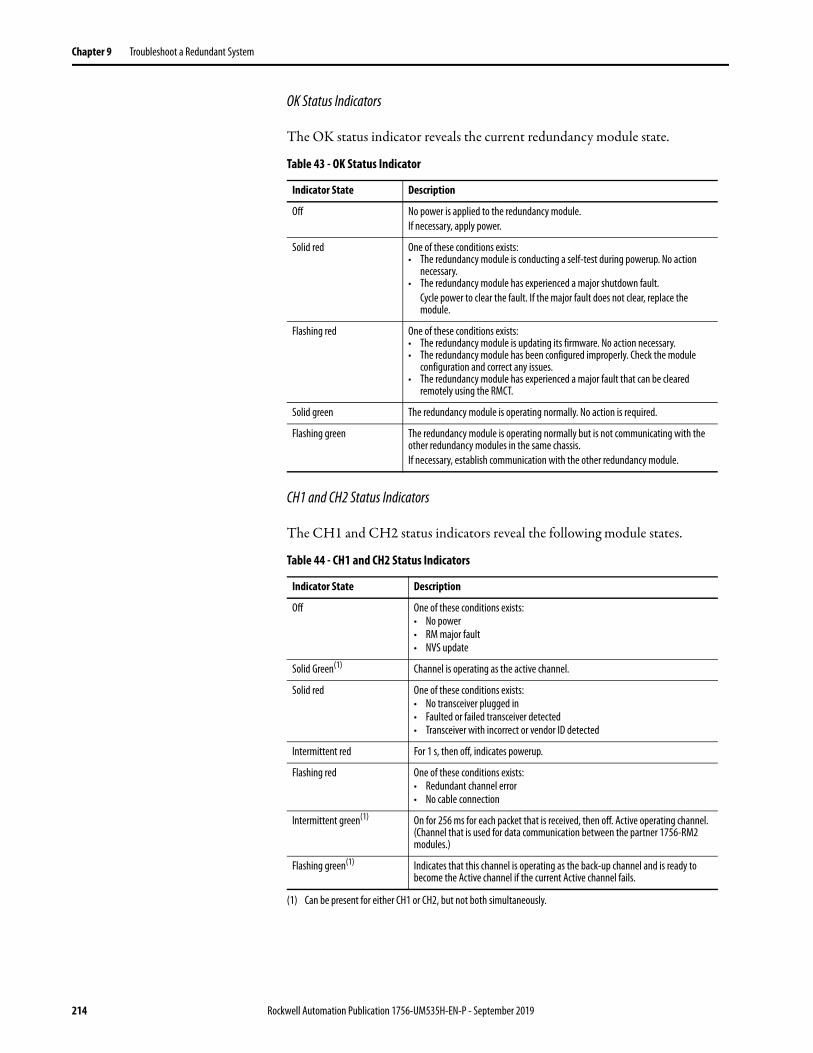
Chapter 9 Troubleshoot a Redundant System
OK Status Indicators
The OK status indicator reveals the current redundancy module state.
CH1 and CH2 Status Indicators
The CH1 and CH2 status indicators reveal the following module states.
Table 43 - OK Status Indicator
Indicator State Description
Off No power is applied to the redundancy module.If necessary, apply power.
Solid red One of these conditions exists:• The redundancy module is conducting a self-test during powerup. No action
necessary.• The redundancy module has experienced a major shutdown fault.
Cycle power to clear the fault. If the major fault does not clear, replace the module.
Flashing red One of these conditions exists:• The redundancy module is updating its firmware. No action necessary.• The redundancy module has been configured improperly. Check the module
configuration and correct any issues.• The redundancy module has experienced a major fault that can be cleared
remotely using the RMCT.
Solid green The redundancy module is operating normally. No action is required.
Flashing green The redundancy module is operating normally but is not communicating with the other redundancy modules in the same chassis.If necessary, establish communication with the other redundancy module.
Table 44 - CH1 and CH2 Status Indicators
Indicator State Description
Off One of these conditions exists:• No power• RM major fault• NVS update
Solid Green(1) Channel is operating as the active channel.
Solid red One of these conditions exists:• No transceiver plugged in• Faulted or failed transceiver detected• Transceiver with incorrect or vendor ID detected
Intermittent red For 1 s, then off, indicates powerup.
Flashing red One of these conditions exists:• Redundant channel error• No cable connection
Intermittent green(1)
(1) Can be present for either CH1 or CH2, but not both simultaneously.
On for 256 ms for each packet that is received, then off. Active operating channel. (Channel that is used for data communication between the partner 1756-RM2 modules.)
Flashing green(1) Indicates that this channel is operating as the back-up channel and is ready to become the Active channel if the current Active channel fails.
214 Rockwell Automation Publication 1756-UM535H-EN-P - September 2019

Troubleshoot a Redundant System Chapter 9
1756-RM/A and 1756-RM/B Status Indicators
Figure 60 - Redundancy Module Status Indicators for 1756-RM and 1756-RMXT Modules
Module Status Display
The module status display provides diagnostic information.
Table 45 - Module Status Display
Module Status Display Description
Four-character display executing self-test at powerup.No action necessary.
Txxx The redundancy module is executing a self-test at powerup. (xxx represents a hexadecimal test identification number.)Wait for self-test to finish. No action is required.
XFER Application firmware update is in progress.Wait for firmware update to finish. No action is required.
ERAS Boot mode - Erasing current redundancy module firmware.
PROG Boot mode - Updating redundancy module firmware.Wait for firmware update to finish. No action is required.
???? Resolving initial redundancy module state.Wait for state resolution to finish. No action is required.
PRIM Primary redundancy module.The module is operating as the primary module. No action is required.
DISQ Disqualified secondary redundancy module.Check the type and revision of the secondary partner module.
QFNG Qualifying secondary redundancy module.Redundant system status. No action is required.
SYNC Qualified secondary redundancy module.Redundant system status. No action is required.
LKNG Secondary redundancy module that is in process of locking for update.
LOCK Secondary redundancy module that is locked for update.
Exxx Major fault has occurred (xxx represents an error or fault code, with the two least-significant characters in decimal).Use the Error ID code to diagnose and address the error. For more information on error codes, see Redundancy Module Fault Codes and Display Messages on page 218.
EEPROM Update Required Onboard EEPROM is empty.Replace the module.
BOOT Erase Error Error in erasing NVS device while updating boot image.Cycle power to the module. If the error persists, replace the module.
BOOT Program Error Error in writing in NVS device while updating boot image.Cycle power to the module. If the error persists, replace the module.
PRI COM OKPRI COM OK
P R I M Module Status Display
Status Indicators
Rockwell Automation Publication 1756-UM535H-EN-P - September 2019 215

Chapter 9 Troubleshoot a Redundant System
APP Erase Error Error in erasing NVS device while updating application image.Cycle power to the redundancy module. If the error persists, replace the module.
APP Program Error Error in writing in NVS device while updating application image.Cycle power to the redundancy module. If the error persists, replace the module.
CONFIG Erase Error Error in erasing NVS device while updating configuration log image.Cycle power to the redundancy module. If the error persists, replace the module.
CONFIG Program Error Error in writing in NVS device while updating configuration log image.Cycle power to the redundancy module. If the error persists, replace the module.
EEPROM Write Error Error in writing in EEPROM device while updating configuration log image.Cycle power to the redundancy module. If the error persists, replace the module.
Application Update Required The module is running boot firmware. Download the application firmware that is obtained from the respective redundancy bundle.
ICPT A test line on the backplane is asserted. Check if the error message goes away after removing each module, one at a time. If error persists, cycle power to the chassis, or replace the chassis.
!Cpt All modules in the chassis do not belong to the same redundancy platform.
Table 45 - Module Status Display
Module Status Display Description
216 Rockwell Automation Publication 1756-UM535H-EN-P - September 2019

Troubleshoot a Redundant System Chapter 9
OK Status Indicators
The OK status indicator reveals the current redundancy module state.
Communication Status Indicator
The communication status indicator indicates activity on the redundancy module communication between chassis in the redundant chassis pair.
Chassis State Status Indicator
The Chassis State (PRI) status indicator identifies whether the chassis is primary. The PRI status indicator on the primary redundancy module remains solid green, and the PRI status indicator on the secondary redundancy module remains off.
Table 46 - OK Status Indicator
Indicator State Description
Off No power is applied to the redundancy module.If necessary, apply power.
Solid red One of these conditions exists:• The redundancy module is conducting a self-test during powerup.• No action necessary.• The redundancy module has experienced a major fault.
Cycle power to clear the fault. If the major fault does not clear, replace the module.
Flashing red One of these conditions exists:• The redundancy module is updating its firmware.• No action necessary.• The redundancy module has been configured improperly.• Check the module configuration and correct any issues.• The redundancy module has experienced a minor failure.
Cycle power to clear the fault. If the major fault does not clear, replace the module.
Solid green The redundancy module is operating normally. No action is required.
Flashing green The redundancy module is operating normally but is not communicating with the other redundancy module.If necessary, establish communication with the other redundancy module.
Table 47 - Communication Status Indicator
Indicator State Description
Off One of these conditions exist:• No power is applied to the module.• Apply power to the module.• There is no communication between redundancy modules in the redundant
chassis pair.Diagnose the redundancy configuration to determine why no communication is taking place.
Red < 1 second The module has been started and has established partner communication.No action is required.
Solid red The module has experienced a critical communication failure.Cycle power to clear the fault. If the major fault does not clear, replace the module.
Flashing green > 250 ms Communication activity is present.No action is required.
Rockwell Automation Publication 1756-UM535H-EN-P - September 2019 217
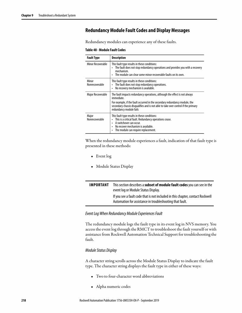
Chapter 9 Troubleshoot a Redundant System
Redundancy Module Fault Codes and Display Messages
Redundancy modules can experience any of these faults.
When the redundancy module experiences a fault, indication of that fault type is presented in these methods:
• Event log
• Module Status Display
Event Log When Redundancy Module Experiences Fault
The redundancy module logs the fault type in its event log in NVS memory. You access the event log through the RMCT to troubleshoot the fault yourself or with assistance from Rockwell Automation Technical Support for troubleshooting the fault.
Module Status Display
A character string scrolls across the Module Status Display to indicate the fault type. The character string displays the fault type in either of these ways:
• Two to four-character word abbreviations
• Alpha numeric codes
Table 48 - Module Fault Codes
Fault Type Description
Minor Recoverable This fault type results in these conditions:• The fault does not stop redundancy operations and provides you with a recovery
mechanism.• The module can clear some minor recoverable faults on its own.
Minor Nonrecoverable
This fault type results in these conditions:• The fault does not stop redundancy operations.• No recovery mechanism is available.
Major Recoverable The fault impacts redundancy operations, although the effect is not always immediate.For example, if the fault occurred in the secondary redundancy module, the secondary chassis disqualifies and is not able to take over control if the primary redundancy module fails
Major Nonrecoverable
This fault type results in these conditions:• This is a critical fault. Redundancy operations cease.• A switchover can occur.• No recover mechanism is available.• The module can require replacement.
IMPORTANT This section describes a subset of module fault codes you can see in the event log or Module Status Display.If you see a fault code that is not included in this chapter, contact Rockwell Automation for assistance in troubleshooting that fault.
218 Rockwell Automation Publication 1756-UM535H-EN-P - September 2019

Troubleshoot a Redundant System Chapter 9
This table describes the two to four-character word abbreviations.
The fault code is a four-character alphanumeric string. Valid characters are 0…9 and A through Z, except S and O. The first character is always E. Each firmware subsystem within the redundancy module is assigned a range of fault codes. Each subsystem assigns fault codes within its range.
If you encounter one of these error codes, record the Exxx code and contact Rockwell Automation Technical Support.
Recovery MessagesFor certain faults, the module status display provides recovery instructions. Up to four, four-character words are displayed.
Table 49 - Major Fault Code Messages
1st Word 2nd Word 3rd Word 4th Word Error Description
CFG LOG ERR Configuration log error. No action is required.
COMM RSRC ERR Communication resource error. Reset the redundancy module.
COMM RSRC ERR PRT1 Port1 Communication resource error on Backplane. Reset the redundancy module and check the chassis.
COMM RSRC ERR PRT2 Port2 Communication resource error on redundancy link. Complete these tasks:1. Reset the module.2. Check the cable.
COMM ERR PRT1 Port1 Communication error, Backplane communication. Check or replace the chassis.
COMM ERR PRT2 Port2 Communication error on the redundancy link. Check or replace the single-mode cable.
COMM ERR General Communication Error. No action is required.
DUPL RM Duplicate redundancy module. This module is not in control. Remove this redundancy module.
EVNT LOG ERR Event Log Error. No action is required.
FRMW ERR Firmware error. Update the firmware.
HDW ERR Hardware failure. Replace the module.
OS ERR Operating system error. Replace the module.
RM PWR DOWN The redundancy module Power Down, Module detected a DC_Fail condition.Check the other modules in the chassis.
WDOG ERR Watchdog time out. Reset the module.
WDOG FAIL Watchdog task failed its status check. Replace the module.
Table 50 - Recover Messages
Recovery Instruction Code Description
RPLC MOD Replace the module.
RSET MOD Reset the module.
REMV MOD Remove the module.
SEAT MOD Reinsert the module into the chassis.
Rockwell Automation Publication 1756-UM535H-EN-P - September 2019 219

Chapter 9 Troubleshoot a Redundant System
Notes:
220 Rockwell Automation Publication 1756-UM535H-EN-P - September 2019

Appendix A
Convert from a Non-redundant System
When converting from a non-redundant to a redundant system, first consider the following:
• You can use only Studio 5000 Logix Designer® versions 16, 19, 20, 24, 30, 31, or 32 in a redundancy system.
• The redundant chassis pair has controller, communication module and I/O module restrictions.
See Chapter 1, About ControlLogix Redundancy Systems for additional information.
Complete the tasks in this section to convert a non-redundant ControlLogix® system to a redundancy system.
Topic Page
Update the Configuration in Programming Software 222
Replace Local I/O Tags 224
Replace Aliases to Local I/O Tags 225
Remove Other Modules from the Controller Chassis 226
Add an Identical Chassis 227
Upgrade to Redundancy Firmware 227
Update the Controller Revision and Download the Project 227
Rockwell Automation Publication 1756-UM535H-EN-P - September 2019 221

Appendix A Convert from a Non-redundant System
Update the Configuration in Programming Software
These steps provide an overview of the process that is required to update the I/O Configuration tree in the programming software.
1. If you have I/O in the chassis with the controller, add a ControlLogix communication module to the appropriate network because I/O modules are not permitted in a redundant chassis.
You can now move the I/O modules to the new chassis in the I/O Configuration tree.
The I/O can be placed in this chassis.
222 Rockwell Automation Publication 1756-UM535H-EN-P - September 2019
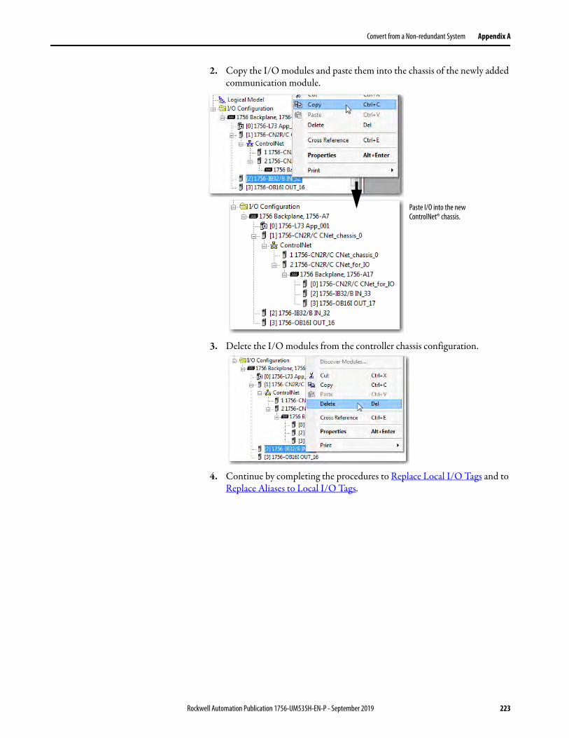
Convert from a Non-redundant System Appendix A
2. Copy the I/O modules and paste them into the chassis of the newly added communication module.
3. Delete the I/O modules from the controller chassis configuration.
4. Continue by completing the procedures to Replace Local I/O Tags and to Replace Aliases to Local I/O Tags.
Paste I/O into the new ControlNet® chassis.
Rockwell Automation Publication 1756-UM535H-EN-P - September 2019 223
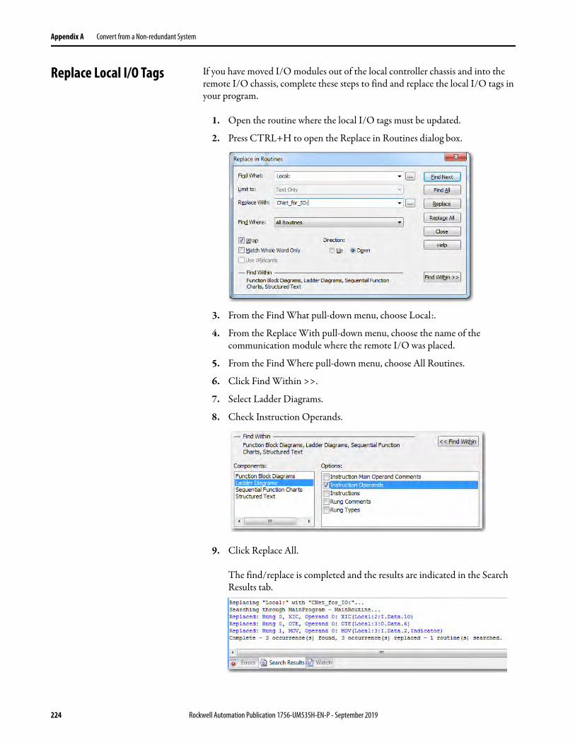
Appendix A Convert from a Non-redundant System
Replace Local I/O Tags If you have moved I/O modules out of the local controller chassis and into the remote I/O chassis, complete these steps to find and replace the local I/O tags in your program.
1. Open the routine where the local I/O tags must be updated.
2. Press CTRL+H to open the Replace in Routines dialog box.
3. From the Find What pull-down menu, choose Local:.
4. From the Replace With pull-down menu, choose the name of the communication module where the remote I/O was placed.
5. From the Find Where pull-down menu, choose All Routines.
6. Click Find Within >>.
7. Select Ladder Diagrams.
8. Check Instruction Operands.
9. Click Replace All.
The find/replace is completed and the results are indicated in the Search Results tab.
224 Rockwell Automation Publication 1756-UM535H-EN-P - September 2019

Convert from a Non-redundant System Appendix A
Replace Aliases to Local I/O Tags
If your program uses alias tags for the I/O modules that you are moving, complete these steps to replace alias tags.
1. In the programming software, open the Controller Tags.
2. Press CTRL+H to open the Replace Tags dialog box.
3. From the Find What pull-down menu, choose Local:.
4. From the Replace With pull-down menu, choose the name of the communication module where the remote I/O was placed.
5. From the Find Where pull-down menu, choose All Tags.
6. Click Find Within >>.
7. Select Alias and click Replace All.
The Search Results tab indicates the changed tags.
Rockwell Automation Publication 1756-UM535H-EN-P - September 2019 225
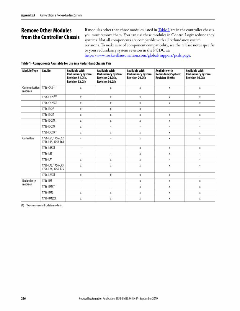
Appendix A Convert from a Non-redundant System
Remove Other Modules from the Controller Chassis
If modules other than those modules listed in Table 1 are in the controller chassis, you must remove them. You can use these modules in ControlLogix redundancy systems. Not all components are compatible with all redundancy system revisions. To make sure of component compatibility, see the release notes specific to your redundancy system revision in the PCDC at: http://www.rockwellautomation.com/global/support/pcdc.page.
Table 1 - Components Available for Use in a Redundant Chassis Pair
Module Type Cat. No. Available with Redundancy System: Revision 31.05x,Revision 32.05x
Available with Redundancy System: Revision 24.05x,Revision 30.05x
Available with Redundancy System: Revision 20.05x
Available with Redundancy System: Revision 19.05x
Available with Redundancy System: Revision 16.08x
Communication modules
1756-CN2(1) x x x x x
1756-CN2R(1) x x x x x
1756-CN2RXT x x x x x
1756-EN2F x x x - -
1756-EN2T x x x x x
1756-EN2TR x x x x -
1756-EN2TP x - - - -
1756-EN2TXT x x x x x
Controllers 1756-L61, 1756-L62, 1756-L63, 1756-L64
- - x x x
1756-L63XT - - x x x
1756-L65 - - x x -
1756-L71 x x x - -
1756-L72, 1756-L73, 1756-L74, 1756-L75
x x x x -
1756-L73XT x x x x -
Redundancy modules
1756-RM - - x x x
1756-RMXT - - x x x
1756-RM2 x x x x x
1756-RM2XT x x x x x
(1) You can use series B or later modules.
226 Rockwell Automation Publication 1756-UM535H-EN-P - September 2019
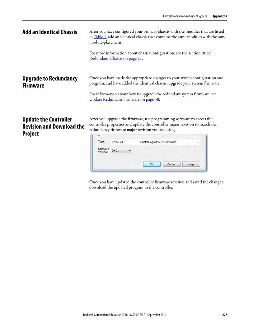
Convert from a Non-redundant System Appendix A
Add an Identical Chassis After you have configured your primary chassis with the modules that are listed in Table 1, add an identical chassis that contains the same modules with the same module-placement.
For more information about chassis configuration, see the section titled Redundant Chassis on page 21.
Upgrade to Redundancy Firmware
Once you have made the appropriate changes to your system configuration and program, and have added the identical chassis, upgrade your system firmware.
For information about how to upgrade the redundant system firmware, see Update Redundant Firmware on page 58.
Update the Controller Revision and Download the Project
After you upgrade the firmware, use programming software to access the controller properties and update the controller major revision to match the redundancy firmware major revision you are using.
Once you have updated the controller firmware revision and saved the changes, download the updated program to the controller.
Rockwell Automation Publication 1756-UM535H-EN-P - September 2019 227

Appendix A Convert from a Non-redundant System
Notes:
228 Rockwell Automation Publication 1756-UM535H-EN-P - September 2019

Appendix B
Redundancy Object Attributes
Table of Redundancy Object Attributes
Use this table of redundancy object attributes as a reference when programming to obtain the status of your redundancy system.
For this information Get this attribute Data Type
GSV/SSV Description
Redundancy status of the entire chassis.
ChassisRedundancyState INT GSV If Then
16#2 Primary with synchronized secondary
16#3 Primary with disqualified secondary
16#4 Primary with no secondary
16#10 Primary locked for update
Redundancy state of the partner chassis.
PartnerChassis RedundancyState
INT GSV If Then
16#8 Synchronized secondary
16#9 Disqualified secondary with primary
16#E No partner
16#12 Secondary locked for update
Redundancy status of the controller. ModuleRedundancy State INT GSV If Then
16#2 Primary with synchronized secondary
16#3 Primary with disqualified secondary
16#4 Primary with no secondary
16#6 Primary with synchronizing secondary
16#F Primary locking for update.
16#10 Primary locked for update
Redundancy state of the partner. PartnerModule RedundancyState
INT GSV If Then
16#7 Synchronizing secondary
16#8 Synchronized secondary
16#9 Disqualified secondary with primary
16#E No partner
16#11 Secondary locking for update
16#12 Secondary locked for update
Results of the compatibility checks with the partner controller.
CompatibilityResults INT GSV If Then
0 Undetermined
1 No compatible partner
2 Fully compatible partner
Rockwell Automation Publication 1756-UM535H-EN-P - September 2019 229
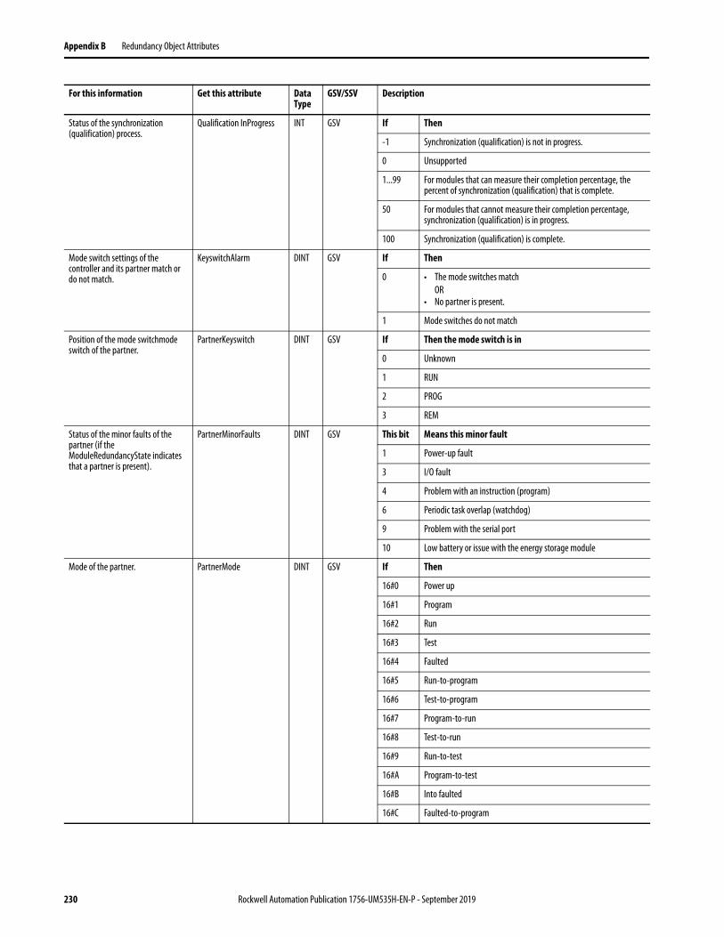
Appendix B Redundancy Object Attributes
Status of the synchronization (qualification) process.
Qualification InProgress INT GSV If Then
-1 Synchronization (qualification) is not in progress.
0 Unsupported
1...99 For modules that can measure their completion percentage, the percent of synchronization (qualification) that is complete.
50 For modules that cannot measure their completion percentage, synchronization (qualification) is in progress.
100 Synchronization (qualification) is complete.
Mode switch settings of the controller and its partner match or do not match.
KeyswitchAlarm DINT GSV If Then
0 • The mode switches matchOR
• No partner is present.
1 Mode switches do not match
Position of the mode switchmode switch of the partner.
PartnerKeyswitch DINT GSV If Then the mode switch is in
0 Unknown
1 RUN
2 PROG
3 REM
Status of the minor faults of the partner (if the ModuleRedundancyState indicates that a partner is present).
PartnerMinorFaults DINT GSV This bit Means this minor fault
1 Power-up fault
3 I/O fault
4 Problem with an instruction (program)
6 Periodic task overlap (watchdog)
9 Problem with the serial port
10 Low battery or issue with the energy storage module
Mode of the partner. PartnerMode DINT GSV If Then
16#0 Power up
16#1 Program
16#2 Run
16#3 Test
16#4 Faulted
16#5 Run-to-program
16#6 Test-to-program
16#7 Program-to-run
16#8 Test-to-run
16#9 Run-to-test
16#A Program-to-test
16#B Into faulted
16#C Faulted-to-program
For this information Get this attribute Data Type
GSV/SSV Description
230 Rockwell Automation Publication 1756-UM535H-EN-P - September 2019
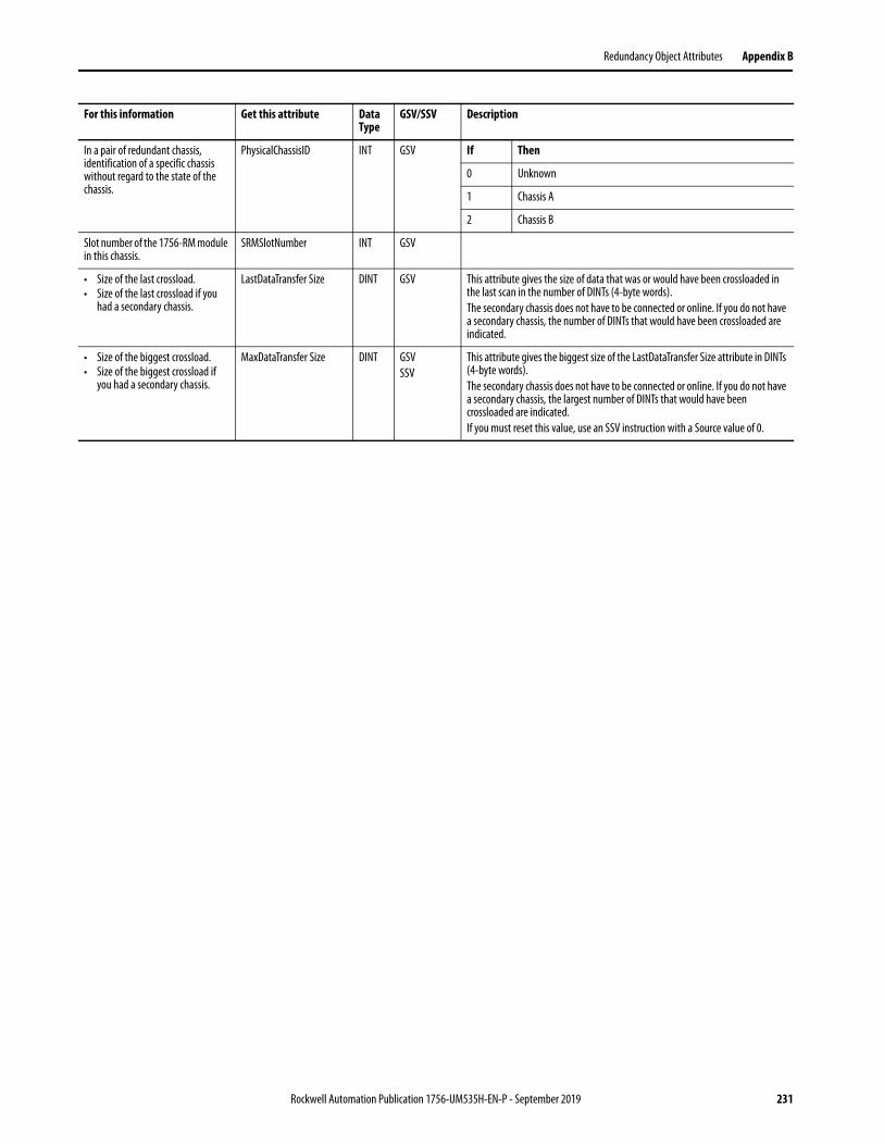
Redundancy Object Attributes Appendix B
In a pair of redundant chassis, identification of a specific chassis without regard to the state of the chassis.
PhysicalChassisID INT GSV If Then
0 Unknown
1 Chassis A
2 Chassis B
Slot number of the 1756-RM module in this chassis.
SRMSlotNumber INT GSV
• Size of the last crossload.• Size of the last crossload if you
had a secondary chassis.
LastDataTransfer Size DINT GSV This attribute gives the size of data that was or would have been crossloaded in the last scan in the number of DINTs (4-byte words).The secondary chassis does not have to be connected or online. If you do not have a secondary chassis, the number of DINTs that would have been crossloaded are indicated.
• Size of the biggest crossload.• Size of the biggest crossload if
you had a secondary chassis.
MaxDataTransfer Size DINT GSVSSV
This attribute gives the biggest size of the LastDataTransfer Size attribute in DINTs (4-byte words).The secondary chassis does not have to be connected or online. If you do not have a secondary chassis, the largest number of DINTs that would have been crossloaded are indicated.If you must reset this value, use an SSV instruction with a Source value of 0.
For this information Get this attribute Data Type
GSV/SSV Description
Rockwell Automation Publication 1756-UM535H-EN-P - September 2019 231

Appendix B Redundancy Object Attributes
Notes:
232 Rockwell Automation Publication 1756-UM535H-EN-P - September 2019
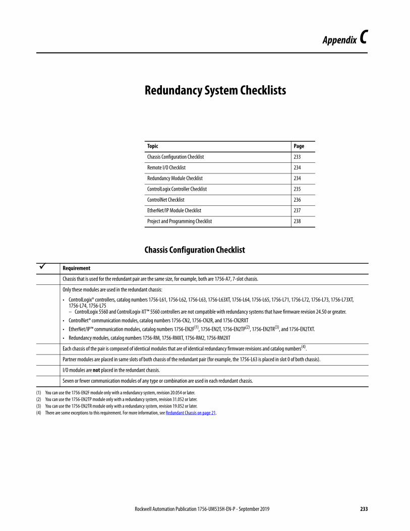
Appendix C
Redundancy System Checklists
Chassis Configuration Checklist
Topic Page
Chassis Configuration Checklist 233
Remote I/O Checklist 234
Redundancy Module Checklist 234
ControlLogix Controller Checklist 235
ControlNet Checklist 236
EtherNet/IP Module Checklist 237
Project and Programming Checklist 238
Requirement
Chassis that is used for the redundant pair are the same size, for example, both are 1756-A7, 7-slot chassis.
Only these modules are used in the redundant chassis:
• ControlLogix® controllers, catalog numbers 1756-L61, 1756-L62, 1756-L63, 1756-L63XT, 1756-L64, 1756-L65, 1756-L71, 1756-L72, 1756-L73, 1756-L73XT, 1756-L74, 1756-L75– ControlLogix 5560 and ControlLogix-XT™ 5560 controllers are not compatible with redundancy systems that have firmware revision 24.50 or greater.
• ControlNet® communication modules, catalog numbers 1756-CN2, 1756-CN2R, and 1756-CN2RXT• EtherNet/IP™ communication modules, catalog numbers 1756-EN2F(1), 1756-EN2T, 1756-EN2TP(2), 1756-EN2TR(3), and 1756-EN2TXT.• Redundancy modules, catalog numbers 1756-RM, 1756-RMXT, 1756-RM2, 1756-RM2XT
Each chassis of the pair is composed of identical modules that are of identical redundancy firmware revisions and catalog numbers(4).
Partner modules are placed in same slots of both chassis of the redundant pair (for example, the 1756-L63 is placed in slot 0 of both chassis).
I/O modules are not placed in the redundant chassis.
Seven or fewer communication modules of any type or combination are used in each redundant chassis.
(1) You can use the 1756-EN2F module only with a redundancy system, revision 20.054 or later.(2) You can use the 1756-EN2TP module only with a redundancy system, revision 31.052 or later.(3) You can use the 1756-EN2TR module only with a redundancy system, revision 19.052 or later.(4) There are some exceptions to this requirement. For more information, see Redundant Chassis on page 21.
Rockwell Automation Publication 1756-UM535H-EN-P - September 2019 233

Appendix C Redundancy System Checklists
Remote I/O Checklist
Redundancy Module Checklist
Requirement
I/O is not placed in redundant chassis.
I/O is connected to the redundant chassis by using one of these networking options:
• ControlNet connections to the same ControlNet network as the redundant controller chassis, without bridging.
• EtherNet/IP connections to the same EtherNet/IP network as the redundant controller chassis, without bridging. If in the I/O tree of the redundancy controller, all I/O and consumed tag connections must be multicast connections. The I/O tree of the redundancy controller can contain produced unicast tags that remote devices consume.
• A DeviceNet® network that is connected through a 1756-DNB DeviceNet communication module in a remote, that is, non-redundant, chassis.
• A universal remote I/O or Data Highway Plus™ network that is connected by using a 1756-DHRIO module in a remote (non-redundant) chassis.
Requirement
One redundancy module is placed in the same slot of each redundant chassis.
Series A and B redundancy modules are fully compatible. Therefore, you can use any combination of them in a partnered set, for example, a 1756-RM/A module in the primary chassis and a 1756-RM/B module in the secondary chassis. However, the best scan performance occurs when two Series B redundancy modules are used with ControlLogix 5570 controllers.
A fiber-optic cable connects the redundancy modules in the redundant chassis pair. The following are catalog numbers of fiber-optic cable you can order from Rockwell Automation:• 1756-RMC1 (1 m, 3.28 ft)• 1756-RMC3 (3 m, 9.84 ft)• 1756-RMC10 (10 m, 32.81 ft)If necessary, you can make your own fiber-optic cable that is up to 4 km (13,123.36 ft) for the 1756-RM/B module or 10 km (32,808.40 ft) for the 1756-RM2 module.
IMPORTANT The scan time is slightly extended when you downgrade a Series B redundancy module to a Series A module with a ControlLogix 5570 controller in the redundant chassis pair. In this case, raise the task watchdog limits by a factor of ~2x before downgrading. Thereafter, you can retune the limits that are based on the updated scan time numbers.
ControlLogix 5560 controllers that are used with a combination of Series A and Series B redundancy modules in the redundant chassis pair have the same performance a as if only Series A redundancy modules are used in the redundancy chassis pair. This result is regardless of the primary or secondary redundancy state.
234 Rockwell Automation Publication 1756-UM535H-EN-P - September 2019

Redundancy System Checklists Appendix C
ControlLogix Controller Checklist
Requirement
Identical ControlLogix controllers are placed in the same slot of both chassis of the redundant pair.
Partnered controllers are identical in redundancy firmware revision.
Within each redundant chassis, one or two (maximum) of these controllers(1) are used:
• 1756-L61, 1756-L62, 1756-L63, 1756-L63XT, 1756-L64(2), 1756-L65• 1756-L71, 1756-L72, 1756-L73, 1756-L73XT, 1756-L74, 1756-L75Do not combine ControlLogix 5560 and ControlLogix 5570 controllers in a redundant chassis.ControlLogix 5560 and ControlLogix-XT 5560 controllers are not compatible with redundancy systems that have firmware revision 24.052_kit1 or later.
Each controller in the redundancy chassis has enough memory to store twice the amount of controller data and I/O memory. See Knowledgebase ID 28972, accessible at: https://rockwellautomation.custhelp.com/A login is required to access the article.
Eight controller connections are reserved for redundancy use.
(1) The controllers can be of any series as long as the firmware revisions and catalog numbers are identical.(2) When using ControlLogix redundancy system, revision 16.081 or earlier, you cannot use two 1756-L64 controllers in the same chassis. You can, however, use a 1756-L64 controller in the same chassis
as a 1756-L61, 1756-L62, or 1756-L63 controller.
Rockwell Automation Publication 1756-UM535H-EN-P - September 2019 235

Appendix C Redundancy System Checklists
ControlNet Checklist
Requirement
ControlNet Module
Identical ControlNet modules are placed in the same slot of both chassis of the redundant pair.
ControlNet modules are identical in redundancy firmware revision and in catalog number.
Only the 1756-CN2, 1756-CN2R, or 1756-CN2RXT ControlNet modules are used.
Partnered ControlNet modules both have identical keeper information as explained in the ControlNet Network Configuration User Manual, publication CNET-UM001.
Three connections of the ControlNet module are appropriately reserved for redundancy system use.
ControlNet Network
USB ports of communication modules in the redundant chassis are not used while the system is running (online).
At least four ControlNet nodes are used on the ControlNet network. That is, at least two ControlNet nodes are on the ControlNet network along with the two ControlNet modules in the redundant chassis.
These requirements apply to at least one ControlNet node:
• It is not in the redundant chassis pair.• It uses a node address lower than the ControlNet node addresses of modules in redundant chassis pair.
ControlNet module partners in the redundant chassis have the following:
• Node address switches set to the same address (for example, the switches of both modules are set to node address 13).• Two consecutive node addresses reserved (for example, nodes 13 and 14) to accommodate a switchover. The primary ControlNet module can have an even or odd-
numbered node address.
The ControlNet network is scheduled by using techniques that are described in the ControlNet Network Configuration User Manual, publication CNET-UM001.(1)
Devices on other communication networks are bridged to the ControlNet network appropriately.
ControlNet HMI
A ControlNet network or a ControlNet-to-EtherNet/IP gateway is used to connect to HMI because your system requires that HMI be updated immediately after a switchover.
• PanelView™ Standard terminal, PanelView 1000e, or 1400e terminalFor an unscheduled network, ≤ 4 HMI terminals per controller are used.For a scheduled network, any number of terminals within the limits of the ControlNet network are used.
• PanelView Plus terminal, VersaView® industrial computer that runs a Windows CE operating systemRSLinx® Enterprise software, version 5.0 or later, is used.Within each controller and communication module, five connections for each PanelView Plus or VersaView terminal are reserved.
• FactoryTalk® View SE software with RSLinx communication software, version 2.52 or later, RSView®32 software, FactoryTalk Linx software, version 5.0The number of RSLinx servers that a controller uses is limited to 1…4 (maximum).
(1) Unscheduled ControlNet networks can be used, however, certain use considerations must be made. See Chapter 5, Configure the ControlNet Network on page 77.
236 Rockwell Automation Publication 1756-UM535H-EN-P - September 2019

Redundancy System Checklists Appendix C
EtherNet/IP Module Checklist
Requirement
EtherNet/IP Module
Identical EtherNet/IP communication modules are placed in the same slot of both chassis of the redundant chassis pair.
EtherNet/IP communication modules are one of these catalog numbers:
• 1756-EN2F(1), 1756-EN2T, 1756-EN2TP(2), 1756-EN2TR(3), and 1756-EN2TXT
EtherNet/IP Network
With firmware revision 19.052 and later, you can use an EtherNet/IP network for I/O and produced/consumed tags.With firmware revisions 16.081 and earlier, an EtherNet/IP network does not support I/O or produced/consumed tags.
Redundancy systems support unicast produced tags. Unicast consumed tags are not supported in redundancy systems.
USB ports of communication modules in the redundant chassis are not used while the system is running (online).
IP addresses of devices on the EtherNet/IP network are static and IP address swapping is enabled.(4)
EtherNet/IP HMI
HMI Blind Time is the time during a switchover from primary to secondary, when tag data from the controller is unavailable for reading or writing. See HMI Blind Time Reduction During a Switchover on page 17.IMPORTANT: This feature requires FactoryTalk Linx software, version 5.50.04 or later.
• PanelView Standard terminalNone (the use of the PanelView Standard terminal in a redundant system requires the same considerations as a non-redundant system).
• PanelView Plus terminal, VersaView industrial computer that runs a Windows CE operating systemFactoryTalk Linx software, version 3.0 or later, is used.Within each of the controllers and communication modules, five connections for each PanelView Plus or VersaView terminal are reserved.
• FactoryTalk View SE software with FactoryTalk Linx softwareFactoryTalk Linx software, version 3.0 or later is used.IP address swapping is used.HMI and both redundant chassis are on the same subnet.
• FactoryTalk View SE software with RSLinx software, version 2.x, RSView32 software, Any other HMI client software that uses RSLinx software, version 2.xThe number of RSLinx servers that a controller uses is limited to 1…4 (maximum).
(1) You can use the 1756-EN2F module only with a redundancy system, revision 20.054 or later.(2) You can use the 1756-EN2TP module only with a redundancy system, revision 31.052 or later.(3) You can use the 1756-EN2TR module only with a redundancy system, revision 19.052 or later.(4) Other IP address configurations are permitted, but require additional considerations. For more information, see IP Address Swapping on page 66.
Rockwell Automation Publication 1756-UM535H-EN-P - September 2019 237

Appendix C Redundancy System Checklists
Project and Programming Checklist
Also see the ControlLogix Controller Checklist on page 235.
Requirement
The Redundancy Module Date and Time has been set by using the RMCT (this in not required, but strongly recommended).
One project is created by using programming software and is downloaded to the primary controller.(1)
Redundancy is enabled within the Redundancy tab of the Controller Properties dialog box.
Time synchronization is not required for redundancy to function. If your application requires Time synchronization, then:• Enable Time synchronization on the Date/Time tab of the Controller Properties dialog box.• Select Time Sync and Motion on the Module Definition dialog box for the Ethernet module that is located in the local chassis.
Task configuration is either:
• One continuous task within the project.or• Multiple periodic tasks with only one task at the highest priority. Also, multiple tasks are structured at all different priorities and periods so that the fewest possible
separate tasks are used.
The redundant controller program does not contain:
• Event tasks.• Inhibited tasks.
Programming specific to critical I/O that must be bumpless is placed in the highest-priority user task according to your task configuration.
For ControlLogix 5560 controllers, the task watchdog is (2 * maximum_scan_time) + 150 ms when using ControlNet I/O and (2* maximum_scan_time) + 100 ms when using Ethernet I/O, where maximum_scan_time is the maximum scan time for the entire task to complete when the redundant controllers are synchronized. To calculate watchdog time for ControlLogix 5570 controllers, see Minimum Value for the Watchdog Time on page 148.
Scan time is minimized by using these techniques when possible:
• Unused tags are eliminated.• Arrays and user-defined data types are used instead of individual tags.• Redundancy data is synchronized at strategic points by using the Synchronize Data after Execution setting in the Program Properties dialog box.• Programming is written as compactly and efficiently as possible.• Programs are executed only when necessary.• Data is grouped according to frequency of use.• DINT tags are used instead of SINT or INT tags.
For produced/consumed data, the communication module in the remote chassis that holds the consuming controller uses the Comm Format: None.
Critical messages from a remote chassis to redundant chassis use cached connections.
Active tags on scan per controller are less than 10,000 tags/second.
(1) The project that is loaded on the primary controller is automatically crossloaded to the secondary controller when synchronization occurs.
If you use this task structure Then programming specific to bumpless I/O is in
One continuous task The continuous task.
One continuous task and one or more periodic tasks The highest-priority periodic task where only that one task is at the highest priority.
Multiple periodic tasks The highest-priority periodic task where only that one task is at the highest priority.
238 Rockwell Automation Publication 1756-UM535H-EN-P - September 2019
Index
Numerics1715 Redundant I/O systems 12, 14, 361756-CN2x modules 251756-EN2T
sockets 731756-EN2TR
sockets 731756-EN2Tx modules 251756-RM
status indicators 1741756-RM and 1756-RMXT modules 241756-RM2 46, 501756-RM2/A
ControlLogix 5570 123crossload 122dual fiber ports 57status indicators 174, 211
1756-RM2XT 46, 50status indicators 211
AArray (File)/Shift instructions 130Auto-Synchronization 98
BBOOTP/DHCP utility 74
Ccalculate
task watchdog 148CH1
status indicators 214CH2
status indicators 214chassis 44
designate 61ID 99install 45module placement 45primary 15secondary 15
chassis configuration list 233CIP Sync technology 12, 69 - 71clearing a fault 187communication
EtherNet/IP delay 28module connections 26modules 25
communication module 44unicast 18
componentsoverview 13
concise, program 128
configurationcontroller 112EtherNet/IP modules 74HMI 38remote I/O 36RMCT
determine if needed 90Configuration tab 97 - 99connections
communication 26controller 24
continuous taskexecution 117recommended 117
ControlFLASH 44, 59controller 22
configure redundancy 112connections 24enable user program 99event in Event Log 211save project 88status 175troubleshoot
non-redundant 210use multiple 123
controller logging 161ControlLogix 5560 235ControlLogix 5570 235
1756-RM2/A 123memory usage slider 159
ControlNetCPU usage 171keeper crossload 88keeper status 86module
check status 170monitor CPU usage 171network update time 79node requirements 30 - 32overview 30 - 33produce/consume connections 77redundant media 33remote I/O 14requirements 30 - 33sample programs 169, 171schedule
existing network 85new network 82
troubleshootkeeper status 203lost connection 206
unscheduled 81conversion
non-redundant to redundant 62convert
nonredundant to redundant 221 - 227CPU usage
Ethernet/IP 65
Rockwell Automation Publication 1756-UM535H-EN-P - September 2019 239
Index
crossload 461756-RM2/A 122ControlNet keepers 88default 117estimate 121redundancy object attributes 121redundant system 15scan time 121
DData Highway Plus 35date and time 99designate
primary chassis 61designation
chassis 61conduct 15qualification after 62
DeviceNet 35DSwNP
qualification status indicators 197DSwP
qualification status indicators 197dual fiber ports
1756-RM2/A 57duplex setting 74
Eelectrostatic discharge 47enable
user program control 99environmental considerations 43Ethernet
HMI blind time 17EtherNet/IP
1715 Redundant I/O systems 12configure module 74delay 28duplex setting 74IP address swapping 66 - 68overview 34produce/consume connections 72remote I/O 12, 14requested packet interval 65requirements 34set address 74troubleshoot
lost connection 206use of CIP Sync technology 69 - 71with HMI 38
Ethernet/IPCPU usage 65
Event Logcontroller event 211qualification events 63RMCT 194
Event Log tab 178 - 187clearing a fault 187export data for all events 185 - 186export single event data 182 - 184extended event information 181
executioncontinuous task 117periodic task 119
export data for a single event 182 - 184export data for all events 185 - 186export diagnostics button 200export event log 182 - 186extended event information 181
FFactoryTalk software 12fiber-optic cable 56
redundancy channels 54fiber-optic communication cable 44firmware 58
revision 41signed and unsigned 13update 58 - 61
firmware bundle 43flash upgrade 58
Hhardware
install 45HMI blind time
Ethernet 17Human-Machine-Interface (HMI) 38 - 40
use over ControlNet 39use over EtherNet/IP 38
II/O
1715 Redundant I/O systems 12, 36in redundancy system revisions 14multicast 234over EtherNet/IP network 12placement 14, 36
installhardware 44, 45power supply 45primary chassis 45 - 52redundancy module 46secondary chassis 52
installation instructions 51
240 Rockwell Automation Publication 1756-UM535H-EN-P - September 2019

Index
IP addressBOOTP/DHCP utility 74consecutive 66plan 74programming software 74RSLinx communication software 74set 74swap 66swapping 66 - 68switches 74
Kkeeper
crossloads 88status 86
mismatch 205module status display 203RSNetWorx for ControlNet software 203unconfigured 204valid 204
troubleshoot 203
Llaser radiation ports 50log
Recent Synchronization Attempts 101logic, scan-dependent 131
Mmemory usage slider
ControlLogix 5570 159mode switch
REM 59Module Info tab 94 - 96module placement
chassis 45module status display 166monitor
ControlNetsample programs 169, 171
motionunsupported feature 13
MSG instruction 144multicast
I/O 234
Nnetwork 81
ControlNetmonitor CPU usage 171overview 30 - 33
Data Highway Plus 35DeviceNet 34, 35EtherNet/IP 34
overview 28 - 29keeper 86keeper crossload 88Remote I/O 34schedule
existing 85new 82
Universal Remote I/O 35update time 79
network update time 79non-redundant controller 210non-redundant to redundant
conversion 62nonredundant, convert from 221 - 227
Oonline edits 152 - 159
finalize 156reserve memory 159retain edits 155test edits 154
operationschassis designation 15crossload 15qualification 15redundancy system 15switchover 15synchronization 15
optical ports 48
Pparallel redundancy protocol 76Partial Import Online 152periodic task 138
execution 119recommended 117
power supply 27, 44install 45
primary chassis 15designate 61designation 61 - 63installation 45 - 52
produce/consume connectionsover ControlNet 77over EtherNet/IP 72
produced tagsunicast 73
programcrossload
default 117
Rockwell Automation Publication 1756-UM535H-EN-P - September 2019 241

Index
scan time 121enable user control 99finalize test edits 156logic after switchover 141maintain data integrity 130 - 133manage tags 124messages for redundancy commands 142 -
146monitor system status 163online edits 152 - 159optimize task execution 134 - 139Partial Import Online 152periodic task 138reserve memory 159scan time
minimize 123 - 129synchronization
default 117system overhead time slice 135tags 124task type 117test edits 154use concise 128
programming software 74project
save 88PsDS
qualification status indicators 197PwNS
qualifcation status indicators 197PwQS
qualification status indicators 197
QQSwP
qualification status indicators 197qualification
after designation 62check in RMCT 168check status 166description of 15status via RMCT 63troubleshoot
non-redundant controller 210qualification status indicators 197
DSwNP 197DSwP 197PwDS 197PwNS 197PwQS 197QSwP 197
qualifyredundant module 63
quick startredundancy system 43
RRecent Synchronization Attempts log 101redundancy channels
fiber-optic cable 54
redundancy module 24, 44date and time 99info 94 - 96install 46lost connection between modules 208troubleshoot
missing 209Redundancy Module Configuration Tab
qualificationstatus 63
Redundancy Module Configuration Tool 89additional configuration 90check qualification 168Configuration tab 97 - 99Event Log tab 178 - 187identify version 92Module Info tab 94 - 96open 91Synchronization Status tab 103Synchronization tab 100 - 103System Update tab 104 - 109update 94
redundancy object attributesfor crossload time 121
redundancy systemchassis 21communication modules 25components 13controllers 22features 12operations 15power supply 27quick start 43redundancy modules 24restrictions 18using ControlNet 30 - 33using EtherNet/IP 28 - 29
redundant chassisdesignate 61example 19, 21
redundant fiber cable 53redundant fiber ports
single point of failure 12redundant media
ControlNet 33redundant module
qualify 63remove 64replace 64reset 63
REMmode switch 59
remote1715 Redundant I/O systems 36communication modules 35I/O 12
ControlNet 14EtherNet/IP 14placement 36
remote controllerunicast 72
removeredundant module 64
242 Rockwell Automation Publication 1756-UM535H-EN-P - September 2019

Index
replaceredundant module 64
requested packet intervalover EtherNet/IP 65
requirementsControlNet 30 - 33EtherNet/IP 34firmware 41
resetredundant module 63
restrictions 18redundancy system 18
RIUP 47RMCT 43, 89
Event Log 194troubleshoot 194version 92
RSLinx Classic 43RSLinx communication software 74
Sscan time
best performance 123concise programming 128crossload 121efficient crossloads 124 - 127minimize 123 - 129multiple controllers 123number of programs 124
scan-dependent logic 131schedule
ControlNet 82secondary chassis 15
designation 61 - 63intallation 52
set IP address 74SFP 213
small form pluggable 56transceiver 56
signed and unsignedfirmware 13
SIL3unsupported feature 13
single point of failureredundant fiber ports 12
small form pluggableSFP 56
sockets1756-EN2T 731756-EN2TR 73
softwareFactoryTalk Alarms and Events 41FactoryTalk Batch 41FactoryTalk View Site Edition 41optional 41programming software 74RSLinx communication software 74RSNetWorx for ControlNet 41RSNetWorx for EtherNet/IP 41RSView32 41
statusof qualification 63via module status display 166
status indicators1756-RM 1741756-RM2/A 174, 2111756-RM2XT 211CH1 214CH2 214use to troubleshoot 174
Studio 5000 Logix Designer 43use to troubleshoot 175
subnet 66switchover 15
description 16example 107locked attempts 109logic after 141monitor synchronization after 140test 168
synchronizationautomatic
synchronization 98default 117description of 15monitor after switchover 140
Synchronization Status tab 103Synchronization tab 100 - 103
attempts log 101commands in 101
systemqualification, system
synchronization 15system conversion 221system overhead time slice 136
optimize program 135System Update commands
abort system lock 106initiate locked switchover 107lock for update 105
System Update Lock Attempts 108System Update tab 104 - 109
commands 105 - 107Locked Switchover Attempts 109System Update Lock Attempts 108
Ttags
manage 124task 119
continuous, execution 117optimize execution 134 - 139periodic 138recommended 117
time and date 99transceiver
SFP 56troubleshoot 173 - 211
check status indicators 174controller event 211EtherNet/IP
Rockwell Automation Publication 1756-UM535H-EN-P - September 2019 243

Index
lost connection 206lost EtherNet/IP connection 206missing redundancy module 209qualification abort 210redundancy module
lost connection 208missing 209
RMCT 194synchronization
keeper status 203use
RSNetWorx for ControlNet software 203Studio 5000 Logix Designer 175
Uunicast
communication module 18produced tags 73remote controller 72
Universal Remote I/O 35unscheduled
ControlNet network 81unsupported feature
motion 13SIL3 13
updateRMCT 94system commands 105 - 107
upgradefirmware 58 - 61
user program control 99utilities
BOOTP/DHCP 74
Vversion
RMCT 92
Wwatchdog time 148, 238workstation software 43
244 Rockwell Automation Publication 1756-UM535H-EN-P - September 2019


Publication 1756-UM535H-EN-P - September 2019 Supersedes Publication 1756-UM535G-EN-P - August 2018 Copyright © 2019 Rockwell Automation, Inc. All rights reserved. Printed in the U.S.A.
Rockwell Automation Support
Use the following resources to access support information.
Documentation Feedback
Your comments will help us serve your documentation needs better. If you have any suggestions on how to improve this document, complete the How Are We Doing? form at http://literature.rockwellautomation.com/idc/groups/literature/documents/du/ra-du002_-en-e.pdf.
Technical Support Center Knowledgebase Articles, How-to Videos, FAQs, Chat, User Forums, and Product Notification Updates.
https://rockwellautomation.custhelp.com/
Local Technical Support Phone Numbers
Locate the phone number for your country. http://www.rockwellautomation.com/global/support/get-support-now.page
Direct Dial Codes Find the Direct Dial Code for your product. Use the code to route your call directly to a technical support engineer.
http://www.rockwellautomation.com/global/support/direct-dial.page
Literature Library Installation Instructions, Manuals, Brochures, and Technical Data.
http://www.rockwellautomation.com/global/literature-library/overview.page
Product Compatibility and Download Center (PCDC)
Get help determining how products interact, check features and capabilities, and find associated firmware.
http://www.rockwellautomation.com/global/support/pcdc.page
.
Rockwell Otomasyon Ticaret A.Ş., Kar Plaza İş Merkezi E Blok Kat:6 34752 İçerenköy, İstanbul, Tel: +90 (216) 5698400
Rockwell Automation maintains current product environmental information on its website at http://www.rockwellautomation.com/rockwellautomation/about-us/sustainability-ethics/product-environmental-compliance.page.
Allen-Bradley, ControlFLASH, ControlFLASH Plus, ControlLogix, ControlLogix-XT, Control Tower, Data Highway Plus, FactoryTalk, FLEX I/O, Integrated Architecture, Logix5000, PanelView, PhaseManager, PlantPAx, POINT I/O, PowerFlex,
Rockwell Automation, Rockwell Software, RSLinx, RSNetWorx, RSView, Stratix, Studio 5000 Automation & Engineering Design Environment, Studio 5000 Logix Designer, and VersaView are trademarks of Rockwell Automation, Inc.
CIP, CIP Sync, ControlNet, DeviceNet, and EtherNet/IP are trademarks of ODVA, Inc.
Trademarks not belonging to Rockwell Automation are property of their respective companies.