controllers dr, dp, fr and dfr - corporate webpage 92 060... · re 92060/04.2014, bosch rexroth ag...
TRANSCRIPT

RE 92060/04.2014, Bosch Rexroth AG
Features ▶ Control of pressure and flow ▶ Remote controlled optional ▶ Pressure controller for parallel operation optional ▶ Mechanical Vg min − and Vg max −limitation ▶ The special version enables mooring, swivel-through
operation, and decompression over the pump
Variable pump A4VSO, data sheet 92050
▶ For variable pump A4VSO series 1 and 3 ▶ Open circuit
ControllersDR, DP, FR and DFR
RE 92060Edition: 04.2014Replaces: 10.2006
ContentsOrdering code – A4VSO 2DR − pressure controller 3DRG − remote controlled pressure controller 6DP − pressure controller for parallel operation 11DPF − with flow controller 16FR/FR1 − flow controller 19FRG/FRG1 − flow controller with remote controlled pressure control 22DFR/DFR1 − pressure-flow controller 25General instructions 28

Bosch Rexroth AG, RE 92060/04.2014
2 DR, DP, FR and DFR | ControllersOrdering code – A4VSO
Ordering code – A4VSO
01 02 03 04 05 06 07 08 09 10 11 12 13
A4VS O / –
Hydraulic fluid01 For details see data sheet 92050
Axial piston unit02 Swashplate design, variable A4VS
Charge pump (impeller)03 without charge pump (no symbol) ● ● ● ● ● ● ● ● ●
with charge pump (impeller)only with port plate 25 (service line ports)
‒ ‒ ‒ ‒ ‒ ‒ ‒ ● ‒ L
Operating mode04 Pump, open circuit O
Size (NG)05 Geometric displacement 40 71 125 180 250 355 500 750 1000
Control device06 Pressure controller DR ● ● ● ● ● ● ● ● ● DR1)
remote controlled DR G ● ● ● ● ● ● ● ● ● DRG1)
Pressure control for parallel operation DP ● ● ● ● ● ● ● ● ● DP1)
with flow control DP F ‒ ‒ ● ● ● ● ‒ ‒ ‒ DPF
Flow controller FR ● ● ● ● ● ● ‒ ‒ ‒ FR
with pressure control, remote controlled FR G ● ● ● ● ● ● ‒ ‒ ‒ FRG
FR no connection from XF to the tank FR 1 ● ● ● ● ● ● ‒ ‒ ‒ FR1
FRG no connection from XF to the tank FRG 1 ● ● ● ● ● ● ‒ ‒ ‒ FRG1
Pressure and flow controller DFR ● ● ● ● ● ● ‒ ‒ ‒ DFR
no connection from XF to the tank DFR 1 ● ● ● ● ● ● ‒ ‒ ‒ DFR1
Series07 Series 1, index 0 ● ● ‒ ‒ ‒ ‒ ‒ ‒ ‒ 10
Series 3, index 0 ‒ ‒ ● ● ● ● ● ● ● 30
For details see data sheet 9205008 Direction of rotation
09 Seal
10 Drive shaft
11 Mounting flange 12 Service line ports
13 Through drive
● = Available ‒ = Not available
1) Available in mooring and swivel-through operation on request

RE 92060/04.2014, Bosch Rexroth AG
Controllers | DR, DP, FR and DFR DR − pressure controller
3
DR − pressure controller
The pressure controller limits the maximum pressure at the pump outlet within the control range of the variable pump. The variable pump only moves as much hydraulic fluid as is required by the consumers. If the operating pressure exceeds the pressure setting at the pressure control valve, the pump will regulate to a smaller displacement to reduce the control differential.
▶ Recommended setting range 50 to 350 bar. 350 bar is set as standard. When ordering, please state other values in plain text.
▶ Initial position in depressurized state: Vg max
▶ Mechanical minimum and maximum swivel angle limita-tion – The Vg min stop is set so that a pressure of 15 to
20 bar is set when port B is plugged. – The Vg max stop is set to nominal Vg max. When order-
ing, please state other settings values in plain text (possible setting ranges Vg max to 50 % Vg max).
The pressure controller for mooring and swivel-through operation is available on request. For decompression, the pump swivels over zero in operation as a motor.
Remote controlled pressure control optionally available – DRG see page 6, pressure controller for parallel operation DP see page 11
▼ Static characteristic
350
qv min qv max
50
Flow
Ope
ratin
g pr
essu
re p
[bar
]
≤ 3
bar
Pres
sure
dev
iatio
n
A4VSO - open circuit
▼ Flow direction S to B
Direction of rotation Pump
Swiveling range1) High pressure port
clockwise left B
counter-clockwise right B
1) cf. swivel angle indicator
15°
0° 1
5°
rightleft

Bosch Rexroth AG, RE 92060/04.2014
4 DR, DP, FR and DFR | ControllersOrdering code – A4VSO
Dynamic characteristicsLoad step by opening and closing a pressure line with a pressure-relief valve as load valve 1 m after the connection flange of the axial piston unit.
Swivel time t
Outward swivel time tSA Inward swivel time tSE
100
300
200
350
0
400
Vg max
Vg min
Dis
plac
emen
t (s
wiv
el a
ngle
)O
pera
ting
pres
sure
p [
bar]
NoteCharacteristics are measured median values at:
▶ n = 1500/1800 rpm ▶ Pressure safeguarding at 400 bar
Swivel times
NG tSA [s] against 20 bar
tSA [s] against 330 bar
tSE [s] zero stroke 350 bar
40 approx. 0.12 approx. 0.08 0.02
71 approx. 0.20 approx. 0.10 0.03
125 approx. 0.30 approx. 0.20 0.04
180 approx. 0.30 approx. 0.20 0.05
250 approx. 0.40 approx. 0.30 0.06
355 approx. 0.40 approx. 0.30 0.08
500 approx. 0.50 approx. 0.30 0.10
750 approx. 1.00 approx. 0.60 0.15
1000 approx. 1.50 approx. 0.90 0.20
The values of the outward swivel time tSA (Vg min → Vg max) can be shortened by the factor 2 to 3 if required (please contact us).This does not have any effect on the inward swivel time tSE .

RE 92060/04.2014, Bosch Rexroth AG
Controllers | DR, DP, FR and DFR Ordering code – A4VSO
5
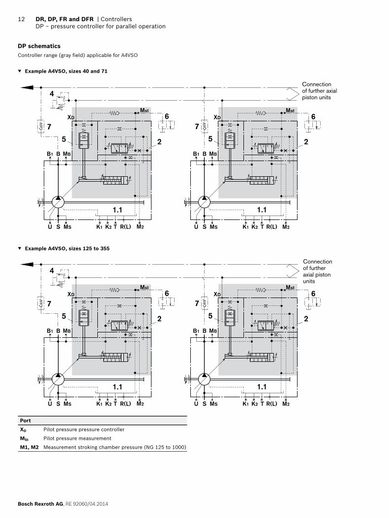
DR schematicsController range (gray field) applicable for A4VSO
▼ Example A4VSO, sizes 40 and 71
R(L)TU S MS K1 K2
MBB
1.1
B1
2
▼ Example A4VSO, sizes 500 to 1000
R(L)TU S MS K1 K2
MBB
1.1
B1 M1M2
2
3
Components
1 Pump with hydraulic control device
1.1 A4VSO (see data sheet 92050)
2 Pressure control valve
3 Intermediate plate (NG 125 to 1000)
▼ Example A4VSO, sizes 125 to 355
R(L)TU S MS K1 K2M1 M2
MBB
1.1
B1
2
3

Bosch Rexroth AG, RE 92060/04.2014
6 DR, DP, FR and DFR | ControllersDRG − remote controlled pressure controller
DRG − remote controlled pressure controller
Function and equipment as for DR.A pressure-relief valve (pos.4) can be piped externally at port XD for remote control, although the pressure-relief valve is not included in the scope of supply for the DRG control.Version with built-on valve on request.
The differential pressure at the pressure control valve (pos.2) is set to 20 bar as standard, the quantity of control liquid emerging at port XD is then approx. 1.5 l/min. If a different setting (recommended range 20 to 50 bar) is required, please state in plain text.
As a separate pressure-relief valve, we recommend: ▶ DBD 6 (hydraulic) as per data sheet 25402.
The maximum wire length should not exceed 2 m.
Note for setting the remote controlled pressure control:The setting value for the external pressure relief valve plus the differential pressure value at the pressure control valve determines the level of pressure control.Example: External pressure relief valve 330 bar Differential pressure at pressure control valve 20 bar Pressure control at 330 + 20 = 350 bar
Pres
sure
dev
iatio
n ≤
3 ba
r
max.350
qv min qv max
20O
pera
ting
pres
sure
p [b
ar]
Flow
External pressure-relief valve
Δp pressure control valve
For the function, description, and swivel times of the pres-sure controller DR, see pages 3 and 4.

RE 92060/04.2014, Bosch Rexroth AG
Controllers | DR, DP, FR and DFR DRG − remote controlled pressure controller
7
DRG schematicsController range (gray field) applicable for A4VSO
▼ Example A4VSO, sizes 40 and 71
R(L)TU S MS K1 K2
MBB
1.1
B1
2
XD4
▼ Example A4VSO, sizes 500 to 1000
R(L)TU S MS K1 K2
MBB
1.1
B1 3
2 XD
4
M2M1
Components
1 Pump with hydraulic control device
1.1 A4VSO (see data sheet 92050)
2 Pressure control valve
3 Intermediate plate (NG 125 to 1000)
4 External pressure-relief valve(not included in the scope of supply)
▼ Example A4VSO, sizes 125 to 355
R(L)TU S MS M1 M2K1 K2
MBB
1.1
B1 3
2
XD4

Bosch Rexroth AG, RE 92060/04.2014
8 DR, DP, FR and DFR | ControllersDRG − remote controlled pressure controller
Dimensions [mm]
Dimensions DR / DRG
▼ A4VSO, sizes 40 and 71
15
15
0 Einschraubloch M33
B
R(L)
B
XD
LR
XD
A8 A2
A1 A5
A7
A6
A3A4
NG1) A1 A2 A3 A4 A5 A6 A7 A8
40 260 140 147 137 47 67 209 128 For detailed dimensions and technical data of the variable pump, see data sheet 92050 (A4VSO)71 298 157 142 142 42 72 236 144
Port Standard Size2) pmax abs [bar]3) State4)
XD (DRG) Pilot pressure remote control pressure controller
DIN 3852 M14 x 1.5; 12 deep 400 O
XD (DR) X
1) For sizes 500 to 1000 see page 102) Observe the general instructions on page 28 for the maximum
tightening torques.3) Momentary pressure spikes may occur depending on the application.
Keep this in mind when selecting measuring devices and fittings.
4) O = Must be connected (plugged on delivery) X = Plugged (in normal operation)
Pressure control valve
Pressure control valve mounting for clockwise rotation
(Pressure control valve mounting for counter-clockwise rotation)
(XD for counter-clockwise rotation)

RE 92060/04.2014, Bosch Rexroth AG
Controllers | DR, DP, FR and DFR DRG − remote controlled pressure controller
9Dimensions [mm]
▼ A4VSO, sizes 125 to 355
15
15
0 Einschraubloch M33
B
XD
LR
R(L)
B
XD
M1(M2)
M2(M1)
A8
A2
A7
A1 A5
A6
(Pressure control valve mounting for counter-clockwise rotation)
(XD for counter-clockwise rotation)
Pressure control valve mounting for clockwise rotation
Intermediate plate
Pressure control valve
NG1) A1 A2 A5 A6 A7 A8
125/180 354 191 41 71 305 172 For detailed dimensions and technical data of the variable pump, see data sheet 92050 (A4VSO)250/355 424 238 41 71 367 208
Port Standard Size2) pmax abs [bar]3) State4)
XD (DRG) Pilot pressure remote control pressure controller
DIN 3852 M14 x 1.5; 12 deep 400O
XD (DR) X
M1; M2 Measurement of stroking chamber pressure
DIN 3852 M14 x 1.5; 12 deep (NG 125 and 180)M18 x 1.5; 12 deep (NG 250 and 355)
400 XX
1) For sizes 500 to 1000 see page 102) Observe the general instructions on page 28 for the maximum
tightening torques.3) Momentary pressure spikes may occur depending on the application.
Keep this in mind when selecting measuring devices and fittings.
4) O = Must be connected (plugged on delivery) X = Plugged (in normal operation)

Bosch Rexroth AG, RE 92060/04.2014
10 DR, DP, FR and DFR | ControllersDRG − remote controlled pressure controller
Dimensions [mm]
▼ A4VSO, sizes 500 to 1000
B
XD
R(L)
B
XD
M1(M2)
M2(M1)
A8
A2
A7
LRA1
A5
A6 15
15
0 Einschraubloch M33
Intermediate plate
Pressure control valve
(Pressure control valve mounting for counter-clockwise rotation)
Pressure control valve mounting for clockwise rotation
NG1) A1 A2 A5 A6 A7 A8
500 510 283 41 51 452 216 For detailed dimensions and technical data of the variable pump, see data sheet 92050 (A4VSO)750 582 322 41 51 484 235
1000 622 350 41 51 550 269
Port Standard Size2) pmax abs [bar]3) State4)
XD (DRG) Pilot pressure remote control pressure controller
DIN 3852 M14 x 1.5; 12 deep 400 O
XD (DR) X
M1; M2 Measurement of stroking chamber pressure
DIN 3852 M14 x 1.5; 12 deep 400 X
1) For sizes 40 and 71 see page 8; for sizes 125 to 355 see page 92) Observe the general instructions on page 28 for the maximum
tightening torques.
3) Momentary pressure spikes may occur depending on the application. Keep this in mind when selecting measuring devices and fittings.
4) O = Must be connected (plugged on delivery) X = Plugged (in normal operation)
(XD for counter-clockwise rotation)

RE 92060/04.2014, Bosch Rexroth AG
Controllers | DR, DP, FR and DFR DP − pressure controller for parallel operation
11
DP − pressure controller for parallel operation
Suitable for pressure control of multiple axial piston units A4VS in parallel operation.An external pressure-relief valve (pos. 4) actuates multiple axial piston units together over ports XD. The respective throttle valve (Pos. 5) provides the pressure increase pro-portional to the current pump setting that is required for parallel control.
▶ Initial position in depressurized state: Vg max
Differential pressure setting on the controllerThe control valve (pos. 2) plus throttle valve (pos. 5) is set to 33 bar when the XD port is relieved. The quantity of control liquid emerging at port XD is then approx. 1.5 l/min.The setting value for the external pressure relief valve plus the basic setting of the controller determines the level of pressure control.
▶ Adjustment range 33 to 350 bar
The pressure increase is retained independently of the setting value of the external pressure-relief valve and ensures the swivel angle deviation is low for all mutually activated pumps.Use the same as possible line lengths from ports XD to the pressure-relief valve.
The pressure-relief valve (Pos. 4) is not included in the scope of supply of the DP - please order separately.
▶ Recommendation: DBD 6 (hydraulic) as per data sheet 25402.
▶ Mechanical minimum and maximum swivel angle limita-tion
– The Vg min stop is set so that a pressure of 15 to 20 bar is set when port B is plugged.
– The Vg max stop is set to nominal Vg max. When ordering, please state other settings requests in plain text (pos-sible setting ranges Vg max to 50 % Vg max).
The maximum number of pumps is limited by the output of the used pressure-relief valve (pos. 4).Single pumps can be relieved to the amount of the basic setting by the relief valve (pos. 6) as required. A check valve (pos. 7) is then additionally needed at the pressure port. Both valves are not included in the scope of supply.Special version with mounted relief valve (pos. 6) is avail-able on request.
The DP controller for mooring and swivel-through operation is available on request. For decompression, the pump swivels over zero in operation as a motor.
Swivel times as for DR, see page 4.Flow control is optionally available – DPF see page 18
qv min qv max
0
100%
10%
Swiv
el a
ngle
aFlow
Swivel angle deviation ± 10 % from the setpoint value
▼ Static characteristic
qv min qv max
350
33
Flow
Ope
ratin
g pr
essu
re
p [b
ar]
Δp =
6.5
±2 b
ar
A4VSO - open circuit
▼ Flow direction S to B
Direction of rotation pump
Swiveling range1) High-pressure port
clockwise left B
counter-clockwise right B
1) cf. swivel angle indicator
15°
0° 1
5°
rightleft
Bosch Rexroth AG, RE 92060/04.2014
12 DR, DP, FR and DFR | ControllersDP − pressure controller for parallel operation
DP schematicsController range (gray field) applicable for A4VSO
▼ Example A4VSO, sizes 40 and 71
1.1
R(L)TU S MS K1 K2
BB1 MB
XD
2 25
76
5
76
4
1.1
R(L)TU S MS K1 K2
BB1
Mst
MB
XD
Mst
M2 M2
Connection of further axial piston units
▼ Example A4VSO, sizes 125 to 355
1.1
R(L)TU S MS K1 K2
BB1 MB
XD
2 25
76
5
76
4
1.1
R(L)TU S MS K1 K2
BB1
Mst
MB
XD
Mst
M2 M2
Connection of further axial piston units
Port
XD Pilot pressure pressure controller
MSt Pilot pressure measurement
M1, M2 Measurement stroking chamber pressure (NG 125 to 1000)

RE 92060/04.2014, Bosch Rexroth AG
Controllers | DR, DP, FR and DFR DP − pressure controller for parallel operation
13
▼ Example A4VSO, sizes 500 to 1000
R(L)TU S MS K1 K2
M2
R(L)TU S MS K1 K2
M1M2
Mst
BB1 MB MBBB1
2 2
3 3
5
7
6
5
7
6
4
XD XD
1.1 1.1
M1
Mst
Connection of further axial piston units
Port
XD Pilot pressure pressure controller
MSt Pilot pressure measurement
M1, M2 Measurement of stroking chamber pressure
Components
1 Pump with hydraulic control device
1.1 A4VSO (see data sheet 92050)
2 Control valve with pressure compensator
3 Intermediate plate (NG 500 to 1000)
4 Pressure-relief valve (not included in the scope of supply)
5 Throttle valve
6 Relief valve (not included in the scope of supply)
7 Check valve (not included in the scope of supply)
only required in combination with relief valve

Bosch Rexroth AG, RE 92060/04.2014
14 DR, DP, FR and DFR | ControllersDP − pressure controller for parallel operation
Dimensions [mm]
Dimensions DP
▼ A4VSO, sizes 40 and 71
M14x1.50
M14x1
.50
15
15
0 Einschraubloch M33
B
XD
A7 A2
A6
21.1
R(L)
XD
MSt
LRA1
A5
A3
B
A4
5
Schl.weite: 30 mm
(Control valve mounting for counter-clockwise rotation)
to flanging face
NG A1 A2 A3 A4 A5 A6 A7
40 260 210 147 137 39 133 170 For detailed dimensions and technical data of the variable pump, see data sheet 92050 (A4VSO)71 225 225 142 142 39 155 187
125/180 354 261 – – 39 192 221
250/355 424 306 – – 39 237 268
Port Standard Size2) pmax abs [bar]3) State4)
XD Pilot pressure pressure controller DIN 3852 M14 x 1.5; 12 deep 400 O
MSt Measurement of stroking chamber pressure
DIN 3853 S8 shape W 400 X
M1; M2 Measurement of stroking chamber pressure
DIN 3852 M14 x 1.5; 12 deep (NG 125 and 180)M18 x 1.5; 12 deep (NG 250 and 355)
400 XX
Components, see page 13
▼ A4VSO, sizes 125 to 355
M14x1.50
M14x1
.50
15
15
0 Einschraubloch M33
B
XD
A7 A2
A6
21.1
5
3
R(L)
XD
MSt
A1 A5
B
M1(M2)
M2(M1)
LR
(Control valve mounting for counter-clockwise rotation)
to flanging face
1) Observe the general instructions on page 28 for the maximum tightening torques.
2) Momentary pressure spikes may occur depending on the application. Keep this in mind when selecting measuring devices and fittings.
3) O = Must be connected (plugged on delivery) X = Plugged (in normal operation)
Control valve mounting for clockwise rotation
Control valve mounting for clockwise rotation

RE 92060/04.2014, Bosch Rexroth AG
Controllers | DR, DP, FR and DFR DP − pressure controller for parallel operation
15Dimensions [mm]
▼ A4VSO, sizes 500 to 1000
B
XD
A7 A2
A6
21.1
5
3
MSt
MSt
R(L)
XD
A1
A5
BM1(M2)
M2(M1)
LR
15
15
0 Einschraubloch M33
NG A1 A2 A5 A6 A7
500 510 353 39 268 313 For detailed dimensions and technical data of the variable pump, see data sheet 92050 (A4VSO)750 582 392 39 290 352
1000 622 419 39 349 379
Port Standard Size1) pmax abs [bar]3) State3)
XD Pilot pressure pressure controller DIN 3852 M14 x 1.5; 12 deep 400 O
MSt Pilot pressure measurement DIN 3853 S8 shape W 400 X
M1; M2 Measurement of stroking chamber pressure
DIN 3852 M14 x 1.5; 12 deep 400 X
Components
1 Pump with hydraulic control device
1.1 A4VSO (see data sheet 92050)
2 Control valve with pressure compensator
3 Intermediate plate (NG 125 to 1000)
5 Throttle valve
1) Observe the general instructions on page 28 for the maximum tightening torques.
2) Momentary pressure spikes may occur depending on the application. Keep this in mind when selecting measuring devices and fittings.
3) O = Must be connected (plugged on delivery) X = Plugged (in normal operation)
Control valve mounting for clockwise rotation
(Control valve mounting for counter-clockwise rotation)
to flanging face

Bosch Rexroth AG, RE 92060/04.2014
16 DR, DP, FR and DFR | ControllersDPF − with flow controller
DPF − with flow controller
In addition to the pressure control function, a differential pressure can be used to control the flow from the pumps, e. g. by an orifice between the pump and consumer. The pump supplies only the amount of fluid actually required by the consumer.The flow of the pump is then dependent on the cross sec-tion of the external measuring orifice (pos. 9), which is located between the pump and the consumer. The flow is nearly independent of the load pressure below the setting value of the pressure control and within the control range of the pump.For a description of the flow controller, see FR page 19.For the function and technical data of the parallel pressure controller DP, see page 11.
A4VSO - open circuit
▼ Static characteristic
qv min qv max
350
33
Flow
Ope
ratin
g pr
essu
re
p [b
ar]
Δp =
6.5
±2 b
ar
▼ Flow direction S to B
Direction of rotation pump
Swiveling range1) High-pressure port
clockwise left B
counter-clockwise right B
1) cf. swivel angle indicator
15°
0° 1
5°
rightleft

RE 92060/04.2014, Bosch Rexroth AG
Controllers | DR, DP, FR and DFR DPF − with flow controller
17
DPF schematics
▼ A4VSO, size 125 to 355
1.1
R(L)TU S MS K1 K2M1 M2
MBBB1
XD
XF
3
5
7
5
78
2
3
8
2
9
1.1
R(L)TU S MS K1 K2M1 M2
MBBB1
XD
XF 6
4
Mst
6Mst
Connection of further pumps
Port
XD Pilot pressure pressure controller
XF Pilot pressure flow controller
MSt Pilot pressure measurement
M1, M2
Measurement of stroking chamber pressure
Components
1 Pump with hydraulic control device
1.1 A4VSO (see data sheet 92050)
2 Control valve with pressure compensator
3 Intermediate plate
4 Pressure-relief valve (not included in the scope of supply)
5 Throttle valve
6 Relief valve (not included in the scope of supply)
7 Check valve (not included in the scope of supply)
only required in combination with relief valve
8 Flow control valve
9 External measuring orifice (not included in the scope of supply)

Bosch Rexroth AG, RE 92060/04.2014
18 DR, DP, FR and DFR | ControllersDPF − with flow controller
Dimensions [mm]
Dimensions DPF
▼ A4VSO, size 125 to 355
15
15
0 Einschraubloch M33
B
XD
A8
A2
A11
2
1.1
5 3
A9A7
A11
8XF
A1 A5
A6
XF
MSt
B
A12
XD
R(L)
M1(M2)
M2(M1)
LR
to flanging faceto flanging face
(Valve mounting for counter-clockwise rotation)
Valve mounting for clockwise rotation
to flanging face
NG A1 A2 A5 A6 A7 A8 A9 A10 A11 A12
125 354 261 41 71 191.5 172 345 220.5 371 39 For detailed dimensions and technical data of the variable pump, see data sheet 92050 (A4VSO)180 354 261 41 71 191.5 172 345 220.5 371 39
250 424 306 41 51 236.5 208 407 267.5 433 39
355 424 306 41 51 236.5 208 407 267.5 433 39
Port Standard Size 1) pmax abs [bar]2) State 3)
XD Pilot pressure pressure controller DIN 3852 M14 x 1.5; 12 deep 400 O
XF Pilot pressure flow controller DIN 3852 M14 x 1.5; 12 deep 400 O
MSt Pilot pressure measurement DIN 3853 S8 shape W 400 X
M1; M2 Measurement of stroking chamber pressure
DIN 3852 M14 x 1.5; 12 deep (NG 125 and 180)M18 x 1.5; 12 deep (NG 250 and 355)
400 XX
Components, see page 17
1) Observe the general instructions on page 28 for the maximum tightening torques.
2) Momentary pressure spikes may occur depending on the application. Keep this in mind when selecting measuring devices and fittings.
3) O = Must be connected (plugged on delivery) X = Plugged (in normal operation)

RE 92060/04.2014, Bosch Rexroth AG
Controllers | DR, DP, FR and DFR FR/FR1 − flow controller
19
FR/FR1 − flow controller
The flow controller adjusts the displacement of the pump to the volume required by the consumer.The flow of the pump is then dependent on the cross sec-tion of the external measuring orifice (pos. 4), which is located between the pump and the consumer. The flow is nearly independent of the load pressure within the control range of the pump (see maximum flow deviation below).The opening cross section of the measuring orifice deter-mines the flow of the pump.The flow controller compares the pressure before the measuring orifice with that after the orifice and maintains the pressure drop encountered here (differential pressure ∆p) and thus controls the flow.If the differential pressure ∆p increases, the pump is swiv-eled back (towards Vg min), if the differential pressure ∆p decreases the pump is swiveled out (towards Vg max), until equilibrium in the valve is restored.∆porifice = ppump – pconsumer
The standard setting on the flow control valve (pos. 2) for ∆p is 14 bar. If a different setting (recommended range 14 to 25 bar) is required, please state in plain text. Higher values on request.The stand-by pressure in zero stroke operation (sensing orifice plugged) is slightly above the ∆p setting.The DFR1 version has no connection from XF to the tank.
▶ Initial position in depressurized state: Vg max
▶ Mechanical minimum and maximum swivel angle limita-tion – The Vg min stop is set so that a pressure of 15 to
20 bar is set when port B is plugged. – The Vg max stop is set to nominal Vg max. When ordering,
please state other settings requests in plain text (possible setting ranges Vg max to 50 % Vg max).
A4VSO - open circuit
▼ Static characteristic
Flow
350
014
qv min qv max
min
max
Ope
ratin
g pr
essu
re p
→
▼ Flow direction S to B
Direction of rotation pump
Swiveling range1) High-pressure port
clockwise left B
counter-clockwise right B
1) cf. swivel angle indicator
▼ Static characteristic at variable rotational speed
Flow
qv
Rotational speed n
▼ Max. flow deviation
measured at drive speed n = 1500 rpm
Size 40 71 125 180 250 355
∆pv [l/min] 3 3 5 6 8 10
15°
0° 1
5°
rightleft

Bosch Rexroth AG, RE 92060/04.2014
20 DR, DP, FR and DFR | ControllersFR/FR1 − flow controller
▼ Dynamic characteristic
The characteristics are measured median values.Flow step standby / qv max through relief of the X port to the tank.
25
75
50
0
100
100
300
200
350
50
400
Dis
plac
emen
t V
g [%
]
Load
pre
ssur
e [b
ar]
Standby
Outward swivel time tSA Inward swivel time tSE
Swivel time t
Swivel times
NG tSA [s] standby...350 bar
tSE [s] 350 bar...standby
tSE [s] 50 bar...standby
40 approx. 0.1 0.02 0.050
71 approx. 0.2 0.03 0.075
125 approx. 0.3 0.04 0.100
180 approx. 0.4 0.05 0.120
250 approx. 0.4 0.06 0.150
355 approx. 0.5 0.07 0.180
The values of the outward swivel time tSA (Vg min → Vg max) can be shortened by the factor 2 to 3 if required (please contact us).This does not have any effect on the inward swivel time tSE .
FR/FR1 schematics
▼ A4VSO, sizes 40 and 71
1.1
R(L)TU S MS K1 K2
BB1 MB
XF
2
4
B
for FR1 plugged
Port
XF Pilot pressure flow controller
M1, M2 Measurement stroking chamber pressure (NG 125 to 355)
Components
1 Pump with hydraulic control device
1.1 A4VSO (see data sheet 92050)
2 Flow control valve
3 Intermediate plate (NG 125 to 355)
4 External measuring orifice (not included in the scope of supply)
▼ A4VSO, sizes 125 to 355
1.1
R(L)TU S MS K1M1 M2
BB1 MB
XF
B
3
24
K2
for FR1 plugged

RE 92060/04.2014, Bosch Rexroth AG
Controllers | DR, DP, FR and DFR FR/FR1 − flow controller
21Dimensions [mm]
Dimensions FR/FR1
▼ A4VSO, sizes 40 and 71
M14x1.50
M14x1
.50
15
15
0 Einschraubloch M33
BA8
A1
21.1
A7
XF
A2
A5
A6
XF
B
R(L)
LR
A3
A4
Schl.weite: 30 mm
(Valve mounting for counter-clock-wise rotation)
to flanging face
NG A1 A2 A3 A4 A5 A6 A7 A8
40 260 140 147 137 47 67 209 128 For detailed dimensions and technical data of the variable pump, see data sheet 92050 (A4VSO)71 298 157 142 142 42 72 236 144
125/180 354 191 – – 41 71 305 172
250/355 424 238 – – 41 71 367 208
Port Standard Size1) pmax abs [bar]2) State3)
XF Pilot pressure flow controller DIN 3852 M14 x 1.5; 12 deep 400 O
M1; M2 Measurement of stroking chamber pressure
DIN 3852 M14 x 1.5; 12 deep (NG 125 and 180)M18 x 1.5; 12 deep (NG 250 and 355)
400 XX
▼ A4VSO, size 125 to 355
M14x1.50
M14x1
.50
15
15
0 Einschraubloch M33
B
21.1
XF3
A8
A7
A2
A1 A5
A6
XF
B
R(L)
LR
M1(M2)
M2(M1)
(Valve mounting for coun-ter-clockwise rotation)
to flanging face
1) Observe the general instructions on page 28 for the maximum tightening torques.
2) Momentary pressure spikes may occur depending on the application. Keep this in mind when selecting measuring devices and fittings.
3) O = Must be connected (plugged on delivery) X = Plugged (in normal operation)
Valve mounting for clockwise rotation
Valve mounting for clockwise rotation
(XF for counter-clockwise rotation) (XF for counter-
clockwise rotation)

Bosch Rexroth AG, RE 92060/04.2014
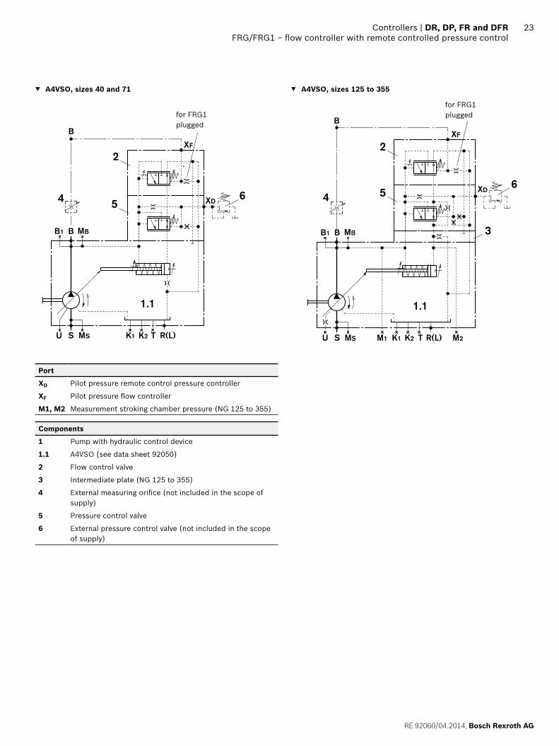
22 DR, DP, FR and DFR | ControllersFRG/FRG1 − flow controller with remote controlled pressure control
FRG/FRG1 − flow controller with remote controlled pressure control
The FRG pressure flow controller is a combination of FR (FR1) and DRG. The flow control is overridden by a pressure control that is controlled by a separate pressure-relief valve (pos. 4).For the function and technical data of the remote con-trolled pressure control, see page 7.For the function and technical data of the FR flow control-ler, see pages 19 and 20.The FRG1 version has no connection from XF to the tank.
A4VSO - open circuit
▼ Characteristic
Flow
350
020
qv min qv max
min
max
Ope
ratin
g pr
essu
re p
[ba
r]
▼ Flow direction S to B
Direction of rotation Pump
Swiveling range1) High-pressure port
clockwise left B
counter-clockwise right B
1) cf. swivel angle indicator
15°
0° 1
5°
rightleft
RE 92060/04.2014, Bosch Rexroth AG
Controllers | DR, DP, FR and DFR FRG/FRG1 − flow controller with remote controlled pressure control
23
▼ A4VSO, sizes 40 and 71
1.1
R(L)TU S MS K1 K2
BB1 MB
XF
XD5
2
64
B
for FRG1 plugged
Port
XD Pilot pressure remote control pressure controller
XF Pilot pressure flow controller
M1, M2 Measurement stroking chamber pressure (NG 125 to 355)
Components
1 Pump with hydraulic control device
1.1 A4VSO (see data sheet 92050)
2 Flow control valve
3 Intermediate plate (NG 125 to 355)
4 External measuring orifice (not included in the scope of supply)
5 Pressure control valve
6 External pressure control valve (not included in the scope of supply)
▼ A4VSO, sizes 125 to 355
1.1
R(L)TU S MS K1 K2M1 M2
BB1 MB
B
XF
XD
3
5
2
64
for FRG1 plugged

Bosch Rexroth AG, RE 92060/04.2014
24 DR, DP, FR and DFR | ControllersFRG/FRG1 − flow controller with remote controlled pressure control
Dimensions [mm]
Dimensions FRG/FRG1
▼ A4VSO, sizes 40 and 71
15
15
0 Einschraubloch M33
B
A8
A2
A10
2
1.1
5
A9A7
XFXD
XF
XD
B
A1 A5
R(L)
LR
A4
A3
A6
Schl.weite: 30 mm Schl.weite: 30 mm
to flanging faceto flanging face
Valve mounting for clockwise rotation
(Valve mounting for counter-clockwise rotation)
to flanging face
▼ A4VSO, size 125 to 355
15
15
0 Einschraubloch M33
B
A8
A2
A10
2
1.1
5
A9A7
XFXD3
A1 A5
A6
XD
B
R(L)
M1(M2)
M2(M1)
LR
XF
to flanging faceto flanging face
Valve mounting for clockwise rotation
(Valve mounting for counter-clockwise rotation)
to flanging face
NG A1 A2 A3 A4 A5 A6 A7 A8 A9 A10
40 260 140 147 137 47 67 209 128 249 275 For detailed dimensions and technical data of the variable pump, see data sheet 92050 (A4VSO)
71 298 157 142 142 42 72 236 144 276 302
125/180 354 191 – – 41 71 305 172 345 371
250/355 424 238 – – 41 71 367 208 407 433
Port Standard Size1) pmax abs [bar]2) State3)
XD Pilot pressure remote control pressure controller
DIN 3852 M14 x 1.5; 12 deep 400 O
XF Pilot pressure flow controller DIN 3852 M14 x 1.5; 12 deep 400 O
M1; M2 Measurement of stroking chamber pressure
DIN 3852 M14 x 1.5; 12 deep (NG 125 and 180)M18 x 1.5; 12 deep (NG 250 and 355)
400 XX
Components, see page 23
1) Observe the general instructions on page 28 for the maximum tightening torques.
2) Momentary pressure spikes may occur depending on the application. Keep this in mind when selecting measuring devices and fittings.
3) O = Must be connected (plugged on delivery) X = Plugged (in normal operation)
(XD and XF for counter-clock-wise rotation)(XD and XF for counter-
clockwise rotation)

RE 92060/04.2014, Bosch Rexroth AG
Controllers | DR, DP, FR and DFR DFR/DFR1 − pressure-flow controller
25
DFR/DFR1 − pressure-flow controller
The DFR pressure and flow controller DFR is a combination of the DR pressure controller and FR flow controller. For the function and technical data, see DR (page 3) and FR (page 19). The DFR1 version has no connection from XF to the tank.
▶ Initial position in depressurized state: Vg max
▶ Mechanical minimum and maximum swivel angle limita-tion – The Vg min stop is set so that a pressure of 15 to
20 bar is set when port B is plugged. – The Vg max stop is set to nominal Vg max. When ordering,
please state other settings requests in plain text (possible setting ranges Vg max to 50 % Vg max).
A4VSO - open circuit
▼ Static characteristic
350
qv min qv max
50
Ope
ratin
g pr
essu
re p
[ba
r]Flow
Pre
ssur
e de
viat
ion
≤ 3
bar
▼ Flow direction S to B
Direction of rotation pump
Swiveling range1) High-pressure port
clockwise left B
counter-clockwise right B
1) cf. swivel angle indicator
15°
0° 1
5°
rightleft

Bosch Rexroth AG, RE 92060/04.2014
26 DR, DP, FR and DFR | ControllersDFR/DFR1 − pressure-flow controller
DFR/DFR1 schematics
▼ A4VSO, sizes 40 and 71
1.1
R(L)TU S MS K1 K2
BB1 MB
XF
B
5
2
4
for DFR1 plugged
Port
XF Pilot pressure flow controller
M1, M2 Measurement stroking chamber pressure (NG 125 to 355)
Components
1 Pump with hydraulic control device
1.1 A4VSO (see data sheet 92050)
2 Flow control valve
3 Intermediate plate (NG 125 to 355)
4 External measuring orifice (not included in the scope of supply)
5 Pressure control valve
▼ A4VSO, sizes 125 to 355
1.1
R(L)TU S MS K1 K2M1 M2
BB1 MB
XF
B
5
3
2
4
for DFR1 plugged

RE 92060/04.2014, Bosch Rexroth AG
Controllers | DR, DP, FR and DFR DFR/DFR1 − pressure-flow controller
27Dimensions [mm]
Dimensions DFR/DFR1
▼ A4VSO, sizes 40 and 7115
15
0 Einschraubloch M33
BA8
A2
2
1.1
5
A9A7
XF
XF
B
A1 A5
R(L) A4
A3
A6
LR
Schl.weite: 30 mm Schl.weite: 30 mm
to flanging face
Valve mounting for clockwise rotation
(Valve mounting for counter-clockwise rotation)
to flanging face
▼ A4VSO, size 125 to 355
15
15
0 Einschraubloch M33
B
A8 A2
2
1.1
A9A7
XF3 5
A1 A5
A6
B
R(L)
M1(M2)
M2(M1)
LR
XF
to flanging face
Valve mounting for clockwise rotation
(Valve mounting for counter-clockwise rotation)
to flanging face
NG A1 A2 A3 A4 A5 A6 A7 A8 A9
40 260 140 147 137 47 67 249 128 275 For detailed dimensions and technical data of the variable pump, see data sheet 92050 (A4VSO)71 298 157 142 142 42 72 276 144 302
125/180 354 191 – – 41 71 345 172 371
250/355 424 238 – – 41 71 407 208 433
Port Standard Size1) pmax abs [bar]2) State3)
XF Pilot pressure flow controller DIN 3852 M14 x 1.5; 12 deep 400 O
M1; M2 Measurement of stroking chamber pressure
DIN 3852 M14 x 1.5; 12 deep (NG 125 and 180)M18 x 1.5; 12 deep (NG 250 and 355)
400 XX
1) Observe the general instructions on page 28 for the maximum tightening torques.
2) Momentary pressure spikes may occur depending on the application. Keep this in mind when selecting measuring devices and fittings.
3) O = Must be connected (plugged on delivery) X = Plugged (in normal operation)

28
Bosch Rexroth AG, RE 92060/04.2014
Bosch Rexroth AGMobile ApplicationsAn den Kelterwiesen 1472160 Horb a.N., GermanyTel. +49 7451 [email protected]/brm
© This document, as well as the data, specifications and other information set forth in it, are the exclusive property of Bosch Rexroth AG. It may not be reproduced or given to third parties without its consent. The data specified above only serve to describe the product. No statements concerning a certain condition or suitability for a certain application can be derived from our information. The information given does not release the user from the obligation of own judgment and verification. It must be remembered that our products are subject to a natural process of wear and aging.
DR, DP, FR and DFR | ControllersGeneral instructions
General instructions
▶ Basically, the installation instructions for the variable pump A4VSO - data sheet 92050 apply.
▶ The DR, DP, FR, and DFR controllers together with the pump A4VSO are intended for open circuit operation.
▶ The project planning, installation and commissioning of the axial piston unit requires the involvement of skilled person.
▶ Before using the axial piston unit, please read the corre-sponding instruction manual completely and thoroughly. If necessary, these can be requested from Bosch Rexroth.
▶ Depending on the operating conditions of the axial piston unit (operating pressure, fluid temperature), the characteristic may shift.
▶ Service line ports: – The ports and fastening threads are designed for the
specified maximum pressure. The machine or system manufacturer must ensure that the connecting ele-ments and lines correspond to the specified applica-tion conditions (pressure, flow, hydraulic fluid, tem-perature) with the necessary safety factors.
– The service line ports and function ports can only be used to accommodate hydraulic lines.
▶ The data and notes contained herein must be adhered to. ▶ Before finalizing your design, request a binding installa-
tion drawing. ▶ Not all variants of the product are approved for use in
safety functions according to ISO 13849. Please consult the responsible contact person at Bosch Rexroth if you require reliability parameters (e.g. MTTFd) for functional safety.
▶ Pressure controls are not backups against pressure over-load. A separate pressure-relief valve is to be provided in the hydraulic system.
▶ The following tightening torques apply: – Fittings:
Observe the manufacturer's specifications regarding the tightening torques of the fittings used.
– Mounting bolts: For mounting bolts with metric ISO thread according to DIN 13 or thread according to ASME B1.1, we recommend checking the tightening torque in indi-vidual cases in accordance with VDI 2230.
– Female threads in the axial piston unit: The maximum permissible tightening torques MG max are maximum values for the threaded holes and must not be exceeded. For values, see the following table.
– Threaded plugs: For the metallic threaded plugs supplied with the axial piston unit, the required tightening torques of threaded plugs MV apply. For values, see the follow-ing table.
Ports Maximum permissible tightening torque of the female threads MG max
Required tightening torque of the threaded plugs MV
WAF Hexagon socket for the threaded plugs
Standard Thread size
DIN 3852-1 M14 x 1,5 80 Nm 35 Nm 6 mm
M18 x 1,5 140 Nm 60 Nm 8 mm
DIN 3853 S8 shape W 50 Nm 40 Nm 19 mm external hexagon of the fitting