controller t esm-4420 48 x 48 din 1/16 temperature ...4420 esm-4420 48 x 48 din 1/16 temperature...
TRANSCRIPT

ES
M-
48x48
DIN
1/1
6Tem
pera
ture
Co
ntr
oller
4420
ESM-4420 48 x 48 DIN 1/16Temperature Controller with Universal Input
- 4 digits process(PV) and 4 digits process set value- Universal process input (TC, RTD )
- Adaptation of PID Coefficients to the system with Self-Tuneoperation (Step Response Tuning)- Programmable Heating or Cooling Functions for Control Output- Alarm Functions for Alarm Output
(SV) display
- Configurable ON/OFF, P, PI, PD and PID control forms
Instruction Manual. ENG ESM-4420 02 V03 04/08
2
Instruction manual of ESM-4420 Temperature Controller consists of two main sections.Explanation of these sections are below. Also, there are other sections which include orderinformation and technical specifications of the device. All titles and page numbers in instructionmanual are in “ ” section. User can reach to any title with section number.
In this section, physical dimensions of the device, panel mounting, electrical wiring,physical and electrical installation of the device to the system are explained.
Also in these sections, there are warnings to prevent serious injury while doing thephysical and electrical mounting or using the device.
Explanation of the symbols which are used in these sections are given below.
CONTENTS
Installation:
Operation and Parameters:
In this section user interface of the device, accessing to the parameters, description of theparameters are explained.
ABOUT INSTRUCTION MANUAL
�
�
i
This symbol is used to determine the dangerous situations as a result of an electricshock. User must pay attention to these warnings definitely.
This symbol is used for safety warnings. User must pay attention to thesewarnings.
This symbol is used to determine the important notes about functions and usage ofthe device.

1.PREFACE............................................................................................................................................
2.INSTALLATION....................................................................................................................................
3.ELECTRIAL WIRINGS.........................................................................................................................
5.FRONT PANEL DEFINITION AND ACCESSING TO THE MENUS....................................................
6.PARAMETERS....................................................................................................................................
7.GENERAL INFORMATION..................................................................................................................
8.FAILURE MESSAGES IN ESM-4420 TEMPERATURE CONTROLLER............................................
9.SPECIFICATIONS................................................................................................................................
1.1 GENERAL SPECIFICATIONS1.2 ORDERING INFORMATION1.3 WARRANTY1.4 MAINTENANCE
2.1 GENERAL DESCRIPTION
2.3 PANEL CUT-OUT2.4 ENVIRONMENTAL RATINGS2.5 PANEL MOUNTING2.6 INSTALLATION FIXING CLAMP2.7 REMOVING FROM THE PANEL
3.1 TERMINAL LAYOUT AND CONNECTION INSTRUCTIONS3.2 ELECTRICAL WIRING DIAGRAM3.3 VIEW OF THE DEVICE LABEL
3.5.2 RTD CONNECTION
3.6 GALVANIC ISOLATION TEST VALUES OF ESM-4420 TEMPERATURE CONTROLLER
4.2 PROCESS OUTPUT ( SSR DRIVER ) CONNECTION
5.1 FRONT PANEL DEFINITION5.2 RUN THE DEVICE AND5.3 ADJUSTMENT OF PROCESS SET VALUE5.4 ADJUSTMENT OF ALARM SET VALUE
6.1 PARAMETER LIST6.2 EASY ACCESS DIAGRAM OF PARAMETERS6.3 ENTERING TO THE PROGRAMMING SECTION AND PROCESS MENU6.4 CONTROL MENU6.5 ALARM MENU6.6 PROTECTION MENU
7.1 TUNE OPERATION7.2 ALARM TYPES
2.2 DIMENSIONS
3.5 PROCESS INPUT CONNECTION3.5.1 TC (THERMOCOUPLE) CONNECTION
4.1 PROCESS OUTPUT ( RELAY ) CONNECTION
4.3 ALARM OUTPUT ( RELAY ) CONNECTION
4.OUTPUT CONNECTION FORMS IN ESM-4420 TEMPERATURE CONTROLLER...........................
3.4 SUPPLY VOLTAGE INPUT CONNECTION OF THE DEVICE
OBSERVATION OF SOFTWARE REVISION ON THE DISPLAYS
CONTENTS
3
Page 5
Page 38
Page 21
Page 13
Page 8
Page 24
Page 43
Page 44
Page 19

4
Manufacturer Company Name : Emko Elektronik A.S.
Manufacturer Company Address: DOSAB, Karanfil Sokak, No:6, 16369 Bursa, Turkiye
The manufacturer hereby declares that the product conforms to the followingstandards and conditions.
Product Name : Temperature Controller
Model Number : ESM-4420
Type Number : ESM-4420
Product Category : Electrical equipment for measurement, control andlaboratory use
Conforms to the following directives :
73 / 23 / EEC The Low Voltage Directive as amended by 93 / 68 / EEC
89 / 336 / EEC The Electromagnetic Compatibility Directive
Has been designed and manufactured according to the following specifications
EN 61000-6-4:2001 EMC Generic Emission Standard for the Industrial Environment
EN 61000-6-2:2001 EMC Generic Immunity Standard for the Industrial Environment
EN 61010-1:2001 Safety Requirements for electrical equipment for measurement,control and laboratory use
EU DECLARATION OF CONFORMITY
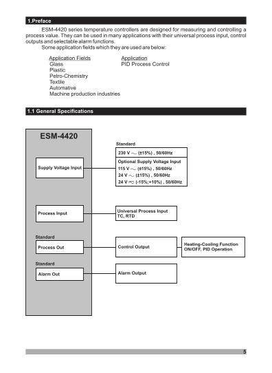
ESM-4420 series temperature controllers are designed for measuring and controlling aprocess value. They can be used in many applications with their universal process input, controloutputs and selectable alarm functions.
Some application fields which they are used are below:
1.Preface
5
ApplicationApplication FieldsGlass PID Process ControlPlasticPetro-ChemistryTextileAutomativeMachine production industries
Alarm Out
Process Input
Supply Voltage Input
1.1 General Specifications
ESM-4420
Standard
Heating-Cooling FunctionON/OFF, PID OperationProcess Out
Alarm Output
Control Output
Universal Process InputTC, RTD
Standard
Standard
230 V (±15 ) , 50/60Hz� %
Optional Supply Voltage Input
115 V (±15 ) , 50/60Hz� %
24 V (±15 ) , 50/60Hz� %
24 V (-15 ) , 50/60Hz%;+10%�

All order information ofE S M - 4 4 2 0 Te m p e r a t u r eController are given on the table atleft. User may form appropriatedev ice conf igura t ion f rominformation and codes that at thetable and convert it to the orderingcodes.
Firstly, supply voltage thenother specifications must bedetermined. Please fill the ordercode blanks according to yourneeds.
Please contact us, if yourneeds are out of the standards.
1.2 Ordering Information
6
���
Vac,
Vdc
Vdc or Vac can be applied
�
�
��
A BC D E FG HI
/
U V W Z/
/0 00
1 Relay Output (resistive load 5A@250V , 1 NO + 1NC)�
Process InputE
Supply VoltageA
ESM-4420 (48x48 DIN 1/16)
24V ( ± %15 ) 50/60Hz�3
115V ( ± %15 ) 50/60Hz�4
230V ( ± %15 ) 50/60Hz�5
9
2 SSR Driver Output (maximum 12V ,10mA)�
Customer
23
25
27
28
29
J ,Fe CuNi IEC584.1(ITS90)
K ,NiCr Ni IEC584.1(ITS90)
R ,Pt13%Rh Pt IEC584.1(ITS90)
S ,Pt10%Rh Pt IEC584.1(ITS90)
T ,Cu CuNi IEC584.1(ITS90)
-200°C,900°C
-200°C,1300°C
0°C,1700°C
0°C,1700°C
-200°C,400°C
-328°F,1652°F
-328°F,2372°F
32°F,3092°F
32°F,3092°F
-328°F,752°F
Input Type(TC) Scale(°C) Scale(°F)BC
01
Alarm OutputFG
/
0 0 0 001
Input TypeBC
Configurable (Table-1)20
Scale
Table-1
Serial CommunicationD
None0
Input Type(RTD) Scale(°C) Scale(°F)BC
PT 100 , IEC751(ITS90)
PT 100 , IEC751(ITS90)
-200°C,650°C
-199.9°C,650.0°C
-328°F,1202°F
-199,9°F,999.9°F
39
40
Table-1
Relay Output (resistive load 5A@250V , 1 NO)�
2 24V ( -15%;+10% ) 50/60Hz�

7
1.3 Warranty
EMKO Elektronik warrants that the equipment delivered is free from defects in material andworkmanship. This warranty is provided for a period of two years. The warranty period starts fromthe delivery date. This warranty is in force if duty and responsibilities which are determined inwarranty document and instruction manual performs by the customer completely.
1.4 Maintenance
Repairs should only be performed by trained and specialized personnel. Cut power to the devicebefore accessing internal parts.Do not clean the case with hydrocarbon-based solvents (Petrol, Trichlorethylene etc.). Use ofthese solvents can reduce the mechanical reliability of the device. Use a cloth dampened in ethylalcohol or water to clean the external plastic case.

8
In package ,- One piece unit- Two pieces mounting clamp- One piece instruction manual
A visual inspection of this product for possible damage occured during shipment isrecommended before installation. It is your responsibility to ensure that qualifiedmechanical and electrical technicians install this product.
If there is danger of serious accident resulting from a failure or defect in this unit, poweroff the system and the electrical connection of the device from the system.
The unit is normally supplied without a power switch or a fuse. Use power switch and fuseas required.
Be sure to use the rated power supply voltage to protect the unit against damage and toprevent failure.
Keep the power off until all of the wiring is completed so that electric shock and troublewith the unit can be prevented.
Never attempt to disassemble, modify or repair this unit. Tampering with the unit mayresults in malfunction, electric shock or fire.
Do not use the unit in combustible or explosive gaseous atmospheres.
During the equipment is putted in hole on the metal panel while mechanical installationsome metal burrs can cause injury on hands, you must be careful.
Montage of the product on a system must be done with it’s mounting clamp. Do not do themontage of the device with inappropriate mounting clamp. Be sure that device will not fallwhile doing the montage.
It is your responsibility if this equipment is used in a manner not specified in thisinstruction manual.
separate
Before beginning installation of this product, please read the instructionmanual and warnings below carefully.
2.Installation
�

2.1 General Description
2.2 Dimensions
9
ESM-4420
ASET
Temperature Controller
PPSET
°C
°F
PO
AO
PS
AS
84 mm / 3.31 inch
48
mm
/1.8
9in
ch
48 mm/ 1.89 inch
Maximum 5 0.2 inchmm /
11 ± 1 mm /0.43 inch
Panel surface(maximum thickness 5mm / 0.2 inch)
Front PanelIp65 protectionNEMA 4X
Mounting Clamps
Product Label

2.3 Panel Cut-Out
10
65
mm
/2
.56
inc
h(m
in)
65 mm / 2.56 inch (min)
46 mm / 1.81 inch (min)
46
mm
/1
.81
inc
h(m
in)

�11
1
2
3
During installation into a metal panel, care should be taken to avoid injury frommetal burrs which might be present. The equipment can loosen from vibrationand become dislodged if installation parts are not properly tightened. Theseprecautions for the safety of the person who does the panel mounting.
1-Before mounting the device in yourpanel, make sure that the cut-out is ofthe right size.
2-Check front panel gasket position
3-Insert the device through the cut-out.If the mounting clamps are on the unit,put out them before inserting the unit tothe panel.
2.4 Environmental Ratings
2.5 Panel Mounting
Operating Temperature :
Max. Operating Humidity :
Altitude :
0 to 50 °C
90 Rh (non-condensing)
Up to 2000m.
%
Operating Conditions
Forbidden Conditions:Corrosive atmosphereExplosive atmosphereHome applications (The unit is only for industrial applications)�

12
�
�
1-Loosen the screws.
2-Pull mounting clamps from top and bottomfixing sockets.
3-Pull the unit through the front side of the panel
Before starting to remove the unit from panel, power off the unit and the relatedsystem.
Montage of the unit to a system must be done with it’s own fixing clamps. Do notdo the montage of the device with inappropriate fixing clamps. Be sure thatdevice will not fall while doing the montage.
The unit is designed for panel mounting.
1-Insert the unit in the panel cut-out from thefront side.
2- Insert the mounting clamps to the holes thatlocated top and bottom sides of device andscrew up the fixing screws until the unitcompletely immobile within the panel
2.6 Installation Fixing Clamp
2.7 Removing from the Panel
12
3
21

13
Max. 2.5mm / inchWire Size:14AWG/1mm²Solid /Stranded
�
3.1 Terminal Layout and Connection Instructions
Torque 0.5 Nm
Screw driver 0.8x3mm
You must ensure that the device is correctly configured for your application.Incorrect configuration could result in damage to the process being controlled,and/or personal injury. It is your responsibility, as the installer, to ensure thatthe configuration is correct.Parameters of the device has factory default values. These parameters must beset according to the system’s needs.
Only qualified personnel and technicians should work on this equipment. Thisequipment contains internal circuits with voltage dangerous to human life.There is severe danger for human life in the case of unauthorized intervention.
Be sure to use the rated power supply voltage to protect the unit againstdamage and to prevent failure.
Keep the power off until all of the wiring is completed so that electric shock andtrouble with the unit can be prevented.
3.Electrical Wirings
�
�
�
�

230
115
V ( ± 15% ) 50/60Hz - 3VA
V ( ± 15% ) 50/60Hz - 3VA
24V ( ± 15% ) 50/60Hz - 3VA
���
3.2 Electrical Wiring Diagram
�
14
13�NOC
5A@250V�ALARM OUT
Supply Voltage Input
(It must be determinedin order.)
Alarm Output Relay
CAT II�
P/N : 442ESM- 0�
8 9 10 11 12 14
Temperature measurement input is in CAT II class.i
UniversalTemperature Measurement Input
(TC, RTD)
TC
Pt-100
1 2 3
NO C NC
PROCESS OUT
5A@250V�
Process OutputRelay or
Optional SSR Output
N LNote-1
Note-1: SSR Driver OutputMax 12V ,10mA for�
( )+( )-
(It must be determinedin order.)
Electrical wiring of the device must be the same as ‘Electrical Wiring Diagram’below to prevent damage to the process being controlled and personnel injury.
24V ( - 15%;+10% ) 50/60Hz - 3VA�

15
3.3 View of the Device Label
PROCESS OUT
N L5A@250V�
P/N : ESM-4420
��� CAT IITC
Pt-100
NOC
7654321
141312111098NCNO C
ALARM OUT5A@250V� 230V ±15%�
50/60Hz 3VA
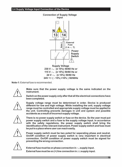
3.4 Supply Voltage Input Connection of the Device
16
Note-1: External fuse is recommended.
Supply voltage range must be determined in order. Device is produceddifferent for low and high voltage. While installing the unit, supply voltagerange must be controlled and appropriate supply voltage must be applied tothe unit. Controlling prevents damages in unit and system and possibleaccidents as a result of incorrect supply voltage.
There is no power supply switch or fuse on the device. So the user must putpower supply switch and a fuse to the supply voltage input. In accordancewith the safety regulations, the power supply switch shall bring theidentification of the relevant instrument. Power supply switch and fuse mustbe put to a place where user can reach easily.
�
Power supply switch must be two poled for seperating phase and neutral.On/Off condition of power supply switch is very important in electricalconnection. On/Off condition of power supply switch must be signed forpreventing the wrong connection.
External fuse must be on phase connection in supply input.�
�
�
�
Make sure that the power supply voltage is the same indicated on theinstrument.
Switch on the power supply only after that all the electrical connections havebeen completed.
�
Connection of Supply VoltageInput
Supply Voltage
230 V (± 15%) 50/60 Hz or
115 V (± 15%) 50/60 Hz or
24 V (± 15%) 50/60 Hz
24V ( - 15%;+10% ) 50/60Hz
���
�
13N L
14
�
PowerSupplySwitch
�
�
ExternalFuse
(1 A T)�No
te-1
External fuse must be on (+) line connection in supply input.�

17
3.5 Process Input Connection
3.5.2 RTD Connection
Note 1 :
Note 2 :Note 3 :
In 3-wire system, use always cables of the same diameter (min 1mm²) Always usewires of the same gauge and type whether a 2-wire or 3-wire system.
Install a jumper between terminals 2 and 3 when using a 2-wire RTD.If the distance is longer than 10 meters, use 3-wire system
3-wire Pt-100 connection(with line compensation)
(Max. Line impedance is 10 )�
2-wire Pt-100 connection(without line compensation)
1 12 23 3
Pt-100
Note 1 Note 2
Pt-100
3.5.1 TC (Thermocouple) Connection
1 2 3
TCConnect the wires with the polarity as shown in thefigure left.
Always use compensation wire corresponding to the thermocouple used. Ifpresent, the shield must be connected to a proper ground.i
Input resistance is greater than 10M ��i
Input resistance is greater than 10M ��i

18
3.6 Galvanic Isolation Test Values of ESM-4420 Temperature Controller
2000 ( ESM-4420 )
5
V For .5.....�00V ( For ESM-4420.3..... )�
13
14Ground 1
8
9
9
10
2000V�
2000V�
2000V�
2000V�
2000V�
2
3
2000V�
10
11
12
8
9
10
9
10
11
12
2
3
Supply Voltage
Process Output(Relay)
Process Output(SSR Driver)
Alarm Output(Relay)
AnalogInputs

4. Output Connection Forms in ESM- Temperature Controller4420
4.1 Process Output ( Relay ) Connection
19
Fuse
Load
Last ControlElement
(SSR)
9
DeviceL N
10
Fuses must be selected according to the application.�
�12 V
Max. 10mA�
Fuses must be selected according to the application.�
Device
9
8
Fuse
Load
L N
Last Control Element(Contactor)
�
10
5A T Fuse�C
NC
NO
4.2 Process Output ( SSR Driver ) Connection

4.3 Alarm Output ( Relay ) Connection
20
Fuses must be selected according to the application.�
Device
11
12
Fuse
Load
L N
Last Control Element(Contactor)
�
5A T Fuse�
NO
C

ESM-4420
ASET
Temperature Controller
PPSET
°C
°F
PO
AO
PS
AS
5.1 Front Panel Definition
Process Output Status Led
Alarm Output Status Led
This button is used to accessto the process set value. If it
is pressed for 5 secondscontinuously programming
section is entered.
This button is used toaccess to the alarm set
value and use as OKbutton.
5. Front Panel Definition and Accessing to the Menus
21
PS , Process SetValue LEDAS , Alarm SetValue LED
Note-1
Displays Set ValueParameter
,
Please refer to Section 6.1for detailed information;Section 6.1 (Process andAlarm Set Parameters)
This button is used toincrease the parametervalues and access tothe program menus
This button is used todecrase the parametervalues, access to the
program menus
LED indication of °C:Centigrade Unit
LED indication of °FFahrenheit Unit
DisplaysProcess Value (PV)and Parameter
Note-1
Note-1: If increment or decrement button is pressed for 5 seconds continuously,increment and decrement number become 10, if increment or decrement button ispressed for 10 seconds continuously, increment and decrement number become 100.
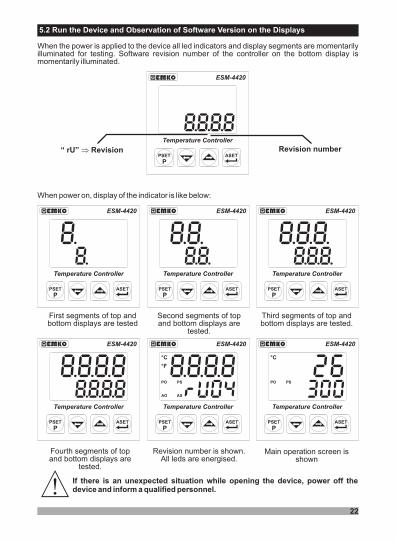
When the power is applied to the device all led indicators and display segments are momentarilyilluminated for testing. Software revision number of the controller on the bottom display ismomentarily illuminated.
5.2 Run the Device and Observation of Software Version on the Displays
22
When power on, display of the indicator is like below:
First segments of top andbottom displays are tested
Second segments of topand bottom displays are
tested.
Third segments of top andbottom displays are tested.
Fourth segments of topand bottom displays are
tested.
Revision number is shown.All leds are energised.
Main operation screen isshown
If there is an unexpected situation while opening the device, power off thedevice and inform a qualified personnel.�
ESM-4420
ASET
Temperature Controller
PPSET
°C
°F
PO
AO
PS
AS
ESM-4420
ASET
Temperature Controller
PPSET
°C
°F
PO
AO
PS
AS
ESM-4420
ASET
Temperature Controller
PPSET
°C
°F
PO
AO
PS
AS
ESM-4420
ASET
Temperature Controller
PPSET
°C
°F
PO
AO
PS
AS
ESM-4420
ASET
Temperature Controller
PPSET
°C
°F
PO
AO
PS
AS
ESM-4420
ASET
Temperature Controller
PPSET
°C
°F
PO
AO
PS
AS
ESM-4420
ASET
Temperature Controller
PPSET
°C
°F
PO
AO
PS
AS
“ rU” Revision� Revision number

23
5.3 Adjustment of Process SET Value
When PSET button is pressed, PSled starts to blink, the information toindicate which set is shown is on topdisplay, process set value is shown
on bottom display.
Change the process setvalue with increment and
decrement buttons.
Press ASET/OK button for savingprocess set value.
Press PSET button to exit withoutsaving the process set value.
ProcessSet Screen
OperationScreen
OperationScreen
ASET
PPSET
°C
°F
PO
AO
PS
AS
ASET
PPSET
°C
°F
PO
AO
PS
AS
ASET
PPSET
°C
°F
PO
AO
PS
AS
ASET
PPSET
°C
°F
PO
AO
PS
AS
ASET
PPSET
°C
°F
PO
AO
PS
AS
OperationScreen
5.4 Adjustment of Alarm SET Value
Change alarm set valuewith increment anddecrement buttons.
Press ASET/OK button forsaving process set value.
Press PSETbutton to exit
withoutsaving thealarm set
value.
Alarm SetScreen
OperationScreen
ASET
PPSET
°C
°F
PO
AO
PS
AS
ASET
PPSET
°C
°F
PO
AO
PS
AS
ASET
PPSET
°C
°F
PO
AO
PS
AS
ASET
PPSET
°C
°F
PO
AO
PS
AS
Operation Screen
Value, can be adjustedfrom process set low limit
To process set highlimit .
value can be adjustedfrom alarm set low limitto alarm set high limit .
When ASET button is pressed, ASled starts to blink, the information toindicate which set is shown is on topdisplay, alarm set value is shown on
bottom display.

6. Parameters
24
6.1 Parameter List
Process menu title
J type (Fe,Cu,Ni) Thermocouple, or-200°C,900°C -328°F,1652°F
Process input type selection ( Default Value = J Type (FE.C.n) )
Pt - 100 , -199.9°C,650.0°C or -199.9°F,999.9°F
K type (Ni,Cr,Ni) Thermocouple , -200°C,1300°C or -328°F,2372°F
R type (Pt13%RhPt) Thermocouple , 0°C,1700°C or 32°F,3092°F
S type (Pt10%RhPt) Thermocouple, 0°C,1700°C or 32°F,3092°F
T type (Cu,Cu,Ni) Thermocouple , -200°C,400°C or -328°F,752°F
Pt - 100 , -200°C,650°C or -328°F,1202°F
Unit is °C
Unit Selection ( Default Value = °C )
Unit is °F
Process Set Low Limit. Minimum process set value is defined with this parameter.It changes according to process input type and scale. ( Default Value = -200 )
Process Set High Limit. Maximum process set value is defined with this parameter.It changes according to process input type and scale. ( Default Value = 900 )
Control menu title
Self - Tune (Step Response Tuning) does not run. (Please refer to Section 7.1 forTune Operation)
Tune parameter ( Default Value = no )CntS PýdThis parameter can be observed if parameter is
Self - Tune runs (Step Response Tuning) .
Process type is heating
Process Type selection ( Default Value = Heat )
Process type is cooling
Process Control form is ON/OFF
Process Control Type selection ( Default Value = on.oF )
Process Control form is PID
Display offset for process value.It can be adjusted from -10% of scale ( PuPL- PLoL ) to 10% of scale( PuPL- PLoL ). Itis added to the process display value. ( Default Value = 0 )

25
Alarm menu title
Alarm Hysteresis value.It can be adjusted from 0% of defined scale (AuPL-ALoL) to 50% of defined scale(AuPL-ALoL). ( Default Value = 0 )
Output Control period. It can be adjusted from 1 to 150 seconds.If process control type selection , then this parameter can be observedCntS = Pýd( Default Value = 10 )
Hysteresis value.If Process Control Type selection then this parameter can beobserved. It can be adjusted from 0% of defined scale ( PuPL- PLoL ) to 50% ofdefined scale ( PuPL- PLoL).
CntS = on.oF,
( Default Value = 0 )
Process High Alarm
Alarm Type selection ( Default Value = PHýA(Process HighAlarm) )
Process Low Alarm
Deviation High Alarm
Deviation Low Alarm
Deviation Band Alarm
Deviation Range Alarm
Alarm Set Value Low Limit. Minimum value of the alarm set value is defined in thisparameter.It can be adjusted from process set value low limit parameter to alarm set high limitparameter. It changes according to process input type and scale( Default Value = 0 )
Alarm Set High Limit. Maximum value of the alarm set value is defined in thisparameter.It can be adjusted from alarm set low limit parameter to process set high limitparameter.It changes according to process input type and scale( Default Value = 500 )
Alarm on delay time.It can be adjusted from 0 to 9999 seconds. ( Default Value = 0 )
Alarm off delay time.It can be adjusted from 0 to 9998 seconds. When it is higher than 9998, “LtCH” isshown and alarm latching output is selected. To make the alarm latching outputpassive, decrement button must be pressed in main operation screen.( Default Value = 0 )
Protection menu title
Password for accessing to the programming section. It can be adjusted from 0 to9999. ( Default Value = 0 )
Proportional Band . It can be adjusted from 1.0% to 100.0%.If process control type selection , then this parameter can be observed
( Default Value = 10.0 )
CntS = Pýd
Integral Time. It can be adjusted from 0 to 3600 secs.If process control type selection , then this parameter can be observedCntS = Pýd( Default Value = 100 )
Derivative Time. It can be adjusted from 0.0 to 999.9 secs.If process control type selection , then this parameter can be observedCntS = Pýd( Default Value = 25.0 )

26
6.2 ParametersEasy Access Diagram of
For entering to theprogramming section, press
PSET/P button for 5seconds.
Password enteringscreen is shown when
ASET/OK Button ispressed.
Enter the password withincrement or decrement
buttons.
°C
°F
PO
AO
PS
AS
PPSET
Controlmenu
ProportionalBand
IntegralTime
Derivative Time
Control Period
HysteresisValue
Alarmmenu
Alarm HysteresisValue
Alarm Type selection
Alarm LowLimit
Alarm HighLimit
Alarm OnTime
Alarm Offtime
ProtectionMenu
Programming SectionEntering Password
°C
°F
PO
AO
PS
AS
PPSET
°C
°F
PO
AO
PS
AS
ASET
After 5secs°C
°F
PO
AO
PS
AS
°C
°F
PO
AO
PS
AS
ASET
Password Entering ScreenMain Operation
Screen
°C
°F
PO
AO
PS
AS
ASET
°C
°F
PO
AO
PS
AS
ASET
°C
°F
PO
AO
PS
AS
ASET
°C
°F
PO
AO
PS
AS
ASET
°C
°F
PO
AO
PS
AS
ASET
°C
°F
PO
AO
PS
AS
ASET
°C
°F
PO
AO
PS
AS
ASET
°C
°F
PO
AO
PS
AS
ASET
°C
°F
PO
AO
PS
AS
ASET
°C
°F
PO
AO
PS
AS
ASET
°C
°F
PO
AO
PS
AS
ASET
°C
°F
PO
AO
PS
AS
ASET
°C
°F
PO
AO
PS
AS
ASET
°C
°F
PO
AO
PS
AS
ASET
°C
°F
PO
AO
PS
AS
ASET
Process Type Selection
°C
°F
PO
AO
PS
AS
ASET
Process Control Type Selection°C
°F
PO
AO
PS
AS
ASET
°C
°F
PO
AO
PS
AS
ASET
Processmenu
Process InputType selection
Unit Selection
Process Set LowLimit
Process Set HighLimit
ProcessOffset Value
°C
°F
PO
AO
PS
AS
ASET
°C
°F
PO
AO
PS
AS
ASET
°C
°F
PO
AO
PS
AS
ASET
°C
°F
PO
AO
PS
AS
ASET
°C
°F
PO
AO
PS
AS
ASET
°C
°F
PO
AO
PS
AS
ASET
Tuneparameter
°C
°F
PO
AO
PS
AS
ASET
°C
°F
PO
AO
PS
AS
ASET
Press ASET/OKbutton for enteringto the menus.

27
OperationScreen
Press PSET/P button for 5seconds for enteringprogramming section
ASET
PPSET
°C
°F
PO
AO
PS
AS
ASET
PPSET
°C
°F
PO
AO
PS
AS
When 5secs is expired,programming section
entering screen is shown.
ASET
PPSET
°C
°F
PO
AO
PS
AS
ProgrammingSection Entering
Screen
Press ASET/OK button for accessing to the password entering screen.
ASET
PPSET
°C
°F
PO
AO
PS
AS
If password forentering to theprogramming
section isdefined,
passwordenteringscreen isshown.
Enter the passwordwith increment or
decrement buttons.
ASET
PPSET
°C
°F
PO
AO
PS
AS
When screen is shown,parameters can be observedby pressing ASET/OK button
without entering thepassword. But no changes
can be done with theparameters. Please refer to
Section 6.6 (Protection Menu)for detailed information
PressASET/OKbutton forentering tothe menus.
ASET
PPSET
°C
°F
PO
AO
PS
AS
Process Menu
ASET
PPSET
°C
°F
PO
AO
PS
AS
Control Menu
Following menu can be accessby pressing right arrow button.
Former menu can be accessedby pressing left arrow button.
ASET
PPSET
°C
°F
PO
AO
PS
AS
Protection Menu
Press ASET/OK button foraccessing to the Process
Menu.
6.3 Entering to the Programming Section and Process Menu
28
ASET
PPSET
°C
°F
PO
AO
PS
AS
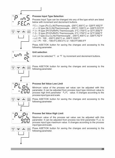
Process Set Value Low Limit
Minimum value of the process set value can be adjusted with thisparameter. It can be adjusted from process input type minimum value toprocess high limit parameter value. It changes according to theprocess input type and scale.
ASET
PPSET
°C
°F
PO
AO
PS
AS
Process Set Value High Limit
Maximum value of the process set value can be adjusted with thisparameter. It can be adjusted from process low limit parameter toprocess input type maximum value. It changes according to the processinput type and scale.
ASET
PPSET
°C
°F
PO
AO
PS
AS
Process Input Type Selection
Process Input Type can be changed into any of the type which are listedbelow with increment and decrement buttons.
ASET
PPSET
°C
°F
PO
AO
PS
AS
Unit selection
Unit can be selected or by increment and decrement buttons.
Press ASET/OK button for saving the changes and accessing to thefollowing parameter.
: J type Thermocouple, or(Fe,Cu,Ni): K type (Ni,Cr,Ni)Thermocouple ,: R type (Pt13%RhPt) Thermocouple,: S type (Pt10%RhPt) Thermocouple,: T type (Cu,Cu,Ni)Thermocouple ,: Pt - 100 ,: Pt - 100 ,
-200°C,900°C -328°F,1652°F-200°C,1300°C or -328°F,2372°F
0°C,1700°C or 32°F,3092°F0°C,1700°C or 32°F,3092°F
-200°C,400°C or -328°F,752°F-200°C,650°C or -328°F,1202°F-199.9°C,650.0°C or -199.9°F,999.9°F
Press ASET/OK button for saving the changes and accessing to thefollowing parameter.
Press ASET/OK button for saving the changes and accessing to thefollowing parameter.
Press ASET/OK button for saving the changes and accessing to thefollowing parameter.
29
ASET
PPSET
°C
°F
PO
AO
PS
AS
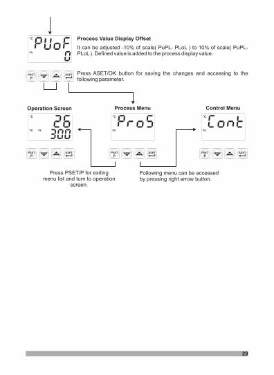
Process Value Display Offset
It can be adjusted -10% of scale to 10% of scale.
( PuPL- PLoL ) ( PuPL-PLoL) Defined value is added to the process display value.
ASET
PPSET
°C
°F
PO
AO
PS
AS
Process MenuOperation Screen
ASET
PPSET
°C
°F
PO
AO
PS
AS
Control Menu
Press PSET/P for exitingmenu list and turn to operation
screen.
ASET
PPSET
°C
°F
PO
AO
PS
AS
Following menu can be accessedby pressing right arrow button.
Press ASET/OK button for saving the changes and accessing to thefollowing parameter.
30
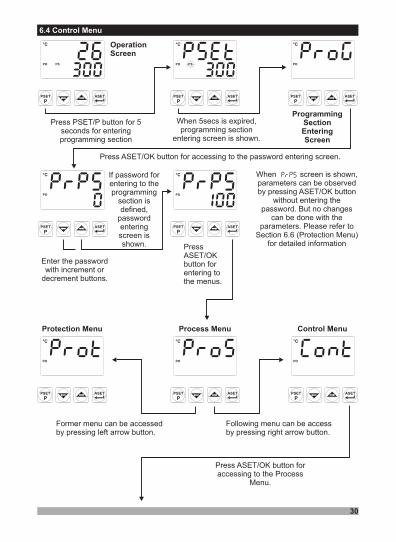
6.4 Control Menu
OperationScreen
Press PSET/P button for 5seconds for enteringprogramming section
ASET
PPSET
°C
°F
PO
AO
PS
AS
ASET
PPSET
°C
°F
PO
AO
PS
AS
When 5secs is expired,programming section
entering screen is shown.
ASET
PPSET
°C
°F
PO
AO
PS
AS
ProgrammingSectionEnteringScreen
Press ASET/OK button for accessing to the password entering screen.
ASET
PPSET
°C
°F
PO
AO
PS
AS
If password forentering to theprogramming
section isdefined,
passwordenteringscreen isshown.
ASET
PPSET
°C
°F
PO
AO
PS
AS
ASET
PPSET
°C
°F
PO
AO
PS
AS
Process Menu
ASET
PPSET
°C
°F
PO
AO
PS
AS
Control Menu
ASET
PPSET
°C
°F
PO
AO
PS
AS
Protection Menu
When screen is shown,parameters can be observedby pressing ASET/OK button
without entering thepassword. But no changes
can be done with theparameters. Please refer to
Section 6.6 (Protection Menu)for detailed informationPress
ASET/OKbutton forentering tothe menus.
Enter the passwordwith increment or
decrement buttons.
Following menu can be accessby pressing right arrow button.
Former menu can be accessedby pressing left arrow button.
Press ASET/OK button foraccessing to the Process
Menu.

31
ASET
PPSET
°C
°F
PO
AO
PS
AS
31
ASET
PPSET
°C
°F
PO
AO
PS
AS
Process Type Selection
Process Type Selection can be selected or with increment anddecrement buttons.
PressASET/OK button for saving the parameter and accessing to the nextparameter.
ASET
PPSET
°C
°F
PO
AO
PS
AS
Hysteresis ValueProcess Con t ro l Typeselection.If = ,thenthis parameter can beobserved.It can be adjustedfrom 0% of full scale (PuPL-PLoL) to 50% of full scale(PuPL-PLoL) with incrementand decrement buttons.
ASET
PPSET
°C
°F
PO
AO
PS
AS
Process Control TypeSelection
Process Control Type can beselected or withincrement and decrementbuttons.
Press ASET/OK button forsaving the parameter andaccessing to the nextparameter.
If Process Control Typeselection = ,parameter is saved andexit from control menu byp r e s s i n g A S E T / O Kbutton.
ASET
PPSET
°C
°F
PO
AO
PS
AS
Control Menu
ASET
PPSET
°C
°F
PO
AO
PS
AS
TuneParameter
Tune operationcan be startedand stoppedwith incrementand decrementbuttons. IfProcess ControlType is
Then thisparameter canbe observed.
Press ASET/OKbutton for saving thep a r a m e t e r a n daccessing to thenext parameter.
ASET
PPSET
°C
°F
PO
AO
PS
AS
Press ASET/OKbutton for savingthe parameterand accessingt o t h e n e x tparameter.
ProportionalBand
Proportional band can be adjusted from 1.0% to100.0% with increment and decrement buttons. IfProcess Control Type selection
= , then this parameter can be observed.For example ;If = 1000°C, = 0°C and = 50.0Proportional Band = ( - ) * /100.0Proportional Band = ( 1000 - 0 ) * 50.0 /100.0 = 500 °C
Press ASET/OKbutton for savingthe parameterand accessingt o t h e n e x tparameter.

32
ASET
PPSET
°C
°F
PO
AO
PS
AS
Output Control Period
It can be adjusted from 1 to 150 with increment and decrement buttons.If Process Control Type selection = , then this parametercan be observed.
ASET
PPSET
°C
°F
PO
AO
PS
AS
Control Menu
ASET
PPSET
°C
°F
PO
AO
PS
AS
Alarm Menu
Next menu can be accessed bypressing right-arrow button.
Former menu can be accessedby pressing left-arrow button.
ASET
PPSET
°C
°F
PO
AO
PS
AS
Process Menu
Press PSET/P button to exit from menu list andturn to the operation screen.
OUTPUT : ON
OUTPUTPERIOD
OUTPUTPERIOD
Relay Output :
SSR Output :
Output period must be short forstable process control. Relay must not be usedin short output periods because of limited life oftheir relay contact (number of open/closeevents). Relay output must be used as controloutput in values near to 30 seconds or greaterthan this value.
If short output period is neededin a system (approximately 1-2 seconds) SSRdriver output module as last control
P r e s s A S E T / O Kbutton for saving thep a r a m e t e r a n daccessing to the nextparameter.
ASET
PPSET
°C
°F
PO
AO
PS
AS
Integral Time
It can be adjusted from 0 to 3600 seconds with increment and decrementbuttons.If Process Control Type selection = , then this parametercan be observed.
ASET
PPSET
°C
°F
PO
AO
PS
AS
Derivative Time
It can be adjusted from 0.0 to 999.9 seconds.If Process Control Type selection = , then this parametercan be observed.
Press ASET/OK button to save the value and access to the nextparameter.
PressASET/OK button for saving the parameter and accessing to the nextparameter.

33
6.5 Alarm Menu
OperationScreen
ASET
PPSET
°C
°F
PO
AO
PS
AS
ASET
PPSET
°C
°F
PO
AO
PS
AS
ASET
PPSET
°C
°F
PO
AO
PS
AS
ASET
PPSET
°C
°F
PO
AO
PS
AS
ASET
PPSET
°C
°F
PO
AO
PS
AS
ASET
PPSET
°C
°F
PO
AO
PS
AS
Process Menu
ASET
PPSET
°C
°F
PO
AO
PS
AS
Control Menu
ASET
PPSET
°C
°F
PO
AO
PS
AS
Protection Menu
Press PSET/P button for 5seconds for enteringprogramming section
When 5secs is expired,programming section
entering screen is shown.
ProgrammingSectionEnteringScreen
Press ASET/OK button for accessing to the password entering screen.
If password forentering to theprogramming
section isdefined,
passwordenteringscreen isshown.
Enter the passwordwith increment or
decrement buttons.
PressASET/OKbutton forentering tothe menus.
When screen is shown,parameters can be observedby pressing ASET/OK button
without entering thepassword. But no changes
can be done with theparameters. Please refer to
Section 6.6 (Protection Menu)for detailed information
Following menu can be accessby pressing right arrow button.
Former menu can be accessedby pressing left arrow button.
Press ASET/OK button foraccessing to the Process
Menu.

34
ASET
PPSET
°C
°F
PO
AO
PS
AS
Alarm Menu
ASET
PPSET
°C
°F
PO
AO
PS
AS
Alarm Hysteresis value
Press ASET/OK button for accessing to the alarm menu.
ASET
PPSET
°C
°F
PO
AO
PS
AS
Alarm Type Selection
: Process High Alarm: Process Low Alarm: Deviation High Alarm: Deviation Low Alarm: Deviation Band Alarm: Deviation Range Alarm
Please refer to Section 7.2 Alarm Types for detailed information
It can be adjusted to the values listed below:
ASET
PPSET
°C
°F
PO
AO
PS
AS
Alarm Set Low Limit Value
Minimum value of the alarm set is defined with this parameter. Itchanges according to the process type and scale. It can be adjustedfrom process set value low limit parameter to alarm set high limitparameter value.
It can be adjusted from 0% of (AuPL-ALoL) to 50% of (AuPL-ALoL).
Press ASET/OK button for saving the changes and accessing to thefollowing parameter.
Press ASET/OK button for saving the changes and accessing to thefollowing parameter.
Press ASET/OK button for saving the changes and accessing to thefollowing parameter.

35
ASET
PPSET
°C
°F
PO
AO
PS
AS
Alarm On Delay Time
It can be adjusted from 0 to 9999 seconds with increment and decrementbuttons.
ASET
PPSET
°C
°F
PO
AO
PS
AS
Alarm Set High Limit Value
Maximum value of alarm set is defined with this parameter. It can beadjusted from alarm set low limit parameter to process set highlimit parameter . It changes according to process input type andscale.
ASET
PPSET
°C
°F
PO
AO
PS
AS
Alarm OFF Delay Time
It can be adjusted from 0 to 9998 seconds. When it is higher than 9998,is shown and alarm latching output is selected.To make the alarm
latching output passive, decrement button must be pressed in mainoperation screen.
ASET
PPSET
°C
°F
PO
AO
PS
AS
Alarm Menu
ASET
PPSET
°C
°F
PO
AO
PS
AS
Protection Menu
ASET
PPSET
°C
°F
PO
AO
PS
AS
Control Menu
Press PSET/P for exiting menu list and turn tooperation screen.
AlarmStatus
AlarmOutput
OnDelay
OFFDelay
Press ASET/OK button for saving the changes and accessing to thefollowing parameter.
Press ASET/OK button for saving the changes and accessing to thefollowing parameter.
Press ASET/OK button for saving the changes and accessing to thefollowing parameter.
Following menu can be accessby pressing right arrow button.
Former menu can be accessedby pressing left arrow button.
Press ASET/OK button foraccessing to the Process
Menu.
36
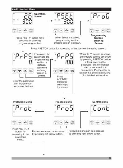
6.6 Protection Menu
OperationScreen
ASET
PPSET
°C
°F
PO
AO
PS
AS
ASET
PPSET
°C
°F
PO
AO
PS
AS
ASET
PPSET
°C
°F
PO
AO
PS
AS
ASET
PPSET
°C
°F
PO
AO
PS
AS
ASET
PPSET
°C
°F
PO
AO
PS
AS
ASET
PPSET
°C
°F
PO
AO
PS
AS
Process Menu
ASET
PPSET
°C
°F
PO
AO
PS
AS
Control Menu
ASET
PPSET
°C
°F
PO
AO
PS
AS
Protection Menu
Press ASET/OKbutton for
accessing to theprotection
menu.
ProgrammingSectionEnteringScreen
Press PSET/P button for 5seconds for enteringprogramming section
When 5secs is expired,programming section
entering screen is shown.
When screen is shown,parameters can be observedby pressing ASET/OK button
without entering thepassword. But no changes
can be done with theparameters. Please refer to
Section 6.6 (Protection Menu)for detailed information
Press ASET/OK button for accessing to the password entering screen.
Following menu can be accessedby pressing right arrow button.
Former menu can be accessedby pressing left arrow button.
Enter the passwordwith increment or
decrement buttons.
If password forentering to theprogramming
section isdefined,
passwordenteringscreen isshown. Press
ASET/OKbutton forentering tothe menus.

37
ASET
PPSET
°C
°F
PO
AO
PS
AS
Programming Section Entering Password
ASET
PPSET
°C
°F
PO
AO
PS
AS
Protection Menu
ASET
PPSET
°C
°F
PO
AO
PS
AS
Process Menu
ASET
PPSET
°C
°F
PO
AO
PS
AS
Alarm Menu
Press PSET/P for exitingmenu list and turn to
operation screen.
It is used for accessing to the programming section. It can be adjusted from0 to 9999.If it is 0, programming section is accessed without entering the password.
If it is different from 0, in programming section entering password;1-
2-
If user enters the password incorrect:Device turns to main operation screen without being able to see theparameters
If user press theASET/OK button without entering the passwordfor entering to the programming section (observation of the parameters):All menus and parameters except protection menu ( ) can be observedbut they can not be changed.(Please refer to Section 8. Failure Messages in ESM-4420 TemperatureController(4))
Operation Screen
ASET
PPSET
°C
°F
PO
AO
PS
AS
Press ASET/OKbutton for saving
the parameterand exiting fromprotection menu
parameters.
Following menu can be accessby pressing right arrow button.
Former menu can be accessedby pressing left arrow button.

38
7. General Information
7.1 Tune Operation
Esm-XX20 devices use (Step Response Tuning) method to automatically determinePID parameters.
Self Tune
Starting the Tune operation by the user�
�
�
Enter to the programming sectionSelect the parameter in menu, and turn to main operation screen.Observe that is blinking in set display
OperationScreen
ASET
PPSET
°C
°F
PO
AO
PS
AS
ASET
PPSET
°C
°F
PO
AO
PS
AS
ASET
PPSET
°C
°F
PO
AO
PS
AS
ASET
PPSET
°C
°F
PO
AO
PS
AS
ASET
PPSET
°C
°F
PO
AO
PS
AS
ASET
PPSET
°C
°F
PO
AO
PS
AS
Process Menu
ASET
PPSET
°C
°F
PO
AO
PS
AS
Control Menu
Press ASET/OK button foraccessing to the Control Menu
ProgrammingSectionEnteringScreen
Press PSET/P button for 5seconds for enteringprogramming section
When 5secs is expired,programming section
entering screen is shown.
When screen is shown,parameters can be observedby pressing ASET/OK button
without entering thepassword. But parameters
can not be changed. Pleaserefer to Section 6.6
(Protection Menu) for detailedinformation
Press ASET/OK button for accessing to the password entering screen.
If password forentering to theprogramming
section isdefined,
passwordenteringscreen isshown.
Enter the passwordwith increment or
decrement buttons.
PressASET/OKbutton forentering tothe menus.
Following menu can be accessedby pressing right arrow button.

ASET
PPSET
°C
°F
PO
AO
PS
AS
ASET
PPSET
°C
°F
PO
AO
PS
AS
ASET
PPSET
°C
°F
PO
AO
PS
AS
39
ASET
PPSET
°C
°F
PO
AO
PS
AS
TuneParameter
ASET
PPSET
°C
°F
PO
AO
PS
AS
Change Tune Parameter asWith increment button.
ASET
PPSET
°C
°F
PO
AO
PS
AS
Press ASET/OK button forsaving the parameter.
Press PSET/Pbutton to exit from
the parameterssection and turn
to main operationscreen.
OperationScreen
ASET
PPSET
°C
°F
PO
AO
PS
AS
“Tune” and PSET value isshown on the main operationscreen following one another.
ASET
PPSET
°C
°F
PO
AO
PS
AS
Press PSET/P button to turn to themain operation screen.
Proportional Band
ProcessTypeSelection
Press ASET/OK button forsaving the parameter andaccessing to the nextparameter.
Process Control Type Selection
Change Process ControlType as with increment
button.
P r e s s A S E T / O Kbutton for saving thep a r a m e t e r a n daccessing to the nextparameter.
If operation is finished without any problem, device saves new PID parameters tomemory and runs. It changes parameter to
Self Tune
Canceling operation :If sensor breaks ;If operation can not be completed in 8 hours ;While operation is running, if user changes process set value;
. Then device continues to run with former PID parameterswithout changing PID parameters.
Self Tune1-2- Self Tune3- Self TuneSelf Tune operation is canceled

40
If power is off while operation continues, PID parameters and parameter arenot changed. When power is off and then on, device starts to complete the operation.
Self TuneSelf Tune
iFor starting Tune ( Step Response Tuning ) operation1-2-
3-
:Control form must be P,PI,PD or PID.For heating tune, Process Value must be 5% of full scale lower than process set
valueFor cooling tune, process value must be 5% of full scale higher than process setvalue.
If Process Set Value is changed while Tune operation continues, tune operationis canceled.
If heating function and PID control form is selected for the system;If set value is greater than process value, process output becomes active till to the
value. When process value reaches to this value,process output reduces to 0% and it calculates the PID coefficients.Temperature+[(Set - Temperature) / 2]
% 100
ProcessOutput
ProcessValue
Time
TunEStartValue
PID coefficients are determinedand system becomes stable
Start Value + [ ( Set - Start Value) ]
2
Process SetValue ( )
If cooling function and PID control form is selected for the system;If set value is less than process value, process output becomes active till to the
value. When process value reaches to this value,process output is reduced to 0% and it starts to calculate PID coefficients.Temperature - [( Temperature - Set ) / 2]
ProcessValue
Time
% 100
ProcessOutput
TunEStartValue
Process SetValue ( )
Start Value - [ ( Start Value - Set ) ]
2
PID coefficient aredetermined

41
7.2 Alarm Types
Alarm types which are explained in Section 6.5 Alarm Types Selection parameter areexplained below:
Process HighAlarm
Process LowAlarm
Deviation HighAlarm
Deviation LowAlarm
ON
OFF
AlarmOutput
Process Value
ON
OFF
AlarmOutput
Process Value
ON
OFF
AlarmOutput
Process Value
( + )
ON
OFF
AlarmOutput
Process Value
( - )
ASET
PPSET
°C
°F
PO
AO
PS
AS
ASET
PPSET
°C
°F
PO
AO
PS
AS
ASET
PPSET
°C
°F
PO
AO
PS
AS
ASET
PPSET
°C
°F
PO
AO
PS
AS

ASET
PPSET
°C
°F
PO
AO
PS
AS
ASET
PPSET
°C
°F
PO
AO
PS
AS
42
Deviation BandAlarm
Deviation RangeAlarm
ON
OFF
AlarmOutput
Process Value
( + )( - )
ON
OFF
AlarmOutput
Process Value
( + )( - )

°C
°F
PO
AO
PS
AS
ASET
PPSET
8. Failure Messages in ESM- Temperature Controller4420
43
Please refer to Section 6.3 for detailedinformation about the parameteri
1- Sensor failure in analog inputs. Sensor connection is wrong or there is nosensor connection.
For this example in menu= ; = ; = and=
2- If value that is read from the analog input is lowerthan process set low limit parameter , value onthe top display starts to blink like on the picture.
4- If programming section entering password is different from “0” and useraccesses to the parameter by ASET/OK button without entering thepassword and wants to change a parameter, the warning message is shownon the bottom display as shown on the left. Device does not allow to do anychanges without entering the password correctly.
°C
°F
PO
AO
PS
AS
ASET
PPSET
°C
°F
PO
AO
PS
AS
ASET
PPSET
3- If value that is read from the analog input is higherthan process set high limit parameter value ,value on the top display starts to blink like on thepicture.
°C
°F
PO
AO
PS
AS
ASET
PPSET
°C
°F
PO
AO
PS
AS
ASET
PPSET
°C
°F
PO
AO
PS
AS
ASET
PPSET
5- If user does not do anything for 120 seconds whiledevice is on programming section, device turns tooperation screen.
°C
°F
PO
AO
PS
AS
ASET
PPSET ASET
PPSET
°C
°F
PO
AO
PS
AS
Please refer to Section 6.3 for detailedinformation about the parameteri
For this example in menu= and
== ; = ;
6- In programming section, when Tune operation is selected , if warningwhich is shown on the left blinks in operation screen for 10 seconds, itmeans that start conditions is not okay for Tune operation.
ASET
PPSET
°C
°F
PO
AO
PS
AS

9. Specifications
Device Type
Housing&Mounting
Protection Class
Weight
Environmental Ratings
Storage/Operating Temperature
Storage/Operating Humidity
Installation
Overvoltage Category
Pollution Degree
Operating Conditions
Supply Voltage and Power
Process Inputs
Thermocouple input types
Thermoresistance input type
Accuracy
Cold Junction Compensation
Line Compensation
Sensor Break Protection
Sampling Cycle
Input Filter
Control Forms
Relay Outputs
Optional SSR Driver OutputProcess DisplaySet DisplayLED Indicators
: Temperature Controller
: 48mm x 48mm x 95mm 1/16 DIN 43700 plastic housing
for panel mounting. Panel cut-out is 46x46mm.
: NEMA 4X (IP65 at front, IP20 at rear).
: Approximately 0.22 Kg.
: Standard, indoor at an altitude of less than 2000 meterswith none condensing humidity.
: -40 C to +85 C / 0 C to +50 C
: 90 % max. (None condensing)
: Fixed installation
: II
: II, office or workplace, none conductive pollution
: Continuous
: 230 V ( 15%) 50/60 Hz. 3VA
115 V ( 15%) 50/60 Hz. 3VA
24 V ( 15%) 50/60 Hz. 3VA
24 V (-15%;+10%) 50/60 Hz. 3VA
: Universal input TC, RTD
: Selectable by parameters
J ,K ,R ,S ,T (IEC584.1)(ITS90)
: PT 100 (IEC751) (ITS90)
: ± 0,25% of full scale for Thermocouple and
Thermoresistance
: Automatically ± 0.1°C/1°C.
: Maximum 10 .
: Upscale
: 3 samples per second
: 1.0 second
: Programmable ON / OFF, P, PI, PD or PID.
: 2 pieces. Resistive load 5A@250V (Programmablecontrol or alarm output) (Electrical Life : 100.000Operation (Full Load))
: Max 12V ,10mA: 10.1 mm Red 4 digits LED display: 8 mm Green 4 dijit LED display: PS ( Process Set Value), AS ( Alarm Set Value),PO ( Process Output ) , AO ( Alarm Output ) °C ve °F unitLEDs
o o o o
�
�
�
�
±
±
±
�
�
�
Approvals : GOST-R,
44