controller manual - showled led solutions · 4 introduction thank you for buying our product. the...
TRANSCRIPT

Controller Manual
version 2.0

2

3
TABLE OF CONTENTS
Introduction 4
Safety instructions 5 How to replace the fuse 5
Product Overview 6
Connections 7
Connecting the ShowLED controller 7
Setting up the control network 7
Configurations with a DMX lightboard 7
Configuration without a DMX lightboard 8
What is DMX? 8
Controller Menu Structure 9
Operator Console 10
How to set up the controller 10
Controller Modes 12
Stand Alone Mode - setting the parameters 12
DMX Mode 10 – Controlling the build in patterns 13
DMX Mode 24 - Controlling the channels individually 16
FAQ’s 17
Contact Information & Support 17
Technical Specifications 18
Declaration of conformity 19

4
INTRODUCTION
Thank you for buying our product. The ShowLED* Chameleon controller has the following features:
• 8 output channels for driving RGB LEDs• Stand-alone mode with Chase Patterns and Effects Memory• Chase patterns - Stand alone (or selected by DMX signal) - Selection hard or soft chase - Variable chase speed - A number of predefined patterns - Interactive colour selecting• DMX-compatible - The DMX signal is cleaned up and amplified every time it passes through a controller. - 2 separate DMX modes - preset chasers (via 10 DMX channels) - individual control 8 RGB output channels (via minimum 24 DMX channels)• Two or more controllers can be synchronized• The LED outputs are protected against short circuit• Uses standard cables (4 or 5 pin XLR-cables, IEC power cord)• Maximum 512 LEDs per controller• Maximum 256 LEDs per XLR plug (4x 4-pin plug per controller) via connector box • 4-line LCD display (20 characters per line)• Master-slave configuration
*ShowLED is our brand name for LED-products we develop for the entertainment industry.

5
SAFETY INSTRUCTIONS
WARNINGTo avoid electric shock the power cord protective grounding must be connected to ground.Make sure you understand the function of each connection before you connect it. Make sure that all connections are made correctly before turning on the controller.
Always disconnect the controller from the mains supply when connecting the signal leads, the power cord should be connected last.Do not apply voltage higher than 250 Vac to the controller. (See also technical data)The controller has a fuse accessible on the IEC power inlet; replace them only with the correct type. See below how to replace them.
To insure good ventilation in order to prevent fire caused by overheating, do not install or use the controller in a closed space. Make sure that the ventilation exits at the front and the back of the controller are not blocked.
If the controller is not supported by a floor or a table, you must secure it with a mechanical safety. The connecting cables are NOT mechanical safeties! If you are not familiar with mechanical safeties, feel free to contact us. We can provide you with professional advice. (See Contact Information)
Take care with the environmental limits. Do not exceed them. (See technical data)
Keep a minimum distance of 1 meter between you (or the audience) and the LEDs.Do not stare into the LEDs, especially when narrow angle LEDs are used.This controller is designed and tested for driving LEDs; do not use it for other purposes.
Do not expose the controller to water (rain) or direct sunlight.Do not subject to excessive shock by dropping the unit.
How to replace the fuseDisconnect the powercord! Pull out the fuse drawer next to the mains input and replace the faulty fuse(s). If you are not sure, replace both. Make sure to use the right kind of fuses. (Fuse, medium delay 4A, 20x5mm). Connect the powercord and check if the controller is working properly.
Should you encounter any problems operating the ShowLED Chameleon system please contact ShowLED FZC at +971 6 557 83 07. Never try to open up or repair the Chameleon curtain without consulting our technicians.
!

6
PRODUCT OVERVIEW
Note that the DMX lightboard is not a ShowLED product, but it can be provided through a third party.
Starcloth
RGB LED Strings
Connector Box
4 pole XLR link cable
User Interface
5 pole XLR link cable
ShowLED Chameleon Controller
Powercord
DMX lightboard

7
Powercord
CONNECTIONS
Connecting the ShowLED controllerConnect your application1 to the LED output connectors of the controller.Insert the powercord into the MAINS (90-250V) input of the controller. At this point you will need to set the parameters of the controller. You will learn how to do so from this manual. (See How to setup the controller)A DMX lightboard can be connected to the controller via the DMX IN port.If you want to connect two or more controllers together, you can do so by connecting the DMX OUT from the first controller to the DMX IN of the second controller. (See Setting up the control network)
Setting up the control networkThe control network is set up with the use of 5 pole XLR cables. In the following drawings only the control network is drawn. Depending on your application, you will have to choose a configuration.
CONFIGURATIONS WITH A DMX LIGHTBOARD
In configurations with use of a DMX lightboard the first controller can either be set in DMX mode 24 or in DMX mode 10 SYNC.2
In DMX mode 24 you can choose if you want to address the controllers all together or separately. By setting all the controllers in the control network in DMX mode 24 on the same DMX base² you can address all the controllers together. By setting all the controllers in the control network in DMX mode 24 on a different DMX base (e.g. 1, 25, 49, 73 …) you can address all the controllers separately.
In DMX mode 10 SYNC only the first controller in the control network is set on DMX mode 10 SYNC all the other controllers are set as slave.²Note that no device can be put after the slave controllers or after the master controller in this control network, only before the first controller!
1 For instance, a starcloth, a logo, …2 See “How to setup the controller?”
DMX Lightboard
DMX out
Controller 1
DMX DMXin out
Controller 2
DMX DMXin out
Last Controller
DMX DMXin out
!
8
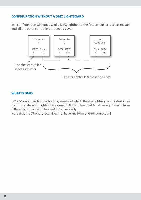
CONFIGURATION WITHOUT A DMX LIGHTBOARD
In a configuration without use of a DMX lightboard the first controller is set as master and all the other controllers are set as slave.
The first controller is set as master All other controllers are set as slave
WHAT IS DMX?
DMX 512 is a standard protocol by means of which theatre lighting control desks can communicate with lighting equipment. It was designed to allow equipment from different companies to be used together easily. Note that the DMX protocol does not have any form of error correction!
Controller 1
DMX DMXin out
Controller 2
DMX DMXin out
Last Controller
DMX DMXin out

9
CONTROLLER MENU STRUCTURE
- - - - STATUS - - - -stand alone master
[select DMX mode]> DMX mode 24 DMX mode 10U/D=scroll select >
[select type]> set as master set as slaveU/D=scroll select >
[choose operat. mode]> stand alone DMX modeU/D=scroll select >
[set DMX base]001
U/D=modify confirm >
[parameter source]> set parameters recall a presetU/D=scroll select >
[select a preset]> user memory 1 user memory 2U/D=scroll select >
[parameter list]> pattern type pattern behaviourU/D=scroll select >
[modify parameter]chase speed057U/D=modify confirm >
[choose an action]> set other parameter store settingU/D=scroll select >
[choose a location]> user memory 1 user memory 2U/D=scroll select >
[EXIT]> discard changes save changesU/D=scroll select >

10
OPERATOR CONSOLE
The operator console consists of an LCD display and a keypad with five push buttons. This console is the physical interface that lets you access the menu structure. The menu structure lets you modify the parameters of the controller.Use the buttons (Up, Down, Left and Right) to scroll through the menu structure.The UP button lets you scroll up in the menu structure or increase a parameter.The DOWN button lets you scroll down or decrease a parameter.The LEFT button lets you go back in the menu structure.The RIGHT button lets you select or confirm a menu item.
HOW TO SE TUP THE CONTROLLER
Press the UP button and then the DOWN button to unlock the keypad.After unlocking the controller, [Choose operat. Mode] will appear.• Choose“Standalone”ifyoudon’twanttouseaDMXsource.• Choose“DMXmode”ifyouwanttouseaDMXsource.
If you choose “Stand alone”, [Select type] will appear. Choose whether you want to set the controller as “master” or as “slave”.
• Ifyouchoose“Setasmaster”,[Parametersource]willappear.Hereyoucansetalltheparameters of the controller.
- Select “Set parameters” if you want to set and modify the parameters. [Parameter list] will appear; select which parameter you want to modify. [Modify parameter] will appear; modify the parameter and confirm. [Choose an action] will appear; select if you want to set another parameter or want to store your settings. •Ifyouchoose“setotherparameter”,[Parameterlist]willappear. •Ifyouchoose“storesetting“,[Choosealocation]willappear. Select in which “user memory” you want to store your settings.
- Select “Recall a preset” if you want to use a previously saved “user memory”. [Select a preset] will appear, select a previously saved “user memory”. [Exit!] will appear. Choose if you want to “Discard” or “Save” your “changes”.
• Ifyouchoose“Setasslave”,[Exit!]willappear.Chooseifyouwantto“Discard” or “Save” your “changes”.

11
If you choose “DMX mode”, [Select DMX mode] will appear. Now you can choose in which DMX mode you want to set the controller.
• Select“DMXmode24”tocontrolthechannelsindividually.• Select“DMXmode10”tocontrolthebuildinpatternsofthemastercontroller.• Select“DMXmode10SYNC”tocontrolthebuildinpatternsofallthecontrollers in the control network and synchronize all the slave controllers with the master controller.
When you have selected a DMX mode, [Set DMX base] will appear. Here you can choose the DMX base address and confirm. (numbers 001 to 500)
After confirming the DMX base, [Exit!] will appear. Choose if you want to “Discard” or “Save” your “changes”.

12
CONTROLLER MODES
Stand Alone Mode - setting the parametersThis Mode is accessible via the menu structure as described on previous pages. By using the operator console of the controller, the desired effect can easily be programmed by setting the following parameters. The parameters need only be set on the master controller.
• PatternType: 1channel@maximumintensity 2channels@maximumintensity 3channels@maximumintensity 4channels@maximumintensity 5channels@maximumintensity 6channels@maximumintensity 7channels@maximumintensity Strobe effect
• PatternBehaviour: softchase hard chase
• ChaseSpeed:000(minimumspeed)...255(maximumspeed)
• MinimumIntensity:000...255(SeealsoDMXmode10–fader4-MinimumIntensity)
• MaximumIntensity:000...255(SeealsoDMXmode10–fader5-MaximumIntensity)
• NumberofColours: 1colour 2 colours 3 colours 4 colours 4 colours rotating 3 colours rotating 2 colours rotating Chameleon!
• Colour1:000...255(SeeDMXmode10-Fader7to10-Selectionofcolour)
• Colour2:000...255(SeeDMXmode10-Fader7to10-Selectionofcolour)
• Colour3:000...255(SeeDMXmode10-Fader7to10-Selectionofcolour)
• Colour4:000...255(SeeDMXmode10-Fader7to10-Selectionofcolour)
Colours 1 to 4 are colour presets in which you can store a colour chosen from the colour pallet.

13
DMX Mode 10 – Controlling the build in patternsIf you have more than one controller, it is advisable to use DMX mode 10 SYNC. The channel descriptions of DMX Mode 10 have the same meaning as the parameters in the stand alone mode. Only the means of changing them are different. Instead of using the operator console, the channels (faders) of the DMX lightboard are used.
Fader 1 - Pattern Type
Fader 2 - Pattern Behaviour
With soft chase the lights will gradually fade in and out. With hard chase the lights will blink on and off.
Fader 3 - Chase Speed
Fader 4 - Minimum IntensityLimiter function sets the minimum intensity level. When set to a value higher than zero, the LEDs will not dim completely.
Fader 5 - Maximum IntensityLimiter function sets the maximum intensity level. When set to a value lower than 255, the LEDs will not burn at full capacity.Note that the maximum intensity has a higher priority than the minimum intensity!
DMX value Function Description0... 31 Chase Pattern 1 1channel@maximumintensity
32... 63 Chase Pattern 2 2channels@maximumintensity64... 91 Chase Pattern 3 3channels@maximumintensity
92... 127 Chase Pattern 4 4channels@maximumintensity128... 159 Chase Pattern 5 5channels@maximumintensity160... 191 Chase Pattern 6 6channels@maximumintensity192... 223 Chase Pattern 7 7channels@maximumintensity224... 255 Chase Pattern 8 Strobe effect
DMX value Description0... 127 Soft chase
128... 255 Hard chase
DMX value Description0 Minimum speed...
255 Maximum speed

14
Fader 6 - Number of colours
Fader 7 to 10 - Selection of colourChoose from the following colour pallet to set the 4 colour presets.
0 255
DMX value Description0.. 31 1 colour
32.. 63 2 colours64.. 95 3 colours
96.. 127 4 colours128.. 159 4 colours rotating160.. 191 3 colours rotating192.. 223 2 colours rotating224.. 255 Chameleon colour change
DMX value Description0 Blue
1.. 31 bluish white32 White
33.. 63 yellowish white64 Yellow
65.. 95 greenish yellow96 Green
97.. 127 greenish cyan128 Cyan
129.. 159 bluish cyan160 Blue
161.. 191 bluish magenta192 magenta
193.. 223 reddish magenta224 Red
225.. 254 orange255 yellow

15
1 2
3 4
5 6
7 8
9 10Colour 4
Colour 3
Colour 2
Colour 1
number of colours
Maximum Intensity
Minimum Intensity
Chase Speed
Pattern Behaviour
Pattern Type
GR
AP
HIC
AL
PR
ESEN
TATI
ON
OF
THE
DM
X C
HA
NN
EL A
RR
AN
GEM
ENT
sett
ing
as
byt
e va
lue
Ch
amel
eon
colo
urs
!
2 co
lou
rs
rota
teti
ng
3 co
lou
rs
rota
teti
ng
4 co
lou
rs
rota
teti
ng
4co
lou
r
3co
lou
rs
2co
lou
rs
1co
lou
rs
255 0

16
DMX Mode 24 - Controlling the channels individually
DMX channel
offset
Function
0 Red 1 Green LED channel 12 Blue 3 Red 4 Green LED channel 25 Blue 6 Red 7 Green LED channel 38 Blue 9 Red
10 Green LED channel 411 Blue 12 Red 13 Green LED channel 514 Blue 15 Red 16 Green LED channel 617 Blue 18 Red 19 Green LED channel 720 Blue 21 Red 22 Green LED channel 823 Blue
E.g.: When the DMX base address is set to 171 the red colour of LED channel 1 will appear on DMX channel 171 and the blue colour of LED channel 8 will appear on DMX channel 194.

17
FAQ’S
1. What is the maximum length of the cable between the controller and theconnector box of the application? You can determine the maximum length of the cable by using the following table:
Number of LEDs
96 128 192 256
Wire Size (mm²)
0,75 34m 26m 17m 13m
1,0 45m 34m 23m 17m
1,5 68m 52m 34m 26m
2. How many DMX channels are required for controlling the ShowLEDcontroller?DMX mode 10 (SYNC) requires minimum 10 channels and DMX mode 24 requires minimum 24 channels. Note that if you want to address all the controllers separately in DMX mode 24, you will need 24 channels per controller in the control network. (e.g. 4 controllers require 96 DMX channels)
CONTACT INFORMATION & SUPPORT
• Visitthesupportsectionofourwebsiteatwww.showled.com. Here you will find up-to-date FAQ’s and Tips and Tricks.
• [email protected],wewillreplytoyouassoon as possible.
• PlaceacalltoShowLEDFZC Tel: +971 6 557 83 07 Office hours: Sunday through Thursday from 09.00 to 18.00. Fridays and Saturdays we are closed.
• NotethatweareintheGMT-zone+4hour. Here are some useful links to convert time zones: www.worldtimeserver.com •www.timezoneconverter.com•www.timeanddate.com
• Contactaddress ShowLEDFZC•P.O.Box:120888•WarehouseQ4-006•SharjahAirportFreeZone•Sharjah•UnitedArabEmirates

18
TECHNICAL SPECIFICATIONS
Input - Supply voltage: 90 .. 250 Vac - Line frequency: 50 .. 60 Hz -Inputcurrent:2.2A(@115Vac)/1.2A(@230Vac) - Input power: 225 Watt - Fuses, medium delay, 4A, 20x5mm - Mains input: standardized IEC power inlet - PFC (Power Factor Correction) circuit present
Outputs ( 4 XLRs in total) - Output Voltage: 24 V - Total Output Power: 200 Watt
Data Ports - DMX input (5 pole male XLR) - DMX output (5 pole female XLR)
Environmental - Operating temperature, humidity*: 0°C .. +50°C, < 80% RH - Storage temperature, humidity*: 0°C .. +50°C, < 60% RH (* non-condensing)
Mechanical - Dimensions: 215 x 213 x 55 mm - Weight: 2.05 kg

19
DECLARATION OF CONFORMITY (2nd edition)
We, ShowLED FZCP.O. Box : 120888 - Warehouse Q4-006 - Sharjah Airport Free Zone - Sharjah - UAEDeclare that the product
ShowLED Chameleon System²
is in conformity with the essential requirements of the following directives and standards:
Low Voltage Directive (73/23/EEC)
IEC 60065, 12-2005 (Edition 7.1) Audio, video and similar electronic apparatus – Safety requirements
EMC Directive (89/336/EEC and 92/31/EEC)
EN 55103-1, 11-1996 Electromagnetic compatibility for audio, video, audio-visual and entertainment lighting control apparatus for professional use. Part 1: EmissionEN 55103-2, 11-1996 Electromagnetic compatibility for audio, video, audio-visual and entertainment lighting control apparatus for professional use. Part 2: ImmunityEN 55022 Standards of radio disturbance of information technology equipment
Sharjah, United Arab Emirates Kenny Janssens, Managing Director
01/9/2011
(Date of issue) (Signature of authorised person)
2 See page 6 for an overview of the system

LED starcloths for:
theatresTV studiosconcerts
night clubsexhibitions
corporate eventsmovie theatres
cruise ships
Visit our website for further information or to check contact details of your local ShowLED supplier.
www.showled.com