controlled separation experimental...
TRANSCRIPT

iNEMI Confidential
for member organization use only
Controlled Separation
Experimental Results
iNEMI F2F Meeting
Mar 5, 2012

1 iNEMI Confidential
for member organization use only
Outline
•Objectives
•Description
•Results
•Summary

2 iNEMI Confidential
for member organization use only
Experiment Objectives
•Verify ability of multiple wavelength probe,
using existing test equipment, to measure the
mated connector separation gap
•Controlled separation to map RL and IL as
function of gap for multiple wavelengths over
initial several μm

3 iNEMI Confidential
for member organization use only
Experiment Description
•Test Procedure
•Parameters
•Equipment
•Setup at TE Connectivity
4 iNEMI Confidential
for member organization use only
Test Execution
• Pre-test
– Adjust gap using manual stages
– Power reading and magnifying glass as feedback for
“contact”
• Test
– LV program separates ferrules, collects and stores RL/IL data
– Monitor real-time displays for data quality
• Post-process
– Run post-process program to recall stored data and create
data graphs with theoretical overlay

5 iNEMI Confidential
for member organization use only
Parameters
•Range of motion was 2.5 μm and 4 μm
•Step size of 20 and 50 nm
•RL only measured
– Problems with IL data
• Appeared to be single wavelength (1310)
– Speed up measurement

6 iNEMI Confidential
for member organization use only
Equipment
•OptoTest 930; Return & Insertion Loss
– λ±30nm, RL ±1 dB
•PI Piezo Stage Model P-752.21C
– 0-30 μm range, 0.2 nm resolution
– Open Loop control via NI DIO board
•Manual XYZ; ~500 nm resolution
•Custom fixture to hold ferrules
•Custom LabVIEW code to control motion and
read OptoTest RL/IL meter

7 iNEMI Confidential
for member organization use only
Fixture Details
• Two bare ferrule SC
connectors held as shown at
right (Alignment sleeve NOT
used)
Piezo stage
Programmed Moves
Manual XYZ stage
Coarse Align

8 iNEMI Confidential
for member organization use only
Setup at TE Connectivity
Shane uses
magnifying glass
to verify nominal
contact

9 iNEMI Confidential
for member organization use only
Results

10 iNEMI Confidential
for member organization use only
Results Summary
•Two RL data sets collected
•RL minimum was limited at 10-11 dB by
instrument
•Data was not limited by instrument’s max RL
of 80dB
11 iNEMI Confidential
for member organization use only
Full Contact Test Results
• Measured RL > 65 dB
• Matched theory after iterative adjustments
– Gap offset, RL offset, Actual wavelengths
• Tight match in critical 50-200 nm region
• Departure from theory below 50 nm was likley due to
connector XY misalignment once full contact was
made (fixture issue)

12 iNEMI Confidential
for member organization use only
Data for all λ’s; 20 nm Step

13 iNEMI Confidential
for member organization use only
Data and Theory for all λ’s
Ideal is solid line
Data is symbol only

14 iNEMI Confidential
for member organization use only
λ:1310,1490 nm; 50 nm Step
Ideal is solid line
Data is symbol only

15 iNEMI Confidential
for member organization use only
λ:1550,1625 nm; 50 nm Step
Ideal is solid line
Data is symbol only

16 iNEMI Confidential
for member organization use only
Method for Determining Corrections
• Found X offset (nominal) that aligned all peaks
• Varying offsets by λ/2 of 1310 nm had one or
more λ’s with gross misalignment
• Both manual and later automatic LMS error
optimization of match between data and theory
used to fine tune X offset
• RL offset was applied to nominally minimize
error in 50-200 nm separation range
17 iNEMI Confidential
for member organization use only
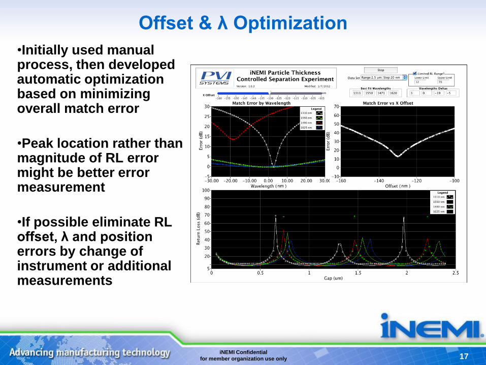
Offset & λ Optimization
•Initially used manual process, then developed automatic optimization based on minimizing overall match error
•Peak location rather than magnitude of RL error might be better error measurement
•If possible eliminate RL offset, λ and position errors by change of instrument or additional measurements

18 iNEMI Confidential
for member organization use only
Return Loss from 0-200nm
Uncorrected
Corrected
• Order of
wavelengths in
RL value is same
with or without
correction
• Correction
required to
improve match
is at most 0.5
dB, well within
the ±1 dB
accuracy spec
λ (nm) 1310 1550 1490 1625
Offset (dB) 0.15 -0.5 0.15 -0.5
RL offsets applied to minimize error
Ideal is solid line
Data is symbol only

19 iNEMI Confidential
for member organization use only
RL Error from 0-200nm
Uncorrected RL Offsets Corrected RL Offsets

20 iNEMI Confidential
for member organization use only 2
0
• Actual wavelengths used for final theoretical
calculations:
• Variation from nominal were well within ±30nm
spec for the OptoTest 930
Estimated Wavelengths
Actual Wavelengths Delta Wavelengths
Nominal Step 50
nm Step 20 nm Zero Offset
Step 50 nm
Step 20 nm Zero Offset
1310 1310 1302 0 3
1550 1548 1539 -2 0
1490 1478 1465 -12 -18
1625 1618 1605 -7 -5

21 iNEMI Confidential
for member organization use only 2
1
Data Adjustments
•Measured data position was adjusted by a
fixed, positive offset
•Wavelengths used for calculated RL adjusted
to optimize peak matches
•RL offset for each pair of wavelengths
selected after other adjustments made in
order to line data up in 50-200 nm region

22 iNEMI Confidential
for member organization use only 2
2
Ambiguity Regions
• The ideal curves unambiguously resolve position over the range of interest for the four wavelengths used
• Meter’s inability to measure RL below 10 dB produces gap regions were 2,3 or all of the wavelengths are clipped
• Ambiguity holes are 100-400 nm wide
• More study required to develop gap mapping which includes this effect

23 iNEMI Confidential
for member organization use only 2
3
Experiment Improvements
• Use more accurate (in RL and λ) instrument
– Different meter or in-situ calibration methods
• Drive the existing piezo stage to get initial contact,
along with load cell
• Improve fixture to hold ferrules more accurately,
eliminate concerns about XY slippage on contact
24 iNEMI Confidential
for member organization use only 2
4
Summary
• Controlled separation experiment was
successfully conducted
• Demonstrated that multiple wavelength
interrogation technique may be used to probe
the separation distance in a mated connector
• Ability to measure low values of return loss,
greater wavelength accuracy and reduced RL
offsets required to accurately measure
contaminated connector in-situ gap

25 iNEMI Confidential
for member organization use only 2
5
Experiment Participants
• Doug Wilson, Brian Bystrek of PVI Systems
• Dave Fisher and Shane Nipple of TE Connectivity
• Brian developed the LV code and integrated the
hardware
• Shane and Brian operated the equipment, ensuring high
quality data collection

iNEMI Confidential
for member organization use only
www.inemi.org Email contacts:
Bill Bader [email protected]
Bob Pfahl [email protected]