controlled rotation sewer nozzle user …€¦ · whr magnum series controlled rotation sewer...
TRANSCRIPT

whr magnum series CONTROLLED ROTATION
SEWER NOZZLE USER MANUAL
PL 604 REV C (05/2018)
2 866-795-1586 • WWW.SEWERNOZZLES.COM
TABLE OF CONTENTS
MANUFACTURER’S INFORMATION . . . . . . . . . . . . . . . . . . . . . . . . . . . . . . . . . . . . . . . . . . . . . . . . . . . . . . . . . . . 3
SPECIFICATIONS. . . . . . . . . . . . . . . . . . . . . . . . . . . . . . . . . . . . . . . . . . . . . . . . . . . . . . . . . . . . . . . . . . . . . . . . . . 3
DESCRIPTION OF EQUIPMENT AND INTENDED USE . . . . . . . . . . . . . . . . . . . . . . . . . . . . . . . . . . . . 3
KEY FEATURES . . . . . . . . . . . . . . . . . . . . . . . . . . . . . . . . . . . . . . . . . . . . . . . . . . . . . . . . . . . . . . . . . . . . . . . . . . . 3
TOOL OVERVIEW . . . . . . . . . . . . . . . . . . . . . . . . . . . . . . . . . . . . . . . . . . . . . . . . . . . . . . . . . . . . . . . . . . . . . . . . . . . . . . 4
WARNING AND SAFETY INSTRUCTIONS . . . . . . . . . . . . . . . . . . . . . . . . . . . . . . . . . . . . . . . . . . . . . . . . . . . . . 5
OPERATION . . . . . . . . . . . . . . . . . . . . . . . . . . . . . . . . . . . . . . . . . . . . . . . . . . . . . . . . . . . . . . . . . . . . . . . . . . . . . . . . . . . . 6
TROUBLESHOOTING . . . . . . . . . . . . . . . . . . . . . . . . . . . . . . . . . . . . . . . . . . . . . . . . . . . . . . . . . . . . . . . . . . . . . . . . . . 7
HEAD REMOVAL AND REPLACEMENT . . . . . . . . . . . . . . . . . . . . . . . . . . . . . . . . . . . . . . . . . . . . . . . . . . . . . . . 9
FLUID REPLACEMENT . . . . . . . . . . . . . . . . . . . . . . . . . . . . . . . . . . . . . . . . . . . . . . . . . . . . . . . . . . . . . . . . . . . . . . . . . 10
DISASSEMBLY . . . . . . . . . . . . . . . . . . . . . . . . . . . . . . . . . . . . . . . . . . . . . . . . . . . . . . . . . . . . . . . . . . . . . . . . . . . . . . . . . 11
ASSEMBLY . . . . . . . . . . . . . . . . . . . . . . . . . . . . . . . . . . . . . . . . . . . . . . . . . . . . . . . . . . . . . . . . . . . . . . . . . . . . . . . . . . . . . 14
PART NAMES/NUMBERS AND SERVICE KITS . . . . . . . . . . . . . . . . . . . . . . . . . . . . . . . . . . . . . . . . . . . . . . . . 18
TERMS AND CONDITIONS AND WARRANTY . . . . . . . . . . . . . . . . . . . . . . . . . . . . . . . . . . . . . . . . . . . . . . . . . 20

3866-795-1586 • WWW.SEWERNOZZLES.COM
MANUFACTURER’S INFORMATION
SPECIFICATIONS
Tool Family: Warthog Magnum
Tool Model: WHR-1/2, WHR-3/4
Pipe Size: 6-18 in. (152-457 mm)
Pressure Range: 1500-8000 psi (100-550 bar)
Flow Range: 14-50 GPM (60-90 l/min)
Flow Rating: 3 Cv
Rotation Speed: 150-400rpm
Pulling Force: 30 to 90 lbs (13 to 41 kg)
Inlet Connection: 1/2” NPT or BSPP, 3/4” NPT or BSPP
Nozzle Ports: 5 x 1/8” NPT
Outside Diameter: 3.625 in. 92 mm
Overall Length: 7.25 in. 184 mm
Weight: 6.75 lbs 3 kg
StoneAge Inc.
466 S. Skylane Drive
Durango, CO 81303, USA
Phone: 970-259-2869
Toll Free: 866-795-1586
www.stoneagetools.com
StoneAge Europe
Unit 2, Britannia Business Centre
Britannia Way
Malvern WR14 1GZ
United Kingdom
Phone: +44 (0) 1684 892065
DESCRIPTION OF EQUIPMENT AND INTENDED USE
The Warthog WHR Magnum is designed for mid-size pipes and lines, with the proven power and durability of the Magnum line of sewer tools
KEY FEATURES:
• Optimized speed control extends maintenance intervals
• Streamlined design prevents tool from catching inside of piped.
• Replaceable fins made of hardened steel for longer life available in different sizes.
• Flush style head protects front shaft seals for extended fluid life.
• Easily convertible from pulling to descaling
• Descaling ports now come standard.
• Latest seal technology effectively handles dirty or recycled water for improved performance
• Choose your rotation speed with 3 viscous fluid options.
This manual must be used in accordance with all applicable national laws. The manual shall be regarded as a part of the machine and shall be kept for reference until the final dismantling of the machine, as defined by applicable national law(s).
Updated manuals can be downloaded at: https://www.stoneagetools.com/manuals
4 866-795-1586 • WWW.SEWERNOZZLES.COM
WHR
TOOL OVERVIEW
DESCRIPTION
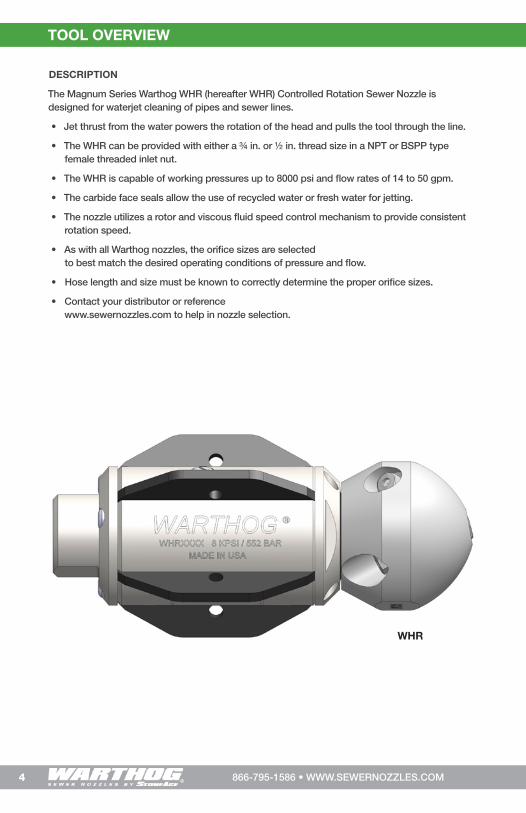
The Magnum Series Warthog WHR (hereafter WHR) Controlled Rotation Sewer Nozzle is designed for waterjet cleaning of pipes and sewer lines.
• Jet thrust from the water powers the rotation of the head and pulls the tool through the line.
• The WHR can be provided with either a ¾ in. or ½ in. thread size in a NPT or BSPP type female threaded inlet nut.
• The WHR is capable of working pressures up to 8000 psi and flow rates of 14 to 50 gpm.
• The carbide face seals allow the use of recycled water or fresh water for jetting.
• The nozzle utilizes a rotor and viscous fluid speed control mechanism to provide consistent rotation speed.
• As with all Warthog nozzles, the orifice sizes are selected to best match the desired operating conditions of pressure and flow.
• Hose length and size must be known to correctly determine the proper orifice sizes.
• Contact your distributor or reference www.sewernozzles.com to help in nozzle selection.
5866-795-1586 • WWW.SEWERNOZZLES.COM
WARNING AND SAFETY INSTRUCTIONS
WARNING Operations with this equipment can be potentially hazardous. Caution must be exercised prior to and during machine and water jet tool use. Please read and follow all of these instructions, in addition to the guidelines in the WJTA Recommended Practices handbook, available online at www.wjta.org. Deviating from safety instructions and recommended practices can lead to severe injury and/or death.
• Do not exceed the maximum operating pressure specified for any component in a system. The immediate work area must be marked off to keep out untrained persons.
• Inspect the equipment for visible signs of deterioration, damage, and improper assembly. Do not operate until repaired. Make sure all threaded connections are tight and free of leaks.
• All operators and persons in close proximity must wear personal protective equipment, including approved protection for body, hands, feet, face, ears, eyes, and air passages. Please refer to the WJTA Recommended Practices, Section 6.
• Inspect the high pressure hose for damage. Only high quality hoses intended for waterblast
applications should be used.
6 866-795-1586 • WWW.SEWERNOZZLES.COM
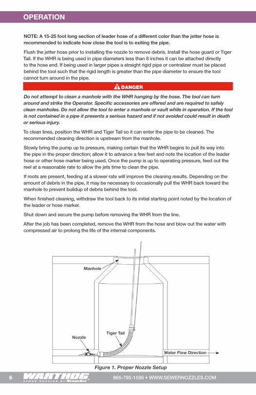
NOTE: A 15-25 foot long section of leader hose of a different color than the jetter hose is recommended to indicate how close the tool is to exiting the pipe.
Flush the jetter hose prior to installing the nozzle to remove debris. Install the hose guard or Tiger Tail. If the WHR is being used in pipe diameters less than 8 inches it can be attached directly to the hose end. If being used in larger pipes a straight rigid pipe or centralizer must be placed behind the tool such that the rigid length is greater than the pipe diameter to ensure the tool cannot turn around in the pipe.
DANGER
Do not attempt to clean a manhole with the WHR hanging by the hose. The tool can turn around and strike the Operator. Specific accessories are offered and are required to safely clean manholes. Do not allow the tool to enter a manhole or vault while in operation. If the tool is not contained in a pipe it presents a serious hazard and if not avoided could result in death or serious injury.
To clean lines, position the WHR and Tiger Tail so it can enter the pipe to be cleaned. The recommended cleaning direction is upstream from the manhole.
Slowly bring the pump up to pressure, making certain that the WHR begins to pull its way into the pipe in the proper direction; allow it to advance a few feet and note the location of the leader hose or other hose marker being used. Once the pump is up to operating pressure, feed out the reel at a reasonable rate to allow the jets time to clean the pipe.
If roots are present, feeding at a slower rate will improve the cleaning results. Depending on the amount of debris in the pipe, it may be necessary to occasionally pull the WHR back toward the manhole to prevent buildup of debris behind the tool.
When finished cleaning, withdraw the tool back to its initial starting point noted by the location of the leader or hose marker.
Shut down and secure the pump before removing the WHR from the line.
After the job has been completed, remove the WHR from the hose and blow out the water with compressed air to prolong the life of the internal components.
OPERATION
NozzleTiger Tail
Figure 1. Proper Nozzle Setup
Water Flow Direction
Manhole

7866-795-1586 • WWW.SEWERNOZZLES.COM
TROUBLESHOOTING
HEAD WILL NOT ROTATE: • Check to see if any jets, or inserts, are plugged. Even if a jet is only partially blocked it can
keep the head from rotating. Jets must be removed from the head to be properly cleaned. Poking the material plugging the jet back into the head will not fix the problem because it will re-plug the jet once water starts flowing. If the jets are all clear, wash the nozzle off with water to remove any debris or grit between the head, body and shaft. Then try rotating head by hand. It should feel free with a slight amount of smooth resistance. If it feels rough, gritty, or hard to turn, the tool needs to be repaired. It may need new bearings and shaft seals or high pressure seals. It is possible the tool needs viscous fluid added or changed, but if viscous fluid is confirmed to be present, a rebuild should be considered.
HEAD SPINS TOO FAST: • If the nozzle is spinning significantly faster than normal, or if the nozzle starts to sound
different (like a jet engine or a turbo charger) the nozzle may be low on viscous fluid, or the viscous fluid may be contaminated. In this case, add or change the fluid as appropriate. Continued operation in this state can mechanically damage the tool and a rebuild may be required to replace the faulty shaft seals.
HIGH-PRESSURE WATER SEALS LEAK: • The WHR’s seal design uses a slight amount of water for lubrication. At full pressure it
should not leak more than a few drops with a new set of seals. The high pressure seals may need to be replaced if you are not able to get to full pressure or when a continuous spray comes from under the WHR 020 Back Plate.
LOCK-UP TROUBLESHOOTING TIP: • Rotate in reverse 1 1/4 to 1 1/2 turns to unlock braking mechanism. If tool rotates smoothly
then redress may not be required.• If the head rotates freely by hand, check the jet sizes and calculate pressure loss through
the coil tubing and check with your distributor or StoneAge® to make certain there is enough jet torque to provide rotation.
• Verify jetting at http://jetting.stoneagetools.com/#/, contact your factory authorized Warthog® dealer or contact StoneAge®, Inc.

8 866-795-1586 • WWW.SEWERNOZZLES.COM
LIST OF TOOLS:
• Bench Vice (recommended)• Arbor Press (recommended)• Smooth Jaw Adjustable Wrench (such as
Crescent® C718 Automotive Wrench)• Large Adjustable Wrench (such as a 12”
Crescent® Wrench) • Medium size flat-head screw driver• Pick• Bearing Splitter• 3/8 Drive Ratchet with 3” Extension
• WHR 612 Tool Kit (Includes)BA 481 Bearing Removal ToolWGR 180 T-25 L-WrenchWGR 186 HP Seal PullerWHR 181 Removal Press TubeWHR 182 Installation Press TubeWHR 183 Hex ToolWHR 184 HP Seal Press
WHR 187 HP Seal Puller Pin
LIST OF MATERIALS:
• Clean lint free rags or blue shop towels• Anti-Seize - StoneAge PN
(GP 043 Blue Goop)• Lithium Soap Grease – StoneAge PN
(GP 048 Grease)• Blue Loctite® 242• Isopropyl Alcohol or Denatured Alcohol
HEAD REMOVAL/REPLACEMENT
***Product training and proper tools are required to service this nozzle. If you are uncomfortable performing the service, bring the nozzle to your authorized dealer.*
The use of a bench vice and an arbor press is highly helpful. Take care throughout the entire procedure to keep the internals clean and free from grit, lint, and contamination. Failure to do so could result in premature failure after service.
The WHR head is easily removed. Different heads can be configured to match specific jobs. Changing heads is a quick way to get optimal performance for every job type - from flushing lines to removing grease and roots. The shaft and head utilize an O-Ring and straight thread connection, eliminating the need for Teflon Tape.
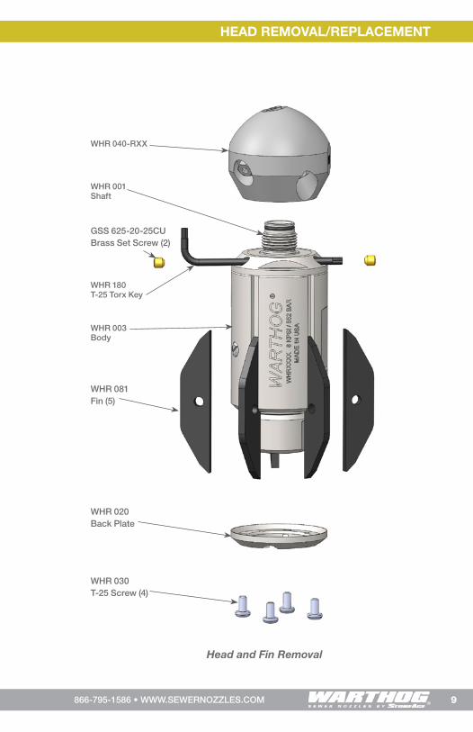
Remove the head. Remove the two Set Screws (GSS 625-20-25CU) using a 1/8 hex key. Insert the provided L-Wench (WGR 180) through the hole in the Front Nut (WHR 004) in order to lock the shaft. The L-Wrench should stick out the opposite side. Rotating the Head may be required to align the through hole and the shaft. Loosen and remove the Head. The use of a bench vice may aid in this process. DO NOT loosen the Head using the Centralizer Fins (WHR 081) or Body (WHR 003) as tool damage may occur.
Install the Head. Before reinstalling the head, make sure the threads on the shaft and in the head are free from grit, debris, and old Loctite®. Make sure the O-Ring on the shaft is clean and in good condition. Apply grease to the bore in the head where the O-Ring seats. Apply Loctite® Threadlocker Blue 242® to one full thread in both the Shaft and the Head. Torque to 50 ft-lb.
Fin Removal and Replacement. The Centralizer Fins are replaceable without opening the internals of the nozzle. Remove the four Screws (WHR 030) at the rear of the tool using the provided L-Wrench (WGR 180). The Back Plate (WHR 020) and Fins (WHR 081) can then be removed. Pull the fins rearward and outward. When reinstalling new fins, make sure the front pocket and the groove is free from debris. Replace the Back Plate, apply Loctite® Threadlocker Blue 242® to the Screws, and then tighten the Screws evenly in a cross pattern. Tighten Screws to 20 in-lb.
HEAD REMOVAL/REPLACEMENT
9866-795-1586 • WWW.SEWERNOZZLES.COM
HEAD REMOVAL/REPLACEMENT
WHR 180 T-25 Torx Key
WHR 040-RXX
WHR 030T-25 Screw (4)
WHR 020Back Plate
WHR 003 Body
WHR 001 Shaft
WHR 081 Fin (5)
GSS 625-20-25CUBrass Set Screw (2)
Head and Fin Removal
10 866-795-1586 • WWW.SEWERNOZZLES.COM
SPEED CONTROL FLUID CHANGE
The speed control fluid changing is made easy with the WHR and disassembly of the tool is not required. This means there is less chance for contamination and longer overall tool life. Fluid changes should only be performed by qualified persons.
NOTE: Improper fluid change maintenance can result in reduced bearing or shaft seal life. DO NOT PRESSURIZE THE WHR BODY by forcing new fluid in too fast. The fluid is thick and only very light pressure should be applied to the syringe. Excess pressure will force fluid past the inner shaft seals and into the bearings. Use extreme care when performing this procedure.
The WHR is designed for maximum viscous fluid life and frequent fluid changes should not be required. A fluid change should be performed when replacing bearings and shaft seals.
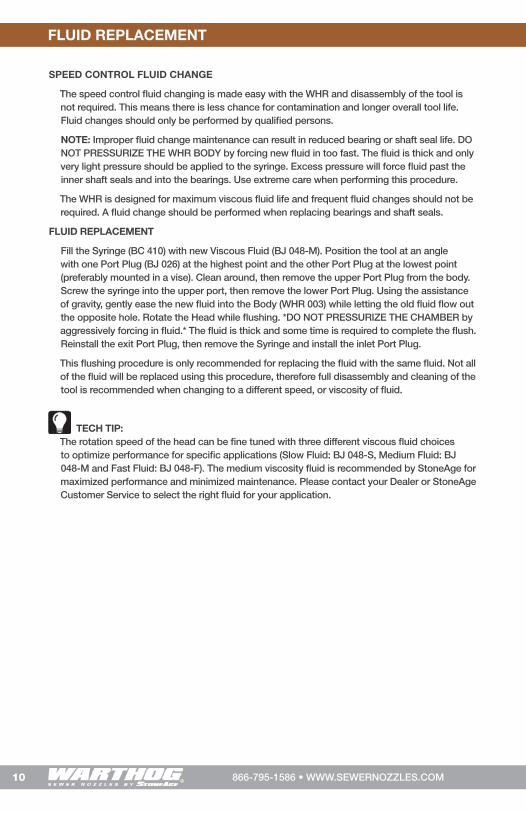
FLUID REPLACEMENT
Fill the Syringe (BC 410) with new Viscous Fluid (BJ 048-M). Position the tool at an angle with one Port Plug (BJ 026) at the highest point and the other Port Plug at the lowest point (preferably mounted in a vise). Clean around, then remove the upper Port Plug from the body. Screw the syringe into the upper port, then remove the lower Port Plug. Using the assistance of gravity, gently ease the new fluid into the Body (WHR 003) while letting the old fluid flow out the opposite hole. Rotate the Head while flushing. *DO NOT PRESSURIZE THE CHAMBER by aggressively forcing in fluid.* The fluid is thick and some time is required to complete the flush. Reinstall the exit Port Plug, then remove the Syringe and install the inlet Port Plug.
This flushing procedure is only recommended for replacing the fluid with the same fluid. Not all of the fluid will be replaced using this procedure, therefore full disassembly and cleaning of the tool is recommended when changing to a different speed, or viscosity of fluid.
TECH TIP: The rotation speed of the head can be fine tuned with three different viscous fluid choices to optimize performance for specific applications (Slow Fluid: BJ 048-S, Medium Fluid: BJ 048-M and Fast Fluid: BJ 048-F). The medium viscosity fluid is recommended by StoneAge for maximized performance and minimized maintenance. Please contact your Dealer or StoneAge Customer Service to select the right fluid for your application.
FLUID REPLACEMENT
11866-795-1586 • WWW.SEWERNOZZLES.COM
DISASSEMBLY
WS 210O-Ring
WHR 003 Body
3
5
4
5
WHR 040-RXXHead
2
1
DISASSEMBLY
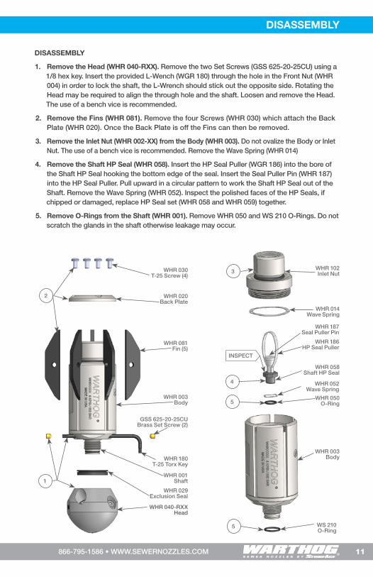
1. Remove the Head (WHR 040-RXX). Remove the two Set Screws (GSS 625-20-25CU) using a 1/8 hex key. Insert the provided L-Wench (WGR 180) through the hole in the Front Nut (WHR 004) in order to lock the shaft, the L-Wrench should stick out the opposite side. Rotating the Head may be required to align the through hole and the shaft. Loosen and remove the Head. The use of a bench vice is recommended.
2. Remove the Fins (WHR 081). Remove the four Screws (WHR 030) which attach the Back Plate (WHR 020). Once the Back Plate is off the Fins can then be removed.
3. Remove the Inlet Nut (WHR 002-XX) from the Body (WHR 003). Do not ovalize the Body or Inlet Nut. The use of a bench vice is recommended. Remove the Wave Spring (WHR 014)
4. Remove the Shaft HP Seal (WHR 058). Insert the HP Seal Puller (WGR 186) into the bore of the Shaft HP Seal hooking the bottom edge of the seal. Insert the Seal Puller Pin (WHR 187) into the HP Seal Puller. Pull upward in a circular pattern to work the Shaft HP Seal out of the Shaft. Remove the Wave Spring (WHR 052). Inspect the polished faces of the HP Seals, if chipped or damaged, replace HP Seal set (WHR 058 and WHR 059) together.
5. Remove O-Rings from the Shaft (WHR 001). Remove WHR 050 and WS 210 O-Rings. Do not scratch the glands in the shaft otherwise leakage may occur.
WHR 081Fin (5)
WHR 186 HP Seal Puller
WHR 058 Shaft HP Seal
WHR 052Wave Spring
WHR 050 O-Ring
WHR 187 Seal Puller Pin
WHR 003 Body
WHR 001 Shaft
WHR 029 Exclusion Seal
WHR 020Back Plate
WHR 102Inlet Nut
WHR 014Wave Spring
WHR 030T-25 Screw (4)
WHR 180T-25 Torx Key
GSS 625-20-25CUBrass Set Screw (2)
INSPECT
12 866-795-1586 • WWW.SEWERNOZZLES.COM
DISASSEMBLY
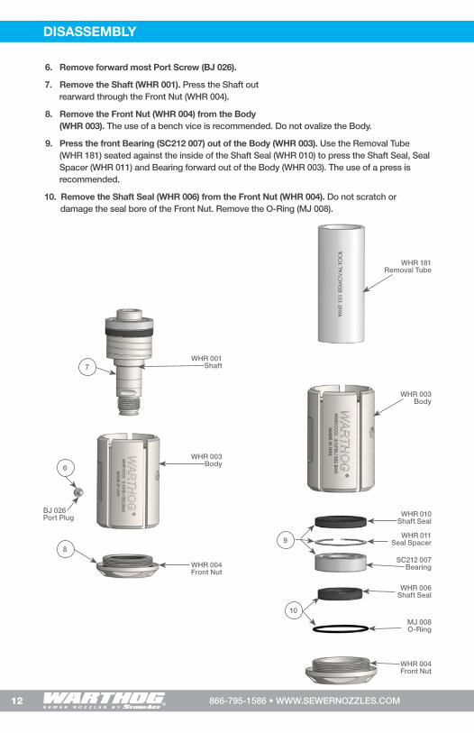
6. Remove forward most Port Screw (BJ 026).
7. Remove the Shaft (WHR 001). Press the Shaft out rearward through the Front Nut (WHR 004).
8. Remove the Front Nut (WHR 004) from the Body (WHR 003). The use of a bench vice is recommended. Do not ovalize the Body.
9. Press the front Bearing (SC212 007) out of the Body (WHR 003). Use the Removal Tube (WHR 181) seated against the inside of the Shaft Seal (WHR 010) to press the Shaft Seal, Seal Spacer (WHR 011) and Bearing forward out of the Body (WHR 003). The use of a press is recommended.
10. Remove the Shaft Seal (WHR 006) from the Front Nut (WHR 004). Do not scratch or damage the seal bore of the Front Nut. Remove the O-Ring (MJ 008).
WHR 003 Body
WHR 003 Body
WHR 001 Shaft
6
8
7
WHR 006 Shaft Seal
MJ 008 O-Ring
WHR 004 Front Nut
WHR 004 Front Nut
10
WHR 181 Removal Tube
SC212 007 Bearing
WHR 010 Shaft Seal
WHR 011 Seal Spacer
BJ 026Port Plug
9

13866-795-1586 • WWW.SEWERNOZZLES.COM
DISASSEMBLY
11. Remove the rear Bearing (WHR 009). Evenly seat the Bearing Removal Tool (BA 481) under the Rear Bearing then press on the end of the Shaft (WHR 001) to remove the Bearing. The Seal Spacer (WHR 011) and Shaft Seal (WHR 010) will then slip off the shaft. The use of a press is recommended.
12. Inspect the Shaft (WHR 001). Inspect for grooving where the four shaft seals ride. Inspect where the bearings ride for signs of slipping or scratches which extend into the seal area. Inspect the front shaft lock grooves for interfering deformation. Remove burrs or high spots by gently grinding or filing. If severely damaged or worn, the shaft may need to be replaced.
13. Remove the Nut HP Seal (WHR 058). Insert the HP Seal Puller (WGR 186) into the bore of the Nut HP Seal hooking the bottom edge of the seal. Insert the Seal Puller Pin (WHR 187) into the HP Seal Puller. Pull upward in a circular pattern to work the Seal out of the Shaft. Remove the Wave Spring (WHR 052). Inspect the polished faces of the HP Seals, if chipped or damaged, replace HP Seal set (WHR 058 and WHR 059).
14. Remove the Shaft Seal (WHR 006) from the Inlet Nut (WHR 002-XX). Do not scratch or damage the seal bore of the Inlet Nut.
15. Remove O-Rings from the Inlet Nut (WHR 002-XX). Remove WHR 076, MJ 008 and WHR 050. Do not scratch the glands in the Inlet Nut otherwise leakage may occur.
14
15
15
WHR 006 Shaft Seal
MJ 008 O-Ring
WHR 050O-Ring
WHR 076O-Ring
WHR 102 Inlet Nut
WHR 009 Bearing
WHR 001 Shaft
12. INSPECT
12. INSPECT
12. INSPECT
12. INSPECT
11
WHR 010 Shaft Seal
WHR 011 Seal Spacer
INSPECT
WHR 186 HP Seal Puller
WHR 052 Wave Spring
WHR 059-M90 Nut HP Seal
13
WHR 102 Inlet Nut
WHR 187 Seal Puller Pin
14 866-795-1586 • WWW.SEWERNOZZLES.COM
ASSEMBLY ASSEMBLY
ASSEMBLY
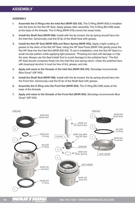
1. Assemble the O-Rings into the Inlet Nut (WHR 002-XX). The O-Ring (WHR 050) is installed into the bore for the Nut HP Seal. Apply grease after assembly. The O-Ring (MJ 008) seats at the base of the threads. The O-Ring (WHR 076) covers the weep holes.
2. Install the Shaft Seal (WHR 006). Install with the lip inward, the lip spring should face into the Inlet Nut. Generously coat the ID lip of the Shaft Seal with grease.
3. Install the Nut HP Seal (WHR 059) and Wave Spring (WHR 052). Apply a light coating of grease to the stem of the Nut HP Seal. Using the HP Seal Press (WHR 184) gently press the Nut HP Seal into the Inlet Nut (WHR 002-XX). To aid in installation, rock the Nut HP Seal in a small circular pattern while applying light pressure. *Pressing too hard will damage or chip the seal. Always use the Seal Install Tool to avoid damage to the polished face.* The Nut HP Seal should compress freely into the Inlet Nut and spring return. Clean the polished face with Isopropyl alcohol; it must be free of lint, grease, and oils.
4. Apply anti-seize to the threads of the Inlet Nut (WHR 002-XX). StoneAge recommends Blue Goop® (GP 043).
5. Install the Shaft Seal (WHR 006). Install with the lip inward, the lip spring should face into the Front Nut. Generously coat the ID lip of the Shaft Seal with grease.
6. Assemble the O-Ring onto the Front Nut (WHR 004). The O-Ring (MJ 008) seats at the base of the threads.
7. Apply anti-seize to the threads of the Front Nut (WHR 004). StoneAge recommends Blue Goop® (GP 043).
WHR 052 Wave Spring
WHR 184HP Seal Press
WHR 059-M90 Nut HP Seal
WHR 102 Inlet Nut
ANTI-SEIZE
GREASE
CLEAN
4
3
MJ 008 O-Ring
WHR 006Shaft Seal
WHR 050 O-Ring
WHR 076O-Ring
GREASE
WHR 102 Inlet Nut
2
1
1
WHR 006 Shaft Seal
MJ 008 O-Ring
WHR 004 Front Nut
ANTI-SEIZE
GREASE
5
6
7

15866-795-1586 • WWW.SEWERNOZZLES.COM
ASSEMBLY
8. Pack the front Bearing (SC212 007) with grease. StoneAge recommends Lithium Complex NLGI 1 Grease. Coat the ID, OD, and every surface of the Bearing with grease.
9. Install the front Bearing Stack. Use the Install Tube (WHR 182) to install the front Bearing (SC212 007), Seal Spacer (WHR 011), and Shaft Seal (WHR 010) into the Body (WHR 003). Install with the Shaft Seal lip inward; the lip spring should face in toward the center of the Body. Lightly coat the lip with grease. The use of a press is recommended.
10. Install the Port Screws (BJ 026).
11. Install the assembled Front Nut (WHR 004). Apply anti-seize to the threads. Torque to 100-120 ft-lbs.
12. Install the Shaft (WHR 001). Apply a very light coat of grease to the Shaft where the Shaft Seals and Bearings ride. Gently press the Shaft into the Body (WHR 003) by hand. The shoulder on the Shaft should stick out very slightly from the Front Nut.
13. Fill with Fluid (BJ 048-M). Fill the Body with fluid to the bottom of the chamfer of the shoulder on the Shaft. This fluid level height is critical.
14. Spin the Shaft (WHR 001) to bleed the Fluid (BJ 048-M). Attach the Hex Tool (WHR 183) to a 3/8 in. drive ratchet with a 3 in. extension and insert it into the internal hex in the end of the Shaft. Slowly spin the Shaft counter-clockwise to release all the air bubbles from the system.
WHR 004Front Nut
WHR 003 Body
11
WHR 182Install Tube
WHR 009 Bearing
WHR 011Seal Spacer
BJ 026Port Plug
WHR 010Shaft Seal
WHR 003 Body
8
9
10
WHR 001Shaft
WHR 183 Hex Tool
3/8 Drive Ratchet and
Extension
WHR 003 Body
14
13
12
FILL LINE

16 866-795-1586 • WWW.SEWERNOZZLES.COM
ASSEMBLY ASSEMBLY
15. Pack the rear Bearing (WHR 009) with grease. StoneAge recommends Lithium Complex NLGI 1 Grease. Coat the ID, OD, and every surface of the Bearing with grease.
16. Remove the rearward Port Screws (BJ 026).
17. Install the rear Bearing Stack. Use the Install Tube (WHR 182) to install the rear Bearing (WHR 009), Seal Spacer (WHR 011), and Shaft Seal (WHR 010) into the Body (WHR 003). Install with the Shaft Seal lip inward; the lip spring should face in toward the center of the Body. Lightly coat the lip with grease. As the stack is installed, fluid mixed with air will bleed out of the port in the side of the Body. The use of a press is recommended.
18. Install the rearward Port Screws (BJ 026).
19. Assemble the O-Rings into the Shaft (WHR 001). The O-Ring (WHR 050) is installed into the bore for the Shaft HP Seal. The O-Ring (WS 210) seats in the gland before the start of the threads. Grease both O-Rings after assembly.
20. Install the Shaft HP Seal (WHR 058). Place the Wave Spring (WHR 052) into the Inlet Nut (WHR 102). Apply a light coating of grease to the stem of the Nut HP Seal. Using the HP Seal Press (WHR 184) gently press the Nut HP Seal into the Inlet Nut. To aid in installation, rock the Nut HP Seal in a small circular pattern while applying light pressure may. *Pressing too hard will damage or chip the seal. Always use the Seal Install Tool to avoid damage to the polished face.* The Shaft HP Seal should compress freely into the Inlet Nut and spring return. Clean the polished face with Isopropyl alcohol; it must be free of lint, grease, and oils.
WHR 052 Wave Spring
WS 050 O-Ring
WS 210O-Ring
WHR 184HP Seal Press
WHR 058 Shaft HP Seal
GREASE
CLEAN
20
19
19
WHR 182Install Tube
WHR 009 Bearing
WHR 011Seal Spacer
BJ 026Port Plug
WHR 010Shaft Seal
WHR 003 Body
15
17
16
18
GREASE
GREASE

17866-795-1586 • WWW.SEWERNOZZLES.COM
ASSEMBLY
21. Install the Wave Spring (WHR 014).
22. Install the assembled Inlet Nut (WHR 002-XX). Apply anti-seize to the threads if not already done. Torque to 100-120 ft-lb.
23. Remove the Port Screw (BJ 026) to relieve any internal pressure. Hold the tool at an angle so one of the ports is the highest position, remove the Port Screw to relieve any pressure built up from installing the Inlet Nut (WHR 002-??) then reinstall the Port Screw.
24. Install the Head (WHR 040-RXX). Clean the threads of the Shaft and Head. Apply grease to the bore in the head where the O-Ring seats, then apply Loctite® Threadlocker Blue 242® to one full thread in each the Shaft and Head. Torque to 50 ft-lb.
25. Install the Brass Set Screws (GSS 625-20-25CU). Clean the threads, then apply Loctite® Threadlocker Blue 242® and install.
26. Install the Fins (WHR 081). Place the Fins into the slots in the Body (WHR 003). Install the Back Plate (WHR 020). Clean the threads of the six Screws (WHR 030) then apply Loctite® Threadlocker Blue 242®. Evenly tighten the Screws in a cross pattern. Torque to 20 in-lb.
23
21
22
WHR 102 Inlet Nut
WG 014Wave Spring
GREASE
WHR 180 T-25 Torx Key
WHR 030T-25 Screw
WHR 020Back Plate
WHR 003 Body
WHR 001 Shaft
WHR 081Fin (5)
WHR 040-RXXHead
26
24
BLUE LOCTITE® 242
BLUE LOCTITE® 242
GSS 625-20-25CUBrass Set Screw (2)
18 866-795-1586 • WWW.SEWERNOZZLES.COM
MAINTENANCE & OVERHAUL KITS
PART NAMES/NUMBERS AND SERVICE KITS
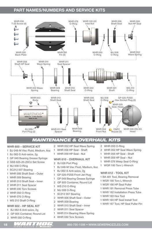
WHR 600 – SERVICE KIT1 BJ 048-M Visc Fluid, Medium, 6oz1 BJ 062-S Anti-seize, 2g1 GP 049 Bearing Grease Syringe 2 GSS 625-20-25CU Set Screw2 MJ 008 O-Ring 1 SC212 007 Bearing1 WHR 006 Shaft Seal – Outer1 WHR 009 Bearing2 WHR 010 Shaft Seal – Inner2 WHR 011 Seal Spacer4 WHR 030 Torx Screws2 WHR 050 O-Ring1 WHR 076 O-Ring1 WS 210 Shaft O-Ring
WHR 602 - HP SEAL KIT1 BJ 062-S Anti-seize, 2g2 GP 805 Container, Round Lid2 WHR 050 O-Ring
2 WHR 052 HP Seal Wave Spring1 WHR 058 HP Seal - Shaft1 WHR 059 HP Seal - Nut
WHR 610 - OVERHAUL KIT2 BJ 026 Port Plug1 BJ 048-M Visc Fluid, Medium, 6oz1 BJ 062-S Anti-seize, 2g1 GP 025-P2SS Front Jet Plug1 GP 049 Bearing Grease Syringe 2 GP 805 Container, Round Lid 1 WS 210 O-Ring2 MJ 008 O-Ring1 SC212 007 Bearing2 WHR 006 Shaft Seal – Outer2 WHR 009 Bearing2 WHR 010 Shaft Seal – Inner2 WHR 011 Seal Spacer1 WHR 014 Bearing Wave Spring4 WHR 030 Torx Screws
2 WHR 050 O-Ring2 WHR 052 HP Seal Wave Spring1 WHR 058 HP Seal - Shaft1 WHR 059 HP Seal – Nut1 WHR 076 Weep Seal O-Ring1 WGR 180 Torx L-Wrench
WHR 612 - TOOL KIT1 BA 481 Tool, Bearing Removal1 WGR 180 Torx L-Wrench1 WGR 186 HP Seal Puller1 WHR 181 Removal Press Tube1 WHR 182 Installation Press Tube1 WHR 183 Hex Tool1 WHR 184 HP Seal Install Tool1 WHR 187 Tool, HP Seal Puller Pin
WHR 040-DS-XXHead
WHR 030T-25 Screw (4)
WHR 020Back Plate
WHR 003 Body
WHR 001 Shaft
WHR 102-XX Inlet Nut
WS 210 O-Ring
WHR 050 O-Ring
WHR 076 O-Ring
WHR 010 Shaft Seal
WHR 010 Shaft Seal
WHR 006 Shaft Seal
WHR 006 Shaft Seal
MJ 008 O-Ring
MJ 008 O-Ring
WHR 050O-Ring
GP 025-P2SS Hex Socket Plug (2)
WHR 011 Seal Spacer
WHR 011 Seal Spacer
WHR 009 Bearing
WHR 009 Bearing
WHR 004 Front Nut
WHR 029 Seal, Head
WHR 014 Wave Spring
WHR 052 Wave Spring
WHR 052 Wave Spring
WHR 058Shaft HP Seal
WHR 059Nut HP Seal
WHR 081 Fin (5)
CNP2 Nozzle (5)
BJ 026 Port Plug (2)

19866-795-1586 • WWW.SEWERNOZZLES.COM
NOTES
This page is intentionally left blank.
20 866-795-1586 • WWW.SEWERNOZZLES.COM
TERMS AND CONDITIONS AND WARRANTY INFORMATION TERMS AND CONDITIONS AND WARRANTY INFORMATION
1. Acceptance of Terms and Conditions. Receipt
of these Terms and Conditions of Sale (“Terms and
Conditions”) shall operate as the acceptance by
StoneAge, Inc. (“Seller”) of the order submitted by
the purchaser (“Buyer”). Such acceptance is made
expressly conditional on assent by Buyer to these Terms
and Conditions. Such assent shall be deemed to have
been given unless written notice of objection to any of
these Terms and Conditions (including inconsistencies
between Buyer’s purchase order and this acceptance) is
given by Buyer to Seller promptly on receipt hereof.
Seller desires to provide Buyer with prompt and efficient
service. However, to individually negotiate the terms
of each sales contract would substantially impair
Seller’s ability to provide such service. Accordingly, the
product(s) furnished by Seller are sold only according
to the terms and conditions stated herein and with the
terms and conditions stated in any effective StoneAge
Dealer Agreement or StoneAge Reseller Agreement, if
applicable. Notwithstanding any terms and conditions
on Buyer’s order, Seller’s performance of any contract
is expressly made conditional on Buyer’s agreement
to these Terms and Conditions unless otherwise
specifically agreed to in writing by Seller. In the absence
of such agreement, commencement of performance,
shipment and/or delivery shall be for Buyer’s
convenience only and shall not be deemed or construed
to be an acceptance of Buyer’s terms and conditions.
2. Payment/Prices. Unless other arrangements have
been made in writing between Seller and Buyer, payment
for the product(s) shall be made upon receipt of invoice.
The prices shown on the face hereof are those currently
in effect. Prices invoiced shall be per pricelist in effect
at the time of shipment. Prices are subject to increase
for inclusion of any and all taxes which are applicable
and which arise from the sale, delivery or use of the
product(s), and the collection of which Seller is or may
be responsible to provide to any governmental authority,
unless acceptable exemption certificates are provided
by Buyer in accordance with applicable law. Buyer
shall pay all charges for transportation and delivery
and all excise, order, occupation, use or similar taxes,
duties, levies, charges or surcharges applicable to the
product(s) being purchased, whether now in effect
or hereafter imposed by any governmental authority,
foreign or domestic.
3. Warranty. SELLER MAKES NO WARRANTIES OR
REPRESENTATIONS AS TO THE PERFORMANCE
OF ANY PRODUCT EXCEPT AS SET FORTH IN THE
STONEAGE LIMITED WARRANTY PROVIDED WITH THE
PRODUCT.
4. Delivery. Seller is not obligated to make delivery by
a specified date, but will always use its best efforts to
make delivery within the time requested. The proposed
shipment date is an estimate. Seller will notify Buyer
promptly of any material delay and will specify the
revised delivery date as soon as practicable. UNDER
NO CIRCUMSTANCES SHALL SELLER HAVE ANY
LIABILITY WHATSOEVER FOR LOSS OF USE OR
FOR ANY DIRECT OR CONSEQUENTIAL DAMAGES
RESULTING FROM DELAY REGARDLESS OF THE
REASON(S).
All product(s) will be shipped F.O.B. point of origin,
unless specifically agreed otherwise, and Buyer shall
pay all shipping costs and insurance costs from that
point. Seller, in its sole discretion, will determine and
arrange the means and manner of transportation of the
product(s). Buyer shall bear all risk of loss commencing
with the shipment or distribution of the product(s) from
Seller’s warehouse. Order shortages or errors must be
reported within fifteen (15) business days from receipt of
shipment to secure adjustment. No product(s) may be
returned without securing written approval from Seller.
5. Modification. These Terms and Conditions are
intended by Seller and Buyer to constitute a final,
complete and exclusive expression of agreement
relating to the subject matter hereof and cannot be
supplemented or amended without Seller’s prior written
approval.
6. Omission. Seller’s waiver of any breach or Seller’s
failure to enforce any of these Terms and Conditions
at any time, shall not in any way affect, limit or waive
Seller’s right thereafter to enforce and compel strict
compliance with every term and condition hereof.
7. Severability. If any provision of these Terms and
Conditions is held to be invalid or unenforceable, such
invalidity or unenforceability shall not affect the validity
or enforceability of the other portions hereof.

21866-795-1586 • WWW.SEWERNOZZLES.COM
TERMS AND CONDITIONS AND WARRANTY INFORMATION
8. Disputes. Seller and Buyer shall attempt in good
faith to promptly resolve any dispute arising under
these Terms and Conditions by negotiations between
representatives who have authority to settle the
controversy. If unsuccessful, Seller and Buyer shall
further attempt in good faith to settle the dispute
by nonbinding third-party mediation, with fees and
expenses of such mediation apportioned equally to
each side. Any dispute not so resolved by negotiation
or mediation may then be submitted to a court of
competent jurisdiction in accordance with the terms
hereof. These procedures are the exclusive procedures
for the resolution of all such disputes between the Seller
and Buyer.
9. Governing Law. All sales, agreements for sale, offers
to sell, proposals, acknowledgments and contracts
of sale, including, but not limited to, purchase orders
accepted by Seller, shall be considered a contract under
the laws of the State of Colorado and the rights and
duties of all persons, and the construction and effect of
all provisions hereof shall be governed by and construed
according to the laws of such state.
10. Jurisdiction and Venue. Seller and Buyer agree
that the state or federal courts located within the City
and County of Denver, Colorado shall have sole and
exclusive jurisdiction over any litigation concerning any
dispute arising under these Terms and Conditions not
otherwise resolved pursuant to Section 9 as well as any
alleged defects of any Products or damages sustained
as a result of such alleged defects. Seller and Buyer
further agree that should any litigation be commenced
in connection with such a dispute, it shall only be
commenced in such courts. Seller and Buyer agree to
the exclusive jurisdiction of such courts and neither will
raise any objection to the jurisdiction and venue of such
courts, including as a result of inconvenience.
11. Attorney’s Fees. If any litigation is commenced
between Seller and Buyer, or their personal
representatives, concerning any provision hereof,
the party prevailing in the litigation shall be entitled,
in addition to such other relief that is granted, to a
reasonable sum as and for their attorneys’ fees and
costs in such litigation or mediation.
STONEAGE TRADEMARK LIST
View the list of StoneAge’s trademarks and service marks and learn how the trademarks should be used. Use of
StoneAge trademarks may be prohibited, unless expressly authorized.
http://www.StoneAgetools.com/trademark-list/
STONEAGE PATENT DATA
View the list of StoneAge’s current U.S. patent numbers and descriptions.
http://www.sapatents.com
STONEAGE TERMS AND WARRANTY
View StoneAge’s Terms and Warranty Conditions online.
http://www.stoneagetools.com/terms
http://www.stoneagetools.com/warranty

22 866-795-1586 • WWW.SEWERNOZZLES.COM
TERMS AND CONDITIONS AND WARRANTY INFORMATIONTERMS AND CONDITIONS AND WARRANTY INFORMATION
Warranties set forth herein extend only to End-Users,
meaning customers acquiring, or that have previously
acquired, a product manufactured by StoneAge
(“Product”) for their own use and not for resale, either
directly from StoneAge Inc. (“StoneAge”) or from a
StoneAge Authorized Dealer or Reseller (“Dealer”). No
warranty of any kind or nature is made by StoneAge
beyond those expressly stated herein.
1. LIMITED WARRANTY PERIOD. Subject to
the limitations and conditions hereinafter set forth,
StoneAge warrants its Product to be free from defects
in workmanship and material for a period of one (1) year
from the date of purchase by the End-User, provided that
the end of the limited warranty period shall not be later
than eighteen (18) months from the date of shipment of
the Product to the Dealer or the End-User by StoneAge
(“Limited Warranty Period”). All replacement parts which
are furnished under this Limited Warranty and properly
installed shall be warranted to the same extent as the
original Product under this Limited Warranty if, and only
if, the original parts were found to be defective within the
original Limited Warranty Period covering the original
Product. Replacement parts are warranted for the
remainder of the original Limited Warranty Period. This
Limited Warranty does not cover any component part of
any Product not manufactured by StoneAge. Any such
component part is subject exclusively to the component
manufacturer’s warranty terms and conditions.
2. LIMITED WARRANTY COVERAGE. StoneAge’s
sole obligation under this Limited Warranty shall be, at
StoneAge’s option and upon StoneAge’s inspection, to
repair, replace or issue a credit for any Product which is
determined by StoneAge to be defective in material or
workmanship. StoneAge reserves the right to examine
the alleged defective Product to determine whether this
Limited Warranty is applicable, and final determination
of limited warranty coverage lies solely with StoneAge.
No statement or recommendation made by a StoneAge
representative, Dealer or agent to End-User shall
constitute a warranty by StoneAge or a waiver or
modification to any of the provisions hereof or create any
liability for StoneAge.
3. WARRANTY SERVICE PROVIDERS. Service
and repair of the Product is to be performed only by
StoneAge authorized service representatives, including
Dealers who are authorized repair centers, with
StoneAge approved parts. Information about StoneAge
authorized service representatives can be obtained
through the StoneAge website at www.stoneagetools.
com/service. Unauthorized service, repair or
modification of the Product or use of parts not approved
by StoneAge will void this Limited Warranty. StoneAge
reserves the right to change or improve the material and
design of the Product at any time without notice to End-
User, and StoneAge is not obligated to make the same
improvements during warranty service to any Product
previously manufactured.
4. WARRANTY EXCLUSIONS. This Limited Warranty
does not cover, and StoneAge shall not be responsible
for the following, or damage caused by the following:
(1) any Product that has been altered or modified in any
way not approved by StoneAge in advance in writing;
(2) any Product that has been operated under more
severe conditions or beyond the rated capacity specified
for that Product; (3) depreciation or damage caused
by normal wear and tear, failure to follow operation or
installation instructions, misuse, negligence or lack
of proper protection during storage; (4) exposure to
fire, moisture, water intrusion, electrical stress, insects,
explosions, extraordinary weather and/or environmental
conditions including, but not limited to lightning, natural
disasters, storms, windstorms, hail, earthquakes, acts
of God or any other force majeure event; (5) damage to
any Product caused by any attempt to repair, replace,
or service the Product by persons other than StoneAge
authorized service representatives; (6) costs of normal
maintenance parts and services; (7) damage sustained
during unloading, shipment or transit of the Product;
or (8) failure to perform the recommended periodic
maintenance procedures listed in the Operator’s Manual
accompanying the Product.
5. REQUIRED WARRANTY PROCEDURES. To be
eligible for warranty service, the End-User must: (1)
report the Product defect to the entity where the Product
was purchased (i.e. StoneAge or the Dealer) within
the Limited Warranty Period specified in this Limited
Warranty; (2) submit the original invoice to establish
ownership and date of purchase; and (3) make the
Product available to a StoneAge authorized service
representative for inspection to determine eligibility
for coverage under this Limited Warranty. This Limited
Warranty shall not extend to any person or entity who
fails to provide proof of original purchase from StoneAge
or a Dealer. No Product may be returned for credit
or adjustment without prior written permission from
StoneAge.
WARRANTY:

23866-795-1586 • WWW.SEWERNOZZLES.COM
TERMS AND CONDITIONS AND WARRANTY INFORMATION
6. DISCLAIMER OF IMPLIED WARRANTIES AND OTHER
REMEDIES. EXCEPT AS EXPRESSLY STATED HEREIN
(AND TO THE FULLEST EXTENT ALLOWED UNDER
APPLICABLE LAW), STONEAGE HEREBY DISCLAIMS
ALL OTHER WARRANTIES, EXPRESS OR IMPLIED,
INCLUDING WITHOUT LIMITATION ALL IMPLIED
WARRANTIES OF MERCHANTABILITY OR FITNESS
FOR A PARTICULAR PURPOSE, AND ANY AND ALL
WARRANTIES, REPRESENTATIONS OR PROMISES
AS TO THE QUALITY, PERFORMANCE OR FREEDOM
FROM DEFECT OF THE PRODUCT COVERED BY
THIS LIMITED WARRANTY. STONEAGE FURTHER
DISCLAIMS ALL IMPLIED INDEMNITIES.
7. LIMITATION OF LIABILITY. End-User specifically
acknowledges that the Product may be operated at
high speeds and/or pressures, and that as such it may
be inherently dangerous if not used correctly. End-
User shall familiarize itself with all operation materials
provided by StoneAge and shall at all times use and
require its agents, employees and contractors to use
all necessary and appropriate safety devices, guards
and proper safe operating procedures. In no event shall
StoneAge be responsible for any injuries to persons or
property caused directly or indirectly by the operation
of the Product if End-User or any agent, employee, or
contractor of End-User: (1) fails to use all necessary
and appropriate safety devices, guards and proper
safe operating procedures; (2) fails to maintain in good
working order such safety devices and guards; (3) alters
or modifies the Product in any way not approved by
StoneAge in advance in writing; (4) allows the Product to
be operated under more severe conditions or beyond the
rated capacity specified for the Product; or (5) otherwise
negligently operates the Product. End-User shall
indemnify and hold StoneAge harmless from any and all
liability or obligation incurred by or against StoneAge,
including costs and attorneys’ fees, to or by any person
so injured.
TO THE FULL EXTENT ALLOWED BY APPLICABLE
LAW, STONEAGE SHALL NOT BE LIABLE FOR ANY
INDIRECT, SPECIAL, INCIDENTAL, CONSEQUENTIAL,
OR PUNITIVE DAMAGES (INCLUDING WITHOUT
LIMITATION, LOSS OF PROFITS, LOSS OF GOODWILL,
DIMINUTION OF VALUE, WORK STOPPAGE,
INTERRUPTION OF BUSINESS, RENTAL OF
SUBSTITUTE PRODUCT, OR OTHER COMMERCIAL
LOSS EVEN TO THE EXTENT SUCH DAMAGES WOULD
CONSTITUTE DIRECT DAMAGES), WITH RESPECT TO
THE COVERED STONEAGE PRODUCT, OR OTHERWISE
IN CONNECTION WITH THIS LIMITED WARRANTY,
REGARDLESS OF WHETHER STONEAGE HAS BEEN
ADVISED OF THE POSSIBILITY OF SUCH DAMAGES.
IT IS UNDERSTOOD THAT STONEAGE’S LIABILITY,
WHETHER IN CONTRACT, IN TORT, UNDER ANY
WARRANTY, IN NEGLIGENCE, OR OTHERWISE SHALL
NOT EXCEED THE AMOUNT OF THE PURCHASE
PRICE PAID BY THE END-USER FOR THE PRODUCT.
STONEAGE’S MAXIMUM LIABILITY SHALL NOT
EXCEED, AND END-USER’S REMEDY IS LIMITED
TO EITHER (1) REPAIR OR REPLACEMENT OF THE
DEFECTIVE WORKMANSHIP OR MATERIAL OR, AT
STONEAGE’S OPTION, (2) REFUND OF THE PURCHASE
PRICE, OR (3) ISSUANCE OF A CREDIT FOR THE
PURCHASE PRICE, AND SUCH REMEDIES SHALL BE
END-USER’S ENTIRE AND EXCLUSIVE REMEDY.
YOU, THE END-USER, UNDERSTAND AND EXPRESSLY
AGREE THAT THE FOREGOING LIMITATIONS ON
LIABILITY ARE PART OF THE CONSIDERATION IN
THE PRICE OF THE STONEAGE PRODUCT YOU
PURCHASED.
Some jurisdictions do not allow the limitation or
exclusion of liability for certain damages, so the above
limitations and exclusions may not apply to you. This
Limited Warranty gives you specific legal rights, and you
may also have other rights which vary from jurisdiction
to jurisdiction. If any provisions of this Limited Warranty
is held to be invalid or unenforceable, such invalidity
or unenforceability shall not affect the validity or
enforceability of the other portions hereof.

1-866-795-1586 • www.STONEAGETOOLS.com© 2014 StoneAge, Inc. All Rights Reserved