controllable heat pipe test report - guidance notes heat pipe test report - guidance notes
TRANSCRIPT
Application Notes 003
www.spcoils.co.uk
Controllable Heat Pipe Test Report - Guidance Notes
By Richard Meskimmon February 2008

PAGE 1. Summary 4
2. Dehumidification of ventilation air 4
3. Heat Pipes for dehumidification 5
4. Controllable heat pipes 6
5. Mixed air units 7
6. Outside air units for monsoon climates 8
7. Design and control strategies 8
8. Notes on attached test report 9 8.1 General 9 8.2 Test piece description 9 8.3 Test conditions 9 8.4 Results 10 9. Conclusions 11 10. Appendix - BSRIA Report 50306/1 13
CONTENTS
Page 3
CONTROLLABLE HEAT PIPE TEST REPORT - GUIDANCE NOTES
This report is intended to be read in conjunction with BSRIA report number 50306. This document is a synopsis of test work undertaken at BSRIA’s independent test house, aimed at demonstrating the performance of SPC con-trollable heat pipes equipped with an auxiliary cooling coil.
The document briefly discusses the use of heat pipes for dehu-midifying moist outside air and examines the potential for their use in both 100% outside air and mixed air units. The discus-sion then moves on to the appli-cability of controllable heat pipes, their benefits and limita-tions.
Guidance is provided on the proper operation and control techniques for the controllable heat pipe along with an expla-nation of the findings and meth-odology contained within the independent test report.
1. Summary
2. Dehumidification of ventilation air
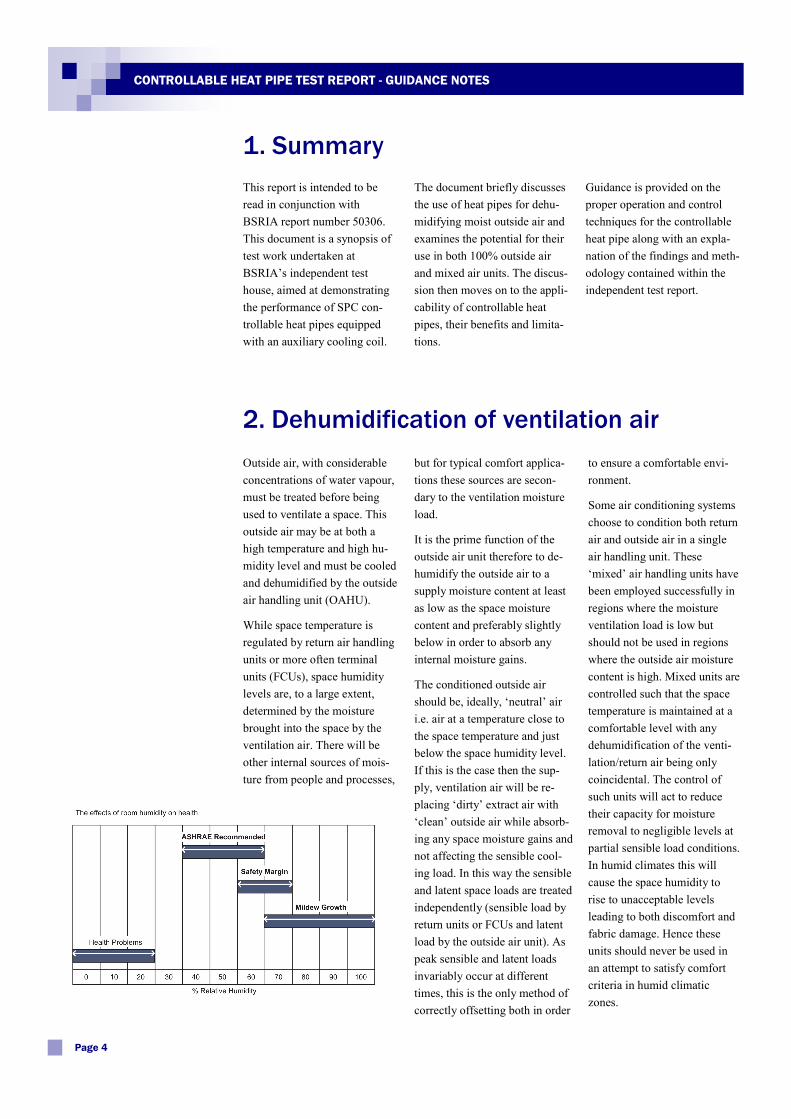
but for typical comfort applica-tions these sources are secon-dary to the ventilation moisture load.
It is the prime function of the outside air unit therefore to de-humidify the outside air to a supply moisture content at least as low as the space moisture content and preferably slightly below in order to absorb any internal moisture gains.
The conditioned outside air should be, ideally, ‘neutral’ air i.e. air at a temperature close to the space temperature and just below the space humidity level. If this is the case then the sup-ply, ventilation air will be re-placing ‘dirty’ extract air with ‘clean’ outside air while absorb-ing any space moisture gains and not affecting the sensible cool-ing load. In this way the sensible and latent space loads are treated independently (sensible load by return units or FCUs and latent load by the outside air unit). As peak sensible and latent loads invariably occur at different times, this is the only method of correctly offsetting both in order
to ensure a comfortable envi-ronment.
Some air conditioning systems choose to condition both return air and outside air in a single air handling unit. These ‘mixed’ air handling units have been employed successfully in regions where the moisture ventilation load is low but should not be used in regions where the outside air moisture content is high. Mixed units are controlled such that the space temperature is maintained at a comfortable level with any dehumidification of the venti-lation/return air being only coincidental. The control of such units will act to reduce their capacity for moisture removal to negligible levels at partial sensible load conditions. In humid climates this will cause the space humidity to rise to unacceptable levels leading to both discomfort and fabric damage. Hence these units should never be used in an attempt to satisfy comfort criteria in humid climatic zones.
Outside air, with considerable concentrations of water vapour, must be treated before being used to ventilate a space. This outside air may be at both a high temperature and high hu-midity level and must be cooled and dehumidified by the outside air handling unit (OAHU).
While space temperature is regulated by return air handling units or more often terminal units (FCUs), space humidity levels are, to a large extent, determined by the moisture brought into the space by the ventilation air. There will be other internal sources of mois-ture from people and processes,
Page 4
CONTROLLABLE HEAT PIPE TEST REPORT - GUIDANCE NOTES
Despite the limitations of mixed air units exposed above they continue to be used in some quantity due to their simplicity and low initial cost compared with more appropriate systems. When equipped with conven-tional cooling coils these units are incapable of providing dual control of temperature and hu-midity. One solution to this problem is to employ a more sophisticated control regime along with a controllable heat pipe to effectively switch the unit between cooling and dehu-
midifying mode.
Certain climatic regions present a more problematical require-ment in terms of the air condi-tioning design. These regions are particularly characterised by zones in Asia which are af-fected by monsoon conditions. In such cases the outside air temperature and sensible load are constant across widely vary-ing ventilation moisture loads. In these instances, one season may be characterised by high temperature and low humidity while the monsoon season can
be characterised by equally high temperature coinciding with high humidity levels. In the dry season there will be a requirement for little or no dehumidification and the out-side air handling unit will be offsetting only a sensible load. Conversely, in the wet season the unit must offset a ventila-tion load the majority of which is latent (moisture). Again, controllable heat pipes could be considered to switch the unit between cooling and dehumidi-fying mode.
3. Heat Pipes for dehumidification
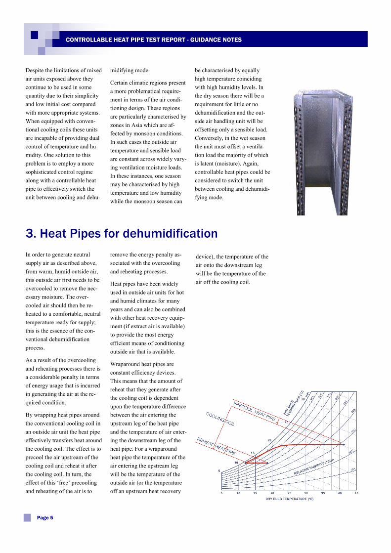
remove the energy penalty as-sociated with the overcooling and reheating processes.
Heat pipes have been widely used in outside air units for hot and humid climates for many years and can also be combined with other heat recovery equip-ment (if extract air is available) to provide the most energy efficient means of conditioning outside air that is available.
Wraparound heat pipes are constant efficiency devices. This means that the amount of reheat that they generate after the cooling coil is dependent upon the temperature difference between the air entering the upstream leg of the heat pipe and the temperature of air enter-ing the downstream leg of the heat pipe. For a wraparound heat pipe the temperature of the air entering the upstream leg will be the temperature of the outside air (or the temperature off an upstream heat recovery
device), the temperature of the air onto the downstream leg will be the temperature of the air off the cooling coil.
In order to generate neutral supply air as described above, from warm, humid outside air, this outside air first needs to be overcooled to remove the nec-essary moisture. The over-cooled air should then be re-heated to a comfortable, neutral temperature ready for supply; this is the essence of the con-ventional dehumidification process.
As a result of the overcooling and reheating processes there is a considerable penalty in terms of energy usage that is incurred in generating the air at the re-quired condition.
By wrapping heat pipes around the conventional cooling coil in an outside air unit the heat pipe effectively transfers heat around the cooling coil. The effect is to precool the air upstream of the cooling coil and reheat it after the cooling coil. In turn, the effect of this ‘free’ precooling and reheating of the air is to
Page 5
CONTROLLABLE HEAT PIPE TEST REPORT - GUIDANCE NOTES
For outside air units the tem-perature of the air off the cool-ing coil would typically be fixed as it is this temperature (close to saturation) which de-termines the moisture content of the supply air. If this tem-perature is fixed then the de-grees of reheating (and there-fore precooling) are determined by the outside air temperature onto the precool leg of the heat pipe. As the temperature of the outside air increases so does the reheat available and vice versa. As a result the temperature of the supply air will vary. With a typical heat pipe system the variation in the supply air tem-
perature will be +/- 2°C around its mean temperature i.e. the supply air temperature might typically vary between 16 and 20°C against a design condition of 18°C. Both extremes of tem-peratures should be considered as comfortable for supply di-rectly to a space. If a heat re-covery device is fitted upstream of the wraparound heat pipe then the effect of variations in outside temperature are damp-ened and a supply temperature variation of only +/-1°C around the mean would be expected.
As the overriding purpose of
the outside air unit in these applications is to remove mois-ture then these slight variations in supply temperature are ac-ceptable with any adjustment to the sensible load being taken care of by the return air or ter-minal units. For the majority of applications, therefore, the recommendation is that wrap-around heat pipes are fitted in outside air units and that these heat pipes are standard units i.e. non-controllable. In certain applications, however, alluded to above, the use of a controlla-ble heat pipe should be consid-ered in line with the informa-tion given below.
4. Controllable heat pipes
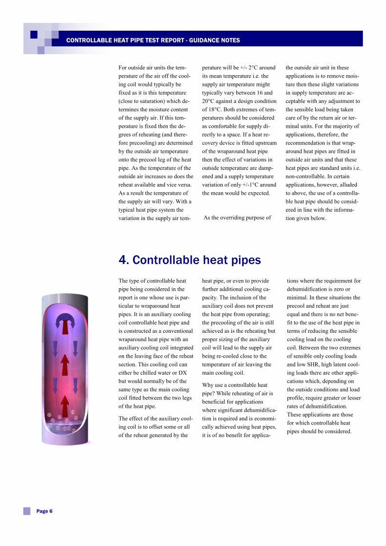
heat pipe, or even to provide further additional cooling ca-pacity. The inclusion of the auxiliary coil does not prevent the heat pipe from operating; the precooling of the air is still achieved as is the reheating but proper sizing of the auxiliary coil will lead to the supply air being re-cooled close to the temperature of air leaving the main cooling coil.
Why use a controllable heat pipe? While reheating of air is beneficial for applications where significant dehumidifica-tion is required and is economi-cally achieved using heat pipes, it is of no benefit for applica-
tions where the requirement for dehumidification is zero or minimal. In these situations the precool and reheat are just equal and there is no net bene-fit to the use of the heat pipe in terms of reducing the sensible cooling load on the cooling coil. Between the two extremes of sensible only cooling loads and low SHR, high latent cool-ing loads there are other appli-cations which, depending on the outside conditions and load profile, require greater or lesser rates of dehumidification. These applications are those for which controllable heat pipes should be considered.
The type of controllable heat pipe being considered in the report is one whose use is par-ticular to wraparound heat pipes. It is an auxiliary cooling coil controllable heat pipe and is constructed as a conventional wraparound heat pipe with an auxiliary cooling coil integrated on the leaving face of the reheat section. This cooling coil can either be chilled water or DX but would normally be of the same type as the main cooling coil fitted between the two legs of the heat pipe.
The effect of the auxiliary cool-ing coil is to offset some or all of the reheat generated by the
Page 6
CONTROLLABLE HEAT PIPE TEST REPORT - GUIDANCE NOTES
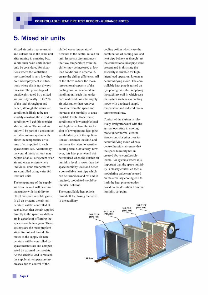
Mixed air units treat return air and outside air in the same unit after mixing in a mixing box. While such basic units should only be considered for situa-tions where the ventilation moisture load is very low they do find employment in situa-tions where this is not always the case. The percentage of outside air treated by a mixed air unit is typically 10 to 20% of the total throughput and hence, although the return air condition is likely to be rea-sonably constant, the mixed air condition will exhibit consider-able variation. The mixed air unit will be part of a constant or variable volume system with either the temperature or vol-ume of air supplied to each space controlled. Additionally, the central mixed air unit may be part of an all air system or an air and water system where individual zone temperatures are controlled using water fed terminal units.
The temperature of the supply air from the unit will be com-mensurate with its ability to offset the space sensible gains. In all air systems the air tem-perature will be controlled at such a level that the air supplied directly to the space via diffus-ers is capable of offsetting the space sensible heat gain. These systems are the most problem-atical for hot and humid cli-mates as the supply air tem-perature will be controlled by space thermostats and compen-sated by external thermostats. As the sensible load is reduced the supply air temperature in-creases due to control of the
chilled water temperature/flowrate to the central mixed air unit. In certain circumstances the flow temperature from the chiller may be increased at low load conditions in order to in-crease the chiller efficiency. All of the above reduce the mois-ture removal capacity of the cooling coil in the central air handling unit such that under part load conditions the supply air adds rather than removes moisture from the space and increases the humidity to unac-ceptable levels. Under these conditions of low sensible load and high latent load the inclu-sion of a wraparound heat pipe would ideally suit the applica-tion as it reduces the SHR and increases the latent to sensible cooling ratio. Conversely, how-ever, this heat pipe would not be required when the outside air humidity level is lower than the space humidity level and hence a controllable heat pipe which can be turned on and off and, if required, modulated would be the ideal solution.
The controllable heat pipe is turned off by closing the valve to the auxiliary
cooling coil in which case the combination of cooling coil and heat pipe behave as though just the conventional heat pipe were present and in this state the assembly is suitable for high latent load operation, known as dehumidifying mode. The con-trollable heat pipe is turned on by opening the valve supplying the auxiliary coil in which case the system switches to cooling mode with a reduced supply temperature and reduced mois-ture removal rate.
Control of the system is rela-tively straightforward with the system operating in cooling mode under normal circum-stances but changing over to dehumidifying mode when a control humidistat senses that the space humidity has in-creased above comfortable levels. For systems where it is important that the space humid-ity is closely controlled then a modulating valve can be used on the auxiliary cooling coil to limit the heat pipe operation based on the deviation from the humidity set point.
5. Mixed air units
Page 7
CONTROLLABLE HEAT PIPE TEST REPORT - GUIDANCE NOTES
Even when 100% dedicated outside air units are used they are only ever designed against a single set of design outside air conditions. When the outside air contains significant concen-trations of moisture it is benefi-cial to employ the wraparound heat pipe. During other seasons, however, while the outside air
remains hot the humidity levels fall below the humidity levels within the conditioned space; at these times the heat pipe can be switched off to provide in-creased sensible cooling capac-ity as there is no dehumidifica-tion requirement.
As the monsoon effect is mark-edly seasonal the switch over
from cooling to dehumidifying mode needs only to be made seasonally and hence the con-trol of the system in its most basic form will only require the seasonal opening and closing of the water valve to the cooling coil. Again if very close control is required the operation of the valve can be modulating.
6. Outside air units for monsoon climates
7. Design and control strategies
ple on-off valve in the flow or return piping to the auxiliary coil. When closed the heat pipe system would operate normally but when driven open the system would revert to a conventional cooling coil with the option for additional sensible cooling ca-pacity.
A modulating system should only be considered if the re-quirement is to very closely control the space humidity. This scenario would not apply to typical comfort conditioning applications. A modulating 3 port valve could be used in order to control the flow rate of chilled water and hence the capacity of the auxiliary coil and the amount or reheat that is negated. The modulating valve should be controlled by an algorithm which reacts to the rate of change of space humidity.
For direct expansion cooling systems the auxiliary cooling coil would also invariably be a DX evaporator coil. The ideal scenario would see this auxiliary coil connected to its own con-
denser set so as to make con-trol as efficient as possible; particularly on/off control whereby the entire auxiliary refrigeration system is either on or off with a reasonable dead band employed to prevent excessive compressor starts. In this instance, if modulating control is required, the auxil-iary refrigeration cycle can be controlled either by using vari-able speed compressor drives or hot gas bypass.
Alternatively, if the auxiliary DX coil needs to be connected to the same refrigeration sys-tem as the main DX cooling coil then it should be fitted with its own expansion device. A solenoid valve should be fitted in the auxiliary DX coil leg upstream of the expansion device along with a check valve in the leg downstream of the coil before it joins with the suction line to the main DX coil. A suction accumulator is also recommended at the com-pressor suction port. In this instance the control of the heat pipe would be only on/off.
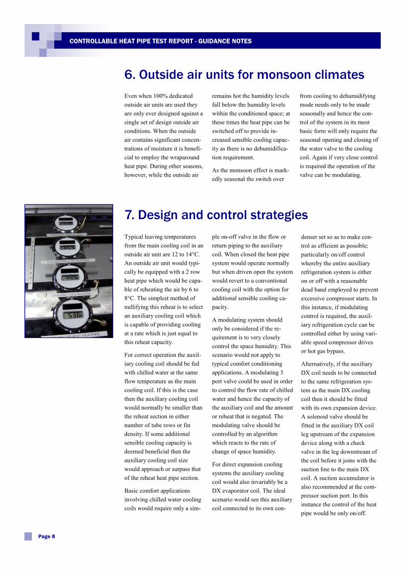
Typical leaving temperatures from the main cooling coil in an outside air unit are 12 to 14°C. An outside air unit would typi-cally be equipped with a 2 row heat pipe which would be capa-ble of reheating the air by 6 to 8°C. The simplest method of nullifying this reheat is to select an auxiliary cooling coil which is capable of providing cooling at a rate which is just equal to this reheat capacity.
For correct operation the auxil-iary cooling coil should be fed with chilled water at the same flow temperature as the main cooling coil. If this is the case then the auxiliary cooling coil would normally be smaller than the reheat section in either number of tube rows or fin density. If some additional sensible cooling capacity is deemed beneficial then the auxiliary cooling coil size would approach or surpass that of the reheat heat pipe section.
Basic comfort applications involving chilled water cooling coils would require only a sim-
Page 8
CONTROLLABLE HEAT PIPE TEST REPORT - GUIDANCE NOTES
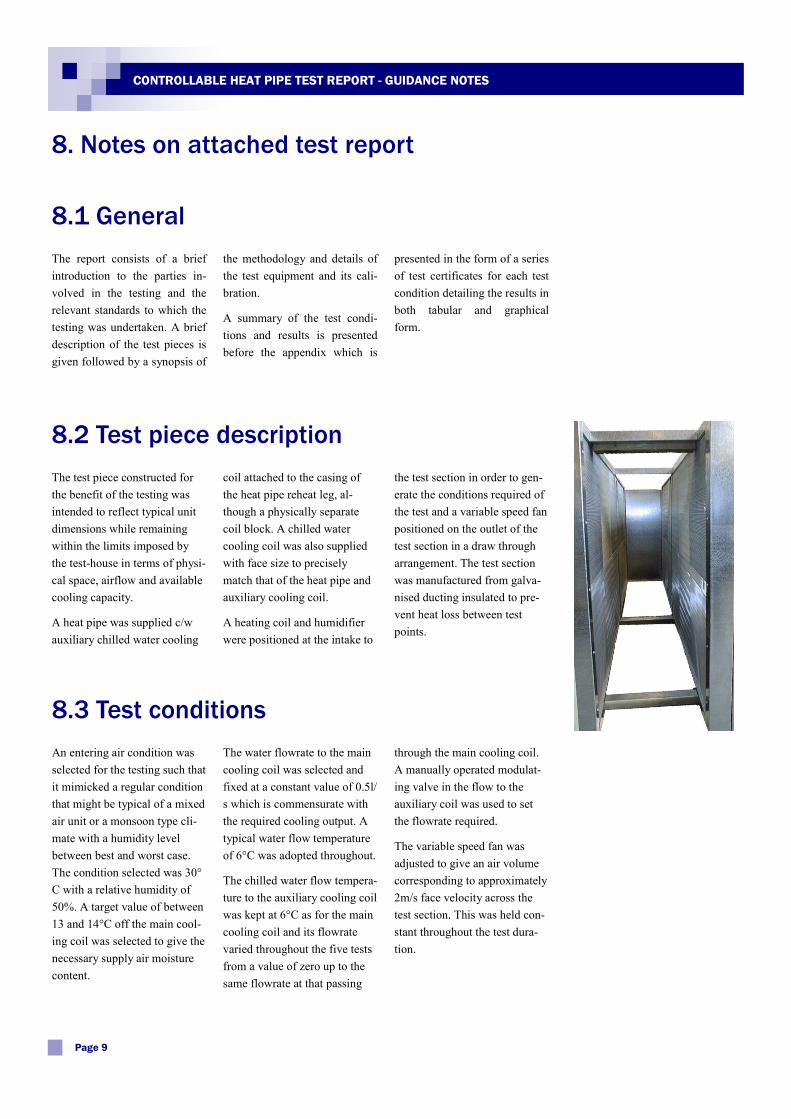
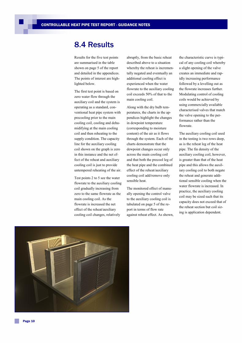
coil attached to the casing of the heat pipe reheat leg, al-though a physically separate coil block. A chilled water cooling coil was also supplied with face size to precisely match that of the heat pipe and auxiliary cooling coil.
A heating coil and humidifier were positioned at the intake to
The test piece constructed for the benefit of the testing was intended to reflect typical unit dimensions while remaining within the limits imposed by the test-house in terms of physi-cal space, airflow and available cooling capacity.
A heat pipe was supplied c/w auxiliary chilled water cooling
the test section in order to gen-erate the conditions required of the test and a variable speed fan positioned on the outlet of the test section in a draw through arrangement. The test section was manufactured from galva-nised ducting insulated to pre-vent heat loss between test points.
8. Notes on attached test report
8.2 Test piece description
8.1 General
the methodology and details of the test equipment and its cali-bration.
A summary of the test condi-tions and results is presented before the appendix which is
presented in the form of a series of test certificates for each test condition detailing the results in both tabular and graphical form.
The report consists of a brief introduction to the parties in-volved in the testing and the relevant standards to which the testing was undertaken. A brief description of the test pieces is given followed by a synopsis of
Page 9
CONTROLLABLE HEAT PIPE TEST REPORT - GUIDANCE NOTES
The water flowrate to the main cooling coil was selected and fixed at a constant value of 0.5l/s which is commensurate with the required cooling output. A typical water flow temperature of 6°C was adopted throughout.
The chilled water flow tempera-ture to the auxiliary cooling coil was kept at 6°C as for the main cooling coil and its flowrate varied throughout the five tests from a value of zero up to the same flowrate at that passing
An entering air condition was selected for the testing such that it mimicked a regular condition that might be typical of a mixed air unit or a monsoon type cli-mate with a humidity level between best and worst case. The condition selected was 30°C with a relative humidity of 50%. A target value of between 13 and 14°C off the main cool-ing coil was selected to give the necessary supply air moisture content.
through the main cooling coil. A manually operated modulat-ing valve in the flow to the auxiliary coil was used to set the flowrate required.
The variable speed fan was adjusted to give an air volume corresponding to approximately 2m/s face velocity across the test section. This was held con-stant throughout the test dura-tion.
8.3 Test conditions
Results for the five test points are summarised in the table shown on page 5 of the report and detailed in the appendices. The points of interest are high-lighted below.
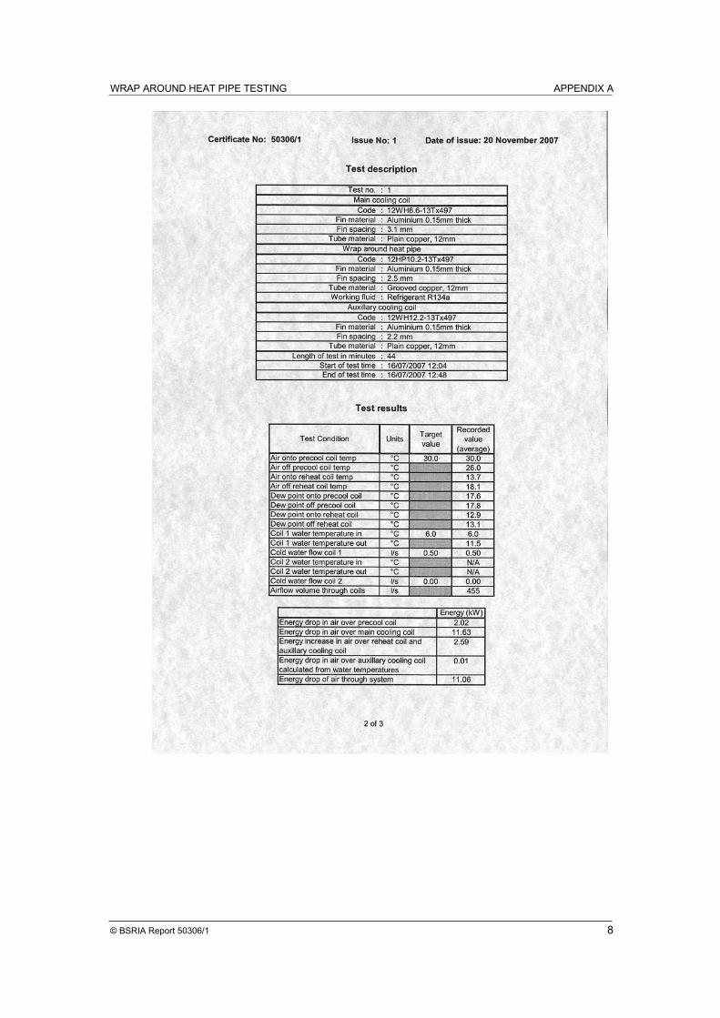
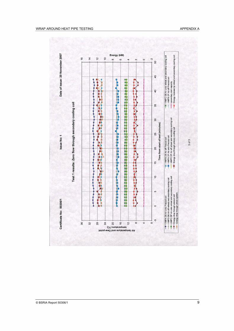
The first test point is based on zero water flow through the auxiliary coil and the system is operating as a standard, con-ventional heat pipe system with precooling prior to the main cooling coil, cooling and dehu-midifying at the main cooling coil and then reheating to the supply condition. The capacity line for the auxiliary cooling coil shown on the graph is zero in this instance and the net ef-fect of the reheat and auxiliary cooling coil is just to provide untempered reheating of the air.
Test points 2 to 5 see the water flowrate to the auxiliary cooling coil gradually increasing from zero to the same flowrate as the main cooling coil. As the flowrate is increased the net effect of the reheat/auxiliary cooling coil changes, relatively
abruptly, from the basic reheat described above to a situation whereby the reheat is incremen-tally negated and eventually an additional cooling effect is experienced when the water flowrate to the auxiliary cooling coil exceeds 50% of that to the main cooling coil.
Along with the dry bulb tem-peratures, the charts in the ap-pendices highlight the changes in dewpoint temperature (corresponding to moisture content) of the air as it flows through the system. Each of the charts demonstrate that the dewpoint changes occur only across the main cooling coil and that both the precool leg of the heat pipe and the combined effect of the reheat/auxiliary cooling coil add/remove only sensible heat.
The monitored effect of manu-ally opening the control valve to the auxiliary cooling coil is tabulated on page 5 of the re-port in terms of flow rate against reheat effect. As shown,
the characteristic curve is typi-cal of any cooling coil whereby a slight opening of the valve creates an immediate and rap-idly increasing performance followed by a levelling out as the flowrate increases further. Modulating control of cooling coils would be achieved by using commercially available characterised valves that match the valve opening to the per-formance rather than the flowrate.
The auxiliary cooling coil used in the testing is two rows deep, as is the reheat leg of the heat pipe. The fin density of the auxiliary cooling coil, however, is greater than that of the heat pipe and this allows the auxil-iary cooling coil to both negate the reheat and generate addi-tional sensible cooling when the water flowrate is increased. In practice, the auxiliary cooling coil may be sized such that its capacity does not exceed that of the reheat section but coil siz-ing is application dependent.
8.4 Results
Page 10
CONTROLLABLE HEAT PIPE TEST REPORT - GUIDANCE NOTES
The controllable heat pipe test-ing was commissioned in order to demonstrate not only the performance of the test pieces constructed but to illustrate the vast range of possibilities avail-able when adopting this type of equipment.
The test pieces were con-structed so as to be typical and representative of the relative sizes of the respective parts of the system, though it must be stressed that each individual application of controllable heat pipes should and will be de-signed as a bespoke system to suit the particular demands imposed.
Conditions chosen for the test-ing again are typical in order to
demonstrate the effect, but they are not necessarily representa-tive of the conditions pertaining to individual applications.
In reading this document and the attached report it should always be borne in mind that controllable heat pipes will not be the solution of choice in the majority of applications. In hot and humid climates which do not exhibit extended dry sea-sons the preferred solution would be to employ standard non-controllable heat pipe sys-tems. These systems are less expensive to purchase and in-stall, require no additional con-trol systems and, being uncon-trolled, maximise the heat re-covery potential.
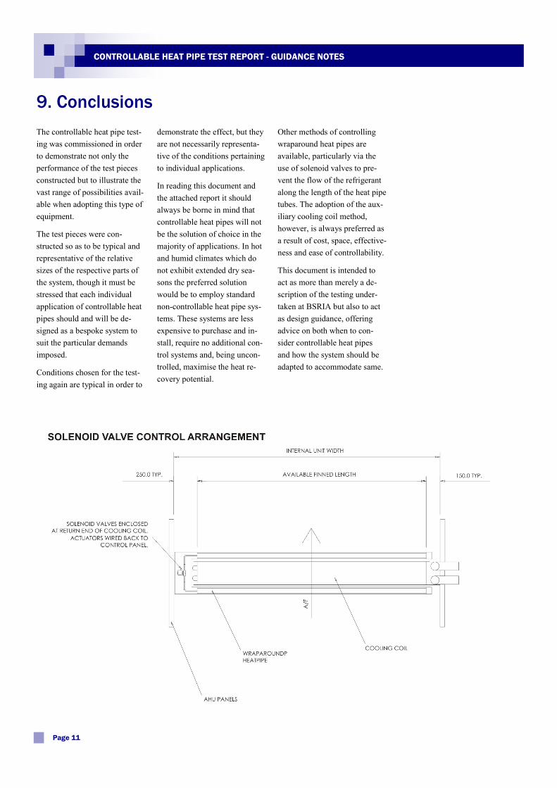
Other methods of controlling wraparound heat pipes are available, particularly via the use of solenoid valves to pre-vent the flow of the refrigerant along the length of the heat pipe tubes. The adoption of the aux-iliary cooling coil method, however, is always preferred as a result of cost, space, effective-ness and ease of controllability.
This document is intended to act as more than merely a de-scription of the testing under-taken at BSRIA but also to act as design guidance, offering advice on both when to con-sider controllable heat pipes and how the system should be adapted to accommodate same.
9. Conclusions
Page 11
CONTROLLABLE HEAT PIPE TEST REPORT - GUIDANCE NOTES

S & P Coil Products Limited SPC House, Evington Valley Road, Leicester, LE5 5LU
tel: +44 (0)116 2490044 fax: +44 (0)116 2490033 email: [email protected] web: www.spcoils.co.uk
Dubai Sales Office tel: +971-4-3341178 fax: +971-4-3341179
India Sales Office
tel: +91-9871134081 fax: +91-11-25612281
Ref: App Notes 003
www.bsria.co.uk
BSRIA Limited
Old Bracknell Lane West, Bracknell, Berkshire RG12 7AH UK
T: +44 (0)1344 465600 F: +44 (0)1344 465626
E: [email protected] W: www.bsria.co.uk
This report must not be reproduced except in full without the written approval of an executive director of BSRIA. It is only intended to be used within the context described in the text.
Report
Wrap Around Heat Pipe Testing
Report 50306/1 December 2007
Carried out for: S & P Coils Products Ltd SPC House
Evington Valley Road Leicester LE5 5LU
Compiled by: Calum Maclean
Quality Approved: GREG KING BSc MSc M.InstR Group Manager MicroClimate & Test
WRAP AROUND HEAT PIPE TESTING CONTENTS
© BSRIA Report 50306/1 1
CONTENTS
1 INTRODUCTION............................................................................................................................. 2
2 TEST ITEM....................................................................................................................................... 2
3 METHOD.......................................................................................................................................... 3
4 INSTRUMENTATION..................................................................................................................... 4
5 RESULTS.......................................................................................................................................... 5
APPENDICES
APPENDIX: A RESULTS CERTIFICATE 50306/1 .......................................................................... 7
APPENDIX: B RESULTS CERTIFICATE 50306/2......................................................................... 10
APPENDIX: C RESULTS CERTIFICATE 50306/3......................................................................... 13
APPENDIX: D RESULTS CERTIFICATE 50306/4 ........................................................................ 16
APPENDIX: E RESULTS CERTIFICATE 50306/5......................................................................... 19
TABLES
Table 1 A list of the test parameters used during the tests............................................................ 5
Table 2 A summary of the energy transfer within the system ...................................................... 5
FIGURES
Figure 1 A diagram of the probe positions during testing.............................................................. 3
WRAP AROUND HEAT PIPE TESTING INTRODUCTION
© BSRIA Report 50306/1 2
1 INTRODUCTION
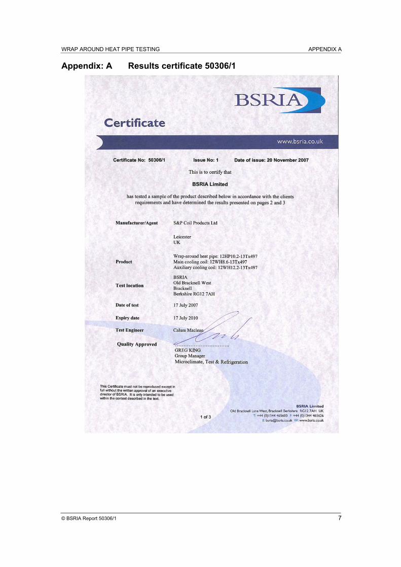
BSRIA received a combined wrap-around heat pipe and auxiliary cooling coil plus main
chilled water-cooling coil from S & P Coil Products Ltd for testing. The aim of testing was to
prove and demonstrate the effect of various flow rates of water through the auxiliary coil in
order to partially and fully negate the reheat effect of the heat pipe.
The test standard was generally in line with BS EN 305 and the conditions at various points
within the ductwork were recorded in order to quantify the performance.
The tests were undertaken between 12 to 17 July 2007.
The tests were conducted within the BSRIA labs in Bracknell.
2 TEST ITEM
BSRIA received the equipment described below from S & P Coil Products Ltd.
Wrap-around heat pipe Code: 12HP10.2-13Tx497
Main cooling coil Code: 12WH8.6-13Tx497
Auxiliary cooling coil Code: 12WH12.2-13Tx497
Appropriate duct connections/heating coils etc.
The heat pipe and cooling coil blocks were all from standard copper tube/aluminium fin
construction. Working fluid in the heat pipes was R134a. Fin spacing for the individual
elements are giving in the codes above.
WRAP AROUND HEAT PIPE TESTING METHOD
© BSRIA Report 50306/1 3
3 METHOD
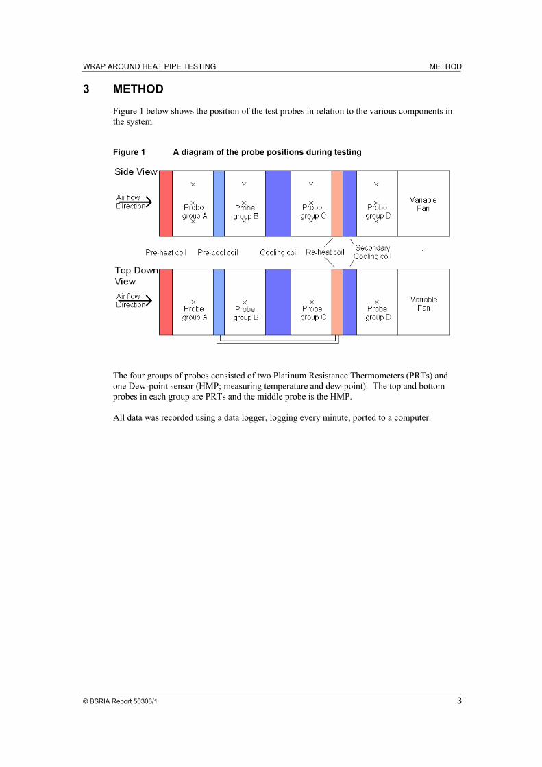
Figure 1 below shows the position of the test probes in relation to the various components in
the system.
Figure 1 A diagram of the probe positions during testing
The four groups of probes consisted of two Platinum Resistance Thermometers (PRTs) and
one Dew-point sensor (HMP; measuring temperature and dew-point). The top and bottom
probes in each group are PRTs and the middle probe is the HMP.
All data was recorded using a data logger, logging every minute, ported to a computer.
WRAP AROUND HEAT PIPE TESTING INSTRUMENTATION
© BSRIA Report 50306/1 4
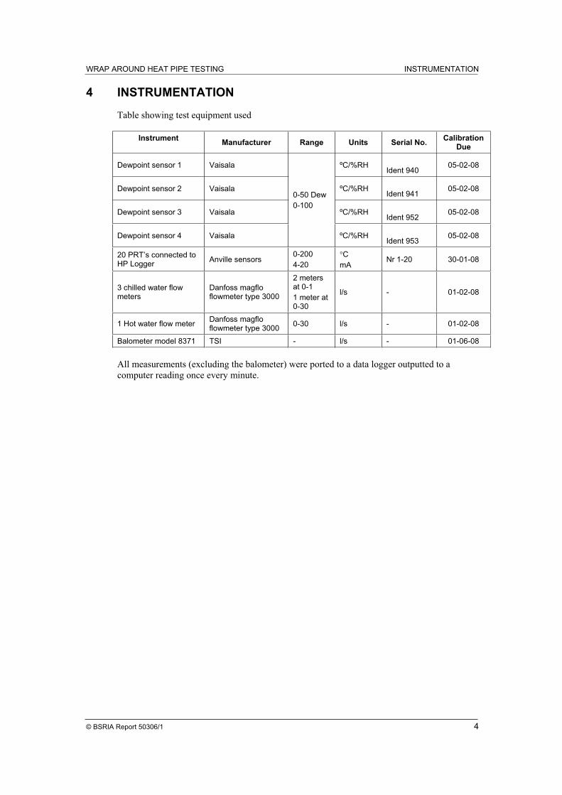
4 INSTRUMENTATION
Table showing test equipment used
Instrument Manufacturer Range Units Serial No.
Calibration Due
Dewpoint sensor 1 Vaisala ºC/%RH Ident 940
05-02-08
Dewpoint sensor 2 Vaisala ºC/%RH Ident 941
05-02-08
Dewpoint sensor 3 Vaisala ºC/%RH Ident 952
05-02-08
Dewpoint sensor 4 Vaisala
0-50 Dew
0-100
ºC/%RHIdent 953
05-02-08
20 PRT’s connected to HP Logger
Anville sensors 0-200
4-20
C
mA Nr 1-20 30-01-08
3 chilled water flow meters
Danfoss magflo flowmeter type 3000
2 meters at 0-1
1 meter at 0-30
l/s - 01-02-08
1 Hot water flow meter Danfoss magflo flowmeter type 3000
0-30 l/s - 01-02-08
Balometer model 8371 TSI - l/s - 01-06-08
All measurements (excluding the balometer) were ported to a data logger outputted to a
computer reading once every minute.
WRAP AROUND HEAT PIPE TESTING RESULTS
© BSRIA Report 50306/1 5
5 RESULTS
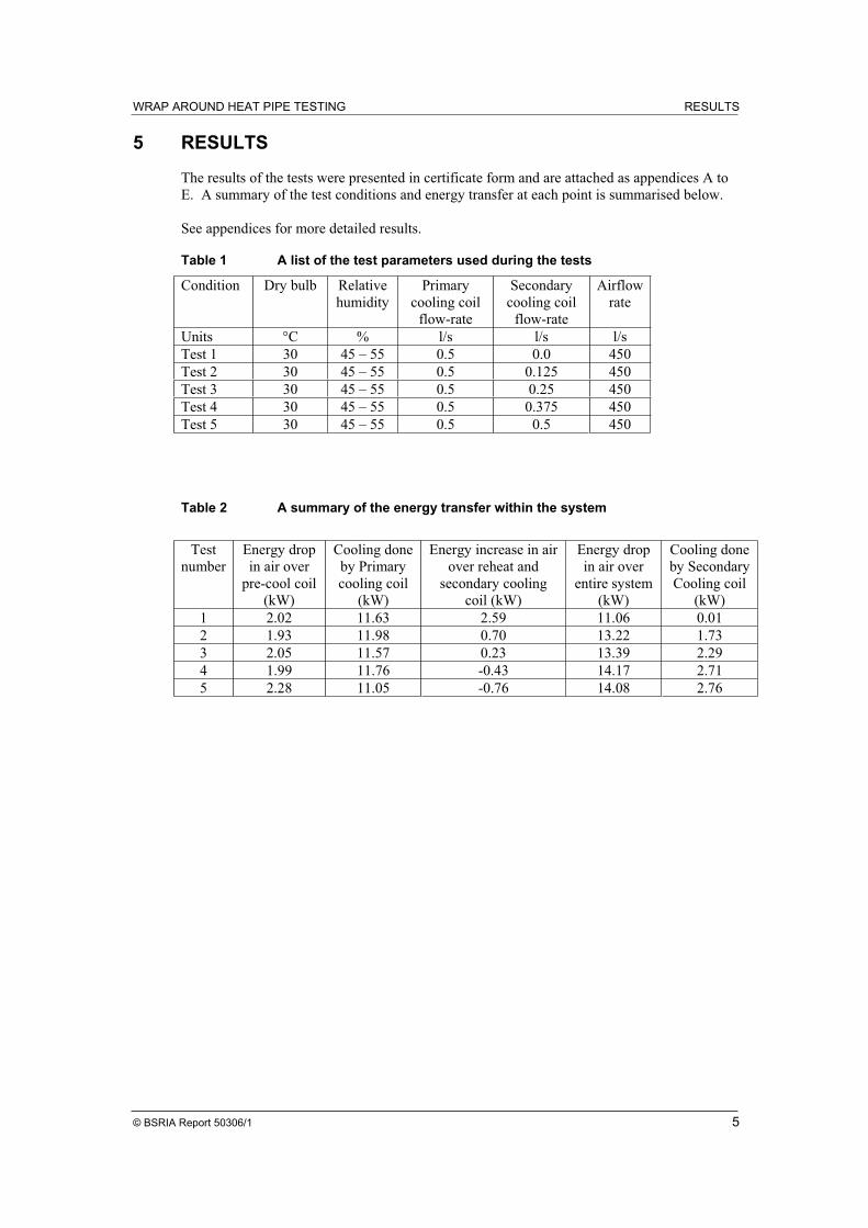
The results of the tests were presented in certificate form and are attached as appendices A to
E. A summary of the test conditions and energy transfer at each point is summarised below.
See appendices for more detailed results.
Table 1 A list of the test parameters used during the tests
Condition Dry bulb Relative
humidity
Primary
cooling coil
flow-rate
Secondary
cooling coil
flow-rate
Airflow
rate
Units °C % l/s l/s l/s
Test 1 30 45 – 55 0.5 0.0 450
Test 2 30 45 – 55 0.5 0.125 450
Test 3 30 45 – 55 0.5 0.25 450
Test 4 30 45 – 55 0.5 0.375 450
Test 5 30 45 – 55 0.5 0.5 450
Table 2 A summary of the energy transfer within the system
Test
number
Energy drop
in air over
pre-cool coil
(kW)
Cooling done
by Primary
cooling coil
(kW)
Energy increase in air
over reheat and
secondary cooling
coil (kW)
Energy drop
in air over
entire system
(kW)
Cooling done
by Secondary
Cooling coil
(kW)
1 2.02 11.63 2.59 11.06 0.01
2 1.93 11.98 0.70 13.22 1.73
3 2.05 11.57 0.23 13.39 2.29
4 1.99 11.76 -0.43 14.17 2.71
5 2.28 11.05 -0.76 14.08 2.76
WRAP AROUND HEAT PIPE TESTING APPENDICES
© BSRIA Report 50306/1 6
APPENDICES
WRAP AROUND HEAT PIPE TESTING APPENDIX A
© BSRIA Report 50306/1 7
Appendix: A Results certificate 50306/1
WRAP AROUND HEAT PIPE TESTING APPENDIX A
© BSRIA Report 50306/1 8
WRAP AROUND HEAT PIPE TESTING APPENDIX A
© BSRIA Report 50306/1 9
WRAP AROUND HEAT PIPE TESTING APPENDIX B
© BSRIA Report 50306/1 10
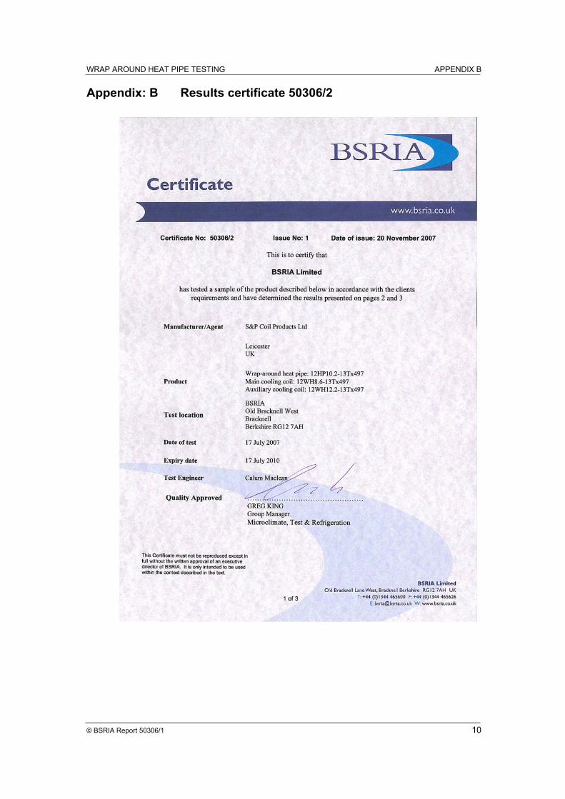
Appendix: B Results certificate 50306/2