controldraw demonstration a safety shutdown system … · low low fuel 03 economiser header gas...
TRANSCRIPT
ControlDraw Demonstration A Safety Shutdown System Model
Print and Review Report
Thanks to Horizon Consulting for the original documentshttp://www.horizonconsultants.com
Note - only selected portions of the model are in this PDF
Project : Horizon Demo Model
De m
onstra
tion
ControlDraw Users Page: 1 of 21
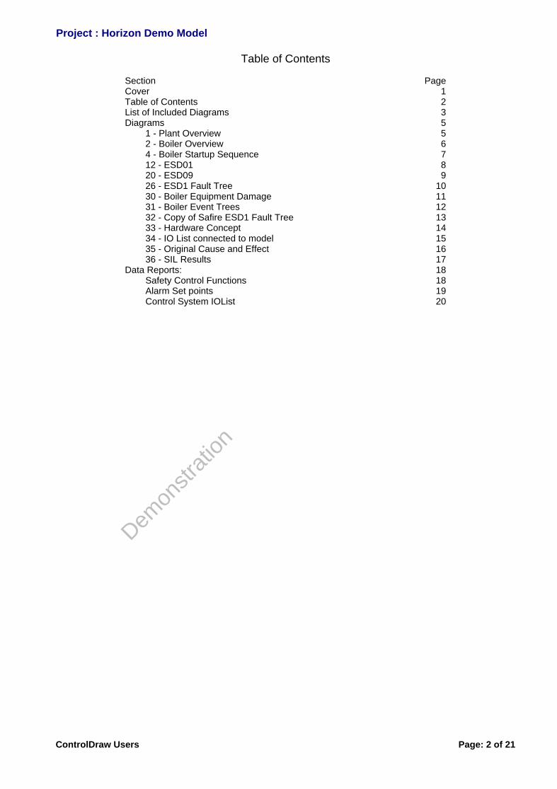
Table of Contents
Section PageCover 1Table of Contents 2List of Included Diagrams 3Diagrams 5 1 - Plant Overview 5 2 - Boiler Overview 6 4 - Boiler Startup Sequence 7 12 - ESD01 8 20 - ESD09 9 26 - ESD1 Fault Tree 10 30 - Boiler Equipment Damage 11 31 - Boiler Event Trees 12 32 - Copy of Safire ESD1 Fault Tree 13 33 - Hardware Concept 14 34 - IO List connected to model 15 35 - Original Cause and Effect 16 36 - SIL Results 17Data Reports: 18 Safety Control Functions 18 Alarm Set points 19 Control System IOList 20
Project : Horizon Demo Model
De m
onstra
tion
ControlDraw Users Page: 2 of 21

List of Included Diagrams
Diagram Objs Class Vers Lastauthor Date
1 Plant Overview 27 Process Cell 107 Francis Lovering 23-Jan-05
2 Boiler Overview 68 Unit 108 Francis Lovering 23-Jan-05
4 Boiler Startup Sequence 22 Phase 107 Francis Lovering 23-Jan-05
12 ESD01 6 Safety Control Function 122 Francis Lovering 08-Feb-05
20 ESD09 3 Safety Control Function 96 Francis Lovering 23-Jan-05
26 ESD1 Fault Tree 25 Control Module 121 Francis Lovering 03-Feb-05
30 Boiler Equipment Damage 12 Document Reference 103 Francis Lovering 23-Jan-05
31 Boiler Event Trees 25 Document Reference 103 Francis Lovering 23-Jan-05
32 Copy of Safire ESD1 Fault Tree 2 None 111 Francis Lovering 23-Jan-05
33 Hardware Concept 15 None 109 Francis Lovering 23-Jan-05
34 IO List connected to model 1 None 108 Francis Lovering 23-Jan-05
35 Original Cause and Effect 2 None 119 Francis Lovering 01-Feb-05
36 SIL Results 2 None 97 Francis Lovering 23-Jan-05
Project : Horizon Demo Model
De m
onstra
tion
ControlDraw Users Page: 3 of 21

Project : Horizon Demo Model
De m
o n stra
tion
ControlDraw Users Page: 4 of 21
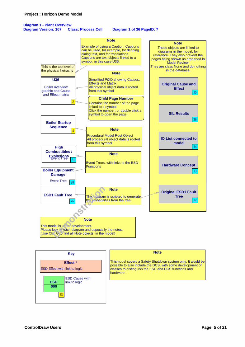
Diagram 1 - Plant OverviewDiagram Version: 107 Class: Process Cell Diagram 1 of 36 PageID: 7
NoteThese objects are linked todiagrams in the model, for
reference. They also prevent thepages being shown as orphaned in
Model Review.They are class None and do nothing
in the database.
Key
U36
Boiler overviewgraphic and Causeand Effect matrix
Hardware Concept
Boiler StartupSequence
HighCombustibles /
ExplosionsEvent Tree
Original Cause andEffect
SIL Results
IO List connected tomodel
Note
This model is under development. Please look at each diagram and especially the notes.(Use Ctrl_G to find all Note objects in the model)
Boiler EquipmentDamage
Event Tree
NoteThese objects are linked todiagrams in the model, for
reference. They also prevent thepages being shown as orphaned in
Model Review.They are class None and do nothing
in the database.
Hardware Concept
Original Cause andEffect
SIL Results
IO List connected tomodel
Note
Simplified P&ID showing Causes, Effects and Matrix.All physical object data is rooted from this symbol
Note
Event Trees, with links to the ESD Functions
Child Page NumberContains the number of the page linked to a symbol.Click the number, or double click a symbol to open the page.
Note
Procedural Model Root ObjectAll procedural object data is rooted from this symbol
ESD1 Fault Tree
Note
This diagram is scripted to generatethe probabilities from the tree.
Original ESD1 FaultTree
Effect *
ESD Effect with link to logic
ESD Cause with link to logicESD
000
Note
Thismodel covers a Safety Shutdown system only. It would be possible to also include the DCS, with some development of classes to distinguish the ESD and DCS functions and hardware.
Note
Example of using a Caption, Captions can be used, for example, for defining dialog text, and for translationsCaptions are text objects linked to a symbol, in this case U36.
This is the top level ofthe physical heirachy
2
33
4
31
35
36
34
30
33
35
36
34
26 32
23
Project : Horizon Demo Model
De m
o n stra
tion
ControlDraw Users Page: 5 of 21
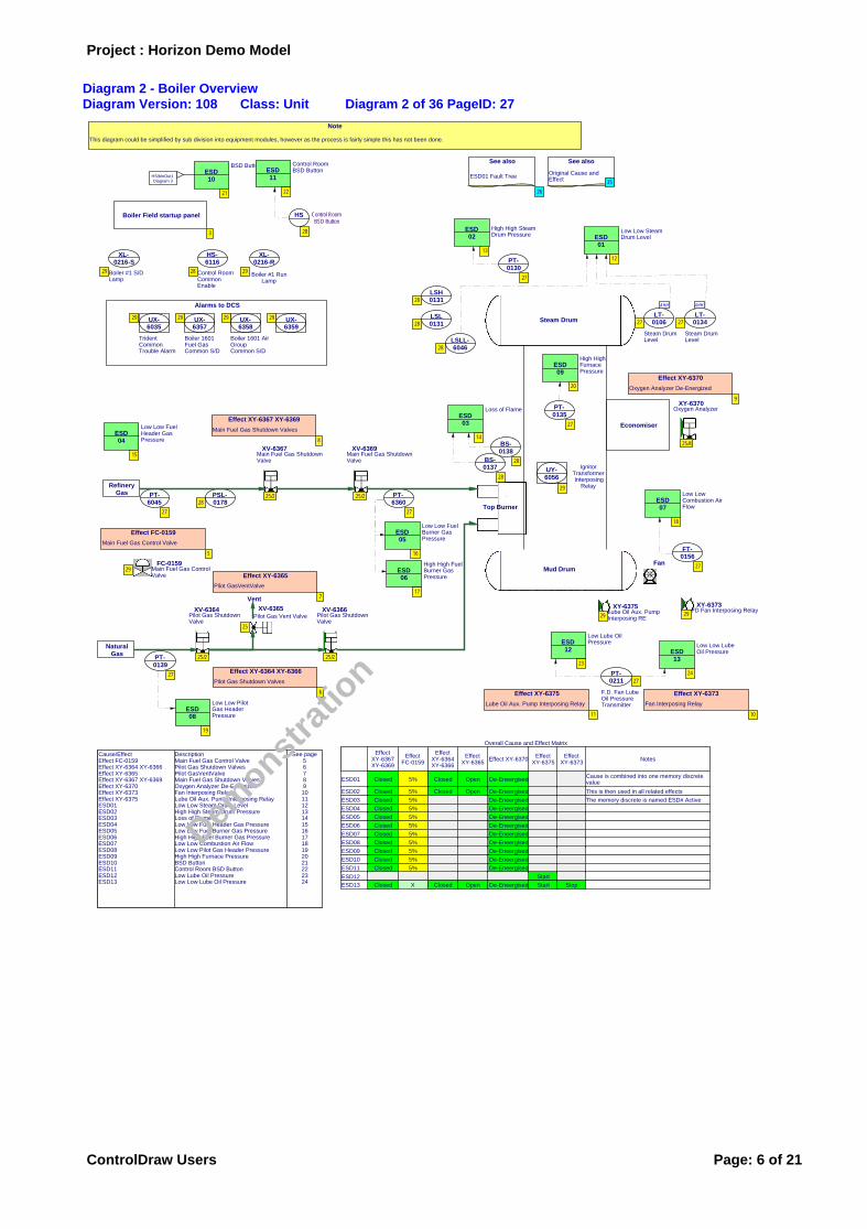
Diagram 2 - Boiler OverviewDiagram Version: 108 Class: Unit Diagram 2 of 36 PageID: 27
Low Low Steam Drum LevelESD
01
Trident Common Trouble Alarm
UX-6035
Overall Cause and Effect Matrix
ESD01
ESD02
ESD03
ESD04
ESD05
ESD06
ESD07
ESD08
ESD09
ESD10
ESD11
ESD12
ESD13
EffectXY-6367XY-6369
Closed
Closed
Closed
Closed
Closed
Closed
Closed
Closed
Closed
Closed
Closed
Closed
EffectFC-0159
5%
5%
5%
5%
5%
5%
5%
5%
5%
5%
5%
X
EffectXY-6364XY-6366
Closed
Closed
Closed
EffectXY-6365
Open
Open
Open
Effect XY-6370
De-Eneergised
De-Eneergised
De-Eneergised
De-Eneergised
De-Eneergised
De-Eneergised
De-Eneergised
De-Eneergised
De-Eneergised
De-Eneergised
De-Eneergised
De-Eneergised
EffectXY-6375
Start
Start
EffectXY-6373
Stop
Notes
Cause is combined into one memory discrete value
This is then used in all related effects
The memory discrete is named ESD# Active
Effect XY-6367 XY-6369
Main Fuel Gas Shutdown Valves
Cause/EffectEffect FC-0159Effect XY-6364 XY-6366Effect XY-6365Effect XY-6367 XY-6369Effect XY-6370Effect XY-6373Effect XY-6375ESD01ESD02ESD03ESD04ESD05ESD06ESD07ESD08ESD09ESD10ESD11ESD12ESD13
DescriptionMain Fuel Gas Control ValvePilot Gas Shutdown ValvesPilot GasVentValveMain Fuel Gas Shutdown ValvesOxygen Analyzer De-EnergizedFan Interposing RelayLube Oil Aux. Pump Interposing RelayLow Low Steam Drum LevelHigh High Steam Drum PressureLoss of FlameLow Low Fuel Header Gas PressureLow Low Fuel Burner Gas PressureHigh High Fuel Burner Gas PressureLow Low Combustion Air FlowLow Low Pilot Gas Header PressureHigh High Furnace PressureBSD ButtonControl Room BSD ButtonLow Lube Oil PressureLow Low Lube Oil Pressure
See page56789101112131415161718192021222324
IgnitorTransformerInterposing
Relay
UY-6056
Effect FC-0159
Main Fuel Gas Control Valve
High High SteamDrum Pressure
ESD02
Effect XY-6364 XY-6366
Pilot Gas Shutdown Valves
Boiler 1601 Fuel Gas Common S/D
UX-6357
Boiler 1601 Air Group Common S/D
UX-6358
Effect XY-6365
Pilot GasVentValve
UX-6359
Effect XY-6370
Oxygen Analyzer De-Energized
Boiler #1 RunLamp
XL-0216-R
Effect XY-6375
Lube Oil Aux. Pump Interposing Relay
Boiler #1 S/D Lamp
XL-0216-S
Effect XY-6373
Fan Interposing Relay
BSD ButtonESD10
Low Low Fuel Burner Gas Pressure
ESD05
High High Fuel Burner Gas Pressure
ESD06
Low Low Pilot Gas Header Pressure
ESD08
High High Furnace Pressure
ESD09
LSLL-6046
Steam Drum Level
LT-0106
AHH
Steam Drum Level
LT-0134
AHH
PT-0130
BS-0138
BS-0137
Control Room Common Enable
HS-6116
PT-6045
PT-6360
FT-0156
PT-0139
PT-0135
See also
ESD01 Fault Tree
F.D. Fan Lube Oil Pressure Transmitter
PT-0211
XV-6367Main Fuel Gas Shutdown Valve
XV-6369Main Fuel Gas Shutdown Valve
FC-0159Main Fuel Gas Control Valve
XV-6366Pilot Gas Shutdown Valve
XV-6364Pilot Gas Shutdown Valve
XV-6365Pilot Gas Vent Valve
XY-6370Oxygen Analyzer
XY-6375Lube Oil Aux. Pump Interposing RE
XY-6373FD Fan Interposing Relay
Steam Drum
Mud Drum
NaturalGas
Top Burner
RefineryGas
Vent
PSL-0178
Boiler Field startup panel
Alarms to DCS
LSL0131
LSH0131
Loss of FlameESD03 EconomiserLow Low Fuel
Header Gas Pressure
ESD04
Control RoomBSD Button
HS
Control Room BSD ButtonESD
11
Fan
Low Lube Oil PressureESD
12Low Low Lube Oil PressureESD
13
Low Low Combustion Air Flow
ESD07
See also
Original Cause and Effect
Note
This diagram could be simplified by sub division into equipment modules, however as the process is fairly simple this has not been done.
HS/blnOut1Diagram 3
12
29
29
13
29 29 29
29 29
16
17
19
20
28
27 27
27
28
28
28
27 27
27
27
27
26
27
25/2 25/2
29
25/2 25/2
25
25/4
29 29
28
3
28
28
8
5
6
7
9
11 10
14
15
21
28
22
23
24
18
35
Project : Horizon Demo Model
De m
o n stra
tion
ControlDraw Users Page: 6 of 21

Diagram 4 - Boiler Startup SequenceDiagram Version: 107 Class: Phase Diagram 4 of 36 PageID: 21
S01 StartF.D. Fan
Operator Prompt
T 01 Start
T02 F.D. Fan Running
Operator Confirm
S 02 VerifyPurge
T 03
FT-0156.AL = FalseFT-0156.AH = False
S 03Permissives
T 04
XV-6364.DIClosed = True 'Pilot Gas Block Valves ClosedXV-6366.DIClosed = TrueXV-6367.DIClosed = True 'Fuel Gas Block Valves ClosedXV-6369.DIClosed = TrueBS-0137.DI = True 'Flame not presentBS-0138.DI = True
NoteThis diagram is under development. The Flowchart is not complete, but at present shows how the model can represent the flowchart using Special '_SetSymbols' objects. These link the text in the steps to the obects in the model. This ensures that object references are correct, and that tagname changes propagate.The Flowchart has been converted to a Sequential Function Chart.
Startup Sequence.pdf
(Source files reference object)The flowchart is an image from the Horizon Visio-Boiler StartupSequence.pdf file. It will be deleted, leaving just this document
reference when the sequence in the model is appproved.
Review Status:Under Development
Note
ReviewStatus special object -shows the development status of the diagram as set in page details.
Note
_SetSymbols special objects - show a list of settings for objects in the model
S 04
T 05
PT-6360.AHH = OffPT-6045.ALL = OffPT-0130.AHH = OffESD01 Active = False
S 05
T 06
S 06
T 07
Project : Horizon Demo Model
De m
onstra
tion
ControlDraw Users Page: 7 of 21

Description for Diagram 12 - ESD01Low Low Steam Drum Level
Diagram 12 - ESD01Diagram Version: 122 Class: Safety Control Function Diagram 12 of 36 PageID: 17
2oo3
ESD01 ActiveLow Low Steam Drum Level
LT-0106.AHH[Diagram 2]
LSLL-6046.blnVal[Diagram 2]
LT-0134.AHH
[Diagram 2]
Cross Reference
TagnameESD01 Active
Diagram58
Used by
Project : Horizon Demo Model
De m
onstra
tion
ControlDraw Users Page: 8 of 21
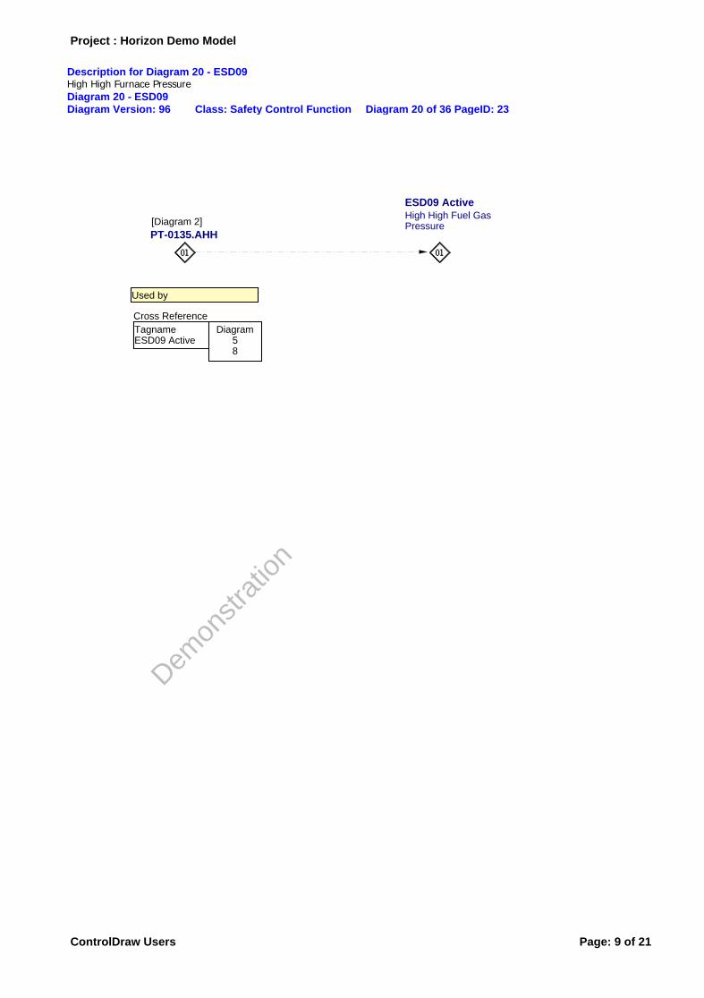
Description for Diagram 20 - ESD09High High Furnace Pressure
Diagram 20 - ESD09Diagram Version: 96 Class: Safety Control Function Diagram 20 of 36 PageID: 23
ESD09 ActiveHigh High Fuel Gas Pressure
PT-0135.AHH[Diagram 2]
Cross Reference
TagnameESD09 Active
Diagram58
Used by
Project : Horizon Demo Model
De m
onstra
tion
ControlDraw Users Page: 9 of 21
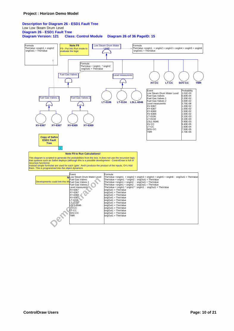
Description for Diagram 26 - ESD1 Fault TreeLow Low Steam Drum Level
Diagram 26 - ESD1 Fault TreeDiagram Version: 121 Class: Control Module Diagram 26 of 36 PageID: 15
XY-6367XV-6367
Fuel Gas Valves 1
XY-6369XV-6369
Fuel Gas Valves 2
Fuel Gas Valves
EventLow Steam Drum Water LevelFuel Gas ValvesFuel Gas Valves 1Fuel Gas Valves 2Level measurentsXV-6367XY-6367XY-6369XV-6369LT-0106LT-0134LSLL-6046XV-CCLT-CCSOV-CCTMR
Probability1.01E-036.60E-042.20E-023.00E-023.75E-081.20E-021.00E-021.50E-021.50E-023.10E-033.10E-033.90E-039.40E-051.50E-047.50E-052.70E-05
LT-0134LT-0106
Level measurents
LSLL-6046
LT-CCXV-CC
Low Steam Drum WaterLevel
SOV-CC TMR
FormulaTheValue =sngIn1 + sngIn2 sngOut1 = TheValue
FormulaTheValue = sngIn1 * sngIn2 sngOut1 = TheValue
FormulaTheValue =sngIn1 + sngIn2 + sngIn3 + sngIn4 + sngIn5 + sngIn6 sngOut1 = TheValue
Copy of SafireESD1 Fault
Tree
Note F9 to Run Calculations!
This diagram is scripted to generate the probabilities from the tree. It does not use the recursive logic that systems such as Safire deploys (although this is a possible development - ControlDraw is full of recursive functions)Instead simple formulae are used for each 'gate'. And's produce the product of the inputs, Or's Add them. This is programmed into the object dynamics.
Note Safire Links!
Developments could link this Model to the Safire model, if Safire is to be retained.
Note F9F9 - Put into Run mode to evaluate the logic
EventLow Steam Drum Water LevelFuel Gas ValvesFuel Gas Valves 1Fuel Gas Valves 2Level measurentsXV-6367XY-6367XY-6369XV-6369LT-0106LT-0134LSLL-6046XV-CCLT-CCSOV-CCTMR
FormulaTheValue =sngIn1 + sngIn2 + sngIn3 + sngIn4 + sngIn5 + sngIn6 : sngOut1 = TheValueTheValue = sngIn1 * sngIn2 : sngOut1 = TheValueTheValue =sngIn1 + sngIn2 : sngOut1 = TheValueTheValue =sngIn1 + sngIn2 : sngOut1 = TheValueTheValue = sngIn1 * sngIn2 * sngIn3 : sngOut1 = TheValuesngOut1 = TheValuesngOut1 = TheValuesngOut1 = TheValuesngOut1 = TheValuesngOut1 = TheValuesngOut1 = TheValuesngOut1 = TheValuesngOut1 = TheValuesngOut1 = TheValuesngOut1 = TheValuesngOut1 = TheValue
32
Project : Horizon Demo Model
De m
o n stra
tion
ControlDraw Users Page: 10 of 21

Diagram 30 - Boiler Equipment DamageDiagram Version: 103 Class: Document Reference Diagram 30 of 36 PageID: 24
High SteamPressure
Low SteamDrum Level
Equipment Damage
Loss ofDownstream
Users
Boiler FeedpumpsFailure
Boiler FeedWater Flow Ctrl
Fail
TubeRupture
Note
This diagram is shows how an Event Tree can be drawn and linked to the relevantdiagrams. The links are jumps because the diagram is informative rather than being data generating. An alternative structure could be used where this type of diagram is actually a data generating parent however at present this model is not structured that way.
Low Low Steam Drum Level
ESD01
[Diagram 2]
ESD02
[Diagram 2]
Low Lube OilPressure
ESD12
[Diagram 2]
Low Low Lube Oil Pressure
ESD13
[Diagram 2] 12 13
23
24
Project : Horizon Demo Model
De m
o n stra
tion
ControlDraw Users Page: 11 of 21
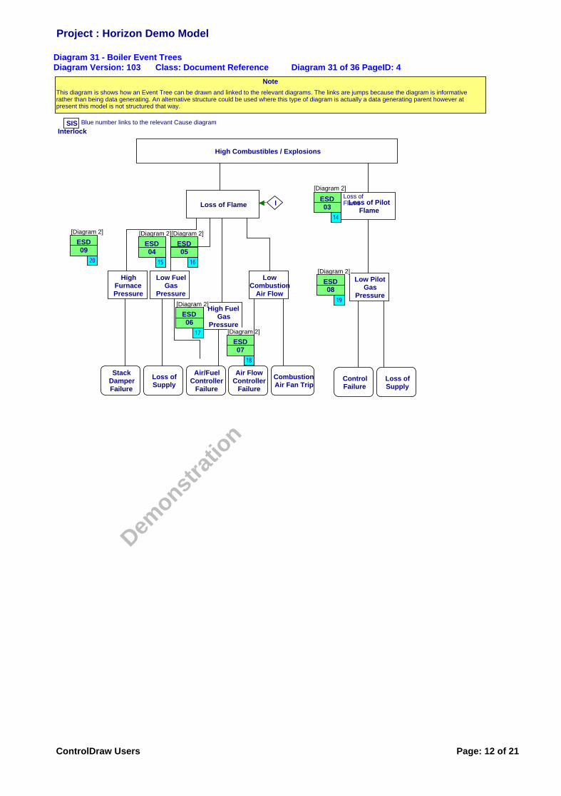
Diagram 31 - Boiler Event TreesDiagram Version: 103 Class: Document Reference Diagram 31 of 36 PageID: 4
HighFurnacePressure
Low FuelGas
Pressure
LowCombustion
Air Flow
High FuelGas
Pressure
Low PilotGas
Pressure
Loss of Flame Loss of PilotFlame
High Combustibles / Explosions
I
SISInterlock
Blue number links to the relevant Cause diagram
StackDamperFailure
Loss ofSupply
Air/FuelController
Failure
CombustionAir Fan Trip
Loss ofSupply
Air FlowController
Failure
ControlFailure
Note
This diagram is shows how an Event Tree can be drawn and linked to the relevant diagrams. The links are jumps because the diagram is informative rather than being data generating. An alternative structure could be used where this type of diagram is actually a data generating parent however at present this model is not structured that way.
ESD05
[Diagram 2]
ESD08
[Diagram 2]
ESD09
[Diagram 2]
Loss of Flame
ESD03
[Diagram 2]
ESD04
[Diagram 2]
ESD07
[Diagram 2]
ESD06
[Diagram 2]
16
17
19
20
14
15
18
Project : Horizon Demo Model
De m
o n stra
tion
ControlDraw Users Page: 12 of 21

Diagram 32 - Copy of Safire ESD1 Fault TreeDiagram Version: 111 Class: None Diagram 32 of 36 PageID: 19
Safire version
Project : Horizon Demo Model
De m
o n stra
tion
ControlDraw Users Page: 13 of 21
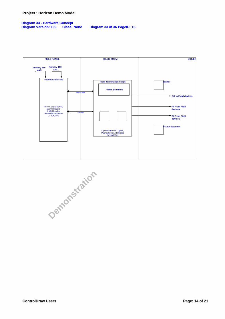
Diagram 33 - Hardware ConceptDiagram Version: 109 Class: None Diagram 33 of 36 PageID: 16
Trident Enclosure
Trident Logic Solver,Comm Module& I/O Modules
Redundant Acopian24VDC P/S
RACK ROOM
Field Termination Strips
Operator Panels, Lights,Pushbuttons and Bypass
Keyswitches
Flame Scanners
FIELD PANEL BOILER
Ignitor
DO to Field devices
Flame Scanners
Primary 110VAC
AI From Field devices
DI From Field devices
Primary 110VAC
Fibre cable
Homerun cable
Project : Horizon Demo Model
De m
o n stra
tion
ControlDraw Users Page: 14 of 21
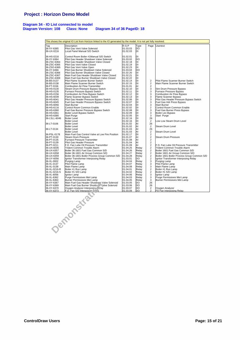
Diagram 34 - IO List connected to modelDiagram Version: 108 Class: None Diagram 34 of 36 PageID: 18
Tag36-XY-636536-UX-0216
36-HS-021636-XY-636436-ZSC-636436-ZSC-636536-ZSO-636536-XY-636636-ZSC-636636-ZSC-636736-ZSC-636936-BS-013736-BS-013836-FT-015636-HS-013036-HS-013536-HS-015636-HS-603936-HS-604136-HS-604536-HS-605636-HS-611636-HS-636036-HS-636136-HS-638036-LSLL-6046
36-LT-0106
36-LT-0134
36-PSL-017836-PT-013036-PT-013536-PT-013936-PT-021136-UX-603536-UX-635736-UX-635836-UX-635936-UY-605636-XL-000236-XL-013736-XL-013836-XL-0216-R36-XL-0216-S36-XL-605636-XL-636236-XL-636336-XY-636736-XY-636936-XY-637036-XY-6373
DescriptionPilot Gas Vent Valve SolenoidLocal Panel Manual S/D Switch
Control Room Boiler #1Manual S/D SwitchPilot Gas Header Shutdown Valve SolenoidPilot Gas Header Shutdown Valve ClosedPilot Gas Vent Valve ClosedPilot Gas Vent Valve OpenPilot Gas Burner Shutdown Valve SolenoidPilot Gas Burner Shutdown Valve ClosedMain Fuel Gas Header Shutdown Valve ClosedMain Fuel Gas Burner Shutdown Valve ClosedPilot Flame Scanner Burner SwitchMain Flame Scanner Burner SwitchCombustion Air Flow TransmitterSteam Drum Pressure Bypass SwitchFurnace Pressure Bypass SwitchCombustion Air Flow Bypass SwitchFlame Scanner Bypass SwitchPilot Gas Header Pressure Bypass SwitchFuel Gas Header Pressure Bypass SwitchStart BurnerControl Room Common EnableFuel Gas Burner Pressure Bypass SwitchBoiler Level Bypass SwitchStart PurgeBoiler LevelBoiler LevelBoiler LevelBoiler LevelBoiler LevelBoiler LevelMain Fuel Gas Control Valve at Low Fire PositionSteam Drum PressureFurnace Pressure TransmitterPilot Gas Header PressureF.D. Fan Lube Oil Pressure TransmitterTrident Common Trouble AlarmBoiler 36-1601 Fuel Gas Common S/DBoiler 36-1601 Air Group Common S/DBoiler 36-1601 Boiler Process Group Common S/DIgnitor Transformer Interposing RelayPurging LampPilot Flame LampMain Flame LampBoiler #1 Run LampBoiler #1 S/D LampIgnitor LampPurge Permissives Met LampBurner Permissives Met LampMain Fuel Gas Header Shutdown Valve SolenoidMain Fuel Gas Burner Shutdown Valve SolenoidOxygen Analyzer Interposing RelayF.D. Fan S/D Interposing Relay
R-S-P01.03.0301.02.03
01.02.0101.03.0201.02.1801.02.1901.02.2301.03.0401.02.2001.02.2101.02.2201.02.1401.02.1501.01.0101.02.1001.02.1101.02.1201.02.1301.02.0601.02.0701.02.0401.02.0201.02.0801.02.0901.02.0501.02.1601.02.1601.01.0201.01.0201.01.0301.01.0301.02.1701.01.0701.01.0801.01.0401.01.0901.04.2501.04.2601.04.2701.04.2801.03.0101.04.0401.04.0701.04.0801.04.0101.04.0201.04.0601.04.0301.04.0501.03.0501.03.0601.03.0701.03.09
TypeDODI
DIDODIDIDIDODIDIDIDIDIAIDIDIDIDIDIDIDIDIDIDIDIDIDIAIAIAIAIDIAIAIAIAIRelayRelayRelayRelayDORelayRelayRelayRelayRelayRelayRelayRelayDODODODO
Page
22233333332333262262262222222222233322333262622
Usertext
Pilot Flame Scanner Burner SwitchMain Flame Scanner Burner Switch
Stm Drum Pressure BypassFurnace Pressure BypassCombustion Air Flow BypassFlame Scanner BypassPilot Gas Header Pressure Bypass SwitchFuel Gas Hdr Press BypassStart BurnerControl Room Common EnableFuel Gas Burner Press BypassBoiler Lev BypassStart Purge
Low Low Steam Drum Level
Steam Drum Level
Steam Drum Level
Steam Drum Pressure
F.D. Fan Lube Oil Pressure TransmitterTrident Common Trouble AlarmBoiler 1601 Fuel Gas Common S/DBoiler 1601 Air Group Common S/DBoiler 1601 Boiler Process Group Common S/DIgnitor Transformer Interposing RelayPurging LampPilot Flame LampMain Flame LampBoiler #1 Run LampBoiler #1 S/D LampIgnitor LampPurge Permissives Met LampBurner Permissives Met Lamp
Oxygen AnalyzerFD Fan Interposing Relay
This shows the original IO List from Horizon linked to the IO generated by the model. It is not yet fully resolved.
Project : Horizon Demo Model
De m
o n stra
tion
ControlDraw Users Page: 15 of 21
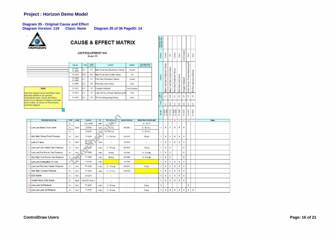
Diagram 35 - Original Cause and EffectDiagram Version: 119 Class: None Diagram 35 of 36 PageID: 14
Note
Here the original Cause and Effect chart has been pasted in as a picture.ControlDraw does Cause and Effect charts via a collection of objects and links and a matrix, as shown on the process overview diagram
2
Project : Horizon Demo Model
De m
o n stra
tion
ControlDraw Users Page: 16 of 21

Diagram 36 - SIL ResultsDiagram Version: 97 Class: None Diagram 36 of 36 PageID: 6
esdstuffPFD HRFESD1ESD2ESD3-1ESD3-2ESD3-3ESD3-4ESD3-5
Safety FunctionLow Low Steam Drum LevelHigh High Steam Drum Pressure PressureLow Low Fuel Gas PressureHigh High Fuel Gas PressureLow Low Pilot Gas PressureLoss of Combustion AirHigh High Furnace Pressure
PFD1.49-E-031.76-E-021.58E-03 6351.58E-03 6351.58E-03 6351.88E-03 5321.58E-03 635
HRF67060635635635532635
Calc SIL2122222
Req SIL0121222
RealTagU36.ESD01U36.ESD02U36.ESD05U36.ESD06U36.ESD08U36.ESD09U36.Effect XY-6367 XY-6369U36.Effect FC-0159U36.Effect XY-6364 XY-6366U36.Effect XY-6365U36.Effect XY-6370U36.Effect XY-6375U36.Effect XY-6373U36.ESD03U36.ESD04U36.ESD10U36.ESD11U36.ESD12U36.ESD13
PFD1.49E-031.76E-021.58E-031.58E-031.58E-031.58E-03
1.58E-031.58E-031.58E-031.58E-031.58E-031.58E-03
HRF Calc SIL222222
222222
Rec SIL222222
222222
UsertextLow Low Steam Drum LevelHigh High Steam Drum PressureLow Low Fuel Burner Gas PressureHigh High Fuel Burner Gas PressureLow Low Pilot Gas Header PressureHigh High Furnace PressureMain Fuel Gas Shutdown ValvesMain Fuel Gas Control ValvePilot Gas Shutdown ValvesPilot GasVentValveOxygen Analyzer De-EnergizedLube Oil Aux. Pump Interposing RelayFan Interposing RelayLoss of FlameLow Low Fuel Header Gas PressureBSD ButtonControl Room BSD ButtonLow Lube Oil PressureLow Low Lube Oil Pressure
Original pasted in for reference
Table from this model for class Safety Control Function (data not correct)
Project : Horizon Demo Model
De m
onstra
tion
ControlDraw Users Page: 17 of 21
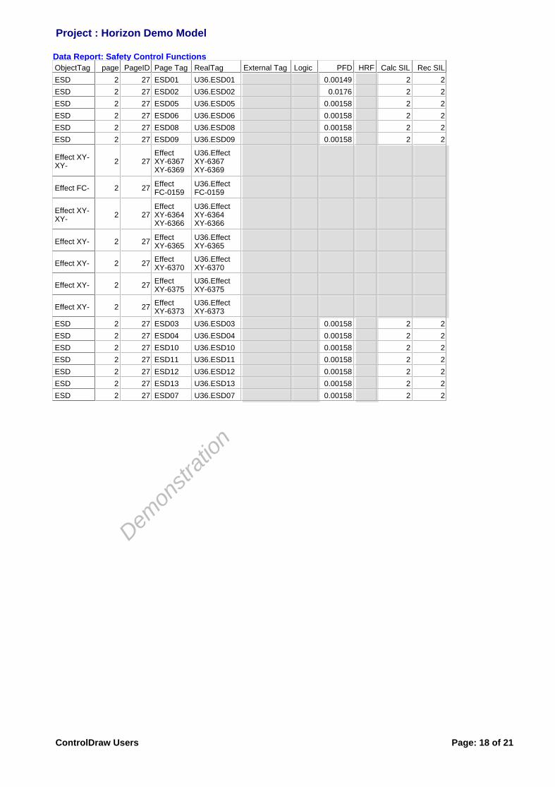
Data Report: Safety Control Functions
ObjectTag page PageID Page Tag RealTag External Tag Logic PFD HRF Calc SIL Rec SIL
ESD 2 27 ESD01 U36.ESD01 0.00149 2 2
ESD 2 27 ESD02 U36.ESD02 0.0176 2 2
ESD 2 27 ESD05 U36.ESD05 0.00158 2 2
ESD 2 27 ESD06 U36.ESD06 0.00158 2 2
ESD 2 27 ESD08 U36.ESD08 0.00158 2 2
ESD 2 27 ESD09 U36.ESD09 0.00158 2 2
Effect XY- XY-
2 27Effect XY-6367 XY-6369
U36.Effect XY-6367 XY-6369
Effect FC- 2 27Effect FC-0159
U36.Effect FC-0159
Effect XY- XY-
2 27Effect XY-6364 XY-6366
U36.Effect XY-6364 XY-6366
Effect XY- 2 27Effect XY-6365
U36.Effect XY-6365
Effect XY- 2 27Effect XY-6370
U36.Effect XY-6370
Effect XY- 2 27Effect XY-6375
U36.Effect XY-6375
Effect XY- 2 27Effect XY-6373
U36.Effect XY-6373
ESD 2 27 ESD03 U36.ESD03 0.00158 2 2
ESD 2 27 ESD04 U36.ESD04 0.00158 2 2
ESD 2 27 ESD10 U36.ESD10 0.00158 2 2
ESD 2 27 ESD11 U36.ESD11 0.00158 2 2
ESD 2 27 ESD12 U36.ESD12 0.00158 2 2
ESD 2 27 ESD13 U36.ESD13 0.00158 2 2
ESD 2 27 ESD07 U36.ESD07 0.00158 2 2
Project : Horizon Demo Model
De m
onstra
tion
ControlDraw Users Page: 18 of 21
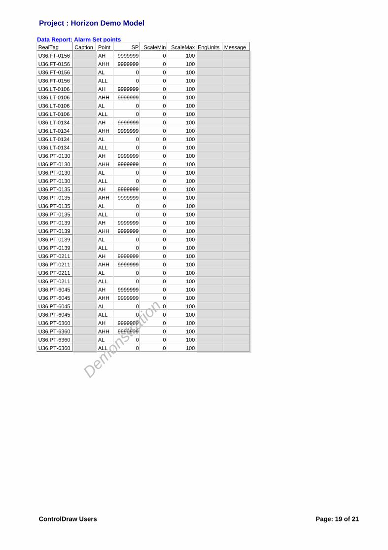
Data Report: Alarm Set points
RealTag Caption Point SP ScaleMin ScaleMax EngUnits Message
U36.FT-0156 AH 9999999 0 100
U36.FT-0156 AHH 9999999 0 100
U36.FT-0156 AL 0 0 100
U36.FT-0156 ALL 0 0 100
U36.LT-0106 AH 9999999 0 100
U36.LT-0106 AHH 9999999 0 100
U36.LT-0106 AL 0 0 100
U36.LT-0106 ALL 0 0 100
U36.LT-0134 AH 9999999 0 100
U36.LT-0134 AHH 9999999 0 100
U36.LT-0134 AL 0 0 100
U36.LT-0134 ALL 0 0 100
U36.PT-0130 AH 9999999 0 100
U36.PT-0130 AHH 9999999 0 100
U36.PT-0130 AL 0 0 100
U36.PT-0130 ALL 0 0 100
U36.PT-0135 AH 9999999 0 100
U36.PT-0135 AHH 9999999 0 100
U36.PT-0135 AL 0 0 100
U36.PT-0135 ALL 0 0 100
U36.PT-0139 AH 9999999 0 100
U36.PT-0139 AHH 9999999 0 100
U36.PT-0139 AL 0 0 100
U36.PT-0139 ALL 0 0 100
U36.PT-0211 AH 9999999 0 100
U36.PT-0211 AHH 9999999 0 100
U36.PT-0211 AL 0 0 100
U36.PT-0211 ALL 0 0 100
U36.PT-6045 AH 9999999 0 100
U36.PT-6045 AHH 9999999 0 100
U36.PT-6045 AL 0 0 100
U36.PT-6045 ALL 0 0 100
U36.PT-6360 AH 9999999 0 100
U36.PT-6360 AHH 9999999 0 100
U36.PT-6360 AL 0 0 100
U36.PT-6360 ALL 0 0 100
Project : Horizon Demo Model
De m
onstra
tion
ControlDraw Users Page: 19 of 21

Data Report: Control System IOList
ObjectTag page RealTag IO Type Node Card Channel
csDO 29 U36.UX-6035.DO
csDO 29 U36.UY-6056.DO
csDO 29 U36.UX-6357.DO
csDO 29 U36.UX-6358.DO
csDO 29 U36.UX-6359.DO
csDO 29 U36.XL-0216-R.DO
csDO 29 U36.XL-0216-S.DO
csDI 28 U36.LSLL-6046.DI
csAI 27 U36.LT-0106.AI 01 01 02
csAI 27 U36.LT-0134.AI 01 01
csAI 27 U36.PT-0130.AI 01 01
csDI 28 U36.BS-0138.DI
csDI 28 U36.BS-0137.DI
csDI 28 U36.HS-6116.DI
csAI 27 U36.PT-6045.AI 01 01
csAI 27 U36.PT-6360.AI 01 01
csAI 27 U36.FT-0156.AI 01 01
csAI 27 U36.PT-0139.AI 01 01
csAI 27 U36.PT-0135.AI 01 01
csAI 27 U36.PT-0211.AI 01 01
csDOSov 25 U36.XV-6367.DOSov
csDIClosed 25 U36.XV-6367.DIClosed
csDOSov 25 U36.XV-6369.DOSov
csDIClosed 25 U36.XV-6369.DIClosed
csDO 29 U36.FC-0159.DO
csDOSov 25 U36.XV-6366.DOSov
csDIClosed 25 U36.XV-6366.DIClosed
csDOSov 25 U36.XV-6364.DOSov
csDIClosed 25 U36.XV-6364.DIClosed
csDOSov 25 U36.XV-6365.DOSov
csDIClosed 25 U36.XV-6365.DIClosed
csDIOpen 25 U36.XV-6365.DIOpen
csDOSov 25 U36.XY-6370.DOSov
csDI 28 U36.PSL-0178.DI
csDO 29U36.Boiler Field startuppanel.XL-0002.DO
csDO 29U36.Boiler Field startuppanel.XL-0137.DO
csDI 28U36.Boiler Field startuppanel.HS-0130.DI
csDO 29U36.Boiler Field startuppanel.XL-0138.DO
csDI 28U36.Boiler Field startuppanel.HS-0135.DI
csDO 29U36.Boiler Field startuppanel.XL-6056.DO
csDI 28U36.Boiler Field startuppanel.HS-0156.DI
csDO 29U36.Boiler Field startuppanel.XL-6362.DO
csDO 29U36.Boiler Field startuppanel.XL-6363.DO
csDI 28U36.Boiler Field startuppanel.HS-6039.DI
csDI 28U36.Boiler Field startuppanel.HS-6041.DI
Project : Horizon Demo Model
De m
o n stra
tion
ControlDraw Users Page: 20 of 21
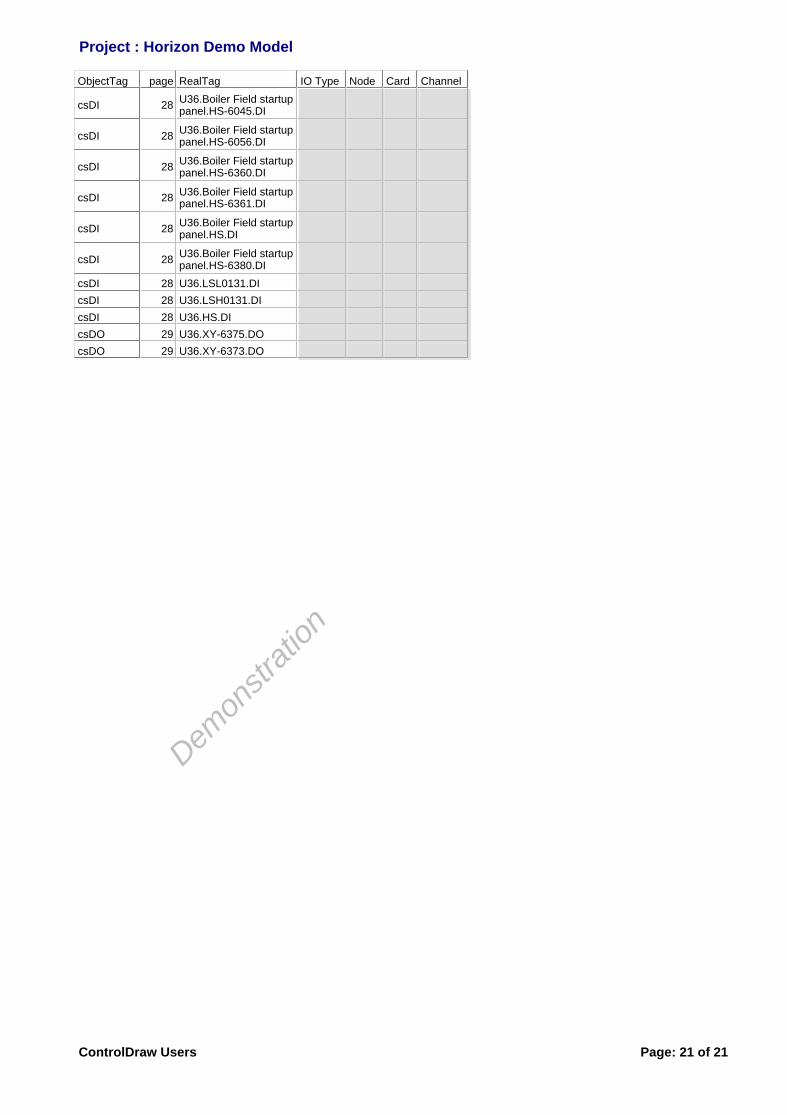
ObjectTag page RealTag IO Type Node Card Channel
csDI 28U36.Boiler Field startuppanel.HS-6045.DI
csDI 28U36.Boiler Field startuppanel.HS-6056.DI
csDI 28U36.Boiler Field startuppanel.HS-6360.DI
csDI 28U36.Boiler Field startuppanel.HS-6361.DI
csDI 28U36.Boiler Field startuppanel.HS.DI
csDI 28U36.Boiler Field startuppanel.HS-6380.DI
csDI 28 U36.LSL0131.DI
csDI 28 U36.LSH0131.DI
csDI 28 U36.HS.DI
csDO 29 U36.XY-6375.DO
csDO 29 U36.XY-6373.DO
Project : Horizon Demo Model
De m
onstra
tion
ControlDraw Users Page: 21 of 21