control system - nordsonemanuals.nordson.com/adhesives/3000/manuals/b1en0102.pdfcontrol system this...
TRANSCRIPT

� 2000 Nordson CorporationAll rights reserved
41-3000Issued 11/00
B1EN-01-[3M-CONTROL]-2
Part B, Section 1
Control System
This section covers the following unit configurations.
Model 3000
Voltage All
Pump All
Manifold All
Control MultiScan (3)

Control SystemB 1-0
� 2000 Nordson CorporationAll rights reserved
41-3000Issued 11/00
B1EN-01-[3M-CONTROL]-2

Control System B 1-1
� 2000 Nordson CorporationAll rights reserved
41-3000Issued 11/00
B1EN-01-[3M-CONTROL]-2
Section B 1Control System
WARNING: Allow only qualified personnel to perform thefollowing tasks. Follow the safety instructions in this documentand all other related documentation.
This section includes MultiScan control system troubleshootingprocedures and repair procedures. Obvious causes of problems, such asbroken wires, are generally not included in the troubleshootingprocedures. Refer to the Parts section for the part number of anycomponent that needs to be replaced. If you try all the suggestions inthis section and still cannot solve the problem, call your Nordsonrepresentative for assistance.
Refer to the Pump section for adhesive application and outputtroubleshooting procedures and repair procedures for the melter’s pump,motor (if present), and manifold assemblies. For hose or guntroubleshooting, refer to your hose or gun manual.
The following sections of this manual contain additional information onthe control system:
� Overview includes an overview of the control system.
� Installation includes procedures for making the parent machineinterlock (PMI) and fault output contact connections, connectingelectrical service, and setting up the control system for youroperation.
� Operation includes procedures for operating and monitoring thecontrol panel.
� Schematics includes a set of schematics for your system.
Refer to the Options section at the end of this manual for troubleshooting,repair, and parts information for the following options:
� Electric line filter� Input/output (I/O) board� Pressure dump� Low-level switch
1. Introduction

Control SystemB 1-2
� 2000 Nordson CorporationAll rights reserved
41-3000Issued 11/00
B1EN-01-[3M-CONTROL]-2
The MultiScan control system determines how your melter functions andthe temperatures at which the tank, grid (if applicable), hoses, and gunsoperate. The control system includes several printed circuit boards(hereafter referred to as boards) and other components that you shouldbe familiar with to safely troubleshoot and repair your melter.
See Figure B 1-1. The control system on all MultiScan melters includesthe control-end frame, the hose/gun control panels and boards, the maincontrol panel and boards, and the power modules and boards.
4130937A
3
1
5
4
2
6
7
Fig. B 1-1 Standard MultiScan Control System Components
1. Hose/gun control panels andboards
2. Main control panel3. Display board
4. Main control board5. Control-end frame
6. Hose/gun power modules7. Tank power module
2. Overview of the ControlSystem
Standard Components

Control System B 1-3
� 2000 Nordson CorporationAll rights reserved
41-3000Issued 11/00
B1EN-01-[3M-CONTROL]-2
The control system also includes any melter-specific components that arerequired for the melter to function as specified for a specific application.The presence of these components varies depending on theconfiguration of the melter. Refer to Table B 1-1. For an illustration ofthese components, refer to Control Assembly Parts in the Parts section.
Table B 1-1 Melter-Specific Control System Components
Type of Melter Melter-Specific Components
Grid melters � Grid power module
AC gear pump melters � Motor control board
� Motor control interface board
� Start capacitor
� Run capacitor
� Motor control coil
Manual DC gear pumpmelters
� Motor control board
� Motor drive board
� Motor control interface board
Key-to-line (KTL) DC gearpump melters
� Motor control board
� Motor drive board
� Motor control interface board
Motor and pressure control(MPC) DC gear pump melters
� Motor control board
� Motor drive board
� Motor control interface board
� Pressure control interface boardwith voltage-to-current (V-to-I)board
� Pressure transducer
400 VAC melters � Transformer (with surge guards)
� Over-voltage protection board
� 400 VAC tank board
These troubleshooting tables describe the kinds of control systemproblems you may encounter and provide corrective actions for handlingthose problems. When necessary, the tables refer to more detailedtroubleshooting procedures. Refer to the appropriate troubleshootingtable for the type of problem you are experiencing:
� Melter Not Powering On� Circuit Breaker Trips or Will Not Stay On� Zone Not Heating� Control System Indicating a Fault� KTL or MPC Not Operating Properly
Melter-Specific Components
3. Troubleshooting Tables

Control SystemB 1-4
� 2000 Nordson CorporationAll rights reserved
41-3000Issued 11/00
B1EN-01-[3M-CONTROL]-2
The electrical enclosure must be opened before you can proceed withmany of the procedures in this section. Follow this procedure wheneveryou are instructed to open or close the electrical enclosure.
Swing-Open Melters
1. Place the melter circuit breaker in the OFF position.
2. See Figure B 1-2. To open the the electrical enclosure:
a. Remove the electrical enclosure lid and disconnect the groundwire.
b. Loosen the two captive screws near the top of melter (on eitherside of the control-end frame) and carefully lower the frame.
3. To close the electrical enclosure:
a. Carefully raise the control-end frame and secure it with thecaptive screws.
b. Reconnect any ground wires that were disconnected.
c. Reinstall and secure the electrical enclosure lid.
41310025A
1
3
2
Fig. B 1-2 Opening the Electrical Enclosure (swing-open melters)
1. Electrical enclosure lid2. Captive screw
3. Control-end frame
Opening and Closing theElectrical Enclosure
Control System B 1-5
� 2000 Nordson CorporationAll rights reserved
41-3000Issued 11/00
B1EN-01-[3M-CONTROL]-2
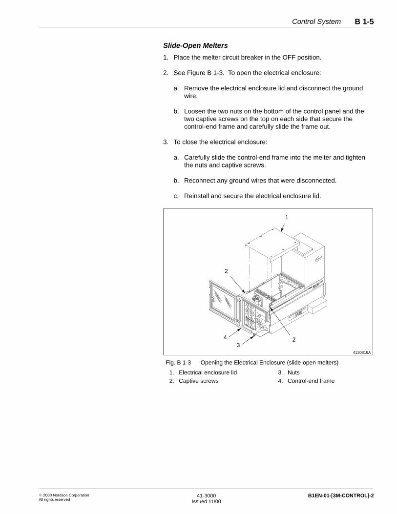
Slide-Open Melters
1. Place the melter circuit breaker in the OFF position.
2. See Figure B 1-3. To open the electrical enclosure:
a. Remove the electrical enclosure lid and disconnect the groundwire.
b. Loosen the two nuts on the bottom of the control panel and thetwo captive screws on the top on each side that secure thecontrol-end frame and carefully slide the frame out.
3. To close the electrical enclosure:
a. Carefully slide the control-end frame into the melter and tightenthe nuts and captive screws.
b. Reconnect any ground wires that were disconnected.
c. Reinstall and secure the electrical enclosure lid.
4130818A
1
2
324
Fig. B 1-3 Opening the Electrical Enclosure (slide-open melters)
1. Electrical enclosure lid2. Captive screws
3. Nuts4. Control-end frame

Control SystemB 1-6
� 2000 Nordson CorporationAll rights reserved
41-3000Issued 11/00
B1EN-01-[3M-CONTROL]-2
If your melter will not power on, use this troubleshooting table.
WARNING: Risk of electrical shock. Failure to observeelectrical safety procedures may result in equipment damage,personal injury, or death. Allow only qualified personnel toperform electrical troubleshooting. Observe all high voltageindicators.
Problem Possible Cause Corrective Action
Circuit breaker in ONposition but melter will notturn on
No input power Make sure the power is turned on atyour branch circuit disconnect switchand that you are supplying the propervoltage to the melter. If necessary, referto Making the Electrical ServiceConnections in the Installation section.
Blown fuse on main control board Check the two 1 amp fuses on the lowerpart of the main control board forcontinuity. Replace if necessary.
Failed circuit breaker Check the voltage at TB1 (located onthe center frame) and at TB2 (locatedunder the tank power module). If thereis sufficient voltage between each leg ofservice at TB1 and little or no voltagebetween wires 4 and 5 or wires 5 and 6at TB2, replace the circuit breaker.Refer to Replacing the Circuit Breaker inRepair Procedures.
400 VAC 3∅ melters only: defectivesurge guard
Check the surge guard. Refer toChecking a Surge Guard inTroubleshooting Procedures
400 VAC 3∅melters only: defectivetransformer
Check the transformer. Refer toChecking the Transformer inTroubleshooting Procedures.
Melter Not Powering On

Control System B 1-7
� 2000 Nordson CorporationAll rights reserved
41-3000Issued 11/00
B1EN-01-[3M-CONTROL]-2
If the circuit breaker trips off or will not stay on, use this troubleshootingtable.
WARNING: Risk of electrical shock. Failure to observeelectrical safety procedures may result in equipment damage,personal injury, or death. Allow only qualified personnel toperform electrical troubleshooting. Observe all high voltageindicators.
Problem Possible Cause Corrective Action
1. Circuit breaker tripsrepeatedly (no faultcondition indicated)
Tank or grid overtemperaturethermostat tripped circuit breaker
Disconnect the overtemperaturethermostat (close-on-rise). If the circuitbreaker holds when the thermostat isdisconnected, replace the thermostat.Do not operate the melter unless thethermostat is connected. Refer toReplacing a Tank Thermostat or RTD.
Failed circuit breaker or failedshutdown relay on main control board
Disconnect and lock out power to melter.Disconnect wire 7 on the back of thecircuit breaker and wrap the terminal onthe end of the wire with electrical tape.Restore power to the melter. Turn thecircuit breaker on. If the circuit breakerdoes not hold, replace the circuitbreaker. If the circuit breaker holds,replace the main control board. Refer toReplacing the Circuit Breaker orReplacing a Control System Componentin Repair Procedures.
Overcurrent or short circuit Visually check the wiring inside theelectrical enclosure. Look for incorrectconnections or loose or crossed wires.Check all circuits for a line-to-line orline-to-ground short.
Continued on next page
Circuit Breaker Trips or WillNot Stay On

Control SystemB 1-8
� 2000 Nordson CorporationAll rights reserved
41-3000Issued 11/00
B1EN-01-[3M-CONTROL]-2
Problem Possible Cause Corrective Action
2. Circuit breaker tripsintermittently (no faultcondition indicated)
Electrical noise from other equipmentin area
Check for electrical noise generated byother equipment in the area. Othermotor drives are often the source of theelectrical noise. Make sure the melterand the parent machine are on the sameground plane. Check the continuitybetween the frame of the melter and theframe of the parent machine. If there isno continuity or if there is highresistance, electrically ground the melterto the parent machine using as short alength of braided cable as possible.
3. Green lights undertemperature control dialsflicker rapidly for severalseconds and circuitbreaker trips (no faultcondition indicated andno temperature displayedin digital readout)
Failed microprocessor (watchdogfault)
Replace the main control board.
Circuit Breaker Trips or WillNot Stay On (contd.)

Control System B 1-9
� 2000 Nordson CorporationAll rights reserved
41-3000Issued 11/00
B1EN-01-[3M-CONTROL]-2
If a tank, grid, hose, or gun does not heat, use this troubleshooting table.
WARNING: Risk of electrical shock. Failure to observeelectrical safety procedures may result in equipment damage,personal injury, or death. Allow only qualified personnel toperform electrical troubleshooting. Observe all high voltageindicators.
Problem Possible Cause Corrective Action
Tank, grid, hose, or gundoes not heat orunderheats
Zone turned off or zone temperaturesetpoint too low
Make sure the zone is turned on bysetting the zone’s temperature controldial to the desired operating temperaturesetpoint. Make sure the temperaturesetpoint is high enough.
Insufficient input voltage Make sure you are supplying the propervoltage to the melter. Refer to Makingthe Electrical Service Connections in theInstallation Section.
Blown fuse on power module Remove the electrical enclosure lid andexamine the red control LED and theheater power neon on the power modulefor the nonheating component. If thered control LED is on and the neon isoff, check the continuity of the fuses onthe power module. If a fuse is open,replace the fuse. If a fuse is okay,replace the power module. Refer toReplacing a Control System Componentin Repair Procedures.
Continued on next page
Zone Not Heating

Control SystemB 1-10
� 2000 Nordson CorporationAll rights reserved
41-3000Issued 11/00
B1EN-01-[3M-CONTROL]-2
Problem Possible Cause Corrective Action
Tank, grid, hose, or gundoes not heat orunderheats (contd.)
High resistance on heater circuitcaused by loose or oxidized heaterconnection or failed component
Remove the electrical enclosure lid andexamine the red control LED and theheater power neon on the power modulefor the nonheating component. If bothlights are on, check all connections tothe heater circuit, including hose andgun plugs. Tighten loose connections.If the connections are okay, replace theheater or defective component. Toverify that a heater has the correctresistance, refer to Note A and use thewiring diagrams in the Schematicssection. Refer to the gun manual forinstructions on replacing a gun heater.You cannot replace a hose heater or atank heater—you must replace the hoseor tank. Refer to the Tank section forprocedures on tank replacement.
RTD circuit resistance high Remove the electrical enclosure lid andexamine the red control LED and theheater power neon on the power modulefor the non-heating component. If thered control LED is off and the neon isoff, check the resistance on the RTDcircuit for that zone. Refer to Checkingan RTD or RTD Circuit inTroubleshooting Procedures.
Failed ribbon cable in the circuit ofthe problem zone
Remove the electrical enclosure lid andexamine the red control LED and theheater power neon on the power modulefor the nonheating component. If thered control LED is off, check the ribboncable. Refer to Checking a RibbonCable in Troubleshooting Procedures.Replace the ribbon cable if it isdefective. If the ribbon cable is okay,replace the main control board and thedisplay board.
NOTE A: To determine what the resistance of a tank or grid heater should be, refer to Table B 1-2. Todetermine what the resistance of a hose or gun heater should be, use the following formula:V2 ÷ W= R (where V=voltage, W=wattage, and R=resistance). To determine the voltage and wattageof a gun heater, look at the gun identification plate or the heater cartridge. To determine the voltageand wattage of a hose heater, look at the hose tag.
Zone Not Heating (contd.)

Control System B 1-11
� 2000 Nordson CorporationAll rights reserved
41-3000Issued 11/00
B1EN-01-[3M-CONTROL]-2
Table B 1-2 Heater Resistance Data for the Tank, Grid, and Reservoir
Melter Component Resistance
3100 Tank 28.15–32.85
3400 Tank 23.93–27.92
3500 Tank 17.09–19.94
3700 Tank 12.60–14.69
3830 Tank 19.94–23.27
3860 Tank 12.60–14.69
3890 Tank 12.60–14.69
3930 Reservoir 25.19–129.39
Grid 25.86–30.18
3960 Reservoir 17.09–19.94
Grid 11.96–13.96

Control SystemB 1-12
� 2000 Nordson CorporationAll rights reserved
41-3000Issued 11/00
B1EN-01-[3M-CONTROL]-2
See Figure B 1-4. When a tank, grid, hose, or gun fault occurs,
� the red light next to the dial for the faulted zone turns on
� the OPEN SENSOR, SHORTED SENSOR, orOVERTEMPERATURE light in the zone status area turns on
� the SYSTEM FAULT light in the system status area turns on andthe red FAULT light by the circuit breaker turns on
� the melter shuts down after a two-minute time delay
When a fault occurs in more than one zone, the faults display one at atime in sequence. The SYSTEM FAULT light in the system status arearemains on as long as there is a fault in any zone.
After the two-minute time delay elapses, the melter will turn off. You canreset the circuit breaker immediately to obtain an additional two minutesof troubleshooting time. This may be repeated any number of timesunless the temperature of the tank or grid wall reaches 260 °C (500 °F).When the tank/grid wall temperature exceeds 260 °C (500 °F), thetank/grid overtemperature thermostat closes, causing the circuit breakerto trip. The circuit breaker cannot be reset until the tank/grid walltemperature falls below 260 °C (500 °F).
NOTE: Each heated component (each hose, each gun, the tank, and thegrid) is referred to as a heated zone, or zone. Zones may also bereferred to as channels.
4130897A
����������
�������
��������� ���
���������
����������
������������
�����������
34 2
1
Fig. B 1-4 Zone Status Lights and Temperature Control Dial Fault Lights
1. Zone status area lights2. Tank fault light
3. Gun fault light4. Hose fault light
Control System Indicating aFault

Control System B 1-13
� 2000 Nordson CorporationAll rights reserved
41-3000Issued 11/00
B1EN-01-[3M-CONTROL]-2
WARNING: Risk of electrical shock. Failure to observeelectrical safety procedures may result in equipment damage,personal injury, or death. Allow only qualified personnel toperform electrical troubleshooting. Observe all high voltageindicators.
Problem Possible Cause Corrective Action
1. SYSTEM FAULT, zonefault, and OPENSENSOR lights turn on(open RTD fault)
Zone turned on but no hose or gunconnected to that zone
Connect a hose or gun to the zone orset the temperature control dial for theunused zone to OFF. This will disablethe zone.
Loose hose or gun cordsetconnection
Make sure all hose and gun cordsetconnections are tight.
Open RTD circuit, open RTD, orfailed ribbon cable between powermodule and main control board
Check the RTD and the RTD circuit forthe problem zone. Refer to Checking anRTD or RTD Circuit in TroubleshootingProcedures. Check the ribbon cable forthe problem zone. Refer to Checking aRibbon Cable in TroubleshootingProcedures.
2. SYSTEM FAULT, zonefault, and SHORTEDSENSOR lights turn on(shorted RTD fault)
Shorted RTD, RTD circuit, or ribboncable in the problem zone
Check the RTD for a shorted condition.If the RTD is defective, replace it. If theRTD is okay, check the wiring andribbon cable for a shorted condition.
3. SYSTEM FAULT, zonefault, andOVERTEMPERATURElights turn on(overtemperature fault)
Overtemperature setpoint too low Make sure the overtemperature setpointis not below the operating temperaturesetpoint. Refer to Changing theOvertemperature Setpoint in theInstallation section.
Shorted power module Check for a shorted power module.Observe the red control LED and thepower neon on the power module. If thered control LED is off and the powerneon is on, replace the power module(the switching component on the powermodule board is not turning off). Referto Checking the Power Module Lights inTroubleshooting Procedures.
Continued on next page

Control SystemB 1-14
� 2000 Nordson CorporationAll rights reserved
41-3000Issued 11/00
B1EN-01-[3M-CONTROL]-2
Problem Possible Cause Corrective Action
3. SYSTEM FAULT, zonefault, andOVERTEMPERATURElights turn on(overtemperature fault)(contd.)
Low reference voltage on the maincontrol board
Observe the red control LED and thepower neon on the power module for theproblem zone. If the red control LED,the power neon, and theOVERTEMPERATURE light are on, thenthe reference voltage on the maincontrol board is probably low. If thesystem has an I/O board or an encoder,disconnect the ribbon cable between theI/O board and the main control board ordisconnect the cable between theencoder and the motor control interfaceboard. If this corrects the problem,replace the I/O board or the ribboncable. If the problem persists, replacethe main control board.
4. SYSTEM FAULT andMOTOR FAULT lightsturn on (motor fault) (DCgear pump melters only)
Motor overloaded Check for conditions that could causethe motor to overheat, such as coldadhesive, a broken fan, or a bent shaft.Check for loose connections inside themotor junction box. Let the motor cooldown and restart the melter. If the motorcontinues to overheat, replace themotor.
Failed motor overtemperaturethermostat
Let the motor cool down and check thethermostat for continuity at wires 39 and32 in the motor junction box. If there isno continuity, replace the motor.
Jumper shunts on motor controlinterface boards improperly set
Check the jumper shunts for thethermostat on the motor control interfaceboards. See Figure B 1-11.
5. MAX speed light turnson (KTL andMPC melters)
Line speed exceeds maximumpotentiometer setting
Slow down the production line speed oradjust the KTL or MPC setup. Refer toKTL Setup or MPC Setup in theInstallation section.
Control System Indicating aFault (contd.)

Control System B 1-15
� 2000 Nordson CorporationAll rights reserved
41-3000Issued 11/00
B1EN-01-[3M-CONTROL]-2
If the KTL or MPC is not operating properly, use this troubleshootingtable.
Problem Possible Cause Corrective Action
Bead size changes whenline speed changes
MANUAL mode selected at thecontrol panel or through I/O boardremote function
Make sure the MANUAL/AUTO switch isin the AUTO position and that thefunction has not been disabled throughthe I/O board.
KTL or MPC improperly calibrated Refer to KTL Setup or MPC Setup in theInstallation section.
MPC melters only: Air-pilotedpressure control valve sticking
Replace the air-piloted pressure controlvalve.
Pump not producing enough volume Increase the motor speed. Check forbroken O-rings on the pump crossovertube and on the pressure control valveand replace them. Replace the pump ifpump wear is suspected. Refer to thePump section for pump disassembly andreassembly procedures.
Use these procedures as directed in the troubleshooting tables to furthertroubleshoot control system problems.
Follow this procedure to check a surge guard on a 400 VAC 3∅ melter.
1. Turn off the melter, disconnect and lock out electrical power to themelter at the branch circuit disconnect switch, and disconnect andlock out electrical power supplied through any I/O wiring.
2. Open the electrical enclosure. Refer to Opening and Closing theElectrical Enclosure.
WARNING: Risk of burns. Surge guards can reachtemperatures as high as 81 �C (177 �F). Wear heat-protectivegloves and do not touch the surge guards.
KTL or MPC Not OperatingProperly
4. TroubleshootingProcedures
Checking a Surge Guard

Control SystemB 1-16
� 2000 Nordson CorporationAll rights reserved
41-3000Issued 11/00
B1EN-01-[3M-CONTROL]-2
3. Connect an ohmmeter set on the highest resistance scale across thesurge guard.
NOTE: The melter has two surge guards.
4. If you measure infinite resistance, the surge guard is defective. Referto Replacing a Surge Guard in Repair Procedures.
Follow this procedure to check the transformer on a 400 VAC 3∅ melter.
1. Turn off the melter, disconnect and lock out electrical power to themelter at the branch circuit disconnect switch, and disconnect andlock out electrical power supplied through any I/O wiring.
2. Open the electrical enclosure. Refer to Opening and Closing theElectrical Enclosure.
3. See Figure B 1-5. Check for continuity across the primary andsecondary transformer windings. If you do not measure continuity,replace the transformer.
400 VACPRIMARY
230 VACSECONDARY
4
3
2
1
1
3 4
2
4130855A
Fig. B 1-5 Transformer Wiring Diagram
Checking a Surge Guard (contd.)
Checking the Transformer

Control System B 1-17
� 2000 Nordson CorporationAll rights reserved
41-3000Issued 11/00
B1EN-01-[3M-CONTROL]-2
Follow this procedure to check an RTD or RTD circuit.
NOTE: If the faulted zone is a hose or a gun, you can disconnect thehose or gun at that zone and connect a hose or gun that is known to begood, or you can move the faulted hose or gun to another connection. Ifthe fault disappears or follows the hose or gun, then you will know thatthe problem is in the hose or gun, not inside the melter. As an alternativeto using this procedure, refer to your hose or gun manual for instructionson checking the hose or gun RTD and replacing the RTD.
1. Turn off the melter, disconnect and lock out electrical power to themelter at the branch circuit disconnect switch, and disconnect andlock out electrical power supplied through any I/O wiring.
2. Open the electrical enclosure. Refer to Opening and Closing theElectrical Enclosure.
3. Disconnect the two pin plug between the tank RTD and the maincontrol board.
4. Check the RTD resistance. To check the tank and grid RTD, use asurface-temperature sensing device, such as a pyrometer, tomeasure the temperature of the heated zone at or near the RTD.Then measure the RTD’s resistance.
NOTE: If the faulted zone is a hose or gun, measure the RTDresistance at the hose or gun electrical plug. Refer to your hose orgun manual for a diagram of the electrical plug and for procedures forchecking RTD resistance. Because the core elements of a hose arenot accessible, the easiest method to check the actual temperature ofa hose is to secure the end of the hose over a waste container. Thenuse a pyrometer with an immersion probe and measure thetemperature of the adhesive as it is being discarded into the wastecontainer.
5. Compare the RTD’s temperature and resistance reading to thenormal resistance range shown in Figure B 1-6.
� If the RTD resistance is significantly outside the normal range,replace the RTD. If a hose RTD is defective, you must replacethe hose. To replace a gun RTD, refer to your gun manual. Toreplace a tank RTD, refer to Replacing an RTD or a Thermostat inRepair Procedures.
� If the RTD resistance is within the normal range, go to the nextstep.
NOTE: For hose resistance data, refer to your hose manual.
Checking an RTD or RTDCircuit

Control SystemB 1-18
� 2000 Nordson CorporationAll rights reserved
41-3000Issued 11/00
B1EN-01-[3M-CONTROL]-2
6. Check the continuity of the RTD circuit by measuring the RTDresistance at other points in the circuit. Refer to the Schematicssection. Note that intermittent connections are the most difficult totroubleshoot since they are not always evident during continuitytesting.
7. If you find a continuity problem in the RTD circuit, replace or repairthe defective component as appropriate. If you do not find acontinuity problem, replace the main control board. Refer toReplacing the Main Control Board in Repair Procedures.
(50 ) (90 ) (290 )�F
5940833
�F (130 ) �C54
�F �F�C�C�C
(170 )�C �C77 99 121 143 166 188 210 232�C �C �C
�F (210 )�F (250 )�F (370 )�F (410 )�F (450 )�F(330 )�F
160
360
340
320
300
280
260
240
220
200
180
140
120
RT
D R
ES
ISTA
NC
E IN
OH
MS
�C32 �C10
RTD TEMPERATURE
Fig. B 1-6 RTD Resistance vs. RTD Temperature
Checking an RTD or RTDCircuit (contd.)

Control System B 1-19
� 2000 Nordson CorporationAll rights reserved
41-3000Issued 11/00
B1EN-01-[3M-CONTROL]-2
Follow this procedure to check the continuity of a ribbon cable.
1. Turn off the melter, disconnect and lock out electrical power to themelter at the branch circuit disconnect switch, and disconnect andlock out electrical power supplied through any I/O wiring.
2. Open the electrical enclosure. Refer to Opening and Closing theElectrical Enclosure.
3. Disconnect both ends of the suspect ribbon cable.
4. Place a small-gauge solid wire into corresponding positions on theconnectors at each end of the ribbon cable. Pin 1 is usually indicatedby an arrow or some other distinguishing mark on the connectorhousing.
5. Check the resistance. The resistance should be less than 1 ohm ateach position. Flex the cable to check for a possible intermittent opencircuit. For a complete test, check for continuity between eachposition and its adjacent positions at each end of the ribbon cable. Ifcontinuity is detected between any two adjacent positions, then theribbon cable is defective.
NOTE: A ribbon cable may pass a continuity test but still be defectivedue to an undetected intermittent open circuit. You may need afast-responding meter to detect an intermittent open circuit.
Checking a Ribbon Cable

Control SystemB 1-20
� 2000 Nordson CorporationAll rights reserved
41-3000Issued 11/00
B1EN-01-[3M-CONTROL]-2
The power modules supply power to a hose, gun, tank, or grid heaterwhen a low-voltage signal is received from the main control board. Therecan be up to three four-channel power modules for the hose and gunheaters. There is a one-channel power module for the tank heater.There is also a second one-channel power module for the grid on aSeries 3900 melter. Each power module has diagnostic lights to assistyou in troubleshooting temperature problems. Follow this procedure tocheck the power module lights.
WARNING: Risk of electrical shock. Failure to observeelectrical safety procedures may result in equipment damage,personal injury, or death. Allow only qualified personnel toperform electrical troubleshooting. Observe all high voltageindicators.
1. Open the electrical enclosure. Refer to Opening and Closing theElectrical Enclosure.
2. Observe the power module for the problem zone. See Figure B 1-7and refer to Table B 1-3 to interpret the power module lights.
Table B 1-3 Checking the Power Module Lights
Zone FaultLight on
Control Panel
Red ControlLED on Power
Module
Heater PowerNeon on Power
ModuleCondition
Off Off Off The zone is above the temperature setpoint and iscooling.
Off On On The zone is below the temperature setpoint and isheating, or, if the temperature does not increase, theheater circuit is open.
Off Flashing Flashing The zone is at the temperature setpoint.
Off On Off The power circuit to the heater is open. Check the fuses.
Off Off On The power circuit to the heater is not turning off. Replacethe power module.
NOTE: This is a normal indication for a disconnectedhose or gun zone.
On On On The RTD is shorted.
On Off Off The RTD is open.
On Off On There is an overtemperature condition because thepower module is shorted on. A four-channel powermodule will also display this sequence of lights if thezone is turned on but the hose or gun is disconnectedelectrically.
Checking the Power ModuleLights

Control System B 1-21
� 2000 Nordson CorporationAll rights reserved
41-3000Issued 11/00
B1EN-01-[3M-CONTROL]-2
4130898A
TANK LED
TANK NEON
GUN 1 LED AND NEON
HOSE 1 LED AND NEON
GUN 2 LED AND NEON
HOSE 2 LED AND NEON
GUN 3 LED AND NEON
HOSE 3 LED AND NEON
GUN 4 LED AND NEON
HOSE 4 LED AND NEON
GUN 5 LED AND NEON
HOSE 5 LED AND NEON
GUN 6 LED AND NEON
HOSE 6 LED AND NEON
Fig. B 1-7 Location of Indicator Lights on Power Modules
Follow this procedure to check the MPC pressure control only after youhave made sure that your MPC system is properly calibrated inaccordance with MPC Setup in the Installation section.
1. If the green light near the pressure control dial is on, check the airpressure at the air-piloted pressure control valve.
a. Disconnect the air line and connect an air pressure gauge to theline. Check for increasing/decreasing air pressure as the linespeed changes.
� If the pressure varies, check for a clogged, binding, ordamaged pressure control valve. Refer to Replacing thePressure Control Valve in the Tank and Manifold section asnecessary.
� If the pressure does not vary, continue to the next step.
Checking the MPC PressureControl

Control SystemB 1-22
� 2000 Nordson CorporationAll rights reserved
41-3000Issued 11/00
B1EN-01-[3M-CONTROL]-2
b. Check the air supply to the transducer.
� If the air supply is insufficient, correct the air supply problem.
� If the air supply is okay, continue to the next step.
c. Use a scope or frequency counter to check the encoder signal.
� If there is no encoder signal, repair or replace the encoder.
� If the encoder signal is okay, continue to the next step.
d. Check the 4–20 mA output signal at J5-1 and J5-2 by putting acurrent meter in series with the transducer. Make sure the currentvaries as the line speed varies.
� If the 4–20 mA signal is okay, replace the transducer.
� If the 4–20 mA signal is not okay, continue to the next step.
e. Check JMP 1 on the interface board. Jumper should connect pins1 and 2. Correct setting if not correct.
f. Check for DC voltage at J2-1 and J2-4.
� If the voltage is 0–2.5 VDC, replace the V-to-I board.
� If the voltage is not 0–2.5 VDC, continue to the next step.
g. Check the ribbon cable between the PCB-11 motor control boardand the PCB-15 pressure control interface board.
� If the ribbon cable is okay, replace the PCB-15 pressurecontrol interface board.
� If the ribbon cable is not okay, replace the ribbon cable. Referas needed to Replacing the Pressure Control Valve in theTank and Manifold section, Replacing the Transducer inRepair Procedures in this section, or Replacing a ControlSystem Component in Repair Procedures in this section.
Checking the MPC PressureControl (contd.)

Control System B 1-23
� 2000 Nordson CorporationAll rights reserved
41-3000Issued 11/00
B1EN-01-[3M-CONTROL]-2
2. If the green light near the pressure control dial is off, restart the MPCusing the motor on/off switch (the READY light must be on).
a. Check the green pressure control on light again.
� If the light turns on, recheck the bead size and the line speedtracking.
� If the light does not turn on, continue to the next step.
b. Check fuses F1 and F2 on the PCB-15 pressure control interfaceboard.
� If the fuses are open, replace them.
� If the fuses are okay, continue to the next step.
c. If the melter has an I/O board, make sure there is no maintainedmotor stop signal to the I/O board.
d. Check the voltage between fuses F1 and F2 on the PCB-15pressure control interface board.
� If there is no voltage, correct the power supply problem to thepressure control board.
� If the voltage is okay, replace the PCB-15 pressure controlinterface board. Refer to Replacing a Control SystemComponent in Repair Procedures.

Control SystemB 1-24
� 2000 Nordson CorporationAll rights reserved
41-3000Issued 11/00
B1EN-01-[3M-CONTROL]-2
Troubleshooting procedures may identify failed components. Use theserepair procedures to replace failed components. Refer to the parts listsat the end of this section to locate and order replacement parts andservice kits. You can also use the parts lists drawings as a guide as youperform the following repair procedures.
WARNING: Risk of electrical shock. Failure to observeelectrical safety procedures may result in equipment damage,personal injury, or death. Allow only qualified personnel toperform electrical repairs. Observe all high voltage indicators.
Use this procedure to replace a defective surge guard on 400 VAC 3∅melters.
1. Turn off the melter, disconnect and lock out electrical power to themelter at the branch circuit disconnect switch, and disconnect andlock out electrical power supplied through any I/O wiring.
2. Open the electrical enclosure. Refer to Opening and Closing theElectrical Enclosure.
WARNING: Risk of burns. Surge guards can reachtemperatures as high as 81 �C (177 �F). Wear heat-protectivegloves.
CAUTION: Risk of equipment damage. Make sure surgeguards do not contact each other or any other component withinthe enclosure. Maintain 10-mm spacing.
3. See Figure B 1-8. Disconnect the defective surge guard and replaceit with a new one. Position the surge guards so they do not contacteach other or any other component within the enclosure.
5. Repair Procedures
Replacing a Surge Guard

Control System B 1-25
� 2000 Nordson CorporationAll rights reserved
41-3000Issued 11/00
B1EN-01-[3M-CONTROL]-2
4601105
2
1
1
Fig. B 1-8 Surge Guards
1. Surge guard 2. Transformer
4. Close and secure the electrical enclosure. Refer to Opening andClosing the Electrical Enclosure.
Follow this procedure to replace the tank RTD or thermostat.
Preparation
1. Turn off the melter, disconnect and lock out electrical power to themelter at the branch circuit disconnect switch, and disconnect andlock out electrical power supplied through any I/O wiring.
2. Remove the electrical enclosure lid and disconnect the ground wire.
3. Remove the hopper and drive covers.
4. Remove the front cover and disconnect the ground wire.
5. Locate the tank RTD and overtemperature thermostat behind thecutaway in the tank insulation (above the manifold filter).
Replacing the Tank RTD orThermostat

Control SystemB 1-26
� 2000 Nordson CorporationAll rights reserved
41-3000Issued 11/00
B1EN-01-[3M-CONTROL]-2
RTD Replacement
1. Disconnect the RTD plug.
2. See Figure B 1-9. Follow these steps to replace the RTD:
a. Remove the RTD retainer plate (2) and then remove the RTD (1).
b. Coat the new RTD with thermal compound and insert it into thetank.
c. Reinstall the RTD retainer plate in the orientation shown inFigure B 1-9.
3. Reposition the insulation over the tank RTD and thermostat. It is notnecessary to tape the insulation, but if you do be sure to usehigh-temperature tape.
4. Connect the RTD plug.
4103516B
ÎÎÎÎÎÎÎÎÎÎÎÎÎÎÎ
ÏÏÏÏÏÏÏÏÏÏÏÏ
ÎÎÎÎÎÎÎÎÎÎÎÎÎÎÎÎÎÎÎÎ
ÎÎ
ÎÎÎÎÎÎÎÎÎÎÎÎÎÎÎÎÎÎ
1
2
Fig. B 1-9 Replacing the Tank RTD
1. RTD 2. Retainer plate

Control System B 1-27
� 2000 Nordson CorporationAll rights reserved
41-3000Issued 11/00
B1EN-01-[3M-CONTROL]-2
Thermostat Replacement
1. Disconnect the thermostat plug.
2. See Figure B 1-10. Follow these steps to replace the thermostat:
a. Push back the rubber insulator and remove the screws thatsecure the thermostat to the tank.
b. Remove the old thermostat and install a new one.
c. Push the rubber insulator back over the thermostat.
4103515A
ÎÎÎÎÎÎÎÎÎÎÎÎ
ÏÏÏÏÏÏÏÏÏÏÏÏÏÏÏÏÏÏÏÏ
ÎÎÎÎÎÎÎÎÎÎÎÎÎÎÎÎÎÎÎÎ
ÎÎ
ÎÎÎÎÎÎÎÎÎÎÎÎÎÎÎÎÎÎÎÎ
Fig. B 1-10 Replacing the Tank Thermostat
3. Reposition the insulation over the tank RTD and thermostat. It is notnecessary to tape the insulation, but if you do be sure to usehigh-temperature tape.
4. Connect the thermostat plug.
System Restoration
1. Reinstall the hopper and drive covers.
2. Reinstall the front cover and attach the ground wire.
3. Reinstall the electrical enclosure lid and attach the ground wire.
4. Restore power to the melter and resume normal operation.
Control SystemB 1-28
� 2000 Nordson CorporationAll rights reserved
41-3000Issued 11/00
B1EN-01-[3M-CONTROL]-2
Follow this procedure to replace any control system component. Thecontrol system components include control panels, boards, and powermodules.
1. Turn off the melter, disconnect and lock out electrical power to themelter at the branch circuit disconnect switch, and disconnect andlock out electrical power supplied through any I/O wiring.
2. Open the electrical enclosure. Refer to Opening and Closing theElectrical Enclosure.
3. Attach a static wrist strap from your wrist to the ground stud on thebase of the melter.
4. Refer to the illustrations in Control Assembly Parts in the Partssection. Disconnect all ribbon cables and other connections from thecomponent you are replacing. Mark or label the connections for laterreference.
5. Remove the hardware that secures the component; then carefullyremove the component.
6. Install the new component using the hardware you removed earlier.
7. Connect all ribbon cables and other connections to the newcomponent.
8. If you are installing a main control board, make sure theovertemperature thermostat jumper is in the correct position and thatthe time delay switches are set properly. Refer to Changing theOvertemperature Setpoint and Changing the Time Delay Setting inthe Installation section.
9. If you are replacing the motor or pressure control interface board orthe voltage-to-current board, make sure the jumper shunts are set asshown in Figure B 1-11.
10. Close the electrical enclosure. Refer to Opening and Closing theElectrical Enclosure.
11. Restore power to the melter and resume normal operation.
Replacing a Control SystemComponent

Control System B 1-29
� 2000 Nordson CorporationAll rights reserved
41-3000Issued 11/00
B1EN-01-[3M-CONTROL]-2
4130915A
ÌÌÌÌÌÌÌÌ
ÌÌÌÌÌÌÌÌ
JMP1
JMP2
PCB–12
MOTOR CONTROL INTERFACE BOARD (PCB–12)
JMP2
POSITION FOROPEN-ON-RISETHERMOSTAT
POSITION FORMOTOR CONTROL
123
JMP1
1
2
3
PCB–15
PRESSURE CONTROL INTERFACE BOARD (PCB–15)
JMP2
POSITION FORNO OVER-TEMPERATURE
123
JMP1
1
2
3
THERMOSTATOR CLOSE-ON-RISE THERMOSTAT
V-TO-IBOARD
JMP1
JMP1JMP2
ABC
JMP1
POSITION FOR4–20 mAOUTPUT
JMP1
VOLTAGE-TO-CURRENT BOARD
POSITION FORPRESSURE CONTROL
Fig. B 1-11 Jumper Shunt Positions on the Motor and Pressure Control Interface Boards and V-to-I Board
Note: KTL melters have only the PCB-12 motor control interface board.
1. Turn off the melter, disconnect and lock out electrical power to themelter at the branch circuit disconnect switch, and disconnect andlock out electrical power supplied through any I/O wiring.
2. Open the electrical enclosure. Refer to Opening and Closing theElectrical Enclosure.
3. Remove the front cover and disconnect the ground wire.
4. On Series 3800 and 3900 melters, the hopper cover must beremoved to access the screws that secure the top edge of the frontcover.
Replacing the Circuit Breaker

Control SystemB 1-30
� 2000 Nordson CorporationAll rights reserved
41-3000Issued 11/00
B1EN-01-[3M-CONTROL]-2
5. See Figure B 1-12. Remove the screws (4) that attach the circuitbreaker to the base.
6. Remove the wire ties to the cable clamp (1) and push the boot (2)from the circuit breaker.
7. Label the wires connected to the circuit breaker (3) and disconnectthem from the terminals.
4130899A
2
3
1
45
Fig. B 1-12 Circuit Breaker Components
1. Cable clamp2. Boot3. Circuit breaker
4. Screws5. Lights
8. Connect all wires to the new circuit breaker and push the boot overthe circuit breaker. Attach a new wire tie around the wires at the backof the boot to prevent the boot from sliding off the circuit breaker andexposing the terminals. If necessary, refer to the Schematics section.
9. Attach the circuit breaker assembly to the base with the screws youremoved earlier.
10. Install the front cover and connect the ground wires.
11. Close the electrical enclosure. Refer to Opening and Closing theElectrical Enclosure.
12. Restore power to the melter and resume normal operation.
Replacing the Circuit Breaker (contd.)

Control System B 1-31
� 2000 Nordson CorporationAll rights reserved
41-3000Issued 11/00
B1EN-01-[3M-CONTROL]-2
Follow this procedure to replace the transducer. For transducercalibration, refer to MPC Setup in the Installation section.
Transducer Removal
1. Turn off the melter, disconnect and lock out electrical power to themelter at the branch circuit disconnect switch, and disconnect andlock out electrical power supplied through any I/O wiring.
2. Open the electrical enclosure. Refer to Opening and Closing theElectrical Enclosure.
3. See Figure B 1-13. Disconnect the air lines (2, 3) to thetransducer (1).
4. Disconnect the transducer control wire.
5. Remove the transducer mounting bracket (4) screws and remove thetransducer from the melter.
4130900A
2
1
4
3
Fig. B 1-13 Transducer Components
1. Transducer2. Air supply input line
3. Pressure control valve air line4. Mounting bracket
Replacing the Transducer(MPC Melters Only)

Control SystemB 1-32
� 2000 Nordson CorporationAll rights reserved
41-3000Issued 11/00
B1EN-01-[3M-CONTROL]-2
Transducer Installation
1. Make sure the melter is turned off and that you have disconnectedand locked out electrical power to the melter, including electricalpower supplied through any I/O wiring.
2. Install the new transducer and the mounting bracket inside the melter.
3. See Figure B 1-13. Reconnect the air lines to the transducer. Makesure you connect the air supply line to the transducer input port andthe pressure control valve air line to the transducer output port.
4. Reconnect the transducer control wire.
5. Close the electrical enclosure. Refer to Opening and Closing theElectrical Enclosure.
6. Restore power to the melter and resume normal operation.