control reclamation. outlines - files.eric.ed.gov dams, canals and miscellaneous structures,...
TRANSCRIPT
DOCUMENT RESUME
ED 066 306 SE 014 416
TITLE Earth Control and Investigations, Training Course1972.
INSTITUTICN Department of the Interior, Denver, Colo. Engineeringand Research Center.
PUB DATE 72NOTE 88p.
EDRS PRICE MF-$0.65 HC$3.29DESCRIPTORS Construction (Process); *Course Content; *Earth
Science; Educational Programs; *Investigations;*Methods Courses; *Quality Control; Soil Science;Structural Building Systems
ABSTRACTCompiled in this notebook is material from an Earth
Control and Investigations Course offered by the Earth Science Branchof the Division of General Research, Engineering and Research Center,Denver, Colorado. The training is designed to promote consistency anduniformity in control and investigation procedures throughout theBureau of Reclamation. Introductory material includes a descriptionof the course, class schedule, names of instructors and participants..Major portion of the notebook contains outlines of each of the 33lectures, space for note taking, and study references whereappropriate. Earth dams, canals and miscellaneous structures,foundc.tions and materials, filters, geology, soils, rock mechanics,test pits, drill and auger holes, field permeability tests andproject planning are studied. (BL)

I*
EARTH CONTROLAND
INVESTIGATIONSTRAINING COURSE
1972
U.S. DEPARTMENT OF HEALTH,EDUCATION & WELFAREOFFICE OF EDUCATION
THIS DOCUMENT HAS BEEN REPRO.DUCED EXACTLY AS RECEIVED FROMTHE PERSON OR ORGANIZATION ORIG.INATING IT. POINTS OF VIEW OR OPINIONS STATED DO NOT NECESSARILYREPRESENT OFFICIAL OFFICE OF EDI).CATION POSITION OR POLICY.
.."--_.--- --)----,,- -
,."-------."- \\.)--a.,-rc----...1 L.1F.-..-4
BUREAU OF RECLAMATION
ENGINEERING AND RESEARCH CENTER
DENVER. COLORADO1_4
Cf)
i SKIMPED A LITTLE ON THE FOW4DATIONIt4VE STIGATION,80 NO oba WILL EVER KNOW ;ff.
UNITED STATES
DEPARTMENT OF THE INTERIOR
BUREAU OF RECLAMATION
ENGINEERING AND RESEARCH CENTER
Denver, Colorado
EARTH CONTROL AND INVESTIGATIONS COURSE
Division of General ResearchEarth Sciences Branch
Building 56Denver Federal Center
January 31 to February 11, 1972
2

CONTENTS
Page
Description of Course 1
Schedule of Classes 2
Instructors .. 6
Participants ... . 8
Lecture Outlines .. 11
Conversion Factors - British to Metric Units ofMeasurement
Organization Chart - Engineering and Research Center

DESCRIPTION OF COURSE
The Earth Control and Investigations course has been given
by the Denver Laboratories during 19 of the past 26 years. The
course is presented by the Earth Sciences Branch of the Division
of General Research with assistance from the Divisions of Design,
Construction, and Planning Coordination. The training is designed
to prornte consistency and uniformity in control and investigation
procedures throughout the Bureau of Reclamation.
This notebook contains the outlines of each lecture and space
for note taking. At the end of,each outline are study references
that you should review before each day's lectures.
On the last day, there will be a panel discussion 'of any
questions you would like to ask. Questions should be deposited in
the container at the front of the auditorium.
Three examinations will be given during the course. On Friday,
February 4, you will be tested on construction control. On Monday,
February 7, a test will be given that covers field and laboratory
test procedures. The last examination will be given on Friday,
February 11, and will cover soil classification and logging and
investigations. The grades of these tests will be reported to your
project or your agency and will become a permanent part of your
personnel file. Special recognition is given to those students
with the highest grades.
1

Time
EARTH CONTROL AND INVESTIGATIONS COURSE - 1972
Class Schedule
Monday - January 31
Sub'ect Outline Instructor
7:30 Registration D. R. Barron8:15 Welcome B. P. Bellport8:30 DenVer EW Center H. J. Cohan8:45 Current Construction Program R. A. Gullett9:00 Design Concepts J. W. Hilf9:15 Future Projects W. W. Reedy9:30 Introduction to Course H. J. Gibbs9:45 Break
10:00 Construction ControlIntroduction 1 C. A. Lowitz
11:00 Fundamental Definitions(related to field and labtest procedures) 2 D. R. Barron
11:30 Group Photograph W. M. Batts12:00 Lunch12:30 Field and Laboratory Test Procedures
First SessionField Density 3 R. D. RichmondLab Compaction 4 O. R. HarjuStandard Properties 5 P. C. KnodelPermeability and Settlement 6 D. A. TiedemannRapid Compaction Control 7 G. DeGroot
Tuesday - February 1
7:30 Construction Control - Earth Dams 8 E. W. Gray, Jr.and E. L.McAlexander
9:45 Break10:00 Construction Control - Earth
Dams Quality Control 9 F. J. Davis10:30 Responsibilities of Inspectors W. R. Groseclose11:00 Construction Control - Foundation
Grouting L. R. Gebhart12:00 Lunch12:30 Field and Laboratory Test Procedures
Second Session
2
3-7

Nr-
Class Schedule - Continued
Wednesday - February 2
Time Subj ect Outline Instructor/
7:30
8:30
9:30
9:45
10:30
12:00
12:30
Earth Dam InstrumentsEarth Dam Instruments -Application of Data
BreakSpecial Laboratory TestsConstruction Control - Canalsand Miscellaneous Structures
LunchField and Laboratory Test ProceduresThird Session
10
11
12
13
3-7
W. W. Daehn
R. W. Kramer
W. Ellis
H. J. Gibbs
Thursday - February 3
7:30 Construction Control - FieldLaboratories and Reports 14 D. R. Barron
8:30 Construction Control - Filters 15 C. W. Jones9:30 Break9:45 Soil-Cement - Slope Protection 16 G. De Groot
11:15 Soil-Cement - Pipe Bedding 17 G. De Groot
12:00 Lunch12:30 Field and Laboratory Test Procedures
Fourth Session 3-7
Friday - February 4
7:30 Construction Control - Examination D. R. Barron8:45 Safety Program H. S. Latham9:15 Break9:30 Film10:30 Field Investigations - Introduction
to Foundation Requirements 18 H. J. Gibbs11:00 Field Investigations - Relation to
Project Planning 19 G. H. Talbott
11:30 Free Time12:00 Lunch12:30 Field and Laboratory Test Procedures
Fifth Session 3-7
3
6
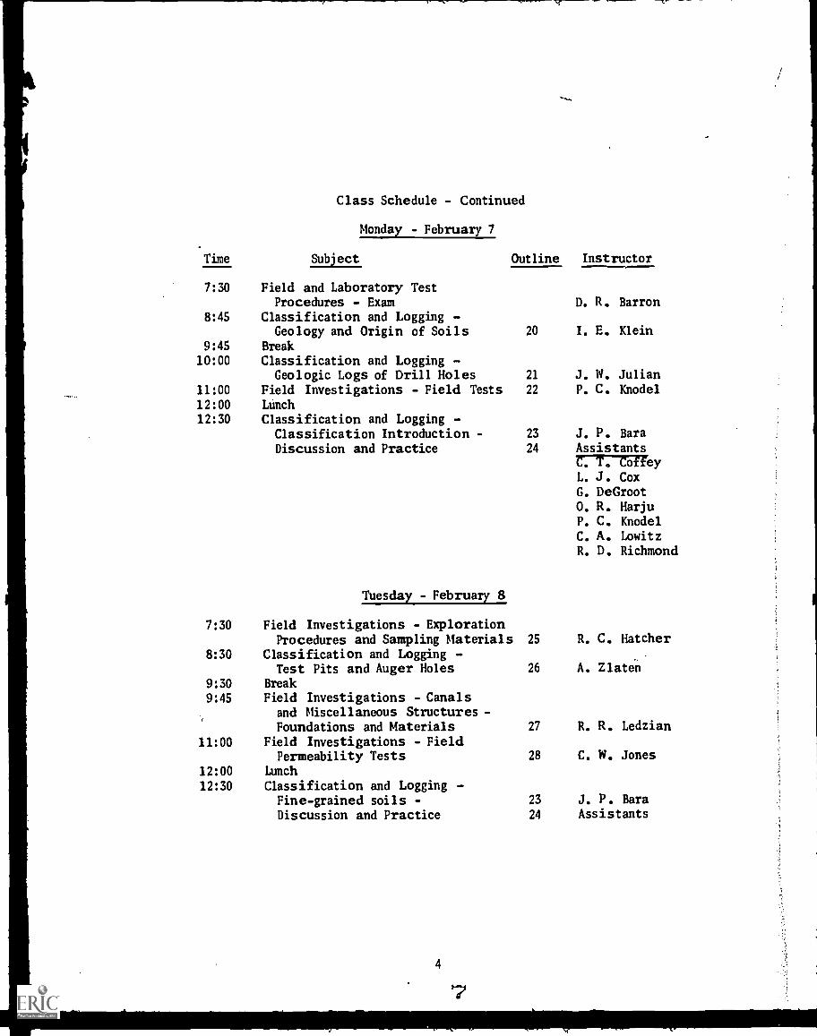
Time
Class Schedule - Continued
Monday - February 7
Sub'ect
7:30 Field and Laboratory TestProcedures - Exam
8:45 Classification and Logging -
Outline Instructor
D. R. Barron
Geology and Origin of Soils 20 I. E. Klein
9:45 Break
10:00 Classification and Logging -Geologic Logs of Drill Holes 21 J. W. Julian
11:00 Field Investigations - Field Tests 22 P. C. Knodel
12:00 Lunch
12:30 Classification and Logging -Classification Introduction - 23 J. P. Bara
Discussion and Practice 24 AssistantsC. T. CoffeyL. J. CoxG. De Groot
0. R. HarjuP. C. KnodelC. A. LowitzR. D. Richmond
Tuesday - February 8
7:30 Field Investigations - ExplorationProc edures and Sampling Materials 25 R. C. Hatcher
8:30 Classification and Logging -Test Pits and Auger Holes 26 A. Zlaten
9:30 Break
9:45 Field Investigations - Canalsand Miscellaneous Structures -Foundations and Materials 27 R. R. Ledzian
11:00 Field Investigations - FieldPermeability Tests 28 C. W. Jones
12:00 Lunch
12:30 Classification and Logging -Fine-grained soils - 23 J. P. BaraDiscussion and Practice 24 Assistants
4
9
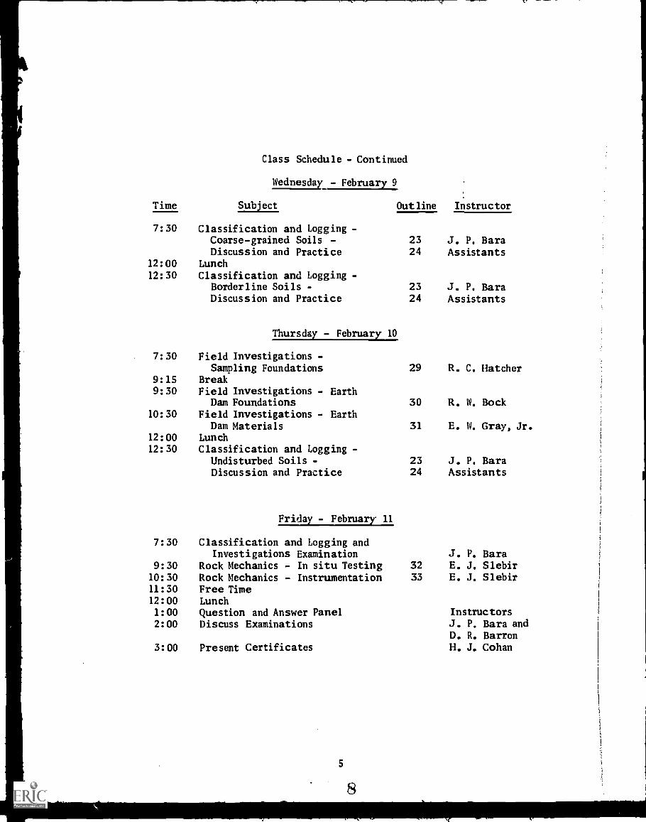
Class Schedule - Continued
Wednesday - February 9
Time Sub'ect Out line Instructor
7: 30 Classification and Logging -Coarse-grained Soils - 23 J. P. BaraDiscussion and Practice 24 Assistants
12: 00 Lunch12:30 Classification and Logging -
Borderline Soils - 23 J. P. BaraDiscussion and Practice 24 Assistants
Thursday - February 10
7:30 Field Investigations -Sampling Foundations 29 R. C. Hatcher
9:15 Break9: 30 Field Investigations - Earth
Dam Foundations 30 R. W. Bock10: 30 Field Investigations - Earth
Dam Materials 31 E. W. Gray, Jr.12:00 Lunch12:30 Classification and Logging -
Undisturbed Soils - 23 J. P. BaraDiscussion and Practice 24 Assistants
Friday - February 11
7: 30 Classification and Logging andInvestigations Examination J. P. Bara
9:30 Rock Mechanics - In situ Testing 32 E. J. Slebir10:30 Rock Mechanics - Instrumentation 33 E. J. Slebir11:30 Free Time12: 00 Lunch1:00 Question and Answer Panel Instructors2:00 Discuss Examinations J. P. Bara and
D. R. Barron3: 00 Present Certificates H. J. Cohan
5

Aikele, John H.
Bara, John P.
Barron, Donald R.
Bock, Richard W.
Callow, B. A.
Coffey, Carroll T.
Cotton, Charles E.
Cox, Lyman J.
Daehn, Wilmar W.
Davis, Fred J.
De Groot, Glenn
Ellis, Willard
Gebhart, Lloyd R.
Gibbs, Harold J.Gray, Edward W.
Groseclose, William R.
Hatcher, Robert C.
Harju, Oiva R
Howard, Amster K.
Jones, Chester W.
INSTRUCTORS
Engineering TechnicianEarth Sciences Branch
Civil EngineerEarth Sciences Branch
Civil EngineerEarth Sciences Branch
Civil EngineerEarth Dams Section,Hydraulic Structures Branch
Engineering TechnicianEarth Sciences Branch
Engineering TechnicianEarth Sciences Branch
Engineering TechnicianEarth Sciences Branch
Engineering TechnicianEarth Sciences Branch
Civil EngineerStructural Behavior andAnalysis Section,Hydraulic Structures Branch
Civil EngineerEarth Dams Section,Hydraulic Structures Branch
Civil EngineerEarth Sciences Branch
Section Head
Soil Properties TestingSection, Earth Sciences Branch
Civil EngineerConstruction Liaison
Chief, Earth Sciences BranchCivil Engineer
Earth Dams Section,Hydraulic Structures Branch
Civil EngineerConstruction Liaison
Engineering TechnicianEarth Sciences Branch
Civil EngineerEarth Sciences Branch
Civil EngineerEarth Sciences Branch
Section Head
Special Investigations andResearch Section, EarthSciences Branch
6
9

Julian, J. Willard
Kingery, Richard I.
Klein, Ira E.
Knodel, Paul L.
Kramer, Richard W.
Ledzian, Robert R.
Lowitz, Clemith A.
McAlexander, Errol L.
Merriman, John
Richmond, Robert D.
Roselle, Larry A.
Slebir, Edward J.
Talbott, George H.Tiedemann, Drew A.
Zlaten, Alexander
B. P. BellportH. J. Cohan
R. A. GullettJ. W. HilfH. S. LathamW. W. Reedy
INSTRUCTORS - Continued
GeologistGeology and GeotechnologyBranch
Engineering TechnicianEarth Sciences Branch
GeologistGeology and GeotechnologyBranch
Civil EngineerEarth Sciences Branch
Civil EngineerStructural Behavior andAnalysis Section, HydraulicStructures Branch
Civil EngineerEarth Sciences Branch
Civil EngineerEarth Sciences Branch
Civil EngineerEarth Dams Section,Hydraulic Structures Branch
Civil EngineerEarth Sciences Branch
Civil EngineerEarth Sciences Branch
Engineering TechnicianEarth Sciences Branch
Civil EngineerEarth Sciences Branch
Chief, Field Coordination BranchCivil Engineer
Earth Sciences BranchCivil Engineer
Earth Dams Section,Hydraulic Structures Branch.
SPEAKERS
Director, Design and ConstructionActing Chief, Division of General
ResearchChief, DivisionChief, DivisionChief, DivisionChief, Division
Coordination
7
10
of Constructionof Designof Safetyof Planning

1972EARTH CONTROL AND INVESTIGATIONS TRAINING COURSE
PARTIC I PANTS
Name
Floyd A. AshbaughLeo R. MollotteJames A. Waters
Richard B. Burket
Kenneth H. EddyJoseph PerryGayland SnowJack L. TylerRobert Barbo
Wayne E. AndersonCharles L. Howard
Howard W. GraesingBoyd M. RichardsonDavid M. Sparks
Earl E. Burnett
George D. EwoldtGilbert D. FordCharles W. Winzer
Ronald M. Merkley
Dan N. Page
Robert J. AtkinsFredrick N. Bailey
Pro'ect
REGION 1
Columbia BasinColumbia BasinColumbia Basin
Tualatin
Third PowerplantThird PowerplantThird PowerplantThird PowerplantSalem P 1 anning
Office
REGION 2
Regional OfficeRegional Office
Auburn-Folsom SouthAuburn-Folsom SouthAuburn-Folsom South
REGION 3
Yuma Projects Office
Central ArizonaCentral ArizonaCentral Arizona
Salt River ValleyWater UsersAssociation
Regional Office
REGION 4
Central UtahCentral Utah
8
Location
Ephrata, WashingtonEphrata, WashingtonEphrata, Washington
Forest Grove, Oregon
Grand Coulee; WashingtonGrand Coulee, WashingtonGrand Coulee, WashingtonGrand Coulee, WashingtonSalem, Oregon
Sacramento, CaliforniaSacramento, California
Auburn, CaliforniaAuburn , Cali forni a
Auburn, California
Yuma, Arizona
Phoenix, ArizonaPhoenix, ArizonaPhoenix, Arizona
Phoenix, Arizona
Boulder City, Nevada
Provo, UtahProvo, Utah

PaUl C. HancePaul E. HayesGeorge W. Hunt
G. Robert Murdoch
0. Herbert Spencer, :if,
Ray J. Buckley
Jack E. Hockemeier
Eugene L. Rodriguez
Carrol J. Newcomb
IJames E. Drake
Larry W. Ellenberger
Leslie G. Fowler, Jr.
Carrol W. Mustion
John W. Sissel
Gary A. Jones
Tony J. CappellucciEllsworth H. Fletcher
Louis V. GeorgeClyde H. GleasonLymen B. McCall
REGION 4 - Continued
Central UtahCentral UtahCentral Utah
Regional Office
Curecanti Unit, CRSP
REGION 5
Mountain Park
Navajo IndianIrrigation
Navajo IndianIrrigation
Provo, UtahProvo, UtahProvo', Utah
Salt Lake City, Utah
Montrose, Colorado
Altus, Oklahoma
Farmington, New Mexico
Farmington, New Mexico
Oklahoma City Oklahoma City, OklahomaDevelopment Office
REGION 6
Garrison DiversionUnit
Garrison DiversionUnit
Garrison DiversionUnit
Garrison DiversionUnit
Garrison DiversionUnit
Missouri-OaheProjects Office
REGION 7
Regional OfficeRegional Office
Fryingpan-ArkansasFryingpan-ArkansasFryingpan-Arkansas
9
12
Bismarck, North Dakota
Bismarck, North Dakota
Bismarck, North Dakota
Bismarck, North Dakota
Bismarck, North Dakota
Huron, South Dakota
Denver, ColoradoDenver, Colorado
Pueblo, ColoradoPueblo, ColoradoPueblo, Colorado

Kenneth R. PeddeBryan L. QueenRobert L. ReinhardtEmrys F. Samuelson
Toby J. KrugFrank J. Harela
Edward F. Monk
REGION 7 - Continued
Fryingpan-ArkansasFryingpan-ArkansasFryingpan-ArkansasFryingpan-Arkansas
North Platte RiverNorth Platte River
Pueblo, ColoradoPueblo, ColoradoPueblo, ColoradoPueblo, Colorado
Casper, WyomingCasper, Wyoming
ENGINEERING AND RESEARCH CENTER
Dennis H. McDonoughDavid W. Route
Alonzo J. Rue, Jr.David G. Miedema
Owen D. Mort
Ronald W. Weddell
John L. Hood
Frederick W.
Schulenberg
Clayton D. Richman
Kenneth L. Tompkins
Thamas A. Milbradt
Lynn Atkins
Edmundo Chame FilhoJabid Ahnad Shamiri
WASHINGTON OFFICE
Foreign Activities
OUTSIDE AGENCIES
Branch
Applied Sciences
Geology and GeotechnologyGeology and Geotechnology
Struct. and ArchitecturalStruct. and Architectural
Afghanistan - ProjectNo. 4
Texas Water Austin, TexasDevelopment Board
Bonneville PowerAdministration
Bonneville PowerAdministration
Forest ServiceForest Service
Soil ConservationService
Bureau of Mines
FOREIGN TRAINEES
10
13
Portland, Oregon
Portland, Oregon
Denver, ColoradoDenver, Colorado
Denver, Colorado
Spokane, Washington
Brazil
India

Outline No. 1
CONSTRUCTION CONTROL INTRODUCTION
A. Introduction
B. Types of Laboratories
1. Type C - Large
2. Type B - Medium
3. Type A - Small
(1) Stationary
(2) Mobile
4. Vehicle
S. Combinations of types of laboratories
C. Laboratory Equipment
1. Calibration
2. Care and maintenance
3. Use
Study references: Earth Manual
Laboratories pages 187-190Laboratory equipment pages 400-408
Outline No. 2
FUNDAMENTAL DEFINITIONS
A. Introduction
1. Purpose
2. Test procedures to be covered
a. Field density
b. Lab compaction
c. Standard properties
d. Permeability and settlement
e. Rapid compaction control
B. Field Density
1. Designation E-24, page 582
2. Density calculations
C. Laboratory Compaction
1. Proctor compaction (cohesive soils), Designation E-11,page 455
a. Density calculations
b. Penetration needle calculations
2. Relative density (cohesionless soils), Designation E-12,page 467
a. Miminum density calculations
b. Maximum density calcu'ations
c. Relative density calculations
12
15

D. Standard Properties
I. Samplepreparations, Designation E-5, page 408
2. Gradation analysis, Designation E-6, page 414a. Sieve analysis
calculationsb. Hydrometer analysis
calculations3. Soil consistency tests,
Designation E-7, page 426a. Liquid limit
b.Plastic limit
c. Shrinkage limit
d. Moisture content calculations4. Specific gravity, Designation E-10, page 442
a. Apparent specific gravitycalculations
b. Bulk specific gravitycalculations
E.Permeability and Settlement
1. Soils passing No. 4 sieve, Designation E-13, page 474j2. Soils containing gravel, Designation E-14, page 48913.
Coefficient ofpermeability and settlement
calculationsF. Rapid Compaction Control
1.Designation E-25, page 591
2.Calculations
G. Summary

Outline No. 3
FIELD AND LABORATORY TEST PROCEDURESFIELD DENSITY TEST
(Designation E-24, Earth Manual)
I. Introduction
A. Replacement methods
B. Definition
C. Uses of test
1. Construction control
2. Investigation work
D. Equipment
1. General equipment
2. Specific equipment - demonstration
3. Discussion of errors (replacement methods)
II. Test Procedure (USBR Method)
A. Preparation for test
1. Equipment
2. Control of minus No. 4 (fine-grained soils containinglittle or no gravel)
3. Control of ?Anus 3-inch soils (containing appreciablegravel)
4. Calibration procedure - demonstration
B. Field procedure
1. Selection of test site
2. Preparation of area
3. Placement of template
4. Excavation of test hole
S. Measurement of volume of hole
14
1

C. Laboratory procedure - cohesive soils (see Earth Manual,page 586, or Drawing No. 101-D-285)
D. Laboratory procedure - cohesionless soils
III. Demonstration of Special Equipment
A. Speedy moisture meter
B. Nuclear moisture - density equipment
IV. Practical Exercise
A. Discussion of data sheets
1. 7-1425 Field Density Record
2. 7-1657 Calibration of Sand Density Test Apparatus andDensity Sand
B. Calibration of density sand - class
C. Sample calculations - field density tests
V. Summary
Study references: The following references are found in the EarthManual, Revised Edition, 1968.
1. Designation E-24, Field Density Test Pro-cedure, pages 582-591
2. Chapter III, Control of Construction,pages 248-251, page 300
3, Practice Problem Handouts
15
1.8

FIELD AND LABORATORY TEST PROCEDURESCOMPACTION, RELATIVE DENSITY
A. Introduction - Compaction
1. Origin
2. Summary of compaction standards
a. ASTM
b. AASHO - Standard
c. AASHO - Modified
d. Corps of Engineers - Modified (airfields)
e. USBR - Large scale
f. USBR - Standard
3. Specifications of equipment
a. Equipment (calibration)
(1) Hand equipment
(2) Mechanical compactors
b. Soil
4. Test procedure
a. Mechanics of the test
b. Moisture determination
(1) 16 hours at 110° C±
(2) Size sample .
c. Computation and plotting
d. Source of error
16
19
Outline No. 4
.3

S. Penetration resistance
a. Use of the penetrometer
b. Source of error
c. Value of the penetration resistance curve
6. Zero air voids curve
a. Significance of the curve
b. Computations - Zero air voids curve
7. Materials adaptable to compaction
a. Processing
b. Types of curves to expect
8. Value of the compaction test
B. Introduction - Relative Density
1. Origin
2. Specifications
a. Equipment
b. Materials
3. Test procedure
a. Minimum density
b. Maximum density
4. Calculations and use of nomograph
S. Value of relative density test
Study references: Earth Manual, Designation E-11, ProctorCompaction Test, pages 455-467; EarthManual, Designation E-12, Relative Densityof Cohesionless Soils, pages 467-474
17
20

Outline No. 5
LABORATORY TEST PROCEDURESSAMPLE PREPARATION, GRADATION,
ATTERBERG LIMITS, SPECIFIC GRAVITY'
I. Presentation
A. Introduction
B. Sample preparation
1. Visual inspection and classification
2. Synthetic gradation analysis
3. Preparation of composite samples
C. Gradation test
1. Purpose and definition of terms
2. Separation of No. 4 sieve
3. Hydrometer analysis (ninus No. 4 material)
4. Mechanical analysis
5. Computation and plotting
6. Interpretation of test results
D. Atterberg limits test
1. Purpose and definition of terms
2. Sample preparation
3. Liquid limit
a. One-point method
4. Plastic limit
5. Plasticity index
6. Shrinkage limit
7. Interpretation of test results
E. Specific gravity test
1. Purpose and definition of terms
2. Sample preparation
3. Test procedure for minus No. 4 material
4. Test procedure for plus No. 4 material
II. Review
A. Answer student questions
B. Summarize main topics
Study references: Earth Manual, Designation E-5, Preparationof Soil Samples for Testing, pages 408-414;Designation E-6, Gradation Analysis of Soils,pages 414-426; Designation E-7, Soil Consist-ency Tests, pages 426-437; Designation E-10,Specific Gravity of Soils, Aggregate,pages 442-453

Outline No. 6
FIELD AND LABORATORY TEST PROCEDURESPERMEABILITY AND SETTLEMENT OF SOILS
I. Introduction
A. Types of permeability tests
B. Purpose of test
1. Determination of coefficient of permeability
2. Determination of percent consolidation
C. Principle
1. Darcy's Law
2. Ranges of permeability
3. Standard overburden loads
II. Test Procedure - Standard Test
A. Apparatus
1. Equipment
2. Calibration of constant-head tank
B. Preparation of sample
1. Data needed before test
2. Moisture
C. Placing of specimen
1. Check preparation sheet and compute data for packing
2. Check equipment
3. Ring readings
4. Placing specimen
5. No-load readings
6. Loading
20 096., CP

D. Application of water to sample
1. Procedure
2. Readings
E. Sample removal
1. Final readings (loaded)
2. Rebound
3. Penetration resistance needle test
4. Moisture
III. Test Results
A. Calculations
1. Coefficient of permeability
2. Settlement due to saturation
B. Sources of error
1. Piping
2. Entrapped air and foreign matter
3. Temperature
4. Permeability of apparatus
S. Ihalidity of Darcy's Law
C. Reporting results in L-29 report
IV. Other Laboratory Permeability Tests
A. Undisturbed samples
B. Nonloaded soil specimens
C. Soils containing gravel
21

Study references: All of the references below are contained inthe Earth Manual:
Chapter I, Section 21, pages 60-65, Per-meability; Chapter III, Section 62,pages 218-220, Permeability; DesignationE-13, pages 474-489, Permeability andSettlement of Soils; Designation E-14,pages 489-492, Permeability and Settlementof Soils Containing Gravel
22
25

Outline No. 7
FIELD AND LABORATORY TEST PROCEDURESRAPID COMPACTION CONTROL
A. Introduction
1. Provides a means of construction control for fine-grainedsoils which is accurate and can normally be performed in1 to 2 hours.
a. Density control - degree of compaction (percent ofmaximum dry density) is precisely determined.
b. Moisture control - difference from optimum is deter-mined to a satisfactory degree of accuracy.
2. Density and moisture conditions must be campared to stand-ards to confirm that the field conditions are similar tothose assumed during design.
B. Theory
1. Dry density determination based on oven poisture determi-nation which requires 16 to 24 hours.
2. Rapid method control based on relating all densities tothe wet density at fill water content.
3. Red line corrections for moisture control based on mois-ture and density characteristics of average soils. Thesecorrections are necessary since water contents added arebased on wet weights rather than dry weights.
C. Practice Problems
1. Symbols
Fill wet density (pcf) ywf
Cylinder wet density (pcf) ywc
Maximum density point of converted wet density curve(pcf) ym
Fill water content 00 wf
Optimum water content (%) wo
Z6
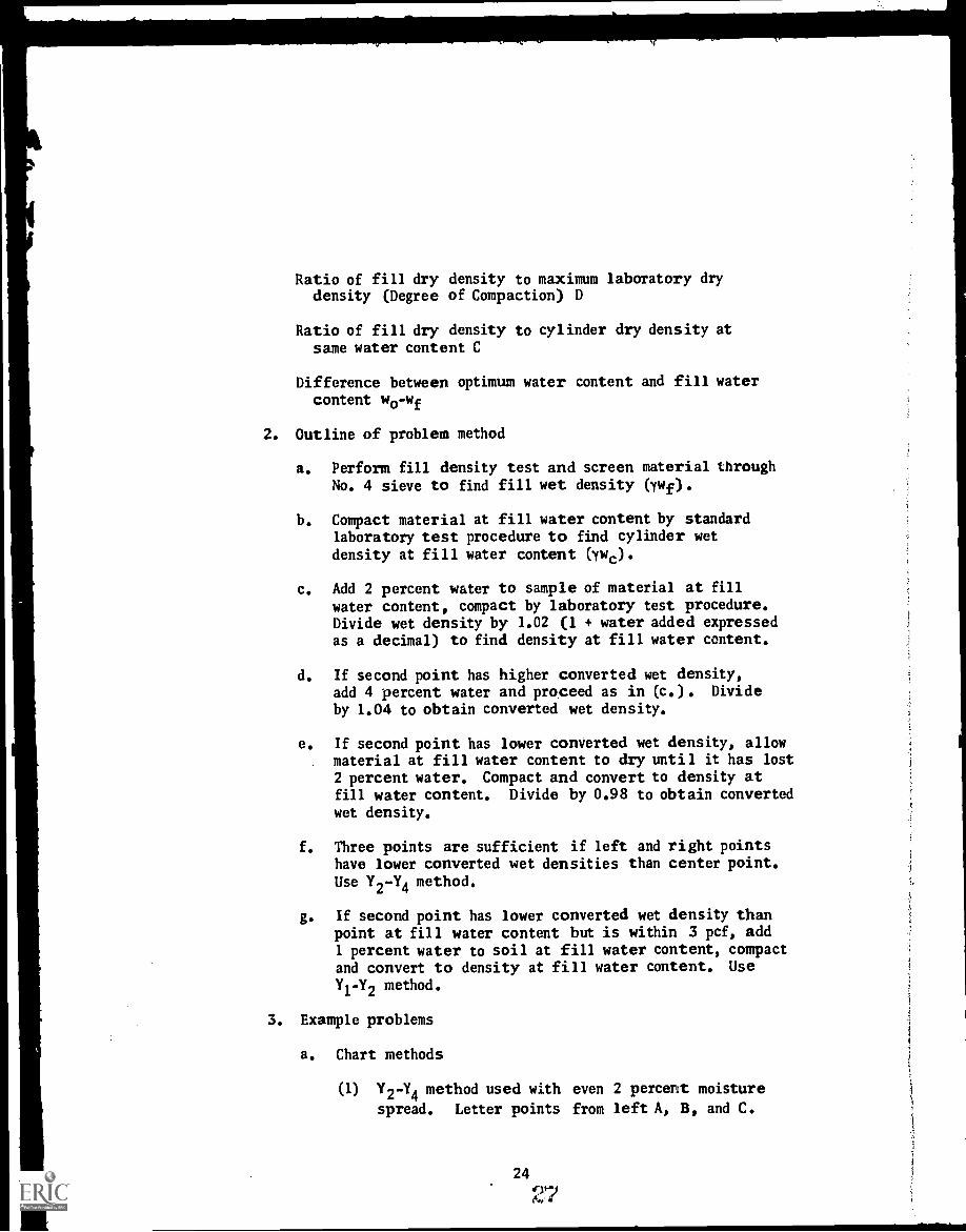
Ratio of fill dry density to maximum laboratory drydensity (Degree of Compaction) D
Ratio of fill dry density to cylinder dry density atsame water content C
Difference between optimum water content and fill watercontent wo-wf
2. Outline of problem method
a. Perform fill density test and screen material throughNo. 4 sieve to find fill wet density (rwf).
b. Compact material at fill water content by standardlaboratory test procedure to find cylinder wet
density at fill water content (ywc).
c. Add 2 percent water to smnple of material at fillwater content, compact by laboratory test procedure.Divide wet density by 1.02 (1 + water added expressedas a decimal) to find density at fill water content.
d. If second point has higher converted wet density,add 4 percent water and proceed as in (c.). Divideby 1.04 to obtain converted wet density.
e. If second point has lower converted wet density, allow. material at fill water content to dry until it has lost
2 percent water. Compact and convert to density atfill water content. Divide by 0.98 to obtain convertedwet density.
f. Three points are sufficient if left and right pointshave lower converted wet densities than center point.Use Y
2-Y
4method.
g. If second point has lower comerted wet density thanpoint at fill water content but is within 3 pcf, add1 percent water to soil at fill water omrtent, compactand convert to density at fill water =tent. UseYi-Y2 method.
3. Example problems
a. Chart methods
(1) Y2-Y4 method used with even 2 percent moisture
spread. Letter points from left A, B, and C.
24
{44

Values in chart give ordinates of the maximumdensity point of the converted wet density curvefrom Point A.
(2) Y1-Y
2method used with even 1 percent moisture
spread (eliminates need for drying back if con-verted wet density of point with 2percent addedwater is lower in density but within 3 pcf ofpoint at fill water content).
(a) Number points in order in which they wererun (i.e., Point (1) at fill water content,Point (2) with 2 percent water added,Point (3) with 1 percent water added).
(b) Values in chart give ordinates of the max-imtnn density point of the converted wetdensity curve from Point (1).
(c) If the ratio of Y1/Y2 is greater than 0.38
or if the Zm obtained from the chart is lessthan -1.0, this method is not consideredapplicable. In that case, a dry batk pointshould be obtained and the problem solvedby Y2-Y4 method.
b. Graphical methods - outlined on cover sheet
(1) Can be used on all problems but is more time-consuming than chart methods.
(2) Must be used if uneven moisture spread is obtained.
c. Both chart and graphical parabola methods assume thatthe compaction curve can be approximated by a parabolawhose axis is veatical.

4. Calculations
a. Rapid control method
Fill wet density (ywf)
C Cylinder wet density of materialat fill water content (ywc)
DMaximum density point of converted
wet density curve (ym)
Fill wet density (ywf)
wo-wf = Added water at Point A + xm + red line correction
b. For record purposes after fill water content has beendetermined wf = fill water content expressed as a
decimal (e.g., 10% = .10)
Fill dry density = Fill wet density (ywf/(1+wf)
Maximum density point of convertedwet density curve (ym)
(l+wf)Lab max dry density
Cylinder dry density -
Cylinder wet density of materialat fill water content (ywc)
(l+wf)
Optimum water content = Wf + (l+wf)(added water atmaximum density point)
5. Class exercise
a. Test apparatus
b. Rapid compaction test
c. Computations and discussion
Study references: Earth Manual, Designation E-25, pages 591-613Engineering Monograph No. 26Practice Problems Handout
26

Outline No. 8
CONSTRUCTION CONTROL - EARTH DAMS
A. Introduction
1. Importance of construction control
2. Control related to investigation and design
3. Comparison of soils with other construction materials
4. History of earthwork control
5. The modern concept
B. Foundations
1. Types
2. Control of treatment
3. Dewatering
C. Impervious Zones (Rolled Earthfill)
1. Criteria of satisfactory impervious zones
2. Control features of each criterion
3. Moisture and density control
4. Types and frequency of tests
D. Compacted Pervious Zones
1. Criteria of satisfactory pervious zones
2. Control features of each criterion
3. Moisture and density control
4. Types and frequency of tests
27

E. Riprap and Rockfill
I. Criteria of satisfactory riprap and rockfill
2. Control features of each criterion
F. Summary
Study reference: Earth Manual, Chapter III, Parts A, B, C, D
4
i
28
CONSTRUCTION CONTROL - Eivrni DAMS
QUALITY CONTROL
A. Reporting Tests
1. Forms
2. Reports
B. Analysis of Field Control Tests
1. Design recommendations
2. Summary of quality control.
29
22
Outline No. 9

Outline No. 10
EARTH DAM INSTRUMENTATION
A. Types of Instruments and their Purpose
1. Pressure measurement apparatus - pore water pressure
a. Dams
b. Structures
2. Internal movement apparatus
a. Vertical movement devices
b. Horizontal movement devices
c. Foundation settlement, baseplate devices
3. Surface measurement points
a. Embankments
b. Structures
c. Land movements
4. Seismic apparatus
a. Accelerographs
b. Seismic - seismographs
B. Description of Apparatus
1. Twin-tube piezometers
2. Porous-tube piezometers
3. Internal movememt apparatus
a. Vertical movement (crossarm) devices
b. Horizontal movement devices
4. Foundation settlement (baseplate) devices
-;

5. Measurement points
a. Embankments
b. Structures
6. Seismic
a. Accelerographs and seismographs
C. Materials for Instrument Installatians
1. Purchase by Government for Government installation
2. Purchase by Government for contractor's installation
3. Purchase and installation by contractor
D. Installation of equipment by
1. Government forces
2. Contract specifications
a. Prime contract
b. Special contract or extra work order
c. Supplemental contract
E. Reports Required on Installations
1. During construction - progress report - monthly - L-15
2. At completion of construction L-16
3. At scheduled intervals - periodic L-23
F. Quality of Data Obtained
1. Care during installation
2. Maintenance of recording apparatus
3. Possible failure of equipment
31
o)Aeji.k

G. Forms Used for Reporting Data on Instrument Installations
1. 7-1346, 7-1347, 7-1348, 7-1355, 7-1355A, 7-1359, 7-1600,and special forms
H. Suggestions for Improving Apparatus
1. Field reports on malfunction of equipment
2. Field suggestions for design changes
3. Awards
Study references: Earth Manual, pages 258-264, Designations E-27to E-35

Outline No. 11
EARTH DAM INSTRUMENTS - APPLICATION OF DATA
I. Why Instrumentation?
A. Verify design assumptions
B. Monitor structure for potentially dangerous conditions
II. Instruments and Information
A. Movements
1. Internal vertical movement (crossarm) device
2. Internal horizontal movement device
3. Surface measurement points
4. Deflectometer
S. Foundation settlement baseplate
B. Pressures
1. Twin-tube piezometers
2. Porous-tube piezometer
3. Standpipe
C. Seepage
1. Flow-measurement devices
2. Reservoir level gage
3. Pressure measurement devices in B
D. Earthquake effects
III. Examples of Applications
IV. Data Collection (more than filling out forms)
V. Summary
33

SPECIAL LABORATORY TESTS
A. Introduction
Outline No. 12
The special tests of the laboratory are described to acquaintthe field personnel with the facilities of the laboratory andhow the materials sent from the field are studied.
B. Consolidation Test
1. Purpose and use in undisturbed soils and in disturbed soils
2. General discussion of the principle
a. Load - consolidation
b. Time - consolidation
3. Sample preparation and equipment operation
4. Results obtained
5. Permeability testing
6. Use for expansion determination
C. Shear Tests
1. Purpose and use in undisturbed soils and in disturbed soils
2. General discussion of the principle
3. Equipment available and types of tests
a. Equipment: small, medium, and large
b. Special features of the equipment
c. Unconfined compression test
d. Adaptations of standard shear tests with comments onthe purpose

D. Earthquake Test
1. Purpose of test and applications
2. Equipment and operation
3. Evaluation of results
Study references: Earth Manual, Designation E-15

Outline No. 13
CONSTRUCTION CONTROL - CANALSAND MISCELLANEOUS STRUCTURES
Note: All references are to pages in the Earth Manual.
A. Introduction - Ref. Part C, pages 212-228 and Parts E and F,pages 274-325.
Purpose of this lecture is to discuss basic techniques andfundamentals for examining and controlling quality in founda-tions and miscellaneous earth structures.
B. Basic soil types and problems concerning foundations (Refer-ence: "Engineering Use Chart," Figure 8, page 23).
1. Clays - (1) firm consolidated, (2) compressible,(3) expansive
2. Silts and low plasticity clays - (1) low density and(2) dense
3. Sands and coarse-grained soils - (1) denseness and(2) permeability
4. Rock and formation material
C. Inspection of Foundations
1. Methods of inspection and engineering guidelines
2. Protection against disturbance
3. Awareness of foundation discontinuities
4. Effect of saturation - (1) collapse, (2) expansion,(3) strength loss
5. Seepage and piping
6. Piles and caisson foundations
D. Considerations for Canal Subsoils
1. Seepage
2. Erosion
3. Ground water
36

E. Consideration for Pipeline Subgrades
F. Control Criteria of Special Interest
1. Expansive clay - Reference: pages 226-227Discussion of Table 3, page 227
2. Collapsing soil - Reference: pages 222-226
a. Discussion of Figure 82, page 225
b. New chart of density versus liquid limit
3. Other uses of the density versus liquid limit chart
a. Trends of recompacted soil
b. Soft saturated and sensitive soils
c. Experience with expansive soil - New ideas ofcontrolling by moisture content
4. Criterion for selecting well-graded backfill(References: Figure 103, page 293).
a. Variations of fines
b. Variations described in ASTM: D 1241 and our usefor surfacings and subbase.
5. Recommended relative densitiy limiting requirements forgranular material (Reference: page 313).
6. Discussion of pile-driving formulas and estimating lengthfrom penetration resistance test (Reference: pages 316-318).
7. Comment of frost action limitations (Reference: page 69).
8. Guideline for use of relative density control versusProctor compaction. Also these guidelines are related tovibratory compaction as opposed to roller compaction(Reference: page 321 and Table S, pages 287-291).
9. Latest criteria for canal cioss section (Reference: Fig-ure 100, pages 280-281).
10. New chart for recanmendations of desirable earth canallining material.
37

TYPES OF INFORMATION
USEFUL FOR VARIOUS SOILS
Sands & Gravels
Penetration Resistance
Gradation
Deosity
Relative Density
Silts & Low Plasticity Clays Clays & High Plasticity Clays
Penetration Resistance Moisture Penetration Resistance to Show in
Important & Moisture Change Place Firmness
Must Be Considered
Dtusity + Moisture
Liquid limit
Gradation
Undisturbed Samples for Laboratory
Testing
Gradation with Colloid Content for
Expansion Question
Density + Moisture
Liquid Limit
Plasticity Index
Shrinkage Limit
38
Vane Test in Soft Saturated Soil
with Penetration<10 Blows
Undisturbed Samples for Laboratory
Testing

Outline No. 14
CONSTRUCTION CONTROL - FIELDLABORATORIES AND REPORTS
A. Introduction - Inspection (Ref. Art 49, page 185)Discuss intent of this lecture.
B. Field review of field laboratories and why they are made.Annual report of field laboratory survey.
1. Basic information furnished
2. Special instructions regarding forms
3. What is done with the report
C. Construction Control Reports (Ref. Art 51, page 190)
1. Purpose
2. Scope of reports (Ref. Reclamation Instruction, Part 175,"Records of Construction and Structural Behavior, Chapter 1,Periodic Reports," Paragraph 175.1, 12)
a. Narrative - What is wanted.
b. Summary of control data
(1) Form 7-1581A - Consolidated Earthwork (relativedensity)
(2) Form 7-1581B - Consolidated Earthwork (Proctorcompaction)
(3) Form 7-1737 - Compacted soil-cement
D. Type of Compaction Specifications
1. Method - Review Table 5, page 287
2. Performance
39

NPLJ
E. Whro. We Do With Control Reports
1. Initial review of L-29 reports
2. Monthly summary
3. Followup inquiries
4. Guidelines of testing frequency requirements and reworkedtests (refer to page 300)
40

Outline No. 15
CONSTRUCTION CONTROL - FILTERS
A. Pur ose of filters is to relieve seepage pressures in soiloundations and structures and carry off detrimental water.
B. Uses of filters are: (a) pervious blankets or drains undercanal linings, spillways, or dam aprons; (b) intercepting orsubsurface drains; (c) toe drains in earth dams or levees;and (d) weighted filters on critical areas subject to seepagepressures.
C. Component parts are base materials (foundation soils), one ormore pervious filter layers with or without open-jointed orperforated pipe.
D. General requirements are that voids in filter be sufficientlysmall to prevent penetration by base material but sufficientlylarge and interconnected to readily transmit seepage water.Pipe joints or perforations small enough to prevent infiltrationof filter material.
E. Filter criteria are based on results of laboratory filtrationtests on typical base and filter materials. USBR filter tests(including preliminary tests on crushed rock) described inreport in EM-425 (1955).
F. Selection of filter material is based primarily on grading ofTTIEFFEaerial in relation to grading of base material. Forthis purpose certain percent sizes are established for use incontrolling the grading of the filter material within limitson these sizes.
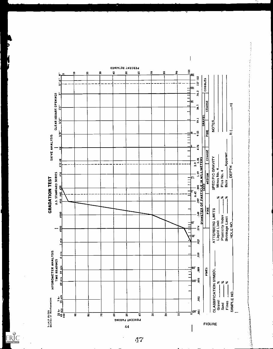
G. As an example of a given percent size the 50 percent size isshown on the standard gradation test sheet as the particlesize (abscissa), corresponding to the point where the gradingcurve intersects the 50 percent finer line of the ordinate.It is the size in a soil sample such that 50 percent by weightof the sample contains larger particles and 50 percent containssmaller particles.
41
44

H. USBR Filter Test Criteria
1. General
a. The maximum size of material should be 3 inches.
b. Not more than 5 percent should pass the No. 200 sieve.
c. For base materials containing more than 10 percent plusNo. 4 and more than 10 percent of minus No. 200 material,the filter grading should be selected on the basis of theminus No. 4 fraction of the base material.
d. The maximum size of pipe openings or perforations shouldbe one-half the 85-percent size of the adjacent filtermaterial.
2. Natural subrounded materials
For uniform grain size filter material
50% size of filter material50% size of base material
- 5 to 10
For graded filter materials
and
50% size of filter material12 to 58
50% size of base material
15% size of filter material12 to 40
15% size of base material
3. Crushed rock (tentative criteria)
and
50% size of filter material50% size of base material
9 to 30
15% size of filter material15% size of base material
= 6 to 18
42

I. Construction Recommendations
1. Base material should be lightly compacted and all holesfilled.
2. Segregation of filter material should be minimized bymoistening and careful placement procedures.
3. Filter materials should be compacted.
4. Infiltration of filter material into drainpipe duringfilter placement should be prevented.
Study reference: Earth Manual, pages 322-325
43
4-6
Mid
7-14
15 (
8-70
)B
urea
uof
Rec
lam
atio
n
5
1
HY
DR
OM
ET
ER
AN
ALY
SIS
GR
AD
AT
ION
TE
ST
SIE
VE
AN
ALY
SIS
25 IS 00 90 80 70 60 50 40 20 10
TIM
E R
EA
DIN
GS
hr7
hrm
in15
min
60 m
in19
min
4 m
inI m
M#2
00IN
I00
U.S
. ST
AN
DA
RD
SE
RIE
S
#50
#40
#30
#
IC
LEA
R S
QU
AR
E O
PE
NIN
GS
#10
#8#4
3/8"
3/4"
I W '
3"5"
6"
8" 10 20 30 40 so 60 70 80 90 10
I I
II 1 II I
El
III
11.1
1114
1111
111
I
0.42
2.0
.001
.002
.005
.009
.019
.037
.074
.149
FIN
ES
.297
.590
1. 9
2.38
D 1
AM
ET
ER
OF
PA
RT
ICLE
IN M
ILLI
ME
TE
RS
SA
ND
ME
DIU
MI
CO
AR
SE
IF
INE
4.76
FIN
E
9.52
19.1
38.1
76.2
127
152
GR
AV
EL
CO
AR
SE
CO
BB
LES
Do
CLA
SS
IFIC
AT
ION
SY
MB
OL
AT
TE
RB
ER
G L
IMIT
SS
PE
CIF
IC G
RA
VIT
Ym
Gra
vel
%Li
quid
Lim
it%
Min
us N
o 4
San
d%
Pla
stic
ity In
dex
%P
lus
No.
4F
ines
%S
hrin
kage
Lim
it%
Bul
kA
ppar
ent
SA
MP
LE N
O,
HO
LE N
OD
EP
TH
i
NO
TE
S
ft (
m)
0
SOIL-CEMENT SLOPE PROTECTION
Outline No. 16
A. Used as slope protection on earth dams as a substitute forrock riprap
1. Cost of slope protection can be less with soil-cement sincerock is scarce and costly in some areas.
2. Use of soil-cement should be investigated if rock is morethan 20 miles away.
3. Local soils can normally be utilized with the addition of8 to 14 percent cement by dry weight of soil.
B. Historical Background. - Soil-cement had been used extensivelyin highway work for years.
1. Bonny Test Section using two soils was constructed in 1951.
a. Mixed-in-place construction procedures were used.
b. Soil-cement was placed in horizontal layers in a stair-step fashion up the slope.
2. Seven major Bureau of Reclamation structures have been facedwith soil-cement since 1963 using a total of 656,000 cubic
yards of soil-cement.
3. In addition, the Portland Cement Association lists 40 struc-tures faced with soil-cement. Volumes of these facings rangefrom 1,000 to 250,000 cubic yards.
4. Bid prices range from $6 to $9 cubic yard.
C. Material and Cement Content Selection
1. Gradation. - Preferred gradation is fairly well graded.
a. Well-graded materials require less cement.
b. Durability of individual grains checked by less violentdispersion action.
c. Deposits which contain lenses of clay should be avoided.
45

2. Compaction. - Material should compact to dense mass.
a. Significant increase of density at increase of cementcontent may indicate use of cement to fill voids.
b. Compaction test is used as a basis for placing testspecimens.
3. Durability Tests. - Used to evaluate resistance of soil-cement to weathering - ASTM test procedures.
a. Specimens are placed similar to compaction tests,using 0.033-cubic-foot mold.
b. Specimens are used for 7 days at 100 percent humidityand 70° F (fog room curing).
c. Wet-dry tests are wetted for 5 hours and dried at160° F for 43 hours.
d. Freeze-thaw tests are frozen 24 hours, thawed in fogroom for 24 hours.
e. Specimens are brushed with wire brush after each cycleand a total of 12 cycles are performed. Total loss isexpressed as a percentage.
f. Design criteria. - 6 percent max loss for wet-dry testsand 8 percent for freeze-thaw tests.
4. Compressive Strength Tests. - Used mainly as an indirectmeasure of equality.
a. Specimens are placed in 2.83- by 5.67-inch molds, 3-, 7-,28-, and 90-day tests.
b. Specimens are cured in fog room with 4- to 24-hour soak-ing period in water before testing.
c. Ends are capped with sulfur and tested at a rate of20 psi/sec.
d. Design criteria. - 600 psi minimum for 7-day specimens,875 psi minimum for 28-day specimens.
46
49

5. Compaction, Water Content, and Time Delay Effects
a. Increase of density usually increases quality.
b. Highest quality is usually obtained from 2 percent dryto optimum water content.
c. Due to cement-water reaction, quality decreases withtime delays; delays of 1 to 2 hours are usually not toocritical.
D. Construction Procedures
1. Material must be excavated and stockpiled in such a fashionthat a consistent material is fed to the mixer.
2. Soil and cement must be proportioned correctly prior tomixing.
a. Reciprocating plate feeder has been the most successfuldevice for soil feed.
b. Surge hopper with vane feeder is used to proportion thecement.
c. Both devices must be calibrated at start of constructionand checked occasionally.
d. Soil and cement are mixed with pugmill mixer and suffi-cient water is added during the mixing to bring thesoil-cement to the desired water content.
3. Mixed soil-cement is transported to the placement area withtrucks.
a. Soil-cement is spread to a uniform loose lift with dozer-mounted spreader.
b. Thirty-minute time limit from mixer to spreader on fill.
c. Approach rampslayers.
d. Slope of up toworking width.
must be adequate to protect previous
8:1 on placement is permitted to increase
47
50
1

4. Material is compacted with a combination of sheepsfoot andpneumatic-tired rolling.
a. Lower portion of lift is compacted with sheepsfootroller. Roller weight is adjusted until it begins towalk out.
b. Upper portion of lift is compacted with pneumatic-tiredroller. Roller weight is adjusted until it does notcause significant lateral movement of the soil-cement.
c. Time limits between each operation are 30 minutes.
S. Curing is usually accomplished by sprinkling.
a. Use of excessive water may be detrimental.
b. Water should be applied in a fine fog-type spray.
c. Smooth compaction plane is removed by brooming andbrooming is usually repeated to clean lift for nextlayer.
E. Construction Control Procedures
1. Gradation, specific gravity, and Atterberg limits tests arerun on soil.
2. Soil and cement feed are calibrated by timing feedsseparately.
a. Soil feed is checked by timing truckload during produc-tion and using cement feed calibration to determine soilweight.
b. Cement feed is usually quite consistent in a welldesigned plant.
c. Moisture contents are determined by "quick" methodsduring calibration.
3. Sample of soil-cement is obtained prior to compaction.
a. Laboratory compaction is performed at about the sametime as compaction on the placement to account for timedependency of soil-cement.
48
51

b. Fill density test is performed as soon as possibleafter compaction near the spot from which soil wastaken.
c. Unconfined compression specimens placed to densityfound in fill density test.
d. One test for every 500 cubic yards placed.
4. Chemical cement content determinations can be made if soilsource is low in calcium.
5. Construction control data is reported on Form No. 7-1737.
F. Record Coring
1. One core hole for every 5,000 cubic yards.
a. Unconfined compression and durability tests performedon representative pieces.
b. Comparisons with data from design tests indicate whethermaterial meets design requirements.
c. Core holes usually filled with grouted anchor bar toprovide quick reference for future inspections.
G. Portland Cement Association film "Soil-Cement Slope Protectionfor Earth Dams."
49

Outline No. 17
PLASTIC SOIL-CEMENT PIPE BEDDING
I. Introduction
A. First used by Bureau of Reclamation on Canadian RiverProject.
B. Conclusions of research done by American Pipe andConstruction Company.
1. The soil-cement backfill should be used only if thesoil can give adequate support for the pipe and trenchbackfill.
2. The cradle trench and soil-cement backfill eliminatelarge quantities of excavation and recompaction.
3. The soil-cement backfill provides uniform transfer ofload to the soil foundation.
4. The most suitable soil types for soil-cement are sandsand silty sand.
S. The total water requirement is a function of the per-cent fines and grain-size distribution within thematerial being used.
6. Cement requirements should be based on strength anddurability requirements for the bedding.
7. Seven-day compressive strengths of SO-psi minimum cannormally be obtained with 2 to 3 sacks of cement foreach cubic yard of bedding material.
8. Cement and water should be premixed before adding tothe soil.
9. A noncohesive soil can be mixed satisfactorily in adrum-type mixer.
II. Comparison of Bedding Methods and Materials Used
A. Conventional Bedding
1. Trench excavated to bottom of pipe
SO
5 '3

-
2. Material placed around pipe to specified depth
a. Consolidated to 70 percent relative densityfor free-draining material
b. Compacted to 95 percent of Proctor maximumdry density for fine-grained material
3. This method often requires considerable labor.
B. Plastic Soil-cement Pipe Bedding
1. Trench excavated to depth corresponding to top ofbedding - springline elevation. (Depth of beddingdepends on design of pipe.)
2. Remainder of trench is excavated as semicircularsection 4 to 6 inches greater in diameter than theoutside diameter of the pipe.
3. Pipe sections are supported about 2 inches abovethe trench bottom on sand pads.
4. Annular space filled with plastic soil-cement.
5. This method eliminates the excavation and recompactionof the block of material between the springline andbottom of the pipe. It also is a fairly mechanizedprocedure.
6. Material and cement content selection
a. Unconfined strength must be high enough to trans-fer pipe load to foundation (50-psi minimumusually desired).
b. After placement and initial set, volume changeshould be fairly small.
c. After set, material should be durable throughmoisture changes.
d. Sandy materials with less than 10 percent finesare usually suitable with about 10 percent cementby weight.
e. Strengths over 500 psi are not desirable as beddingmight alter shape of pipe.
III. Field Test Section
A. Installation. - Four sections of pipe installed using. four different soils for bedding material. Each soil
had 2-1/2 sacks of cement per cubic yard.
1. Mortar sand - fairly well-graded material with8-1/2 percent cement by weight.
2. Blow sands - uniform fine sands with 10 percentcement by weight.
3. Blow sands - uniform fine sands with 10 percentcement by weight.
4. Lean clay - medium plasticity fine-grained materialwith 11-1/2 percent cement by weight.
B. Curing. - Pipe sections left in place 7 days.
C. Measurements and Observations of Exposed BeddingMaterials.
1. Changes of diameter after exposure were small.
2. Exposed bedding showed that good contact had beenobtained.
3. All materials seemed to perform well but lab testingshowed clay material was not durable.
IV. Construction Control
A. Gradation. - Percentage fines and organic material con-trolling factors.
1. Maximum of 10 percent fines usually specified.
B. Compressive Strength. - Adequate compressive strengthto insure firm support required.
1. Companion compressive strength specimens should beformed for each 400 feet of pipe or at least twiceper shift.
a. Bedding material should be placed withoutconsolidation.
b. Tested after 7 days curing
52
t71-Ca

f-
2. Some specimens should be subjected to wet-dry cyclesto determine whether they are durable.
C. Batching. - Batching by weight preferred to provide moreconsistent results.
1. Water-cement ratio maximum usually specified as 3.5.
a. Water-cement ratio must be low enough to form afluid which will maintain sand in suspension.
2. Fluidity of mix checked by timing flow from a specialfunnel.
a. Funnel has 6 inches top diameter, 4-1/2 incheshigh with 11/16-inch opening.
b. Flow time to empty funnel should be 5 to 8 secondsto insure that material can be pumped and willfill space completely.
V. Summary
A. Cost reduction possible due to amount of excavation andcompaction which is eliminated.
B. Should be used only if the in-place soils can give ade-quate support to the pipe.
53
Outline No. 18
FIELD INVESTIGATIONS - INTRODUCTION TOFOUNDATION REQUIREMENTS
Note: References are to pages in the Earth Manual.
A. Introduction
Discussion of soil mechanics in investigating foundations andthe effect of foundation characteristics on the design of thestructure.
B. Basic Soil Mechanics Criteria for Analyses
1. Settlement must be within allowable limits.
2. Foundations must be safe against shear failure.
3. Specialized hydraulic structures require limitations inpermeability.
C. Foundation Problems
1. Exploration requirements - Reference: Figure 40, page 114;Figure 42, page 117.
2. Bearing capacity - Reference: page 212.
3. Stability - Reference: pages 213-216.
4. Permeability - Reference: pages 218-220.
D. Examples of Foundations With Respect to Soil Types. (Reference:pages 221-228.)
1. Clays
a. Firm consolidated clays
b. Compressive clays
c. Expansive clays
54

2. Silts .and intermediate soils
a. Low-density deposits
b. Normal, intermediate soil characteristics
3. Sands and coarse-grained soils
a. Importance of density
b. Desirable effects of gravel
4. Solid rock foundation
E. Discussion of Criteria for Evaluating Penetration Resistance

Outline No. 19
FIELD INVESTIGATIONS - RELATION TO PROJECT PLANNING
A. Introduction
1. Necessity for project investigations
2. Stages of investigation: Regional or basin planning, recon-naissance, feasibility, preconstruction
B. Project Plan Formulation
1. Multiple-purpose development
a. Joint uses
b. Conflicting purposes
2. Multiobjective planning
3. Deriving the plan
a. Concepts of plans
b. Alternatives
c. Incremental analyses
d. Benefit-cost ratio evaluation
e. Reimbursement
f. Environment and ecological considerations
C. Earth Control Investigations
1. Dams
a. Site-type relationships
b. Foundations, materials, and seepage
c. Spillway and other structural features

2. Canals, pipelines, and drains
a. Excavation materials
b. Stability, hydraulics, seepage, and lining
3. Tunnels
a. Excavation materials and construction methods
b. Pressures, support, lining
4. Structures
a. Foundations
D. Surveying and Mapping
1. Control topography, strip topography, fly lines
2. Uses: Land classification, layout, location of drillholes, etc.
3. Use of modern USGS quad sheets
4. Force account versus contracts
E. Explorations
1. Exploration required for each level of investigations
2. Force account versus contracts
3. Methods of exploration
a. Surface inspection
b. Photo and remote sensor interpretation
c. Pits and trenches
d. Auger boring
e. Drilling
f. Geophysical methods - electric logging, resistivity,and seismic
57
d'
4. Access to private property
a. Permission to enter
b. Legal condemnation
c. Damages and remuneration
Study references: Earth Manual, Chapter I, Properties of Soils;Chapter II, Investigations
58

Outline No. 20
CLASSIFICATION AND LOGGINGGEOLOGY AND ORIGIN OF SOILS
A. Introductory Remarks
1. The broad range of geologic conditions covered by the termH earth materials" or "soil."
2. The geological services of the Bureau.
B. Weathering and Erosional Processes
C. Examples of Earth Materials and Geologic Environments Involvedin Bureau Projects: Slide talk based on several projects - com-pleted, under construction, or proposed - illustrating investi-gations and operations of borrows with various geologicbackgrounds.
D. Sources of geologic information useful for earth materialsexploration and testing.
E. Summary

Outline No. 21
CLASSIFICATION AND LOGGINGGEOLOGIC LOGS OF DRILL HOLES
A. Use of Geologic Data in Engineering Operations
B. Reporting of Data
1. Purpose
2. Logs, sections, narrative
3. Standard forms
4. Ground-water levels
5. Soil classification symbols
6. Depth of exploration holes
7. Method of accOmplishing exploration holes
8. Physical description of material
9. Name of material
10. Miscel laneous
Outline No. 22
FIELD INVESTIGATIONS - FIELD TESTS
A. Standard Field Penetration Test, Designation E-21, Earth Manual,page 574
1. Purpose of test
2. Test procedure and requirements
3. Results
4. Use of data
B. In-place Vane Shear Test, Designation E-20, Earth Manual, page 562
1. 1 to 4 above
C. Methods for Determining In-place Density and Moisture
1. Hand methods
a. Undisturbed block, Designation E-2, Earth Manual, page 346
b. Undisturbed cylinder, Designation E-2, Earth Manual,page 346
c. Field density method, Designation E-24, Earth Manual,page 582
d. Auger method, Designation E-23, Earth Manual, page 579
2. Mechanical methods, Designation E-2, Earth Manual
a. Thin-wall drive samplers
b. Double-tube samplers
c. Core samplers
3. Nuclear method
Study reference: Earth Manual, Designations E-2, 2 0, 21, 23, 24
61
64

CLASSIFICATION AND LOGGING SOILCLASSIFICATION - INTRODUCTION
A. Introduction
Outline No. 23
1. Unified system, differences from other standards
2. Importance to engineers
B. Soi 1 Components
1. Size
a. Gravel (G)
b. Sand (S)
c. Silt and clay (M and C)
d. Organic (0)
2. Gradation (W or P)
3. Particle shape
4. Moisture
C. Classification of Soils
1. Field
2. Laboratory
D. Engineering Characteristics of Soil Components
E. Soil Descriptions
F. Engineering Comparisons of Soil Groups
G. Summary
Study reference: Earth Manual, pages 1-23, Designation E-3
62

Outline No. 24
CLASSIFICATION AND LOGGING CLASSIFICATION -
DISCUSSION AND PRACTICE
A. Clean, Coarse-grained Soils (GW, GP, SW, SP)Study references: Earth Manual, pages 379-388, 396-397
B. Fine-grained Soils (ML, CL, OL, MH, CH, 01-1, PT)Study references: Earth Manual, pages 388-394, 398-400
C. Coarse-grained Soils with Fines (GM, GC, SM, SC)
D. Borderline Soils
1. Well or poorly graded (GW-GP)
2. Gravel-sand mixture (GW-SW)
3. Clean or dirty (GP-GM)
4. Coarse or fine grained (GM-ML)
S. Silt or clay (ML-CL)
Study references: Earth Manual, pages 16-18, 387, 393, 397, 400
E. Classification of Undistrubed Samples
Study references: Earth Manual, pages 385, 394, 395Unified Soil Classification System(Supplement to the Earth Manual)
63
C.Jfe:;

-V
Outline No. 25
FIELD INVESTIGATIONS - EXPLORATION PROCEDURES
A. Introduction
B. Exploration Methods
1. Accessible methods of exploration
a. Trenching
b. Cuts
c. Test pits
d. Accessible boring
e. Accessib le caissons
f. Tunnels and drifts
g. Blasting
2. Nonaccessible methods of exploration
a. Auger boring (hand and power)
b. Ho 1 low-stem auger
c. Enclosed flight auger
d. Dr lye-tube boring
e. Percussion (churn) drilling
f. Jetting
g. Wash boring
h. Rotary drilling
i. Continuous sampl ing
C. Other Indirect Methods (only mentioned)
Study reference: Earth Manual, Chapter II, pages 133-154

Outline No. 25 - Continued
FIELD INVESTIGATIONS - SAMPLING MATERIALS
A. Introduction - Purpose
B. Disturbed Samples - Types, shipping containers, moisture-contentdetermination and records
C. Sampling Procedure
1. Sampling from accessible holes
2. Sampling from nonaccessible holes
a. Holes smaller than 8 inches
b. Holes larger than 8 inches
3. Sampling stockpiles
D. Logging and Data
E. Sample Size Requirements
F. Shipping Instructions
Study reference: Earth Manual, Designation E-1
65

Outline No. 26
CLASSIFICATION AND LOGGING LOGS OFTEST PITS AND AUGER HOLES
A. Introduction
1. Definition
B. Purpose of Log
1. Structures
2. Borrow areas
C. The Log Form
1. Percentage by volume of oversize
2. Natural density and moisture
3. Importance of soil classification
4. Description of soils in logs
D. Summary
Study reference: Earth Manual, pages 158-170
66

Outline No. 27
FIELD INVESTIGATIONS - CANALS AND MISCELLANEOUSSTRUCTURES - FOUNDATIONS AND MATERIALS
A. Introduction - Importance of Investigations
B. Planning Investigations
1. Review tentative plans for structures.
2. Review potential soil problems - early recognition.
3. Review local conditions, features, and performance ofsimilar construction.
4. Review previous investigation reports.
S. Degree of exploration varies with stage of investigation.
a. Investigate most serious.problems first.
b. Use methods appropriate to furnishing the desiredinformation.
6. Maps - Topography, geology and soil conditions, hydrology.
C. Stages of Investigation
1. Reconnaissance - Descriptive
a. Properties based on visual classification
b. General appraisal and evaluation of subsurface
2. Feasibility - Qualitative
a. Limited exploration - properties determined by indextests.
3. Specifications - Quantitative and specific
a. Engineering properties determined for various soiltypes.
b. Sufficient exploration to establish conditions at allcritical points.
67

4. Characteristics of subsurface developed in progressivelygreater detail as work proceeds.
D. Soil Components, Properties, and Characteristics
1. Boulders and cobbles - stable, occurrence in situ improvesstability, angularity increases stability.
2. Gravel and sand - easy to compact, little affected by mois-ture, not subject to frost action. Well graded less per-vious and more stable than poorly graded.
3. Silt - unstable with increise of moisture, tendency tobecome quick. Relatively impervious, difficult to compact,highly susceptible to frost heave, easily erodible, subjectto piping.
4. Clay - cohesive strength increases wiih decrease in moisture.Low permeability, difficult to compact when wet, subject toexpansion and shrinkage.
5. Organic matter - undesirable.
E. Engineering Use Chart - Relative desirability of typical soilsfor engineering purposes.
1. Compacted earth canal lining - impervious, erosion resistant,stable. Relative desirability - GW-GC, GC, SW-SC, 5C, SC-CL,CL, GM.
2. Structure backfill - desirability dependent upon backfillrequirements.
a. Impervious backfill impervious gravelly soils, SW-SC,SC, CL, SC-CL, SM-SC, SC-ML, etc.
b. Pervious backfill -
GW, GP, SW, SP <5 percent finesGW-GM, GW-GC, GP-GH, GP-GC <8 percent finesSW-SC and SM, require special consideration, suitabilitydependent on gradation and plasticity.
68

F. Surface Exploration - Familiarity with geologic landforms, soilsassociated with them, and potential problems.
1. Glacial areas
a. Heterogeneous - any type of soil, in almost any form,and in any proportion.
b. Hydraulic structures - sutiable design precautionsrequired.
c. Light structures no difficulty.
d. Heavy structures differential settlement.
2. Loessial areas
a. Settlement upon wetting
b. Piping
c. Recompaction - reliable platform for footings
d. Vertical slopes
3. Sand-dune areas
a. Transmission towers - seeding or road oil.
b. Piles to depth unaffected by any shifting of dunes.
c. Runoff very low.
d. Canals lined.
G. Subsurface Exploration - Identify soils in foundation, theirextent (dimensions), and properties.
1. Point structures (small buildings, towers) - a single holewill often be sufficient.
2. Powerplants and pumping stations - special attention
a. Vibrations and sensitivity to settlement.
b. Detailed and thorough. Holes at plant corners, turbinelocations, heavy bearing walls. Supplemented withadditional borings.
69
3. Switchyards - settlement and uplift
4. Line structures (canals, laterals, drains, etc.)
a. Spacing of holes dependent on subsurface.
b. Canals - feasibility, 1-mile intervals- specifications, 2,000-foot intervals
c. Minimum - 10 feet below invert grade, greater depthsfor questionable soils.
5. Borrow areas for canals - required excav.,tion, adjacentborrow, distant borrow.
H. Exploration for Materials with Specific Properties
1. Usually not feasible to obtain material with idealcharacteristics.
2. Volume substituted for quality; special processing may bemore economical than longer hauls.
3. Impervious materials - blending of coarse material withimpervious soil; erosion resistant and impervious.
I. Structure performance is dependent on investigation and infor-mation which is performed and provided.
Study assignment: Earth Manual, Chapter II
70

Outline No, 28
FIELD PERMEABILITY TEST (WELL PERMEAMETER METHOD)
A. Purpose is to obtain the permeability characteristics of thesoil in place, particularly for the estimation of canalseepage.
B. The Well Permeameter Test consists of the measurement of therate of water outflow (under constant head) from an uncasedwell augered in the soil to be tested.
C. The Detailed Test Procedure is presented in Designation E-19(pages 546-62) of the Earth Manual.
D. The major precautions to be taken in conduction of the wellpermeameter test are:
1. Determine by exploration to a level about three times thewell water depth the classification of the canal soils andlocation of the ground-water surface.
2. Avoid unnecessary disturbance (particularly compaction) ofsoil on the well sides and bottom.
3. Use clean sand for backfilling wells.
4. Use clean water for permeability test.
S. Continue test sufficiently long to reach an approximatesteady state flow condition.
E. Canal Seepage Estimates
1. To compute seepage from an unlined canal based on wellpermeameter tests, use the following formula:
K(B + 2H)365CW
where
Q = seepage in cubic feet per square foot per day
k . coefficient of permeability in feet per yearfrom the well permeameter test
71
B = canal water surface width in feet
H = canal water depth in feet
W = canal wetted perimeter in feet
C = seepage factor determined from well-permeametr a.ponding tests. C = I for wind-deposit:d soilssand and loess) and C = 3.5 for water-depositacisoils.
F. The Shallow-well-type Field Permeability Test L; -nil- use In
canal earth linings for construction con6761 and evaluationpurposes.
Study references: Earth Manual, Designations E-19 and L-36
72
ct)

Outline No. 29
FIELD INVESTIGATIONS - SAMPLING FOUNDATIONS
A. Introduction
B. Hand Methods
1. Apparatus
2. Methods
C. Mechanical Drilling Methods
1. Apparatus
2. Procedufe - General
3. Drilling fluids
4. Denison-type sampler
S. Pitcher sampler
6. Thin-wall drive sampler
7. Piston sampler
B. Double-tube auger sampler
9. Core sampler
10. Full-flo core barrel
11. Triple-tube core barrel
12. Field measurements and records
D. Shipment Precautions and Instructions
Study reference: Earth Manual, Designation E-2

Outline No. 30
FIELD INVESTIGATIONS - EARTH DAM FOUNDATIONS
A. Introduction
B. Purpose of Investigations
1. To determine foundation stability
2. To determine foundation permeability
3. To facilitate estimate of foundation treatment
4. To avoid pitfalls during constructiun and operatioh
C. Stages of Investigations
1. Office investigations
a. Review of previous investigations and report
b. Aerial photographs
c. Drill logs
2. Field investigations
a. Reconnaissance (descriptive)
b. Feasibility (qualitative)
c. Specifications (quantitative, specific)
D. Problem Areas
1. Overburden
a. Stability
(1) Landslides
(2) Compressible soils
(3) Weak soils (low shear strength or low cohesion)
74

b. Permeability
(1) Grain size and gradation
(2) Physical state and type
C. Miscellaneous
2. Rock
a. Stability
(1) Thickness and dip of beds
(2) Unstable seams and inter-beds
(3) Faults
(4) Weathering
b. Permeability
(l) Cavities
(2) Joints and fractures
(3) Soluble rocks
(4) Weathering
c. Miscellaneous
E. Design Features that Overcome Foundation Defects
1. Areas of instability
a. Excavation
b. Consolidation
c. Embankment design
d. Filters
e. Drains and pressure-relief wells
75
Pi/S

2. Areas of excessive permeability
a. Excavatior
b. Grout curtain
c. Cutoff walls
d. Blankets
e. Drains and pressure-relief wells
F. Case History
Study reference: Earth Manual, Chapter II
76

Outline No. 31
FIELD INVESTIGATIONS - EARTH DAM MATERIALS
A. Why Earth Dam Materials Investigation?
1. Inventory of materials
a. Locate deposits
b. Identify deposits
c. Determine quantity
d. Significant features of occurrence
e. Properties of soils
B. Investigation by Stages
1. Reconnaissance stage
a. Descriptive data
b. Investigate large area
c. Visual classification
d. Advantages and disadvantages
2. Feasibility stage
a. Confirm and revise previous investigation
b. Inventory
c. Some exploration
d. Describe material sources
e. Estimate quantities
f. Physical tests
g. Recommendations for use
77
80

3. Specifications stage
a. Review all previous work
b. Extensive exploration
c. Assure adequate material
d. Specific and quantitative data
e. Sample selection
f. Detailed report
4. Construction stage
a. Distribution of material in borrow area
b. Moisture conditions
c. Depth of cuts
d. Material distribution in embankment
C. Design Considerations
1. Permeability
2. Stability
3. Shrinkage and compression
4. Piping and washing out of fines
5. Economical utilization
D. Construction Considerations
1. Accessibility
2. Natural moisture
3. Workability
E. Rock Material
1. Use of rock material
2. Riprap requirements
a. Sound, dense, durable, angular, equidimensional,reasonably well graded
3. Investigation
a. Similar use
b. Joint spacing
c. Economical production
d. Blast test
F. Planning
1. Office
a. Topographic maps
b. Geologic maps
c. Agriculture soil maps
d. Aerial photos
2. Field
a. Aid of geologist
b. Surface indications
c. Sulbsurface exploration
d. Inspection test pits
e. In-place moisture and density
G. Reports
1. Reconnaissance. - Letter or preliminary geologic report.
2. Feasibility. - Feasibility materials report.
79

3. Specifications. - Specifications design data materialsreport (Earth Manual, page 175).
4. Construction. - Periodic construction report (1.-29), mate-rials distribution chart.
INVENTOR/ ,arefully all construction materials to be consideredas borrow areas.
plus
REPORT clearly and fully the significant features of occurrenceand soil properties.
equals
ECONOMICAL and ADEQUATE design.
Study reference: Earth Manual, Chapter II
80
t'?3

ROCK MECHANICS - IN SITU TESTING
A. Introduction
Outline No. 32
1. Reasons for presenting subject to Earth Control andInvestigation Course participants.
2. Reasons for conducting tests (basic type information wewish to obtain).
3. Projects where in situ tests have been conducted.
B. Types of Tests
1. Uniaxial deformation - explanation
a. Slides
b. Display flat jack
2. Radial jacking - explanation
a. Slides
b. Display flat jack
3. Direct shear - explanation
a. Slides
4. Plate gouge - explanation
a. Slides
5. Stress relief - explanation
a. Slides
b. Display gag,: overcored rock core
C. Summary
D. Conclusions
E. Questions and allow students to examine displays.
81

Outline No. 33
ROCK MECHANICS - INSTRUMENTATION
A. Introduction
1. Reasons for presenting subject to Earth Control andInvestigation Course participants.
2. Reasons for instrumentation.
3. Projects where instrumentation has been conducted.
B. Types of Instrumentation
1. Extensometers
a. Multiple position - explanation
(1) Slides
(2) Working model (display)
b. Single position - explanation
(1) Slides
(2) Working model (display)
2. Meters
a. Strain - explanation
(1) Slides
(2) Working model (display)
b. Joint - explanation
(1) Slides
(2) Working model (display)
3. Hydraulic pressure cell - explanation
a. Slides
b. Working model (display)
82

4. Tunnel diameter gate - Explanation
a. Slides
b. Working model (display)
5. Miscellaneous
C. Summary
D. Conclusions
E. Questions and allow students to examine displays.

7.1150 (3-71)Buie. of ROCIOTOtion
CONVERSION FACTORS-BRITISH TO METRIC UNITS OF MEASUREMENT
The following conversion factors adopted by the Bureau of Reclamation are those published by the AmericanSociety for Testing and Materials (ASTM Metric Practice Guide, E 380-68) except that additional factors (*)commonly used in the Bureau have been added. Further discussion of definitions of quantities and units is given inthe ASTM Metric Practice Guide.
The metr ic units and conversion factors adopted by the ASTM are based on the "International System of Units"(designatec SI for Systeme International d'Unites), fixed by the International Committee for Weights andMeasures; this system is also known as the Giorgi or MKSA (meter.kilogram (mass).second.ampere) system. Thissystem has been adopted by the International Organization for Standardization in ISO Recommendation 14.31.
The metric technical unit of force is the kilogram-force; this is the force which, when applied to a body having a
mass of 1 kg, gives it an acceleration of 9.80665 m/sec/sec, the standard acceleration of free fall toward Ole earth'scenter for sea level at 45 deg latitude. The metric unit of force in SI units is the newton (N), which is def ined asthat force which, when applied to a body having a mass of 1 kg, gives it an acceleration of 1 m/sec/sec. These unitsmust be distinguished from the (inconstant) local weight of a body having a mass of 1 kg, that is, the weight of abody is that force with which a body is attracted to the earth and is equal to the mass of a body multiplied by theacceleration due to gravity. However, because it is general practice to use "pound" rather than the technicallycorrect term "pound.force," the term "kilogram" (or derived mass unit) has been used in this guide instead of"kilogram-force" in expressing the' conversion factors for forces. The newton unit of force will find increasing use,and is essential in SI units.
Where approximate or nominal English units are us:'1 to express a value or range of values, the converted metricunits in parentheses ate also approximate or nominal. Wive precise English units are used, the c.onverted metricunits are expressed as equally significant values.
Table I
QUANTITIES AND UNITS OF SPACE
Multiply By To obtain
LENGTH
Mil 25.4 (exactly) MicronInches 25.4 (exactly) MillimetersInches 2.54 (exactly)* CentimetersFeet 30.48 (exactly) CentimetersFeet 0.3048 (exactly) MetersFeet 0.0003048 (exactly)* KilometersYards 0.9144 (exactly) MetersMiles (statute) 1,609.344 (exactly)* MetersMiles 1.608344 (exactly) Kilometers
AREA ^Square inches 6.4516 (exactly) Square centimetersSquare feet '929.03 Square centimetersSquare feet 0.092903 Square metersSquare yards 0.835127 Square metersAcre5 *0.40469 HectaresAcres '4,04 6.9 Square rre,!orsAcres '0.0040469 Square kilometersSquare miles 2.58999 Square kilometers_
VOLUME
Cubic inc.hes 16.3871 . Cubic centimetersCubic feet 0.0283168 Cubic metersCubic yards 0.764555 Cubic meters
_
CAPACITY
Fluid ounces (U.S.) ... 29.5737 Cubic centimetersFluid ounces (US.) . ... 29.5729 MillilitersLiquid pints (U.S.) 0.473179 Cubic decimetersLiquid pints (U.S.) 0.473166 LitersQuarts (U.S.) *946.358 Cubic centimetersQuarts (U.S.) '0.946331 LitersGallons (U.S.) "3,7135.43 Cubic centimetersGallons (U.S.) . 3.78543 Cubic decimetersGallons (U.S.) 3.78533 LitersGallons (U.S.) '0.00378543 Cubic metersGallons (U.K,1 4.54609 Cubic decimetersGallons (U.K.) 4.54596 LitersCubic feet 28.3160 LitersCubic yards ....... . '764.55 LitersAere-feet *1,233.5 . Cubic metersAcro-ftet '1,233,500 Liters

Mar
tini:
----
---
--G
r.e,
i1id
.
:iao:
et I
Iiour
ids
aydp
).
..
ton,
laso
," to
,s ,
7 00
0.
,nr)
.m
cr,
.
20,:n
ds r
erto
ot.
Poi
rei
t per
;qua
re 1
001
Tdh
le II
OLI
AN
TIT
i ES
4 5
0 U
NIT
S Q
0 M
EC
IIAN
iCS
by
7fiP
P I
e.tis
.
0 4E
3592
37 .e
xact
..
5,71
60C
. E
07C
357
..
0 P
6'14
76.
4 61
114'
.
47.5
803
MA
SS
'VO
LU'1
'
rrs
.G
ran'
s
..
.G
ram
sK
ilogr
ams
.K
lIngr
amS
tr/ll
sK
ilOgr
arris
Kl,f
re'l,
pfl
itur.
re c
entim
,ter.
1,,,r
dr:S
O7.
7 "
c ce
ntim
eter
.K
ilogr
ar:,
squa
re m
eter
New
tons
7..t
squ
are
MO
M-
per
cubd
.ech
1 72
0,,,
Gra
ms
per
c,.b
ic c
entim
eter
Po.
.,nd:
. sen
t oily
), fo
ot.
.16
01P
.'.
KrI
onra
m. p
er c
obie
met
e-P
ope
cub
ic !o
at0
Ott:
3185
Gra
ms
por
coni
c cr
otim
eter
Tce
is (
luno
l pc-
L.:b
it ya
rd1
1.
Gra
ms
Pet
cub
ic C
entim
eter
O_T
res
per
ga,n
, !U
.S..
Our
Ic:1
S p
r
Pal
re.!)
.pr2
r1;.,
rru
Po,
:ncl
s,
.1A
S5,
,CA
PA
C;T
V
7.48
03;;r
aes;
ne7
lder
6 23
62.
.G
rain
s pe
r lit
er11
9 P
.29
..
..
9r1d
thc.
per
lite
rG
ram
s pe
lite
r
BE
ND
ING
MO
ME
NT
OP
. TO
RQ
UE
tech
p:r
und:
:.
0.01
1521
.....
...
..
..
.M
eten
kdog
ram
sIn
eh.p
ounr
li.
1.12
955
x 10
61
11
Cen
timet
er-d
ynes
PO
rit-p
ounc
i.
0 13
2255
..
1.1i
iter.
kilo
gran
is.
Foo
t-po
und,
1.35
582
v.10
1.C
antim
eter
.dyn
esF
oot.p
odnr
ls p
er in
ch.
..
5 44
31C
ennm
eter
-kilo
gram
s pe
r ce
ntim
erer
Oun
ce.,,
i-,..:
72. 0
08 VE
LOC
ITY
Fe-
..l p
er :.
8r,r
.c1
30,4
8 le
xact
r, :
Cen
tinr,
ers
per
seco
ndF
eet p
er :.
r.,:u
nd0.
3046
r e
xacr
ro.
Met
ers
per
seco
ndF
eet p
er y
id:
0 96
5573
x 1
0-6
Cen
tirnt
ers;
:er
seco
ndM
iles
per
hour
.....
...
1.G
0934
4 (e
xact
ly,
Kilo
met
ers
per
hour
Mile
s pe
r ho
ur ..
....
0 44
704
'exa
ctly
,.
.M
eter
s pe
r se
cond
_A
CC
ELE
RA
TIO
N'
ceet
per
sec
ond2
'0.3
048
met
rys
per
seco
nd2
FLO
W
Tab
le II
-C
ontin
ued
Mul
tiply
By
To
ubta
in
WO
RK
AN
D E
NE
RG
Y'
Bra
e, th
+rm
:d u
nits
(B
tui
0.2$
2-:
donr
am c
alor
ies
Brit
ish
ther
mal
uni
ts 1
E8.
8.
1.05
5.05
Joul
esB
ra p
a: p
our,
: ....
2.32
6 (e
xact
ly)
,.
..
..
..
jpui
ts p
er g
ram
Foo
t 031
1r)(
11...
'1.3
5582
..
....
......
....
..
Joul
es
PO
WE
R
RN
,..'
hpur
sio
a..e
ds th
, Sec
ond
..
745.
700
0 29
3071
1.35582
..
..
.
Wat
tsW
atts
Wat
ts
BIU
1,-
.71,
ft2
lle,p
1,2
F IS
,
HE
AT
T2A
NS
FE
11
ther
dia:
con
duct
rvity
;.
.1.
442
Mil:
:.,er
tS'C
rrl l
'al.y
ia C
5tu
m.ih
t ft2
deg
ree
f" ti
.th
erm
al c
ondu
ctio
tvl
0.12
40K
., C
abra
l' rn
den
te-
CB
tu ft
/br
f12
degr
ee F
1.43
80K
g ca
: -,,h
r rn
2 de
gree
CB
tuT
hr ft
2 de
gree
F IC
,th
erm
al c
ondu
ctan
ce)
0.56
8W
I....
al tc
rn2
durp
et C
Bto
ihr
ftde
g. e
e F
IC,
ther
mal
con
duct
ance
{4
8E2
Kg
..a h
r m
2 de
gree
CD
eqrx
,..! E
5: f
t2S
to IR
,th
erm
al r
esis
tanc
cd1.
761
Deg
ve-
C c
m2/
rniii
iera
tt88
1 :I;
;deg
ree
F Ic
, nea
t. cd
paci
ty'r
4 19
68.
Elte
rit; d
egre
e F
..
..
'1.0
00 ..
.....
..
..
....
....
.1,,
'gra
n: d
egre
e C
Ft2
-hr
(the
rmal
diff
usiv
ity)
..
0.25
81...
......
...
..
..
.
Ft2
ihr
(the
rmal
diff
usiv
ity(
,.
'0.0
9280
......
.
WA
TE
R V
AP
OR
TR
AN
SM
ISS
ION
_..
Gra
insm
r 11
2 (w
ater
',m
odtr
ansm
issi
on;
16.7
Cdr
arns
i24
it! T
2P
erm
s Ip
erm
eanc
e0.
659
..
..
.M
etric
per
ms
Per
m-in
ches
(P
errn
eabi
lityi
..
..
1,67
Mr:
tr.,:
.2,1
71-c
erlti
met
ers
Tab
le Il
l
OT
HE
R Q
UA
NT
ITIE
S A
ND
UN
ITS
By
To
obta
in
Cub
ic fe
et p
er s
qu3r
e fo
ot p
er d
ay (
seep
age)
304.
8.
Lite
rs p
er s
quar
e m
eter
per
day
Cub
ic fe
et p
er s
econ
dP
ounc
l.sec
onds
per
squ
are
foot
(vi
scos
ity)
'4.8
824
Kilo
gram
sec
ond
per
scp.
are
met
erIs
econ
d-fe
et;
..
..
*0 0
2831
7C
ubic
met
ers
per
seco
ndS
quar
e fe
et p
er s
econ
d (v
isco
sity
).0
.092
903
..
..
.S
quar
e m
eter
s pe
r se
cond
Cub
ic fe
et p
er m
inut
e0.
4719
Lite
rs p
er S
econ
dF
ahre
nhei
t deg
rees
Icha
ngel
'5/
9 ex
actly
..
.C
elsi
us u
r K
elvi
n de
gree
s (c
hang
e/.
Gal
lons
ILE
S.)
per
min
us°
0.06
7109
.Li
ters
per
sec
ond
Vol
ts p
er m
il0.
0393
7K
ilovo
lts p
er m
illim
eter
Lum
ens
per
squa
re fo
ot (
foot
can
dles
)10
.764
Lum
ens
per
squa
re m
eter
FO
RC
E'
Ohm
-circ
ular
mils
per
foot
0.00
1662
Ohm
-squ
are
mill
imet
ers
per
met
erM
illic
urie
s pe
r cu
bic
foot
'35.
3142
Milh
curie
s pe
r cu
bic
met
erP
ound
s'0
.453
592
Kilo
gram
sM
illia
mps
per
squ
are
foot
'10.
7639
Mill
iam
ps p
er s
quar
e m
eter
Pou
nds
'4.4
482
New
tons
Gal
lons
per
squ
are
yard
'4.5
2721
9Li
ters
per
squ
are
met
erP
ound
s'4
.448
2 x
105
Dyn
esP
ound
s pe
r in
ch'0
.178
58K
ilogr
ams
per
cent
imet
er
GP
O 8
39-
952