control port module user’s guide
TRANSCRIPT
Dynalab Test Systems NX Application Note Page 1 Copyright 2020 Control Port Module User’s Guide Revised 9/14/2020
NX APPLICATION NOTE Control Port Module User’s Guide
Overview The NX Tester is capable of interfacing to external devices. The NX Tester can activate control output contacts for the purpose of controlling (activating/deactivating) external devices. Additionally, the NX Tester can be programmed to respond to inputs from external devices.
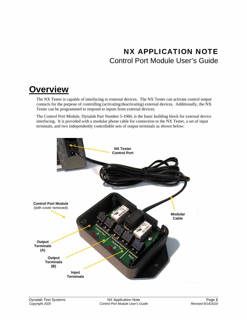
The Control Port Module, Dynalab Part Number 5-1060, is the basic building block for external device interfacing. It is provided with a modular phone cable for connection to the NX Tester, a set of input terminals, and two independently controllable sets of output terminals as shown below:
Control Port Module (with cover removed)
Output Terminals
(A)
Output Terminals
(B) Input
Terminals
Modular Cable
NX Tester Control Port
Dynalab Test Systems NX Application Note Page 2 Copyright 2020 Control Port Module User’s Guide Revised 9/14/2020
Controlling One External Device The most common need for device control is to activate a single device such as a fixture clamp or marking device. The activation of the device is typically done at the conclusion of a successful test. The Control Port Module, part number 5-1060 is available for this purpose. The Control Port Module connects to the NX Tester’s Control Port using standard telephone modular cable (supplied with the Control Port Module). The NX Tester can be programmed to set the Control Port A ON (output contacts closed) or OFF (output contacts open).
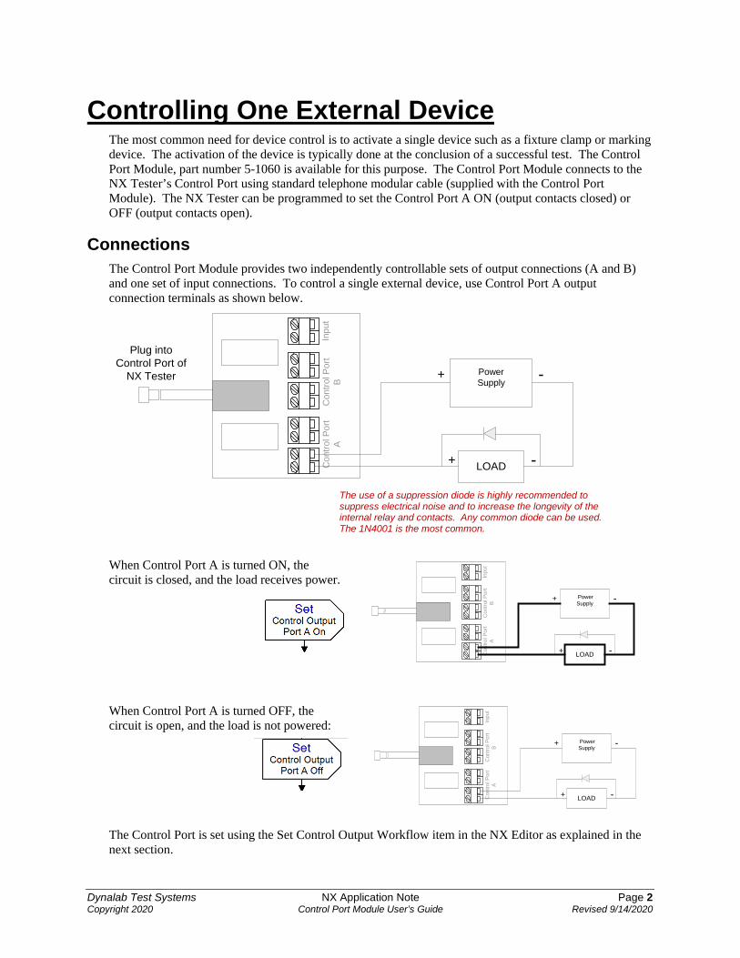
Connections The Control Port Module provides two independently controllable sets of output connections (A and B) and one set of input connections. To control a single external device, use Control Port A output connection terminals as shown below.
Con
trol P
ort
AC
ontro
l Por
tB
Inpu
t
LOAD
PowerSupply
+ -
+ -Plug into
Control Port ofNX Tester
When Control Port A is turned ON, the circuit is closed, and the load receives power.
When Control Port A is turned OFF, the circuit is open, and the load is not powered:
The Control Port is set using the Set Control Output Workflow item in the NX Editor as explained in the next section.
The use of a suppression diode is highly recommended to suppress electrical noise and to increase the longevity of the internal relay and contacts. Any common diode can be used. The 1N4001 is the most common.
Con
trol P
ort
AC
ontro
l Por
tB
Inpu
t
LOAD
PowerSupply
+ -
+ -
Con
trol P
ort
AC
ontro
l Por
tB
Inpu
t
LOAD
PowerSupply
+ -
+ -

Dynalab Test Systems NX Application Note Page 3 Copyright 2020 Control Port Module User’s Guide Revised 9/14/2020
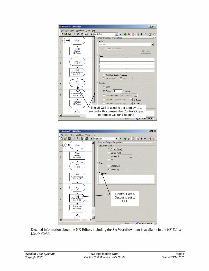
Workflow Using the NX Editor, the NX Tester can be programmed to set the Control Port A ON or OFF. This is accomplished with the use of the Set Control Output Workflow item.
The following Workflow tests a wire harness, sets Control Port A on, delays for 1 second, then sets the Control Port A off. This is a useful Workflow for activating a fixture clamp or marking device after the wire harness passes all tests:
Control Port A Output is set to ON
Dynalab Test Systems NX Application Note Page 4 Copyright 2020 Control Port Module User’s Guide Revised 9/14/2020
Detailed information about the NX Editor, including the Set Workflow item is available in the NX Editor User’s Guide
The UI Cell is used to set a delay of 1 second – this causes the Control Output
to remain ON for 1 second
Control Port A Output is set to
OFF

Dynalab Test Systems NX Application Note Page 5 Copyright 2020 Control Port Module User’s Guide Revised 9/14/2020
Controlling Two External Devices Requirements
NX Tester’s Control Port NX Testers built after November 2006 are capable of controlling two independent control port outputs (A & B) through the NX Tester’s control port. Older NX Testers do not have this capability. NX Testers that can support two independent control port outputs have a label next to the control port that indicates “A_B Control”:
Older NX Testers that cannot control two independent control ports have a label next to the control port that indicates “Control”. The capabilities outlined in this section of the document only apply to NX Testers whose control port is labeled “A_B Control”.
NX Editor Software In order to develop test programs that support two independent control port outputs, NX Editor version 1.0.7.111 or later must be used.
Connections The Control Port Module provides two independently controllable sets of output connections (A and B) and one set of input connections. To independently control two external devices, use Control Port A output terminals for one device and Control Port B output terminals for the other device as shown below.
Con
trol P
ort
AC
ontro
l Por
tB
Inpu
t
LOAD A
PowerSupply
+ -
+ -
LOAD B -+
Note the use of a noise suppression diode for DC applications
This is necessary when the load is an inductive load such as a coil or motor. It is important that it be located as close to the load as possible

Dynalab Test Systems NX Application Note Page 6 Copyright 2020 Control Port Module User’s Guide Revised 9/14/2020
When Control Port A is turned ON, the circuit is closed, and the load receives power.
When Control Port A is turned OFF, the circuit is open, and the load is not powered.
When Control Port B is turned ON, the circuit is closed, and the load receives power.
When Control Port B is turned OFF, the circuit is open, and the load is not powered.
The Control Port is set using the Set Control Output Workflow item in the NX Editor as explained in the next section.
Con
trol P
ort
AC
ontro
l Por
tB
Inpu
t
LOAD A
PowerSupply
+ -
+ -
LOAD B -+
Con
trol P
ort
AC
ontro
l Por
tB
Inpu
t
LOAD A
PowerSupply
+ -
+ -
LOAD B -+
Con
trol P
ort
AC
ontro
l Por
tB
Inpu
t
LOAD A
PowerSupply
+ -
+ -
LOAD B -+
Con
trol P
ort
AC
ontro
l Por
tB
Inpu
t
LOAD A
PowerSupply
+ -
+ -
LOAD B -+

Dynalab Test Systems NX Application Note Page 7 Copyright 2020 Control Port Module User’s Guide Revised 9/14/2020
Workflow Using the NX Editor, the NX Tester can be programmed to independently operate Control Port A and Control Port B. This is accomplished with the use of the Set Control Output Workflow item.
The following example Workflow illustrates independent control of two devices. Device A is powered on before the test begins for the duration of the test, then powered off. Device B is powered on after the test is complete for a duration of one second, then powered off.
Control Port A Output set to ON
Control Port B Output set to ON
Control Port A Output set to OFF
Control Port B Output set to OFF
Time Delay of 1 second
Dynalab Test Systems NX Application Note Page 8 Copyright 2020 Control Port Module User’s Guide Revised 9/14/2020
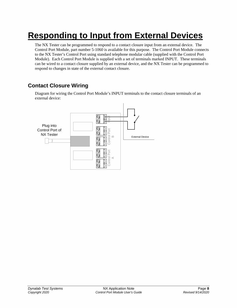
Responding to Input from External Devices The NX Tester can be programmed to respond to a contact closure input from an external device. The Control Port Module, part number 5-1060 is available for this purpose. The Control Port Module connects to the NX Tester’s Control Port using standard telephone modular cable (supplied with the Control Port Module). Each Control Port Module is supplied with a set of terminals marked INPUT. These terminals can be wired to a contact closure supplied by an external device, and the NX Tester can be programmed to respond to changes in state of the external contact closure.
Contact Closure Wiring Diagram for wiring the Control Port Module’s INPUT terminals to the contact closure terminals of an external device:
Con
trol P
ort
AC
ontro
l Por
tB
Inpu
t
Plug intoControl Port of
NX TesterExternal Device
Dynalab Test Systems NX Application Note Page 9 Copyright 2020 Control Port Module User’s Guide Revised 9/14/2020
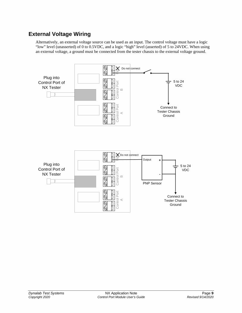
External Voltage Wiring Alternatively, an external voltage source can be used as an input. The control voltage must have a logic “low” level (unasserted) of 0 to 0.5VDC, and a logic “high” level (asserted) of 5 to 24VDC. When using an external voltage, a ground must be connected from the tester chassis to the external voltage ground.
Con
trol P
ort
AC
ontro
l Por
tB
Inpu
t
Plug intoControl Port of
NX Tester5 to 24VDC
Connect toTester Chassis
Ground
Do not connect
Con
trol P
ort
AC
ontro
l Por
tB
Inpu
t
Plug intoControl Port of
NX Tester
5 to 24VDC
Connect toTester Chassis
Ground
+
-
Output
PNP Sensor
Do not connect
Dynalab Test Systems NX Application Note Page 10 Copyright 2020 Control Port Module User’s Guide Revised 9/14/2020
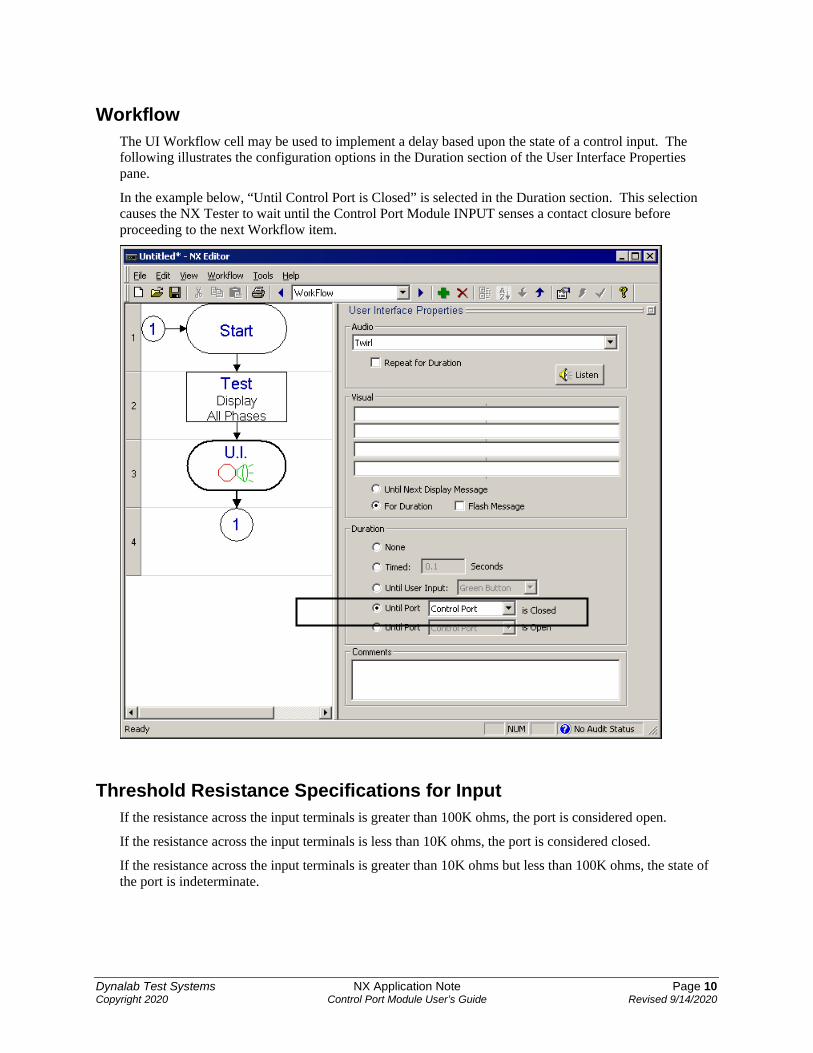
Workflow The UI Workflow cell may be used to implement a delay based upon the state of a control input. The following illustrates the configuration options in the Duration section of the User Interface Properties pane.
In the example below, “Until Control Port is Closed” is selected in the Duration section. This selection causes the NX Tester to wait until the Control Port Module INPUT senses a contact closure before proceeding to the next Workflow item.
Threshold Resistance Specifications for Input If the resistance across the input terminals is greater than 100K ohms, the port is considered open.
If the resistance across the input terminals is less than 10K ohms, the port is considered closed.
If the resistance across the input terminals is greater than 10K ohms but less than 100K ohms, the state of the port is indeterminate.

Dynalab Test Systems NX Application Note Page 11 Copyright 2020 Control Port Module User’s Guide Revised 9/14/2020
In the example below, “Until Control Port is Open” is selected in the Duration section. This selection causes the NX Tester to wait until the Control Port Module INPUT senses an open before proceeding to the next Workflow item.
Contact Ratings The Control Port Module’s relay contacts have the following ratings:
VOLTAGE MAX CURRENT
12 VDC 3 amps
24 VDC 2.5 amps
120 VAC 0.5 amps
240 VAC 0.25 amps
Note: Dynalab does not recommend using voltages over 24VDC. If higher voltages are used, great care should be taken to ensure that the control voltage does not inadvertently come into contact with a test point to avoid damage to the NX Tester’s test point boards.

Dynalab Test Systems NX Application Note Page 12 Copyright 2020 Control Port Module User’s Guide Revised 9/14/2020
Enclosure Dimensions

Dynalab Test Systems NX Application Note Page 13 Copyright 2020 Control Port Module User’s Guide Revised 9/14/2020
First Generation Control Port Module The Control Port Module depicted in this Application Note is a second-generation design. The first generation design did not support two independent outputs – it just supported one output. The following is a picture of the first generation Control Port Module:
The first generation Control Port Module works with all versions of the NX Tester, however it only supports Control Port Output A – it does not support Control Port Output B.
Interfacing to Multiple Devices If there is a need to control more than two external devices, or to respond to input from more than one external device or system, the Modular Control System must be used. Detailed information about the Modular Control System is available in the Application Note entitled Modular Control System.
NX Tester
Cable
Control Port Module
Input Terminal
Output Terminal
© Copyright, 2020, Dynalab Test Systems, Inc. All rights reserved. All features/functions mentioned within are subject to change. This document is for
informational purposes only. Dynalab Test Systems, Inc., makes no warranties, expressed or implied, in this document. Dynalab® and NX® are trademarks of Dynalab Test Systems, Inc.